1
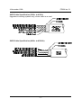
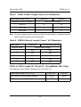
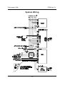
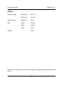
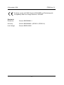
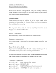
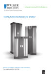
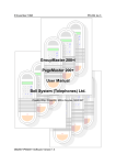
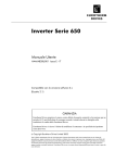
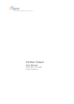
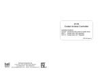
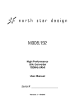
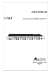
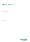
4 November 1998
PD006 Iss 3.1
AllCall 200+ Installation/Operators
Manual
Bell System (Telephones) Ltd.
Presley Way, Crownhill, Milton Keynes, MK8 0ET
A200+ Software Version 1.1
4 November 1998
PD006 Iss 3.1
Contents
System Description . . . . . . . . . . . . . . . . . . . . . . . . . . . . . . . . . . . . . . . . . . . . . . . . . .
AllCall Amplifier (A200+) . . . . . . . . . . . . . . . . . . . . . . . . . . . . . . . . . . . . . . . .
KS200+ Unit . . . . . . . . . . . . . . . . . . . . . . . . . . . . . . . . . . . . . . . . . . . . . . . . . .
Emergency Button . . . . . . . . . . . . . . . . . . . . . . . . . . . . . . . . . . . . . . . . . . . . .
Multi-controller Systems (GroupMaster 200+ Software) . . . . . . . . . . . . . . . .
Operating The KS200+ . . . . . . . . . . . . . . . . . . . . . . . . . . . . . . . . . . . . . . . . .
Operation with GroupMaster 200+ Software . . . . . . . . . . . . . . . . . . . . . . . . .
3
3
3
3
3
4
4
Cable Requirements . . . . . . . . . . . . . . . . . . . . . . . . . . . . . . . . . . . . . . . . . . . . . . . . . 5
Cable Planning . . . . . . . . . . . . . . . . . . . . . . . . . . . . . . . . . . . . . . . . . . . . . . . . . . . . .
Table 1. A200+ Feeder Length (Cores 4 & 5 Diameters) . . . . . . . . . . . . . . .
Table 2. KS200+ Branch Length (Cores 1 & 2 Diameters) . . . . . . . . . . . . . .
C200+ to C200+ length (S1, S2 and TL - GroupMaster 200+ Only) . . . . . . .
7
8
8
8
Power Supply Rating . . . . . . . . . . . . . . . . . . . . . . . . . . . . . . . . . . . . . . . . . . . . . . . . 9
Installation . . . . . . . . . . . . . . . . . . . . . . . . . . . . . . . . . . . . . . . . . . . . . . . . . . . . . . . 10
Cable Entries . . . . . . . . . . . . . . . . . . . . . . . . . . . . . . . . . . . . . . . . . . . . . . . . 10
Important Safety Information (PSU138A-6) . . . . . . . . . . . . . . . . . . . . . . . . . . . . . . 11
Mains Cables (PSU138A-6) . . . . . . . . . . . . . . . . . . . . . . . . . . . . . . . . . . . . . 11
Battery . . . . . . . . . . . . . . . . . . . . . . . . . . . . . . . . . . . . . . . . . . . . . . . . . . . . . 12
System Wiring . . . . . . . . . . . . . . . . . . . . . . . . . . . . . . . . . . . . . . . . . . . . . . . . . . . . 13
Commissioning . . . . . . . . . . . . . . . . . . . . . . . . . . . . . . . . . . . . . . . . . . . . . . . . . . . .
Emergency Tone (C200+ Setup) . . . . . . . . . . . . . . . . . . . . . . . . . . . . . . . . .
AllCall Enabled (M200+ Setup) . . . . . . . . . . . . . . . . . . . . . . . . . . . . . . . . . .
Volume Adjustment (A200+ Setup) . . . . . . . . . . . . . . . . . . . . . . . . . . . . . . .
14
14
14
14
Specifications . . . . . . . . . . . . . . . . . . . . . . . . . . . . . . . . . . . . . . . . . . . . . . . . . . . . . 15
A200+ . . . . . . . . . . . . . . . . . . . . . . . . . . . . . . . . . . . . . . . . . . . . . . . . . . . . . 15
KS200+ . . . . . . . . . . . . . . . . . . . . . . . . . . . . . . . . . . . . . . . . . . . . . . . . . . . . 16
4 November 1998
PD006 Iss 3.1
System Description
AllCall Amplifier (A200+)
The AllCall amplifier (A200+) is used to generate an emergency evacuation tone or a
general announcement on all room units within an M200+ system.
An additional benefit of the A200+, is that it removes the limit to the number of Monitor
stations that can sound alarm tones simultaneously.
The AllCall amplifier is supplied in an IP55 lockable steel cabinet with its own internal
power supply (PSU138A-10) and requires a 12V 6AH lead-acid battery. It is intended
for occasional use, requiring a battery charge time in between operations.
System Requirements:
C200+ (PCB issue 2.1 or later) fitted with software version 2.1 or later.
M200+’s version 1.0 or later
KS200+ Unit
One or more KS200+ units can be connected to the A200+. The unit has two key
switches and a microphone; one keyswitch will operate the emergency alarm, the
other is used to make a general announcement with the microphone.
Emergency Button
Emergency button(s) can be used in place of KS200+ units; they will operate the
emergency tone only.
Multi-controller Systems (GroupMaster 200+ Software)
Normally each C200+ on the system requires an AllCall amplifier; However, if a C200+
has 20 or less M200+ room units, the AllCall Amplifier may be omitted provided that:1.
There is at least one AllCall on the system
2.
The total number of M200+ room units connected to a C200+’s without an
AllCall amplifier is 50 or less.
-3-
4 November 1998
PD006 Iss 3.1
Operating The KS200+
Operating this key switch will put the system into
emergency alarm mode. All M200+ room units on the
system will sound an alarm tone.
Operating this key switch will put the system into general
announcement mode; by pressing the talk button (on the
right of the symbol) and speaking into the grill on the front
of the KS200+ unit, the operator can make an
announcement to all M200+ room units on the system.
Operation with GroupMaster 200+ Software
See the GroupMaster 200+ User Manual.
-4-
4 November 1998
PD006 Iss 3.1
Cable Requirements
The AllCall amplifier is connected to the rest of the M200+ system using a 5 core cable
which carries power, speech and data. The KS200+ is connected to the AllCall
amplifier using a 6 core cable.
A single cable of type JE-Y(SY)Y, BSTL ‘S6CR' (illustrated below) or equivalent, must
be used to ensure correct operation of the system and compliance with European EMC
directive (89/336/EEC).
JE-Y(ST)Y Cable Specification (C200+ to A200+)
For all new systems.
JE-Y(ST)Y Cable Specification (A200+ to KS200+)
-5-
4 November 1998
PD006 Iss 3.1
S6CR Cable Specification (C200+ to A200+)
Upgrades to existing systems only, where cable is re-used
S6CR Cable Specification (A200+ to KS200+)
-6-
4 November 1998
PD006 Iss 3.1
Cable Planning
-7-
4 November 1998
PD006 Iss 3.1
Table 1. A200+ Feeder Length (Cores 4 & 5 Diameters)
Cable Used (Cores 4 & 5)
0.5mm Dia.
Total M200+ Units on System.
1mm Dia.
A200+ Feeder Length
Up to 50
8
35
Up to 100
4
15
Up to 250
5
Note The above table gives the maximum A200+ feeder length, it is advised that this
cable length be kept as short as possible.
Table 2. KS200+ Branch Length (Cores 1 & 2 Diameters)
Cable Used
0.5mm Dia.
KS200+ Units
2 X 0.5mm Dia./1mm Dia.
Branch Cable Length
1
200
400
2
200
400
3
200
400
4
175
350
5
150
300
C200+ to C200+ length (S1, S2 and TL - GroupMaster 200+ Only)
The maximum cable distance between any two C200+’s is:Cable Used (Cores S1, S2 & TL)
If all C200+’s have an AllCall amplifier
If C200+’s without AllCall amplifiers are in use
-8-
0.5mm Dia.
1mm Dia.
100m
100m
8m
35m
4 November 1998
PD006 Iss 3.1
Power Supply Rating
To calculate the power requirement for the A200+ and the M200 system as a whole see
M200+ Installation Manual.
-9-
4 November 1998
PD006 Iss 3.1
Installation
The cabinet must be installed in a protected indoor environment, close to a 240V
electrical supply, e.g. an electrical cupboard.
KS200+ units should be located close to where they will be used such as an office or
staff room. Care must be taken not to place the KS200+ unit too close to any of the
M200+ room units as feedback may result. If this unavoidable, the Allcall feature on the
Room Unit in question must be disabled.
Cable Entries
Before any cabling can be carried out the cable entry plate must be drilled and suitable
cable glands fitted. To avoid metal fragments entering the cabinet always remove the
panel before drilling.
- 10 -
4 November 1998
PD006 Iss 3.1
Important Safety Information (PSU138A-6)
Connections to the 240V AC mains supply must be carried out by a qualified electrician
or similar competent person, and made in accordance with accepted safety practices.
A good mains safety earth must be connected to cabinet and Power Supply (PSU138A6). A two-pole switch (as provided by a Consumer Unit or Switch-Fuse) must be
included to isolate both Live and Neutral during Installation or Maintenance. The circuit
must be protected by a current limiting fuse or other device with a maximum rating of
5A.
The transformer is protected by a fuse; always replace this with the correct type and
rating:
T315mA 250V
(20mm glass fuse, 315mA, 250V, Time delay,
approved to BS EN 60127 or equivalent.)
Mains Cables (PSU138A-6)
Use only mains cable to BS6004, BS6500, or equivalent, within the following specified
limits:
Minimum
Maximum
Conductor Diameter
1.0mm (0.75mm2)
2.25mm (4mm2)
Cable Diameter
4.0mm
8.0mm
When fitting the cables to the PSU138A-6 (both primary and secondary) only feed them
through the blind grommets provided, first cutting a slit in each. Do not remove the
grommets or make any other holes.
- 11 -
4 November 1998
PD006 Iss 3.1
Battery
The PSU requires a sealed lead-acid battery rated at 12V 6AH (YUASA NP6-12). The
battery is an essential part of the AllCall amplifier and must be fitted on all systems.
To avoid build up of explosive gases do not block any vents on the cabinet which
maybe apparent.
Care must be taken to ensure the battery terminals are not shorted together by metal
objects as this may constitute a Fire Hazard.
Observe the correct polarity when connecting:
Red wire
-
Positive (+)
Black wire
-
Negative (-)
The Battery is protected by a fuse, always replace this with the correct type and rating:
F6.3A 250V (20mm glass fuse, 6.3A, Fast Blow, approved to BS EN
60127 or equivalent.)
Note The battery is normally shipped separately.
- 12 -
4 November 1998
PD006 Iss 3.1
System Wiring
- 13 -
4 November 1998
Commissioning
Emergency Tone (C200+ Setup)
can be set to a variety of different tones and duty rates (On/Off times) to
the emergency tone from other alarm tones. The tone is setup using the
setup software(V1.4 or later), see the M200+ Installation manual for details of
AllCall Enabled (M200+ Setup)
is a M200+ Room unit parameter that controls the speaker in a room unit when the
system is active, normally this should be set to ON and only changed to
on
located close to the KS200+ unit to eliminate unwanted audio feedback. For
Volume Adjustment (A200+ Setup)
emergency tone volume adjustment is on the C200+ (VR1) and this should be set
There
SPEECH VOL) these should normally be set to maximum.
- 14 -
4 November 1998
PD006 Iss 3.1
Specifications
A200+
GPI200+
Supply Voltage
(Maximum)
28V D.C.
(Minimum)
18V D.C.
Supply Current
(Maximum)
175mA
Size
Height
500mm
Width
400mm
Depth
155mm
Weight
19Kg
Amplifier
Supply Voltage
12v D.C.
Output
75W Can drive 250 M200+
PSU138A-6
Supply Voltage
230Va ± 10%
Output Voltage
13.5V D.C.
Charging Current
(Maximum)
1Amp
- 15 -
4 November 1998
PD006 Iss 3.1
KS200+
Supply Voltage
(Maximum)
28V D.C.
(Minimum)
18V D.C.
Supply Current
(Maximum)
50mA
Size
Height
220mm
Width
160mm
Depth
65mm
Weight
700g
Bell System (Telephones) Ltd reserves the right to change these specifications without
notice.
- 16 -
4 November 1998
C
PD006 Iss 3.1
Products comply with EMC directive 89/336/EEC on Electromagnetic
Compatibility and Low Voltage Directive 72/23/EEC
Standards
Emissions:
Generic BSEN50081-1
Immunity:
Generic BSEN50082-1 (IEC801-2, IEC801-6)
Low Voltage:
Generic BSEN 60950
- 17 -