1
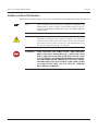
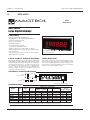
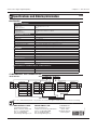
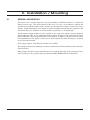
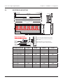
GAD Series Large Digital Displays User’s manual While every precaution has been exercised in the compilation of this document to ensure the accuracy of its contents, Magtrol assumes no responsibility for errors or omissions. Additionally, no liability is assumed for any damages that may result from the use of the information contained within this publication. COPYRIGHT Copyright ©2012 Magtrol, Inc. All rights reserved. Copying or reproduction of all or any part of the contents of this manual without the express permission of Magtrol is strictly prohibited. First Edition – July 2012 Revisions To This Manual The contents of this manual are subject to change without prior notice. Should revisions be necessary, updates to all Magtrol User’s Manuals can be found at Magtrol’s web site at www.magtrol.com/support/manuals.htm. Please compare the date of this manual with the revision date on the web site, then refer to the manual’s Table of Revisions for any changes/updates that have been made since this edition.. TABLE OF REVISIONS DATE EDITION CHANGES i SECTION Table of Contents REVISIONS TO THIS MANUAL.................................................................................................................I TABLE OF REVISIONS.......................................................................................................................................................I TABLE OF CONTENTS............................................................................................................................II PREFACE................................................................................................................................................ IV PURPOSE OF THIS MANUAL......................................................................................................................................... IV WHO SHOULD USE THIS MANUAL............................................................................................................................. IV MANUAL ORGANIZATION............................................................................................................................................ IV SYMBOLS USED IN THIS MANUAL.............................................................................................................................. V 1. INTRODUCTION..................................................................................................................................1 1.1 GENERAL INFORMATION...................................................................................................................................... 1 1.2 DATA SHEET............................................................................................................................................................. 2 2. INSTALLATION / MOUNTING.............................................................................................................4 2.1 GENERAL DESCRIPTION....................................................................................................................................... 4 2.2 SUSPENSION MOUNTING...................................................................................................................................... 5 2.3 CONNECTIONS......................................................................................................................................................... 6 2.3.1 Input board / power supply board........................................................................................................................ 6 2.3.2 Output board........................................................................................................................................................ 7 2.4 INSTALLATION HINTS FOR BEST PERFORMANCE.......................................................................................... 8 3. MENU MODES...................................................................................................................................10 3.1 3.2 3.3 3.4 3.5 3.6 3.7 3.8 3.9 3.10 3.11 3.12 3.13 3.14 3.15 3.16 3.17 3.18 3.19 3.20 3.21 3.22 3.23 3.24 EASY OR ADVANCED MENU MODE.................................................................................................................. 10 LANGUAGE SELECTION...................................................................................................................................... 11 DISPLAY BRIGHTNESS......................................................................................................................................... 12 METER CALIBRATION MODE............................................................................................................................. 13 DIRECT CALIBRATION - FULL SCALE SETTING............................................................................................ 14 DIRECT CALIBRATION - ZERO SETTING.......................................................................................................... 15 LINEARISATION WITH DIRECT CALIBRATION.............................................................................................. 16 THEORETICAL CALIBRATION. - DECIMAL POINT & FULL SCALE............................................................ 18 THEORETICAL CALIBRATION. - LOW END CALIBRATION.......................................................................... 19 LINEARISATION WITH THEORETICAL CAL.................................................................................................... 20 SENSOR DRIFT CORRECTION............................................................................................................................ 22 LOGIC INPUT FUNCTIONS.................................................................................................................................. 23 LOGIC INPUT CONNECTIONS AND FRONT BUTTONS.................................................................................. 24 FACTORY DEFAULTS............................................................................................................................................ 25 CALIBRATION AUDIT NUMBER......................................................................................................................... 25 SIGNAL FILTERING / AVERAGING..................................................................................................................... 26 FILTER JUMP VALUE............................................................................................................................................. 27 LAST DIGIT ROUNDING UP BY 1, 2, 5, 10, 20 OR 50........................................................................................ 28 SCALE FACTOR ADJUSTMENT........................................................................................................................... 29 OFFSET ADJUSTMENT......................................................................................................................................... 30 MENU TIMEOUT ADJUSTMENT......................................................................................................................... 31 REVERSE DISPLAY FUNCTION (MIRROR IMAGE)......................................................................................... 32 BOOTUP ROUTINE CHOICES............................................................................................................................... 33 ERROR CODES AND FAULT FINDING................................................................................................................ 34 ii GAD Series Large Digital Displays Table of contents 4. OPTION BOARDS.............................................................................................................................35 4.1 HOW TO INSTALL OPTION BOARDS................................................................................................................. 35 APPENDIX A :........................................................................................................................................36 WASTE ELECTRICAL ELECTRONIC EQUIPMENT (WEEE)............................................................................ 36 iii Preface PURPOSE OF THIS MANUAL This manual has all the necessary information regarding the installation, connection and use of Magtrol's large digital display GAD Serie. To achieve maximum capability and ensure proper use of the system, please read this manual in its entirety before operating. Keep the manual in a safe place for quick reference whenever a question should arise. WHO SHOULD USE THIS MANUAL This manual is for users who want to install and use large digital display GAD Serie for use with different sensor types. The user should have suitable technical training in mechanics and electronics so as to allow him to install and use this display without risk. MANUAL ORGANIZATION This section gives an overview of the structure of the manual and the information contained within it. Some information has been deliberately repeated in different sections of the document to minimize cross-referencing and to facilitate understanding through reiteration. Summary of the different chapters : Chapter 1: INTRODUCTION – Contains the technical data sheet of the large digital display GAD Serie and gives its technical characteristics as well as a brief overview of the application fields. Chapter 2: INSTALLATION / MOUNTING – Contains the mounting and configuration explanations for the GAD Serie. Chapter 3: MENU MODES – Provides instructions for setup and configuration modes available on the GAD. Chapter 4: OPTION BOARDS – Contains operating mode to install option boards. iv Preface GAD Series Large Digital Displays SYMBOLS USED IN THIS MANUAL The following symbols and type styles may be used in this manual to highlight certain parts of the text: Note: Caution: This is intended to draw the operator’s attention to complementary information or advice relating to the subject being treated. It introduces information enabling the correct and optimal function of the product. This is used to draw the operator’s attention to information, directives, procedures, etc. which, if ignored, may result in damage to the material being used. The associated text describes the necessary precautions to take and the consequences that may arise if these precautions are ignored. WARNING! THIS INTRODUCES DIRECTIVES, PROCEDURES, PRECAUTIONARY MEASURES, ETC. WHICH MUST BE EXECUTED OR FOLLOWED WITH THE UTMOST CARE AND ATTENTION, OTHERWISE THE PERSONAL SAFETY OF THE OPERATOR OR THIRD PARTY MAY BE AT RISK. THE READER MUST ABSOLUTELY TAKE NOTE OF THE ACCOMPANYING TEXT, AND ACT UPON IT , BEFORE PROCEEDING FURTHER. v 1. Introduction 1.1 GENERAL INFORMATION Magtrol Large Digital Displays are used with Load Monitoring Units (LMUs) or signal conditioners (AN Series), as part of a complete measurement system. Magtrol load measuring pins, which measure load and force to provide overload protection, are available for a wide range of Load-Force-Weight, and in various executions and accuracy classes. Combined, these products constitute an ideal safe measurement system for continuous overload monitoring. 1 Chapter 1 – Introduction 1.2 GAD Series Large Digital Displays DATA SHEET M AGTROL GAD Data Sheet GAD Series Large Digital Displays Features • Suspension-mounted large LED display • Digit Heights: 57, 102, 150, 200, 300, and 400 mm • Protection class IP 65 (sealed) • Fully corrosion resistant • Adjustable brightness • Power supply: 100 to 240 VAC (optional 11 to 30 VDC or 48 VAC) • Input: 0 to 10 V, 0 to 5 V or 0 to 20mA, 4 to 20 mA • Fully scalable in kg, tonne (t), kN, and other engineering units • Auto-tare function • Optional voltage (0 to 10 V) or current (4 to 20 mA) output • Optional RS-232 serial output Model GAD 6/102/1/0/1/0/0 Large Digital Display Load-Force-Weight systems description Magtrol Large Digital Displays are used with Load Monitoring Units (LMUs) or signal conditioners (AN Series), as part of a complete measurement system. Magtrol load measuring pins, which measure load and force to provide overload protection, are available for a wide range of Load-Force-Weight, and in various executions and accuracy classes. Combined, these products constitute an ideal safe measurement system for continuous overload monitoring. These high quality, large character digital displays can be used for crane weight display, process weight display, and all other remote weighing applications. They use microprocessor based technology for high reliability and have a non-volatile memory to store all the calibration data. system conFiguration LMU 21x Load Monitoring Unit KG LB 2xx Load Measuring Pin GAD 057 – GAD 400 LARGE DIGITAL DISPLAY OpTiOn: unit display extension dimensions MODEL Digits Digit Height Viewing Distance Dimensions of the Display Width Depth Height* 4 digits 6 digits mm m mm mm mm mm 4 or 6 57 20 279.5 376 154.5 77 GAD 057 ** GAD 102 4 or 6 102 40 434 616 195.5 77 GAD 150 4 or 6 150 60 580 820 246 77 GAD 200 4 or 6 200 80 750 1072 290 77 GAD 300 4 or 6 300 120 1050 1540 408 77 GAD 400 4 or 6 400 160 1368 2020 515 77 * The display height does not include the stuffing glands, which are approximately 25 mm (1 inch) high. ** For the model GAD 057 with 4 digits, adding an optional module requires the unit display extension option. Weight 4 digits 6 digits kg 1.3 3.1 3.9 4.7 10.6 13.0 kg 1.7 3.9 4.3 6.4 14.9 16.0 www.magtrol.com 1 2 Chapter 1 – Introduction GAD Series Large Digital Displays Specifications and Ordering Information GAD ratings SIGNAL PROCESSING Voltage input: • Input range 0 to 10 V, 0 to 5 V, 1 to 5 V • Input impedance 1 MΩ Current input: • Input Range 0 to 10 mA, 0 to 20 mA, 4 to 20 mA • Input Impedance 33 Ω MEASUREMENT DISPLAY Type 7 segments Display definition -1999 to 9999 (4 digits) or -199999 to 999999 (6 digits) Digits/Color 4 or 6 digits/red Scaling Digital zero and full scale adjustable by programming keys Decimal point Position adjustable by programming keys Filtering/Signal smoothing Time constant adjustable between 0 and 25 seconds Count-by function Round-off of the last digits with steps of 1, 2, 5, or 10 ACCURACY Resolution 1/400 000 Maximum error ±0,05% of full scale Stability ±25 ppm/°C (full scale) and ±30 ppm/°C (offset) Reading rate 10 readings per second Response time 0.1 seconds POWER SUPPLY AC 100 to 240 VAC 45/60 Hz, (option) 48 VAC DC (option) 11 to 30 VDC Power consumption 40 VA max. ENVIRONMENTAL AND MECHANICAL CHARACTERISTICS Operating temperature 0°C to +50°C (down to -25°C as an option) Storage temperature -20°C à +70°C Protection Class IP 65 ordering inFormation Model Number: Digits GAD X / XXX / X / X / X / X Digit height Units Power supply Option Calibration 4 4 09 57 mm 057 1 none 0 0 100 to 240 VAC 1 1 none 0 0 none 0 6 6 10 102 mm 102 2 kg kg 1 11 to 30 VDC 2 2 current output I 1 with calibration C 48 VAC 3 3 150 mm 150 3 t t 2 200 mm 200 4 kN kN 3 other x 4 300 mm 300 5 400 mm 400 6 P/N 957.09. XX X X voltage output U 2 output RS-232 RS 3 X X C X Due to the continual development of our products, we reserve the right to modify specifications without forewarning. magtroL inc 70 Gardenville Parkway Buffalo, New York 14224 USA Phone: +1 716 668 5555 Fax: +1 716 668 8705 E-mail: [email protected] magtroL sa Route de Montena 77 1728 Rossens / Fribourg, Switzerland Phone: +41 (0)26 407 3000 Fax: +41 (0)26 407 3001 E-mail: [email protected] 3 Subsidiaries in: Germany • France China • India Worldwide Network of Sales Agents GAD-US 01/12 www.magtrol.com 2. Installation / Mounting 2.1 GENERAL DESCRIPTION To be made, such a weight, temperature, pressure, humidity etc. Different models are available for different sensor types. The main function of this series is to give a clear numeric readout of the variable being monitored. Most models include an excitation power output, to power the sensor directly. Various digit heights are available, to suit the maximum viewing distance required in each installation. For every 10 metres of viewing distance required, use 1” of digit height. Various optional output modules are also available to give alarm relay outputs, analogue output or digital communications, or any combination of these options. Displays are programmed using front panel pushbuttons. The front panel buttons can be disabled. In addition, you can connect 4 remote wired pushbuttons to the display, so that you can make adjustments while the display is mounted in an inaccessible location. Power supply options : 100-240 VAC, 48VAC or 11-30VDC These displays must be installed fully assembled, and must be installed according to local electrical installation rules. When properly installed, and provided they have been ordered with cable glands exiting the lower surface of the case, they provide ingress protection to IP65 / NEMA4X from all directions. 4 Chapter 2 – Installation / Configuration GAD Series Large Digital Displays SUSPENSION MOUNTING 6.35mmO 6.35mmO Plan View 15mmO 25mm 220mm 207.5mm 157.5mm 15mmO X mm Y mm Short-drop mounting holes Long-drop mounting holes W mm 77 mm 8.8.8.8.8.8. dg H mm OK 25mm Cable Glands. Number of glands depends on installed options. Detail showing bracket Case 2.2 M8 bolt Spring washer Flat washer Bracket Rubber washer Display boss Display format mm You can order these displays with the cable glands in the bottom surface (as shown) the rear, or top. Rear glands allow you to mount the display on top of a cubicle, using the brackets X mm H mm W mm Y mm 57 - 4 digits digital 233.5 154.5 279.5 263.5 57 - 6 digits digital 330 154.5 376 360 102 - 4 digits digital 388 195.5 434 418 102 - 6 digits digital 570 195.5 616 600 150 - 4 digits 534 246 580 564 150 - 6 digits 774 246 820 804 200 - 4 digits 704 290 750 734 200 - 6 digits 1026 290 1072 1056 300 - 4 digits 1004 408 1050 1034 300 - 6 digits 1494 408 1540 1524 400 - 4 digits 1322 515 1368 1352 400 - 6 digits 1974 515 2020 2004 5 Chapter 2 – Installation / Configuration GAD Series Large Digital Displays 2.3 CONNECTIONS 2.3.1 Input board / power supply board There is a wide range of possible locations for the input board, output board and power supply board/s. Their locations depend on the height of digits, number of digits, brightness of digits and any installed options. Because the permutation of possible locations is large, we will not describe the location of boards within the display, but simply identify the connectors and their functions on each board, below ... WARNING ! DISCONNECT ALL POWER BEFORE REMOVING THE REAR OF THE DISPLAY OK and signal input board Processor Digit Processor and signal input board 9 CC.3 8 CC.2 10 11 12 13 N L - + Remote contacts (5V DC 1mA) Connection Examples Internal power link, installed by the factory CC.1 7 Common 6 Alarm Lock Calib’n Lock 5 Excitation + V+ 4 no connection 3 mA + 2 Signal - Excitation - 1 Power Earth Logic Inputs Signal Input & Excitation A) 4-20mA direct, Term2 = -, Term3=+ B) 4-20mA 2 wire transmitter, link terminals 1&2, Term3 = -, Term6=+ C) 0-10V direct, Term2 = -, Term4 = + D) 3 wire potentiomer (if POT option ordered) link terminals 1&2 to low end of potentiometer, Term4 to wiper, Term6 to high end of pot Power Supply board Fuse Earth - or N + or L Customer-supplied disconnection and overload protection devices N L - + Fuse Circuit breaker Switch Power Earth E Inside the enclosure Outside the enclosure 6 Chapter 2 – Installation / Configuration GAD Series Large Digital Displays Output board caution Connectors may be present even if output options are not installed. Refer to rating label to see installed options. WARNING ! DISCONNECT ALL POWER BEFORE REMOVING THE REAR OF THE DISPLAY Analog Serial Data output output option option Analog Serial Data output output 19 option 18 17 16option 15 14 + TxD R S 2 3 2 15 14 - 16 + TxD Enable to activate or de-activate the RS232 serial output. Connect to Comm to continually transmit data. 17 RxD 18 Comm RxD EnableComm Enable is used in mode C1 to activate or de-activate the 19 RS232 serial output. Connect to Comm to continually Enabletransmit is useddata. in mode C1 - R S 2 3 2 Remote programming button connector On one of the display boards, you will find a 7 way connector, to which you can wire remote programming buttons, to allow adjustment of the display’s settings when the display is inaccessible. Output Set2 OK Set1 Output Common Set2 Common Set1 Enable Common enable front panel buttons Display’s front panel Rear case screws - please note Common buttons enabled/disa- Enable onlybled need to be gently tightened. Do not use tools to tighten or loosen the screws, as this could cause damage to the internal threads. Rear case screws - please note only need to be gently tightened. Do not use tools to tighten or loosen the screws, as this could cause damage to the internal threads. 7 Remote buttons OK Remote buttons enable front panel buttons Display’s front panel buttons enabled/disabled Button function You can also enable or disable the display’s front panel buttons, either by a remote contact closure, or by an on-board push-on jumper switch, which is located near to the remote button connector. When the contact is closed, or the push-on switch fitted, the front buttons are enabled. Button function 2.3.2 Chapter 2 – Installation / Configuration INSTALLATION HINTS FOR BEST PERFORMANCE This section offers several suggestions which will help you get the best performance from your measurement system. Some sensors generate comparitively small signals which can easily be corrupted by the potentially high level of electrical noise which can be created by electrical machinery such as motors, welding systems, discharge lighting, AC power inverters and solenoids. These steps will ensure you get the best possible performance from your system. 1. Use good quality screened signal cable K-414. 2. If you are using multi-pair twisted cable, each pair should be dedicated to a single display as shown opposite, for maximum noise immunity.This will ensure that any electrical noise induced in the cable is properly cancelled. Mixing destinations carelessly amongst the twisted pairs can actually worsen noise performance. 3. The cable should be routed away from noisy wiring and devices such as power feeds from inverters, discharge-lighting cables, welder cabling etc, and should preferrably be routed in a dedicated low voltage signalling/instrumentation conduit or cable tray. 4. Screened cable should be earthed at the display end only. 5. All wires and screens coming out of the screened cable should be kept as short as possible to minimise pickup of noise. Power Input Safe Area Logic Input Hazardous Area Signal Input 6. If you are using barriers, you should earth your screen as shown below, paying particular care that you do not earth both ends of any run of of cable. Barriers Sensor EARTH 2.4 GAD Series Large Digital Displays Length of screened cable Do not connect screen at this end. Sensor connections Connect screen to earth ONLY at this end. Length of screened cable Do not connect screen at this end. Barrier connections 8 Connect screen to earth ONLY at this end. Terminal 7 on logic input connector Clean Earth Display connections Chapter 2 – Installation / Configuration GAD Series Large Digital Displays When using multi-core screened cable to connect several displays to several sensors, please be sure to use one twisted pair for each display and sensor. Note: Do NOT use a wire from one pair for signal positive and a wire from another pair for signal negative, as this will prevent the twisted cables form cancelling any induced electrical noise. Sensor 1 Display 1 Sensor 2 Display 2 Sensor 3 Display 3 Sensors Displays 9 3. Menu modes 3.1 EASY OR ADVANCED MENU MODE You can choose from two menu modes. 1. Easy Mode - This limits the menu to the most commonly required features, in order to make it less complex and easier to navigate. This is the default level. 2. Advanced Mode - This gives you access to all available menu features. Each menu feature in this manual has a heading note to tell you whether it is available in Easy or Advanced mode. How to choose menu mode: 1 This feature is available in Easy and Advanced Modes Set1 Set2 Output Alarms Digit Max/Min Reset OK Lockout Switch must be OFF Circuit board 2 Set1 Set2 Output Alarms Digit Max/Min Reset OK 3 Set1 Set2 Output Alarms Digit Max/Min Reset OK 4 Press to toggle Set1 Set2 Output Alarms Digit Max/Min Reset OK Press to accept 10 OFF ON Press OK a few times, until you see Adv. or EASy Each press of the DOWN arrow, or UP arrow will alternate between showing Adv. or EASy Press OK to select your choice. Done! Chapter 3 – Menu modes GAD Series Large Digital Displays 3.2 LANGUAGE SELECTION You can select English or French menu prompts. 1 This feature is available in Easy and Advanced Modes Set1 Set2 Output Alarms Digit Max/Min Reset OK Lockout Switch must be OFF Circuit board 2 Set1 Set2 Output Alarms Digit Max/Min Reset OK Press to toggle Display shows UI Eng (Default) for User Interface English or UI FrA for User Interface French 3 Set1 Set2 Output Alarms Digit Max/Min Reset OK Done! Press to accept 11 OFF ON Chapter 3 – Menu modes 3.3 GAD Series Large Digital Displays DISPLAY BRIGHTNESS This feature is available in Easy and Advanced Modes 1 Set2 Set1 Digit Max/Min Output Alarms Reset OK OFF Lockout Switch must be ON Circuit board Press 3 seconds 2 Set1 Set2 Output Alarms Digit Max/Min Reset OK Press for 3 seconds 3 Set1 Set2 Output Alarms Digit Max/Min Reset OK ON Display shows bright Each press of the UP button will select a new brightness level.There are 7 brightness levels to choose from. (Default = Full brightness) Done! Press to accept ! Did you know, we make this display in two brightness versions? Standard brightness for use inside, and Daylight Viewing for use outits part number. 12 Chapter 3 – Menu modes GAD Series Large Digital Displays 3.4 METER CALIBRATION MODE You can choose from two main calibration methods. 1. Direct Calibration - this is when you connect the meter to your system and make the meter read what you want it to, at 2 different points. This is the preferred calibration method, because it allows you to calibrate the system as a whole. 2. Theoretical Calibration - this is when you type in the sensor’s theoretical signal level at the bottom and top of its range and then type in the value the display should show, for each signal level 1 2 This feature is available in Easy and Advanced Modes Set1 Set2 Output Alarms Digit Max/Min Reset OK Lockout Switch must be OFF Circuit board Press 3 seconds Set1 Set2 Output Alarms Digit Max/Min Reset OK OFF ON Display shows CAL Src then dIreCt or 3 thEor (Default) Press to select dirECt or thEor Set1 Set2 Output Alarms Digit Max/Min Reset OK Press to accept 4 If you chose Theoretical, you will now be asked whether your input signal will be DC Current or DC voltage ... the display will show Input followed by dC A or dC V Set1 Set2 Output Alarms Digit Max/Min Reset OK Press to select dc A or dc V 5 Set1 Set2 Output Alarms Digit Max/Min Reset OK Display shows Input then dC A for current or dC V for voltage (Default) Done! Press to accept 13 Chapter 3 – Menu modes 3.5 GAD Series Large Digital Displays DIRECT CALIBRATION - FULL SCALE SETTING This is when you connect the meter to your system and make the meter read what you want it to, at 2 different points. This is the preferred calibration method, because it allows you to calibrate the system as a whole. How to do direct calibration:If you have not done so before, please select Direct Calibration mode from the previous page. First we recommend you set the FULL SCALE calibration ... 1 This feature is available in Easy and Advanced Modes Set2 Set1 Digit Max/Min Output Alarms Reset OK Press 3 seconds 2 Set1 Set2 Output Alarms Digit Max/Min Reset OK 3 Set1 Set2 Output Alarms Digit Max/Min Reset OK 4 5 Press for 3 seconds Output Alarms Max/Min Reset OK Set1 Set2 Output Alarms Digit Max/Min Reset OK Set1 Digit Set2 Lockout Switch must be OFF Display shows direCt followed by SEt Hi Circuit board OFF ON Apply the highest calibration signal you can achieve, ideally 100% of system capacity.You can use less, but you will get better accuracy with higher signals. Press Set2 for 3 seconds. You can now set your decimal point position using the UP or DOWN buttons. Press OK when done. You can now set the display value you want to see - use DIGIT to select each digit in turn, and the UP or DOWN arrow to increase or decrease each digit’s value, as required. Done! Press to accept 14 Chapter 3 – Menu modes GAD Series Large Digital Displays 3.6 DIRECT CALIBRATION - ZERO SETTING How to calibrate the ZERO point. 1 2 This feature is available in Easy and Advanced Modes Set1 Digit Set2 Max/Min Output Alarms Reset OK Lockout Switch must be OFF Circuit board Press 3 seconds Set1 Set2 Output Alarms Digit Max/Min Reset OK 3 direCt set Lo 4 Output Alarms Max/Min Reset OK Set1 Set2 Output Alarms Digit Max/Min Reset OK Set1 Digit Set2 ON Apply the lowest calibration signal you can achieve, ideally 0% of system capacity. Now press OK Display shows followed by OFF You can now set the display value you want to see - use DIGIT to select each digit in turn, and the UP or DOWN arrow to increase or decrease each digit’s value, as Done! Press to accept 15 Chapter 3 – Menu modes 3.7 GAD Series Large Digital Displays LINEARISATION WITH DIRECT CALIBRATION If your system is non linear, you can calibrate the meter and correct for this with the lineariser function. You will need to apply a series of known loads, starting at 0 and working up to full scale. You will then tell the meter what it should read for each applied load. You can use up to 10 points. First, you must select Direct Calibration Mode (see page on calibration Modes) then, proceed as shown below... 1 This feature is available in Easy and Advanced Modes Set1 Set2 Output Alarms Digit Max/Min Reset OK Lockout Switch must be OFF Display will show Lin.On or Lin.OFF (Default) Circuit board 2 3 Set1 Set2 Output Alarms Digit Max/Min Reset OK Set1 Set2 Output Alarms Digit Max/Min Reset OK OFF ON If the display shows Lin.OFF, press Set2 Lin.On, then press OK The display will show SEt 00 Ensure no load is applied to the system and press OK. The display will now show rd 00 You can now tell the meter what it should display for this load. Select each digit in turn with the DIGIT button, and increase or decrease each digit’s value using the UP or DOWN button, until the display is set as required. Press OK when done. 4 Set1 Set2 Output Alarms Digit Max/Min Reset OK The display will show Add.Pt Press OK Continued ... 16 Chapter 3 – Menu modes GAD Series Large Digital Displays linearisation with direct calibration (cont’d) 5 Digit Max/Min Reset OK Apply your 1st known load to the system and press OK. The display will now show rd 01 You can now tell the meter what it should display for this load. Select each digit in turn with the DIGIT button, and increase or decrease each digit’s value using the UP or DOWN button, until the display is set as required. Press OK when done. 6 Set1 Set2 Output Alarms Digit Max/Min Reset OK The display will show Add.Pt Press OK if you want to Add another calibration point, you will repeat the previous steps, each time incrementing “Set XX” and “rd XX” up to Set 09 and rd 09 which are the last available points. Set2 until the display shows SAVE, and If you want to abort the setup, press Set2 until the display shows quit and then press OK 7 Set1 Set2 Output Alarms OK Digit Display rd 08 rd 07 rd 06 rd 05 rd 04 rd 03 rd 02 rd 01 rd 00 Set00 Set01 Set02 Set03 17 Set04 Set05 Set06 Set07 Input Set08 Chapter 3 – Menu modes 3.8 GAD Series Large Digital Displays THEORETICAL CALIBRATION. - DECIMAL POINT & FULL SCALE This is when you type in the sensor’s theoretical signal level at the top and bottom of its range and the value to display, for each signal level. Caution: 1 If you have not done so before, please select Theoretical Calibration mode from the Meter Calibration page AND choose whether your input is current or voltage. First we recommend you set the FULL SCALE calibration ... This feature is available in Easy and Advanced Modes Set1 Set2 Output Alarms Digit Max/Min Reset OK Lockout Switch must be OFF Circuit board 2 3 4 ON Press 3 seconds Set1 Set2 Output Alarms Digit Max/Min Reset OK Set1 Set2 Output Alarms Digit Max/Min Set1 Set2 Output Alarms Reset OK Digit Max/Min Display shows theor followed by dC A or dC V, depending on whether you have chosen current or voltage input, then In Hi You can now specify the maximum input signal. Use DIGIT to select each digit in turn, and the UP or DOWN OK Reset arrow to increase or decrease each digit’s value, as required. eg set Press to accept 20.0000 if your input is 4-20mA Defaults are 4-20mA = 0-100.00 for dCA and 0-10V = 0-100.00 for dC V 5 OFF Set1 Set2 Output Alarms Digit Max/Min Reset OK Display now shows rd Hi can now specify the maximum reading and decimal point position. Press Set2 button for 3 seconds to set decimal point position. Use up and down arrows to move the decimal point and press OK when done. Then, use DIGIT to select each digit in turn, and the UP or DOWN arrow to increase or decrease each digit’s value, as required. eg set 100.000 if your display range is 0 to 100.000 Done! Press to accept 18 Chapter 3 – Menu modes GAD Series Large Digital Displays 3.9 THEORETICAL CALIBRATION. - LOW END CALIBRATION This is when you type in the sensor’s theoretical signal level at the top and bottom of its range and the value to display, for each signal level. If you have not done so before, please select Theoretical Calibration mode from the Meter Calibration page. 1 This feature is available in Easy and Advanced Modes Set1 Digit Set2 Max/Min Output Alarms Reset OK Lockout Switch must be OFF Circuit board 2 Set1 Set2 Output Alarms Digit Max/Min Reset OK Display shows 4 5 ON Press 3 seconds Press OK. You can now specify the lowest input signal. Use DIGIT to select each digit in turn, and the UP or DOWN arrow to increase or decrease each digit’s value, as required. eg set 04.0000 if your input is 4-20mA theor followed by dC A or dC V , depending on whether you have chosen current 3 OFF or voltage input, then In Lo Set1 Set2 Output Alarms Digit Max/Min Reset OK Press to accept Set1 Set2 Output Alarms Digit Max/Min Reset OK Display now shows rd Lo can now specify the low reading. Use DIGIT to select each digit in turn, and the UP or DOWN arrow to increase or decrease each digit’s value, as required. eg set 000.000 if your display range is 0 to 100.000 Set1 Set2 Output Alarms Digit Max/Min Reset OK Done! Press to accept You can set Zero first, if you prefer, but you will not be able to change the decimal point position in the ZERO calibration step. This will not be an issue if your zero calibration reading is 0, but may become confusing 19 Chapter 3 – Menu modes 3.10 GAD Series Large Digital Displays LINEARISATION WITH THEORETICAL CAL. If your system is non linear, you can calibrate the meter and correct for this with the lineariser function. With this method, you can enter theoretical values for input signal and display values,without having to connect a sensor. First, you must select Theoretical Calibration Mode (see page on calibration Modes) Then, proceed as shown below... 1 This feature is available in Easy and Advanced Modes Set1 Set2 Output Digit Max/Min Reset Lockout Switch must be OFF OK Display will show Lin.On or Lin.OFF Alarms Circuit board 2 3 Set1 Set2 Output Alarms Digit Max/Min Reset OK Set1 Set2 Output Alarms Digit Max/Min Reset OK OFF ON If the display shows Lin.OFF, press Set2 Lin.On, then press OK The display will show In 00 followed by an editing screen. Here you can enusing DIGIT button to select each digit in turn. Increase or decrease the value of each digit using the UP or DOWN buttons. Press OK when set. The display will now show rd 00 You can now tell the meter what it should display for this input signal. 4 Select each digit in turn with the DIGIT button, and increase or decrease each digit’s value using the UP or DOWN button, until the display is set as required. Press OK when done. Set1 Set2 Output Alarms Digit Max/Min Reset OK Display will show Add.Pt Press OK Continued ... 20 Chapter 3 – Menu modes GAD Series Large Digital Displays Linearisation with Theoretical Cal. (cont’d) 5 Set1 Set2 Output Alarms Digit Max/Min Reset OK The display will show In 01 followed by an editing screen. Here you can enter your next calibration input signal level using DIGIT button to select each digit in turn. Increase or decrease the value of each digit using the UP or DOWN buttons. Press OK when set. The display will now show rd 01 You can now tell the meter what it should display for this input signal. Select each digit in turn with the DIGIT button, and increase or decrease each digit’s value using the UP or DOWN button, until the display is set as required. Press OK when done. 6 Set1 Set2 Output Alarms Digit Max/Min Reset OK The display will show Add.Pt Press OK if you want to Add another calibration point, you will repeat the previous steps, each time incrementing In XX and rd XX up to In 09 and rd 09 which are the last available points. Set2 until the display shows SAVE, and If you want to abort the setup, press Set2 until the display shows qUIt and then press OK Done! Display rd 08 rd 07 rd 06 rd 05 rd 04 rd 03 rd 02 rd 01 rd 00 In00 In01 In02 21 In03 In04 In05 In06 In07 Input In08 Chapter 3 – Menu modes 3.11 GAD Series Large Digital Displays SENSOR DRIFT CORRECTION If your system is normally reading 0, for example as is typical with platform scales or a torque meter, you may find a small amount of sensor drift caused by changes in temperature, ageing etc. We can automatically correct for slow, long term drift, by comparing your signal to 0 every 30 seconds, and re-calibrating to remove any detected movement. This does not affect the sensititivity of your system, and is only applied for readings less than 8 least-significant counts. The corrected value is stored in non-volatile memory, so that any drift trend will be reapplied after you have switched off the meter. 1 This feature is available in Easy and Advanced Modes Set1 Digit Set2 Max/Min Output Alarms Reset OK Lockout Switch must be OFF Circuit board 2 3 Set1 Set2 Output Alarms Digit Max/Min Reset OK Set1 Set2 Output Alarms Digit Max/Min Reset OK OFF ON edly until you see drift.0 or drift.1 displayed. Press DOWN or UP button to toggle between drift.0 or drift.1 drift.0 = No Correction (Default) drift.1 = Correction is active 4 Set1 Set2 Output Alarms Digit Max/Min Reset OK Done! Press to accept 22 Chapter 3 – Menu modes GAD Series Large Digital Displays 3.12 LOGIC INPUT FUNCTIONS The three contact closure inputs on the rear of the meter have default functions which are: - Contact closure 1 = Tare - Contact closure 2 = Peak/Valley display - Contact closure 3 = Reset You can re-assign these to include :HOLD, Nett/Gross value display, Memory 1 2 !! This feature is available in Advanced Mode only !! Set1 Set2 Output Alarms Digit Max/Min Reset OK Lockout Switch must be OFF OFF Circuit board ON Press 3 seconds Set1 Set2 Output Alarms Digit Max/Min Reset OK Press repeatedly until you see CC.1 , followed by the existing function for Contact Closure 1. After you have set CC.1, you will get the prompt CC.2 to allow you to set Contact Closure 2 function and when you have set CC.2 you will get the prompt CC.3 to allow you to set Contact Closure 3 func- Set1 Digit 3 4 Set2 Max/Min Output Alarms Reset OK Use UP or DOWN buttons to select from these available functions... tare PV rst HoLd net.gro PA.1 PA.2 PA.4 Defaults are:CC.1 = tare CC.2 = PV CC.3 = rst Set1 Set2 Output Alarms Digit Max/Min Reset OK = Tare display to 0 = Peak/Valley toggle = Reset = Freeze display = Nett / Gross display = Page Address 1* = Page Address 2* = Page Address 4* Done! Press to accept * Only available if the Multi-memory MEM option is installed 23 Chapter 3 – Menu modes LOGIC INPUT CONNECTIONS AND FRONT BUTTONS The previous page explained how to select the functions of the 3 logic inputs. You can connect remote contact closures or open NPN collectors to activate these logic inputs. The logic input provides a 5V DC signal. When you connect this to common, a current of 1mA will flow. Because this is a small signal, we recommend you use switches with gold plated contacts, or self cleaning contacts, for best long term reliability. The logic inputs ARE NOT galvanically isolated from the input signal. The logic inputs are only activated when the lockout switch is ON OFF ON ON Signal I/P & Excitation 1 2 3 4 5 OFF Logic Inputs 6 7 8 9 Power 10 11 12 13 ON Normally open (disables front panel Tare, Peak/Valley and Reset buttons) Normally closed (this enables front panel Tare, Peak Valley and Reset buttons also) Or sim- Showing Peak Showing Valley Showing Nett value (steady) 3.13 GAD Series Large Digital Displays Set1 Set2 Output Alarms Digit Max/Min Reset OK NPN (could be opto-isolators if you need the logic control lines to be galvanically isolated from the input signal.) tare = Tares display to 0. Often used in weighing systems to zero a display prior to making a measurement. Net weight is shown once tared. When a display has been tared the small LED above the Set1 button will be illuminated. PV = Peak/Valley toggle. Allows you to view the maximum and minimum values which have been displayed since last reset. 0% LED illuminates when showing valley, 100% LED illuminates when showing peak. rst = Reset. This clears any tare, peak, valley, alarm latch HoLd = Freezes the displayed value for as long as the Hold input is closed net.gro = Allows you to toggle between Nett and Gross values on the display 24 Chapter 3 – Menu modes GAD Series Large Digital Displays 3.14 FACTORY DEFAULTS You can return the display to its factory default conditions whenever you wish. If you do so, you will permanently loose all your settings and will need to start from the beginning again. The calibration Audit Counter will NOT be reset, there is no way provided to reset this value, as it is intended as a secure record to indicate whether changes have been made 1 This feature is available in Easy and Advanced Modes Set1 Set2 Output Alarms Digit Max/Min Reset OK Lockout Switch must be OFF Circuit board Press together for 3 seconds 2 Set2 Set1 Digit Output Alarms Reset OK Max/Min OFF ON Display shows :defs n (Defaults no) Press the DOWN button to change the display to defs y (Defaults Yes) if you want to return to default conditions. 3 Set1 Set2 Output Alarms Digit Max/Min Reset OK Done! Press to accept 3.15 CALIBRATION AUDIT NUMBER Your display includes a non-resettable counter which increments each time you make a change to the display’s calibration. This is useful if you want to check whether a display has been altered since it was last calibrated. The Calibration audit number starts at CAL 01 up to CAL FF allowing up to 255 alterations to be recorded. Whenever you want to check the calibration audit number, press and hold the 2 outer buttons (Set1 + Alarms) for more than 3 seconds. 1 Set1 Set2 Output Alarms Digit Max/Min Reset OK Done! Press together for 3 seconds 25 Chapter 3 – Menu modes 3.16 GAD Series Large Digital Displays SIGNAL FILTERING / AVERAGING CautionY ou can adjust the filtering time constant to reduce the effect of noise or instability on your input signal . A larger FIL va l u e w i l l gi v e a mo r e s ta b l e d i s p l ay , but the response to signal changes will be slower. Because your output options, such as analogue output and serial output are all derived from the displayed value, they will respond at the same rate as the filtered display. 1 2 This feature is available in Easy and Advanced Modes Set1 Digit Set2 Max/Min Output Alarms Reset OK OFF Lockout Switch must be OFF Circuit board Press 3 seconds Set1 Set2 Output Alarms Digit Max/Min Reset OK 4 Display shows HFI.X where X is A=Low b=Medium C=High d=Most (Default = HFI.C) Select, then press OK to accept 3 ON Set1 Set2 Output Alarms Digit Max/Min Reset OK Select, then press OK to accept Set1 Set2 Output Alarms Digit Max/Min Reset OK Display shows FIL.XX.X where XX.X is the time constant in seconds. Use the UP or DOWN button to increase or decrease this value Done! Press to accept See also Filter Jump setting in the Advanced Menu, if your signal is particularly noisy and you cannot get sufficient smoothing with this filter. 26 Chapter 3 – Menu modes GAD Series Large Digital Displays 3.17 FILTER JUMP VALUE See the Easy/Advanced mode selection page near the beginning of this manual, and choose advanced mode. The Filter Jump value allows you to decide how the display will respond to a process step change. It does this by overriding the filtering, if the input signal moves by more than a chosen amount in one conversion. The Filter Jump default value is 10%. This means that for noise amplitude which has a peak value of less than 10% of the input range, filtering will be applied. Any signal movement greater than 10% of the input range will cause the display to jump immediately to that value, without filtering. After that jump, normal filtering will be re-applied, provided signal movement thereafter is less than 10% per conversion. Guidance: For noisy systems, increase the Filter Jump value up to a maximum of 99. Choose a value which gives a good compromise between filtering and response speed. For reasonably clean signals, a Filter Jump value of around 10 or less will give a good compromise between filtering and response speed to step change inputs. 1 !! This feature is available in Advanced Mode only !! Set1 Set2 Output Alarms Digit Max/Min Reset OK Lockout Switch must be OFF Circuit board Press 3 seconds 2 3 4 OFF Set1 Set2 Output Alarms Digit Max/Min Reset OK Set1 Set2 Output Alarms Digit Max/Min Reset OK Set1 Set2 Output Alarms Digit Max/Min Reset OK ON Press repeatedly until you see FiL.J.XX where XX is the Filter Jump percentage (Default = FiL.J.09) You can set from 00 to 99. Use the DIGIT and UP or DOWN button to increase or decrease this value. Done! Press repeatedly to accept and return to display 27 Chapter 3 – Menu modes 3.18 GAD Series Large Digital Displays LAST DIGIT ROUNDING UP BY 1, 2, 5, 10, 20 OR 50 You can adjust the way the display rounds up, which is useful if you want to display a very large number, but do not want jitter on the last digit. The display can be set to round up to the nearest 1 (no rounding) 2, 5, 10, 20 or 50 1 2 3 4 This feature is available in Easy and Advanced Modes Set1 Digit Set2 Max/Min Output Alarms Reset OK OFF Lockout Switch must be OFF Circuit board Press 3 seconds Set1 Set2 Output Alarms Digit Max/Min Reset OK Set1 Set2 Output Alarms Digit Max/Min Reset OK Set1 Set2 Output Alarms Digit Max/Min Reset OK Press repeatedly until you see LSt X where X is either 1,2,5,10,20 or 50 (Default = LSt 1)) Press repeatedly to change the LST value to the one you want Done! 28 ON Chapter 3 – Menu modes GAD Series Large Digital Displays 3.19 SCALE FACTOR ADJUSTMENT After you have calibrated your meter, you can use the SCALE feature to make fine adjustments to calibration, without affecting the calibration itself. Examples 1.Changing weight units of measure from kg to pounds You could also use the SCALE to convert your readout from kg to pounds, without affecting the calibration. Simply set SCALE = 2.205 and your meter which was calibrated in kg will now read in pounds. 2.Correcting for gravitational variance Your weighing system was calibrated where gravitational acceleration = 9.802m/s2 (New York City) You then move the system to Zurich where gravitational acceleration is reduced to 9.807m/s2 You can correct for this difference by setting Scale = 9.802 / 9.807 = 0.999, so that a given mass in Zurich will show the same weight as it did in New York City. Set Offset = 0.0000. See http://en.wikipedia.org/wiki/Earth%27s_gravity 1 2 3 4 !! This feature is available in Advanced Mode only !! Set1 Set2 Output Alarms Digit Max/Min Reset OK OFF Lockout Switch must be OFF Circuit board Press 3 seconds Set1 Set2 Output Alarms Digit Max/Min Reset OK Set1 Set2 Output Alarms Digit Max/Min Reset OK Set1 Set2 Output Alarms Digit Max/Min Reset OK ON Press repeatedly until you see SCALE, followed by the existing scale factor. (Default = 001.000) Use DIGIT button to select each digit in turn, UP or DOWN buttons to increase or decrease each digit’s value. Press OK when done. Done! Press to accept 29 Chapter 3 – Menu modes 3.20 GAD Series Large Digital Displays OFFSET ADJUSTMENT After you have calibrated your meter, you can use the OFFSET feature to make fine additions or subtractions to the reading, without affecting the calibration itself. For example if your weighing structure is altered after calibration and you want to subtract the effect of 37kg of extra metalwork which was welded to the hopper, you can easily do this by entering a value of -37 in the offset value. 1 2 3 4 !! This feature is available in Advanced Mode only !! Set1 Set2 Output Alarms Digit Max/Min Reset OK Lockout Switch must be OFF Circuit board Press 3 seconds Set1 Set2 Output Alarms Digit Max/Min Reset OK Set2 Output Alarms Set1 OFF Digit Max/Min Reset OK Set1 Set2 Output Alarms Digit Max/Min Reset OK ON Press repeatedly until you see OFFSEt , followed by the existing offset value. (Default is 000.000) Use DIGIT button to select each digit in turn, UP or DOWN buttons to increase or decrease each digit’s value. If you want to set a negative value, use DIGIT to select the left hand digit, and press the down button to go below 0 to activate the - sign. Press OK when done. Done! Press to accept You may want to adjust a SCALE FACTOR value also, without affecting calibration. See the separate SCALE page for this feature. 30 Chapter 3 – Menu modes GAD Series Large Digital Displays 3.21 MENU TIMEOUT ADJUSTMENT The display has a default timeout of 60 seconds, to allow you sufficient time to refer to the manual between key operations. You can make this period shorter, if you wish, once you become more familiar with the setup method. 1 !! This feature is available in Advanced Mode only !! Set1 Digit Set2 Max/Min Output Alarms Reset OK OFF Lockout Switch must be OFF Circuit board 2 3 4 Set1 Set2 Output Alarms Digit Max/Min Reset OK ON Press repeatedly until you see dLAY. XX where XX is the delay in seconds. Choices are ... dLAy.1 0 dLAy. 20 dLAy. 30 dLAy. 60 (default) Set1 Set2 Output Alarms Digit Max/Min Reset OK Set1 Set2 Output Alarms Digit Max/Min Reset OK and repeatedly to choose from dlay.10 or dlay.20 or dlay.30 or dlay.60 Done! Press to accept 31 Chapter 3 – Menu modes 3.22 GAD Series Large Digital Displays REVERSE DISPLAY FUNCTION (MIRROR IMAGE) If you need to be able to see a reflection of the display in a mirror or other reflective surface, for example in a simple heads-up system, or for drivers reversing into a bay, using mirrors only, you can set the display to show as a mirror image. 1 !! This feature is available in Advanced Mode only !! Set1 Digit Set2 Max/Min Output Alarms Reset OK OFF Lockout Switch must be OFF Circuit board 2 Set1 Set2 Output Alarms Digit Max/Min Reset OK ON repeatedly until you see rEV.d 0 (Default) or 3 4 rEV.d 1 Set1 Set2 Output Alarms Digit Max/Min Reset OK Set1 Set2 Output Alarms Digit Max/Min Reset OK and repeatedly to choose from rEV.d 0 (normal display) or rEV.d 1 (mirror image display) Done! Press to accept rEV.d 0 . rEV.d Example of normal display format format Example of Mirror Reverse display 32 Chapter 3 – Menu modes GAD Series Large Digital Displays 3.23 BOOTUP ROUTINE CHOICES When you switch on your meter, it can be set to power up with 3 possible summary message combinations. The choices are:- boot 0 = Segment test, followed by a full summary of software revision, calibration audit number, model number, installed options. boot 1 = Segment test followed by model number (Default) boot 2 = No summary, meter displays the measurement value immmediately power is applied. boot 3 = Segment test remains permanently enabled until any button is pressed 1 2 3 4 !! This feature is available in Advanced Mode only !! Set1 Set2 Output Alarms Digit Max/Min Reset OK OFF Lockout Switch must be OFF Circuit board Press 3 seconds Set1 Set2 Output Alarms Digit Max/Min Reset OK Set1 Set2 Output Alarms Digit Max/Min Reset OK Set1 Set2 Output Alarms Digit Max/Min Reset OK ON Press repeatedly until you see SCALE, followed by the existing scale factor. (Default = 001.000) Use DIGIT button to select each digit in turn, UP or DOWN buttons to increase or decrease each digit’s value. Press OK when done. Done! Press to accept You can trigger the full summary message whenever you want, without having to power the meter off, by pressing and holding the 2 outer buttons (Set1 + Alarms) for more than 3 seconds. 33 Chapter 3 – Menu modes 3.24 GAD Series Large Digital Displays ERROR CODES AND FAULT FINDING --Ur-- 1. Under Range. The meter is being asked to display a value which is more negative than --Ur-its limit of -199999. --Or---Or-- 2. Over Range. The meter is being asked to display a value which is higher than its limit of 999999 These fault codes could be displayed because the signal is too negative, too positive, or because there is a wiring error, or because the display’s scaling has been adjusted to give excessive sensitivity, or because there is a fault in the display. a. If you are connecting a 4-20mA signal to the display, please measure the DC millivolt signal between terminals 2(-) and 3(+) Ideally, you will measure 132mV at 4mA and 660mV at 20mA. If the voltage is much higher, there may be a problem with the 33 Ohm input shunt resistor. You can verify this as follows... Remove the input signal and power connectors to the meter, and measure the resistance between terminals 2 and 3. This should be 33 Ohms. If it is more than this, the resistor has probably been overloaded and burned by having a voltage connected across it. Please check your field wiring to ensure that no more than 30mA or 1V can be applied to the current input terminals. Sometimes excessive current can feed to the current input of the display if your 2 wire 4-20mA transmitter is faulty or is wired incorrectly, because we rely on the transmitter to regulate the loop current between 4 and 20mA. The excitation power supply for the loop may have a much higher capacity than 20mA. b. If the measurements above were satisfactory, the problem may be caused by the scaling being too sensitive. If you are happy to do so, it is a simple matter to reset the display’s scaling to the factory default conditions. Put the lockout switch off and press all 4 buttons together for around 3 seconds until the display shows “dEFS n”. Then press the UP button once so the display shows “dEFS Y”. Now press the OK button and the display will be reset to factory defaults. If still no success, please return the display to us for the attention of our QA Manager, with a report of what you found, for repair. 34 4. Option boards 4.1 HOW TO INSTALL OPTION BOARDS cautionWhere the product is intended for “UL” installations removal or addition of option boards is not permitted. WARNING! DISCONNECT POWER BEFORE YOU EXPOSE THE INTERNALS OF THE DISPLAY If you want to open your display to install or modify option boards, follow these steps... 1) Switch off power to the display and unplug all connectors. 2) Undo all the thumb screws on the rear case, store them safely and remove the back panel 3) Locate the main option board, which will be similar in appearance to the diagram below. If a main option board is absent, which will be the case if the display was ordered without any output options, then a main option board will need to be fitted. The board assemblies will look like this... Real Time Clock option Main board Input board Main option board RS232 plug-in option Alarm relays. Depending on the option, there will be none, 2 Analogue output plug-in option The analogue output and RS232 plug-in option boards are fixed to the main option board with white plastic pillars. You must apply a firm force when fitting or removing these options. Always be careful to connect the pins to sockets accurately. When reassembling, make sure the option boards are firmly attached to the motherboard above. 35 Appendix A : WASTE ELECTRICAL ELECTRONIC EQUIPMENT (WEEE) In Europe, this equipment must be disposed of in accordance with European Parliamentary Directive 2002/96/EC This directive encourages recycling and the reduction of waste materials in the environment. This means it must be sent to an approved recycling plant if you want to dispose of it. It must not be thrown away with general rubbish WEEE - WASTE RECYCLING If you are unable to dispose of this item locally, you may send it to us for recycling. Conditions: 1. We will only accept items of our manufacture. 2. You must pay for the transport of the goods to us. 3. We will only accept items if they include a signed declaration by an authorised person in your organisation, stating that :i. The item is safe to handle and has no contaminants which may be harmful to health. ii. You wish us to dispose of or destroy the item(s) 36 Test, Mesure et Contrôle des Couple-Vitesse-Puissance • Charge-Force-Poids • Tension • Déplacement MAGTROL SA Route de Montena 77 1728 Rossens / Fribourg, Suisse Tél: +41 (0)26 407 3000 Fax: +41 (0)26 407 3001 E-mail: [email protected] MAGTROL INC 70 Gardenville Parkway Buffalo, New York 14224 USA Tél: +1 716 668 5555 Fax: +1 716 668 8705 E-mail: [email protected] www.magtrol.com Subsidiaries in: Germany • France China • India Worldwide Network of Sales Agents