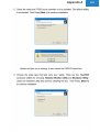
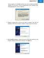
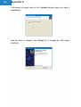
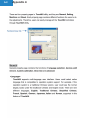
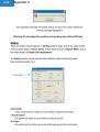
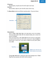
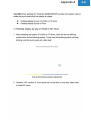
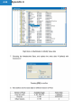
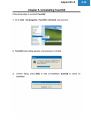
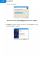
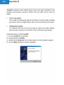
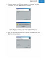
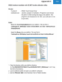
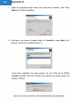
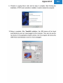
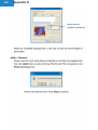
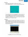
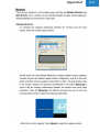
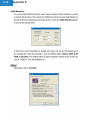
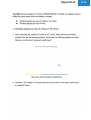
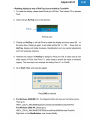
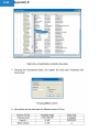
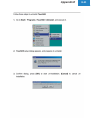
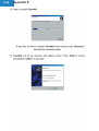
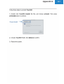
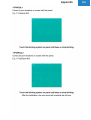
1
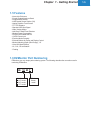
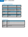
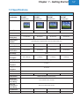
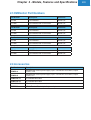
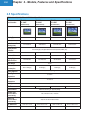
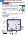
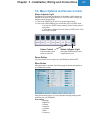
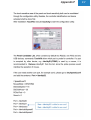
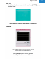
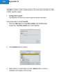
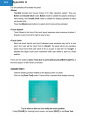
EZMonitor User’s Manual
Manual Part Number EZ-MONITOR-M
Revision A
This page intentionally left blank.
The Most Sensible Automation Products
Direct From the Factory
EZMonitor User’s Manual
Manual Part Number EZ-MONITOR-M
Revision A
WARNING!
Visualization products such as EZAutomation’s EZMonitor are not fail-safe devices and as such must
not be used for protection purposes and or safety in any application. Any reliance on these devices
for equipment or personnel safety is unwarranted. The diagrams and examples in this user manual
are included for illustrative purposes only. The manufacturer cannot assume responsibility or liability
for actual use based on the diagrams and
examples.
TRADEMARKS
This publication may contain references to products produced and/or offered by other companies.
The product and company names may be trademarked and are the sole property of their respective
owners. EZAutomation disclaims any proprietary interest in the marks and names of others.
© COPYRIGHT 2005, EZAUTOMATION, A DIVISION OF AVG AUTOMATION,
ALL RIGHTS RESERVED
No part of this manual shall be copied, reproduced, or transmitted in any way without the prior written
consent of EZAutomation. EZ Automation retains the exclusive rights to all information included in
this document.
MANUFACTURED by AVG AUTOMATION
4140 Utica Ridge Rd. • Bettendorf, IA 52722-1327
MARKETED by EZAutomation
4140 Utica Ridge Rd. • Bettendorf, IA 52722-1327
Phone: 1-877-774-EASY • Fax: 1-877-775-EASY • www.EZAutomation.net
EZ-MONITOR-M
EZ Monitor
TM
EU Information
EZMonitor is manufactured in compliance with European Union (EU) Directives and carries the CE
mark*. EZMonitor has been tested under CE
Test Standard #EN55011, and is submitted for approval. The following information is provided to
comply with EU documentation requirements.
Please NOTE: Products with CE marks perform their required functions safely and
adhere to relevant standards as specified by EU directives provided when used
according to their intended purpose and the instructions provided in this manual.
The protection provided by the equipment may be impaired if the equipment is
not used in accordance with this manual. Only replacement parts supplied by
EZAutomation, or its agents should be used.
Technical
Support
If you need assistance, please call our technical support at 1-877-774-EASY or
FAX us at 1-877-775-EASY.
Warranty
EZAutomation products carry a 2 year warranty against defects in materials and
workmanship. We will replace or repair the defective product at our discretion.
The warranty will be null and voided if the products are abused or used outside
of the product specifications.
Out of Warranty
Repairs
If your EZMonitor is out of warranty, contact EZAutomation’s Customer Service
Department for an evaluation of repair costs @ 1-877-774-EASY. You can
then decide whether it is more economical to proceed with factory repairs or to
purchase a new EZMonitor.
Returns/30-Day
Money Back
Guarantee
EZAutomation products are backed by a 30 day, unconditional, money back
guarantee. You may return the product for any reason for prompt exchange,
credit, or refund (excluding shipping and handling charges). Details of
Warranty and Return procedures are detailed in the Introduction section of the
EZAutomation Catalog.
* Pending
Table of Contents
Cover
Table of Contents
CHAPTER 1 - Getting Started
1.1 Manual Organization…………………………………………….. 1-2
1.2 Product Overview ……………………………………………...... 1-3
1.3 Where to use EZMonitors ………………………………………. 1-4
1.4 Check list to get started…………………………………………. 1-4
1.5 Features…………………………………………………………… 1-5
1.6 EZMonitor Part Numbering……………………………………… 1-5
1.7 EZMonitor Part Numbers………………………………………… 1-6
1.8 Accessories ………………………………………………………. 1-6
1.9 Specifications …………………………………………………….. 1-7
CHAPTER 2 - Models, Features and Specifications
2.1 Features …………………………………………………………. 2-2
2.2 EZMonitor Part Numbering……………………………………… 2-2
2.3 EZMonitor Part Numbers………………………………………... 2-3
2.4 Accessories ……………………………………………………..... 2-3
2.5 Specifications …………………………………………………….. 2-4
CHAPTER 3 - Installation, Wiring and Connections
3.1 Safety Considerations…………………………………………… 3-2
3.2 Installation Considerations……………………………………… 3-3
3.3 Environmental Considerations…………………………………. 3-3
3.4 Electrical Considerations……………………………………….. 3-4
3.5 Connecting EZMonitor to a PC………………………………… 3-6
3.6 Menu Options and Screen Control…………………………….. 3-7
3.7 EZMonitor Mounting…………………………………………….. 3-9
3.8 EZMonitor Cutout Dimensions…………………………………. 3-10
CHAPTER 4 - Maintenance and Troubleshooting
4.1 Maintenance……………………………………………………… 4-2
4.2 Troubleshooting………………………………………………….. 4-6
APPENDIX A ………………………………………………………….. A-1
APPENDIX B ………………………………………………………….. B-1
APPENDIX C ………………………………………………………….. C-1
APPENDIX D ………………………………………………………….. D-1
APPENDIX E ………………………………………………………….. E-1
APPENDIX F ………………………………………………………….. F-1
APPENDIX G ………………………………………………………….. G-1
APPENDIX H …………………………………………………………..H-1
INDEX ……………………………………………………………....... I-1
i
1
Getting Started
In this chapter....
•
•
•
•
•
Manual Organization
Product Overview
Where to Use EZMonitors
Check list to get started
Quick and EZ Start
1-2
Chapter 1 - Getting Started
1.1 Manual Organization
The table below provides an overall description of the topics covered within this manual.
Chapter
Description
1
Chapter 1: Getting Started
Provides Manual Organization and lists what you need to get started to
connect EZMonitor to your PC.
2
Chapter 2: Models, Features and Specifications
Provides you with a table listing the various models, their part numbers and
special features. Lists the important features and hardware specifications for
different models available
3
Chapter 3: Installation, Wiring, and Connections
Provides detailed information on how to connect EZMonitors for service
power, installing video cables, along with Touch Screen communications
wiring. Also provides dimensional and mounting information.
4
Chapter 4: Maintenance and Troubleshooting
Provides information on how to maintain EZMonitors by providing steps to
ensure long life along with Troubleshooting tips.
A
Appendix A: This part of the manual describes in detail the steps
necessary to install touch screen communication drivers for various
operating systems.
Chapter 1 - Getting Started
1-3
1.2 Product Overview
EZMonitor is an industrial strength display that can be used with any standard,
commercial or industrial computer. All you need is a standard VGA port to connect
EZMonitor to your computer. EZMonitor offers display and touchscreen solution for
industrial environments not suited for standard monitors. The following will provide
you a brief overview of EZMonitors.
Powder Coated
Aluminum Bezel
Slim yet sturdy front bezel
with industrial hardened studs
pressed-in.
Menu Options and Screen Control
Adjust display settings with easy to navigate
menu buttons.
NEMA 4, 4X front
Allows optimum protection
against Hosedown and
Splashing Water with Corrosion
Resistance.
Power Control
External power control button
on rear end.
Analog Resistive
Touch Screen
Aluminum Chassis
All metallic aluminum chassis
with ventilation holes for
minimal heat buildup.
Reliable touch screen for tough
industrial environments, Glove
Proof!
TFT Color Displays
Ultra crisp picture quality with
wide viewing angles.
Touch Screen Port
Communication port for
EZMonitors with Touch
Screen.
Agency Approvals
UL, CUL, and CE (pending)
6’ Industrial VGA Cable
VGA Port for Signal Input
Standard 6’ length VGA cable
included with every EZMonitor.
12 VDC Input Power
6’ Touchscreen Communication Cable
Standard 6’ long touchscreen USB cable included with
every Touchscreen model EZMonitor. Touchscreen
Drivers included for easy installation with Windows 95,
98, 2000, NT, ME, CE, XP and DOS.
Take advantage of your existing 12VDC power supply in
your system. EZMonitor is shipped with two 20 ft. wires to
connect to your 12 VDC. Removable Phoenix Terminal Block
is provided for the power wiring and is shipped with each
EZMonitor. For 110-240 VAC applications, we can supply wall
plug-in 12 Volt power supplies also.
1-4
Chapter 1 - Getting Started
1.3 Where to use EZMonitors
Use EZMonitors to display information from your PC any where on your plant floor. It has excellent noise,
shock, and vibration ratings. Analog resistive touch screen (on select models) allows user input with the highest
resolution and makes user input easier then ever. With EZMonitors you don’t have to buy standard monitors and
enclose them in special housings just to survive thermal shock and water-proofing. EZMonitors have Nema 4,4x
rated front bezel to provide the strongest protection from water and dusty environments.
1.4 Check list to get started
Before you start installing your EZMonitor, take a couple of moments and verify that you have all the following
for quick and easy installation of your EZMonitor:
-
EZMonitor
12 VDC Power Input*
Video Cable**
Touch Screen communication cable**
Appropriate touch screen driver for your operating system (e.g. Win 95/98, Win XP etc)**
*
NOT included with the purchase of EZMonitors.
All EZMonitors require a 12VDC power input for operation.
110/220 VAC to 12 VDC power supply available separately
(P/N EZ-MPS-A; EZ-MPS-B)
**
Every EZMonitor is shipped with a standard 6’ Video Cable for operation with most of the computers.
Every EZMonitor with touch screen is also shipped with a 6’ touch screen communications cable to
connect with a standard PC (USB cable).
This manual on CD also has all the Touchscreen drivers.
Chapter 1 - Getting Started
1.5 Features
• Nema 4,4x Enclosure
• Powder Coated Aluminum Bezel
• Rugged Metal Chassis
• Hard Coated Screen Surface (3H)
• Analog Resistive Touch Screen
• TFT LCD Displays
• Standard VGA Input Signal
• Wide Viewing Angles
• Anti-Glare Treated Front Polarizer
• Minimal Power Consumption
• 40-50K Hours Rated Half Life
• 12VDC Power Input
• Electrical Noise Immunity
• External Buttons for Power and Display Control
• Minimal Mounting Depth (Slim Design), 1.9”
• Ultra LOW Heat Build-up
• UL, CUL, CE certification*
* Pending
1.6 EZMonitor Part Numbering
EZMonitors use very simple part numbering system. The following describes the convention used in
numbering EZMonitors.
EZ- 10 M T
10
12
15
17
10” model
12” model
15” model
17” model
T Touch
Screen
model
1-5
1-6
Chapter 1 - Getting Started
1.7 EZMonitor Part Numbers
Part Number
Description
Enclosure
EZ-10M
10” EZMonitor
Nema 4,4x
EZ-10MT
10” EZMonitor with Touch Screen
Nema 4,4x
Part Number
Description
Enclosure
EZ-10M
10” EZMonitor
Nema 4,4x
EZ-10MT
10” EZMonitor with Touch Screen
Nema 4,4x
Part Number
Description
Enclosure
EZ-10M
10” EZMonitor
Nema 4,4x
EZ-10MT
10” EZMonitor with Touch Screen
Nema 4,4x
Part Number
Description
Enclosure
EZ-10M
10” EZMonitor
Nema 4,4x
EZ-10MT
10” EZMonitor with Touch Screen
Nema 4,4x
1.8 Accessories
Part Number
Description
EZ-MPS-A
Molded design cord set power supply: Input: 110V-240VDC at 50-60Hz, Output:
12VDC, 3.3A
EZ-MPS-B
Molded design cord set power supply: Input: 110V-240VDC at 50-60Hz, Output:
12VDC, 5A
EZ-MVCBL-10
10’ shielded video cable
EZ-MVCBL-25
25’ shielded video cable
EZ-MVCBL-50
50’ shielded video cable
EZ-????
?????
Chapter 1 - Getting Started
1.9 Specifications
EZMonitor 10”, 12”, 15” and 17” Model Specifications
Part Number
Display Type
EZ-10M
EZ-10MT
EZ-12M
EZ-12MT
EZ-15M
EZ-15MT
EZ-17M
EZ-17MT
(Touchscreen)
(Touchscreen)
(Touchscreen)
(Touchscreen)
10.4” SVGA TFT Color
12.1” SVGA TFT Color
Enclosure
Active Screen Size
(Viewing Area)
Contrast Ratio
Display Brightness
/Half Life Hours
211.2x158.4mm
246x184.5mm
304.1x228.1mm
800 x 600
800 x 600
1024 x 768
1280 x 1024
400:1
200:1
350:1
350:1
220 nits/40,000
300 nits/50,000
250 nits/40,000
250 nits/50,000
15 Watt (typ.)
30 Watt (typ.)
12VDC
Total 10 Watt (typ.)
12 Watt (typ.)
Agency Approval
UL, CUL, CE (pending)
Operating
Temperature
0° to 60°C
Storage
Temperature
-20° to 65°C
Humidity
Life Time
337.9x270.3mm
Hard Coating (3H), Anti-glare treatment of the front polarizer, HAZE (13%)
Input Voltage
Power
Consumption
17” SXGA TFT Color
NEMA 4, 4X Front plate
Display Surface
Treatment
Resolution
15” XGA TFT Color
10-90% RH
4 0,000 Hours
Electrical Noise
50,000 Hours
40,000 Hours
50,000 Hours
NEMA ICS showering arc approval pending
Vibration with
2.0G, 0.37oct/min 3 axis, 1 hour/axis
Terminal Block
Power Wiring
Shock with
20G, 2ms one shock of each six faces
Terminal Block
Power Wiring
Ext. Dimensions
Weight
12.10” x 9.7” x 1.75”
13.45” x 10.50” x 2.12”
16.25” x 12.50 x 1.9”
18.25” x 14.50” x 2.18”
5.5 lbs.
6.1 lbs
7.0 lbs
10.51 lbs
1-7
1-8
Chapter 1 - Getting Started
This page intentionally left blank.
2
Models, Features
and Specifications
In This Chapter....
• Features
• EZMonitor Part Numbering
• EZMonitor Part Numbers
• Accessories
• Specifications
2-2
Chapter 2 - Models, Features and Specifications
2.1 Features
• Nema 4,4x Enclosure
• Powder Coated Aluminum Bezel
• Rugged Metal Chassis
• Hard Coated Screen Surface (3H)
• Analog Resistive Touch Screen
• TFT LCD Displays
• Plug-n-Play Setup
• Standard VGA Input Signal
• Wide Viewing Angles
• Anti-Glare Treated Front Polarizer
• Minimal Power Consumption
• 40-50K Hours Rated Half Life
• 12VDC Power Input
• Electrical Noise Immunity
• External Buttons for Power and Display Control
• Minimal Mounting Depth (Slim Design), 1.9”
• Ultra LOW Heat Build-up
• UL, CUL, CE certification*
* Pending
2.2 EZMonitor Part Numbering
EZMonitors use very simple part numbering system. The following describes the convention used in
numbering EZMonitors.
EZ- 10 M T
10
12
15
17
10” model
12” model
15” model
17” model
T Touch
Screen
model
Chapter 2 - Models, Features and Specifications
2.3 EZMonitor Part Numbers
Part Number
Description
Enclosure
EZ-10M
10” EZMonitor
Nema 4,4x
EZ-10MT
10” EZMonitor with Touch Screen
Nema 4,4x
Part Number
Description
Enclosure
EZ-10M
10” EZMonitor
Nema 4,4x
EZ-10MT
10” EZMonitor with Touch Screen
Nema 4,4x
Part Number
Description
Enclosure
EZ-10M
10” EZMonitor
Nema 4,4x
EZ-10MT
10” EZMonitor with Touch Screen
Nema 4,4x
Part Number
Description
Enclosure
EZ-10M
10” EZMonitor
Nema 4,4x
EZ-10MT
10” EZMonitor with Touch Screen
Nema 4,4x
2.4 Accessories
Part Number
Description
EZ-MPS-A
Molded design cord set power supply: Input: 110V-240VDC at 50-60Hz, Output:
12VDC, 3.3A
EZ-MPS-B
Molded design cord set power supply: Input: 110V-240VDC at 50-60Hz, Output:
12VDC, 5A
EZ-MVCBL-10
10’ shielded video cable
EZ-MVCBL-25
25’ shielded video cable
EZ-MVCBL-50
50’ shielded video cable
EZ-TERM3
3 Point Terminal Block adapter for power input
2-3
2-4
Chapter 2 - Models, Features and Specifications
2.5 Specifications
EZMonitor 10”, 12”, 15” and 17” Model Specifications
Part Number
Display Type
EZ-10M
EZ-10MT
EZ-12M
EZ-12MT
EZ-15M
EZ-15MT
EZ-17M
EZ-17MT
(Touchscreen)
(Touchscreen)
(Touchscreen)
(Touchscreen)
10.4” SVGA TFT Color
12.1” SVGA TFT Color
Enclosure
Active Screen Size
(Viewing Area)
Contrast Ratio
Display Brightness
/Half Life Hours
211.2x158.4mm
246x184.5mm
304.1x228.1mm
800 x 600
800 x 600
1024 x 768
1280 x 1024
400:1
200:1
350:1
350:1
220 nits/40,000
300 nits/50,000
250 nits/40,000
250 nits/50,000
15 Watt (typ.)
30 Watt (typ.)
12VDC
Total 10 Watt (typ.)
12 Watt (typ.)
Agency Approval
UL, CUL, CE (pending)
Operating
Temperature
0° to 60°C
Storage
Temperature
-20° to 65°C
Humidity
Life Time
337.9x270.3mm
Hard Coating (3H), Anti-glare treatment of the front polarizer, HAZE (13%)
Input Voltage
Power
Consumption
17” SXGA TFT Color
NEMA 4, 4X Front plate
Display Surface
Treatment
Resolution
15” XGA TFT Color
10-90% RH
4 0,000 Hours
Electrical Noise
50,000 Hours
40,000 Hours
50,000 Hours
NEMA ICS showering arc approval pending
Vibration with
2.0G, 0.37oct/min 3 axis, 1 hour/axis
Terminal Block
Power Wiring
Shock with
20G, 2ms one shock of each six faces
Terminal Block
Power Wiring
Ext. Dimensions
Weight
12.10” x 9.7” x 1.75”
13.45” x 10.50” x 2.12”
16.25” x 12.50 x 1.9”
18.25” x 14.50” x 2.18”
5.5 lbs.
6.1 lbs
7.0 lbs
10.51 lbs
3
Installation, Wiring and
Connections
In this chapter....
•
•
•
•
•
•
•
Safety Considerations
Installation Considerations
Environmental Considerations
Electrical Considerations
Wiring and Connections
Connecting EZMonitor to a PC
Mounting Cutouts
3-2
Chapter 3 - Installation, Wiring and Connections
3.1 Safety Considerations
Please follow all applicable local and national codes to ensure maximum
safety of the equipment and personnel. The installation and operational
environment must be maintained per the latest revision of these codes.
You are responsible to determine the codes to be followed, and to verify
the compliance of equipment, installation, and operation with the latest
revision of these codes.
Plan for Safety
It is an absolute must to follow all applicable sections of:
• The National Fire Code
• The National Electrical Code (NEC)
• The National Electrical Manufacturer’s Association (NEMA) codes.
Local regulatory and government offices usually provide excellent help to
determine which codes and standards are necessary for safe installation
and operation.
Safety Techniques
Safety is the most important element of a proper system installation.
Adhering to these safety considerations ensures the safety of yourself
and others, as well as the condition of your equipment. We recommend
reviewing the following safety considerations:
1) Disconnecting Main Power
The main power switch should be easily accessible to the operators
and maintenance personnel. It is important to make sure that all other
sources of power including pneumatic and hydraulic are de-energized
before starting the work on a machine or process controlled by a
PLC or a PC.
2) Safety Circuits
Most of the machines are installed with safety circuits, like Limit
switches, Emergency stop push buttons, and Interlocks. These circuits
should always be hard-wired directly to the PLC. These devices must
be wired in series so that when any one device opens, the PLC is
automatically de-energized. This removes power to the machine.
These circuits should not be altered in any case, since serious injury
or machine damage could result.
3) Fail-Safe Operation
Our products are not fault-tolerant and are not designed or intended
for use as on-line control equipment in hazardous environments
requiring fail-safe performance, such as in operation of nuclear
facilities, aircraft navigation or communication systems, air traffic control,
direct life-support machines, weapons systems, clutch control systems on
presses, in which the failure of the product could lead directly to death,
personal injury or severe physical or environmental damage. External
fail safe and/or redundant components are required to make your control
system Fail-safe.
Chapter 3 - Installation, Wiring and Connections
3-3
3.2 Installation Considerations
EZAutomation products have been designed and tested for operation in
the most demanding industrial environments. Modern solid-state industrial controls are complex electronic equipment that operate at low levels
of voltage and current, coexisting with components that operate at much
higher levels of power. The difference in operating power characteristics
between the high and low power control devices creates the possibility of
unwanted signals being generated causing interference. The interference,
which is a by-product of electrical noise, is not present at all times. However, it appears at random and during brief periods of time it can cause
disruptions and errors in the operation of a control system.
Enhancement of a system’s noise level immunity, and its tolerance to
other environmental hazards can be accomplished by following proper
system installation guidelines. The recommendations are of a general
nature and constitute good industrial installation practice.
General Environmental Installation Considerations
Avoid installing EZMonitors in areas where the following conditions
may exist:
• Environmental temperatures above or below those specified for EZMonitors.
• Prolonged exposure to humidity and liquids which may be sprayed or
splashed on the equipment.
• Dusty environments where airborne particles may accumulate on equipment causing reduction of heat dissipation, and reduction in effective
electrical spacing between components.
• Areas of excessive vibration.
• Areas of high-radiated electrical noise, such as near fields of transmitting antennas and areas in close proximity of arc welding stations.
3.3 Environmental Considerations
The following table lists the environmental specifications that generally
apply to the EZMonitors.
Parameter Ratings
Operating Temperature
Storage Temperature
Humidity
Vibration Resistance
Shock Resistance
Electrical Noise
Atmospheric Conditions
0 to 60 °C
-20 to 65 °C
10 to 90% Relative Humidity,
Non-condensing
5 to 55 Hz, 2.0G, 0.37oct/min 3 axis,
1 hour/axis
20G, 2ms one shock of each six faces
NEMA ICS 2-230 Showering Arc, ANSI
C37.90a SWC, Level C Chattering Test
Non-corrosive gases
3-4
Chapter 3 - Installation, Wiring and Connections
Agency Approvals
Your application may require Agency approval. EZPLC’s agency
approvals are:
• UL (Underwriter’s Laboratories, Inc)*
• CUL (Canadian Underwriter’s Laboratories, Inc)*
• CE (EU Certification)*
*Approvals in process. Check our website www.EZAutomation.net for
the latest information.
3.4 Electrical Considerations
Understanding Electrical Noise and Shielding of Cables
This section will provide you with a very basic understanding of Electrical
Noise and how to keep it away from EZMonitors.
Source of Electrical Noise
Industrial plants have a number of generators of electrical noise or
sometimes also referred to as Radio Frequency Interference or RFI.
Anytime an inductive load like a motor, motor starter, or solenoid is
turned off, it generates a burst of excess energy that has to flow back
to ground, just like electrical energy from a lightening storm has to flow
back to Earth. Other sources are RF Welders or Radio Transmitters.
RFI is short bursts of electrical energy at very high frequencies.
Cabinets
Equipment cabinets usually incorporate one or two doors and/or hinged
cabinet panels. In addition, sub-panels may be utilized on those electronic
controls and electromechanical items that are mounted. The goal here is
to create a medium for mounting the equipment and ensure grounding of
the control’s chassis to it. Relying on door hinges and swinging panels for
good metallic bond between hinged parts and the main body of the cabinet
does not insure adequate grounding. That is why the use of ground straps
is recommended. RFI enters electronic controls in two ways:
• Radiated RFI
• Conducted RFI
For most practical purposes, electronic devices, unless sitting right next to
a powerful RFI transmitter, will not be affected by noise because air space
severely attenuates such interference. On the other hand, conducted RFI
travels over conductive surfaces such as power supply wires, electrical
wiring of field devices, and worst of all; improper ground planes.
It is a common practice to isolate the sensitive electronics from RFI by
providing Transformer or Choke Isolation on the Power Supply.
Cabling, Shielding, and Grounding
It is vital for the reliable operation of any electronic device to have any of
its metallic surface well grounded to Earth. This not only provides for safe
operation, it also will drain out any conducted RFI to Earth, away from the
electronics. Obviously, the metal cabinet housing the EZMonitor should
also be well grounded. The following section will detail these procedures.
Power cables and communication cables should all be separate so that
they do not couple the conducted RFI on any of these wires/cables.
Chapter 3 - Installation, Wiring and Connections
3-5
Cabinet Grounding
Equipment cabinets usually incorporate one or two doors and/or hinged
cabinet panels. In addition, sub-panels may be utilized on those electronic
controls and electromechanical items that are mounted.
The goal is to create a medium for mounting the equipment and ensure
grounding of the control’s chassis to it. Relying on door hinges and swinging panels for good metallic bond between hinged parts and the main body
of the cabinet does not insure adequate grounding. That is why the use of
ground straps is recommended. The equipment enclosures are generally
either painted or anodized. It is imperative that the equipment chassis
are grounded. Not only is this good safety practice, but it also helps noise
immunity problems. Mounting of painted or anodized enclosures to like
surfaces does not insure good metallic contact between the equipment
chassis and cabinet. The use of star washers when mounting the EZMonitors, or other components, provides sufficient grounding on the panel.
Cabinet Door Grounding Straps
Cabinet Wiring
The wiring of the EZMonitor to the “field” outside the cabinet must be by
design. The wiring cannot be random in order to get the various points of
the cabinet and the “field” electrically connected.
Some general rules that apply in most situations are:
• Provide a separate power source to electronic controls and keep this
power buss away from any I/O power.
• The cabinet should be wired with a safety ground (the main safety
ground wire gauge is determined by the cabinet’s total current
consumption) and in accordance with all electrical code
requirements.
• Once the cabinet doors, stationary sub-panels and swing-out subpanels
have been “strapped” to the main cabinet, it is not necessary to
run safety ground wires from the equipment chassis terminals to the
main safety ground connection.
• The safety ground terminal of each component can, and should be,
connected with the shortest wire possible, to the cabinet or sub-panel
frame.
• Plan the wiring routing. Keep all switched power in separate ducts and
if there is AC and DC power being switched, keep the wiring of each
branch separate from all wires and cables carrying low level signals.
• Keep all three phase power outside of the cabinet, but if it becomes
necessary, keep the runs as short as possible and maintain the maximum possible distance between the three phase buss and all other
wiring.
• Primary power leads to the control equipment (Base power terminals)
should be made with a two wire twisted cable with approximately 12 turns
per foot. Length of these cables should be kept to the minimum and to
the greatest extent possible such cable runs should be kept separate
from other wiring.
• In the case of AC powered equipment, the primary power should be
provided separately from the power source used for I/O control.
3-6
Chapter 3 - Installation, Wiring and Connections
EZ Monitor
TM
Quick and EZ Wiring and Set-up Reference
3.5 Connecting EZMonitor to a PC
In order to connect your EZMonitor to your PC just follow the easy steps below:
1. Install appropriate TouchScreen communication drivers on your PC (for select
models – Refer to appendix A for details for every OS available) See reverse side
2. Connect VGA Cable to EZMonitor and your PC
3
2
EZMonitors have a standard VGA port built-in as shown in the image below. This VGA port
can be used for connecting to any standard PC with a VGA output port. It has a standard high
density VGA female connector (15 pin). The VGA port is Plug-n-Play where all you have to do
is to connect to the VGA port of your PC for operation. Every EZMonitor is also shipped with
6’ standard VGA cable to connect to a PC (IBM or compatible). Since it utilizes standard VGA
cable, you can also utilize your existing VGA cables if desired.
3. Connect TouchScreen communication cable to EZMonitor and your PC
(for select models)
2
3
Touch Screen models of EZMonitors come with a Touch Screen communication port. This port has a 5 pin connector which is used
to connect to a USB port of a PC with the Touch Screen communications cable provided. Once you have connected your PC to the
Touch Screen communications port of EZMonitor, you have to install Touch Screen communication drivers (included on CD-ROM).
See appendix A for details on how to install and calibrate the Touch Screen for your EZMonitor
4. Apply power to EZMonitor
4
All EZMonitors require a 12VDC power input for operation. The power input is supplied to EZMonitors via a standard power input
jack as shown in the image below.
5. Calibrate your TouchScreen (for select models- Refer to appendix A for more details)
Mounting Studs
Power LED indicator
Power ON/OFF
Button
Display Setup
Buttons
VGA Port
Touch Screen
Connector
Shipped with 6’ cable
10, 25 and 50’ optional
2
4
12VDC Power
Shipped with 20’ 18 AWG
wire harness.
Optional 110 VAC to 12 VDC
power supply available
(P/N: EZ-MPS-A, EZ-MPS-B)
Black
Red
3
Shipped with 6’
cable with USB
connector at the
other end.
Optional 10’
extender cable
available
Chapter 3 - Installation, Wiring and Connections
3-7
3.6 Menu Options and Screen Control
Status Indicator Light
The Status LED provides an indication of unit status. It will illuminate as
GREEN when power is applied to the unit. If the LED does not light, this
indicates one of the two things
1. There is NO POWER to the unit or the power supply failed
2. There is NO VGA SIGNAL to the unit and the unit is in SLEEP mode.
- If the unit is in SLEEP mode, pressing “Power” button will turn
it back ON
- If VGA signal is applied to the unit while in SLEEP mode, it will
also turn the unit ON
Power Control
Status Indicator Light
External power control
button on rear end
Illuminates GREEN when power
is applied to the unit.
Power Button
The power button can be used to turn the EZMonitor ON and OFF.
Menu Button
When this button is pressed, the following pop-up window will appear on
your EZMonitors screen.
Using the following menus, you can adjust the following settings under
each Menu for your EZMonitor.
Picture Menu
- Backlight
- Brightness
- Contrast
- H position
- V position
- Phase
- Frequency
3-8
Chapter 3 - Installation, Wiring and Connections
Advanced Menu
- Sharpness
- Color Matrix
- Color Temp
- User Red
- User Green
- User Blue
- More options
- User red c1
- User red c2
- User green c1
- User green c2
- User blue c1
- User blue c2
Options Menu
- Osd
- Language
- Dpms
- Source scan
- Blank color
- Auto adjust
Utility Menu
- osd timeout
- factory init
UP / Down / Right / Left Button
These buttons are used for navigation and selection in a Menu once
invoked.
Chapter 3 - Installation, Wiring and Connections
3-9
3.7 EZMonitor Mounting
NOTE: All necessary
mounting hardware is
provided with EZMonitors.
Use the studs and nuts provided
to properly secure the unit on the
mounting surface.
EZMonitors can be mounted using stud mounting procedure as shown in
the image below. In order for you mount EZMonitor in your control cabinet, you need to pay close attention to cutout dimensions of the EZMonitor for proper installation.
EZMonitor mounting
in a NEMA4 rated
enclosure.
Allow 1-inch
clearance
between rear
of panel and
enclosure
Allow 4-inches
for panel X-Y
clearance.
CAUTION! Mount
EZMonitor on a VERTICAL
SURFACE only to ensure
proper cooling of the unit.
3-10
Chapter 3 - Installation, Wiring and Connections
3.8 EZMonitor Cutout Dimensions
10” EZMonitor Cutout Dimensions
All the necessary mounting hardware is provided with the unit. Use the 10 studs and 10 nuts with captive washers to secure the
unit on the mounting surface. Dimensions are provided in inches and millimeters, where millimeters appear in [ ].
Chapter 3 - Installation, Wiring and Connections
12” EZMonitor Cutout Dimensions
All the necessary mounting hardware is provided with the unit. Use the 12 studs and 12 nuts with captive washers to secure
the unit on the mounting surface. Dimensions are provided in inches and millimeters, where millimeters appear in [ ].
3-11
3-12
Chapter 3 - Installation, Wiring and Connections
15” EZMonitor Cutout Dimensions
All the necessary mounting hardware is provided with the unit. Use the 14 studs and 14 nuts with captive washers to secure the
unit on the mounting surface. Dimensions are provided in inches and millimeters, where millimeters appear in [ ].
Chapter 3 - Installation, Wiring and Connections
3-13
17” EZMonitor Cutout Dimensions
16.150
[410.21]
8.075
[205.11]
All the necessary mounting hardware is provided with the unit. Use the 14 studs and 14 nuts with captive washers to secure the
unit on the mounting surface. Dimensions are provided in inches and millimeters, where millimeters appear in [ ].
3-14
Chapter 3 - Installation, Wiring and Connections
This page intentionally left blank.
4
Maintenance and
Troubleshooting
In This Chapter....
•
•
•
•
Maintenance
EZMonitor’s TouchScreen Chemical Compatibility
TouchScreen Cleaning
Troubleshooting
4-2
Chapter 4 - Maintenance and Troubleshooting
4.1 Maintenance
Backlight Bulb
Generally, backlight bulb far exceeds the manufacturer’s expected life.
The manufacturer’s expected half-life rates are provided in the table
below.
Tip:
EZMonitor Model #
Manufacturer’s Expected
Bulb Half-Life
EZ-10M
40,000 Hrs
EZ-10MT
40,000 Hrs
EZ-12M
50,000 Hrs
EZ-12MT
50,000 Hrs
EZ-15M
40,000 Hrs
EZ-15MT
40,000 Hrs
EZ-17M
50,000 Hrs
EZ-17MT
50,000 Hrs
Take advantage of your PC’s screen saver feature to turn
the monitor off when not in use. This will significantly
extend the life of back light of your EZMonitor.
Precautions
To insure the longevity and effectiveness of EZMonitors, please take note
of the following precautions:
- Do not press any sharp object against the screen
- Do not strike the unit with hard objects
- Do not press the screen with excessive force
- Once the unit is mounted and power is applied to it, do not
place any objects over the ventilation slots. This will
result in heat buildup and may damage the unit
Chapter 4 - Maintenance and Troubleshooting
Standard Bezel
4-3
EZMonitor’s Chemical Compatibility
The TouchScreen models of EZMonitor have a Polyester surface. The following list is
provided to make you aware of the general compatibility between chemicals that may
be present in your work environment and the polyster surface of the TouchScreen. Use
the hat to determine those chemicals which are safe to use around your EZMonitor
and those which may harm the TouchScreen of EZMonitors. This list rates the
chemicals as: E – Excellent, G – Good, F – Fair, N – Not Recommended
Because the rating are for ideal conditions at 57 deg C, consider all factors when
evaluating your application.
Chemical
Acetone
Auto fuel
Auto Hydraulics
Butyl Cellosolve
Chloroform
Coffee
Cyclohexanone
Downy
Dioctyl Phthalate
Ethanol
Fantastic
Grape Juice
Hexane
Isopropyl Alcohol
Lemon Juice
Methylene Chloride
Mineral Acids (strong)
Mustard
Phenol
Sodium Hydroxide (strong)
Spray ‘N Wash
Toluene
Top Job
Triethanolamine
Wisk
Zinc Chloride
Rating
G
E
E
E
G
E
N
E
G
E
E
E
E
E
E
N
G
G
N
F
E
E
E
G
F
E
Chemical
Aniline
Auto lubricants
Bromine (wet)
Butyl Ether
Clorox
Cupric Sulfate
Cyclohexanol
Diethyl Ether
Ethyl Acetate
Ethylene Chloride
Formula 409
Heptane
Hydrogen Peroxide
Ketchup
MEK
Mineral Acids (dilute)
Mr. Clean
Naphtha
Sodium Hydroxide (dilute)
Sodium Hypochlorite
Tea
Tomato Juice
Trichloroacetic acid
Vinegar
Xylene
Rating
G
E
N
G
E
E
E
G
E
G
E
E
N
E
F
E
E
G
G
E
E
E
F
E
E
4-4
Chapter 4 - Maintenance and Troubleshooting
Slim Bezel
EZMonitor’s Chemical Compatibility
The models of EZMonitor without have a Polycarbonate surface. The following list is
provided to make you aware of the general compatibility between chemicals that may
be present in your work environment and the polyester surface of the TouchScreen. Use
the hat to determine those chemicals which are safe to use around your EZMonitor and
those which may harm the TouchScreen of EZMonitors. This list rates the chemicals as:
E – Excellent, G – Good, F – Fair, N – Not Recommended
Because the rating are for ideal conditions at 57 deg C, consider all factors when
evaluating your application.
Chemical
Acetaldehyde
Acetic Acid @ 5%
Acetone
Acrylonitrile
Alanine
Alum. Hydroxide
Amino Acids
Ammonium Acetate
Ammonium Hydroxide @ 5%
Ammonium Oxalate
n-Amyl Acetate
Aniline
Benzene
Benzyl Acetate
Bromine
Bromoform
n-Butyl Acetate
sec-Butyl Alcohol
Butyric Acid
Calcium Hypochlorite
Formic Acid @ 3%
Formic Acid @ 99%
Gasoline
Glycerin
Hexane
Hydrochloric Acid @ 20%
Hydrofluoric Acid @ 5%
Hydrogen Peroxide @ 5%
Hydrogen Peroxide @ 90%
Isopropyl Acetate
Isopropyl Benzene
Lactic Acid @ 3%
Methoxyethyl Oleate
Methyl Ethyl Ketone
Methyl Propyl Ketone
Mineral Oil
Nitric Acid @ 50%
Nitrobenzene
Orange Oil
Carbazole
Carbon Tetrachloride
Cellosolve Acetate
Chlorine @ 10% moist
p-Chloroacetophenone
Rating
N
G
N
N
N
N
E
E
N
E
N
N
N
G
F
N
N
F
N
N
G
F
F
E
N
F
F
E
E
N
N
G
N
N
N
G
F
N
F
N
N
N
F
N
Chemical
Acetamide
Acetic Acid @ 50%
Acetonitrile
Adipic Acid
Allyl Alcohol
Aluminum Salts
Ammonia
Ammonium Gloclate
Ammonium Hydroxide @30%
Ammonium Salts
Amyl Chloride
Benzaldehyde
Benzoic Acid
Benzyl Alcohol
Bromobenzene
Butadiene
n-Butyl Alcohol
tert-Butyl Alcohol
Calcium Hydroxide
Formaldehyde @ 40%
Formic Acid @ 50%
Fuel Oil
Glacial Acetic Acid
n-Heptane
Hydrochloric Acid @ 5%
Hydrochloric Acid @ 35%
Hydrofluoric Acid @ 48%
Hydrogen Peroxide @ 30%
Isobutyl Alcohol
Isopropyl Alcohol
Kerosene
Lactic Acid @ 85%
Methyl Alcohol
Methyl Isobutyl Ketone
Methylene Chloride
Nitric Acid @ 10%
Nitric Acid @ 70%
n-Octane
Ozone
Carbon Disulfide
Cedarwood Oil
Chlorine @ 10% in air
Chloroacetic Acid
Chloroform
Rating
N
G
N
E
F
G
N
F
N
G
N
N
G
G
N
N
F
F
N
G
G
G
N
G
E
N
N
E
G
E
E
G
F
N
N
G
N
F
G
N
F
G
N
N
Chapter 4 - Maintenance and Troubleshooting
Chemical
Chromic Acid @ 10%
Cinnamon Oil
Cresol
Decalin
p-Dichlorobenzene
Diethyl ether
Diethyl Malonate
Diethylene Glycol Ethyl Ether
Dimethyl Sulfoxide
Dipropylene Glycol
Ethyl Acetate
Ethyl Alcohol @ 40%
Ethyl Benzoate
Ethyl Chloride Liquid
Ethyl Lactate
Ethylene Glycol
Ethylene Oxide
Fluorine
Perchloric Acid
Phenol Crystals
Phosphoric Acid @ 85%
Potassium Hydroxide @ 1%
Propane Gas
Propylene Oxide
Resorcinol @ 5%
Salicylic Acid Powder
Salt Solutions Metallic
Silver Nitrate
Sodium Hydroxide @ 1%
Sodium Hypochlorite @ 15%
Sulfuric Acid @ 6%
Sulfuric Acid @ 60%
Sulfur Dioxide Liquid
Sulfur Salts
Tetrahydrofuran
Toluene
Trichloroethane
Triethylene Glycol
Turpentine
Urea
Xylene
Rating
N
F
N
N
N
N
N
N
N
F
N
G
N
N
N
F
N
F
N
N
G
N
N
F
F
G
E
E
N
F
E
F
G
N
N
N
N
G
N
N
N
Chemical
Chromic Acid @ 50%
Citric Acid @ 10%
Cyclohexane
o-Dichlorobenzene
Diethyl Benzene
Diethyl Ketone
Diethylene Glycol
Dimethylformamide
1, 4-Dioxane
Ether
Ethyl Alcohol
Ethyl Benzene
Ethyl Butyrate
Ethyl Cyanoacetate
Ethylene Chloride
Ethylene Glycol Methyl Ether
Fluorides
Formaldehyde
Perchloroethylene
Phosphoric Acid @ 5%
Pine Oil
Potassium Hydroxide conc.
Propylene Glycol
Resorcinol sat.
Salicylaldehyde
Salicylic Acid sat.
Silver Acetate
Sodium Acetate sat.
Sodium Hydroxide @ 50%+
Stearic Acid Crystals
Sulfuric Acid @ 20%
Sulfuric Acid @ 98%
Sulfur Dioxide dry
Tartaric Acid
Thionyl Chloride
Tributyl Citrate
Trichloroethylene
Tripropylene Glycol
Undecyl Alcohol
Vinylidene Chloride
Zinc Stearate
Rating
N
G
G
N
N
N
F
N
F
N
G
N
N
N
N
N
E
G
N
E
E
N
F
F
F
G
G
G
N
G
G
N
G
G
N
N
N
G
F
N
E
TouchScreen Cleaning
EZMonitor TouchScreen has a scratch resistant coating. This adds a slight chemical barrier
to the screen, but the screen’s primary purpose is to protect the screen from abrasion. The
TouchScreen should be cleaned when necessary with warm soapy water Only.
4-5
4-6
Chapter 4 - Maintenance and Troubleshooting
4.2 Troubleshooting
Problem: Unit does not power up
Action:
1. Check to confirm a 12 VDC power to EZMonitor. Make sure
that correct polarity is observed as mentioned on page X
2. When power is applied to the unit, the status indicator LED
should turn on GREEN.
- If power is present to the unit but NO VGA signal is
applied, the unit will go in SLEEP mode.
- If the unit is in SLEEP mode, pressing “Power”
button will turn it back ON
- If VGA signal is applied to the unit while in SLEEP
mode, it will also turn the unit ON
Problem: Unit is Blank when turned ON
Action:
1. When the unit is turned on the status indicator light should
be turned on GREEN.
2. Check to confirm that the VGA cable is connected properly
on both ends, EZMonitor and your PC.
3. If cables are connected properly, make sure that the PC
is turned on and there is signal present in VGA cable
connected to the EZMonitor.
4. Either disconnect power to EZMonitor, or turn it off using the
“On/Off” push button at the back of the unit.
5. Reapply power, or turn it on using the “On/Off” push button
to display the VGA signal being sent to it via the VGA cable.
Problem: The display area is not aligned / image is
not centered on the screen
Action:
1. The image display setup and control buttons are located at
the back of the unit.
2. Press “Menu” button which will pop-up a window on the
screen of the unit.
Note: “Menu” function will only work when the unit is
displaying an image sent over VGA port
3. Using the navigation keys “Up/Down” and “Right/left” select
the appropriate settings of the EZMonitor which you wish to
adjust
4. Once you have change the settings as desired, press
“Menu” button twice to exit from the window and return to
normal operation
Chapter 4 - Maintenance and Troubleshooting
4-7
Problem: TouchScreen is not working
Action:
1. Check to make sure that the TouchScreen communication
cable is connected properly on EZMonitor and the USB port
of your computer.
2. In order to use the functionality of TouchScreen, you must
install the proper drivers for the OS (operating system)
running on the PC connected to EZMonitor.
3. All the TouchScreen drivers for available OS are present on
the CD-ROM included with your EZMonitor.
4. Refer to Appendix A for detailed instructions on how to
install TouchScreen drivers for all the OS supported by
EZMonitors TouchScreen.
Problem: TouchScreen out of Calibration
Action:
1. Once You have installed TouchScreen drivers on the
PC connected to EZMonitor, you must calibrate the
TouchScreen using “Touchkit” configuration utility.
2. “Touchkit” configuration utility is installed on your PC when
you install the TouchScreen drivers for your OS.
-
Note: If Touchkit is not installed on your PC, install it
using the CD-ROM provided for the appropriate OS
being used on your PC
3. Run Touchkit “configure” utility
4. Click on “4 pts Cal” button to perform a calibration of your
TouchScreen.
4-8
Chapter 4 - Maintenance and Troubleshooting
5. The following screen will appear which will prompt you to
touch the “X” mark (blinking) until it stops blinking. You will
be prompted 4 times to calibrate the screen on all the four
corners of the TouchScreen as shown below
-
Tip: Use a stylus to accurately touch at the center of the “X”
for proper calibration.
6. Once you have calibrated your TouchScreen using the
utility, you should be able to use your TouchScreen
accurately.
-
Note: The calibration is specific to the PC EZMonitor
is connected to. If the PC connected to EZMonitor is
changed, you will have to re-calibrate your
TouchScreen for proper operation
-
Note: The calibration shown in this example
is specific to Win XP OS. For correct OS calibration
instructions, refer to Appendix A for more details.
Chapter 4 - Maintenance and Troubleshooting
4-9
Still need Help?
You have two additional sources for more information other than this manual.
Visit our website at www.EZAutomation.net
Our web site contains all of this information, any new feature releases,
technical support, plus much more.
Call our Technical Support Group at 1-877-774-EASY or FAX us
at 1-877-775-EASY.
If you have any questions that you can’t find an answer to, give us a call from
Monday through Friday, 6 a.m. to 12 a.m. CST at the number above and we will
be glad to assist you.
Warranty Repairs
If your EZMonitor is under warranty, contact EZAutomation @
1-877-774-EASY.
Out of Warranty Repairs
If your EZMonitor is out of warranty, contact EZAutomation’s
Customer Service Department for an evaluation of repair costs @
1-877-774-EASY. You can then decide whether it is more economical to proceed
with factory repairs or purchase a new panel.
4-10
Chapter 4 - Maintenance and Troubleshooting
This page intentionally left blank.
A
Appendix A
EZMonitor Touchscreen Driver Installation and
Calibration - Windows XP
A-2
Appendix A
Appendix A
A-3
A-4
Appendix A
Appendix A
A-5
A-6
Appendix A
Appendix A
A-7
A-8
Appendix A
Appendix A
A-9
A-10
Appendix A
Appendix A
A-11
A-12
Appendix A
Appendix A
A-13
A-14
Appendix A
Appendix A
A-15
A-16
Appendix A
Appendix A
A-17
A-18
Appendix A
Appendix A
A-19
A-20
Appendix A
Appendix A
A-21
A-22
Appendix A
Appendix A
A-23
A-24
Appendix A
Appendix A
A-25
A-26
Appendix A
B
Appendix B
EZMonitor Touchscreen Driver Installation and
Calibration - Windows NT
B-2
Appendix B
Appendix B
B-3
B-4
Appendix B
Appendix B
B-5
B-6
Appendix B
Appendix B
B-7
B-8
Appendix B
Appendix B
B-9
B-10
Appendix B
Appendix B
B-11
B-12
Appendix B
Appendix B
B-13
B-14
Appendix B
Appendix B
B-15
B-16
Appendix B
This page intentionally left blank.
C
Appendix C
EZMonitor Touchscreen Driver Installation and
Calibration - Windows CE
C-2
Appendix C
Appendix C
C-3
C-4
Appendix C
Appendix C
C-5
C-6
Appendix C
Appendix C
C-7
C-8
Appendix C
Appendix C
C-9
C-10
Appendix C
Appendix C
C-11
C-12
Appendix C
Appendix C
C-13
C-14
Appendix C
Appendix C
C-15
C-16
Appendix C
Appendix C
C-17
C-18
Appendix C
Appendix C
C-19
C-20
Appendix C
Appendix C
C-21
C-22
Appendix C
D
Appendix D
EZMonitor Touchscreen Driver Installation and
Calibration - Windows 2000
D-2
Appendix D
Appendix D
D-3
D-4
Appendix D
Appendix D
D-5
D-6
Appendix D
Appendix D
D-7
D-8
Appendix D
Appendix D
D-9
D-10
Appendix D
Appendix D
D-11
D-12
Appendix D
Appendix D
D-13
D-14
Appendix D
Appendix D
D-15
D-16
Appendix D
Appendix D
D-17
D-18
Appendix D
Appendix D
D-19
D-20
Appendix D
Appendix D
D-21
D-22
Appendix D
Appendix D
D-23
D-24
Appendix D
Appendix D
D-25
D-26
Appendix D
This page intentionally left blank.
E
Appendix E
EZMonitor Touchscreen Driver Installation and
Calibration - Windows 9x & ME
E-2
Appendix E
Appendix E
E-3
E-4
Appendix E
Appendix E
E-5
E-6
Appendix E
Appendix E
E-7
E-8
Appendix E
Appendix E
E-9
E-10
Appendix E
Appendix E
E-11
E-12
Appendix E
Appendix E
E-13
E-14
Appendix E
Appendix E
E-15
E-16
Appendix E
Appendix E
E-17
E-18
Appendix E
Appendix E
E-19
E-20
Appendix E
Appendix E
E-21
E-22
Appendix E
Appendix E
E-23
E-24
Appendix E
F
Appendix F
EZMonitor Touchscreen Driver Installation and
Calibration - Linux
F-2
Appendix F
Appendix F
F-3
F-4
Appendix F
Appendix F
F-5
F-6
Appendix F
Appendix F
F-7
F-8
Appendix F
Appendix F
F-9
F-10
Appendix F
Appendix F
F-11
F-12
Appendix F
G
Appendix G
EZMonitor Touchscreen Driver Installation and
Calibration - MAC
G-2
Appendix G
Appendix G
G-3
G-4
Appendix G
Appendix G
G-5
G-6
Appendix G
Appendix G
G-7
G-8
Appendix G
This page intentionally left blank.
H
Appendix H
EZMonitor Touchscreen Driver Installation and
Calibration - DOS
H-2
Appendix H
Appendix
H-3
H-4
Appendix H
Appendix
H-5
H-6
Appendix H
Appendix
H-7
H-8
Appendix H
This page intentionally left blank.
Index
Symbols
10” EZMonitor Cutout Dimensions
12” EZMonitor Cutout Dimensions
12 VDC Input Power 1-3
15” EZMonitor Cutout Dimensions
17” EZMonitor Cutout Dimensions
A
Accessories 1-6,2-3
Advanced A-12,B-8
Advanced Menu 3-8
Agency Approvals 1-3,3-4
Aluminum Bezel 1-3
Aluminum Chassis 1-3
Analog Resistive 1-3
Atmospheric Conditions 3-3
Auto adjust 3-8
B
Backlight 3-7
Backlight Bulb 4-2
Blank color 3-8
Brightness 3-7
C
Cabinet Grounding 3-5
Cabinet Wiring 3-5
Cabling 3-4
Calibration 4-7
Cal 4point G-5
Chemical Compatibility 4-3
Clear CalParam C-17
Conducted RFI 3-4
Connecting EZMonitor to a PC 3-6
Contrast 3-7
Cursor Visibility A-17,B-12
D
Disconnecting Main Power 3-2
Double Click adjustment B-13
3-10
3-11
3-12
3-13
Index
Double Click Speed A-18
Draw Test A-12,B-8,C-17
Duration A-15,B-11
E
Electrical Considerations 3-4
Electrical Noise 3-3,3-4
Environmental Considerations 3-3
EU Information 1-3
EZMonitor Mounting 3-9
EZMonitor Part Numbering 1-5,2-2
EZMonitor Part Numbers 1-6,2-3
F
Fail-Safe Operation 3-2
FAX 4-9
Features 1-5,2-2
Frequency 3-7,A-15,B-10
G
Grounding 3-4
H
Help 4-9
Humidity 3-3
H position 3-7
I
Installation Considerations 3-3
L
Lift Up B-10
Lift up A-14
M
Maintenance 4-2
Manual Organization 1-2
Menu Button 3-7
Menu Options 3-7
I-1
I-2
Index
Mouse Button A-15,B-11
Mouse Mode A-16,B-12
N
NEMA 4 1-3
Normal Mode A-16
No Sound A-14,B-10
O
Operating Temperature 3-3
Options Menu 3-8
Out of Warranty Repairs 4-9
P
Parameter Ratings 3-3
Phase 3-7
Power Button 3-7
Power Control 1-3
Precautions 4-2
Product Overview 1-3
Project Reg C-5
Q
questions 4-9
R
Radiated RFI 3-4
Right Button Emulator H-6
Rotation Monitor Utility A-3
RotTray A-23
S
Safety Circuits 3-2
Safety Considerations 3-2
Safety Techniques 3-2
Screen Control 1-3,3-7
SELV 1-3
Setting A-14,B-10
Sharpness 3-8
Shielding 3-4
Shielding of Cables 3-4
Shock Resistance 3-3
Shutdown Utility A-3,A-16
Slim Bezel 4-4
Specifications 1-7,2-4
Split Monitors A-20
Standard Bezel 4-3
Status Indicator Light 3-7
Storage Temperature 3-3
T
Technical Support 4-9
TouchKit A-2
TouchKit Language A-3,A-8,B-5
TouchScreen Cleaning 4-5
Touch Down A-14,B-10
Touch Tray Support A-2
Troubleshooting 4-6
U
Uninstalling TouchKit A-25
Utility Menu 3-8
V
VGA Cable 1-3
Vibration Resistance 3-3
V position 3-7
W
Warranty Repairs 4-9
WINCE REGISTRY C-8
Win CE Calibration Utility C-15