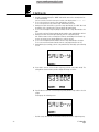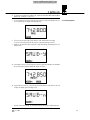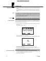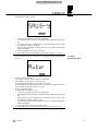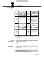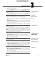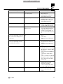
1
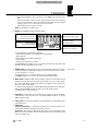
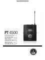
PT 4500
BEDIENUNGSANLEITUNG S. 2
. .
Bitte vor Inbetriebnahme des Gerätes lesen!
USER INSTRUCTIONS
. . . . . . . .
p. 20
Please read the manual before using the equipment!
MODE D’EMPLOI
. . . . . . . . . . . . . . . .
p. 38
Veuillez lire cette notice avant d’utiliser le système!
ISTRUZIONI PER L’USO
. . . . .
p. 56
Prima di utilizzare l’apparecchio, leggere il manuale!
MODO DE EMPLEO
. . . . . . . . . . . .
p. 74
¡Sirvase leer el manual antes de utilizar el equipo!
INSTRUÇÕES DE USO
. . . . . . . .
p. 92
Favor leia este manual antes de usar o equipamento!
Table of Contents
Page
1 Safety and Environment...........................................................................................................21
1.1 Safety.................................................................................................................................21
1.2 Envionment.........................................................................................................................21
FCC Statement .........................................................................................................................21
2 Description...............................................................................................................................22
2.1 Introduction.........................................................................................................................22
2.2 Packing List ........................................................................................................................22
2.3 Optional Accessories............................................................................................................22
2.4 Description .........................................................................................................................22
2.4.1 Controls .....................................................................................................................22
2.4.2 Microphones, Instrument Cable (optional)......................................................................24
3 Setting Up ................................................................................................................................25
3.1 Connecting a Microphone/Instrument....................................................................................25
3.2 Inserting Batteries................................................................................................................25
3.3 Operating Modes .................................................................................................................25
3.4 Powering Up........................................................................................................................26
3.4.1 Powering Up in SILENT Mode .......................................................................................26
3.4.2 Powering Up in LOCK Mode .........................................................................................26
3.5 Powering Down ...................................................................................................................27
3.6 Setting the Carrier Frequency................................................................................................27
3.6.1 Preset Menu...............................................................................................................27
3.6.2 Frequency Menu.........................................................................................................29
3.7 Multichannel Systems ..........................................................................................................30
3.8 Setting Input Gain ................................................................................................................30
3.8.1 Setting Gain Manually..................................................................................................30
3.8.2 Using Automatic Gain Mode .........................................................................................31
4 Operating Notes .......................................................................................................................32
4.1 Status Screens and Setup Menus..........................................................................................32
4.1.1 LOCK Mode................................................................................................................32
4.1.2 ACTIVE and SILENT Modes ..........................................................................................32
4.2 Selecting Modes..................................................................................................................32
4.3 Muting the Microphone ........................................................................................................33
4.3.1 Optional Remote Mute Switch ......................................................................................33
4.4 Replacing Batteries..............................................................................................................33
4.5 Microphone Technique .........................................................................................................33
4.5.1 C 417 L, CK 55 L Lavalier Microphones.........................................................................33
4.5.2 C 420 L, C 444 L Head-worn Microphones....................................................................33
4.6 Multichannel Systems ..........................................................................................................33
4.7 Battery Care........................................................................................................................33
5 Cleaning...................................................................................................................................34
6 Error Messages........................................................................................................................35
7 Specifications ..........................................................................................................................37
20
PT 4500
1 Safety and Environment
1. Do not expose the equipment to direct sunlight, excessive dust, moisture, rain, mechanical vibrations, or shock.
1. Be sure to dispose of used batteries as required by local waste disposal rules. Never
throw batteries into a fire (risk of explosion) or garbage bin.
2. When scrapping the equipment, remove the batteries, separate the case, circuit boards,
and cables, and dispose of all components in accordance with local waste disposal rules.
3. The packaging of the equipment is recyclable. Dispose of the packaging in an appropriate
container provided by the local waste collection/recycling entity and observe all local
legislation relating to waste disposal and recycling.
!
L
1.1 Safety
1.2 Environment
FCC Statement
This equipment has been tested and found to comply with the limits for a Class B digital device, pursuant to Part 74 of the
FCC Rules. These limits are designed to provide reasonable protection against harmful interference in a residential installation. This equipment generates, uses, and can radiate radio frequency energy and, if not installed and used in accordance
with the instructions, may cause harmful interference to radio communications. However, there is no guarantee that interference will not occur in a particular installation. If this equipment does cause harmful interference to radio or television reception, which can be determined by turning the equipment off and on, the user is encouraged to try to correct the interference
by one or more of the following measures:
•
•
•
•
Reorient or relocate the receiving antenna.
Increase the separation between the equipment and the receiver.
Connect the equipment into an outlet on a circuit different from that to which the receiver is connected.
Consult the dealer or an experienced radio/TV technician for help.
Shielded cables and I/O cords must be used for this equipment to comply with the relevant FCC regulations.
Changes or modifications not expressly approved in writing by AKG Acoustics may void the user’s authority to operate this
equipment.
PT 4500
21
2 Description
2.1 Introduction
Dear Customer:
Thank you for purchasing an AKG product. This Manual contains important instructions for
setting up and operating your equipment. Please take a few minutes to read the instructions below carefully before operating the equipment. Please keep the Manual for future reference. Have fun and impress your audience!
2.2 Packing List
1 PT 4500
bodypack transmitter
2 AA size 1.5 V
dry batteries
• Check that the package contains all the parts listed above. If anything is missing, please
contact your AKG dealer.
2.3 Optional Accessories
• For optional accessories, refer to the current AKG catalog or folder, or visit www.akg.com.
Your dealer will be glad to help.
2.4 Description
You can use the PT 4500 bodypack transmitter with both dynamic microphones and condenser microphones operating on a supply voltage of approx. 6 volts. You may also connect
an electric guitar, electric bass, or remote keyboard.
The PT 4500 operates in one subband up to 30 MHz wide within the 500 MHz to 862 MHz
UHF carrier frequency band. Within the subband, you can either set the carrier frequency directly in 25-kHz increments or select one of the Channels of the Preset Frequency Groups
of your transmitter.
The transmitter provides three operating modes:
In LOCK mode, the microphone output signal is transmitted to the receiver. All setup functions and controls except for the MUTE switch are electronically locked to prevent parameters from being readjusted unintentionally during a performance or lecture. The LCD screen
displays the "LOCK" label.
ACTIVE mode allows you to adjust and save the carrier frequency and input gain.
In SILENT mode, power to the transmitter is on, but no RF signal is transmitted. We recommend using only this mode for setting the carrier frequency. This is the only way to make
sure you won't "go on air" on a frequency that is not allocated or coordinated and risk "jamming" some other radio service or active radio mic.
The backlit LCD screen indicates all important parameters, the current battery capacity, and
the remaining time before the battery will be dead.
The transmitter can be powered from two standard AA size dry batteries or the optional
BP 4000 battery pack from AKG.
!
L
Important!
2.4.1 Controls
Refer to fig. 1.
22
• Never use standard rechargeable batteries! These may damage the transmitter
if the charging contacts are shorted and will provide no remaining battery life indication. AKG will accept no liability for any damage resulting from the use of
standard rechargeable batteries.
1 Status LED: This bicolor LED indicates the current operating status of the transmitter:
Green: The output signal of the microphone or instrument is fed to the transmitter, which
transmits the audio signal to the receiver.
Red: The Status LED is lit red
- if the audio signal is muted while the RF section remains active. This prevents unwanted noise from becoming audible in the signal chain;
PT 4500
2 Description
-
approximately 60 minutes before the batteries or BP 4000 battery pack wil be dead;
and
- while the transmitter recalls the carrier frequency from memory after you turned
power to the transmitter on. Unless you muted the audio signal, the status LED will
change to green as soon as the frequency has been recalled.
- while the display shows an error message.
Dark: The transmitter is in SILENT mode.
2 Display: The transmitter provides a five-line display:
Alphanumeric display of
the currently active value
or battery capacity in hours
Battery capacity
or audio level bar graph
Preset Name, Frequency Group,
Channel (Preset menu only)
Operating condition,
measurement unit
Parameter to be adjusted
The display indicates all transmitter parameters:
- Carrier frequency in MHz or as a Channel of a Frequency Group
- Audio input level
- Battery status and remaining operating time
- Error messages
- Setup menus: Frequency, Preset, Gain
The backlighting of the display comes on every time you actuate the setup switch and
will switch off after approximately 10 seconds.
3 ON/OFF button: A short push (approx. 0.6 seconds) will switch power to the transmitter ON and activate the display (2) and status LED (1). The transmitter will be ready to
operate after approx. 7 seconds.
A long push (approx. 2 seconds) will switch power to the transmitter OFF.
The ON/OFF button is recessed for protection from unintentional actuation.
Refer to fig. 1.
4 MUTE switch: Sliding the MUTE switch toward the outside of the transmitter (arrow)
will mute the audio signal. The status LED (1) will change to red. Since power and the
RF section remain ON, no unwanted noise will become audible from the sound system
when you mute the audio signal.
To switch the audio signal back on, slide the MUTE switch toward the inside of the transmitter (toward the ON/OFF switch). The status LED (1) will change to green.
The MUTE switch is active in all modes.
5 Audio input: 3-pin mini XLR connector with both mic and line level pins that automatically match the connector pinout of the recommended AKG microphones or optional
MKG L instrument cable.
6 Setup switch: Sets the various parameters of the transmitter. The setup switch has the
following functions:
• LOCK mode:
Turn left or right briefly to scroll between Frequency, Preset (only if a Preset has been
loaded), Gain, and Battery Capacity (shown in hours) screens.
Long push: toggles between LOCK and ACTIVE modes when the transmitter is ON.
When power to the transmitter is OFF, a long push switches the transmitter ON and
places it in SILENT mode.
PT 4500
23
2 Description
• ACTIVE and SILENT modes only:
Short push: calls up a parameter for adjustment or confirms a selected value.
Turn left briefly to select a menu item or decrease a parameter value.
Turn right briefly to select a menu item or increase a parameter value.
Turn left or right and hold to scroll through available values.
7 Charging contacts: The recessed charging contacts allow you to recharge the optional
AKG BP 4000 battery pack on the optional CU 4000 charger without having to remove
the battery pack from the transmitter.
8 REMOTE MUTE jack: This jack allows you to connect the optional Remote Mute switch.
9 Antenna: Permanently connected, flexible antenna.
10 Battery conmpartment door
11 Frequency sticker: Sticker attached to the transmitter rear panel, indicating the available carrier frequency range and approval data.
12 Battery compartment accepting the two supplied 1.5 V AA size batteries or the optional
BP 4000 battery pack.
13 Belt Clip for fixing the transmitter to your belt.
2.4.2 Microphones,
Instrument Cable
(optional)
Refer to fig. 2.
You can connect the following microphones to the audio input of the PT 4500:
• CK 55 L, C 417 L, C 520 L, C 555 L
• C 516 ML, C 518 ML, C 519 ML
• The MKG L instrument cable from AKG lets you connect an electric guitar, electric bass,
or remote keyboard to the bodypack transmitter. For further details, refer to the respective AKG brochures or visit www.akg.com.
24
PT 4500
3 Setting Up
• Prior to setting up your WMS 4500, check that the transmitter and receiver are
tuned to the same frequency, referring to section 3.6 and the receiver manual.
• We recommend setting all channels to the same Preset and the same Group.
In the following sections, flashing characters are identified by angle symbols ">" and "<".
All values shown are examples of available settings.
Short push on the setup switch.
!
L
Important!
Note:
Symbols
Long push on the setup switch.
Turn the setup switch briefly to the left.
Turn the setup switch briefly to the right.
Turn the setup switch briefly to the left or
right.
The PT 4500 bodypack transmitter has been designed primarily for use with "L" type
MicroMic Series microphones from AKG (see section 2.4.2). If you wish to connect other
microphones from AKG or other manufacturers to the PT 4500, please note that you may
have to rewire the existing connector of your microphone or replace it with a 3-pin mini XLR
connector.
3.1 Connecting
a Microphone/Instrument
Refer to fig. 2.
Audio input pinout:
Pin 1: shield
Pin 2: audio (inphase)
Pin 3: audio
A positive supply voltage of 6 volts for condenser microphones is available on pin 2.
Please note that AKG cannot guarantee that the PT 4500 bodypack transmitter will
work perfectly with products from other manufacturers and any damage that may result from such use is not covered by the AKG warranty scheme.
!
L
Important:
• Plug the mini XLR connector (1) on the cable of your microphone or on the MKG L instrument cable (2) into the audio input connector (3) on the bodypack transmitter.
1. Open the battery compartment door (1).
2. Insert the two supplied batteries into the battery compartment, aligning the batteries
with the polarity symbols inside the battery compartment.
If you insert the batteries the wrong way, the transmitter will not be powered.
3. Close the battery compartment door (1).
3.2 Inserting Batteries
Refer to fig. 3.
• Alternatively to the supplied dry batteries, you may use the optional BP 4000 battery
pack from AKG. The BP 4000 fits into the battery compartment in the correct orientation only, so you cannot insert it the wrong way.
Note:
• Never use standard rechargeable batteries! These may damage the transmitter
if the charging contacts are shorted and will provide no remaining battery life indication. AKG will accept no liability for any damage resulting from the use of
standard rechargeable batteries.
1. LOCK mode: The transmitter transmits the microphone output signal to the receiver. All
PT 4500
!
L
Important!
3.3 Operating Modes
25
3 Setting Up
adjustment functions are electronically locked to prevent parameters from being readjusted unintentionally during a performance or lecture.
2. ACTIVE mode: The transmitter transmits the microphone output signal to the receiver.
All controls are active. You can check all transmitter parameters and set the carrier frequency (refer to section 3.6) and input gain (refer to section 3.8).
3. SILENT mode: Power to the transmitter is ON, but no RF signal is transmitted. The
status LED remains dark. You can check all transmitter parameters and set the carrier
frequency (refer to section 3.6) and input gain (refer to section 3.8).
!
L
Important!
• We recommend setting the carrier frequency in SILENT mode only. This is the
only way to make sure you won't "go on air" on a frequency that is not allocated
or coordinated and risk "jamming" some other radio service or active radio mic.
3.4 Powering Up
Depending on the way you switch power to the transmitter ON, the transmitter will be in either LOCK mode or SILENT mode on powering up.
!
L
Important!
3.4.1 Powering Up
in SILENT Mode
Refer to fig. 1.
• If you are not sure as to what carrier frequency the transmitter is tuned to, switch
the transmitter to SILENT mode (refer to section 3.4.1 below) and check that the
current carrier frequency is legal and identical to the frequency selected on the
receiver.
1. Push and hold the setup switch (6) until the backlighting of the display (2) comes on.
The display (2) will first show the firmware version and then the currently selected carrier frequency in MHz.
As the backlighting goes out, the display changes as follows:
The transmitter is now in SILENT mode.
2. If the carrier frequency is not an allocated or coordinated one and/or different from the
receiver frequency, set the transmitter to a suitable, legal frequency referring to section
3.6.
3.4.2 Powering Up
in LOCK Mode
Refer to fig. 1.
26
1. Press the ON/OFF button (3) for approx. 0.6 seconds.
2. As soon as the below screen appears on the display (2), the transmitter is in LOCK mode.
PT 4500
3 Setting Up
The "LOCK" label indicates that all controls except for the MUTE switch are electronically locked to prevent misadjustment.
• If the microphone is muted, the "MUTE" label appears on the display and the status LED
is lit red. If the microphone is active, "MUTE" will not appear and the status LED will be
lit green.
Note:
• Push and hold the ON/OFF button (3) until the message "oFF" appears on the display
(2).
The display goes dark and power to the transmitter is OFF.
3.5 Powering Down
(all modes)
Refer to fig. 1.
• If you are not sure what carrier frequency the transmitter is tuned to, place the
transmitter into SILENT mode following steps 1 and 2 below. In SILENT mode,
you can check and adjust the carrier frequency and input gain without transmitting a radio signal.
3.6 Setting the Carrier
Frequency
!
L
Important!
1. If the transmitter is ON, switch it OFF.
2. Push and hold the setup switch until the display backlighting comes on.
The display will first show the battery capacityin hours and as a bargraph and then the
currently selected carrier frequency in MHz.
As the backlighting goes out, the display changes as follows:
The transmitter is now in SILENT mode and the display shows the Preset menu.
3. You can either select one of the Preset Channels from the Preset menu (section 3.6.1)
or set the carrier frequency in 25-kHz increments in the Frequency menu (section 3.6.2).
The spacing between Preset frequencies prevents any mutual interference.
A Preset comprises one or more Groups of carrier frequencies. Group numbers are shown
under the "GRP" label. Carrier frequencies are also called "Channels" whose numbers are
indicated below the "CH" label. The spacing between these frequencies is wide enough to
prevent any mutual interference (intermodulation). Presets make it much easier to design a
multichannel system. They save time because you do not need to calculate your own carrier frequencies and help you avoid intermodulation problems.
Each Preset has a one or two-character "NAME" relating to the country where the respective carrier frequencies are allocated (e.g., "SD" for countries with no regulations, "US" for
the USA, or "UK" for Britain, etc.). The Preset names are sorted alphabetically.
When designing a multichannel system, make sure to use Channels within the same Group
only. Using Channels of different Presets and/or Groups simultaneously may cause intermodulation.
3.6.1 Preset Menu
• Some Presets may be approved in more than one country. To check which Frequency
Group(s) is (are) approved in your country, visit www.akgfrequency.at or contact your
local regulation authority.
Note:
PT 4500
27
3 Setting Up
1. Push the setup switch briefly. The "NAME" label and the name of the currently active Preset will start flashing.
If no Preset has been stored in memory, the 2nd line of the display shows "-- -- --".
2. To select the next Preset, turn the setup switch briefly to the right.
To select the previous Preset, turn the setup switch briefly to the left.
3. Having selected the desired Preset, push the setup switch briefly. The "GRP" label and
the number of the currently active Frequency Group will start flashing.
4. To select the next higher Frequency Group number, turn the setup switch briefly to the
right.
To select the next lower Frequency Group number, turn the setup switch briefly to the left.
5. Having selected the desired Frequency Group, push the setup switch briefly.
"CH" and the number of the currently active Channel start flashing. Each Channel represents one factory-preset, intermodulation-free carrier frequency.
6. To select the next higher Channel number, turn the setup switch briefly to the right.
To select the next lower Channel number, turn the setup switch briefly to the left.
7. Having finished your settings, push the setup switch briefly. This brings up the following
screen:
8a If you want to save the selected carrier frequency, push the setup switch briefly. The
setting will be saved in memory and the display will change as follows:
8b If you'd rather not save the selected frequency, briefly turn the setup switch to the left
or right.
This brings up the following screen:
28
Push the setup switch briefly. The transmitter will stay tuned to the original frequency.
PT 4500
3 Setting Up
9. To switch the transmitter into LOCK mode, switch the transmitter OFF and back ON in
LOCK mode, referring to section 3.4.2.
1. To move from the Preset to the Frequency menu, turn the setup switch briefly to the left.
Press Setup briefly. The display will change like this:
3.6.2 Frequency Menu
2. To increase the frequency by 25 kHz, turn the setup switch briefly to the right.
To decrease the frequency by 25 kHz, turn the setup switch briefly to the left.
3. Having set the desired frequency, push the setup switch briefly. This brings up the following screen:
4a If you want to save the selected frequency, push the setup switch briefly. Your setting will
be saved in memory and the display will change as follows:
4b If you'd rather not save the selected frequency, briefly turn the setup switch to the left
or right. This brings up the following screen:
-
Push the setup switch briefly. The transmitter will stay tuned to the original frequency.
PT 4500
29
3 Setting Up
3.7 Multichannel Systems
1. Be sure to assign a separate carrier frequency to each wireless channel (transmitter and
receiver).
2. To find intermodulation-free carrier frequencies quickly and easily, we recommend selecting all required carrier frequencies from the same Frequency Group within the same
Preset.
Note:
• If reception on the selected carrier frequency is poor, use Automatic Frequenc y Selection on the receiver to find the next clean Channel within the selected Frequency Group.
Should you find no clean Channel, use Automatic Frequenc y Selection on the receiver
to select a different Frequency Group within the same Preset and selecet a new frequency for each transmiter and receiver.
!
L
Important!
• Do not operate two or more wireless channels on the same frequency at the same
time and location. This would cause unwanted noise due to radio interference.
3.8 Setting Input Gain
You can set the transmitter input gain either in SILENT mode or in ACTIVE mode. We recommend setting the input gain in ACTIVE mode because you can switch to LOCK mode directly, without having to power down first.
1. To move from LOCK mode to ACTIVE mode, push and hold the setup switch for approx.
two seconds.
The display will change as follows:
2. Turn the setup switch briefly to the right once.
The display will show the current input gain in dB and the "GAIN" label will be flashing.
3. Push the setup switch briefly.
The currently selected input gain value in dB will be flashing on the display:
4. Set the audio section input gain either manually (continue with section 3.8.1) or in Automatic Gain mode (continue with section 3.8.2).
3.8.1 Setting Gain Manually
30
1. To increase the gain value by 1 dB, turn the setup switch briefly to the right.
To decrease the gain value by 1 dB, turn the setup switch briefly to the left. The readout
"00" will be followed by "Auto" (refer to section 3.8.2).
2. Push the setup switch briefly.
PT 4500
3 Setting Up
The display will change as follows:
• To save the new setting, push the setup switch briefly.
The display will show your new gain setting in dB and the "GAIN" label will be flashing.
• If you'd rather not save your setting, turn the setup switch briefly to the left or right.
The display will change to "SAVE-N".
- Push the setup switch briefly. The display will revert to the original setting, with the
"GAIN" label flashing.
3. To set input gain again, repeat steps 1 and 2 above.
4. To return to LOCK mode, push and hold the setup switch for approx. 1.5 seconds.
1. From the Gain menu, turn the setup switch to the left and hold until the display changes
as follows:
3.8.2 Using
Automatic Gain Mode
2. Push the setup switch briefly.
The message ”>tESt<” will start flashing on the display.
3. Talk or sing into the microphone as loud as you can.
The transmitter will automatically set the optimum input gain.
The display indicates the audio level by short lines. The peak level is indicated by a heavier line that will remain fixed for approx. 2 seconds.
4. Push the setup switch briefly.
The display will show “SAVE >-Y<”.
• To save the new setting, push the setup switch briefly.
The display will show your new gain setting in dB and the "GAIN" label will be flashing.
• If you'd rather not save your setting, turn the setup switch briefly to the left or right.
The display will change to "SAVE >-N<".
- Push the setup switch briefly. The display will revert to your original setting, with the
"GAIN" label flashing.
5. To set input gain again, repeat steps 1 through 4 above.
6. To return to LOCK mode, push and hold the setup switch for approx. two seconds.
PT 4500
31
4 Operating Notes
4.1 Status Screens and
Setup Menus
4.1.1 LOCK Mode
In LOCK mode, four status screens are available.
1
Frequency screen: Carrier
frequency in MHz, battery
capacity bars. The "MUTE"
label appears if the microphone is muted.
2
Gain screen: Input gain in
dB.
3
4
Preset screen (comes up
only if at least one Preset
has been saved): Carrier
frequency as Subchannel
number within a Frequency
Group, battery capacity
bars. If the microphone is
ON, the "MUTE" label is off.
Battery screen: Battery
capacity in hours and as
bar graph. If the microphone is ON, the "MUTE"
label is off.
1. To scroll through the status screens in the order shown above, turn the setup switch
briefly to the right.
2. To step through the above screens in reverse order, turn the setup switch briefly to the
left.
32
4.1.2 ACTIVE
and SILENT Modes
• To call up the setup menus described in sections 3.4 through 3.8 in the order shown
below, turn the setup switch briefly to the left:
- Preset menu
- Frequency menu
- Battery screen
- Gain menu
4.2 Selecting Modes
• To toggle between LOCK mode and ACTIVE mode, push and hold the setup switch for
approx. two seconds.
In LOCK mode, the "LOCK" label will be shown on the display.
Note:
• The transmitter is on the air in ACTIVE mode, too. Remember, though, that settings may
change if you inadvertently actuate the setup switch.
The transmitter will revert to LOCK mode after about 15 minutes.
PT 4500
4 Operating Notes
• To toggle between LOCK or ACTIVE mode and SILENT mode:
1. Switch power to the transmitter OFF.
2. Hold down the ON/OFF switch for approx. 0.6 seconds to enter LOCK mode OR hold
down the setup switch for approx. two seconds to enter SILENT mode.
1. To mute the microphone, slide the MUTE switch (4) to the "MUTE" position. The status
LED (1) will change to red.
2. To switch the microphone back ON, slide the MUTE switch (4) to the "ON" position. The
status LED (1) will change to green.
4.3 Muting the Microphone
Refer to fig. 1.
The optional Remote Mute Switch allows you to mute the transmitter if it is mounted in a position where it is difficult or impossible to use the "on-board" MUTE switch.
4.3.1 Optional
Remote Mute Switch
1. Plug the cable (1) on the Remote Mute Switch into the REMOTE MUTE jack (2) on the
transmitter.
2. Put the Remote Mute Switch in a jacket or shirt pocket or use the belt clip to clamp the
Remote Mute Switch on the belt.
3. To mute the microphone, press the button on the Remote Mute Switch. The button will
lock and the status LED will change to red.
4. To switch the microphone back on, press the button again. The status LED will change
to green.
Refer to fig. 4.
In LOCK mode, the display constantly indicates the current battery capacity as a string of bars
below the frequency readout.
If the "BATT" label starts flashing, a dash appears instead of the bars, and the status LED
changes to red, replace the batteries or charge the AKG BP 4000 battery pack as soon as
possible.
You can check the remaining battery capacity at any time by turning the setup switch briefly
to the left or right one to three times (depending on the currently active screen). The battery
capacity will be displayed in hours and as a string of bars.
4.4 Replacing Batteries
1. Fix the microphone to the H 40/1 lavalier clip or H 41/1 tie pin referring to the microphone’s instruction manual.
2. Clamp the microphone on your clothing as close as possible to your mouth.
Remember that gain-before-feedback will be the higher the smaller the distance between the microphone and the mouth!
3. Make sure to aim the microphone at your mouth.
4.5 Microphone Technique
4.5.1 C 417 L, CK 55 L
Lavalier Microphones
• Refer to the user’s manual of the respective microphone for instructions on how to use
head-worn microphones.
4.5.2 4.2 C 520 L, C 555 L
Head-worn Microphones
• If reception on the selected carrier frequency is poor, use Automatic Frequency Selection (“FREQ -> CHANNEL -> AUTO”) on the receiver to find the nearest clean Channel
within the selected Frequency Group.
• Should you find no clean Channel, useAutomatic Frequency Selection (“FREQ -> GROUP
-> AUTO”) on the receiver to select a different Frequency Group within the same Preset and selecet a new frequency for each transmiter and receiver.
4.6 Multichannel Systems
1. If you know you won’t be using the transmitter fo more than a week, remove the batteries or BP 4000 battery pack from the transmitter.
2. Make it a habit to charge the BP 4000 battery pack fully every time you used the transmitter for at least one or two hours. This is a good way to prevent the battery pack from
dying in the middle of the next gig.
3. Always charge the BP 4000 battery pack fully before storing it outside the transmitter.
This will maintain the battery pack’s capacity at a higher level for a longer time.
4.7 Battery Care
PT 4500
33
5 Cleaning
• To clean the transmitter surfaces, use a soft cloth moistened with water.
34
PT 4500
6 Error Messages
Error Messages
Problem
Remedy
Err.>rF<
PLL error. (Receiver unable to lock on
to selected frequency.)
Err.>SYS<
Frequency settings cannot be changed. 1. Switch power to transmitter OFF and
back ON after about 10 seconds.
2. If problem persists, contact your
nearest AKG Service Center.
Err.>USr<
Last setting cannot be loaded.
Err.>FrE<
Frequencies cannot be selected from
Frequency screen.
Err.>PrE<
All Presets defective; no Preset selec(comes up on powering up or when try- table.
ing to select a Preset and appears on
receiver, too.)
Err.>PrE<
(comes up on powering up only and
does not appear on receiver.)
Err.>rPt<
1. Press setup switch briefly and set
different frequency.
2. If problem persists, contact your
nearest AKG Service Center.
1. Set frequency again.
2. If problem occurs frequently, contact
your nearest AKG Service Center.
1. Continue with previous setting.
2. Press setup switch briefly and set
frequency from Preset screen.
3. If problem occurs frequently, contact your nearest AKG Service Center.
1. Use frequency screen to set frequency
(section 3.6.2).
2. Contact your nearest AKG Service
Center.
One or more Presets defective.
1. You can select Presets, but note
that defective Presets will not be
available.
2. Contact your nearest AKG Service
Center.
No remaining battery life data available. 1. Check batteries: replace standard
rechargeable batteries immediately
with dry batteries or AKG BP 4000
battery pack.
2. Remove and reinsert BP 4000 battery pack.
3. If error persists, charge battery
pack.
4. If error occurs with several different
battery packs or types of dry batteries, contact your nearest AKG
Service Center.
Err.>AF<
No signal at audio input.
1.
2.
3.
4.
Rec.>Acc<
BP 4000 battery pack needs recovery.
• Run recovery cycle. Refer to User
Manual of optional CU 4000
charger.
PT 4500
Check microphone element.
Mount microphone element.
Briefly push setup switch.
If error occurs frequently, contact
your nearest AKG Service Center.
35
6 Error Messages
Error Message
Err.>JoG<
Problem
Internal setup switch error.
Remedy
1. (Setup switch responds in spite of
error message:) Switch power to
transmitter off, wait for 10 seconds, and switch power back on.
2. (Setup switch fails to respond:) Remove and reinsert batteries/BP
4000 battery pack, and switch
power to transmitter on.
3. If error persists, contact your nearest AKG Service Center.
• The above error messages may appear on the display upon powering up or during operation:
• To delete an error message, push the setup switch.
• For more hints on troubleshooting, refer to the SR 4000 receiver manual.
36
PT 4500
7 Specifications
Carrier frequency ranges:
Carrier frequencies:
Modulation:
Rated deviation:
Audio bandwidth:
T.H.D. at 1 kHz:
S/N Ratio (A-weighted)
RF output:
Audio input:
Input level:
Current consumption:
Power requirement:
Battery life:
Size:
Net weight:
500 - 530, 570 - 600, 650 – 680, 680 – 710, 720 – 750,
760 – 790, 790 – 820, 835 - 862 MHz
up to 1,200
FM
±20 kHz
35 Hz to 20 kHz
<0.3% at rated deviation
118 dB(A) typical
50 mW max. ERP
3-pin mini XLR connector
140 dB-SPL @ nominal deviation
<135 mA
2 AA size 1.5 V batteries or
BP 4000 rechargeable battery pack
dry batteries: 15 hours typical, BP 4000: 12 hrs. typical
70 x 90 x 25 mm (2.8 x 3.5 x 1 in.)
320 g (11.3 oz.) without batteries
This product conforms to the standards listed in the Declaration of Conformity. To order a free copy of the Declaration of
Conformity, visit http://www.akg.com or contact [email protected].
PT 4500
37
Notizen • Notes • Notes • Note • Notas • Notas
110
PT 4500
Notizen • Notes • Notes • Note • Notas • Notas
PT 4500
111
Mikrofone · Kopfhörer · Drahtlosmikrofone · Drahtloskopfhörer · Kopfsprechgarnituren · Akustische Komponenten
Microphones · Headphones · Wireless Microphones · Wireless Headphones · Headsets · Electroacoustical Components
Microphones · Casques HiFi · Microphones sans fil · Casques sans fil · Micros-casques · Composants acoustiques
Microfoni · Cuffie HiFi · Microfoni senza filo · Cuffie senza filo · Cuffie-microfono · Componenti acustici
Micrófonos · Auriculares · Micrófonos inalámbricos · Auriculares inalámbricos · Auriculares con micrófono · Componentes acústicos
Microfones · Fones de ouvido · Microfones s/fios · Fones de ouvido s/fios · Microfones de cabeça · Componentes acústicos
AKG Acoustics GmbH
Lemböckgasse 21–25, A-1230 Vienna/AUSTRIA, phone: (+43-1) 86654-0*
e-mail: [email protected]
For other products and distributors worldwide visit www.akg.com
Technische Änderungen vorbehalten. Specifications subject to change without notice. Ces caractéristiques sont susceptibles de modifications.
Ci riserviamo il diritto di effettuare modifiche tecniche. Nos reservamos el derecho de introducir modificaciones técnicas. Especificações sujeitas
a mudanças sem aviso prévio.
Printed in China (P.R.C.)
02/08/9100 U 12760
Fig. 1
PT 4500
�
�
�
�
�
12
�
�
13
10
11
�
10
Fig. 2
1
�
�
�
2
�
�
�
13
�
13
�
Fig. 4
1
2
�
�
�
Fig. 3
1
1a
�
2
�
2 x 1.5V
2a
�
�
2b
3
BP 4000
�
3a
�