1
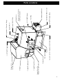
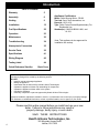
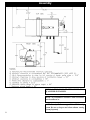
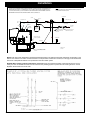
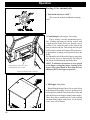
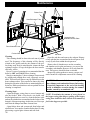
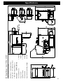
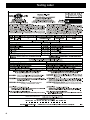
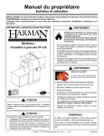
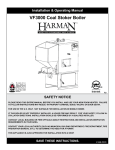
Installation & Operating Manual
The Harman PB 105 Pellet Boiler
“Ce manuel est disponible en Français sur demande”
R10
SAFETY NOTICE
Warning! Risk of fire or exploision!
• Improper installation, operation or maintenance of this boiler can cause injury or
death.
• Follow all instructions contained in this manual
BEfore installation and use of this boiler:
• Please Read and understand this entire manual.
Consult your local authorities having jurisdiction.
• Contact your municipal building department, Fire department, or other local
authorities before installing this boiler.
• Local building regulations may require special permits, restrictions and inspection
requirements.
save these instructions
Manual #3-90-07205
Access Cover To Secondary Ash Chamber
Ash Door
Firebox Door
Viewing Glass
Access Cover To
Hopper / Swing Plate Knob
Control Board Cover
Control Board
Hopper
Hopper Lid
Latches
1-1/4” FMPT Supply
1/2” FMPT Boiler Drain
Combustion Blower Cover
Combustion Blower
Vent Pipe
1-1/4” FMPT Return
(Removed w/ Domestic
Hot Water Option)
Blank Cover
Pressure Relief Valve
Aquastat Well
Temperature / Pressure Gauge
Parts Locations
3
Introduction
Table Of Contents
Warranty 5
Assembly
6
Venting
9
Installation
12
Fuel Specifications
22
Operation
23
Maintenance 30
Troubleshooting
34
Atmospheric Conversion
35
Service Parts
36
Specifications
41
Wiring Diagram
42
Testing Label
44
Appliance Certification.
Model: Pellet Burning Boiler - PB105
Test Lab: Omni-Test Laboratories, Inc.
Report #: 135-S-16-6
Type: Pellet Fueled Central/Supplementary For
Residential Use
Standard(s): CAN/CSA B366.1-M91, and UL 391
Note: This appliance is also approved for
installation into a shop.
Quick Reference Start-UpBack Cover
WARNING! RISK OF FIRE! Hearth & Home Technologies disclaims any responsibility for, and the warranty
and agency listing will be voided by the following actions:
DO NOT:
• Install or operate a damaged appliance
• Modify the appliance
• Install other than as instructed by Hearth & Home Technologies
• Operate the appliance without fully assembling all components
• Operate the appliance without water in the system
• Overfire the appliance
• Install any component or part not approved by Hearth & Home Technologies
Improper installation, adjustment, alteration, service, or maintenance can cause injury or property damage.
For assistance or additional information, consult a qualified installer, service agency or your dealer.
Please read this entire manual before you install and use your new
boiler. Failure to follow instructions may result in
property damage, bodily injury, or even death.
SAVE THESE INSTRUCTIONS
Hearth & Home Technologies, Inc.
4
352 Mountain House Road
Halifax, PA 17032
Warranty
HARMAN™ CENTRAL HEATING PRODUCTS LIMITED WARRANTY
Hearth & Home Technologies Inc., on behalf of its Harman™ brand (”HHT”), extends the following warranty for all
Harman™ furnace and boiler products (“Products”) that are purchased from an HHT authorized dealer.
Warranty Coverage: Subject to the conditions, exclusions and limitations set forth below, HHT warrants to the original owner of the Products, and to any transferee taking ownership of the Products at the site of original installation
within two years following the date of original purchase, that the Products will operate free from defects in material
and workmanship under normal conditions and use, as described in the operating instructions furnished with the Product, during the warranty period described below. HHT will, at its option, repair or replace any Product covered by this
warranty that is determined to be defective in material or workmanship.
Warranty Period: The warranty period runs for six years, except for mechanical and electrical components, which
are warranted for three years. The warranty period begins on the earlier of: (i) the date of invoice for the Product; (ii)
in the case of new home construction, the date of first occupancy of the residence or six months after the date of sale
of the Product by an HHT authorized dealer, whichever occurs first; or (iii) the date 24 months following the date of
Product shipment from HHT, regardless of the invoice or occupancy date.
Warranty Conditions: This warranty applies only to Products: (i) installed, operated, and maintained as recommended
in the Product user’s manual; (ii) purchased through an HHT authorized dealer; (iii) while remaining at the site of
original installation; and (iv) that have not been altered after leaving the factory.
How to File a Claim: Claims must be made within the warranty period to the dealer who sold the Product. If that
dealer cannot provide the warranty service, contact the nearest HHT authorized dealer. Additional service fees may
apply if you are seeking warranty service from a dealer other than the dealer from whom you originally purchased the
Product. Travel and shipping charges for parts are not covered by this warranty.
Warranty Exclusions: This warranty does not cover the following: (1) consumable and normal wear items, including, without limitation, flame guides, grates, coal bars, afterburner hoods, fire brick, gaskets, paint, glass discoloration,
burnpot housing weldments, burnpot grate weldments (pellet or corn), burnpot front plates (pellet or corn), burnpot
front plate locks, corn auger extensions, ceramic inserts, and ceramic insert plates; (2) noise caused by minor expansion, contraction or movement of parts; (3) damage resulting from: (i) failure to install, operate or maintain the
Product according to the installation and operating instructions and listing agent identification label furnished with the
Product; (ii) failure to install the Product according to local building codes; (iii) shipping or improper handling; (iv)
abuse, misuse, continued operation with damaged, corroded or failed components, accident, or incorrectly performed
repairs; (v) environmental conditions, inadequate ventilation, negative pressure or drafting caused by tightly sealed
construction, insufficient make-up air supply, or handling devices such as exhaust fans or forced air furnaces or other
such causes; (vi) use of fuels other than those specified in the operating instructions; (vii) installation or use of components or accessories not supplied with the Product or authorized and approved in writing by HHT; (viii) modification of the product not expressly authorized and approved by HHT in writing; or (ix) interruptions or fluctuations of
electrical power supply to the Product; (4) non-HHT components or accessories used in conjunction with the Product;
(5) the Products’ capability to heat a desired space; information is provided to assist the consumer and the dealer in
selecting the proper Product for the application; consideration must be given to Product location and configuration,
environmental conditions, insulation and air tightness of the structure; or (6) additional or unusual utility bills incurred
due to any malfunction or defect in Products.
Limitations of Liability: Repair or replacement in accordance with the provisions of this warranty will be the owner’s
exclusive remedy for and will constitute HHT’s sole obligation under this warranty, under any other warranty (express
or implied), or in contract, tort or otherwise. No employee, agent, dealer, or other person is authorized to give any
warranty on behalf of HHT. TO THE EXTENT ALLOWED BY LAW, HHT MAKES NO OTHER WARRANTY, EXPRESS OR IMPLIED, INCLUDING ANY WARRANTY OF MERCHANTABILITY OR FITNESS FOR A PARTICULAR PURPOSE. HHT WILL NOT BE LIABLE FOR ANY CONSEQUENTIAL OR INCIDENTAL DAMAGES
ARISING OUT OF DEFECTS IN OR USE OF THE PRODUCTS. Some states do not allow exclusions or limitation
of incidental or consequential damages, so these limitations may not apply to you. This warranty gives you specific
rights; you also may have other rights, which vary from state to state. The duration of any implied warranty is limited
to the duration of the warranty period specified herein.
5
Assembly
Boiler Kit Materials: (Refer to page 3)
List of items contained within the boiler kit shipped with
the unit.
1 - Control board cover
1 - Access cover (Hopper Swing Plate Knob)
5 - Spring Handles
1 - 1/2” Boiler Drain
1 - 3/4” Safety Relief Valve
1 - 1/2” Aquastat Well
1 - 1/2” Dual Temperature/Pressure Gauge
1 - 100ft. Sensor Cable (Outdoor Air Sensor)
1 - Outdoor Air Sensor
1 - Flue Tunnel Weldment
1 - Combustion Blower Assembly
1 - Heat Shield (Comb. Blower)
2 - UY Connectors
2 - Terminals 1/4 Female
1 - #8 X 1/2” TEK
3 - 1/4-20 X 5/8” Wing Screw
4 - 1/4” Lock Washer
4 - 1/4-20 Nuts
Installation of the Flue Tunnel Weldment,
Combustion Blower and Wiring, ESP and Heat
Shield:
Step 1: First install the flue tunnel weldment by
aligning the (4) studs with the (4) holes in the ash
chamber base. Fasten the (4) nuts and lock washers
provided, to the studs by removing the access cover on
the secondary ash chamber.
Step 2: Place the combustion motor onto the flue tunnel
weldment and tighten the (3) wing screws provided.
Step 3: Insert the Exhaust Sensing Probe (ESP) into the
1/8” hole provided on the flue pipe stub. Fasten with
the (1) #8x1/2” TEK screw also provided. ESP will be
taped to the sheet metal jacket for shipping purposes.
Step 4: Connect the flex conduit 90 degree elbow(Not
Shown) to the heat shield in the hole provided. Then
connect the (3) wires from the combustion blower with
the (3) wires in the flex conduit by using the push-on
connectors and matching the wire colors as follows:
Red to Black, White to White and Green to Green.
Step 5: Place Heat Shield over combustion blower and
align the swell latches with the holes in the sheet metal
and tighten.
Flue Tunnel Weldment
ESP
Combustion Blower
Heat Shield
NOTE: Refer to Fig’s 22, 23, and 24 located on page 33 of this manual.
6
Assembly
42" CANADA
42" CANADA
18" CAN
16" USA
40" USA
40" USA
Refer to the illustration on page 3 to identify the compoMINIMUM NON-COMBUSTIBLE FLOOR PROTECTION AREA
nents listed below:
1. Install the control board cover as well as the access cover
located on the feeder cover.
2. Install the spring handles provided with the unit on the
NON-COMBUSTIBLE
ash door, firebox door and the heat exchanger cleanout rod
FLOOR PROTECTOR
handles. (Fasten handles by turning them counterclockwise
and pushing inward simultaneously).
3. Install 1/2” MPT boiler drain in the fitting as shown.
Note: Use pipe thread sealant or teflon tape on ALL
threads before connections are made.
4. Install 3/4” MPT pressure relief valve as shown.
5. Install the 1/2” MPT aquastat well in fitting as shown,
55" USA & CAN
then place aquastat in the well and fasten with a zip tie. The
aquastat sensor is located under the top sheet metal jacket.
6. Install the 1/2” MPT temperature/pressure gauge in
fitting as shown.
7. Locate and install outside air temperature sensor. Location of this sensor should be on the north side of the home or
building and out of direct sunlight. Use the cable supplied
with the boiler to attach the sensor to the terminals located
on the hopper. (Place at the back side just above and to the
right of the main power connection box) The wires can be
connected to the sensor with the connectors supplied. Wire
nut or butt splice connectors could also be used. The connections at the boiler can be done with the two 1/4” female
55" USA & CAN
push on connectors supplied.
8. Fasten the conduit to the ash base with the clamps
Floor Protection:
provided.
The striped area indicates the minimum required floor protection area if the boiler is going to be placed on a combustible
floor. It requires 40” X 55”(US) or 42” X 55”(CAN) of non
combustible floor protection as shown. 16”(US) or 18”(CAN)
Design:
The first thing that needs to be done is deciding where and of the floor protection must be in front of the firebox door
as shown. Floor protection must be a minimum of 26 gauge
how the boiler will be installed.
Things that need to be taken into consideration are the sheet metal. Floor protection must also be provided under any
intended use of the boiler for example, is the boiler going to horizontal run of vent pipe equal to the outside diameter of the
be used as your primary heating system or is it going to be venting plus 2” to each side.
used as a secondary or backup heating system. If it is to be Example: 4” type “L” or “PL” vent pipe has an outside diamused in conjunction with an existing oil or gas boiler system eter of 4-1/2” + 2” on each side equals a protected floor area
will it be piped in parallel or in series? The answers to these of 8-1/2” wide underneath the horizontal run.
and other questions can be determined by talking to your
certified dealer or a qualified HVAC or plumbing contractor. This will ensure that the boiler is installed and piped to
accommodate your needs and expectations.
Consideration must be given to the venting as well as
electrical and clearance requirements. (Clearances must be
maintained to combustibles and also for service)
Make sure fans are not used in the fuel storage area, unless
they are installed so as not to create a negative pressure in the
room where the solid fuel burning appliance is located.
7
Assembly
INSTALLATION IS TO BE PERFORMED BY A
QUALIFIED INSTALLER.
NOTE: All installation clearances and restrictions
must be adhered to.
NOTE:Use only 4” diameter type “L” or “PL” venting
system. Be sure to inspect and clean exhaust venting
system frequently.
8
Venting
Requirements for Terminating the Venting
WARNING: Venting terminals must not be recessed into
a wall or siding.
NOTE: Only PL vent pipe wall pass-throughs and fire
stops should be used when venting through combustible
materials.
NOTE: Always take into consideration the effect the
prevailing wind direction or other wind currents will
cause with flyash and /or smoke when placing the termination.
In addition, the following must be observed:
A. The clearance above grade must be a minimum of
18”.1
B. The clearance to a window or door that may be
opened must be a minimum of 48” to the side, 48”
below the window/door, and 12” above the window/
door.1
C. A 12” clearance to a permanently closed window is
recommended to prevent condensation on the window.
D. The vertical clearance to a ventilated soffit located
above the terminal within a horizontal distance of 2 feet
(60 cm) from the center-line of the terminal must be a
minimum of 18”.
E. The clearance to an unventilated soffit must be a
minimum of 12”.
F. The clearance to an outside corner is 11” from center
of pipe.
G. The clearance to an inside corner is 12”.
H. A vent must not be installed within 3 feet (90 cm)
= Vent terminal
= Air supply inlet
above a gas meter/regulator assembly when measured
from the horizontal center-line of the regulator.1
I. The clearance to service regulator vent outlet must be
a minimum of 6 feet.1
J. The clearance to a non-mechanical air supply inlet
to the building or the combustion air inlet to any other
appliance must be a minimum of 48”.1
K. The clearance to a mechanical air supply inlet must
be a minimum of 10 feet.1
L. The clearance above a paved sidewalk or a paved
driveway located on public property must be a minimum
of 7 feet.1,2
M. The clearance under a veranda, porch, deck or
balcony must be a minimum of 12 inches.1,3 (B Also
applies)
NOTE: The clearance to vegetation and other exterior
combustibles such as mulch is 36” as measured from the
center of the outlet or cap. This 36” radius continues to
grade or a minimum of 7 feet below the outlet.
1
Certain Canadian and or Local codes or regulations
may require different clearances.
2
A vent shall not terminate directly above a sidewalk or paved driveway which is located between two
single  family dwellings and serves both dwellings.
3
Only permitted if veranda, porch, deck, or balcony is
fully open on a minimum of 2 sides beneath the floor.
NOTE: Where passage through a wall, or
partition of combustible construction is desired,
the installation shall conform to CAN/CSA-B365.
(if in Canada)
= Area where terminal is not permitted
Fig. 2
9
Venting
Fig. 3
Avoiding Smoke and Odors - Negative Pressure,
Shut-down and Electrical Power Failure.
To reduce the probability of back-drafting or burn
back in the pellet boiler during a power failure,
it must be able to draft naturally without exhaust
blower operation. Negative pressure in the house will
resist this natural draft if not accounted for during installation. Heat rises in a house, and leaks out at upper
levels. This air must be replaced with air from outside
the dwelling, which normally flows into lower levels.
Vents and chimneys into basements and lower levels
can become the conduit for return air and reverse under these conditions.
Hearth & Home Technologies strongly recommends
the use of outside air in all pellet boiler installations, especially those on lower level and main floor
locations. Per national building codes, consideration
must be given to combustion air supply to all combustion appliances. Failure to supply adequate combustion
air for all appliance demands may lead to back-drafting of those and other appliances within the home.
10
To reduce the probability of reverse drafting during shut-down conditions, Hearth & Home Technologies strongly recommends:
• Installing the pellet vent with a minimum vertical
run of 5 feet. Preferably terminating above the roof
line.
• Installing the outside air intake at least four feet
below the vent termination.
To prevent soot damage to exterior walls, and to prevent re-entry of soot or ash into the house:
• Maintain specified clearances to windows, doors
and air inlets, including air conditioners.
• Vents should not be placed below ventilated soffits.
Run the vent above the roof.
• Avoid venting into alcove locations.
• Vents should not terminate under overhangs, decks
or onto covered porches.
• Maintain minimum clearance of 12” from the vent
termination to the exterior wall. Extending this distance may be required if visual accumulation occurs.
Venting
Venting
Venting
Use 4” pellet vent pipe only.
A combustion blower is used to extract the combustion
gases from the firebox. This creates a negative pressure in
the firebox and a positive pressure in the venting system
as shown in Fig. 4. The longer the vent pipe and more
elbows used in the system, the greater the flow resistance.
Because of these facts we recommend using as few elbows
as possible and 30 feet or less of vent pipe. The maximum
horizontal run should not exceed 18 feet.
Be sure to use wall and ceiling pass through fittings
(which are approved for pellet vent pipe ) when going
through combustible materials. Be sure to use a starting collar to attach the venting system to the stove. The
starting collar must be sealed to the stove flue collar
with high temp silicone caulking or aluminum tape,
and screwed into the stove flue collar at least three (3)
places.
+
-
Fig. 4
Vent Pipe
4” pellet vent pipe (also known as “PL” vent) is constructed of two layers with air space between the layers.
This air space acts as an insulator and reduces the outside
surface temperature to allow a minimum clearance to
combustibles as low as 1 inch. In Canada the minimum
clearance to combustibles is 3 inches.
The sections of pipe lock together to form an air tight
seal in most cases; however, in some cases a perfect seal
is not achieved. For this reason and the fact that the boiler
operates with a positive vent pressure, we specify that all
joints within the structure should also be sealed with
silicone.
NOTE:Use only 4” diameter approved PELLET
venting system. Be sure to inspect and clean exhaust
venting system frequently.
4” Type “L” or
“PL” Vent pipe
Fig. 5
This is the minimum venting configuration.
The minimum vent configuration is a 90o or Tee on
a starter collar and a 24” length horizontal through an
exterior wall. A cap on the end should direct the flue
gasses down and away from the structure. See Fig. 5.
The maximum horizontal length is 18 feet. The
minimum termination height above the exterior grade
is 18”. The maximum total length of any configuration
is 30 feet*.
* ( see venting graph on page 10 for exceptions )
NOTE: Cleanout Tee’s should always be used on the
transitions to horizontal pipe to allow easy access for
cleaning.
The venting graph allows for one(1) 90 deg. or Tee
fitting in any configuration.
If more 90’s, T’s, or 45’s are needed, the total length
must be adjusted to allow for the added restriction.
Up to four (4) additional 90’s, Tee’s, or equivalent 45’s
can be added as long as the overall length is adjusted in
accordance with the values listed below.
( See the venting graph on page 10.)
Each Vertical ---- 90 deg. or T subtract 2.5 feet
Each Vertical ---- 45 deg.
subtract 1.5 feet
Each Horizontal - 90 deg. or T subtract 5.0 feet
Each Horizontal - 45 deg.
subtract 2.5 feet
Any exterior venting (vent pipe exposed to outside
ambient temperatures) should be kept to a minimum,
due to potential condensation problems.
This is especially important in high humidity cold
weather climates, such as maritime areas, lake shores,
and low river valleys.
11
Venting Installation
NOTE: Use only 4” diameter approved pellet
venting system. Be sure to inspect and clean
exhaust venting system frequently.
INSTALLATION IS TO BE PERFORMED BY
A QUALIFIED INSTALLER.
DO NOT INSTALL A FLUE DAMPER IN THE
EXHAUST VENTING SYSTEM OF THIS
UNIT.
DO NOT CONNECT THIS UNIT TO A
CHIMNEY FLUE SERVING ANOTHER
APPLIANCE.
Chimneys taller than 20’ above the connection will
require a draft test to determine if the draft is too high.
Note: The high burn draft should not exceed .85 IWC.
Some form of a restrictor plate may be required at the
top of high chimneys to reduce the draft. See page 21
for the Draft Test procedure.
This boiler may be used and installed into an existing
masonry or Class A metal chimney.
Certain Canadian and Local Codes may require that
the chimney be fully relined.
The venting Can Not be installed in a chimney serving another appliance.
The chimney should be cleaned and or inspected before
installation of the venting.
INSTALL VENT WALL PASS-THROUGHS AT
CLEARANCES SPECIFIED BY THE VENT
MANUFACTURER
NOTE: All installation clearances and restrictions
must be adhered to.
NOTE: Read and follow all of the vent pipe
manufacturers’ instructions on the proper
installation and support of the vent pipe. Adhere
to all clearances.
WARNING
Keep combustible materials such
as grass, leaves, etc. at least 3 feet
away from the point directly under
the vent termination. (between the
vent and the ground)
CAUTION
Keep combustibles away
from flue outlet.
Other examples of possible installations of the venting.
Creosote - Formation and Need for Removal - When wood is burned slowly, it produces tar and other organic vapors,
which combine with expelled moisture to form creosote. The creosote vapors condense in the relatively cool chimney flue
of a slow-burning fire. As a result, creosote residue accumulates on the flue lining. When ignited, this creosote makes an
extremely hot fire. The pellet vent pipe should be inspected at least twice monthly during the heating season to determine if
a creosote buildup has occurred. If creosote has accumulated it should be removed to reduce the risk of a chimney fire.
Guidance on minimizing creosote formation and the need for periodic creosote removal: The chimney should be
inspected during the heating season to determine if a creosote build-up has occurred. If a significant layer of creosote has
accumulated (3mm or more) it should be removed to reduce the risk of a chimney fire.
12
Installation
Outside Air
Inlet Cover part#
1-10-09542
Fig. 6
Outside Air Pipe
Knockout
Feeder Cover
Fig. 7
Outside Air Inlet Pipe
To install outside air, use 2 3/4” I.D.galvanized
steel flex pipe, part # 2-00-08544 ( 12’ 6” length) or part
# 2-00-08545 ( 25’ length) See Fig. 6. There is a breakaway hole on the rear panel which must be removed
before connecting the flex pipe. See Fig. 7.
When the appliance is side wall vented: The air
intake is best located on the same exterior wall as the
exhaust vent outlet, and located lower on the wall than
the vent outlet.
When the appliance is roof vented: The air intake
is best located on the exterior wall oriented toward the
prevailing wind direction during the heating season.
Never terminate the outside air above the vent pipe
outlet. The maximum length of this pipe is 20 feet. Inlet
cover part number 1-10-09542 should be used to keep
birds, rodents etc.out of the inlet pipe. See Fig.6.
NOTE: The inlet cover should not be placed in an
area where drifting of snow or ice will build up, blocking the intake air supply.
The Outside Air knockout is located on the face of
the Feeder Cover. It is pre-cut except for several small
tabs. There is also a filler plate screwed to the inside
to cover the top of the hole after the Outside Air Pipe
has been installed. This will allow for removal of the
Feeder Cover without disconnecting the Outside Air
Pipe. See Fig. 7.
Only metal Intake Flex should be used for the
Outside Air Supply connection.
The Outside Air Intake Pipe is inside the Feeder
Cover and to the right of the feeder motor. The 2 3/4”
steel flex pipe is made to slide over the outside of the
Air Intake Pipe. See Fig. 8. It should be held into place
with some silicone, foil tape, or a hose clamp. (not
supplied)
Heat Reclaiming Ventilation System (HRV)
When installing in a house with a Heat Reclaiming Ventilation System (HRV) be sure the system is
balanced and is not creating a negative pressure in the
house.
Hopper/Feeder
Swing Plate
Knob
Fig. 8
13
This boiler should never be powered by the use of an extension cord.
The recommended high and low voltages are, 130 V.A.C. 60 Hz maximum high voltage, and 113 V.A.C. 60 Hz minimum low voltage.The furnace will
continue to operate at voltages as low as 105 V.A.C. , although it can not be guaranteed that automatic ignition will occur.
NOTE: If other sources of electrical power are to be used ( such as a generator ) for normal operation or emergency operation, this source
should be checked before installation. Many generators and inverters may not supply 120V.A.C. 60Hz. power stable enough to operate the control
board properly. (Control board damage could occur).
To install power to the boiler, first remove the cover on the 4” X 4” junction box located on the back of the unit. There are several knockout
holes provided for the incoming main power wires. Also, a knockout hole can be used for the auxiliary output overheat zone (if used).
The minimum recommended circuit is 6 AMP - 120 VAC - 60 HZ. This boiler should be the only appliance on the circuit. If a 15 AMP circuit
breaker is used at the distribution box, the boiler must be protected with an in-line fuse rated at 6 AMP.
Main Wiring Installation
14
Installing
Duct
Installation
NOTE: Cold return water temperature (Sustained temperatures below 140 degrees Fahrenheit) will lead to condensation in the
firebox. This moisture can lead to creosote formation. To help minimize moisture and creosote, it is strongly recommended that
some form of temperature balance is incorporated into the return water system.
NOTICE: When installing with the atmospheric conversion: All of the pressurized system components shown are not necessary. Air vents or bleeders will need to be removed from the plumbing system to prevent air from entering the lines. Control
Dipswitch #6 will need to be turned “ON”.
15
Installing Duct/Air
Conditioning
Installation
Boilers intended to be connected to an existing boiler or boiler system shall:
1. Be capable of being installed without interfering with the normal delivery of heated water from the original boiler to the radiation
system.
2. Be capable of being installed to operate as intended without affecting the operation of the electrical and mechanical safety controls
of the original boiler.
3. Provide, upon completion of the installation, for a change over from one fuel to the other without requiring the manual adjustment
of any controls or components other than the thermostats.
4. Be compatible with the operation of a service water-heating coil within the original boiler without bypassing the operation of the
solid-fuel boiler.
5. Have provision for preventing, or adequate water capacity within the boiler to prevent, damage to the boiler from loss of circulation
due to electrical power failure.
6. Be capable of being installed without changing the function of the control or rewiring of the original boiler. A wiring interconnection is permitted. The electrical system of both boilers shall be powered from a single branch circuit without exception.
(CAN/CSA-B366.1-M91)
7. Pertaining to CAN/CSA- B365-01, Have a clearly labelled device, located at each entrance to the boiler area, which can be thrown
to discontinue operation of the feed system.
NOTICE: When installing with the atmospheric conversion: All of the pressurized system components shown are not necessary. Air vents or bleeders will need to be removed from the plumbing
system to prevent air from entering the lines. Control Dipswitch #6 will need to be turned “ON”.
16
Installation
EXAMPLE OF TYPICAL TANKLESS DOMESTIC HOT WATER PIPING
HIGH TEMPERATURE
WATER (IF NEEDED)
TEMPERED HOT WATER TO
SHOWERS AND FAUCETS
NOTE: ALWAYS REFER TO THE INDIVIDUAL COMPONENTS
RECOMMENDED INSTALLATION INSTRUCTIONS FOR THE PROPER
MOUNTING POSITION AND LOCATION WITHIN THE PIPING SYSTEM.
OPTIONAL DOMESTIC
HOT WATER COIL
INLET
MIXING VALVE
OUTLET
MIXING VALVE SET TO DESIRED WATER TEMPERATURE.
NORMALLY NOT MORE THAN 120 DEGREES.
AQUASTAT WELL LOCATION
HOSE BIB TO
BACKFLUSH COIL
IF NEEDED
SAFETY RELIEF VALVE
ISOLATION VALVE
FLOW REGULATOR
COLD WATER SUPPLY
HOSE BIB
FLOW REGULATOR WILL NEED TO MATCH THE GPM RATING OF THE DOMESTIC COIL. (IF USING A DOMESTIC COIL, 4 GPM IS REQUIRED.)
EXAMPLES OF TYPICAL DOMESTIC HOT WATER STORAGE PIPING
EXAMPLE #2
EXAMPLE #1
HIGHER TEMPERATURE
WATER (IF NEEDED)
FROM BOILER
FROM BOILER
COLD
TEMPERED HOT WATER FOR
SHOWERS AND FAUCETS
HOT
COLD
CIRCULATOR
DOMESTIC HOT
WATER STORAGE
HEATER
HOT
MIXING VALVE SET TO DESIRED WATER TEMPERATURE.
NORMALLY NOT MORE THAN 120 DEGREES.
CIRCULATOR
DOMESTIC HOT
WATER STORAGE
HEATER
IN
TO BOILER
IN
OUT
MIXING VALVE
TO BOILER
NOTE: ALWAYS REFER TO THE INDIVIDUAL COMPONENTS
RECOMMENDED INSTALLATION INSTRUCTIONS FOR THE PROPER
MOUNTING POSITION AND LOCATION WITHIN THE PIPING SYSTEM.
OUT
NOTE: TYPICALLY, AS LONG AS THE WATER
TEMPERATURE NEEDED IS NOT MORE THAN
120 F, THE MIXING VALVE SHOWN ABOVE
(EXAMPLE 2) IS NOT NEEDED
17
Installation
TYPICAL BOILER HOT WATER PIPING SHOWING AIR REMOVAL SYSTEM, PROVISIONS FOR THE EXPANSION OF
WATER AND THE AUTOMATIC COLD WATER SUPPLY. ALSO SHOWN IS THE AUTOMATIC MIXING VALVE. THIS
COULD ALSO BE DONE BY (2) CLOSELY SPACED TEE'S. THE PROPER PIPING FOR THE INTENDED USE WILL BE
DETERMINED BY THE INSTALLING CERTIFIED PLUMBER OR HVAC CONTRACTOR.
NOTE: ALWAYS REFER TO THE INDIVIDUAL COMPONENTS RECOMMENDED
INSTALLATION INSTRUCTIONS FOR THE PROPER MOUNTING POSITION AND
LOCATION WITHIN THE PIPING SYSTEM.
** THERMOMETER
AIR VENT
AIR SCOOP
SYSTEM SUPPLY 1-1/4"
SHUT-OFF
VALVE
UNION
SYSTEM SUPPLY 1-1/4"
AUTOMATIC
MIXING VALVE
* TEMPERATURE/PRESSURE
GAUGE
* AQUASTAT
WELL
SHUT-OFF VALVE
COLD WATER
SUPPLY 1/2"
* PRESSURE
RELIEF VALVE
EXPANSION TANK
(DIAPHRAGM TYPE)
PRESSURE REDUCING VALVE (PRV)
OR COMBINATION PRV AND
RELIEF VALVE
PIPE TO WITHIN 6" OF THE
FLOOR OR A FLOOR DRAIN
UNION
CHECK VALVE (OR BACKFLOW
PREVENTER IF REQUIRED)
** THERMOMETER
SENSING BULB
SHUT-OFF VALVE
SYSTEM RETURN 1-1/4"
* ITEMS SUPPLIED
** OPTIONAL
* BOILER DRAIN, 1/2" NPT MALE X
3/4" HOSE MALE (NOT SHOWN)
NOTE: Cold return water temperature (Sustained temperatures below 140 degrees Fahrenheit) will lead to condensation in the
firebox. This moisture can lead to creosote formation. To help minimize moisture and creosote, it is strongly recommended that
some form of temperature balance is incorporated into the return water system.
NOTICE: When installing with the atmospheric conversion: All of the pressurized system components shown are not necessary. Air vents or bleeders will need to be removed from the plumbing system to prevent air from entering the lines. Control
Dipswitch #6 will need to be turned “ON”.
18
Installation
NOTE: Cold return water temperature (Sustained temperatures below 140 degrees Fahrenheit) will lead to condensation in the
firebox. This moisture can lead to creosote formation. To help minimize moisture and creosote, it is strongly recommended that
some form of temperature balance is incorporated into the return water system.
NOTICE: When installing with the atmospheric conversion: All of the pressurized system components shown are not necessary. Air vents or bleeders will need to be removed from the plumbing system to prevent air from entering the lines. Control
Dipswitch #6 will need to be turned “ON”.
19
Over Heat Safety Zone
OverHeat Safety Zone (Dump Zone): STRONGLY RECOMMENDED in all installations.
When the pellet boiler is operating at High burn, and all demand from the heating system stops, the control
will reduce the feed rate and shut down completely as necessary. This may take several minutes, and the remaining heat may cause the water temperature to continue to rise. If the temperature gets too high, the OVERHEAT
SAFETY ZONE light on the control (see page 23) will illuminate, and the DARK BLUE circuit in the junction box
is energized(see wiring diagram). This circuit will flow 120V to operate a circulator pump installed to flow to the
overheat dump zone established in the original installation plan. If opening a zone valve is the chosen method of
dumping the excess heat, a voltage reduction relay will most likely be needed. If the water temperature continues
to rise to the risk of boiling point, the feed system will stop and the boiler will shut-down. A manual reset will
then be required to operate the boiler. Without a dump zone in place, the excess temperature could build pressure
to the point of opening the relief valve, or with the atmospheric conversion it may allow the water to boil and
exit through the over-flow of the atmospheric tank. Both scenarios may create water damage and/or a slip hazard.
The boiling temperature of water varies at different altitudes and atmospheric pressures. Therefore, at elevations above 3000 feet, and when using the atmospheric conversion, circuit board dipswitch #6 must be in the “ON”
position.
Power Failure / Heat Dissipation Loop
EXAMPLE OF PIPING IN ACCORDANCE
WITH (CAN/CSA-B366.1)
A POWER FAILURE HEAT DISSIPATION LOOP
BALANCING
VALVE
SYSTEM SUPPLY
MINIMUM OF 72" OF 3/4"
FINNED BASEBOARD
BASEBOARD MUST BE AT LEAST
24" HIGHER THAN BOILER FOR
PROPER GRAVITY FLOW
(HIGH TEMPERATURE) BASEBOARD HEAT
POWER FAILURE SYSTEM SUPPLY 3/4"
* TEMPERATURE/PRESSURE GAUGE
UNION
* AQUASTAT WELL
120VAC,NORMALLY OPEN,FULL FLOW,
SOLENOID VALVE or EQUIVALENT
* PRESSURE RELIEF VALVE
THE SOLENOID SHOULD BE
POWERED BY THE SAME
CIRCUIT AS THE BOILER
PIPE TO WITHIN
6" OF THE
FLOOR OR A
FLOOR DRAIN
POWER FAILURE SYSTEM RETURN 3/4"
SHUT-OFF VALVE
UNION
SHUT-OFF VALVE
* ITEMS SUPPLIED
20
SYSTEM RETURN
NOTE: ALWAYS REFER TO THE INDIVIDUAL COMPONENTS
RECOMMENDED INSTALLATION INSTRUCTIONS FOR THE PROPER
MOUNTING POSITION AND LOCATION WITHIN THE PIPING SYSTEM.
20
Installation
Firebox Door
Draft Bolt Location
Air Wash Slot
Air wash Slot
Viewing Window
Fig. 9
“Test”
Draft Test Procedure
After the venting is completed, the firebox low draft
will need to be checked and possibly adjusted. After
removing the 3/8” bolt from the draft hole shown in Fig.
9, insert the draft meter tube. The appliance doors and
hopper lid must be latched during this test. (It is recommended that the draft meter have a scale of 0 to 1” WC.)
Turn the feed adjuster to “Test”. this will start the
combustion blower and allow you to check and record
the High Draft ______ - IWC date _______ The
maximum draft must not exceed -.85” W.C. Some form
of vent restrictor may be needed. (There is no control
board adjustment for the High Draft)
After the first 60 seconds the “Test” mode lowers the
combustion blower voltage to the Low Burn voltage.
During this lowered voltage cycle the Low Burn Draft
must be checked and adjusted if necessary. The recommended low draft setting should be between -.25 & -.35
IWC. Depending on the amount of vertical rise, it may
not be possible to get a low draft reading in this range.
In this case, a maximum low draft of -.55 is acceptable.
The adjustment screw is through the small hole to the
right of the Igniter Light. See Fig. 10. Adjusted Low
Draft is __________ -IWC.
Don’t forget to turn the feed adjuster off of “Test”.
Do not operate if the high draft exceeds -.85” W.C.
Excessive draft readings may be due to restriction in
the combustion air supply. Check for obstructions.
Low Draft
Adjustment Pot
Fig. 10
Covered
Un-Covered
The Control
The boiler has the option to have the control panel
covered or un-covered See Fig. 11. There is a pair of
slots provided for each position. Simply move the cover
to the desired position by placing the tabs on the cover
in the proper slots.
CAUTION: Hot while in operation. Do not
touch. Keep children, clothing, furniture,
and other combustible material out of the
installation clearance area.
WARNING: Do not operate with the hopper
lid or fire chamber or ash removal doors open.
Fig. 11
WARNING: Do not store fuel or other
combustible material within installation
clearance area.
21
Fuel Specifications
Fuel and Fuel Storage
Pellet fuel quality can fluctuate from manufacturer to
manufacturer, and even from bag to bag.
Hearth & Home Technologies recommends using only
fuel that is certified by the Pellet Fuels Institute (PFI).
Fuel Material
• Made from sawdust and/or other wood by-products
• Source material typically determines ash content
Higher Ash Content Material
• Hardwoods with high mineral content
• Bark and leaves as source material
• “Standard” grade pellets, corn and other biomass
Lower Ash Content Material
• Softwood; pine, fir, etc.
• Materials with lower mineral content
• “Premium” grade pellets
Performance
• Higher ash content requires more frequent maintenance.
• “Premium” grade pellets will produce the highest
heat output.
• Burning pellets longer than 1-1/2 inches (38mm)
can cause inconsistent feeding and/or ignition.
We recommend that you buy fuel in multi-ton lots
whenever possible. However, we do recommend trying different brands prior to purchasing multi-ton lots,
to ensure your satisfaction.
CAUTION! Tested and approved for use with wood
pellets ONLY. Burning of any other fuel will void your
warranty.
When changing from “Premium” grade pellets to a
“Standard” or “Economy” grade fuel, the FEED ADJUSTER will likely need adjusted to a lower setting.
CAUTION! Do not burn fuel that contains an additive; When under maximum demand, ensure there is no
unburned fuel being pushed into the ash pan.
(such as soybean oil)
• May cause hopper fire
Storage
• Damage to product may result
• Wood pellets should be left in their original sealed
Read the list of ingredients on the packaging. If you are
bag until ready to use, to prevent moisture.
buying wood pellets, the only ingredient listed should be • Do not store fuel within the specified clearance arwood fiber or sawdust.
eas, or in a location that will interfere with routine
Clinkers
Minerals and other non-combustible materials, like sand,
will turn into a hard glass-like substance when heated.
Trees from different areas will vary in mineral content.
For this reason, some fuels will produce more clinkers
than others.
Moisture
Always burn dry fuel. Burning fuel with high moisture
content takes energy to dry and tends to cool the appliance thus, robbing heat from your home. Damp pellet
fuel could turn back into sawdust which does not flow
properly through the feed system.
Size
• Pellets are either 1/4 inch or 5/16 inch (6-8mm) in
diameter
• Length should be no more than 1-1/2 inches (38mm)
• Pellet length can vary from lot to lot from the same
manufacturer
22
cleaning and maintenance procedures.
CAUTION
Tested and approved for use with wood pellets
ONLY. Burning of any other fuel will void your
warranty.
NOTICE
Hearth & Home Technologies is not responsible for
stove performance or extra maintenance required
as a result of using fuel with higher ash or mineral
content.
Operation
Power Light
Indicates power to the
control board.
Feed adjuster
Sets the maximum feed rate
Status Light
Will be lit anytime there is a
call for heat.
Test
Combustion blower, feed motor
and safety dump zone are fully
energized for the first minute.
Afterward, combustion blower
remains on low only.
Overheat Safety Zone Light
Indicates elevated boiler
water temperature. Power
flowing to Overheat circuit.
Lighting Mode Selector
Switched between Auto and
Manual lighting
Mode Selector/Min Temp
Dial
Used to turn the boiler on
or off and set the desired
minimum operating
temperature of the boiler.
Combustion Blower Light
Indicates Power to
combustion blower
Feed Motor Light Indicates
Power to the feed motor.
Diagnostic Port
For diagnostic purposes only.
Requires special DDM monitor
supplied to trained technicians
exclusively.
Igniter Light
Indicates power to the igniter
Max Temp dial
The “Max Temp Dial” is used to set the desired
maximum operating temperature of the boiler.
Status light error messages:
3 Blinks: Indicates that the ESP (Exhaust Sensing Probe) has
gone out of range, too many times. May indicate axcessive
ash build-up in the exhaust stream. If the unit seems to be
operating normally, perform a manual reset by cycling the
main power off for a few seconds and re-connect.
4 Blinks: Indicates miscommunication with the aquastat, or
the sensor is not attached properly. May require a manual
reset.
5 Blinks: (In Auto Light Mode Only)
Indicates that the igniter has failed to light the fire after 40
Minutes. To reset - Turn the Mode Selector/Min. Temp. to
OFF and then back to the desired temperature.
7 Blinks: Boiler water over heat safety shut down. This requires a manual reset by cycling the main power off for a few
seconds and re-connect. See explanation on page 20.
Mode Selector/Min. Temp.
Used to turn the boiler on or off and set the desired
minimum operating temperature of the boiler.
Max. Temp./ Min. Temp. Water Temperature Settings
See “Setting the boiler temperature” found on page 24.
OFF Mode
Turning the Mode Selector/Min.Temp. to OFF will shut down
the boiler.
6 Blinks : Indicates that the control has calculated poor or
incomplete combustion occurring for 25 or more minutes.
A six blink status may be set if the stove is allowed to run
out of pellets. To reset, turn Mode Selector/Min Temp dial
to “OFF” then back on to the desired temperature. If the unit
was not out of pellets, see Troubleshooting section, Page 34,
for more details.
23
Operation
Setting The Boiler Temperature
WATER TEMPERATURE
MAX. TEMP.
Control Board Operation
MIN. TEMP.
Aquastat Sensor - This sensor is located in the aquastat well on the top of the water jacket. This sensor
along with the outdoor air sensor is what the control
board uses to regulate the feed rate based on these two
observed conditions. (Boiler Temp. & Outdoor Air
Temperature)
Outdoor Air Temp. Sensor (OAT) - This sensor is
located outside the building (on the north side of the
house and out of direct sunlight). The Outdoor Air
Sensor is used to perform hot water reset based on outdoor air temperatures.
When the OAT sensor is installed, at 20° F. or below
(outside temperature), the boiler will operate at the
temperature set on the MAX. TEMP. knob. The boiler
water temperature will decrease by 1 degree F. for
every 1 degree F. in temperature rise (above 20°) of
the outdoor air.
NOTE: Pellet Boiler Outdoor Air Reset Operation
Graph located on page 25.
24
Without the Outdoor Air Temperature Sensor
Installed
To set the maximum boiler water temperature, simply turn the Max. Temp. water temperature dial to the
desired setting. The control and the boiler will then
perform to achieve and maintain the set temperature.
The Min. Temp. Knob is the boiler water temperature minimum, or the lowest temperature the water
will go before the unit re-starts. Turning the knob fully
counter-clockwise is the “OFF” position, while turning the knob clockwise, past the 140 degree marking,
is the “ON” position..
With The Outdoor Air Temp - Sensor Installed
Maximum boiler temp setting is as described above.
The MIN. TEMP. knob in addition to being the
mode setting (on or off) now also has the function of
setting the minimum boiler water temperature. This
would be the lowest boiler water temperature that you
want to have based on the following factors.
1.) Outdoor Air Temperature (OAT)
2.) Domestic Hot Water Use
a.) Hot Water Coil Option
b.) Indirect Hot Water Storage
3.) Overall Volume of the Heating System
The boiler is designed to withstand lower return water
temperatures however, extended return temperatures below
140 degrees F can cause condensation in the secondary
ash chamber area and also in the venting system, which
could cause damage in these areas.
NOTE:
If the system is run at the lower temperature settings, conditions of the firebox, boiler tubes, secondary ash chamber
and venting should be monitored closely. If conditions show
excess condensation, the boiler water minimum temperature will need to be increased until condensation does not
occur. You should also consider some form of tempering of
the return water system. Discuss this with your plumber.
OAT
65o
60o
55o
50o
45o
40o
35o
30o
25o
20o
15o
10o
5o
0o
Example 2
Max set at 180o
Min set at 150o Water Temp
150o 150o 150o 150o 155o 160o 165o 170o 175o 180o 180o 180o 180o 180o Water Temp
140o 145o 150o 155o 160o 165o 170o 175o 180o 185o 185o 185o 185o 185o Degree Change
*
*
*
-30o
-25o
-20o
-15o
-10o
-5o
0o
0o
0o
0o
0o
Degree Change
-45°
-40°
-35°
-30°
-25o
-20o
-15o
-10o
-5o
0o
0o
0o
0°
* No change in boiler temperature after reaching minimum setpoint temperature.
OAT
65o
60o
55o
50o
45o
40o
35o
30o
25o
20o
15o
10o
5o
0o
Example 1
Max set at 185o
Min set at 140o When the outdoor sensor is installed, at 20° F. or below OAT (Outdoor Air
Temperature), the boiler will operate at the temperature set on the Maximum
Temperature knob. The boiler water temperature will decrease by 1 degree for
every 1 degree in temperature rise of the Outside Air.
Pellet Boiler Outdoor Air Reset Operation
Operation
25
Operation
Starting A Fire Automatically
1. Turn Mode Selector to “OFF”.
This resets the control in addition to turning
it off.
2. Clean Burnpot with scraper, if necessary.
Scrape burnpot to remove any carbon
build-up that may have occurred
Scraping can be done while in operation
This is usually a weekly maintenance procedure. Cleaning the burn pot with the scraper with
a small amount of new fuel in the bottom is not a
problem. First, scrape the ashes on the front of the
burn pot into the ash pan. Then scrape the hole grid
surface downward into the burn pot. When the stove
is ignited these scrapings will be pushed out by the
feeder.
The illustration at left shows the hopper swing plate
open for easy access to the burn pot. The burn pot
can also be reached through the firebox door.
NOTE: To minimize the amount of stress placed
on the hopper swing plate hinges, opening of the
hopper swing plate should be done with the least
amount of fuel in the hopper as possible.
3. Fill Hopper with pellets.
When filling the hopper check for excessive fines
in the bottom of the hopper. Fines are small pieces of
broken pellets (sawdust). Fines do not flow easily and
often build up on the hopper funnel bottom angles.
These fines can be pushed into the feeder opening
and then fill the hopper with pellets. As the system
works, they will be burned.
26
Operation
4. If Starting After an Empty Hopper, Turn Feed
Adjuster to “TEST” (for one 60 second cycle).
This will feed pellets into the auger tube and also
allow you to check the motors for operation. NOTE:
The auger motor will not operate with any of the
doors open.
5. Turn Feed Adjuster to #4.
If this is your first fire or you are trying different pellets, set the feed adjuster to #4, This is an
average number for most pellets and may need to
be adjusted for your particular fuel. After you know
a feed rate setting that works well for your application, use that setting.
NOTE: You know your feed rate is too high when:
The overheat safety feature is energized each time
the heating zone demand turns off during a high burn.
OR, If unburned or partially burned pellets are found
in the ash pan.(this may also be an indication of a
burn pot in need of scraping.)
6. Flip the Igniter Switch up into the “AUTO”
position.
WATER TEMPERATURE
MAX. TEMP.
MIN. TEMP.
7. Turn the MAX. TEMP. Dial on the control
board to the desired temperature. This setting must
always be at least 5° F. higher than the MIN. TEMP.
setting.
WARNING: HOT WHILE IN OPERATION.
KEEP CHILDREN, CLOTHING, AND
FURNITURE AWAY. CONTACT MAY CAUSE
SKIN BURNS.
27
Operation
7. Open hopper swing plate as shown in Fig. 13 (See
“NOTE” on page 26.)
8. Turn the MIN. TEMP. Dial on the control board
to the desired Minimum temperature. This will start the
lighting process if the temperature at the aquastat sensor
is approximately 5° F. less than the set temperature on
the MAX TEMP. dial.
This is more than just an automatic ignition pellet
boiler. The automatic system will allow the fire size to
be adjusted to match the heating needs and even put the
fire out if necessary. If heat is needed after the fire is out,
the boiler will automatically re-ignite and adjust the fire
size to match the heating need.
9. Fill hopper with pellets and remove ashes as
required.
Type of Fuel
Use pelletized wood only. The lower the ash content of
the pellets the less cleaning that will be needed of the
heat exchanger surfaces. The cleaner these surfaces are
kept, the more efficient the boiler will be.
NOTE: Do not burn garbage, gasoline, naphtha, engine
oil, or other inappropriate materials in this unit.
Store pellets in the manufacturer’s wrapping until
needed to prevent pellets from absorbing moisture.
Do not store fuel within the appliance installation
clearances, or within the space required for fueling,
ash removal, and other routine maintenance
operations.
Lighting A Fire Manually
Lighting the fire manually will not be necessary unless
the igniter system fails.
Follow steps 1 through 5 of the instructions for
automatic lighting.
6. Flip the Igniter Switch Down into the “MANUALLIGHT” position. See Fig. 12.
Fig. 12
28
Fig. 13
8. Fill burnpot with pellets as shown.
See Fig. 14. Only fill level with the front edge.
( ------- DO NOT OVERFILL ------- )
Fig. 14
9. Have matches or other ignition source ready.
10. Turn Mode Selector to desired MIN TEMP setting.
This will start the combustion blower and allow the
ESP to control the fire in relation to the MAX TEMP
Dial setting. (The MAX TEMP dial setting must always
be set above the MIN TEMP setting) Once the fire is
well established the MAX TEMP dial can remain on
any temperature setting desired.
NOTE: When the Switch is set to Manual ignite position
the boiler will function as in auto ignite except the fire will
not be allowed to go out. It will only be allowed to go to a
minimum burn rate between the times the aquastat is calling
for heat. This rate is about 1.1 pound of fuel per hour. If used
in the Manual ignite mode, be sure there is an overheat dump
zone in place. Note that if the dump zone does not provide
sufficient cooling, and the water temperature continues rising,
the feed motor will be forced to shut off. Because the unit is
in Manual Ignite mode, it will not re-ignite when the water
temperature cools below the control settings.
Operation
11. Apply starting gel as shown in Fig.15
Fig. 15
NOTE: Stirring the starting gel into the pellets usually
allows the fire to become established quicker.
CAUTION: A vapor flash could occur if too much
time is allowed to pass before lighting the starting gel.
CAUTION: Care must be taken not to get starting gel
on your hands or clothing. Serious burns could occur
during the lighting process.
CAUTION: Never try to apply more starting gel to an
already burning fire, or a fire with smoldering pellets.
“NEVER USE GASOLINE, GASOLINE-TYPE
LANTERN FUEL, KEROSENE, CHARCOAL
LIGHTER FLUID, OR SIMILAR LIQUIDS TO
START OR “FRESHEN UP “ A FIRE IN THIS
APPLIANCE. KEEP ALL SUCH LIQUIDS WELL
AWAY FROM THE UNIT WHILE IN USE”.
12. Light The Starting Gel With A Match.
13. Close The Doors
The fire will light and the control will adjust the fire
to the proper level according to the MAX TEMP dial
setting.
NOTICE: When burning the boiler in the
manual ignition mode, there must be an
overheat dump zone incorporated into the
plumbing system.
If heating demand stops during manual operation, the
control will take the unit to low burn. If no heat is used
during this time, the water temperature will continue to
rise. When the temperature gets too high, the feeder will
be turned off and the fire will go out. This will require a
manual re-start of the system. (see page 23 “7 Blinks”)
Solid-fuel burning appliances need to be cleaned
frequently because soot, creosote, and ash may accumulate. If you suspect a chimney/vent pipe fire do
the following:
1. Call the fire department.
2. Remove fuel from the burn pot using the burnpot
scraping tool to scrape the pellets into the ash pan.
3. Remove the ash pan from the unit and take outside.
Do not place ash pan on a combustible material.
4. Turn off circuit breaker at unit.
5. Do not use the unit until a qualified person has inspected your appliance and venting.
Fig. 16
29
Maintenance
Burnpot Cleaning:
The burnpot should be cleaned no less than once a week.
For best operation the burnpot should be cleaned every time
the hopper is filled with pellets. The fire does not have to be
out to scrape the burnpot although it is recommended the
boiler be on minimum burn at the time of cleaning.
Note: Scraping can be done while in operation if performed through the firebox door opening. See Fig. 17
Scrape the burnpot to remove any carbon
Scrape burnpot to remove any carbon
deposits
which may have formed.
build-up that may have occurred
Scraping can be done while the boiler
Scraping can be done while in operation
is in operation, accessed through the
firebox door opening.
Fig. 17
Use the flat end of the scraper provided to scrape down
over the holed surface of the burnpot grate. See Fig. 18. It
is not necessary to clean out the scrapings from this cleaning because they will be pushed out the next time the auger
operates.
Note: Make a special effort to scrape the bottom inside
corners of the burnpot where the auger tube enters the
burnpot. Carbon deposits can build up over time in this
area that may cause a restriction to the flow of pellets into
the burnpot.
Note: An old long shank screwdriver with the end sharpened is an ideal aid in the removal of these deposits.
Fig. 18
Cleanout Cover
Fig. 19
Cleaning the Burnpot Air Chamber:
This area only needs to be cleaned twice a heating season, unless excessive buildup is noticed during scheduled
cleanings.
There is a cover on the front of the burnpot to gain access
to the air chamber. The cover is held into place by two thumb
screws. Loosen the thumb screws and remove the cover. See
Fig. 19. The air chamber can be cleaned of any ash that has
fallen through the holes during operation and cleaning. Also
at this time, remove the feeder assembly cover and remove
any fines that may have accumulated.
NOTE: ALWAYS REMEMBER TO CLOSE THE CLEANOUT COVER AFTER CLEANING.
Fines area
Feeder cover
30
Fig. 20
Feeder Chamber (Fig. 20):
This chamber may get a buildup of fines from the feeder
mechanism movement. This area should be checked and
cleaned at least once a year.
To remove the feeder cover:
• Loosen the 5/16” wing nut.
• Slide the cover off of the threaded stud and lift upward.
• Inspect and clean the inner chamber if necessary. See Fig. 20.
• Reinstall the cover making certain it is centered on the
feeder body and hand-tighten the wing nut.
Maintenance
Ash Pan Handle
Ash Door
Ash Pan
Ash Door Handle
Fig. 21
Warning! Risk of Fire!
• Ash, soot or creosote build-up may cause
overheating or fire.
• Routine cleaning of heat exchangers and
venting is required.
Disposal of Ashes
Ashes should be placed in a metal container with a tight
fitting lid. The closed container of ashes should be placed
on a non-combustible floor or on the ground, well away
from all combustible materials, pending final disposal.
If ashes are disposed of by burial in soil or otherwise
locally dispersed, they should be retained in the closed
Ash Removal
It is recommended to remove the ashes when the boiler container until all cinders have thoroughly cooled.
is not in operation. This lessens the chances of coming in
contact with hot surfaces. Ashes can be removed while
Soot and Flyash: Formation and Need for
in operation but, extra care must be taken.
Open Ash Door
Lift the latch and open the door as shown in fig. 21.
Removal
The products of combustion will contain small particles
of flyash. The flyash will collect in the exhaust venting
system and restrict the flow of the flue gases. Incomplete
combustion, such as occurs during startup, shutdown,
NOTE: Keep hopper lid, hopper swing plate, firebox or incorrect operation of the room heater will lead to
door and ash pan door closed during operation and some soot formation which will collect in the exhaust
venting system. The exhaust venting system should be
maintain all seals in good condition.
inspected at least twice monthly to determine if cleaning
Remove Ash Pan
is necessary. Pay particular attention to screening in the
Always wear gloves to remove ash pan. Grab the ash vent cap. The screen, if present, will accumulate with
pan by the finger hold and pull it out of the boiler. Lift ashes rather quickly.
the ash pan by the finger hold and use it for carrying the
ash pan. Close the ash door before disposing the ashes.
31
Maintenance
Heat Exchanger Cleanout Rod Handles
Firebox Door
Heat Exchanger Tube
Secondary Ash
Chamber Access Plate
Fines Cleanout Cover
Firebox Wall
Cleaning
This cleaning should be done after each ton of pellets
used. The frequency of this cleaning will be directly
related to the quality and the ash content of the pellets being used. Keep in mind that the cleaner the heat
exchanger surface is kept, the higher the heat transfer
efficiency will be.
Due to it’s ease of restarting it is recommended that the
boiler be OFF and COOL before cleaning.
Start by actuating the (3) heat exchanger cleanout rods
by pulling and pushing these rods vigorously several
times. This action will remove any fly ash built up on the
heat exchanger tubes. This can also be done at any time
during the operation of the boiler to maintain higher efficiencies. Make sure that these rods are pushed in when
cleaning is completed.
Cleaning Steps
-Open the hopper swing plate to access burnpot and
also the firebox. With a wisp brush, wire brush, stiff
bristled paint brush or a soot vac, clean the firebox walls
and any fly ash that has accumulated on the ledges of the
burnpot, or burnpot opening. At this time you can scrape
and clean the burnpot and fines cleanout area.
-Open firebox door and vacuum ash from ledges and
ash deflector. You can also clean the firebox door viewing
glass using a typical glass cleaner and soft cloth.
32
Ash Door
-Open the ash door and remove the ash pan. Dispose
of any ash that has accumulated in the ash pan as well
as any fly ash from within the ash pan area.
-Remove the (4) thumbscrews on the secondary
ash chamber access plate and remove it to access the
secondary ash chamber. Remove all fly ash from this
area. This process should be done as needed.
-Inspect all sealing gaskets to ensure a proper seal
and re-install all components removed for cleaning.
CAUTION: Cleanout of the heat exchanger, flue
pipe, chimney, and combustion blower fan housing,
is especially important at the end of the heating
season to minimize corrosion during the summer
months, caused by accumulated ash.
NOTE: To minimize the amount of stress placed on
the hopper swing plate hinges, opening of the hopper
swing plate should be done with the least amount of
fuel in the hopper as possible.
Maintenance
Heat Shield
Latch
Fig. 22
Exhaust Probe
Combustion
Blower Motor
Thumb Screws (3 Total)
Fig. 23
Sealing Overlap
5” Double
Bladed Fan
The boiler MUST be OFF and COOL before you
should attempt to clean the combustion blower.
The wire to the combustion blower doesn’t need to be
disconnected during the cleaning process.
Loosen the three (3) thumb screws about 4 turns each.
See Fig. 23. Hold the motor head with one hand and the
blower plate handle with the other hand. Pull outward
on the plate handle until the complete unit comes loose.
Now rotate the plate counter-clockwise about 1/8 turn.
This will allow the complete assembly to be removed
from the blower chamber.
Clean the blower fan blades and the blower plate
sealing overlap. See Fig. 24.
NOTE: Be careful not to bend the fan blades, this will
throw the fan blade out of balance or it may rub the inner
chamber, which may affect the performance of the boiler.
Any horizontal and vertical flue pipe directly above the unit
should be cleaned at this time
NOTE: The horizontal flue pipe directly above the boiler
is the first place fly ash will settle, due to the slowing of flue
gas velocity through horizontal pipe. Cleaning of horizontal venting pipes is very important to the efficiency of this
boiler.
Clean the flue outlet throat as well as the inner chamber
of the flue tunnel (this is the hole that goes up into the
flue pipe). See Fig. 24.
NOTE: The exhaust probe sensing tip extends into
this same area. CARE MUST BE TAKEN NOT TO
DAMAGE THE ESP DURING CLEANING. Bending
of the ESP will make it difficult to remove if it should
become necessary. See Fig. 23.
Clean the boiler blower plate, sealing overlap. See Fig
24. Make sure there are no fly ash buildups that may
block the easy flow of flue gasses into the combustion
blower inlet hole. ( A flashlight may be necessary. )
Cleaning the Tube Heat Exchangers:
The heat exchanger tubes have external handles that
operate the cleaning mechanisms. See picture on page 32.
Fig. 24
This cleaning should be done at least once a week,
although it can be done as often as desired. The cleaner
the heat exchangers are, the more efficient the boiler
Combustion Blower Cleaning
Remove the combustion blower heat shield. There are will be. This cleaning can be done at any time and in
two latches that hold the shield in place (See Fig. 22). Flip any mode of operation.
the latches up and pull the shield away from the boiler.
It can not be fully removed, it can only be moved down
CAUTION: Inspect flue pipes, flue pipe joints and
over the wire until it hangs on the junction box.
flue pipe seals regularly to ensure that smoke and
flue gases are not entering the home.
33
Troubleshooting
FEEDER DOES NOT FEED
1. No pellets in hopper.
2. Firebox draft may be too low for low draft pressure switch in feeder circuit to operate. Check
for improperly closed doors, loose or missing
gasket on doors or hopper lid, or a faulty pressure switch.
3. Feed motor will not run until the ESP
senses 170 deg. F. Maybe you did not put
enough pellets in the burn pot before lighting the
fire manually.
4. Something is restricting flow in the hopper or
causing the slide plate to stick.
5. Feed motor has failed.
PARTIALLY BURNED PELLETS
1. Feed rate too high.
2. Draft too low. (Check burn pot clean-out slide
and door gasket).
3. Burn pot or heat exchanger tubes may need
to be cleaned.
4. Combination of all the above.
5. #6 status blink: A 6 blink control board status indication is caused by poor or incomplete
combustion. The Automatic Ignition circuit board
has the ability to track the combustion through
feed settings and ESP temperatures. When the
control board has calculated poor or incomplete
combustion, it will shut down the unit as a safety
feature. (Poor or incomplete combustion is a
contributer of creosote which may cause a chimney fire)
A 6 blink status may be caused by several
things:
1. Blocked or partially blocked flue.
2. Blocked or partially blocked inlet air.
a. Backdraft damper on the inlet pipe may be
stuck closed.
b. If outside air is installed, the inlet cover may
be blocked.
3. The air chamber under the burnpot may be
filled with fines and small bits of ash.
4. The holes in the burnpot may be getting filled
with ash or carbon buildup.
5. Combustion blower fan blades may need
cleaned.
6. There is no fuel in the hopper.
SMOKE SMELL
Seal the vent pipe joints and connection to stove
with silicone.
FIRE HAS GONE OUT
1. No pellets in hopper.
2. Draft setting is too low.
3. Something is restricting fuel flow.
4. Feed motor or combustion blower has failed.
34
5. Power failure or blown fuse.
SMOKE IS VISIBLE COMING OUT OF VENT
1. Air-fuel ratio is too rich.
A. Feed rate too high.
B. Draft too low caused by a gasket leak.
LOW HEAT OUTPUT
1. Feed rate too low
2. Draft too low because of gasket leak.
3. Poor quality or damp pellets
4. Combination of 1 and 2.
Helpful Hints
Cleaning Burn Pot
Whenever your boiler is not burning, take
the opportunity to scrape the burn pot to remove
carbon buildup. A vacuum cleaner is handy to
remove the residue. Be sure the boiler is cold if
you use a vacuum.
Carbon buildup can be scraped loose with
the fire burning using the special tool provided
with your stove. Scrape the floor and sides of the
burn pot. The carbon will be pushed out by the
incoming fuel. Always wear gloves to do this.
Removing Ashes
Ashes can be removed while in operation,
but extra care must be taken and always wear
gloves.
Maximum Feed Adjuster settings are not
needed in most cases. Operating in the normal
range (#4) is recommended when maximum heat
output is not required. The ESP prevents the
stove from being over-fired.
Keep the boiler free of dust and dirt.
Fuel
Pellet fuels are put into 3 categories in terms of
ash content. Premium at 1% or less, Standard at
3% or less and all others at 3% or more.
This unit is capable of burning all 3 categories
of pellets due to a patented feeder and burn pot
system.
It should be noted, however, that higher ash
content will require more frequent ash removal,
scraping of the burn pot, and may provide less
BTU’s per pound. Normally, standard and high ash
pellets cost less than premium pellets and can be
cost effective when burned in this boiler.
The moisture content must not exceed 8%.
Higher moisture will rob BTU’s and may not burn
properly.
Atmospheric Conversion
Atmospheric Conversion: Item # 1-00-232200, provides automatic fill, and converts the heating
system plumbing from pressurized to a zero pressure system. Allows for installation into more
places where codes and standards restrict pressurized systems. Note that when using the atmospheric conversion, air bleeders and check valves may actually allow air into the lines. Another
reason it is important to have a licensed Plumber involved in each phase of your installation.
When using the atmospheric conversion, the circuit board dipswitch #6 must
be in the “ON” position. This will lower the overheat temperature parameters
to prevent boiling of the water. Since altitude affects the boiling point, it is also
recommended to set #6 to “ON” at elevations above 3000 ft.
35
pb105
Service parts
beginning manufacturing date: N/A
Ending manufacturing date: Active
Central heat
1-90-07205
1
2
3
28
27
26
4
5
6
25
24
23
7
9
22
21
20
10
8
19
11
12
18
13
14
15
17
16
part number list on following page.
12/10
pb105
Service parts
beginning manufacturing date: N/A
Ending manufacturing date: Active
IMPORTANT: THIS IS DATED INFORMATION. When requesting service or replacement
parts for your appliance please provide model number and serial number. All parts listed
in this manual may be ordered from an authorized dealer.
ITEm
dESCrIpTION
COmmENTS
Stocked
at depot
pArT NumbEr
1
Hopper Assembly
1-10-72140A
2
Control Board Plate
1-10-07330
3
Control Board
1-00-06143
4
Feeder Cover Assembly
2-00-72158B
5
Differential Switch
3-20-6866
6
Red Nylon Knob
3-31-72196
7
Swing Plate Assembly
1-10-72153A
#8 Ash base Assembly
Y
Y
8.4
8.3
8.2
8.1
8.20
8.5
8.19
8.18
8.6
8.17
8.16
8.7
8.10
8.8
8.9
8.11
8.12
8.13
8.14
8.15
8.1
Ash Base Gasket
1-00-88250
8.2
Ash Chamber Insul Left Side
3-44-72182
8.3
Ash Chamber Jacket Left with Relief Hole
2-00-72125B
Y
Y
Relief Door/w Pressure Relief
Pre 008340000
1-10-72209
Relief Door Assembly
Post 008340000
1-10-72204
8.5
Sheet Metal Bracket
Qty. 2 Req.
8.6
Ash Pan Assembly
1-10-72129
Y
8.7
Ash Door Assembly
1-10-72137A
Y
8.8
Access Plate w/Gasket
2-00-72132
8.4
2-00-72203B
Y
8.9
Access Plate Gasket only
3-44-72207
8.10
Base Weldment
1-10-00250W
8.11
Ash Chamber Jacket Right, Left of Comb Hole
2-00-72126B
8.12
Flue Tunnel Weldment
1-10-72145W
Y
8.13
Comb Blower
3-21-08639
Y
8.14
105 Blower Heat Shield
2-00-72140A
8.15
ESP Probe
3-20-00844
8.16
Ash Chamber Jacket Right, Right of Comb Hole
2-00-72127B
8.17
Combustion Housing Gasket
8.18
Ash Chamber Insul Right Side
3-44-72183
8.19
Ash Chamber Insul Back Side
3-44-72184
8.20
Ash Chamber Jacket Back
2-00-72124B
5 Sets
1-00-07385
Y
Y
Additional service part numbers appear on following page.
12/10
pb105
Service parts
beginning manufacturing date: N/A
Ending manufacturing date: Active
IMPORTANT: THIS IS DATED INFORMATION. When requesting service or replacement
parts for your appliance please provide model number and serial number. All parts listed
in this manual may be ordered from an authorized dealer.
ITEm
dESCrIpTION
COmmENTS
Stocked
at depot
pArT NumbEr
9
Ceramic Insert Plate
2-00-724104
Y
10
Ceramic Insert Gasket
3-44-724114
Y
Burn Pot
1-10-73546A
Y
Flame Guide
3-00-08534
Y
Jacket Side Front
2-00-72173B
11
12
Water Jacket Insulation Front
13
View Door Assembly
1-10-72121A
View Door Mounting Plate Gasket
1-00-88100
Finished Body Weldment
15
Cleanout Rod
16
4 x 4 Steel Box
18
1-10-72120S
Mounting Plate Assembly
14
17
3-44-72175
2-00-01036
Y
3-20-52171
1/2” NPT Boiler Drain
Pre 008341121
3-10-05060
3/4” NPT Boiler Drain
Post 008341121
3-10-07560
Jacket Side Right
2-00-72171B
3-44-72177
Jacket Backside
2-00-72174B
Water Jacket Insulation Back
20
Y
1-89-07205W
Qty. 3 Req.
Water Jacket Insulation Right
19
Y
3-44-72178
Jacket Top
2-00-72172B
Water Jacket Insulation Top
3-44-72179
21
Jacket Top Angle
2-00-72170B
22
Water Jacket Insulation Left
3-44-72176
23
Flame Guide Insulator
3-44-35263
Y
24
Ceramic Insert
3-20-05238-10
Y
25
Burn Pot Gasket
3-44-724115
Y
26
27
Pkg of 10
306W/120V Ignitor
Pre 008341121
3-20-677200
Y
Tempco 450W Ignitor
Post 008341121
3-20-00450
Y
Air Pump
Post 008341121
3-20-02679
Y
1-00-02679
Y
2-00-853500B
Y
Air Pump Filter/Fittings
Bracket
Harman Gold Label
Pkg of 5
3-90-08540-5
Haman Silver Label
Pkg of 5
3-90-04580-5
Additional service part numbers appear on following page.
12/10
pb105
Service parts
beginning manufacturing date: N/A
Ending manufacturing date: Active
#28 Feeder Assembly
28.1
28.12
28.15
28.16
28.14
28.2
28.13
28.11
28.3
28.10
28.9
28.4
28.5
28.7
28.8
28.6
IMPORTANT: THIS IS DATED INFORMATION. When requesting service or replacement
parts for your appliance please provide model number and serial number. All parts listed
in this manual may be ordered from an authorized dealer.
ITEm
28.1
description
COmmENTS
Stocked
at depot
pArT NumbEr
6RPM Gear Motor
Pre 008341123
3-20-09302
Y
Pellet Feeder Gear Motor, 10RPM
Post 008341123
3-20-02524
Y
28.2
UL Feeder Cam
3-31-3014
Y
28.3
9MM Silicone Tube
1-00-511427
Y
28.4
Pellet Air Intake Assembly
1-10-06810A
28.5
Gasket Feeder Air Intake
28.6
UL Feeder Air Intake
28.7
Gasket Ultra Air Intake
28.8
Pkg of 6
3-44-72224-6
Y
1-10-72222
Pkg of 10
3-44-677160-10
Y
Ultra Feeder Weldment
1-10-72226S
Y
28.9
UL Feeder Pusher Arm
1-10-677187W
Y
28.10
Fines Deflector
28.11
Gasket, UL Feeder Cover
1-00-677122
Y
28.12
Slide Plate Assembly
1-10-677121A
Y
28.13
UL Feeder Auger Assembly
3-50-00565
Y
28.14
Bearing Flange w/Hardware
1-00-04035
Y
28.15
UL Feeder Gear Motor Bracket w/Grommet
1-00-247406
Y
28.16
UL Feeder Cam Block
3-00-677154
Y
Gasket, Hopper Throat
3-44-677185
Y
No longer available
2-00-677138-10
Additional service part numbers appear on following page.
12/10
pb105
Service parts
beginning manufacturing date: N/A
Ending manufacturing date: Active
IMPORTANT: THIS IS DATED INFORMATION. When requesting service or replacement
parts for your appliance please provide model number and serial number. All parts listed
in this manual may be ordered from an authorized dealer.
ITEm
dESCrIpTION
COmmENTS
#30 Waterplate kit
#29 boiler kit
30.1
29.1
Stocked
at depot
pArT NumbEr
#31 handle kit
31.1
30.2
31.2
30.3
29.2
29.3
29.1
Press Temp Guage Bottom Mount
3-10-78422
Y
29.2
Immersion Well Wel11A-601R
3-10-935111
Y
29.3
Pressure Relief
3-10-77382
Y
Y
30.1
Water Plate Gasket
3-10-24758
30.2
Steel Water Plate
2-00-01076L
30.3
7/16-14 Grade 8 Yellow Zinc Finished Hex Nut
Pkg of 25
3-30-8009-25
31.1
Spring Handle .500 Dia
Pkg of 3
3-40-00086-3-3
31.2
Scraper Rod Guide
Qty. 3 Req.
3-50-72189
Y
Aqua Temp Sensor
3-20-72180
Y
Rubber Grommet (Hopper Lid)
1-00-00248
Y
1” White Gasket w/PSA Single Ply (Access & FDR Swing Plate)
1-00-88100
Y
1” White Gasket w/PSA Double Ply (Firedoor & Flue)
1-00-88250
Y
Thermostat Probe Extension
3-20-72225
Y
Blower Mount - Mounting Bracket
1-10-73416
Y
3-20-502221
Y
Pkg of 20
3-30-3020-20
Y
Door Latch with Hardware
2 Sets
1-00-00036
Y
5/16”-24 Grade 8 Yellow Zinc Finished Hex Nut
Pkg of 50
3-30-8007-50
Y
5/16”-24 x 3/4” Alloy Steel Black Oxide ButtonHeadCapScrew
Pkg of 50
3-30-3018-50
Y
5” Double Blade
3/8X13/8 RHST RIVET
Door Latch Kit
hardware packages
Nut, 1/4”-20 Zinc Plated Finished Hex
Pkg of 100
3-30-8004-100
Y
Nut,1/4-20 Zinc Plated Nylon Insert Lock
Pkg of 100
3-30-8022-100
Y
Nut,5/16”-18 Grade 8 Yellow Zinc Finished Hex
Pkg of 100
3-30-8006-100
Y
Screw, #8-18 x 1/2” Hex Washer Head Self Drilling Zinc #2 Pt.
Pkg of 100
3-30-5002-100
Y
Screw, 1/4-20 x 1” Grade 5 Zinc Plated Hex Cap
Pkg of 50
3-30-1115-50
Y
Washer,1/4” Zinc Plated Split Lock
Pkg of 100
3-30-0100-100
Y
Washer,5/16” Zinc Plated External Lock
Pkg of 100
3-30-0303-100
Y
Washer,#10-16 x 3/4” Hex Head TEKS 3 SDS Climaseal Plated
Pkg of 100
3-30-5004-100
Y
Wingscrew with Collar, 1/4-20 x 1-1/2”
Pkg of 10
3-31-782124-10
Y
Wingscrew with Collar,1/4-20
Pkg of 10
3-31-782108-10
Y
12/10
1.4 AMP
.7 AMP
3.6 AMP
.05 AMP
.2 KWH
Auger motor
Igniter element
Control board
Approximate operating wattage
120 VAC 60 Hz
Combustion blower
Electrical
* 8500 BTU per pound figures
Max. Burn = 13.4 pounds per hour
Min. Burn = 1.1 pound per hour
0 BTU if system is satisfied.
BTU Input Range= 0, and 9350 to 113,900*
Specifications
41
GREEN
WHITE
DARK BLUE
RED
4" SQUARE JUNCTION BOX
PVC CORD MOTOR LEAD
AUX. OUTPUT (OVERHEAT ZONE)
RED
WHITE
BROWN
WHITE
BLACK
GREEN/YELLOW
120 VOLTS A.C. 60 HZ.
5.3 AMPS ( ignition mode )
635 WATTS200 WATTS1.7 AMPS ( normal operation )
COMBUSTION MOTOR
WHITE
3/8"FLEX CONDUIT
RED
WHITE
MOTOR WIRE MALE/FEMALE CONNECTION
FEEDER MOTOR
N.O. CONTACTS
LOW PRESSURE SWITCH
IS GROUND BONDED TO
STOVE BODY
GREEN/YELLOW WIRE
BLACK
BROWN
WHITE
DARK BLUE
RED
GREEN/YELLOW
BLACK
3/8"FLEX CONDUIT
IGNITER PUMP
SKY BLUE
TT
WA
450
VAC
120
IGNITER ELEMENT
YELLOW
AQUA TEMP SENSOR
PELLET BOILER WIRING DIAGRAM
SKY BLUE
WHITE
BLACK
WHITE
GREEN
YELLOW
42
ESP
1
TWISTED WIRE
11
8
9
10
3
4
3
4
5
6
7
8
WHITE
WHITE
EMPTY
EMPTY
EMPTY
YELLOW
11
BLACK
PART NO. 3-90-72194A
10
RED
9
2
PLUGGED
DK BLUE
1
BROWN
EXHAUST PROBE
(ESP)
6 AMP GLASS FUSE
OUTDOOR AIR EXTENSION
TCP
CONTROL
BOARD
WHITE 11 PIN PLUG
120 VAC 60 HZ
MAIN POWER
(SUPPLIED
BY OTHERS)
Wiring Diagram
to combustion motor
3/8"FLEX CONDUIT
RED
WHITE
GREEN/YELLOW
WHITE
WHITE
BLACK
120 VAC power (by installer)
WHITE
WHITE
GREEN
WHITE
BROWN
DARK BLUE
WHITE
GR
Relay enclosure box GRAINGER # 1EGH7
GREEN
RED
RED
RED
BLACK
D
RE
D
RE
8
5
1
2
3
6
4
7
GREEN
BLACK
WHITE
WHITE
BLACK
GREEN
FEMALE
POWER TO THE UPS / Plug UPS into here.
When current is present, will keep UPS in
Ready mode.
CORD CONNECTOR
16-3 AWG
PVC CORD
MALE
POWER FROM THE UPS / This plugs
into the UPS. When power fails, UPS
will supply current to the relay.
These cord tails can be made from an inexpensive 16/3 extension cord.
Make sure that the MALE end is long enough to reach the
receptacle on the UPS.
16-3 AWG
PVC CORD
CORD CONNECTOR
If using a standard UPS, it should
be rated at 650 or higher to
ensure that the combustion motor
operates until the fire is out.
( approximately 20 minutes needed )
( UNINTERUPTED POWER SUPPLY / BATTERY BACK-UP )
DPDT RELAY flange mtd. GRAINGER # 1EJA5
1/2" CONDUIT
from control board
3/8"FLEX CONDUIT
“105 Series” PELLET BOILER
UPS BACKUP FOR COMBUSTION MOTOR
WHITE
WHITE
4" SQUARE JUNCTION BOX
Power Failure Backup Supply
EE
N
GREE
N
43
Testing Label
Wood
WARNING: Risk of fire - Do not operate with the flue draft
exceeding -.9 in Water Column / -224Pa.
ATTENTION: Risque de feu - Ne fonctionnez pas avec l'ébauche
deconduite de cheminée excédant -.9 " colonne de l'eau / -224Pa.
Hearth & Home Technologies, Inc.
44
Service Record / Notes
45
Service Record / Notes
46
Proudly Printed On 100% Recycled Paper
47
**See the section on Maintenance for more details
about cleaning.
*See the section on Operation for information
about Manual Lighting and Emergency Power.
The boiler will ignite if the temperature of the boiler water is less than the
temperature set on MAX TEMP dial..
10 Flip the igniter switch to Auto.*
9 Turn MIN TEMP dial to the desired settings.*
8 Turn the MAX TEMP dial to the desired temperature.
7 Turn Feed Adjuster back to the #4 setting.
6 Check the Combustion Blower and Feeder Motor for operation.*
5 Turn Feed Adjuster to “Test”.*
4 Fill the hopper with pellets.
3 Scrape the air holes in the burnpot.**
2 Use heat exchanger cleanout rods to clean the heat exchanger tubes.**
1 Turn Mode Selector to OFF.
Quick Reference ( Auto-Light )