1
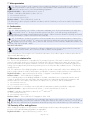
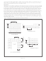
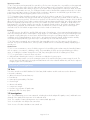
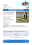
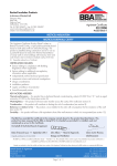
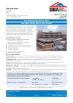
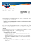
BASF Polyurethanes UK Limited APPROVAL INSPECTION TESTING CERTIFICATION Alfreton Trading Estate Wimsey Way Somercotes Alfreton Derbyshire DE55 4NL Tel: 01773 601166 Fax: 01773 602089 TECHNICAL APPROVALS FOR CONSTRUCTION Agrément Certificate 13/5002 e-mail: [email protected] website: www.walltite.basf.co.uk Product Sheet 1 BASF POLYURETHANES BASF WALLTITE CV 100 CAVITY WALL INSULATION This Agrément Certificate Product Sheet (1) relates to BASF Walltite CV 100 Cavity Wall Insulation, a rigid polyurethane foam injected in liquid form, for use in external masonry walls up to and including 12 m in height, with cavity widths not less than 40 mm, in new and existing domestic and non-domestic buildings. (1) Hereinafter referred to as ‘Certificate’. CERTIFICATION INCLUDES: • factors relating to compliance with Building Regulations where applicable • factors relating to additional non-regulatory information where applicable • independently verified technical specification • assessment criteria and technical investigations • design considerations • installation guidance • regular surveillance of production • formal three-yearly review. KEY FACTORS ASSESSED Thermal performance — the product’s thermal conductivity (90/90 value) ranges from 0.026 W·m–1·K–1 to 0.028 W·m–1·K–1, depending on thickness (see section 6). Water penetration — the product will resist the transfer of precipitation to the inner leaf (see section 7). Condensation — the product will contribute to limiting the risk of surface condensation (see section 8). Durability — the durability of the product is satisfactory and it will have a life equivalent to that of the structure in which it is incorporated (see section 12). The BBA has awarded this Certificate to the company named above for the product described herein. This product has been assessed by the BBA as being fit for its intended use provided it is installed, used and maintained as set out in this Certificate. On behalf of the British Board of Agrément Date of First issue: 20 May 2013 John Albon — Head of Approvals Greg Cooper Energy and Ventilation Chief Executive The BBA is a UKAS accredited certification body — Number 113. The schedule of the current scope of accreditation for product certification is available in pdf format via the UKAS link on the BBA website at www.bbacerts.co.uk Readers are advised to check the validity and latest issue number of this Agrément Certificate by either referring to the BBA website or contacting the BBA direct. British Board of Agrément Bucknalls Lane Watford Herts WD25 9BA ©2013 Page 1 of 12 tel: 01923 665300 fax: 01923 665301 e-mail: [email protected] website: www.bbacerts.co.uk Regulations In the opinion of the BBA, BASF Walltite CV 100 Cavity Wall Insulation, if installed, used and maintained in accordance with this Certificate, will meet or contribute to meeting the relevant requirements of the following Building Regulations (the presence of a UK map indicates that the subject is related to the Building Regulations in the region or regions of the UK depicted): The Building Regulations 2010 (England and Wales) (as amended) Requirement: C2(a) Resistance to moisture Comment: Requirement: C2(b) Resistance to moisture Comment: Requirement: C2(c) Resistance to moisture Comment: Requirement: L1(a)(i) Conservation of fuel and power Comment: Regulation: 7 Materials and workmanship Comment: Regulation: 26 CO2 emission rates for new buildings The product contributes to meeting this Requirement. See section 7.1 of this Certificate. The product contributes to meeting this Requirement. See sections 7.1 and 7.2 of this Certificate. The product contributes to meeting this Requirement. See sections 8.1 and 8.3 of this Certificate. The product contributes to meeting this Requirement. See section 6 of this Certificate. The product is an acceptable material. See section 12 and the Installation part of this Certificate. The product can contribute to meeting this Regulation. See section 6 of this Certificate. Comment: The Building (Scotland) Regulations 2004 (as amended) Regulation: 8(1) Regulation: Standard: 9 2.6 3.4 3.10 3.15 6.1(b) 6.2 7.1(a)(b) Statement of sustainability The product can contribute to meeting the relevant requirements of Regulation 9, Standards 1 to 6, and therefore will contribute to a construction meeting a bronze level of sustainability as defined in this Standard. In addition, the product can contribute to a construction meeting a higher level of sustainability as defined in this Standard, with reference to clauses 7.1.4(1)(2) [Aspects 1(1)(2) and 2(1)], 7.1.6(1)(2) [Aspects 1(1)(2) and 2(1)] and 7.1.7(1)(2) [Aspect 1(1)(2)]. See section 6.2 of this Certificate. Comment: Regulation: Carbon dioxide emissions Building insulation envelope This product contributes to satisfying clauses, or parts of, 6.1.1(1), 6.1.2(2), 6.1.6(1), 6.1.10(2), 6.2.1(1)(2), 6.2.3(1), 6.2.4(2), 6.2.5(2), 6.2.6(1), 6.2.7(1), 6.2.8(1)(2), 6.2.9(1)(2), 6.2.10(1)(2), 6.2.11(1)(2), 6.2.12(2) and 6.2.13(1)(2) of these Standards. See section 6 of this Certificate. Comment: Standard: Condensation The product contributes to satisfying this Standard, with reference to clauses 3.15.1(1)(2), 3.15.4(1)(2) and 3.15.5(1)(2). See sections 8.2 and 8.3 of this Certificate. Comment: Standard: Standard: Precipitation The product contributes to satisfying this Standard, with reference to clause 3.10.1(1)(2), provided it complies with the conditions set out in sections 7.1 and 7.2 of this Certificate. Comment: Standard: Moisture from the ground The product contributes to satisfying this Standard, with reference to clause 3.4.1(1)(2). See section 7.1 of this Certificate. Comment: Standard: Building standards applicable to construction Spread to neighbouring buildings The product is not non-combustible but may be used in walls of domestic and non-domestic buildings in accordance with the exceptions permitted in the Standard, with reference to clauses 2.6.5(1) and 2.6.6(2). See section 9.5 of this Certificate. Comment: Standard: Fitness and durability of materials and workmanship The product can contribute to a construction satisfying this Regulation. See section 12 and the Installation part of this Certificate. Comment: 12 Building standards applicable to conversions Comments made in relation to the product under Regulation 9 Standards 1 to 6 also apply to this Regulation, with reference to clause 0.12.1(1)(2) and Schedule 6(1)(2). Comment: (1) Technical Handbook (Domestic). (2) Technical Handbook (Non-Domestic). The Building Regulations (Northern Ireland) 2012 Regulation: 23 Fitness of materials and workmanship Comment: Regulation: 28(a) Resistance to moisture and weather Comment: Regulation: 28(b) Resistance to moisture and weather Comment: The product is an acceptable material. See section 12 and the Installation part of this Certificate. The product contributes to meeting this Regulation. See section 7.1 of this Certificate. The product contributes to meeting this Regulation. See sections 7.1 and 7.2 of this Certificate. Page 2 of 12 Regulation: 29 Condensation Comment: Regulation: Regulation: 39(a)(i) 40(2) Conservation measures Target carbon dioxide emission rate The product contributes to meeting this Regulation. See section 8.3 of this Certificate. Comment: The product contributes to meeting these Regulations. See section 6 of this Certificate. Construction (Design and Management) Regulations 2007 Construction (Design and Management) Regulations (Northern Ireland) 2007 Information in this Certificate may assist the client, CDM co-ordinator, designer and contractors to address their obligations under these Regulations. See section: 3 Delivery and site handling (3.1 and 3.3) of this Certificate. Additional Information NHBC Standards 2013 NHBC accepts the use of BASF Walltite CV 100 Cavity Wall Insulation, other than in very severe exposure locations with fair-faced masonry, provided it is installed, used and maintained in accordance with this Certificate, in relation to NHBC Standards, Chapter 6.1, External masonry walls. Technical Specification 1 Description 1.1 BASF Walltite CV 100 Cavity Wall Insulation is a purple-coloured, polyurethane foam compound. 1.2 It is injected as a syrup from a hand gun into the wall through nominal 12 mm diameter holes spaced in a predetermined pattern. 1.3 The product has an installed density in the range of 35 kg·m–3 to 45 kg·m–3. 2 Manufacture 2.1 The material is foamed in-situ by mixing together isocyanate and resin components. The foam mix produced is soft and fluid but quickly expands and hardens to a rigid foam mass. 2.2 As part of the assessment and ongoing surveillance of product quality, the BBA has: • agreed with the manufacturer the quality control procedures and product testing to be undertaken • assessed and agreed the quality control operated over batches of incoming materials • monitored the production process and verified that it is in accordance with the documented process • evaluated the process for management of nonconformities • checked that equipment has been properly tested and calibrated • undertaken to carry out the above measures on a regular basis through a surveillance process, to verify that the specifications and quality control operated by the manufacturer are being maintained. 2.3 The management system of BASF Polyurethanes UK Limited has been assessed and registered as meeting the requirements of BS EN ISO 9001 : 2008 by DQS GmbH (Certificate 099501 QM). 3 Delivery and site handling 3.1 The two components are delivered to site in drums (up to 250 kg capacity) bearing the product name and batch number. 3.2 Drums should be stored in areas ideally above 10°C and away from possible ignition sources. The drums must be protected from frost. 3.3 The isocyanate and polyol (a component contained in the resin) are classified as ‘harmful’ and ‘irritant’ respectively under The Chemicals (Hazard Information and Packaging for Supply) Regulations 2009 (CHIP4)/ Classification, Labelling and Packaging of Substances and Mixtures (CLP Regulation) 2009, and the packaging bears the appropriate hazard warning labels. When cured, BASF Walltite CV 100 Cavity Wall Insulation does not constitute a hazard. Assessment and Technical Investigations The following is a summary of the assessment and technical investigations carried out on BASF Walltite CV 100 Cavity Wall Insulation. Page 3 of 12 Design Considerations 4 General 4.1 BASF Walltite CV 100 Cavity Wall Insulation is satisfactory for use as an injected cavity wall insulation and is effective in reducing the thermal transmittance (U value) of external cavity walls, with masonry inner and outer leaves (where masonry includes clay and calcium silicate bricks, concrete blocks, and natural and reconstituted stone blocks). The product is for use in new and existing domestic and non-domestic buildings up to and including 12 m in height, with cavity widths not less than 40 mm nor greater than 200 mm. It is essential that such walls are designed and constructed to incorporate the precautions given in this Certificate to prevent moisture penetration. 4.2 The suitability of walls for insulation must be assessed in accordance with BS EN 14318-2 : 2013. 4.3 This Certificate covers the use of the product in any exposure zone(1), subject to the following conditions being met, which are particularly important in areas which may experience severe or very severe driving rain: • a site survey should be carried out prior to installation (see sections 13 and 14). • the minimum cavity width must be not less than 40 mm • walls must be in good state of repair and show no evidence of frost damage • mortar joints must not show evidence of more than hairline cracking. Raked or recessed mortar joints should be avoided in very severe exposure areas. (1) Exposure zones defined in BRE Report BR 262 : 2002 Partial filling — omitted areas 4.4 Whenever practicable, all of the cavity space from ground level to the roof or gable copings should be filled, except: • when separately insulating semi-detached or terraced properties • up to the underside of a horizontal boundary, other than the roof, where that horizontal boundary is protected by a cavity tray or similar waterproof barrier • when treating properties where the wall to be insulated is below a waterproof cladding (eg tile hung) and this cladding either extends up to the roof or is protected at the top by other means (eg window sills) • when treating areas of wall where access for drilling may be limited by features such as carports and conservatories, as defined in sections 17.10 and 17.11. Existing buildings 4.5 In an existing building, the product may be installed only: • where there are no signs of dampness on the inner face of the cavity wall, other than those caused solely by condensation, and • where the cavity is not being used as a source of combustion air or as a flue for ventilation purposes. New buildings 4.6 New buildings subject to the national Building Regulations should be constructed in accordance with the relevant recommendations of: • BS 8000-3 : 2001 • BS EN 1996-1-1 : 2005, BS EN 1996-1-2 : 2005, BS EN 1996-2 : 2006 and BS EN 1996-3 : 2006 and their respective UK National Annexes. 4.7 Other new buildings not subject to regulatory requirements should also be built in accordance with the Standards identified in section 4.6. 4.8 In a new building where the product is to be installed: • cavity battens or boards must be used to reduce the amount of mortar droppings left in the cavity • injection of the product is to be left until the cavity is sealed from the weather, ie the roof is in place and the window and door openings are sealed. 5 Practicability of installation The product must be installed by operatives trained and approved by the Certificate holder and subsequently approved by the BBA. The Certificate holder operates an Approved Installer Scheme(1) for this system under which the installers are approved, registered and regularly reviewed by the Certificate holder to demonstrate that they are competent to carry out installations of the system in accordance with this Certificate. Details of Approved Installers are available from the Certificate holder. Approved Installers are responsible for each installation of the product that they undertake (see section 15). (1) The Certificate holder’s records relating to their Approved Installer Scheme will be audited annually by the BBA as part of its programme of surveillance. Page 4 of 12 6 Thermal performance 6.1 Calculations of the thermal transmittance (U value) should be carried out in accordance with BS EN ISO 6946 : 2007 and BRE Report BR 443 : 2006, using the thermal conductivity (90/90 values) shown in Table 1. Table 1 Thermal conductivity Insulation thickness (mm) Thermal conductivity (W·m–1·K–1) <80 0.028 80 to 120 0.027 >120 0.026 6.2 The U value of a typical brick and block cavity wall construction will depend on the cavity width and the insulating value of the internal block leaf finish. Calculated U values for sample constructions are given in Table 2 for existing buildings and in Table 3 for new buildings. Table 2 Example cavity wall U values — Existing/retained walls Cavity width/insulation thickness (mm) U values (W·m–2·K–1)(1) 13 mm dense plaster(2) Plasterboard on dabs 100 mm dense block(3) 100 mm AAC block(4) 40 0.56 0.39 50 0.47 0.34 75 0.34 0.26 100 0.25 0.21 125 0.20 0.17 (1) Assumes 102 mm thick brick outer leaf, mild steel double-triangle ties (12.5 mm2) at 2.5 m2 and 6.7% mortar (0.88 W·m–1·K–1) bridging inner block leaf. (2) Dense plaster 0.57 W·m–1·K–1. (3) Dense block at 1.13 W·m–1·K–1. (4) AAC block at 0.12 W·m–1·K–1. Table 3 Example cavity wall U values(1) — New buildings U value requirement (W·m–2·K–1) Insulation thickness (mm) 13 mm dense plaster(2) Plasterboard on dabs 100 mm dense block 100 mm AAC block(4) (3) 0.19 125 110 0.25 95 80 0.26 95 75 0.27 90 70 0.30 80 60 0.35 70 50 (1) Assumes 102 mm thick brick outer leaf, stainless steel double-triangle ties (12.5 mm2) at 2.5 m2 and 6.7% mortar (0.88 W·m–1·K–1) bridging inner block leaf. (2) Dense plaster 0.57 W·m–1·K–1. (3) Dense block at 1.13 W·m–1·K–1. (4) AAC block at 0.12 W·m–1·K–1. 6.3 The product can maintain, or contribute to maintaining, continuity of thermal insulation at junctions between elements. For Accredited Construction Details, the corresponding psi values in BRE Information Paper IP 1/06, Table 3, may be used in carbon emission calculations in Scotland and Northern Ireland. Detailed guidance for other junctions and on limiting heat loss by air infiltration can be found in: England and Wales — Approved Documents to Part L, and for new thermal elements to existing buildings, Accredited Construction Details (version 1.0). Also see SAP 2009 The Government’s Standard Assessment Procedure for Energy Rating of Dwellings, Appendix K and the iSBEM User Manual for new-build Scotland — Accredited Construction Details (Scotland) Northern Ireland — Accredited Construction Details (version 1.0). Page 5 of 12 7 Water penetration 7.1 When the product is used in situations where it bridges the damp-proof course (dpc) in walls, dampness from the ground will not pass through to the inner leaf provided the wall is detailed in accordance with the requirements and provisions of the national Building Regulations: England and Wales — Approved Document C, section 5 Scotland — Mandatory Standard 3.4, clause 3.4.1(1)(2) (1) Technical Handbook (Domestic). (2) Technical Handbook (Non-Domestic). Northern Ireland — Technical Booklet C, Section 6. 7.2 When the product is properly installed in accordance with this Certificate, it will resist the transfer of precipitation to the inner leaf. 8 Condensation Surface condensation 8.1 Walls will limit the risk of surface condensation adequately when the thermal transmittance (U value) does not exceed 0.7 W·m–2·K–1 at any point and the junctions with floors, roofs and openings are designed in accordance with Limiting thermal bridging and air leakage : Robust construction details for dwellings and similar buildings (TSO 2002), IP 1/06 or section 6.3 of this Certificate. 8.2 For buildings in Scotland, constructions will be acceptable where the thermal transmittance (U value) of the wall does not exceed 1.2 W·m–2·K–1 at any point and openings and junctions with other elements comply with the guidance given in BS 5250 : 2011, Annex G and section 6.3 of this Certificate. Additional information can be found in BRE Report BR 262 : 2002. Interstitial condensation 8.3 Walls will limit the risk of interstitial condensation adequately when they are designed and constructed in accordance with BS 5250 : 2011, Annexes D and G and the relevant guidance. 8.4 For the purposes of assessing the risk of interstitial condensation, the product’s vapour resistivity may be taken as approximately 660 MN·s·g–1·m–1. 9 Behaviour in relation to fire 9.1 The use of the product does not prejudice the fire resistance properties of the wall. It is unlikely to become ignited within the cavity when used in the context of this Certificate. If fire does penetrate into the cavity, the amount of air present will be insufficient to support combustion. However, the instructions contained in this Certificate relating to the sealing of an uncapped cavity and removing insulant present in the loft space after installation (section 17.9) must be carefully followed. 9.2 The requirements of the Building Regulations relating to fire spread in cavity walls can be met in buildings of all purpose groups without the need for cavity barriers, provided the construction complies with the provisions detailed in: England and Wales — Approved Document B, Volume 1, Diagram 13 and Volume 2, Diagram 34 Northern Ireland — Technical Booklet E, Diagram 4.5. 9.3 For buildings subject to the Building Standards in Scotland, cavity barriers are not required to limit the area of a cavity or at junctions with other wall cavities, but cavity barriers are required around openings, penetrations and junctions with roof or floor cavities, with reference to clauses 2.4.1(1)(2), 2.4.2(1)(2), 2.6.5(1) and 2.6.6(2). (1) Technical Handbook (Domestic). (2) Technical Handbook (Non-Domestic). 9.4 For constructions not covered by sections 9.2 and 9.3 cavity barriers must be provided to comply with: England and Wales — Approved Document B, Volume 1, Section 6 and Volume 2, Section 9 Scotland — Mandatory Standard 2.4, clauses 2.4.1(1)(2) and 2.4.2(1)(2) (1) Technical Handbook (Domestic). (2) Technical Handbook (Non-Domestic). Northern Ireland — Technical Booklet E, Paragraphs 4.36 to 4.39. 9.5 The product is not classified as ‘non-combustible’ but may be used in a wall on or less than 1 m from a relevant boundary, where they are installed in a cavity that is between two leaves of masonry or concrete at least 75 mm thick, and which has a cavity barrier around all openings in the wall and at the top of the wall-head. 10 Proximity of flues and appliances When installing the product in close proximity to certain flue pipes and/or heat producing appliances, the relevant provisions of the national Building Regulations are applicable: England and Wales — Approved Document J, sections 1 to 4 Page 6 of 12 Scotland — Mandatory Standard 3.19, clauses 3.19.1(1)(2) to 3.19.9(1)(2) (1) Technical Handbook (Domestic). (2) Technical Handbook (Non-Domestic). Northern Ireland — Technical Booklet L, Sections 1 to 6. 11 Maintenance As the product is confined within the wall cavity and has suitable durability (see section 12), maintenance is not required. 12 Durability The product is unaffected by the normal conditions in a wall and is durable, rot proof, water resistant and sufficiently stable to remain effective as insulation for the life of the building. Installation 13 Site assessment Prior to the installation, an assessment is carried out by a trained assessor, who may also be the installing technician, to ascertain the suitability of the property or properties to receive BASF Walltite CV 100 Cavity Wall Insulation. An assessment report is prepared and held at the installer’s offices. Particular problems are specifically identified and any reasons for rejection of the work noted. At this stage the assessor and the party commissioning the work must identify, and agree in writing as appropriate, any areas of the wall that will not be filled (see section 17.10) and any special requirements for making good (see section 17.8). 14 Site preparation 14.1 The installing operative ensures that the property has been correctly assessed and is suitable for insulation with the product. Any problems encountered during installation which prevent compliance with this Certificate are referred to the installation company before proceeding. 14.2 Essential ventilation openings, such as those providing combustion air or underfloor ventilation, and all flues in the cavity wall must be checked. If adequate sleeving or other cavity closures are not present, installation must not proceed until these openings have been sleeved or otherwise modified to prevent blockage by the insulant. 14.3 All gaps and cracks in the inner and outer leaves and the tops of uncapped cavities are sealed where possible to limit any escape of the material during installation. 15 Approved installers Installation of the product is carried out by the Certificate holder or their approved installers. An approved installer is defined as a company: • equired to satisfy an initial site installation check by the BBA following approval by the Certificate holder and is subject to the BBA Assessment and Surveillance Scheme for Installation of Cavity Wall Insulation • approved by the Certificate holder and the BBA to install the product • having undertaken to comply with the Certificate holder’s installation procedure • employing technicians who have been issued with appropriate identity cards by the Certificate holder; at least one member of each installation team must carry a card • subject to inspections by the Certificate holder. The Certificate holder oversees the activities of approved installers operating under the BBA Surveillance Scheme for Cavity Wall Insulation. It is a requirement that the Certificate holder undertakes inspections to each card-carrying technician using their product and maintains records, as detailed in the BBA Assessment and Surveillance Scheme for BBA Approved Installers of Cavity Wall Insulation. 16 Supervision 16.1 Installation of the product should be carried out in accordance with the BBA Assessment and Surveillance Scheme for Installation of Cavity Wall Insulation. 16.2 During installation, the following simple checks can be made as an aid to determining that the installation conforms to the certificated method: • the pattern of holes complies with the description given in section 17 • injection of material takes place in each hole, to complete the filling of the cavity space. 17 Procedure Injection equipment 17.1 The installer provides all necessary materials and equipment for installation, plus materials for making good the walls after installation of the product. Injection equipment comprises a proportioning unit of two identical air-driven pumps, which are connected and give an accurately metered supply of the isocyanate and resin components to the Page 7 of 12 injection gun. Each air-driven pump supplies a separate component and has a fixed cross-sectional area to give a 1:1 ratio by volume. A 10 mm diameter nozzle is used to inject the mixed components into the cavity. A stroke counter is fitted to the proportioning unit to monitor the correct number of strokes. Injection holes 17.2 Holes of 12 mm diameter are drilled in the outer leaf at the intersections of mortar joints. In general, a staggered drilling pattern is used, with holes approximately 0.72 m apart horizontally (ie three bricks) and 0.48 m apart vertically (ie six bricks) for cavity widths between 40 mm and 150 mm, and approximately 0.48 m apart horizontally (ie two bricks) and approximately 0.40 m apart vertically (ie five bricks) for cavity widths greater than 150 mm. At door and window frames, extra holes must be drilled around these areas to ensure that they are completely filled. To minimise the risk of foam extrusion to the roof space, the highest row of holes is drilled approximately 0.24 m (three bricks) below the design height of the insulation and approximately 0.48 m apart horizontally (ie two bricks) for cavity widths between 40 mm and 150 mm, and approximately 0.36 m apart horizontally (ie one and a half bricks) for cavity widths greater than 150 mm. When treating semi-detached or terraced houses, a vertical column of holes is drilled at approximately 0.32 m (four bricks) centres for cavity widths between 40 mm and 150 mm, and approximately 0.24 m (three bricks) centres for cavity widths greater than 150 mm, 0.36 m (one and a half brick) in from the party line between properties. Where necessary, air bricks are removed and replaced with a sleeved type. Care must be taken during the drilling process to ensure that no damage is done to any dpc at the various building details, eg above windows (see Figures 1 and 2). Figure 1 Drilling patterns for cavity widths between 40 mm and 150 mm top of insulation at roof level 0.24 m (three bricks) 0.48 m (six bricks) 0.72 m (three bricks) 0.48 m (two bricks) (3) Drilling pattern at roof level dpc dpc 0.32 m (four bricks) door or window opening 0.24 m typical (one brick) (2) Door and window frame drilling pattern Page 8 of 12 party line 0.32 m (four bricks) 0.48 m (two bricks) distance greater above door or window to avoid lintel (1) Staggered drilling pattern dpc dpc 0.36 m (1½ bricks) (4) Drilling pattern at a party wall Figure 2 Drilling patterns for cavity widths between 150 mm and 200 mm top of insulation at roof level 0.24 m (three bricks) 0.4 m (five bricks) 0.48 m (two bricks) 0.36 m (1½ bricks) (3) Drilling pattern at roof level dpc dpc (1) Staggered drilling pattern partyline 0.24 m (three bricks) 0.36 m (1½ bricks) door or window opening 0.24 m (three bricks) dpc dpc 0.36 m (1½ bricks) (4) Drilling pattern at a party wall (2) Door and window frame drilling pattern Pre-injection checks 17.3 The isocyanate and resin components are temperature conditioned before starting the machine. Party Line 17.4 When dealing with the dividing line of an attached property which is not being insulated it is essential to leave a vertical boundary of polyurethane foam adjacent to the neighbouring cavity. The 10 mm diameter straight nozzle is attached to the mixing head and the primary heater and hose line temperatures are set. Higher temperatures increase foam reactivity and minimise sideways flow. Since reaction time is shorter, a bag test can be carried out in a small bag, as used in BS 5617 : 1985 Appendix B. The foam is injected into the transparent polythene bag for two strokes of the pump, the typical injection time into one hole for a boundary area. The mix reaction is timed as it enters the bag and a note made (in seconds) of the cream time, rise time and tack free time. Once the foam has set, it is examined for sticky patches which could indicate a component surge. If it is good, another shot is injected and the foam allowed to cure. It is then checked for surface wrinkling, cut in half and the internal cell structure checked for blow holes or splits. When the bag tests are satisfactory, the product density is measured and the shrinkage is determined as outlined in BS 5617 : 1985, Appendix B, and should not be more than 1%. Main sections of the wall 17.5 A foam quality check for the major area is carried out after injection of the boundary areas. A 10 mm flexible nozzle with a 45-degree end is used; the primary heater and hose line temperatures are set. The above bag tests are repeated, with an appropriate number of strokes of the pump. Once the tests have again been carried out satisfactorily, the machine is set up to commence foam injection of the major area. Polyurethane foam should not be injected into a hole for more than its cream time. Page 9 of 12 Injection procedure 17.6 For a property with a party-wall, the vertical line of holes next to the party line is injected first, working upwards from the base, using two strokes per hole. After each fill, an indicator stick is inserted into each hole to show that injection has taken place and to mark the presence of the foam. When all party-wall lines have been filled, the heater and hose line temperatures are reset. The 45-degree flexible nozzle is fitted and the equipment allowed to cool down to the lower temperature. Injection of the major areas now begins, adjacent to a sealed end (eg a door frame or the band of foam at a party line) beginning at the lowest row of holes. 17.7 Polyurethane foam should be injected into each hole for less than its cream time. The complete row is then injected, with the indicator sticks being inserted and any `topping-up’ necessary being carried out at the same time. (A typical ‘top-up’ shot is two strokes.) The next row is injected, once the tack free time elapses, starting in the hole directly above the last one filled. This procedure continues until the total area (starting and finishing at a sealed end) has been filled to the required height. At the top row of holes, the number of injection strokes is reduced, to avoid intrusion of foam against the roof structure. Smaller shots may also be required around windows, door frames and ducts. When filling has been completed, the total number of strokes recorded on the counter is noted, plus the total weight of chemical used. This will enable an approximate check to be made on foam density. Finishing 17.8 After injection, the drill holes are fully filled with mortar of a similar type, colour, texture and weathertightness to that of the existing wall. Where a wall requires a high degree of colour matching, the level of finish matching should be agreed in writing during the site assessment. All trunked air vents eg those providing underfloor ventilation and combustion air for heating appliances are checked — any obstructions must be cleared. All flues must be carefully checked by an appropriate test (eg a smoke test) to verify that they are clear and unobstructed. 17.9 If the cavity is uncapped, any insulant which has expanded over the top of the cavity into the loft space is removed. The top of the insulant is then, where possible, isolated from the roof structure by suitably shaped plugs of mineral wool. Omitted areas 17.10 In some circumstances, access for drilling injection holes and filling with insulation may be limited by features such as carports, conservatories, cladding or tiling. The practicability of safely accessing and making good these areas, or installing the insulation through the inner leaf, may outweigh the benefits of insulating these areas. 17.11 It is permissible to omit such areas only when: • a full justification detailing the reasons to omit areas is included in the survey report • the assessor obtains written consent for omitting any areas of the wall from the party commissioning the work. The assessor must verify that heat loss through uninsulated areas will not be reduced and that they will also be subject to a slightly higher risk of condensation. Technical Investigations 18 Tests Tests were carried out on BASF Walltite CV 100 Cavity Wall Insulation and the results assessed to determine: • thermal conductivity • adhesion between foam and masonry • foam density • water vapour permeability of the foam • shear strength • dimensional stability • compressive strength • resistance to penetration of liquid water • adequacy of fill of a cavity space. 19 Investigations 19.1 The manufacturing process was examined, including the methods adopted for quality control, and details were obtained of the quality and composition of the materials used. 19.2 The company’s training arrangements were examined and approved. 19.3 A condensation risk analysis was carried out. 19.4 A series of U value calculations was carried out. Page 10 of 12 Bibliography BS 5250 : 2011 Code of practice for control of condensation in buildings BS 5617 : 1985 Specification for urea-formaldehyde (UF) foam systems suitable for thermal insulation of cavity walls with masonry or concrete inner and outer leaves BS 8000-3 : 2001 Workmanship on building sites — Code of practice for masonry BS EN 1996-1-1 : 2005 Eurocode 6 — Design of masonry structures — General rules for reinforced and unreinforced masonry structures NA to BS EN 1996-1-1 : 2005 UK National Annex to Eurocode 6 — Design of masonry structures — General rules for reinforced and unreinforced masonry structures BS EN 1996-1-2 : 2005 Eurocode 6 — Design of masonry structures — General rules — Structural fire design NA to BS EN 1996-1-2 : 2005 UK National Annex to Eurocode 6 — Design of masonry structures — General rules — Structural fire design BS EN 1996-2 : 2006 Eurocode 6 — Design of masonry structures — Design considerations, selection of materials and execution of masonry NA to BS EN 1996-2 : 2006 UK National Annex to Eurocode 6 — Design of masonry structures — Design considerations, selection of materials and execution of masonry BS EN 1996-3 : 2006 Eurocode 6 — Design of masonry structures — Simplified calculation methods for unreinforced masonry structures NA to BS EN 1996-3 : 2006 UK National Annex to Eurocode 6 — Design of masonry structures — Simplified calculation methods for unreinforced masonry structures BS EN ISO 6946 : 2007 Building components and building elements — Thermal resistance and thermal transmittance — Calculation method BS EN ISO 9001 : 2008 Quality Management Systems — Requirements BRE Information Paper IP 1/06 Assessing the effects of thermal bridging at junctions and around openings BRE Report (BR 262 : 2002) Thermal insulation: avoiding risks BRE Report (BR 443 : 2006) Conventions for U value calculations Page 11 of 12 Conditions of Certification 20 Conditions 20.1 This Certificate: • relates only to the product/system that is named and described on the front page • is issued only to the company, firm, organisation or person named on the front page — no other company, firm, organisation or person may hold or claim that this Certificate has been issued to them • is valid only within the UK • has to be read, considered and used as a whole document — it may be misleading and will be incomplete to be selective • is copyright of the BBA • is subject to English Law. 20.2 Publications, documents, specifications, legislation, regulations, standards and the like referenced in this Certificate are those that were current and/or deemed relevant by the BBA at the date of issue or reissue of this Certificate. 20.3 This Certificate will remain valid for an unlimited period provided that the product/system and its manufacture and/or fabrication, including all related and relevant parts and processes thereof: • are maintained at or above the levels which have been assessed and found to be satisfactory by the BBA • continue to be checked as and when deemed appropriate by the BBA under arrangements that it will determine • are reviewed by the BBA as and when it considers appropriate. 20.4 The BBA has used due skill, care and diligence in preparing this Certificate, but no warranty is provided. 20.5 In issuing this Certificate, the BBA is not responsible and is excluded from any liability to any company, firm, organisation or person, for any matters arising directly or indirectly from: • the presence or absence of any patent, intellectual property or similar rights subsisting in the product/system or any other product/system • the right of the Certificate holder to manufacture, supply, install, maintain or market the product/system • actual installations of the product/system, including their nature, design, methods, performance, workmanship and maintenance • any works and constructions in which the product/system is installed, including their nature, design, methods, performance, workmanship and maintenance • any loss or damage, including personal injury, howsoever caused by the product/system, including its manufacture, supply, installation, use, maintenance and removal • any claims by the manufacturer relating to CE marking. 20.6 Any information relating to the manufacture, supply, installation, use, maintenance and removal of this product/ system which is contained or referred to in this Certificate is the minimum required to be met when the product/system is manufactured, supplied, installed, used, maintained and removed. It does not purport in any way to restate the requirements of the Health and Safety at Work etc. Act 1974, or of any other statutory, common law or other duty which may exist at the date of issue or reissue of this Certificate; nor is conformity with such information to be taken as satisfying the requirements of the 1974 Act or of any statutory, common law or other duty of care. British Board of Agrément Bucknalls Lane Watford Herts WD25 9BA ©2013 Page 12 of 12 tel: 01923 665300 fax: 01923 665301 e-mail: [email protected] website: www.bbacerts.co.uk