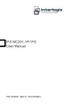
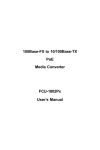
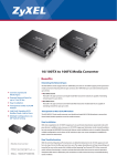
1
GE
Security
MC100FX-TX-PoE
Media Converter
User Manual
P/N 1069178 • REV 1.01 • ISS 03MAR10
Copyright
© 2010 GE Security, Inc.
This document may not be copied in whole or in part or otherwise
reproduced without prior written consent from GE Security, Inc.,
except where specifically permitted under US and international
copyright law.
Disclaimer
The information in this document is subject to change without notice.
GE Security, Inc. (“GE Security”) assumes no responsibility for
inaccuracies or omissions and specifically disclaims any liabilities,
losses, or risks, personal or otherwise, incurred as a consequence,
directly or indirectly, of the use or application of any of the contents
of this document. For the latest documentation, contact your local
supplier or visit us online at www.gesecurity.com.
This publication may contain examples of screen captures and
reports used in daily operations. Examples may include fictitious
names of individuals and companies. Any similarity to names and
addresses of actual businesses or persons is entirely coincidental.
Trademarks and
patents
GE and the GE monogram are trademarks of General Electric
Company.
Other trade names used in this document may be trademarks or
registered trademarks of the manufacturers or vendors of the
respective products.
Intended use
FCC compliance
Use this product only for the purpose it was designed for; refer to the
data sheet and user documentation for details. For the latest product
information, contact your local supplier or visit us online at
www.gesecurity.com.
This equipment has been tested and found to comply with the limits
for a Class A digital device, pursuant to part 15 of the FCC Rules.
These limits are designed to provide reasonable protection against
harmful interference when the equipment is operated in a
commercial environment. This equipment generates, uses, and can
radiate radio frequency energy and, if not installed and used in
accordance with the instruction manual, may cause harmful
interference to radio communications.
You are cautioned that any changes or modifications not expressly
approved by the party responsible for compliance could void the
user's authority to operate the equipment.
Regulatory
information
N4131
Manufacturer
GE Security, Inc.
HQ and regulatory responsibility:
GE Security, Inc., 8985 Town Center Parkway,
Bradenton, FL 34202, USA
EU authorized manufacturing representative:
GE Security B.V., Kelvinstraat 7,
6003 DH Weert, The Netherlands
European Union
directives
2002/96/EC (WEEE directive): Products marked with this symbol
cannot be disposed of as unsorted municipal waste in the European
Union. For proper recycling, return this product to your local supplier
upon the purchase of equivalent new equipment, or dispose of it at
designated collection points. For more information see:
www.recyclethis.info.
Contact information
For contact information see our Web site: www.gesecurity.com.
For contact information see our Web site: www.gesecurity.eu.
Content
Chapter 1 Introduction 1
Package Contents 2
Introduction 2
Chapter 2 Hardware Installation 9
Installing the Converter 9
PoE functions 10
Chapter 3 Specifications 13
MC100FX-TX-PoE Technical Specifications 13
Cable Connection Specifications 15
MC100FX-TX-PoE Media Converter User Manual
i
ii
MC100FX-TX-PoE Media Converter User Manual
Chapter 1
Introduction
The GE Security MC100FX-TX-PoE 100Base-FX to 10/100Base-TX PoE Media
Converter is a great solution for remote network equipment deployment. It
integrates the following two networking technologies:
•
Media Conversion: 100Base-FX to 10/100Base-TX
•
Power over Ethernet: Power Sourcing Equipment (PSE), PoE Injector
Providing both PoE and Fiber Optical interfaces, the MC100FX-TX-PoE is ideal
for service providers, campuses and public areas requiring deployment of
PoE devices at wireless access points for IP-based surveillance cameras or IP
phones easily, efficiently and cost effectively.
MC100FX-TX-PoE Media Converter User Manual
1
Chapter 1: Introduction
Package Contents
Your MC100FX-TX-PoE carton should contain the following items:
•
100Base-FX to 10/100Base-TX PoE Media Converter x1
•
User's Manual x1
If any item is missing or damaged, please consult the dealer from whom you
purchased your PoE Media Converter.
Introduction
Thank you for purchasing the GE MC100FX-TX-PoE 10/100Mbps Ethernet
Twisted pair to 100Base-FX Fiber-optic PoE Bridge Converter. This converter
is used to convert one type media signal to other equivalent type. The two
type segments connect easily, efficiently and inexpensively. The converter
provides a Power over Ethernet power injector function, which is able to
drive one IEEE 802.3af compliant powered device.
About the Power over Ethernet Injector
The MC100FX-TX-PoE is an IEEE 802.3af Power over Ethernet Injector that
provides DC 48V over Ethernet cables (power supply not provided). The
MC100FX-TX-PoE IEEE 802.3af Power over Ethernet Injector inserts DC
Voltage into Cat.5 cable, allowing the cable between the Injector (MC100FXTX-PoE) and PoE PD (Powered Device) to transfer data and power
simultaneously. The maximum distance between the Injector (MC100FX-TXPoE) and PoE PD is 100 meters. When a MC100FX-TX-PoE is installed, it
combines the Ethernet digital data with power over the twisted pair cables
as an IEEE 802.3af Power over Ethernet Injector. The IEEE 802.3af Power over
Ethernet splitter can separate the digital data and the power into two
outputs.
NOTE: This product is intended to be supplied by a UL Listed Direct Plug-In
Power Unit marked "Class 2" or "LPS" and output rated 48 VDC.
2
MC100FX-TX-PoE Media Converter User Manual
Chapter 1: Introduction
When an IEEE 802.3af Power over Ethernet device is installed the system
administrator only has to use a single RJ-45 Ethernet cable to carry both
power and data signals to each device.
Model List
The PoE Media Converter model is:
•
MC100FX-TX-PoE: with on board SC/Multi-mode fiber connector, up to
2km
Media Converter Features
•
Complies with the IEEE 802.3, IEEE 802.3u 10/100Base-TX, 100Base-FX,
IEEE 802.3af Power Over Ethernet standard
•
Auto-Negotiation for 10/100Base-TX Half-Duplex or 10/100Base-FullDuplex
•
Compact in size, easy installation
•
100Base-FX interface for up to 2km (multi-mode fiber 50μm/125μm) on
MC100FX-TX-POE
•
LED indicators for easy network troubleshooting
•
48V/0.4A DC power supply (NOT SUPPLIED)
•
Layer 2 Features:
•
•
IEEE 802.3x Full-duplex flow-control, back-pressure in half-duplex
eliminate packets loss
•
Support Maximum frame size to 1600bytes
•
Support auto MDI/MDI-X function
•
Store-and-Forward mechanism
•
Auto Loop Back Test function
Side DIP-switch: with LFP (Link Fault Pass-through) mode selection
MC100FX-TX-PoE Media Converter User Manual
3
Chapter 1: Introduction
Overview
Figure 1: Product Views
4
MC100FX-TX-PoE Media Converter User Manual
Chapter 1: Introduction
Front Panel
Figure 2: Front panel
Rear Panel
One DIP switch for the Link Fault Pass Through (LFP) feature. "ON" to enable
LLCF and LLR detection. "OFF" to disable. One DC 48V power socket for the
PoE Media Converter.
Figure 3: Rear panel
Link Fault Pass through (LFP)
The LFP function includes the Link Fault Pass Through function (LLCF/LLR) in
the DIP Switch design. LLCF/LLR can immediately alarm administrators to
problems of linked media and provide efficient solutions to monitor the net.
The DIP Switch settings can disable or enable the LFP function.
MC100FX-TX-PoE Media Converter User Manual
5
Chapter 1: Introduction
LLCF (Link Loss Carry Forward) means that when a device is connected to
the converter and the TP line losses it’s link, the converter will cease
transmitting. LLR (Link Loss Return) means when a device is connected to
the converter and the fiber line losses it’s link, the converter will cease
transmitting. Both can immediately alarm administrators of the problems of
the linked media and provide efficient solutions to monitor the network.
Link Loss Carry Forward (LLCF)
The MC100FX-TX-PoE incorporates an LLCF function for troubleshooting a
remote connection. When the LFP function is enabled, the FL/TP ports do not
transmit a link signal until they receive a link signal from the opposite port.
The diagram below shows a typical network configuration with a good link
status using the MC100FX-TX-PoE for remote connectivity.
Figure 4: Good Link status
Management
Switch/Hub
Media
w/SNM P
Converter
Media
Switch/Hub
Management
Station
Converter
Fiber
TP
Station
LFP ON
LFP ON
LED lit = established link
w/SNM P
TP
LED unlit = no link
If the connection breaks, the MC100FX-TX-PoE will send a link loss forward to
the switch or hub that generates a trap to the management station. The
administrator can then determine the source of the problem.
Figure 5: Link Loss
Management Switch/Hub
Station
w/SNM P
Media
Converter
Media
Converter
LFP ON
TP
LED lit = established link
6
Switch/Hub Management
w/SNM P
Station
LFP ON
Broken
Fiber
Cable
TP
LED unlit = no link
MC100FX-TX-PoE Media Converter User Manual
Chapter 1: Introduction
Note: Units are shipped with the LFP function disabled (OFF).
Link Loss Return (LLR)
The fiber ports of MC100FX-TX-PoE have been designed with an LLR function
for troubleshooting a remote connection. LLR works in conjunction with LLCF.
When the LFP function is enabled, the port's transmitter shuts down when its
receiver fails to detect a valid receive link. LLR should only be enabled on one
end of the link and is typically enabled on either end of the unmanaged or
remote device.
The diagram below shows a typical network configuration with good link
status using MC100FX-TX-PoE for remote connectivity. Note that LLR and
LLCF are enabled as indicated in the diagram.
Figure 6: Good Link Status
Management
Station
Switch/Hub
Media
w/SNM P
Converter
Media
Switch/Hub
Station
Converter
LFP ON
LFP ON
Fiber
Cable
LED lit = established link
LED unlit = no link
If one of the optical conductors is bad (as shown in the diagram box below),
the converter with the LLR function enabled will return a no-link condition to
its link partner. The no-link condition is also carried forward to the switch or
hub where the trap was generated to the management station. The
administrator can then determine the source of the loss.
MC100FX-TX-PoE Media Converter User Manual
7
Chapter 1: Introduction
Figure 7: Link Loss
Management Switch/Hub
Station
w/SNM P
Media
Converter
Media
Management
Converter Switch/Hub
Broken
Fiber
TP
Port 2
Station
LFP ON
LFP ON
Link Loss Carried forward
TP
Port 1
Link Loss Carried forward
Link Loss Returned
LED lit = established link
LED unlit = no link
NOTE: The LFP function is disabled by default. This feature can be turned on
via the side DIP-switch. If you are not familiar with Network installations and
diagnostics, please leave it in the default position.
8
MC100FX-TX-PoE Media Converter User Manual
Chapter 2
Hardware
Installation
Installing the Converter
Please follow these steps to install the PoE Media converter:
1.
Turn off the power of the device/station in a network to which the
MC100FX-TX-PoE will be attached.
2.
Ensure that there is no activity in the network.
3.
Attach a fiber cable from the MC100FX-TX-PoE to the fiber network. TX,
RX must be paired at both ends.
4.
Attach a Cat. 5 UTP cable from the 10/100Base-TX network to the RJ-45
port on the MC100FX-TX-PoE.
5.
Connect a 48V DC power adapter (not supplied) to the MC100FX-TX-PoE
and verify that the Power LED lights up.
NOTE: This product is intended to be supplied by a UL Listed Direct Plug-In
Power Unit marked "Class 2" or "LPS" and output rated 48 VDC.
MC100FX-TX-PoE Media Converter User Manual
9
Chapter 2: Hardware Installation
6.
Turn on the power of the device, the TX Link and FX Link LEDs should
light when all cables are attached.
Figure 7: Connection diagram
NOTE: An RJ-45/STP, UTP Cat 5, straight/crossover cable is accepted.
Please refer to the Specification chapter for more about the wiring distance
of your TP, Optic-fiber networks.
PoE functions
The MC100FX-TX-PoE and the IEEE 802.3af Injector/Splitter installation:
Before installation, we recommend that you verify your network environment.
If there are any IEEE 802.3af devices that need power, then the MC100FX-TXPoE can provide power for this Ethernet device. The MC100FX-TX-PoE can
use an AC-DC adapter (not supplied) with DC 48V input and injects this DC
power into the pin of the twisted pair cable (pair 1, 2 and pair 3, 6).
NOTE: This product is intended to be supplied by a UL Listed Direct Plug-In
Power Unit marked "Class 2" or "LPS" and output rated 48 VDC, 380 mA
minimum.
If it is very difficult to find a power socket for AC-DC Adapter for your nonIEEE 802.3af networked device, the MC100FX-TX-PoE and SP-PoE can provide
you a way to supply DC power for these Ethernet devices conveniently and
easily.
10
MC100FX-TX-PoE Media Converter User Manual
Chapter 2: Hardware Installation
The MC100FX-TX-PoE provides the easiest way to power your Ethernet
devices such as a GE Security IEEE 802.3af Power over Ethernet Splitter with
an Internet Camera or PoE Wireless Access Point installed in the Network.
Figure 8: Installation schematic
2km~15km
100 meters
Data
Data+Power
PoE
Wireless AP
Fiber Switch
Power
MC100FX-TX-PoE Media Converter User Manual
11
Chapter 2: Hardware Installation
12
MC100FX-TX-PoE Media Converter User Manual
Chapter 3
Specifications
MC100FX-TX-PoE Technical
Specifications
The MC100FX-TX-PoE comes with the following standard features:
•
Standard:
IEEE 802.3u, 10/100Base-TX, 100Base-FX
IEEE 802.3af Power over Ethernet
•
Connectors:
One RJ-45 (Auto-MDI/MDI-X) Twisted Pair, EIA568 with PoE
One Fiber-optic, 1310nm wavelength, connector-type vary with
model
•
Data Transfer Rate: 10/100Mbps (TP), 100Mbps (FX)
Duplex mode support: Full or half-duplex mode by Auto-Negotiation (TP)
MC100FX-TX-PoE Media Converter User Manual
13
Chapter 3: Specifications
•
LED indicators:
PWR, FX LNK/ACT,
TX LNK/ACT, PoE in Use
•
PoE Power Output: 48VDC, Max. 15.4 watts, 350mA
•
Power Pin Assignment: 1/2, 3/6 / End-Span
•
Power Supply (not supplied): 48V DC, 0.4A, external AC-DC adapter
•
Ambient Temperature: 0° to 50°C (operating)
•
Humidity: 5% to 90% (non-condensing)
•
Dimension: 26 x 70 x 97mm (H x W x D)
•
Cable:
UTP: Cat 5/5E UTP cable
Fiber: MM: 50/125 (m or 62.5/125 (m optic fiber
NOTE: When connecting to Router, Bridge, Switch, or Hub, please refer to
that device's Technical Manual.
LED Indicators
System
LED
Color
Function
PWR
Green
Lit
14
Indicates that the device is receiving power
MC100FX-TX-PoE Media Converter User Manual
Chapter 3: Specifications
10/100Base-TX Port
LED
LNK/ACT
PoE in Use
Color
Function
Green
Green
Blink
Indicates that the Media Converter is actively sending
or receiving data over that port.
Lit
Indicates that the port is link up.
Off
Indicates that the port is link down.
Lit
Indicates that the port is providing 48VDC to remote
powered device.
Off
Indicates that the port is not providing 48VDC to a
remote powered device.
100Base-FX SC Port
LED
LNK/ACT
Color
Green
Function
Blink
Indicate that the Media Converter is actively sending or
receiving data over that port.
Lit
Indicate that the port is link up.
Off
Indicate that the port is link down.
NOTE: Fiber-optic partners should be set to the correct mode according to
this FDX indicator for optimal network performance.
Cable Connection Specifications
The specifications are listed below:
Duplex
Connection
Limitation (max.)
Node to Node
100 meters
Twisted Pair
Half / Full
Node to Switch/Hub
Multi-Mode Converters
MM Half
Node to Node
412 meters
Node to Switch
MM Full
Node to Node
MC100FX-TX-PoE:
Node to Switch
2 kilometers
MC100FX-TX-PoE Media Converter User Manual
15
Chapter 3: Specifications
RJ-45 Pin Assignments
10/100Mbps, 10/100Base-TX
Contact
MDI
MDI-X
1
1 (TX +)
3
2
2 (TX -)
6
3
3 (RX +)
1
6
6 (RX -)
2
4, 5, 7, 8
Not used
Not used
Implicit implementation of the crossover function within a twisted-pair cable,
or at a wiring panel, while not expressly forbidden, is beyond the scope of
this standard.
RJ-45 cable pin assignment
Figure 9: Cable pin labels
There are 8 wires on a standard UTP/STP cable and each wire is color-coded.
The following shows the pin allocation and color of straight and crossover
cable connection:
16
MC100FX-TX-PoE Media Converter User Manual
Chapter 3: Specifications
Figure 10: Straight-Through and Crossover Cable
Please make sure your connected cables have the same pin assignment and
color as above before deploying the cables into your network.
Fiber Optical patch Cables:
Standard
Fiber Type
Cable Specification
100Base-FX
Multi-mode
50/125μm or 62.5/125μm
(1310nm)
MC100FX-TX-PoE Media Converter User Manual
17