1
Lackland Airmen Training Complex (ATC)
W9126G-09-R-0105
SECTION 23 00 00
AIR SUPPLY, DISTRIBUTION, VENTILATION, AND EXHAUST SYSTEMS
01/08
PART 1
1.1
GENERAL
REFERENCES
The publications listed below form a part of this specification to the
extent referenced. The publications are referred to within the text by the
basic designation only.
AIR MOVEMENT AND CONTROL ASSOCIATION INTERNATIONAL (AMCA)
AMCA 201
(2002) Fans and Systems
AMCA 210
(1999; 2001a) Laboratory Methods of
Testing Fans for Aerodynamic Performance
Rating
AMCA 300
(2005) Reverberant Room Method for Sound
Testing of Fans
AMCA 301
(2005) Methods for Calculating Fan Sound
Ratings from Laboratory Test Data
AMCA 500-D
(1998) Laboratory Methods of Testing
Dampers for Rating
AIR-CONDITIONING AND REFRIGERATION INSTITUTE (ARI)
ARI 260
(2001; Addendum 2002) Sound Rating of
Ducted Air Moving and Conditioning
Equipment
ARI 410
(2001; 2002a) Standard for
Forced-Circulation Air-Cooling and
Air-Heating Coils
ARI 430
(1999) Standard for Central-Station
Air-Handling Units
ARI 880
(1998; 2002a) Standard for Air Terminals
ARI 885
(1998; 2002a) Procedure for Estimating
Occupied Space Sound Levels in the
Application of Air Terminals and Air
Outlets
ARI DCAACP
(Online) Directory of Certified Applied
Air-Conditioning Products
ARI Guideline D
(1996) Application and Installation of
Central Station Air-Handling Units
SECTION 23 00 00
Page 1
Lackland Airmen Training Complex (ATC)
W9126G-09-R-0105
AMERICAN BEARING MANUFACTURERS ASSOCIATION (ABMA)
ABMA 11
(1990; R 1999) Load Ratings and Fatigue
Life for Roller Bearings
ABMA 9
(1990; R 2000) Load Ratings and Fatigue
Life for Ball Bearings
AMERICAN SOCIETY OF HEATING, REFRIGERATING AND AIR-CONDITIONING
ENGINEERS (ASHRAE)
ASHRAE 15
(2007; Errata 2007) Safety Code for
Refrigeration
ASHRAE 52.2
(2007; Addenda B 2008) Method of Testing
General Ventilation Air-Cleaning Devices
for Removal Efficiency by Particle Size
ASHRAE 62.1
(2007; INT 2007; INT 2-15 2008; Errata
2008; Addenda a, b, e, f and h 2008)
Ventilation for Acceptable Indoor Air
Quality
ASHRAE 68
(1997) Laboratory Method of Testing to
Determine the Sound Power In a Duct
ASHRAE 70
(2006) Method of Testing for Rating the
Performance of Air Outlets and Inlets
ASHRAE 90.1 - IP
(2007; Errata 2008; Errata 2008; Errata
2008) Energy Standard for Buildings Except
Low-Rise Residential Buildings, I-P Edition
ASTM INTERNATIONAL (ASTM)
ASTM A 123/A 123M
(2008) Standard Specification for Zinc
(Hot-Dip Galvanized) Coatings on Iron and
Steel Products
ASTM A 167
(1999; R 2004) Standard Specification for
Stainless and Heat-Resisting
Chromium-Nickel Steel Plate, Sheet, and
Strip
ASTM A 53/A 53M
(2007) Standard Specification for Pipe,
Steel, Black and Hot-Dipped, Zinc-Coated,
Welded and Seamless
ASTM A 924/A 924M
(2007) Standard Specification for General
Requirements for Steel Sheet,
Metallic-Coated by the Hot-Dip Process
ASTM B 117
(2007a) Standing Practice for Operating
Salt Spray (Fog) Apparatus
ASTM B 152/B 152M
(2006a) Standard Specification for Copper
Sheet, Strip, Plate, and Rolled Bar
ASTM B 209
(2007) Standard Specification for Aluminum
SECTION 23 00 00
Page 2
Lackland Airmen Training Complex (ATC)
W9126G-09-R-0105
and Aluminum-Alloy Sheet and Plate
ASTM C 1071
(2005) Standard Specification for Fibrous
Glass Duct Lining Insulation (Thermal and
Sound Absorbing Material)
ASTM C 553
(2002) Standard Specification for Mineral
Fiber Blanket Thermal Insulation for
Commercial and Industrial Applications
ASTM C 916
(1985; R 2001e1) Standard Specification
for Adhesives for Duct Thermal Insulation
ASTM D 1654
(2005) Evaluation of Painted or Coated
Specimens Subjected to Corrosive
Environments
ASTM D 3359
(2002) Measuring Adhesion by Tape Test
ASTM D 520
(2000; R 2005) Zinc Dust Pigment
ASTM E 2016
(2006) Standard Specification for
Industrial Woven Wire Cloth
ASTM E 84
(2008a) Standard Test Method for Surface
Burning Characteristics of Building
Materials
NATIONAL ELECTRICAL MANUFACTURERS ASSOCIATION (NEMA)
NEMA ICS 6
(1993; R 2006) Standard for Industrial
Controls and Systems Enclosures
NEMA MG 1
(2007) Standard for Motors and Generators
NEMA MG 10
(2001; R 2007) Energy Management Guide for
Selection and Use of Fixed Frequency
Medium AC Squirrel-Cage Polyphase
Induction Motors
NEMA MG 11
(1977; R 2007) Energy Management Guide for
Selection and Use of Single Phase Motors
NATIONAL FIRE PROTECTION ASSOCIATION (NFPA)
NFPA 70
(2007; AMD 1 2008) National Electrical
Code - 2008 Edition
NFPA 701
(2004) Fire Tests for Flame Propagation of
Textiles and Films
NFPA 90A
(2008) Standard for the Installation of
Air Conditioning and Ventilating Systems
SHEET METAL AND AIR CONDITIONING CONTRACTORS' NATIONAL ASSOCIATION
(SMACNA)
SMACNA FGDCS
(2003, 7th Ed) Fibrous Glass Duct
Construction Standards
SECTION 23 00 00
Page 3
Lackland Airmen Training Complex (ATC)
W9126G-09-R-0105
SMACNA HVAC Duct Const Stds
(1995; Addendum 1997, 2nd Ed) HVAC Duct
Construction Standards - Metal and Flexible
SMACNA Install Fire Damp HVAC
(2002, 5th Ed) Fire, Smoke and Radiation
Damper Installation Guide for HVAC Systems
SMACNA Leakage Test Mnl
(1985, 1st Ed) HVAC Air Duct Leakage Test
Manual
UNDERWRITERS LABORATORIES (UL)
UL 181
(2005) Standard for Factory-Made Air Ducts
and Air Connectors
UL 555
(2006) Standard for Fire Dampers
UL 555S
(1999; Rev thru Jul 2006) Smoke Dampers
UL 586
(1996; Rev thru Aug 2008) Standard for
High-Efficiency Particulate, Air Filter
Units
UL 705
(2004; Rev thru Mar 2006) Standard for
Power Ventilators
UL 723
(2008) Standard for Test for Surface
Burning Characteristics of Building
Materials
UL 746C
(2004; Rev thru Feb 2006) Polymeric
Materials - Use in Electrical Equipment
Evaluations
UL 900
(2004) Standard for Air Filter Units
UL Bld Mat Dir
(2009) Building Materials Directory
UL Electrical Constructn
(2007) Electrical Construction Equipment
Directory
UL Fire Resistance
(2007) Fire Resistance Directory
1.2
COORDINATION OF TRADES
Furnish ductwork, piping offsets, fittings, and accessories as required to
provide a complete installation and to eliminate interference with other
construction.
1.3
DELIVERY AND STORAGE
Store equipment at the jobsite so that it is protected from the weather,
humidity and temperature variations, dirt and dust, or other contaminants.
Additionally, cap or plug all pipes until installed.
1.4
FIELD MEASUREMENTS
After becoming familiar with all details of the work, the Contractor shall
verify all dimensions in the field, and shall advise the Contracting
SECTION 23 00 00
Page 4
Lackland Airmen Training Complex (ATC)
W9126G-09-R-0105
Officer of any discrepancy before performing the work.
1.5
SUBMITTALS
Government approval is required for submittals with a "G" designation;
submittals not having a "G" designation are for information only. When
used, a designation following the "G" designation identifies the office
that will review the submittal for the Government. Submit the following in
accordance with Section 01 33 00 SUBMITTAL PROCEDURES:
SD-02 Shop Drawings
Drawings; G, DO
Drawings showing equipment layout, including assembly and
installation details and electrical connection diagrams; ductwork
layout showing the location of all supports and hangers, typical
hanger details, gauge reinforcement, reinforcement spacing
rigidity classification, and static pressure and seal
classifications. Include any information required to demonstrate
that the system has been coordinated and will properly function as
a unit on the drawings and shall show equipment relationship to
other parts of the work, including clearances required for
operation and maintenance.
SD-03 Product Data
Components and Equipment
Manufacturer's catalog data included with the detail drawings for
the following items. Highlight the data to show model, size,
options, etc., that are intended for consideration. provide
adequate data to demonstrate compliance with contract requirements
for the following:
Metallic Flexible Duct
Insulated Nonmetallic Flexible Duct Runouts
Duct Connectors
Duct Access Doors
Fire Dampers
Manual Balancing Dampers
Automatic Smoke Dampers
Acoustical Duct Liner
Diffusers
Registers and Grilles
Louvers
Air Vents, Penthouses, and Goosenecks
Centrifugal Fans
In-Line Centrifugal Fans
Propeller Type Power Wall Ventilators
Ceiling Exhaust Fans
Air Handling Units; G, DO
Constant Volume, Single Duct Terminal Units; G, DO
Variable Volume, Single Duct Terminal Units; G, DO
Variable Volume, Single Duct, Fan-Powered Terminal Units; G, DO
Reheat Units; G, DO
Energy Recovery Devices; G, DO
Coils
SECTION 23 00 00
Page 5
Lackland Airmen Training Complex (ATC)
W9126G-09-R-0105
Test Procedures
Proposed test procedures and test schedules for the ductwork leak
test, and performance tests of systems, at least 2 weeks prior to
the start of related testing.
Diagrams; G, DO
Proposed diagrams, at least 2 weeks prior to start of related
testing. System diagrams that show the layout of equipment,
piping, and ductwork, and typed condensed operation manuals
explaining preventative maintenance procedures, methods of
checking the system for normal, safe operation, and procedures for
safely starting and stopping the system shall be framed under
glass or laminated plastic. After approval, these items shall be
posted where directed.
Operation and Maintenance Training
Proposed On-site Training schedule, submitted concurrently with
the Operation and Maintenance Manuals.
SD-06 Test Reports
Performance Tests; G, DO
Test reports for the ductwork leak test, and performance tests in
booklet form, upon completion of testing. Document phases of
tests performed including initial test summary,
repairs/adjustments made, and final test results in the reports.
Damper Acceptance Test; G
Proposed schedule, at least 2 weeks prior to the start of test.
SD-08 Manufacturer's Instructions
Manufacturer's Installation Instructions
Operation and Maintenance Training
SD-10 Operation and Maintenance Data
Operation and Maintenance Manuals; G
Six complete copies of the manual in bound 8 1/2 x 11 inch
booklets. List step-by-step procedures required for system
startup, operation, abnormal shutdown, emergency shutdown, and
normal shutdown at least 4 weeks prior to the first training
course. The booklets shall include the manufacturer's name, model
number, and parts list. The manuals shall include the
manufacturer's name, model number, service manual, and a brief
description of all equipment and their basic operating features.
Provide spare parts data for each different item of equipment.
The data shall include a complete list of parts and supplies, with
current unit prices and source of supply, a recommended spare
parts list for 1 year of operation, and a list of the parts
recommended by the manufacturer to be replace on a routine basis.
SECTION 23 00 00
Page 6
Lackland Airmen Training Complex (ATC)
W9126G-09-R-0105
List routine maintenance procedures, possible breakdowns and
repairs, and a trouble shooting guide. The manuals shall include
piping and equipment layouts and simplified wiring and control
diagrams of the system as installed.
A certified list of qualified permanent service organizations,
which includes their addresses and qualifications, for support of
the equipment. The service organizations shall be reasonably
convenient to the equipment installation and be able to render
satisfactory service to the equipment on a regular and emergency
basis during the warranty period of the contract.
PART 2
2.1
PRODUCTS
STANDARD PRODUCTS
Provide Components and equipment that are "standard products" of a
manufacturer regularly engaged in the manufacturing of products that are of
a similar material, design and workmanship. "Standard products" is defined
as being in satisfactory commercial or industrial use for 2 years before
bid opening. The 2-year manufacturer's experience shall include
applications of components and equipment under similar circumstances and of
similar size. The 2 years must be satisfactorily completed by a product
that is sold on the commercial market through advertisements,
manufacturers' catalogs, or brochures. Products having less than a 2-year
field service record will be acceptable if a certified record of
satisfactory field operation, for not less than 6000 hours exclusive of the
manufacturer's factory tests, can be shown. The equipment items shall be
supported by a service organization. Where applicable, provide equipment
that is an ENERGY STAR Qualified product or a Federal Energy Management
Program (FEMP) designated product.
2.2
ASBESTOS PROHIBITION
Asbestos and asbestos-containing products shall not be used.
2.3
NAMEPLATES
All equipment shall have a nameplate, installed by the manufacturer, that
identifies the manufacturer's name, address, type or style, and model or
serial number.
2.4
EQUIPMENT GUARDS AND ACCESS
Belts, pulleys, chains, gears, couplings, projecting setscrews, keys, and
other rotating parts exposed to personnel contact shall be fully enclosed
or guarded according to OSHA requirements. High temperature equipment and
piping exposed to contact by personnel or where it creates a potential fire
hazard shall be properly guarded or covered with insulation of a type
specified. The requirements for operating platforms, ladders, and
guardrails are specified in Section 05 50 00 METAL: MISCELLANEOUS AND
FABRICATIONS.
2.5
ELECTRICAL WORK
a. Provide motors, controllers, integral disconnects, contactors, and
controls with their respective pieces of equipment, except controllers
indicated as part of motor control centers. Provide electrical
equipment, including motors and wiring, as specified in Section 26 20 00
SECTION 23 00 00
Page 7
Lackland Airmen Training Complex (ATC)
W9126G-09-R-0105
INTERIOR DISTRIBUTION SYSTEM. Manual or automatic control and
protective or signal devices required for the operation specified and
control wiring required for controls and devices specified, but not
shown, shall be provided. For packaged equipment, the manufacturer
shall provide controllers including the required monitors and timed
restart.
b. For single-phase motors, provide high-efficiency type,
fractional-horsepower alternating-current motors, including motors that
are part of a system, in accordance with NEMA MG 11. Integral size
motors shall be the premium efficiency type in accordance with NEMA MG 1.
c. For polyphase motors, provide squirrel-cage medium induction
motors, including motors that are part of a system, and that meet the
efficiency ratings for premium efficiency motors in accordance with
NEMA MG 1. Select premium efficiency polyphase motors in accordance
with NEMA MG 10.
d. Provide motors in accordance with NEMA MG 1 and of sufficient size
to drive the load at the specified capacity without exceeding the
nameplate rating of the motor. Motors shall be rated for continuous
duty with the enclosure specified. Motor duty requirements shall allow
for maximum frequency start-stop operation and minimum encountered
interval between start and stop. Motor torque shall be capable of
accelerating the connected load within 20 seconds with 80 percent of
the rated voltage maintained at motor terminals during one starting
period. Provide motor starters complete with thermal overload
protection and other necessary appurtenances. Motor bearings shall be
fitted with grease supply fittings and grease relief to outside of the
enclosure.
e. Where two-speed or variable-speed motors are indicated, solid-state
variable-speed controllers may be provided to accomplish the same
function. Use solid-state variable-speed controllers for motors rated
10 hp or less and adjustable frequency drives for larger motors.
Provide variable frequency drives for motors as specified in Section
26 29 23 VARIABLE FREQUENCY DRIVE SYSTEMS UNDER 600 VOLTS.
2.6
INDOOR AIR QUALITY
All equipment and components furnished as part of this Section shall
comply with the requirements of ASHRAE 62.1 unless more stringent
requirements are specified herein.
2.7
2.7.1
DUCT SYSTEMS
Metal Ductwork
All aspects of metal ductwork construction, including all fittings and
components, shall comply with SMACNA HVAC Duct Const Stds unless otherwise
specified. Elbows shall be radius type with a centerline radius of 1.5
times the width or diameter of the duct where space permits. Otherwise,
elbows having a minimum radius equal to the width or diameter of the duct
or square elbows with factory fabricated turning vanes may be used.
Ductwork shall meet the requirements of Seal Class A and C. All ductwork
in VAV systems upstream of the VAV boxes shall meet the requirements of
Seal Class A. Sealants shall conform to fire hazard classification
specified in Section 23 07 00 THERMAL INSULATION FOR MECHANICAL SYSTEMS and
shall be suitable for the range of air distribution and ambient
SECTION 23 00 00
Page 8
Lackland Airmen Training Complex (ATC)
W9126G-09-R-0105
temperatures that it will be exposed to. Do not use pressure sensitive
tape as a sealant. Spiral lock seam duct, and flat oval shall be made with
duct sealant and locked with not less than 3 equally spaced drive screws or
other approved methods indicated in SMACNA HVAC Duct Const Stds. Apply the
sealant to the exposed male part of the fitting collar so that the sealer
will be on the inside of the joint and fully protected by the metal of the
duct fitting. Apply one brush coat of the sealant over the outside of the
joint to at least 2 inch band width covering all screw heads and joint
gap. Dents in the male portion of the slip fitting collar will not be
acceptable. Fabricate outdoor air intake ducts and plenums with watertight
soldered or brazed joints and seams.
2.7.1.1
Metallic Flexible Duct
a. Duct shall conform to UL 181 and NFPA 90A with factory-applied
insulation, vapor barrier, and end connections. Fire hazard rating of
duct assembly shall not exceed 25 for flame spread and 50 for smoke
developed. Proved ducts designed for working pressures of two inches
water gauge positive and 1.5 inches water gauge negative. Flexible
round duct length shall not exceed five feet. Secure connections by
applying adhesive for two inches over rigid duct, apply flexible duct
two inches over rigid duct, apply metal clamp, and provide minimum of
three No. 8 sheet metal screws through clamp and rigid duct.
b. Inner duct core: Flexible core shall be interlocking spiral or
helically corrugated and constructed of zinc-coated steel, aluminum, or
stainless steel; or shall be constructed of inner liner of continuous
galvanized spring steel wire helix fused to continuous, fire-retardant,
flexible vapor barrier film, inner duct core.
c. Insulation: Inner duct core shall be insulated with mineral fiber
blanket type flexible insulation, minimum of one inch thick.
Insulation shall be covered on exterior with manufacturer's standard
fire retardant vapor barrier jacket for flexible round duct.
2.7.1.2
Insulated Nonmetallic Flexible Duct Runouts
Use flexible duct runouts only where indicated. Runout length shall be as
shown on the drawings, but shall in no case exceed 5 feet. Runouts shall
be preinsulated, factory fabricated, and shall comply with NFPA 90A and
UL 181. Provide either field or factory applied vapor barrier. Provide
not less than 20 ounce glass fabric duct connectors coated on both sides
with neoprene. Where coil induction or high velocity units are supplied
with vertical air inlets, use a streamlined, vaned and mitered elbow
transition piece for connection to the flexible duct or hose. The last
elbow to these units, other than the vertical air inlet type, shall be a
die-stamped elbow and not a flexible connector. Insulated flexible
connectors may be used as runouts. The insulated material and vapor
barrier shall conform to the requirements of Section 23 07 00 THERMAL
INSULATION FOR MECHANICAL SYSTEMS. The insulation material surface shall
not be exposed to the air stream.
2.7.1.3
General Service Duct Connectors
Provide a flexible duct connector approximately 6 inches in width where
sheet metal connections are made to fans or where ducts of dissimilar
metals are connected. For round/oval ducts, secure the flexible material
by stainless steel or zinc-coated, iron clinch-type draw bands. For
rectangular ducts, install the flexible material locked to metal collars
SECTION 23 00 00
Page 9
Lackland Airmen Training Complex (ATC)
W9126G-09-R-0105
using normal duct construction methods. The composite connector system
shall comply with NFPA 701 and be classified as "flame-retarded fabrics" in
UL Bld Mat Dir.
2.7.1.4
High Temperature Service Duct Connections
Material shall be approximately 3/32 inch thick, 35 to 40-ounce per square
yard weight, plain weave fibrous glass cloth with, nickel/chrome wire
reinforcement for service in excess of 1200 degrees F.
2.7.1.5
Aluminum Ducts
ASTM B 209, alloy 3003-H14 for aluminum sheet and alloy 6061-T6 or
equivalent strength for aluminum connectors and bar stock.
2.7.1.6
Copper Sheets
ASTM B 152/B 152M, light cold rolled temper.
2.7.1.7
Corrosion Resisting (Stainless) Steel Sheets
ASTM A 167
2.7.2
2.7.2.1
Ductwork Accessories
Duct Access Doors
Provide hinged access doors conforming to SMACNA HVAC Duct Const Stds in
ductwork and plenums where indicated and at all air flow measuring
primaries, automatic dampers, fire dampers, coils, thermostats, and other
apparatus requiring service and inspection in the duct system. Provide
access doors upstream and downstream of air flow measuring primaries and
heating and cooling coils. Doors shall be minimum 15 x 18 inches, unless
otherwise shown. Where duct size will not accommodate this size door, the
doors shall be made as large as practicable. Equip doors 24 x 24 inches or
larger with fasteners operable from inside and outside the duct. Use
insulated type doors in insulated ducts.
2.7.2.2
Fire Dampers
Use 1.5 hour rated fire dampers unless otherwise indicated. Fire dampers
shall conform to the requirements of NFPA 90A and UL 555. The Contractor
shall perform the fire damper test as outlined in NFPA 90A. Provide a
pressure relief damper upstream of the fire damper. If the ductwork
connected to the fire damper is to be insulated then this pressure relief
damper shall be factory insulated. Fire dampers shall be automatic
operating type and shall have a dynamic rating suitable for the maximum air
velocity and pressure differential to which it will be subjected. Fire
dampers shall be approved for the specific application, and shall be
installed according to their listing. Fire dampers shall be equipped with
a steel sleeve or adequately sized frame installed in such a manner that
disruption of the attached ductwork, if any, will not impair the operation
of the damper. Equip sleeves or frames with perimeter mounting angles
attached on both sides of the wall or floor opening. Construct ductwork in
fire-rated floor-ceiling or roof-ceiling assembly systems with air ducts
that pierce the ceiling of the assemblies in conformance with
UL Fire Resistance. Fire dampers shall be curtain type with damper blades
out of the air stream. Dampers shall not reduce the duct or the air
transfer opening cross-sectional area. Install dampers so that the
SECTION 23 00 00
Page 10
Lackland Airmen Training Complex (ATC)
W9126G-09-R-0105
centerline of the damper depth or thickness is located in the centerline of
the wall, partition or floor slab depth or thickness. Unless otherwise
indicated, comply with the installation details given in
SMACNA Install Fire Damp HVAC and in manufacturer's instructions for fire
dampers. Perform acceptance testing of fire dampers per paragraph Fire
Damper Acceptance Test and NFPA 90A.
2.7.2.3
Manual Balancing Dampers
Furnish manual balancing dampers with accessible operating mechanisms. Use
chromium plated operators with all exposed edges rounded in finished
portions of the building. Manual volume control dampers shall be operated
by locking-type quadrant operators. Dampers shall be 2 gauges heavier than
the duct in which installed. Unless otherwise indicated, multileaf dampers
shall be opposed blade type with maximum blade width of 12 inches. Provide
access doors or panels for all concealed damper operators and locking
setscrews. Unless otherwise indicated, the locking-type quadrant operators
for dampers, when installed on ducts to be thermally insulated, shall be
provided with stand-off mounting brackets, bases, or adapters to provide
clearance between the duct surface and the operator not less than the
thickness of the insulation. Stand-off mounting items shall be integral
with the operator or standard accessory of the damper manufacturer.
2.7.2.4
Automatic Smoke Dampers
UL listed multiple blade type, supplied by smoke damper manufacturer, with
pneumatic damper operator as part of assembly. Qualified under UL 555S
with a leakage rating no higher than class II or III at an elevated
temperature Category B ( 250 degrees F for 30 minutes). Pressure drop in
the damper open position shall not exceed 0.1 inch water gauge with average
duct velocities of 2500 fpm.
2.7.2.5
Air Deflectors and Branch Connections
Provide air deflectors at all duct mounted supply outlets, at takeoff or
extension collars to supply outlets, at duct branch takeoff connections,
and at 90 degree elbows, as well as at locations as indicated on the
drawings or otherwise specified. Conical branch connections or 45 degree
entry connections may be used in lieu of deflectors for branch
connections. Furnish all air deflectors, except those installed in 90
degree elbows, with an approved means of adjustment. Adjustment shall be
made from easily accessible means inside the duct or from an adjustment
with sturdy lock on the face of the duct. When installed on ducts to be
thermally insulated, external adjustments shall be provided with stand-off
mounting brackets, integral with the adjustment device, to provide
clearance between the duct surface and the adjustment device not less than
the thickness of the thermal insulation. Air deflectors shall be
factory-fabricated units consisting of curved turning vanes or louver
blades designed to provide uniform air distribution and change of direction
with minimum turbulence or pressure loss. Air deflectors shall be factory
or field assembled. Adjustment shall be easily made from the face of the
diffuser or by position adjustment and lock external to the duct.
Stand-off brackets shall be provided on insulated ducts and are described
herein. Fixed air deflectors, also called turning vanes, shall be provided
in 90 degree elbows.
2.7.2.6
Dampers, Face and By-Pass Dampers
Where outdoor air supply and exhaust air dampers are required they shall
SECTION 23 00 00
Page 11
Lackland Airmen Training Complex (ATC)
W9126G-09-R-0105
have a maximum leakage rate when tested in accordance with AMCA 500-D as
required by ASHRAE 90.1 - IP, including: Maximum Damper Leakage for: 1)
Climate Zones 1,2,6,7,8 the maximum damper leakage at 1.0 inch w.g. for
motorized dampers is 4 cfm per SQFT of damper area and non-motorized
dampers are not allowed. 2) All other Climate Zones the maximum damper
leakage at 1.0 inch w.g. is 10 cfm per SQFT and for non-motorized dampers
is 20 cfm per SQFT of damper area.
Dampers smaller than 24 inches in either direction may have leakage of 40
cfm per SQFT.
2.7.3
2.7.3.1
Plenums and Casings for Field-Fabricated Units
Plenum and Casings
Fabricate and erect plenums and casings as shown in
SMACNA HVAC Duct Const Stds, as applicable. Construct system casing of not
less than 16 gauge galvanized sheet steel. Furnish cooling coil drain pans
with 1 inch threaded outlet to collect condensation from the cooling
coils. Fabricate drain pans from not lighter than 16 gauge steel,
galvanized after fabrication or of 18 gauge corrosion-resisting sheet steel
conforming to ASTM A 167, Type 304, welded and stiffened. Thermally
insulate drain pans exposed to the atmosphere to prevent condensation.
Insulation shall be coated with a flame resistant waterproofing material.
Provide separate drain pans for each vertical coil section, and a separate
drain line for each pan. Size pans to ensure capture of entrained moisture
on the downstream-air side of the coil. Seal openings in the casing, such
as for piping connections, to prevent air leakage. Size the water seal for
the drain to maintain a pressure of at least 2 inch water gauge greater
than the maximum negative pressure in the coil space.
2.7.3.2
Casing
Terminate casings at the curb line and bolt each to the curb using
galvanized angle, as indicated in SMACNA HVAC Duct Const Stds.
2.7.3.3
Access Doors
Provide access doors in each section of the casing. Weld doorframes in
place, gasket each door with neoprene, hinge with minimum of two brass
hinges, and fasten with a minimum of two brass tension fasteners operable
from inside and outside of the casing. Where possible, doors shall be 36 x
18 inches located 18 inches above the floor. Where the space available
will not accommodate doors of this size, use doors as large as the space
will accommodate. Doors shall swing so that fan suction or pressure holds
door in closed position, and shall be airtight.
2.7.3.4
Factory-Fabricated Insulated Sheet Metal Panels
Factory-fabricated components may be used for field-assembled units,
provided all requirements specified for field-fabricated plenums and
casings are met. Panels shall be of modular design, pretested for
structural strength, thermal control, condensation control, and acoustical
control. Panel joints shall be sealed and insulated access doors shall be
provided and gasketed to prevent air leakage. Panel construction shall be
not less than 20 gauge galvanized sheet steel and shall be assembled with
fasteners treated against corrosion. Standard length panels shall deflect
not more than 1/2 inch under operation. Details of construction, including
joint sealing, not specifically covered shall be as indicated in
SMACNA HVAC Duct Const Stds. Construct the plenums and casings to
SECTION 23 00 00
Page 12
Lackland Airmen Training Complex (ATC)
W9126G-09-R-0105
withstand the specified internal pressure of the air systems.
2.7.3.5
Duct Liner
Unless otherwise specified, duct liner shall conform to ASTM C 1071, Type I
or II.
2.7.4
Diffusers, Registers, and Grilles
Units shall be factory-fabricated of steel or aluminum and shall distribute
the specified quantity of air evenly over space intended without causing
noticeable drafts, air movement faster than 50 fpm in occupied zone, or
dead spots anywhere in the conditioned area. Outlets for diffusion,
spread, throw, and noise level shall be as required for specified
performance. Performance shall be certified according to ASHRAE 70.
Inlets and outlets shall be sound rated and certified according to ASHRAE 70.
Sound power level shall be as indicated. Diffusers and registers shall be
provided with volume damper with accessible operator, unless otherwise
indicated; or if standard with the manufacturer, an automatically
controlled device will be acceptable. Volume dampers shall be opposed
blade type for all diffusers and registers, except linear slot diffusers.
Provide linear slot diffusers with round or elliptical balancing dampers.
Where the inlet and outlet openings are located less than 7 feet above the
floor, they shall be protected by a grille or screen according to NFPA 90A.
2.7.4.1
Diffusers
Diffuser types shall be as indicated. Furnish ceiling mounted units with
anti-smudge devices, unless the diffuser unit minimizes ceiling smudging
through design features. Provide diffusers with air deflectors of the type
indicated. Air handling troffers or combination light and ceiling
diffusers shall conform to the requirements of UL Electrical Constructn for
the interchangeable use as cooled or heated air supply diffusers or return
air units. Install ceiling mounted units with rims tight against ceiling.
Provide sponge rubber gaskets between ceiling and surface mounted diffusers
for air leakage control. Suitable trim shall be provided for flush mounted
diffusers. Duct collar connecting the duct to diffuser shall be airtight
and shall not interfere with volume controller. Return or exhaust units
shall be similar to supply diffusers.
2.7.4.2
Registers and Grilles
Units shall be four-way directional-control type, except that return and
exhaust registers may be fixed horizontal or vertical louver type similar
in appearance to the supply register face. Furnish registers with
sponge-rubber gasket between flanges and wall or ceiling. Install wall
supply registers at least 6 inches below the ceiling unless otherwise
indicated. Locate return and exhaust registers 6 inches above the floor
unless otherwise indicated. Four-way directional control may be achieved
by a grille face which can be rotated in 4 positions or by adjustment of
horizontal and vertical vanes. Grilles shall be as specified for
registers, without volume control damper.
2.7.4.3
Registers
Double-deflection supply registers. Provide manufacturer-furnished volume
dampers. Volume dampers shall be of the group-operated, opposed-blade type
and key adjustable by inserting key through face of register. Operating
mechanism shall not project through any part of the register face.
SECTION 23 00 00
Page 13
Lackland Airmen Training Complex (ATC)
W9126G-09-R-0105
Automatic volume control devices will be acceptable.
2.7.5
Louvers
Louvers for installation in exterior walls that are associated with the air
supply and distribution system shall be as specified in Section 08 91 00
METAL WALL AND DOOR LOUVERS.
2.7.6
Air Vents, Penthouses, and Goosenecks
Fabricate Air vents, penthouses, and goosenecks from galvanized steel
sheets with galvanized structural shapes. Sheet metal thickness,
reinforcement, and fabrication shall conform to SMACNA HVAC Duct Const Stds.
Accurately fit and secure louver blades to frames. Fold or bead edges of
louver blades for rigidity and baffle these edges to exclude driving rain.
Provide air vents, penthouses, and goosenecks with bird screen.
2.7.7
Bird Screens and Frames
Bird screens shall conform to ASTM E 2016, No. 2 mesh, aluminum or
stainless steel. Aluminum screens shall be rated "medium-light".
Stainless steel screens shall be rated "light". Frames shall be removable
type, and fabricated from either stainless steel or extruded aluminum.
2.8
2.8.1
AIR SYSTEMS EQUIPMENT
Fans
Fans shall be tested and rated according to AMCA 210. Calculate system
effect on air moving devices in accordance with AMCA 201 where installed
ductwork differs from that indicated on drawings. Install air moving
devices to minimize fan system effect. Where system effect is unavoidable,
determine the most effective way to accommodate the inefficiencies caused
by system effect on the installed air moving device. The sound power level
of the fans shall not exceed 85 dBA when tested per AMCA 300 and rated per
AMCA 301. All fans shall have an AMCA seal. Connect fans to the motors
either directly or indirectly with V-belt drive. Use V-belt drives
designed for not less than140 percent of the connected driving capacity.
Motor sheaves shall be variable pitch for 15 hp and below and fixed pitch
as defined by ARI Guideline D. Select variable pitch sheaves to drive the
fan at a speed which will produce the specified capacity when set at the
approximate midpoint of the sheave adjustment. When fixed pitch sheaves
are furnished, provide a replaceable sheave when needed to achieve system
air balance. Provide motors for V-belt drives with adjustable rails or
bases. Provide removable metal guards for all exposed V-belt drives, and
provide speed-test openings at the center of all rotating shafts. Provide
fans with personnel screens or guards on both suction and supply ends,
except that the screens need not be provided, unless otherwise indicated,
where ducts are connected to the fan. Provide fan and motor assemblies
with vibration-isolation supports or mountings as indicated. Use
vibration-isolation units that are standard products with published loading
ratings. Select each fan to produce the capacity required at the fan
static pressure indicated. Sound power level shall be as indicated.
Obtain the sound power level values according to AMCA 300. Standard AMCA
arrangement, rotation, and discharge shall be as indicated. Power
ventilators shall conform to UL 705 and shall have a UL label.
SECTION 23 00 00
Page 14
Lackland Airmen Training Complex (ATC)
2.8.1.1
W9126G-09-R-0105
Centrifugal Fans
Centrifugal fans shall be fully enclosed, single-width single-inlet, AMCA
Pressure Class I, II, or III as required or indicated for the design system
pressure. Impeller wheels shall be rigidly constructed, accurately
balanced both statically and dynamically. Fan blades may be forward curved
or backward-inclined airfoil design in wheel sizes up to 30 inches. Fan
blades for wheels over 30 inches in diameter shall be backward-inclined
airfoil design. Booster fans for exhaust dryer systems shall be the
open-wheel radial type. These fans shall be suitable for conveying lint
and the temperatures encountered. Equip the fan shaft with a heat slinger
to dissipate heat buildup along the shaft. Install an access (service)
door to facilitate maintenance to these fans. Fan wheels over 36 inches in
diameter shall have overhung pulleys and a bearing on each side of the
wheel. Fan wheels 36 inches or less in diameter may have one or more extra
long bearings between the fan wheel and the drive. Bearings shall be
sleeve type, self-aligning and self-oiling with oil reservoirs, or
precision self-aligning roller or ball-type with accessible grease fittings
or permanently lubricated type. Grease fittings shall be connected to
tubing and serviceable from a single accessible point. Bearing life shall
be L50 rated at not less than 200,000 hours as defined by ABMA 9 and ABMA 11.
Fan shafts shall be steel, accurately finished, and shall be provided with
key seats and keys for impeller hubs and fan pulleys. Each fan outlet
shall be of ample proportions and shall be designed for the attachment of
angles and bolts for attaching flexible connections. Automatically
operated outlet dampers shall be provided. Motors, unless otherwise
indicated, shall not exceed 1800 rpm and shall have open, dripproof or
totally enclosed enclosures. Where variable frequency drives are not
provided, motor starters shall be reduced-voltage-start type with
general-purpose enclosure. Provide remote manual switch with pilot
indicating light where indicated.
2.8.1.2
In-Line Centrifugal Fans
In-line fans shall have centrifugal backward inclined blades, stationary
discharge conversion vanes, internal and external belt guards, and
adjustable motor mounts. Mount fans in a welded tubular casing. Air shall
enter and leave the fan axially. Streamline inlets with conversion vanes
to eliminate turbulence and provide smooth discharge air flow. Enclose and
isolate fan bearings and drive shafts from the air stream. Fan bearings
shall be sealed against dust and dirt and shall be permanently lubricated,
and shall be precision, self aligning ball or roller type. Bearing life
shall be L50 rated at not less than 200,000 hours as defined by ABMA 9 and
ABMA 11. Motors shall have open, dripproof enclosure. Provide remote
manual switch with pilot indicating light where indicated.
2.8.2
Coils
Coils shall be fin-and-tube type constructed of seamless copper tubes and
aluminum fins mechanically bonded or soldered to the tubes. Copper tube
wall thickness shall be a minimum of 0.020 inches. Aluminum fins shall be
0.0055 inch minimum thickness. Casing and tube support sheets shall be not
lighter than 16 gauge galvanized steel, formed to provide structural
strength. When required, multiple tube supports shall be provided to
prevent tube sag. Each coil shall be tested at the factory under water at
not less than 400 psi air pressure and shall be suitable for 200 psi
working pressure and 300 degrees F operating temperature unless otherwise
stated. Mount coils for counterflow service. Coils shall be rated and
certified and meet the requirements of ARI 410.
SECTION 23 00 00
Page 15
Lackland Airmen Training Complex (ATC)
2.8.2.1
W9126G-09-R-0105
Water Coils
Install water coils with a pitch of not less than 1/8 inch/foot of the tube
length toward the drain end. Use headers constructed of cast iron, welded
steel or copper. Furnish each coil with a plugged vent and drain
connection extending through the unit casing. Water coils shall be
removable and have drain pans.
2.8.2.2
Eliminators
Equip each cooling coil and exhaust side of the heat-pipe (IDEC) energy
recovery coil having an air velocity of over 400 fpm through the net face
area with moisture eliminators, unless the coil manufacturer guarantees,
over the signature of a responsible company official, that no moisture will
be carried beyond the drip pans under actual conditions of operation.
Construct of minimum 24 gage zinc-coated steel, copper, copper nickel or
stainless steel, removable through the nearest access door in the casing or
ductwork. Eliminators shall have not less than two bends at 45 degrees and
shall be spaced not more than 2-1/2 inches center-to-center on face. Each
bend shall have an integrally formed hook as indicated in the SMACNA FGDCS.
2.8.3
Air Filters
Air filters shall be listed according to requirements of UL 900, except
high efficiency particulate air filters of 99.97 percent efficiency by the
DOP Test method shall be as listed under the Label Service and shall meet
the requirements of UL 586.
2.8.3.1
Extended Surface Pleated Panel Filters
Filters shall be 2 inch depth, sectional, disposable type of the size
indicated and shall have a MERV of 8 when tested according to ASHRAE 52.2.
Initial resistance at 500 fpm shall not exceed 0.36 inches water gauge.
Filters shall be UL Class 2. Media shall be nonwoven cotton and synthetic
fiber mat. A wire support grid bonded to the media shall be attached to a
moisture resistant fiberboard frame. All four edges of the filter media
shall be bonded to the inside of the frame to prevent air bypass and
increase rigidity.
2.8.3.2
Cartridge Type Filters
Filters shall be 12 inch depth, sectional, replaceable dry media type of
the size indicated and shall have a MERV of 13 when tested according to
ASHRAE 52.2. Initial resistance at 500 fpm shall not exceed 0.56 inches,
water gauge. Filters shall be UL class 1. Media shall be pleated
microglass paper media with corrugated aluminum separators, sealed inside
the filter cell to form a totally rigid filter assembly. Fluctuations in
filter face velocity or turbulent airflow will have no effect on filter
integrity or performance. Each filter shall be installed with an extended
surface pleated media panel filter as a prefilter in a factory preassembled
side access housing, or a factory-made sectional frame bank, as indicated.
2.8.3.3
Electrostatic Filters
Electrostatic filters shall be the combination dry agglomerator/extended
surface nonsupported pocket filter or the combination dry
agglomerator/automatic renewable media (roll) type, as indicated (except as
modified). Each dry agglomerator electrostatic air filter shall be
SECTION 23 00 00
Page 16
Lackland Airmen Training Complex (ATC)
W9126G-09-R-0105
supplied with the correct quantity of fully housed power packs and equipped
with silicon rectifiers, manual reset circuit breakers, low voltage safety
cutout, relays for field wiring to remote indication of primary and
secondary voltages, and lamps mounted in the cover to indicate these
functions locally. Power pack enclosure shall be equipped with external
mounting brackets, and low and high voltage terminals shall be fully
exposed with access cover removed for ease of installation. Furnish
interlock safety switches for each access door and access panel that
permits access to either side of the filter, so that the filter will be
de-energized in the event that a door or panel is opened. Ozone generation
within the filter shall not exceed five parts per one hundred million parts
of air. High voltage insulators shall be located outside the moving air
stream or on the clean air side of the unit and shall be serviceable.
Ionizer wire supports shall be fully exposed and ionizer wires shall be
furnished precut to size and with formed loops at each end to facilitate
ionizer wire replacement. Agglomerator cell plates shall allow proper air
stream entrainment of agglomerates and prevent excessive residual dust
build-up. Cells shall be open at the top and bottom to prevent
accumulation of agglomerates which settle by gravity. Where the dry
agglomerator electrostatic filter is indicated to be the automatic
renewable media type, the storage section shall utilize a horizontal or
vertical traveling curtain of adhesive-coated bonded fibrous glass for dry
agglomerator storage section service and supplied in 65 foot lengths in
convenient roll form. Storage section construction and roll media
characteristics shall otherwise be as specified for automatic renewable
media filters. Initial air flow resistance of the dry
agglomerator/renewable media combination, after installation of clean
media, shall not exceed 0.25 inch water gauge at 500 fpm face velocity.
The MERV of the combination shall be not less than 15 when tested according
to ASHRAE 52.2 at an average operating resistance of 0.50 inch water gauge.
Where the dry agglomerator electrostatic filter is indicated to be of the
extended surface nonsupported pocket filter type, the storage section shall
be as specified for extended surface non-supported pocket filters, with
sectional holding frames or side access housings as indicated. Initial air
flow resistance of the dry agglomerator/extended surface nonsupported
pocket filter section combination, after installation of clean filters,
shall not exceed 0.65 inch water gauge at 500 fpm face velocity. The MERV
of the combination shall be not less than 16 when tested according to
ASHRAE 52.2. Front access filters shall be furnished with full height air
distribution baffles and upper and lower mounting tracks to permit the
baffles to be moved for agglomerator cell inspection and service. When
used in conjunction with factory fabricated air handling units, side access
housings shall be supplied which have dimensional compatibility.
2.8.3.4
Holding Frames
Fabricate frames from not lighter than 16 gauge sheet steel with
rust-inhibitor coating. Equip each holding frame with suitable filter
holding devices. Holding frame seats shall be gasketed. All joints shall
be airtight.
2.8.3.5
UV-C Emitters
Ultraviolet light C band (UV-C) emitters shall be incorporated to shine on
the electrostatic filters to control airborne and surface microbial growth
and transfer. Applied units must be specifically manufactured for this
purpose. Safety features shall be provided to limit hazard to operating
staff. Units shall not produce ozone.
SECTION 23 00 00
Page 17
Lackland Airmen Training Complex (ATC)
W9126G-09-R-0105
1. An individual array that will provide a barrier wall of germicidal
UV energy that will treat the surface area of the filter.
2. The high intensity UV-C lamps will be of the low-pressure mercury
laden argon-neon type that incorporates a getter assembly to reduce and
control the mercury levels.
3. The purifier will carry a 2 year warranty on parts, 12,000 hours on
the UV lamps.
4. The purifier must be CSA or UL Certified.
5. UV-C emitters are not required for evaporative cooling system sumps.
6. A door interlock shall be provided to de-energize the UV-C system
when the door is open.
7. Provide a portable UV intensity test kit for maintenance staff to
measure UV-C intensity. Test kit shall include a data logging function
to record UV-C intensity over a 30 minute duration.
2.8.3.6
Filter Gauges
Filter gauges shall be dial type, diaphragm actuated draft and shall be
provided for all filter stations, including those filters which are
furnished as integral parts of factory fabricated air handling units.
Gauges shall be at least 3-7/8 inches in diameter, shall have white dials
with black figures, and shall be graduated in 0.01 inch of water, and shall
have a minimum range of 1 inch of water beyond the specified final
resistance for the filter bank on which each gauge is applied. Each gauge
shall incorporate a screw operated zero adjustment and shall be furnished
complete with two static pressure tips with integral compression fittings,
two molded plastic vent valves, two 5 foot minimum lengths of 1/4 inch
diameter vinyl tubing, and all hardware and accessories for gauge mounting.
2.9
AIR HANDLING UNITS
2.9.1
Factory-Fabricated Air Handling Units
Units shall be single-zone blow-through dedicated outside air unit,
blow-through triple deck type as indicated. Units shall include fans,
coils, airtight insulated casing, prefilters, secondary filter sections, and
adjustable V-belt drives, belt guards for externally mounted motors,
access sections where indicated, combination sectional filter-mixing box,
vibration-isolators, and appurtenances required for specified operation.
Vibration isolators shall be as indicated. Each air handling unit shall
have physical dimensions suitable to fit space allotted to the unit and
shall have the capacity indicated. Air handling unit shall be rated in
accordance with ARI 430 and ARI certified for cooling.
2.9.1.1
Casings
Casing sections shall be 2 inch double wall type or as indicated,
constructed of a minimum 18 gauge galvanized steel, or 18 gauge
corrosion-resisting sheet steel conforming to ASTM A 167, Type 304,
downstream of the exhaust side of the heat pipe shall be 304L stainless
steel. Inner casing of double-wall units shall be minimum 20 gauge solid
galvanized steel or corrosion-resisting sheet steel conforming to ASTM A 167,
Type 304. Design and construct casing with an integral insulated
structural galvanized steel frame such that exterior panels are non-load
bearing. Exterior panels shall be individually removable with standard
tools. Removal shall not affect the structural integrity of the unit.
Furnish casings with inspection doors, access sections, and access doors,
all capable of opening a minimum of 90 degrees, as indicated. Inspection
and access doors shall be insulated, fully gasketed, double-wall type, of a
SECTION 23 00 00
Page 18
Lackland Airmen Training Complex (ATC)
W9126G-09-R-0105
minimum 18 gauge outer and 20 gauge inner panels made of either galvanized
steel or corrosion-resisting sheet steel conforming to ASTM A 167, Type
304. Doors shall be rigid and provided with heavy duty hinges and
latches. Inspection doors shall be a minimum 12 inches wide by 12 inches
high. Access doors shall be minimum 24 inches wide and shall be the full
height of the unit casing or a minimum of 6 foot, whichever is less. A
minimum 8 by 8 inches sealed glass window suitable for the intended
application shall be installed in all access doors. Access Sections shall
be according to paragraph AIR HANDLING UNITS. Drain pan shall be
double-wall insulated type (thickness equal to exterior casing) constructed
of 16 gauge corrosion resisting sheet steel conforming to ASTM A 167, Type
304L, conforming to ASHRAE 62.1. Construct drain pans water tight, treated
to prevent corrosion, and designed for positive condensate drainage. When
2 or more cooling coils are used, with one stacked above the other,
condensate from the upper coils shall not flow across the face of lower
coils. Provide intermediate drain pans or condensate collection channels
and downspouts, as required to carry condensate to the unit drain pan out
of the air stream and without moisture carryover. Construct drain pan so
that the pan may be visually inspected easily including underneath the coil
without removal of the coil and so that the pan may be physically cleaned
completely and easily underneath the coil without removal of the coil.
Coils shall be individually removable from the casing. Casing insulation
shall conform to NFPA 90A. Single-wall casing sections handling
conditioned air shall be insulated with not less than 1 inch thick, 1-1/2
pound density coated fibrous glass material having a thermal conductivity
not greater than 0.23 Btu/hr-sf-F. Double-wall casing sections handling
conditioned air shall be insulated with not less than 2 inches of the same
insulation specified for single-wall casings. Foil-faced insulation shall
not be an acceptable substitute for use with double wall casing. Double
wall insulation must be completely sealed by inner and outer panels.
Factory applied fibrous glass insulation shall conform to ASTM C 1071,
except that the minimum thickness and density requirements do not apply,
and shall meet the requirements of NFPA 90A. Air handling unit casing
insulation shall be uniform over the entire casing. Foil-faced insulation
shall not be an acceptable substitute for use on double-wall access doors
and inspections doors and casing sections. Duct liner material, coating,
and adhesive shall conform to fire-hazard requirements specified in Section
23 07 00 THERMAL INSULATION FOR MECHANICAL SYSTEMS. Protect exposed
insulation edges and joints where insulation panels are butted with a metal
nosing strip or shall be coated to conform to meet erosion resistance
requirements of ASTM C 1071. Provide a latched and hinged inspection door,
in the fan and coil sections. Provide additional inspection doors, access
doors and access sections where indicated.
2.9.1.2
Heating and Cooling Coils
Coils shall be provided as specified in paragraph AIR SYSTEMS EQUIPMENT.
2.9.1.3
Air Filters
Air filters shall be as specified in paragraph AIR SYSTEMS EQUIPMENT for
types and thickness indicated.
2.9.1.4
Fans
Provide fans that meet the requirements of ASHRAE 90.1 - IP as specified in
paragraph AIR SYSTEMS EQUIPMENT. Fans shall be double-inlet, centrifugal
type with each fan in a separate scroll. Fans and shafts shall be
dynamically balanced prior to installation into air handling unit, then the
SECTION 23 00 00
Page 19
Lackland Airmen Training Complex (ATC)
W9126G-09-R-0105
entire fan assembly shall be statically and dynamically balanced at the
factory after it has been installed in the air handling unit. Mount fans
on steel shafts, accurately ground and finished. Fan bearings shall be
sealed against dust and dirt and shall be precision self-aligning ball or
roller type. Bearing life shall be L50 rated at not less than 200,000
hours as defined by ABMA 9 and ABMA 11. Bearings shall be permanently
lubricated or lubricated type with lubrication fittings readily accessible
at the drive side of the unit. Bearings shall be supported by structural
shapes, or die formed sheet structural members, or support plates securely
attached to the unit casing. Bearings may not be fastened directly to the
unit sheet metal casing. Furnish fans and scrolls with coating indicated.
Fans shall be driven by a unit-mounted or a floor-mounted motor connected
to fans by V-belt drive complete with belt guard for externally mounted
motors. Belt guards shall be the three-sided enclosed type with solid or
expanded metal face. Belt drives shall be designed for not less than a 1.3
service factor based on motor nameplate rating. Motor sheaves shall be
variable pitch for 25 hp and below and fixed pitch above 25 hp as defined
by ARI Guideline D. Where fixed sheaves are required, variable pitch
sheaves may be used during air balance, but shall be replaced with an
appropriate fixed sheave after air balance is completed. Select variable
pitch sheaves to drive the fan at a speed that will produce the specified
capacity when set at the approximate midpoint of the sheave adjustment.
Furnish motors for V-belt drives with adjustable bases. Fan motors shall
have totally enclosed enclosures. Motor starters shall be
reduced-voltage-start type with general-purpose enclosure. Unit fan or
fans shall be selected to produce the required capacity at the fan static
pressure. Sound power level shall be as indicated. The sound power level
values shall be obtained according to AMCA 300, ASHRAE 68, or ARI 260.
2.9.1.5
Access Sections and Filter/Mixing Boxes
Provide access sections where indicated and furnish with access doors as
shown. Construct access sections and filter/mixing boxes in a manner
identical to the remainder of the unit casing and equip with access doors.
Design mixing boxes to minimize air stratification and to promote thorough
mixing of the air streams.
2.9.1.6
Dampers
Dampers shall be as specified in paragraphs CONTROLS and DUCT ACCESSORIES.
2.10
2.10.1
TERMINAL UNITS
Coils
Fabricate coils from not less than 3/8 inch outside diameter seamless
copper tubing, with copper or aluminum fins mechanically bonded or soldered
to the tubes. Provide coils with not less than 1/2 inch outside diameter
flare or sweat connectors, accessory piping package with thermal
connections suitable for connection to the type of control valve supplied,
and manual air vent. Test coils hydrostatically at 300 psi or under water
at 250 psi air pressure. Coils shall be suitable for 200 psi working
pressure. Make provisions for coil removal.
2.10.2
Variable Air Volume (VAV) Terminal Units
VAV and dual duct terminal units shall be the type, size, and capacity
shown and shall be mounted in the ceiling or wall cavity and shall be
suitable for single or dual duct system applications. Actuators and
SECTION 23 00 00
Page 20
Lackland Airmen Training Complex (ATC)
W9126G-09-R-0105
controls shall be as specified in paragraph CONTROLS. Unit enclosures
shall be constructed of galvanized steel not lighter than 22 gauge or
aluminum sheet not lighter than 18 gauge. Single or multiple discharge
outlets shall be provided as required. Units with flow limiters are not
acceptable. Unit air volume shall be factory preset and readily field
adjustable without special tools. Provide reheat coils as indicated.
Attach a flow chart to each unit. Base acoustic performance of the
terminal units upon units tested according to ARI 880 with the calculations
prepared in accordance with ARI 885. Sound power level shall be as
indicated. Discharge sound power shall be shown for minimum and 1-1/2
inches water gauge inlet static pressure. Acoustical lining shall be
according to NFPA 90A.
2.10.2.1
Constant Volume, Single Duct Terminal Units
Constant volume, single duct, terminal units shall contain within the
casing, a constant volume regulator. Volume regulators shall control air
delivery to within plus or minus 5 percent of specified air flow subjected
to inlet pressure from 3/4 to 6 inch water gauge.
2.10.2.2
Variable Volume, Single Duct Terminal Units
Provide variable volume, single duct, terminal units with a calibrated air
volume sensing device, air valve or damper, actuator, and accessory
relays. Units shall control air volume to within plus or minus 5 percent
of each air set point volume as determined by the thermostat with
variations in inlet pressures from 3/4 to 6 inch water gauge. Internal
resistance of units shall not exceed 0.4 inch water gauge at maximum flow
range. Provide external differential pressure taps separate from the
control pressure taps for air flow measurement with a 0 to 1 inch water
gauge range.
2.10.2.3
Variable Volume, Single Duct, Fan-Powered Terminal Units
Provide variable volume, single duct, fan-powered terminal units with a
calibrated air volume sensing device, air valve or damper, actuator, fan
and motor, and accessory relays. Units shall control primary air volume to
within plus or minus 5 percent of each air set point as determined by the
thermostat with variations in inlet pressure from 3/4 to 6 inch water gauge.
Unit fan shall be centrifugal, direct-driven, double-inlet type with
forward curved blades. Fan motor shall be either single speed with speed
controller or three-speed, permanently lubricated, permanent
split-capacitor type. Isolate fan/motor assembly from the casing to
minimize vibration transmission. Fan control shall be factory furnished
and wired into the unit control system. Provide a factory-mounted pressure
switch to operate the unit fan whenever pressure exists at the unit primary
air inlet or when the control system fan operates.
2.10.2.4
Series Fan Powered Variable Air Volume (VAV) Terminals
Provide units factory assembled, designed, tested, and rated in accordance
with ARI 880. Units shall be ARI certified and listed in the ARI DCAACP.
Units shall provide a supply air discharge mix by modulation of conditioned
primary air and recirculating of return air. Units shall include casing,
centrifugal fan and motor, primary VAV damper or valve, electronic volume
regulator, discharge air damper, primary air inlet cone with high and low
pressure flow sensors, recirculating air filter frames, filter, and
electrical disconnect. Provide hot water heating coils integral to the
terminal, or provide insulated hot water coil section attached to the
SECTION 23 00 00
Page 21
Lackland Airmen Training Complex (ATC)
W9126G-09-R-0105
discharge of the terminal.
a. Casing: Provide removable full bottom access panels for servicing
internal components without disturbing duct connections. Insulate
inside of casing with manufacturer's standard insulation. Units shall
have recirculating air inlet equipped with filter frame, round primary
damper or valve, and unit mounting brackets.
b. Fans and motors: Provide centrifugal, forward curved, multiblade,
fan wheels with direct-drive motors. Motors shall be premium
efficiency in accordance with NEMA MG 1, permanent-split capacitor type
with thermal overload protection and permanently lubricated bearings.
Motors shall have three speeds or be equipped with solid state speed
controllers. Provide isolation between fan motor assembly and unit
casing. Fan and motor shall be removable through casing access panel.
c. Flow sensor: Sensor shall be ring or cross type with minimum of two
pickup points which average the velocity across the inlet. Flow
measurement shall be within plus or minus 5 percent of rated airflow
with 1.5 diameters of straight duct upstream of unit and inlet static
variation of 0.5 to 5.0 inches water gauge. Flow measuring taps and
calibration flowchart shall be supplied with each unit for field
balancing airflows.
d. Primary VAV damper or valve: Galvanized steel damper blade shall
close against gasket inside unit. Connect damper to operating shaft
with a positive mechanical connection. Provide nylon bearing for
damper shaft. Cylindrical die cast aluminum valve inlet tapered to fit
round flexible ducts with integral flow diffuser and beveled
self-centering disc. Damper or valve leakage at shutoff shall not
exceed 2 percent of capacity at 1 inch water gauge pressure.
e. Regulator: Volume regulator shall be electronic. Electronic
controls contained in NEMA ICS 6, Type 1 enclosure sealed from
airflow. Controls shall be mounted on side of unit or on air valve.
System powered regulators shall not be permitted. Volume regulator
shall reset primary air volume as determined by thermostat, within
upstream static pressure variation noted in paragraph entitled "Flow
Sensor." Volume regulators shall be field adjustable and factory set
and calibrated to indicated maximum and minimum primary airflows.
f. Electrical: Unit shall incorporate single point electrical
connection with electrical disconnect. Electrical components shall be
UL or ETL listed and installed in accordance with NFPA 70. Electrical
components shall be mounted in control box. Units UL or ETL listed as
an assembly do not require airflow switch interlock with electric
heating coil when factory assembled.
g. Filters: Provide UL listed throwaway one inch thick fiberglass
filters, standard dust-holding capacity.
2.10.2.5
Reheat Units
a. Hot Water Coils: Hot-water coils shall be fin-and-tube type
constructed of seamless copper tubes and copper or aluminum fins
mechanically bonded or soldered to the tubes. Headers shall be
constructed of cast iron, welded steel or copper. Casing and tube
support sheets shall be 16 gauge, galvanized steel, formed to
provide structural strength. Tubes shall be correctly circuited
SECTION 23 00 00
Page 22
Lackland Airmen Training Complex (ATC)
W9126G-09-R-0105
for proper water velocity without excessive pressure drop and they
shall be drainable where required or indicated. At the factory,
each coil shall be tested at not less than 250 psi air pressure
and shall be suitable for 200 psi working pressure. Install
drainable coils in the air handling units with a pitch of not less
than 1/8 inch per foot of tube length toward the drain end. Coils
shall conform to the provisions of ARI 410.
2.11
ENERGY RECOVERY DEVICES
2.11.1
Direct Evaporative Spray and Heat Recovery Heat Pipe
Device shall be a factory fabricated, assembled and tested, counterflow
arrangement, air-to-air heat exchanger for transfer of sensible heat
between exhaust and supply streams. Device shall deliver an energy
transfer effectiveness not less than that indicated without
cross-contamination. Heat exchanger tube core shall be 5/8 inch nominal
diameter, seamless aluminum or copper tube with extended surfaces,
utilizing wrought aluminum Alloy 3003 or Alloy 5052, temper to suit.
Maximum fins per unit length and number of tube rows shall be as
indicated. Tubes shall be fitted with internal capillary wick, filled with
an ASHRAE 15, Group 1 refrigerant working fluid, selected for system design
temperature range, and hermetically sealed. Heat exchanger frame shall be
constructed of not less than 16 gauge galvanized steel and fitted with
intermediate tube supports, and flange connections. Tube end-covers and a
partition of galvanized steel to separate exhaust and supply air streams
without cross-contamination and in required area ratio shall be provided.
A drain pan constructed of welded Type 304L series stainless steel shall be
provided. Heat recovery regulation shall be provided bysystem face and
bypass dampers and related control system as indicated. The wrap around
heat pipe will be self controlling. Coil shall be fitted with pleated
flexible connectors.
2.11.1.1
Water Blowdown Equipment
Water shall be periodically dumped (approximately every six to twelve
hours). This shall be done by either the use of a mechanical timer or by
measuring the conductivity and dumping the water when the conductivity
reaches 1500-2000 micro mhos.
2.11.1.2
Water Distribution Header
The water distribution header shall be a nonwettable, nondrip type. Water
shall be distributed by means of PVC header and nozzles, which shall impart
a fine water mist into the scavenger air side of the heat exchanger.
2.11.1.3
Water Pump
The water pump shall be a self-priming centrifugal type with capacity and
head characteristics for the specified operation of the unit. The motor
shaft shall be constructed of stainless steel, cadmium coated steel or
hot-dip zinc galvanized steel. The impeller shall be constructed of
stainless steel or polymeric material conforming to UL 746C. Pump housing
shall be constructed of factory hot-dip zinc coated steel or polymeric
material conforming to UL 746C. Pump housing bottom shall be removable for
impeller cleaning and shall not permit galvanic action with cooler bottom.
Pump shall have permanently sealed and lubricated bearings and fan cooled
motor with moisture proof winding. Pump motor shall be provided with a
factory installed three conductor rubber sheathed flexible cord with the
SECTION 23 00 00
Page 23
Lackland Airmen Training Complex (ATC)
W9126G-09-R-0105
third wire being the grounding conductor. Water pump shall be provided
with a filter screen constructed of plastic which shall project 1 inch
above the high water level of the water tank.
2.11.1.4
Water Treatment for the Evaporative Cooling System
Provide complete and ready for operation, factory packaged water treatment
unit for ozone treatment of water. The water treatment shall generate
ozone by passing 15 to 30 psig instrument quality compressed air through an
ultra violet lamp panel sized for the unit water flow and airflow. The
reaction column shall be sized (diameter and length) to provide a minimum
of a 3 second control time of the evaporative cooling sump water being
exposed the bubbling ozone. The reaction column shall be constructed of
clear PVC (allowing the ozoneated compressed air bubbles to be directly
observed). It is recommended that the reaction column should be 5 feet
long.
2.11.1.5
Air Compressor
The instrument air compressor shall be oil free design that produces
instrument quality air. The compressor shall be designed to operate
continuously and to supply the optimum air pressure to drive both the lamp
panel and the Reaction Column. The compressor shall be designed for low
maintenance under rugged duty conditions and provide sound suppression.
The unit shall include a safety valve and filter/silencer. Vertical wall
mounting is acceptable. 115V/1/60.
The instrument air compressor shall run when the sum pump is operating and
when the sump pump is shut off, the instrument air compressor shall be shut
off.
2.11.2
Wrap Around Heat Pipe
Device shall be a factory fabricated, assembled and tested, counterflow
arrangement, air-to-air heat exchanger for transfer of sensible heat
between exhaust and supply streams. Device shall deliver an energy
transfer effectiveness not less than that indicated without
cross-contamination. Heat exchanger tube core shall be 5/8 inch nominal
diameter, seamless aluminum or copper tube with extended surfaces,
utilizing wrought aluminum Alloy 3003 or Alloy 5052, temper to suit.
Maximum fins per unit length and number of tube rows shall be as
indicated. Tubes shall be fitted with internal capillary wick, filled with
an ASHRAE 15, Group 1 refrigerant working fluid, selected for system design
temperature range, and hermetically sealed. Heat exchanger frame shall be
constructed of not less than 16 gauge galvanized steel and fitted with
intermediate tube supports, and flange connections. Tube end-covers and a
partition of galvanized steel to separate exhaust and supply air streams
without cross-contamination and in required area ratio shall be provided.
A drain pan constructed of welded Type 304L series stainless steel shall be
provided.
The wrap around heat pipe will be self controlling. Coil shall
be fitted with pleated flexible connectors.
2.12
FACTORY PAINTING
Units which are not of galvanized construction according to
ASTM A 123/A 123M or ASTM A 924/A 924M shall be factory painted with a
corrosion resisting paint finish. Internal and external ferrous metal
surfaces shall be cleaned, phosphatized and coated with a paint finish
which has been tested according to ASTM B 117, ASTM D 1654, and ASTM D 3359.
SECTION 23 00 00
Page 24
Lackland Airmen Training Complex (ATC)
W9126G-09-R-0105
Evidence of satisfactory paint performance for a minimum of 125 hours for
units to be installed indoors and 500 hours for units to be installed
outdoors shall be submitted. Rating of failure at the scribe mark shall be
not less than 6, average creepage not greater than 1/8 inch. Rating of the
inscribed area shall not be less than 10, no failure. On units constructed
of galvanized steel that have been welded, exterior surfaces of welds or
welds that have burned through from the interior shall receive a final shop
docket of zinc-rich protective paint according to ASTM D 520 Type I.
2.13
FIELD PAINTING
Clean, pretreat, prime and paint metal surfaces; except aluminum surfaces
need not be painted. Apply coatings to clean dry surfaces. Clean the
surfaces to remove dust, dirt, rust, oil and grease by wire brushing and
solvent degreasing prior to application of paint, except metal surfaces
subject to temperatures in excess of 120 degrees F shall be cleaned to bare
metal. Where more than one coat of paint is specified, apply the second
coat after the preceding coat is thoroughly dry. Lightly sand damaged
painting and retouch before applying the succeeding coat. Color of finish
coat shall be aluminum or light gray.
a. Temperatures less than 120 degrees F: Immediately after cleaning,
the metal surfaces subject to temperatures less than 120 degrees F
shall receive one coat of pretreatment primer applied to a minimum dry
film thickness of 0.3 mil, one coat of primer applied to a minimum dry
film thickness of one mil; and two coats of enamel applied to a minimum
dry film thickness of one mil per coat.
b. Temperatures between 120 and 400 degrees F: Metal surfaces subject
to temperatures between 120 and 400 degrees F shall receive two coats of
400 degrees F heat-resisting enamel applied to a total minimum
thickness of two mils.
c. Temperatures greater than 400 degrees F: Metal surfaces subject to
temperatures greater than 400 degrees F shall receive two coats of 315
degrees C 600 degrees F heat-resisting paint applied to a total minimum
dry film thickness of two mils.
2.14
2.14.1
SUPPLEMENTAL COMPONENTS/SERVICES
Chilled, Condenser, or Dual Service Water Piping and Accessories
The requirements for chilled, condenser, or dual service water piping and
accessories are specified in Section 23 64 26 CHILLED, CHILLED-HOT, AND
CONDENSER WATER PIPING SYSTEMS
2.14.2
Water or Steam Heating System Accessories
The requirements for water or steam heating accessories such as expansion
tanks and steam traps are specified in Section 23 52 00.00 10 WATER AND
STEAM HEATING; OIL, GAS OR BOTH; UP TO 20 MBTUH.
2.14.3
Condensate Drain Lines
Provide and install condensate drainage for each item of equipment that
generates condensate in accordance with Section 22 00 00 PLUMBING, GENERAL
PURPOSE or 23 64 26 CHILLED, CHILLED-HOT, AND CONDENSER WATER PIPING SYSTEMS
except as modified herein.
SECTION 23 00 00
Page 25
Lackland Airmen Training Complex (ATC)
2.14.4
W9126G-09-R-0105
Backflow Preventers
The requirements for backflow preventers are specified in Section 22 00 00
PLUMBING, GENERAL PURPOSE.
2.14.5
Insulation
The requirements for shop and field applied insulation are specified in
Section 23 07 00 THERMAL INSULATION FOR MECHANICAL SYSTEMS.
2.14.6
Controls
The requirements for controls are specified in Section 23 05 93.00 10
TESTING, ADJUSTING, AND BALANCING OF HVAC SYSTEMS and Section 23 09 23
DIRECT DIGITAL CONTROL FOR HVAC AND OTHER LOCAL BUILDING SYSTEMS.
PART 3
3.1
EXECUTION
INSTALLATION
Installation shall be as shown and according to the manufacturer's diagrams,
recommendations and manufacturer's installation instructions.
3.1.1
Condensate Drain Lines
Water seals shall be provided in the condensate drain from all units. The
depth of each seal shall be 2 inches plus the number of inches, measured in
water gauge, of the total static pressure rating of the unit to which the
drain is connected. Water seals shall be constructed of 2 tees and an
appropriate U-bend with the open end of each tee plugged. Pipe cap or plug
cleanouts shall be provided where indicated. Drains indicated to connect
to the sanitary waste system shall be connected by an indirect waste
fitting. Air conditioner drain lines shall be insulated as specified in
Section 23 07 00 THERMAL INSULATION FOR MECHANICAL SYSTEMS.
3.1.2
Equipment and Installation
Provide frames and supports for tanks, compressors, pumps, valves, air
handling units, fans, coils, dampers, and other similar items requiring
supports. Floor mount or ceiling hang air handling units as indicated.
The method of anchoring and fastening shall be as detailed. Set
floor-mounted equipment on not less than 6 inch concrete pads or curbs
doweled in place unless otherwise indicated. Concrete foundations for
circulating pumps shall be heavy enough to minimize the intensity of the
vibrations transmitted to the piping and the surrounding structure, as
recommended in writing by the pump manufacturer. In lieu of a concrete pad
foundation, a concrete pedestal block with isolators placed between the
pedestal block and the floor may be provided. The concrete foundation or
concrete pedestal block shall be of a mass not less than three times the
weight of the components to be supported. Lines connected to the pump
mounted on pedestal blocks shall be provided with flexible connectors.
Furnish foundation drawings, bolt-setting information, and foundation bolts
prior to concrete foundation construction for all equipment indicated or
required to have concrete foundations. Concrete for foundations shall be
as specified in Section 03 31 00.00 10 CAST-IN-PLACE STRUCTURAL CONCRETE.
3.1.3
Access Panels
Install access panels for concealed valves, vents, controls, dampers, and
SECTION 23 00 00
Page 26
Lackland Airmen Training Complex (ATC)
W9126G-09-R-0105
items requiring inspection or maintenance. Access panels shall be of
sufficient size and located so that the concealed items may be serviced and
maintained or completely removed and replaced. Access panels shall be as
specified in Section 05 50 00 METAL: MISCELLANEOUS AND FABRICATIONS.
3.1.4
Flexible Duct
Install pre-insulated flexible duct in accordance with the latest printed
instructions of the manufacturer to ensure a vapor tight joint. Hangers,
when required to suspend the duct, shall be of the type recommended by the
duct manufacturer and shall be provided at the intervals recommended.
3.1.5
Metal Ductwork
Installation shall be according to SMACNA HVAC Duct Const Stds unless
otherwise indicated. Duct supports for sheet metal ductwork shall be
according to SMACNA HVAC Duct Const Stds, unless otherwise specified.
Friction beam clamps indicated in SMACNA HVAC Duct Const Stds shall not be
used. Risers on high velocity ducts shall be anchored in the center of the
vertical run to allow ends of riser to move due to thermal expansion.
Supports on the risers shall allow free vertical movement of the duct.
Supports shall be attached only to structural framing members and concrete
slabs. Supports shall not be anchored to metal decking unless a means is
provided and approved for preventing the anchor from puncturing the metal
decking. Where supports are required between structural framing members,
suitable intermediate metal framing shall be provided. Where C-clamps are
used, retainer clips shall be provided.
3.1.6
Acoustical Duct Lining
Lining shall be applied in cut-to-size pieces attached to the interior of
the duct with nonflammable fire resistant adhesive conforming to ASTM C 916,
Type I, NFPA 90A, UL 723, and ASTM E 84. Top and bottom pieces shall lap
the side pieces and shall be secured with welded pins, adhered clips of
metal, nylon, or high impact plastic, and speed washers or welding cup-head
pins installed according to SMACNA HVAC Duct Const Stds. Welded pins,
cup-head pins, or adhered clips shall not distort the duct, burn through,
nor mar the finish or the surface of the duct. Pins and washers shall be
flush with the surfaces of the duct liner and all breaks and punctures of
the duct liner coating shall be sealed with the nonflammable, fire
resistant adhesive. Exposed edges of the liner at the duct ends and at
other joints where the lining will be subject to erosion shall be coated
with a heavy brush coat of the nonflammable, fire resistant adhesive, to
prevent delamination of glass fibers. Duct liner may be applied to flat
sheet metal prior to forming duct through the sheet metal brake. Lining at
the top and bottom surfaces of the duct shall be additionally secured by
welded pins or adhered clips as specified for cut-to-size pieces. Other
methods indicated in SMACNA HVAC Duct Const Stds to obtain proper
installation of duct liners in sheet metal ducts, including adhesives and
fasteners, will be acceptable.
3.1.7
Dust Control
To prevent the accumulation of dust, debris and foreign material during
construction, temporary dust control protection shall be provided. The
distribution system (supply and return) shall be protected with temporary
seal-offs at all inlets and outlets at the end of each day's work.
Temporary protection shall remain in place until system is ready for
startup.
SECTION 23 00 00
Page 27
Lackland Airmen Training Complex (ATC)
3.1.8
W9126G-09-R-0105
Insulation
Thickness and application of insulation materials for ductwork, piping, and
equipment shall be according to Section 23 07 00 THERMAL INSULATION FOR
MECHANICAL SYSTEMS. Outdoor air intake ducts and plenums shall be
externally insulated up to the point where the outdoor air reaches the
conditioning unit.
3.1.9
Duct Test Holes
Holes with closures or threaded holes with plugs shall be provided in ducts
and plenums as indicated or where necessary for the use of pitot tube in
balancing the air system. Extensions, complete with cap or plug, shall be
provided where the ducts are insulated.
3.1.10
Power Transmission Components Adjustment
V-belts and sheaves shall be tested for proper alignment and tension prior
to operation and after 72 hours of operation at final speed. Belts on
drive side shall be uniformly loaded, not bouncing. Alignment of direct
driven couplings shall be to within 50 percent of manufacturer's maximum
allowable range of misalignment.
3.2
PENETRATIONS
Provide sleeves and prepared openings for duct mains, branches, and other
penetrating items, and install during the construction of the surface to be
penetrated. Cut sleeves flush with each surface. Provide sleeves for
round duct 15 inches and smaller. Provide framed prepared openings for
round duct larger than 15 inches and square, rectangular or oval ducts.
Sleeves and framed openings are also required where grilles, registers, and
diffusers are installed at the openings. Provide one inch clearance
between penetrating and penetrated surfaces except at grilles, registers,
and diffusers. Pack spaces between sleeve or opening and duct or duct
insulation with mineral fiber conforming with ASTM C 553, Type 1, Class B-2.
a. Sleeves: Fabricate sleeves, except as otherwise specified or
indicated, from 20 gauge thick mill galvanized sheet metal. Where
sleeves are installed in bearing walls or partitions, provide black
steel pipe conforming with ASTM A 53/A 53M, Schedule 20.
b. Framed Prepared Openings: Fabricate framed prepared openings from
20 gauge galvanized steel, unless otherwise indicated.
c. Insulation: Provide duct insulation in accordance with Section
23 07 00 THERMAL INSULATION FOR MECHANICAL SYSTEMS continuous through
sleeves and prepared openings except firewall penetrations. Terminate
duct insulation at fire dampers and flexible connections. For duct
handling air at or below 60 degrees F, provide insulation continuous
over the damper collar and retaining angle of fire dampers, which are
exposed to unconditioned air.
d. Closure Collars: Provide closure collars of a minimum 4 inches
wide, unless otherwise indicated, for exposed ducts and items on each
side of penetrated surface, except where equipment is installed.
Install collar tight against the surface and fit snugly around the duct
or insulation. Grind sharp edges smooth to prevent damage to
penetrating surface. Fabricate collars for round ducts 15 inches in
SECTION 23 00 00
Page 28
Lackland Airmen Training Complex (ATC)
W9126G-09-R-0105
diameter or less from 20 gauge galvanized steel. Fabricate collars for
square and rectangular ducts, or round ducts with minimum dimension over
15 inches from 18 gauge galvanized steel. Fabricate collars for
square and rectangular ducts with a maximum side of 15 inches or less
from 20 gauge galvanized steel. Install collars with fasteners a
maximum of 6 inches on center. Attach to collars a minimum of 4
fasteners where the opening is 12 inches in diameter or less, and a
minimum of 8 fasteners where the opening is 20 inches in diameter or
less.
e. Firestopping: Where ducts pass through fire-rated walls, fire
partitions, and fire rated chase walls, seal the penetration with fire
stopping materials as specified in Section 07 84 00 FIRESTOPPING.
3.3
3.3.1
FIELD PAINTING AND IDENTIFICATION SYSTEMS
Identification Tags
Provide identification tags made of brass, engraved laminated plastic, or
engraved anodized aluminum, indicating service and item number on all
valves and dampers. Tags shall be 1-3/8 inch minimum diameter and marking
shall be stamped or engraved. Indentations shall be black for reading
clarity. Tags shall be attached to valves with No. 12 AWG, copper wire,
chrome-plated beaded chain or plastic straps designed for that purpose.
3.3.2
Finish Painting
The requirements for finish painting of items only primed at the factory,
and surfaces not specifically noted otherwise, are specified in Section
09 90 00 PAINTS AND COATINGS.
3.3.3
Color Coding Scheme for Locating Hidden Utility Components
Use scheme in buildings having suspended grid ceilings. The color coding
scheme shall identify points of access for maintenance and operation of
components and equipment that are not visible from the finished space and
are accessible from the ceiling grid. The color coding scheme shall
consist of a color code board and colored metal disks. Each colored metal
disk shall be approximately 3/8 inch diameter and secured to removable
ceiling panels with fasteners. Insert each fastener into the ceiling panel
so as to be concealed from view. The fasteners shall be manually removable
without the use of tools and shall not separate from the ceiling panels
when the panels are dropped from ceiling height. Installation of colored
metal disks shall follow completion of the finished surface on which the
disks are to be fastened. The color code board shall be approximately 3
foot wide, 30 inches high, and 1/2 inches thick. The board shall be made
of wood fiberboard and framed under glass or 1/16 inch transparent plastic
cover. The color code symbols shall be approximately 3/4 inch in diameter
and the related lettering in 1/2 inch high capital letters.
3.4
DUCTWORK LEAK TEST
Perform ductwork leak test for the entire air distribution and exhaust
system, including fans, coils Test procedure, apparatus, and report shall
conform to SMACNA Leakage Test Mnl. Ductwork leak test shall be completed
with satisfactory results prior to applying insulation to ductwork exterior.
SECTION 23 00 00
Page 29
Lackland Airmen Training Complex (ATC)
3.5
W9126G-09-R-0105
DAMPER ACCEPTANCE TEST
Operate all fire dampers and smoke dampers under normal operating
conditions, prior to the occupancy of a building to determine that they
function properly. Test each fire damper equipped with fusible link by
having the fusible link cut in place. Test dynamic fire dampers with the
air handling and distribution system running. Reset all fire dampers with
the fusible links replaced after acceptance testing. To ensure optimum
operation and performance, install the damper so it is square and free from
racking.
3.6
TESTING, ADJUSTING, AND BALANCING
The requirements for testing, adjusting, and balancing are specified in
Section 23 05 93.00 10 TESTING, ADJUSTING, AND BALANCING OF HVAC SYSTEMS.
Testing, adjusting, and balancing shall begin only when the air supply and
distribution, including controls, has been completed, with the exception of
performance tests.
3.7
PERFORMANCE TESTS
After testing, adjusting, and balancing is complete as specified, test each
system as a whole to see that all items perform as integral parts of the
system and temperatures and conditions are evenly controlled throughout the
building. Make corrections and adjustments as necessary to produce the
conditions indicated or specified. Capacity tests and general operating
tests shall be conducted by an experienced engineer. Tests shall cover a
period of not less than 180 days for each system and shall demonstrate that
the entire system is functioning according to the specifications. Make
coincidental chart recordings at points indicated on the drawings for the
duration of the time period and record the temperature at space thermostats
or space sensors, the humidity at space humidistats or space sensors and
the ambient temperature and humidity in a shaded and weather protected area.
3.8
CLEANING AND ADJUSTING
Provide a temporary bypass for water coils to prevent flushing water from
passing through coils. Inside of air terminal units, ducts, plenums, and
casing shall be thoroughly cleaned of debris and blown free of small
particles of rubbish and dust and then shall be vacuum cleaned before
installing outlet faces. Wipe equipment clean, with no traces of oil,
dust, dirt, or paint spots. Temporary filters shall be provided prior to
startup of all fans that are operated during construction, and new filters
shall be installed after all construction dirt has been removed from the
building, and the ducts, plenums, casings, and other items specified have
been vacuum cleaned. Maintain system in this clean condition until final
acceptance. Properly lubricate bearings with oil or grease as recommended
by the manufacturer. Tighten belts to proper tension. Adjust control
valves and other miscellaneous equipment requiring adjustment to setting
indicated or directed. Adjust fans to the speed indicated by the
manufacturer to meet specified conditions.
3.9
OPERATION AND MAINTENANCE TRAINING
The Contractor shall conduct a training course for the members of the
operating staff as designated by the Contracting Officer. The training
period shall consist of a total of 20 hours of normal working time and
shall start after all work specified herein is functionally completed and
the Performance Tests have been approved. The field instruction shall
SECTION 23 00 00
Page 30
Lackland Airmen Training Complex (ATC)
W9126G-09-R-0105
cover all of the items contained in the Operation and Maintenance Manuals
as well as demonstrations of routine maintenance operations. Notify the
Contracting Officer at least 14 days prior to the date of proposed conduct
of the training course.
-- End of Section --
SECTION 23 00 00
Page 31
Lackland Airmen Training Complex (ATC)
W9126G-09-R-0105
SECTION 23 03 00.00 20
BASIC MECHANICAL MATERIALS AND METHODS
01/07
PART 1
1.1
GENERAL
REFERENCES
The publications listed below form a part of this specification to the
extent referenced. The publications are referred to within the text by the
basic designation only.
ASTM INTERNATIONAL (ASTM)
ASTM B 117
(2007a) Standing Practice for Operating
Salt Spray (Fog) Apparatus
INSTITUTE OF ELECTRICAL AND ELECTRONICS ENGINEERS (IEEE)
IEEE C2
(2007; Errata 2007; INT 2008) National
Electrical Safety Code
NATIONAL ELECTRICAL MANUFACTURERS ASSOCIATION (NEMA)
NEMA MG 1
(2007) Standard for Motors and Generators
NEMA MG 10
(2001; R 2007) Energy Management Guide for
Selection and Use of Fixed Frequency
Medium AC Squirrel-Cage Polyphase
Induction Motors
NEMA MG 11
(1977; R 2007) Energy Management Guide for
Selection and Use of Single Phase Motors
NATIONAL FIRE PROTECTION ASSOCIATION (NFPA)
NFPA 70
1.2
(2007; AMD 1 2008) National Electrical
Code - 2008 Edition
RELATED REQUIREMENTS
This section applies to all sections of Divisions: 21, FIRE SUPPRESSION;
22, PLUMBING; and 23, HEATING, VENTILATING, AND AIR CONDITIONING of this
project specification, unless specified otherwise in the individual section.
1.3
1.3.1
QUALITY ASSURANCE
Material and Equipment Qualifications
Provide materials and equipment that are standard products of manufacturers
regularly engaged in the manufacture of such products, which are of a
similar material, design and workmanship. Standard products shall have
been in satisfactory commercial or industrial use for 2 years prior to bid
opening. The 2-year use shall include applications of equipment and
materials under similar circumstances and of similar size. The product
shall have been for sale on the commercial market through advertisements,
manufacturers' catalogs, or brochures during the 2 year period.
SECTION 23 03 00.00 20
Page 1
Lackland Airmen Training Complex (ATC)
1.3.2
W9126G-09-R-0105
Alternative Qualifications
Products having less than a two-year field service record will be
acceptable if a certified record of satisfactory field operation for not
less than 6000 hours, exclusive of the manufacturer's factory or laboratory
tests, can be shown.
1.3.3
Service Support
The equipment items shall be supported by service organizations. Submit a
certified list of qualified permanent service organizations for support of
the equipment which includes their addresses and qualifications. These
service organizations shall be reasonably convenient to the equipment
installation and able to render satisfactory service to the equipment on a
regular and emergency basis during the warranty period of the contract.
1.3.4
Manufacturer's Nameplate
Each item of equipment shall have a nameplate bearing the manufacturer's
name, address, model number, and serial number securely affixed in a
conspicuous place; the nameplate of the distributing agent will not be
acceptable.
1.3.5
Modification of References
In each of the publications referred to herein, consider the advisory
provisions to be mandatory, as though the word, "shall" had been
substituted for "should" wherever it appears. Interpret references in
these publications to the "authority having jurisdiction", or words of
similar meaning, to mean the Contracting Officer.
1.3.5.1
Definitions
For the International Code Council (ICC) Codes referenced in the contract
documents, advisory provisions shall be considered mandatory, the word
"should" shall be interpreted as "shall." Reference to the "code official"
shall be interpreted to mean the "Contracting Officer." For Navy owned
property, references to the "owner" shall be interpreted to mean the
"Contracting Officer." For leased facilities, references to the "owner"
shall be interpreted to mean the "lessor." References to the "permit
holder" shall be interpreted to mean the "Contractor."
1.3.5.2
Administrative Interpretations
For ICC Codes referenced in the contract documents, the provisions of
Chapter 1, "Administrator," do not apply. These administrative
requirements are covered by the applicable Federal Acquisition Regulations
(FAR) included in this contract and by the authority granted to the Officer
in Charge of Construction to administer the construction of this project.
References in the ICC Codes to sections of Chapter 1, shall be applied
appropriately by the Contracting Officer as authorized by his
administrative cognizance and the FAR.
1.4
DELIVERY, STORAGE, AND HANDLING
Handle, store, and protect equipment and materials to prevent damage before
and during installation in accordance with the manufacturer's
recommendations, and as approved by the Contracting Officer. Replace
SECTION 23 03 00.00 20
Page 2
Lackland Airmen Training Complex (ATC)
W9126G-09-R-0105
damaged or defective items.
1.5
ELECTRICAL REQUIREMENTS
Furnish motors, controllers, disconnects and contactors with their
respective pieces of equipment. Motors, controllers, disconnects and
contactors shall conform to and have electrical connections provided under
Section 26 20 00 INTERIOR DISTRIBUTION SYSTEM. Furnish internal wiring for
components of packaged equipment as an integral part of the equipment.
Extended voltage range motors will not be permitted. Controllers and
contactors shall have a maximum of 120 volt control circuits, and shall
have auxiliary contacts for use with the controls furnished. When motors
and equipment furnished are larger than sizes indicated, the cost of
additional electrical service and related work shall be included under the
section that specified that motor or equipment. Power wiring and conduit
for field installed equipment shall be provided under and conform to the
requirements of Section 26 20 00 INTERIOR DISTRIBUTION SYSTEM.
1.6
ELECTRICAL INSTALLATION REQUIREMENTS
Electrical installations shall conform to IEEE C2, NFPA 70, and
requirements specified herein.
1.6.1
New Work
Provide electrical components of mechanical equipment, such as motors,
motor starters (except starters/controllers which are indicated as part of
a motor control center), control or push-button stations, float or pressure
switches, solenoid valves, integral disconnects, and other devices
functioning to control mechanical equipment, as well as control wiring and
conduit for circuits rated 100 volts or less, to conform with the
requirements of the section covering the mechanical equipment. Extended
voltage range motors shall not be permitted. The interconnecting power
wiring and conduit, control wiring rated 120 volts (nominal) and conduit,
the motor control equipment forming a part of motor control centers, and
the electrical power circuits shall be provided under Division 26, except
internal wiring for components of package equipment shall be provided as an
integral part of the equipment. When motors and equipment furnished are
larger than sizes indicated, provide any required changes to the electrical
service as may be necessary and related work as a part of the work for the
section specifying that motor or equipment.
1.6.2
1.6.2.1
High Efficiency Motors
High Efficiency Single-Phase Motors
Unless otherwise specified, single-phase fractional-horsepower
alternating-current motors shall be high efficiency types corresponding to
the applications listed in NEMA MG 11.
1.6.2.2
High Efficiency Polyphase Motors
Unless otherwise specified, polyphase motors shall be selected based on
high efficiency characteristics relative to the applications as listed in
NEMA MG 10. Additionally, polyphase squirrel-cage medium induction motors
with continuous ratings shall meet or exceed energy efficient ratings in
accordance with Table 12-6C of NEMA MG 1.
SECTION 23 03 00.00 20
Page 3
Lackland Airmen Training Complex (ATC)
1.6.3
W9126G-09-R-0105
Three-Phase Motor Protection
Provide controllers for motors rated one one horsepower and larger with
electronic phase-voltage monitors designed to protect motors from
phase-loss, undervoltage, and overvoltage. Provide protection for motors
from immediate restart by a time adjustable restart relay.
1.7
INSTRUCTION TO GOVERNMENT PERSONNEL
When specified in other sections, furnish the services of competent
instructors to give full instruction to the designated Government personnel
in the adjustment, operation, and maintenance, including pertinent safety
requirements, of the specified equipment or system. Instructors shall be
thoroughly familiar with all parts of the installation and shall be trained
in operating theory as well as practical operation and maintenance work.
Instruction shall be given during the first regular work week after the
equipment or system has been accepted and turned over to the Government for
regular operation. The number of man-days (8 hours per day) of instruction
furnished shall be as specified in the individual section. When more than
4 man-days of instruction are specified, use approximately half of the time
for classroom instruction. Use other time for instruction with the
equipment or system.
When significant changes or modifications in the equipment or system are
made under the terms of the contract, provide additional instruction to
acquaint the operating personnel with the changes or modifications.
1.8
ACCESSIBILITY
Install all work so that parts requiring periodic inspection, operation,
maintenance, and repair are readily accessible. Install concealed valves,
expansion joints, controls, dampers, and equipment requiring access, in
locations freely accessible through access doors.
PART 2
PRODUCTS
Not used.
PART 3
3.1
EXECUTION
PAINTING OF NEW EQUIPMENT
New equipment painting shall be factory applied or shop applied, and shall
be as specified herein, and provided under each individual section.
3.1.1
Factory Painting Systems
Manufacturer's standard factory painting systems may be provided subject to
certification that the factory painting system applied will withstand 125
hours in a salt-spray fog test, except that equipment located outdoors
shall withstand 500 hours in a salt-spray fog test. Salt-spray fog test
shall be in accordance with ASTM B 117, and for that test the acceptance
criteria shall be as follows: immediately after completion of the test,
the paint shall show no signs of blistering, wrinkling, or cracking, and no
loss of adhesion; and the specimen shall show no signs of rust creepage
beyond 0.125 inch on either side of the scratch mark.
The film thickness of the factory painting system applied on the equipment
SECTION 23 03 00.00 20
Page 4
Lackland Airmen Training Complex (ATC)
W9126G-09-R-0105
shall not be less than the film thickness used on the test specimen. If
manufacturer's standard factory painting system is being proposed for use
on surfaces subject to temperatures above 120 degrees F, the factory
painting system shall be designed for the temperature service.
3.1.2
Shop Painting Systems for Metal Surfaces
Clean, pretreat, prime and paint metal surfaces; except aluminum surfaces
need not be painted. Apply coatings to clean dry surfaces. Clean the
surfaces to remove dust, dirt, rust, oil and grease by wire brushing and
solvent degreasing prior to application of paint, except metal surfaces
subject to temperatures in excess of 120 degrees F shall be cleaned to bare
metal.
Where more than one coat of paint is specified, apply the second coat after
the preceding coat is thoroughly dry. Lightly sand damaged painting and
retouch before applying the succeeding coat. Color of finish coat shall be
aluminum or light gray.
a.
Temperatures Less Than 120 Degrees F: Immediately after cleaning,
the metal surfaces subject to temperatures less than 120 degrees F
shall receive one coat of pretreatment primer applied to a minimum
dry film thickness of 0.3 mil, one coat of primer applied to a
minimum dry film thickness of one mil; and two coats of enamel
applied to a minimum dry film thickness of one mil per coat.
b.
Temperatures Between 120 and 400 Degrees F: Metal surfaces
subject to temperatures between 120 and 400 degrees F shall
receive two coats of 400 degrees F heat-resisting enamel applied
to a total minimum thickness of 2 mils.
c.
Temperatures Greater Than 400 Degrees F: Metal surfaces subject to
temperatures greater than 400 degrees F shall receive two coats of
600 degrees F heat-resisting paint applied to a total minimum dry
film thickness of 2 mils.
-- End of Section --
SECTION 23 03 00.00 20
Page 5
Lackland Airmen Training Complex (ATC)
W9126G-09-R-0105
SECTION 23 05 48.00 40
VIBRATION AND SEISMIC CONTROLS FOR HVAC PIPING AND EQUIPMENT
06/06
PART 1
1.1
GENERAL
REFERENCES
The publications listed below form a part of this specification to the
extent referenced. The publications are referred to within the text by the
basic designation only.
AMERICAN NATIONAL STANDARDS INSTITUTE (ANSI)
ANSI S3.29
(1983; R 2001) Evaluation of Human
Exposure to Vibration in Buildings
AMERICAN SOCIETY OF HEATING, REFRIGERATING AND AIR-CONDITIONING
ENGINEERS (ASHRAE)
ASHRAE HA IP
(2007) HVAC Applications Handbook, I-P
Edition
NATIONAL ENVIRONMENTAL BALANCING BUREAU (NEBB)
NEBB Procedural Standards
1.2
(1994) Procedural Standards for Measuring
Sound and Vibration
GENERAL REQUIREMENTS
All vibration-control apparatus shall be the product of a single
manufacturing source, where possible. Human exposure levels should be
considered using ANSI S3.29 and NEBB Procedural Standards.
Scheduled isolation mounting is in inches and is a minimum static
deflection.
Spans referred to in Part 2, "Vibration-Isolation Systems Application,"
shall mean longest bay dimension.
Exact mounting sizes and number of isolators shall be determined by the
isolator manufacturer based on equipment that will be installed. Equipment
revolutions per minute (rpm) and spring deflections shall be checked to
verify that resonance cannot occur.
Installation Drawings for vibration isolator systems shall include
equipment and performance requirements.
Outline Drawings for vibration isolator systems shall indicate overall
physical features, dimensions, ratings, service requirements, and weights
of equipment.
Equipment and Performance Data for vibration isolator systems shall include
equipment base design; inertia-block mass relative to support equipment
weight; spring loads and free, operating, and solid heights of spring;
spring diameters; nonmetallic isolator loading and deflection; disturbing
frequency; natural frequency of mounts; deflection of working member; and
SECTION 23 05 48.00 40
Page 1
Lackland Airmen Training Complex (ATC)
W9126G-09-R-0105
anticipated amount of physical movement at the reference points.
Mount all overhead utilities and other equipment weighing 31 pounds or more
with bracing in accordance with AT/FP criteria. Design all equipment
mountings to resist forces of 0.5 times the equipment weight in any
direction and 1.5 times the equipment weight in the downward direction.
1.3
SUBMITTALS
Government approval is required for submittals with a "G" designation;
submittals not having a "G" designation are for Contractor Quality Control
approval. Submit the following in accordance with Section 01 33 00
SUBMITTAL PROCEDURES:
SD-02 Shop Drawings
Installation Drawings and Outline Drawings shall be submitted in
accordance with paragraph entitled, "General Requirements," of
this section.
SD-03 Product Data
Equipment and Performance Data shall be submitted in accordance
with paragraph entitled, "General Requirements," of this section.
Manufacturer's catalog data shall be submitted for the following
items:
Mountings; G, DO
Bases; G, DO
Isolators; G, DO
Floor-Mounted Piping; G, DO
Vertical Piping; G, DO
SD-06 Test Reports
Test reports shall be submitted for deflection tests in accordance
with the paragraph entitled, "Type of Vibration-Isolation
Provisions," of this section. Reports shall include the following
information:
Type of Isolator
Type of Base
Allowable Deflection
Measured Deflection
PART 2
2.1
PRODUCTS
TYPE OF VIBRATION-ISOLATION PROVISIONS
Design for vibration isolation using ASHRAE HA IP, Chapter 47, as
applicable to the following sections.
Test reports for deflection tests shall be submitted for each Type of
Isolator and each Type of Base, and meet referenced standards contained
within this section. Test reports shall also include Allowable Deflection
and Measured Deflection also meeting referenced standards within this
section.
SECTION 23 05 48.00 40
Page 2
Lackland Airmen Training Complex (ATC)
2.1.1
W9126G-09-R-0105
Materials
Rubber shall be natural rubber. Elastomer shall be chloroprene. Shore A
durometer measurement of both materials shall range between 40 and 60.
Inorganic materials such as precompressed, high-density, fibrous glass
encased in a resilient moisture-impervious membrane may be used in lieu of
specified natural rubber and elastomers. Where this substitution is made,
specified deflections shall be modified by the manufacturing source to
accommodate physical characteristics of inorganic materials and to provide
equal or better vibration isolation.
Weather-exposed metal vibration-isolator parts shall be corrosion
protected. Springs shall be chloroprene coated.
2.1.2
Mountings
Mountings shall be:
Type A: Composite pad, with 0.25-inch thick elastomer top and bottom
layers, molded to contain a pattern with nonslip characteristics in all
horizontal directions. Elastomer loading shall not exceed 40 pounds
per square inch (psi). Minimum overall thickness shall be 1 inch.
Maximum deflections up to 0.25-inch are allowed.
Type B: Double rubber-in-shear elastomer-in-shear with molded-in steel
reinforcement in top and bottom. Maximum deflections up to 0.50 inch
are allowed.
Type C: Free-standing laterally stable open-spring type for
deflections over 0.50 inch, with built-in bearing and leveling
provisions, 0.25-inch thick Type A base elastomer pads, and
accessories. Outside diameter of each spring shall be equal to or
greater than 0.9 times the operating height of the spring under rated
load.
Type D: Partially housed type, containing one or more vertically
restrained springs with at least 0.50 inchclearance maintained around
springs, with adjustable limit stops, 0.25-inch thick Type A base
elastomer pads, and accessories.
Type E: Pendulum-suspension configuration with free-standing stable
spring with resilient horizontal and vertical restraints to allow
maximum movements of 0.25 inch in each direction, 0.25-inch thick Type
A base elastomer pads.
Type F: Combination spring and rubber-in-shear elastomer-in-shear
steel framed for hanger-rod mounting. Minimum total static deflection
shall be 1 inch.
2.1.3
Bases
Bases shall be:
Type U: Unit isolators without rails, structural-steel bases, or
inertia blocks.
Type R: Rails, connected mill-rolled structural steel, of sufficient
dimension to preclude deflection at midpoint of unsupported span in
SECTION 23 05 48.00 40
Page 3
Lackland Airmen Training Complex (ATC)
excess of 1/1,440th of the span
component misalignment, and any
are specified and the equipment
support, a Type S base shall be
W9126G-09-R-0105
between isolators, power transmission,
overhung weight. Where Type R bases
proposed requires additional base
used.
Type S: Structural-steel bases common to a supported assembly, made
from welded-joint mill-rolled structural steel with closed-perimeter
configuration, isolators attached to outrigger supports.
Height of steel members shall be sufficient to provide stiffness
required to maintain equipment manufacturer's recommended alignment and
duty efficiency of power-transmission components. Height of steel
member shall not result in member deflection at midpoint of unsupported
span of more than 1/1,440th of the span between isolators. Minimum
height shall be 5 inches.
Type CIB: Concrete inertia blocks shall be common to the entire
assembly, shall have welded-joint construction, mill-rolled
structural-steel perimeters, welded-in No. 4 reinforcing bars 8 inches
on center each way near the bottom of the block, outrigger-isolator
mounting provisions, anchor bolts, and shall be filled with 3,000 psi
cured-strength concrete.
Configuration of inertia bases shall be rectangular to accommodate
equipment supported.
Minimum thickness of inertia base, in addition to providing suitable
mass, shall be sufficient to provide stiffness to maintain equipment
manufacturer's recommended alignment and duty efficiency of
power-transmission components. Minimum thickness shall be sufficient
to result in base deflection at midpoint of unsupported span of not
more than 1/1,440th of the span between isolators. Minimum thickness,
the preceding requirements not withstanding, shall be 8 percent of the
longest base dimension.
Pumps with flexible couplings shall have inertia bases not less than 8
inches thick.
Minimum mass of concrete inertia block shall be equal in weight to
supported equipment.
2.2
VIBRATION-ISOLATION SYSTEMS APPLICATION
Vibration isolation design per
2.2.1
ASHRAE HA IP, Chapter 47.
Centrifugal Water Chiller Package Locations
ON GRADE
BASEMENT
20-FOOT
TYPE
BELOW-GRADE FLOOR-SPAN
EQUIPMENT PROVISIONS* PROVISIONS*
ON GRADE
30-FOOT
FLOOR-SPAN
PROVISIONS*
ON GRADE
40-FOOT
FLOOR-SPAN
PROVISIONS*
Hermetic
A-U-0.25
B-U-0.50
D-S-1.75
D-S-2.5
Open Type
B-U-0.38
D-U-1.0
D-CIB-1.75
D-CIB-2.5
*TYPE OF MOUNTING, BASE, AND MINIMUM DEFLECTION IN INCHES
SECTION 23 05 48.00 40
Page 4
Lackland Airmen Training Complex (ATC)
2.2.2
W9126G-09-R-0105
Centrifugal Pump Locations
ON GRADE
BASEMENT
20-FOOT
TYPE
BELOW-GRADE FLOOR-SPAN
EQUIPMENT PROVISIONS* PROVISIONS*
ON GRADE
30-FOOT
FLOOR-SPAN
PROVISIONS*
ON GRADE
40-FOOT
FLOOR-SPAN
PROVISIONS*
Closecouple
through
5 hp
None
-R-0.35
C-S-1.0
C-S-1.0
Bedplatemounted
through
5 hp
None
C-CIB-1.0
C-CIB-1.5
C-CIB-1.75
7-1/2 hp
None
C-CIB-1.0
C-CIB-1.75
C-CIB-2.5
*TYPE OF MOUNTING, BASE, AND MINIMUM DEFLECTION IN INCHES
2.2.3
Low-Pressure AHU Locations
Vibration-isolation provisions apply to floor-mounted Air Moving and
Conditioning Association Class A packaged central-station units.
ON GRADE
BASEMENT
20-FOOT
TYPE
BELOW-GRADE FLOOR-SPAN
EQUIPMENT PROVISIONS* PROVISIONS*
ON GRADE
30-FOOT
FLOOR-SPAN
PROVISIONS*
ON GRADE
40-FOOT
FLOOR-SPAN
PROVISIONS*
Through
5 hp
B-U-0.35
C-U-1.0
C-U-1.0
C-U-1.0
7-1/2 hp
and over
250 to
500 rpm
B-U-0.35
C-U-1.75
C-U-1.75
C-U-1.75
500 rpm
B-U-0.35
C-U-1.0
C-U-1.5
*TYPE OF MOUNTING, BASE, AND MINIMUM DEFLECTION IN INCHES
2.2.4
Medium- and High-Pressure AHU Locations
Vibration-isolation provisions apply to floor-mounted Air Moving and
Conditioning Association Classes B and C packaged central-station units.
ON GRADE
BASEMENT
20-FOOT
TYPE
BELOW-GRADE FLOOR-SPAN
EQUIPMENT PROVISIONS* PROVISIONS*
Through
20 hp
250 to
300 rpm
B-U-0.35
ON GRADE
30-FOOT
FLOOR-SPAN
PROVISIONS*
ON GRADE
40-FOOT
FLOOR-SPAN
PROVISIONS*
C-U-2.5
C-U-3.5
C-U-2.5
300 to
SECTION 23 05 48.00 40
Page 5
Lackland Airmen Training Complex (ATC)
W9126G-09-R-0105
ON GRADE
BASEMENT
20-FOOT
TYPE
BELOW-GRADE FLOOR-SPAN
EQUIPMENT PROVISIONS* PROVISIONS*
500 rpm
B-U-0.35
C-U-1.75
ON GRADE
30-FOOT
FLOOR-SPAN
PROVISIONS*
C-U-1.75
ON GRADE
40-FOOT
FLOOR-SPAN
PROVISIONS*
C-U-2.5
500 rpm
and over
B-U-0.35
C-U-1.0
C-U-1.0
C-U-1.75
Over 20 hp
250 to
300 rpm
B-U-0.35
C-U-2.5
C-CIB-3.5
C-CIB-3.5
300 to
500 rpm
B-U-0.35
C-U-2.5
C-CIB-2.5
C-CIB-3.5
500 rpm
and over
B-U-0.35
C-U-1.0
C-CIB-1.75
C-CIB-2.5
*TYPE OF MOUNTING, BASE, AND MINIMUM DEFLECTION IN INCHES
2.2.5
Cross-Flow Cooling Tower Locations
20-FOOT
ROOF-SPAN
PROVISIONS*
30-FOOT
ROOF-SPAN
PROVISIONS*
40-FOOT
ROOF-SPAN
PROVISIONS*
Package under
tower base
to 500 rpm
B-U-0.35
D-U-2.0
D-U-2.5
500 rpm and over
B-U-0.35
D-U-1.0
D-U-1.75
TYPE EQUIPMENT
Field erected
under tower
base; all rpm
Under mechanicalequipment
supporting
frame to 500 rpm
500 rpm and over
*TYPE OF MOUNTING, BASE, AND MINIMUM DEFLECTION IN INCHES
2.2.6
Blow-Through Cooling Tower Locations
20-FOOT
ROOF-SPAN
PROVISIONS*
30-FOOT
ROOF-SPAN
PROVISIONS*
40-FOOT
ROOF-SPAN
PROVISIONS*
Under tower base
to 500 rpm
B-U-0.35
C-S-2.5
C-S-3.5
500 rpm and over
B-U-0.35
C-S-1.0
C-S-1.75
TYPE EQUIPMENT
*TYPE OF MOUNTING, BASE, AND MINIMUM DEFLECTION IN INCHES
SECTION 23 05 48.00 40
Page 6
Lackland Airmen Training Complex (ATC)
TYPE EQUIPMENT
2.3
20-FOOT
ROOF-SPAN
PROVISIONS*
W9126G-09-R-0105
30-FOOT
ROOF-SPAN
PROVISIONS*
40-FOOT
ROOF-SPAN
PROVISIONS*
PIPE AND DUCT VIBRATION ISOLATION
Type G: Isolators shall be devices with in-series contained steel springs
and preformed fibrous-glass or chloroprene-elastomer elements for
connecting to building-structure attachments. Devices shall be loaded by
supported system during operating conditions to produce a minimum spring
and elastomer static deflection of 1 inch and 3/8 inch, respectively.
Type H: Isolators shall be devices with contained chloroprene-elastomer
elements for connecting to building-structure attachments. Devices shall
be loaded by supported system during operating conditions to produce a
minimum elastomer static deflection of 3/8 inch.
Type J: Isolators shall be devices with elastomers mounted on
floor-supported columns or directly on the floor. Devices shall be loaded
by supported system during operating conditions to produce a minimum
elastomer static deflection of 3/8 inch.
2.3.1
Floor-Mounted Piping
Type K: Isolators shall be devices with springs mounted on floor-supported
columns or directly on the floor. Devices shall be loaded by supported
system during operating conditions to produce a minimum spring static
deflection of 1 inch.
2.3.2
Vertical Piping
Type L: Isolators shall be pipe base-support devices with one or more
contained steel springs. Devices shall be loaded by supported system
during operating conditions to produce a minimum static deflection of 1
inch. Devices shall be equipped with precompression and vertical-limit
features, as well as a minimum 1/4-inch thick elastomer sound pad and
isolation washers, for mounting to floor.
Type M: Isolators shall be elastomer mounted baseplate and riser
pipe-guide devices. Elastomer elements shall be contained double acting,
and elastomers under rated load shall have a minimum static deflection of
3/8 inch. Isolator shall be sized to accommodate thermal insulation within
the stationary guide ring.
PART 3
3.1
EXECUTION
INSTALLATION
Equipment shall be installed in accordance with manufacturer's
recommendations.
Rails, structural steel bases, and concrete inertia blocks shall be raised
not less than 1 inch above the floor and shall be level when equipment
supported is under operating load.
Vibration-isolation installation and deflection testing after equipment
start-up shall be directed by a competent representative of the
manufacturer.
SECTION 23 05 48.00 40
Page 7
Lackland Airmen Training Complex (ATC)
3.2
W9126G-09-R-0105
TESTS AND REPORTS
Vibration-isolation devices shall be deflection tested. Test reports shall
be submitted in accordance with paragraph entitled, "Submittal Procedures,"
substantiating that all equipment has been isolated as specified and that
minimum specified deflections have been met. All measurements shall be
made in the presence of the Contracting Officer.
-- End of Section --
SECTION 23 05 48.00 40
Page 8
Lackland Airmen Training Complex (ATC)
W9126G-09-R-0105
SECTION 23 05 93.00 10
TESTING, ADJUSTING, AND BALANCING OF HVAC SYSTEMS
04/06
PART 1
1.1
GENERAL
REFERENCES
The publications listed below form a part of this specification to the
extent referenced. The publications are referred to within the text by the
basic designation only.
ASSOCIATED AIR BALANCE COUNCIL (AABC)
AABC MN-1
(2002) National Standards for Total System
Balance
NATIONAL ENVIRONMENTAL BALANCING BUREAU (NEBB)
NEBB TABES
(2005) Procedural Standards for Testing,
Adjusting and Balancing of Environmental
Systems
SHEET METAL AND AIR CONDITIONING CONTRACTORS' NATIONAL ASSOCIATION
(SMACNA)
SMACNA HVACTAB
1.2
(2002, 3rd Ed) HVAC Systems - Testing,
Adjusting and Balancing
SUBMITTALS
Government approval is required for submittals with a "G" designation;
submittals not having a "G" designation are for information only. When
used, a designation following the "G" designation identifies the office
that will review the submittal for the Government. Submit the following in
accordance with Section 01 33 00 SUBMITTAL PROCEDURES:
SD-02 Shop Drawings
TAB Schematic Drawings and Report Forms; G, DO
Three copies of the TAB Schematic Drawings and Report Forms, no
later than 21 days prior to the start of TAB field measurements.
SD-03 Product Data
TAB Related HVAC Submittals
A list of the TAB Related HVAC Submittals, no later than 7 days
after the approval of the TAB Specialist.
TAB Procedures; G, DO
Proposed procedures for TAB, submitted with the TAB Schematic
Drawings and Report Forms.
SECTION 23 05 93.00 10
Page 1
Lackland Airmen Training Complex (ATC)
W9126G-09-R-0105
Calibration
List of each instrument to be used during TAB, stating calibration
requirements required or recommended by both the TAB Standard and
the instrument manufacturer and the actual calibration history of
the instrument, submitted with the TAB Procedures. The
calibration history shall include dates calibrated, the
qualifications of the calibration laboratory, and the calibration
procedures used.
Systems Readiness Check
Proposed date and time to begin the Systems Readiness Check, no
later than 7 days prior to the start of the Systems Readiness
Check.
TAB Execution; G, DO
Proposed date and time to begin field measurements, making
adjustments, etc., for the TAB Report, submitted with the Systems
Readiness Check Report.
TAB Verification; G, DO
Proposed date and time to begin the TAB Verification, submitted
with the TAB Report.
SD-06 Test Reports
Design Review Report; G
A copy of the Design Review Report, no later than 14 days after
approval of the TAB Firm and the TAB Specialist.
A copy of completed checklists for each system, each signed by the
TAB Specialist, at least 7 days prior to the start of TAB
Execution. All items in the Systems Readiness Check Report shall
be signed by the TAB Specialist and shall bear the seal of the
Professional Society or National Association used as the TAB
Standard.
TAB Report; G, DO
Three copies of the completed TAB Reports, no later that 7 days
after the execution of TAB. All items in the TAB Report shall be
signed by the TAB Specialist and shall bear the seal of the
Professional Society or National Association used as the TAB
Standard.
TAB Verification Report; G, DO
Three copies of the completed TAB Verification Report, no later
that 7 days after the execution of TAB Verification. All items in
the TAB Verification Report shall be signed by the TAB Specialist
and shall bear the seal of the Professional Society or National
Association used as the TAB Standard.
SD-07 Certificates
SECTION 23 05 93.00 10
Page 2
Lackland Airmen Training Complex (ATC)
W9126G-09-R-0105
Ductwork Leak Testing
A written statement signed by the TAB Specialist certifying that
the TAB Specialist witnessed the Ductwork Leak Testing, it was
successfully completed, and that there are no known deficiencies
related to the ductwork installation that will prevent TAB from
producing satisfactory results.
TAB Firm; G, DO
Certification of the proposed TAB Firm's qualifications by either
AABC, NEBB, or TABB to perform the duties specified herein and in
other related Sections, no later than 21 days after the Notice to
Proceed. The documentation shall include the date that the
Certification was initially granted and the date that the current
Certification expires. Any lapses in Certification of the
proposed TAB Firm or disciplinary action taken by AABC, NEBB or
TABB against the proposed TAB Firm shall be described in detail.
TAB Specialist; G, DO
Certification of the proposed TAB Specialist's qualifications by
either AABC, NEBB, or TABB to perform the duties specified herein
and in other related Sections, no later than 21 days after the
Notice to Proceed. The documentation shall include the date that
the Certification was initially granted and the date that the
current Certification expires. Any lapses in Certification of the
proposed TAB Specialist or disciplinary action taken by AABC,
NEBB, or TABB against the proposed TAB Specialist shall be
described in detail.
1.3
SIMILAR TERMS
In some instances, terminology differs between the Contract and the TAB
Standard primarily because the intent of this Section is to use the
industry standards specified, along with additional requirements listed
herein to produce optimal results. The following table of similar terms is
provided for clarification only. Contract requirements take precedent over
the corresponding AABC, NEBB, or TABB requirements where differences exist.
SIMILAR TERMS
Contract Term
AABC Term
NEBB Term
TABB Term
TAB Standard
National Standards for
Testing and Balancing
Heating, Ventilating,
and Air Conditioning
Systems
Procedural Standards
for Testing, Adjusting,
and Balancing of
Environmental Systems.
SMACNA's
Procedures
TAB Specialist
TAB Engineer
TAB Supervisor
TAB
Supervisor
Systems
Readiness
Check
Construction Phase
Inspection
Field Readiness
Check & Preliminary
Field Procedures.
Field
Readiness
Check &
Prelim.
Field
SECTION 23 05 93.00 10
Page 3
Lackland Airmen Training Complex (ATC)
W9126G-09-R-0105
SIMILAR TERMS
Procedures
1.4
TAB STANDARD
TAB shall be performed in accordance with the requirements of the standard
under which the TAB Firm's qualifications are approved, i.e., AABC MN-1,
NEBB TABES, or SMACNA HVACTAB unless otherwise specified herein. All
recommendations and suggested practices contained in the TAB Standard shall
be considered mandatory. The provisions of the TAB Standard, including
checklists, report forms, etc., shall, as nearly as practical, be used to
satisfy the Contract requirements. The TAB Standard shall be used for all
aspects of TAB, including qualifications for the TAB Firm and Specialist
and calibration of TAB instruments. Where the instrument manufacturer
calibration recommendations are more stringent than those listed in the TAB
Standard, the manufacturer's recommendations shall be adhered to. All
quality assurance provisions of the TAB Standard such as performance
guarantees shall be part of this contract. For systems or system
components not covered in the TAB Standard, TAB procedures shall be
developed by the TAB Specialist. Where new procedures, requirements, etc.,
applicable to the Contract requirements have been published or adopted by
the body responsible for the TAB Standard used (AABC, NEBB, or TABB), the
requirements and recommendations contained in these procedures and
requirements shall be considered mandatory.
1.5
1.5.1
QUALIFICATIONS
TAB Firm
The TAB Firm shall be either a member of AABC or certified by the NEBB or
the TABB and certified in all categories and functions where measurements
or performance are specified on the plans and specifications, including TAB
of environmental systems and the measuring of sound and vibration in
environmental systems. The certification shall be maintained for the
entire duration of duties specified herein. If, for any reason, the firm
loses subject certification during this period, the Contractor shall
immediately notify the Contracting Officer and submit another TAB Firm for
approval. Any firm that has been the subject of disciplinary action by
either the AABC, the NEBB, or the TABB within the five years preceding
Contract Award shall not be eligible to perform any duties related to the
HVAC systems, including TAB. All work specified in this Section and in
other related Sections to be performed by the TAB Firm shall be considered
invalid if the TAB Firm loses its certification prior to Contract
completion and must be performed by an approved successor. These TAB
services are to assist the prime Contractor in performing the quality
oversight for which it is responsible. The TAB Firm shall be a
subcontractor of the prime Contractor and shall be financially and
corporately independent of the mechanical subcontractor, and shall report
to and be paid by the prime Contractor.
1.5.2
TAB Specialist
The TAB Specialist shall be either a member of AABC,an experienced
technician of the Firm certified by the NEBB, or a Supervisor certified by
the TABB. The certification shall be maintained for the entire duration of
duties specified herein. If, for any reason, the Specialist loses subject
certification during this period, the Contractor shall immediately notify
the Contracting Officer and submit another TAB Specialist for approval.
SECTION 23 05 93.00 10
Page 4
Lackland Airmen Training Complex (ATC)
W9126G-09-R-0105
Any individual that has been the subject of disciplinary action by either
the AABC, the NEBB, or the TABB within the five years preceding Contract
Award shall not be eligible to perform any duties related to the HVAC
systems, including TAB. All work specified in this Section and in other
related Sections performed by the TAB Specialist shall be considered
invalid if the TAB Specialist loses its certification prior to Contract
completion and must be performed by the approved successor.
1.6
TAB SPECIALIST RESPONSIBILITIES
All TAB work specified herein and in related sections shall be performed
under the direct guidance of the TAB Specialist. The TAB specialist is
required to be onsite on a daily basis to direct TAB efforts. The TAB
Specialist shall participate in the commissioning process specified in
Section 23 08 00.00 10 COMMISSIONING OF HVAC SYSTEMS.
PART 2
PRODUCTS (Not Applicable)
PART 3
EXECUTION
3.1
DESIGN REVIEW
The TAB Specialist shall review the Contract Plans and Specifications and
advise the Contracting Officer of any deficiencies that would prevent the
effective and accurate TAB of the system. The TAB Specialist shall provide
a Design Review Report individually listing each deficiency and the
corresponding proposed corrective action necessary for proper system
operation.
3.2
TAB RELATED HVAC SUBMITTALS
The TAB Specialist shall prepare a list of the submittals from the Contract
Submittal Register that relate to the successful accomplishment of all HVAC
TAB. The submittals identified on this list shall be accompanied by a
letter of approval signed and dated by the TAB Specialist when submitted to
the Government. The TAB Specialist shall also ensure that the location and
details of ports, terminals, connections, etc., necessary to perform TAB
are identified on the submittals.
3.3
TAB SCHEMATIC DRAWINGS AND REPORT FORMS
A schematic drawing showing each system component, including balancing
devices, shall be provided for each system. Each drawing shall be
accompanied by a copy of all report forms required by the TAB Standard used
for that system. Where applicable, the acceptable range of operation or
appropriate setting for each component shall be included on the forms or as
an attachment to the forms. The schematic drawings shall identify all
testing points and cross reference these points to the report forms and
procedures.
3.4
DUCTWORK LEAK TESTING
The TAB Specialist shall witness the Ductwork Leak Testing specified in
Section 23 00 00 AIR SUPPLY, DISTRIBUTION, VENTILATION, AND EXHAUST SYSTEM
and approve the results as specified in Paragraph TAB RELATED HVAC
SUBMITTALS.
SECTION 23 05 93.00 10
Page 5
Lackland Airmen Training Complex (ATC)
3.5
3.5.1
W9126G-09-R-0105
TESTING, ADJUSTING, AND BALANCING
TAB Procedures
Step by step procedures for each measurement required during TAB Execution
shall be provided. The procedures shall be oriented such that there is a
separate section for each system. The procedures shall include measures to
ensure that each system performs as specified in all operating modes,
interactions with other components (such as exhaust fans, kitchen hoods,
fume hoods, relief vents, etc.) and systems, and with all seasonal
operating differences, diversity, simulated loads, and pressure
relationships required.
3.5.2
Systems Readiness Check
The TAB Specialist shall inspect each system to ensure that it is complete,
including installation and operation of controls, and that all aspects of
the facility that have any bearing on the HVAC systems, including
installation of ceilings, walls, windows, doors, and partitions, are
complete to the extent that TAB results will not be affected by any detail
or touch-up work remaining. The TAB Specialist shall also verify that all
items such as ductwork and piping ports, terminals, connections, etc.,
necessary to perform TAB shall be complete during the Systems Readiness
Check.
3.5.3
Preparation of TAB Report
Preparation of the TAB Report shall begin only when the Systems Readiness
Report has been approved. The Report shall be oriented so that there is a
separate section for each system. The Report shall include a copy of the
appropriate approved Schematic Drawings and TAB Related Submittals, such as
pump curves, fan curves, etc., along with the completed report forms for
each system. The operating points measured during successful TAB Execution
and the theoretical operating points listed in the approved submittals
shall be marked on the performance curves and tables. Where possible,
adjustments shall be made using an "industry standard" technique which
would result in the greatest energy savings, such as adjusting the speed of
a fan instead of throttling the flow. Any deficiencies outside of the
realm of normal adjustments and balancing during TAB Execution shall be
noted along with a description of corrective action performed to bring the
measurement into the specified range. If, for any reason, the TAB
Specialist determines during TAB Execution that any Contract requirement
cannot be met, the TAB Specialist shall immediately provide a written
description of the deficiency and the corresponding proposed corrective
action necessary for proper system operation to the Contracting Officer.
3.5.4
TAB Verification
The TAB Specialist shall recheck ten percent of the measurements listed in
the Tab Report and prepare a TAB Verification Report. The measurements
selected for verification and the individuals that witness the verification
will be selected by the Contracting Officer's Representative (COR). The
measurements will be recorded in the same manner as required for the TAB
Report. All measurements that fall outside the acceptable operating range
specified shall be accompanied by an explanation as to why the measurement
does not correlate with that listed in the TAB Report and a description of
corrective action performed to bring the measurement into the specified
range. The TAB Specialist shall update the original TAB report to reflect
any changes or differences noted in the TAB verification report and submit
SECTION 23 05 93.00 10
Page 6
Lackland Airmen Training Complex (ATC)
W9126G-09-R-0105
the updated TAB report. If over 20 percent of the measurements selected
by the COR for verification fall outside of the acceptable operating range
specified, the COR will select an additional ten percent for verification.
If over 20 percent of the total tested (including both test groups) fall
outside of the acceptable range, the TAB Report shall be considered invalid
and all contract TAB work shall be repeated beginning with the Systems
Readiness Check.
3.5.5
Marking of Setting
Following approval of TAB Verification Report, the setting of all HVAC
adjustment devices including valves, splitters, and dampers shall be
permanently marked by the TAB Specialist so that adjustment can be restored
if disturbed at any time.
3.5.6
Identification of Test Ports
The TAB Specialist shall permanently and legibly identify the location
points of duct test ports. If the ductwork has exterior insulation, the
identification shall be made on the exterior side of the insulation. All
penetrations through ductwork and ductwork insulation shall be sealed to
prevent air leakage or to maintain integrity of vapor barrier.
-- End of Section --
SECTION 23 05 93.00 10
Page 7
Lackland Airmen Training Complex (ATC)
W9126G-09-R-0105
SECTION 23 07 00
THERMAL INSULATION FOR MECHANICAL SYSTEMS
01/08
PART 1
1.1
GENERAL
REFERENCES
The publications listed below form a part of this specification to the
extent referenced. The publications are referred to within the text by the
basic designation only. At the discretion of the Government, the
manufacturer of any material supplied will be required to furnish test
reports pertaining to any of the tests necessary to assure compliance with
the standard or standards referenced in this specification.
AMERICAN SOCIETY OF HEATING, REFRIGERATING AND AIR-CONDITIONING
ENGINEERS (ASHRAE)
ASHRAE 90.1 - IP
(2007; Errata 2008; Errata 2008; Errata
2008) Energy Standard for Buildings Except
Low-Rise Residential Buildings, I-P Edition
ASTM INTERNATIONAL (ASTM)
ASTM A 167
(1999; R 2004) Standard Specification for
Stainless and Heat-Resisting
Chromium-Nickel Steel Plate, Sheet, and
Strip
ASTM A 240/A 240M
(2007e1) Standard Specification for
Chromium and Chromium-Nickel Stainless
Steel Plate, Sheet, and Strip for Pressure
Vessels and for General Applications
ASTM A 580/A 580M
(2008) Standard Specification for
Stainless Steel Wire
ASTM B 209
(2007) Standard Specification for Aluminum
and Aluminum-Alloy Sheet and Plate
ASTM C 1126
(2004) Standard Specification for Faced or
Unfaced Rigid Cellular Phenolic Thermal
Insulation
ASTM C 1136
(2006) Standard Specification for
Flexible, Low Permeance Vapor Retarders
for Thermal Insulation
ASTM C 1290
(2006) Standard Specification for Flexible
Fibrous Glass Blanket Insulation Used to
Externally Insulate HVAC Ducts
ASTM C 195
(2000) Standard Specification for Mineral
Fiber Thermal Insulating Cement
ASTM C 449/C 449M
(2000) Standard Specification for Mineral
SECTION 23 07 00
Page 1
Lackland Airmen Training Complex (ATC)
W9126G-09-R-0105
Fiber Hydraulic-Setting Thermal Insulating
and Finishing Cement
ASTM C 533
(2007) Standard Specification for Calcium
Silicate Block and Pipe Thermal Insulation
ASTM C 534
(2007a) Standard Specification for
Preformed Flexible Elastomeric Cellular
Thermal Insulation in Sheet and Tubular
Form
ASTM C 547
(2007) Standard Specification for Mineral
Fiber Pipe Insulation
ASTM C 552
(2007) Standard Specification for Cellular
Glass Thermal Insulation
ASTM C 553
(2002) Standard Specification for Mineral
Fiber Blanket Thermal Insulation for
Commercial and Industrial Applications
ASTM C 591
(2007) Standard Specification for Unfaced
Preformed Rigid Cellular Polyisocyanurate
Thermal Insulation
ASTM C 610
(2007) Standard Specification for Molded
Expanded Perlite Block and Pipe Thermal
Insulation
ASTM C 612
(2004) Mineral Fiber Block and Board
Thermal Insulation
ASTM C 647
(1995; R 2000) Properties and Tests of
Mastics and Coating Finishes for Thermal
Insulation
ASTM C 665
(2006) Mineral-Fiber Blanket Thermal
Insulation for Light Frame Construction
and Manufactured Housing
ASTM C 795
(2003) Standard Specification for Thermal
Insulation for Use in Contact with
Austenitic Stainless Steel
ASTM C 916
(1985; R 2001e1) Standard Specification
for Adhesives for Duct Thermal Insulation
ASTM C 920
(2008) Standard Specification for
Elastomeric Joint Sealants
ASTM C 921
(2003a) Standard Practice for Determining
the Properties of Jacketing Materials for
Thermal Insulation
ASTM D 774/D 774M
(1997; R 2002) Bursting Strength of Paper
ASTM D 882
(2002) Tensile Properties of Thin Plastic
Sheeting
SECTION 23 07 00
Page 2
Lackland Airmen Training Complex (ATC)
W9126G-09-R-0105
ASTM E 2231
(2007) Specimen Preparation and Mounting
of Pipe and Duct Insulation Materials to
Assess Surface Burning Characteristics
ASTM E 84
(2008a) Standard Test Method for Surface
Burning Characteristics of Building
Materials
ASTM E 96/E 96M
(2005) Standard Test Methods for Water
Vapor Transmission of Materials
MANUFACTURERS STANDARDIZATION SOCIETY OF THE VALVE AND FITTINGS
INDUSTRY (MSS)
MSS SP-69
(2003; R 2004) Standard for Pipe Hangers
and Supports - Selection and Application
MIDWEST INSULATION CONTRACTORS ASSOCIATION (MICA)
MICA Insulation Stds
(1999) National Commercial & Industrial
Insulation Standards
NATIONAL FIRE PROTECTION ASSOCIATION (NFPA)
NFPA 255
(2005; Errata 2006) Standard Method of
Test of Surface Burning Characteristics of
Building Materials
U.S. DEPARTMENT OF DEFENSE (DOD)
MIL-A-3316
(Rev C; Am 2) Adhesives, Fire-Resistant,
Thermal Insulation
UNDERWRITERS LABORATORIES (UL)
UL 723
1.2
(2008) Standard for Test for Surface
Burning Characteristics of Building
Materials
SYSTEM DESCRIPTION
Field-applied insulation and accessories on mechanical systems shall be as
specified herein; factory-applied insulation is specified under the piping,
duct or equipment to be insulated. Insulation of heat distribution systems
and chilled water systems outside of buildings shall be as specified in
Section 33 61 00 PREFABRICATED UNDERGROUND HEATING/COOLING DISTRIBUTION
SYSTEM . Field applied insulation materials required for use on
Government-furnished items as listed in the SPECIAL CONTRACT REQUIREMENTS
shall be furnished and installed by the Contractor.
1.3
1.3.1
GENERAL QUALITY CONTROL
Industry Standards
Provide insulation systems in accordance with the approved MICA National
Insulation Standards plates as supplemented by this specification.
SECTION 23 07 00
Page 3
Lackland Airmen Training Complex (ATC)
1.3.2
W9126G-09-R-0105
Standard Products
Provide field-applied insulation for heating, ventilating, and cooling
(HVAC) air distribution systems and piping systems which are located
within, on, under, and adjacent to buildings; and for plumbing systems.
Materials shall be the standard products of manufacturers regularly engaged
in the manufacture of such products and shall essentially duplicate items
that have been in satisfactory use for at least 2 years prior to bid
opening.
1.3.3
Installer's Qualifications
Qualified installers shall have successfully completed three or more
similar type jobs within the last 5 years.
1.3.4
Surface Burning Characteristics
Unless otherwise specified, insulation shall have a maximum flame spread
index of 25 and a maximum smoke developed index of 50 when tested in
accordance with ASTM E 84. Flame spread, and smoke developed indexes,
shall be determined by ASTM E 84, NFPA 255 or UL 723. Insulation shall be
tested in the same density and installed thickness as the material to be
used in the actual construction. Test specimens shall be prepared and
mounted according to ASTM E 2231. Insulation materials located exterior to
the building perimeter are not required to be fire rated.
1.3.5
Identification of Materials
Packages or standard containers of insulation, jacket material, cements,
adhesives, and coatings delivered for use, and samples required for
approval shall have manufacturer's stamp or label attached giving the name
of the manufacturer and brand, and a description of the material.
Insulation packages and containers shall be asbestos free.
1.4
SUBMITTALS
Government approval is required for submittals with a "G" designation;
submittals not having a "G" designation are for information only. When
used, a designation following the "G" designation identifies the office
that will review the submittal for the Government. The following shall be
submitted in accordance with Section 01 33 00 SUBMITTAL PROCEDURES:
Submit the three SD types, SD-02 Shop Drawings, SD-03 Product Data, and
SD-08 Manufacturer's Instructions at the same time for each system.
SD-02 Shop Drawings
MICA Plates; G, DO
Pipe Insulation Systems and Associated Accessories
Duct Insulation Systems and Associated Accessories
Equipment Insulation Systems and Associated Accessories
After approval of materials and prior to applying insulation,
submit a booklet containing completed MICA Insulation Stds plates
detailing each insulating system for each pipe, duct, or equipment
insulating system.
a. The MICA plates shall detail the materials to be installed
the specific insulation application. Submit all MICA plates
SECTION 23 07 00
Page 4
Lackland Airmen Training Complex (ATC)
W9126G-09-R-0105
required showing the entire insulating system, including plates
required to show insulation penetrations, vessel bottom and top
heads, legs, and skirt insulation as applicable. The MICA plates
shall present all variations of insulation systems including
locations, materials, vaporproofing, jackets and insulation
accessories.
b. If the Contractor elects to submit detailed drawings instead
of edited MICA Plates, the detail drawings shall be technically
equivalent to the edited MICA Plate submittal.
SD-03 Product Data
Pipe Insulation Systems; G, DO
Duct Insulation Systems; G, DO
Equipment Insulation Systems; G, DO
A complete list of materials, including manufacturer's descriptive
technical literature, performance data, catalog cuts, and
installation instructions. The product number, k-value, thickness
and furnished accessories including adhesives, sealants and
jackets for each mechanical system requiring insulation shall be
included. The product data must be copywrited, have an
identifying or publication number, and shall have been published
prior to the issuance date of this solicitation. Materials
furnished under this section of the specification shall be
submitted together in a booklet and in conjunction with the MICA
plates booklet (SD-02). Annotate the product data to indicate
which MICA plate is applicable.
1.5
STORAGE
Materials shall be delivered in the manufacturer's unopened containers.
Materials delivered and placed in storage shall be provided with protection
from weather, humidity, dirt, dust and other contaminants. The Contracting
Officer may reject insulation material and supplies that become dirty,
dusty, wet, or contaminated by some other means.
1.6
RECYCLED MATERIALS
Provide thermal insulation containing recycled materials to the extent
practicable, provided that the materials meets all other requirements of
this section. The minimum recycled material content of the following
insulation are:
Rock Wool - 75 percent slag of weight
Fiberglass - 20-25 percent glass cullet by weight
Rigid Foam - 9 percent recovered material
PART 2
2.1
PRODUCTS
GENERAL MATERIALS
Provide insulation that meets or exceed the requirements of ASHRAE 90.1 - IP.
Insulation exterior shall be cleanable, grease resistant, non-flaking and
non-peeling. Materials shall be compatible and shall not contribute to
corrosion, soften, or otherwise attack surfaces to which applied in either
wet or dry state. Materials to be used on stainless steel surfaces shall
meet ASTM C 795 requirements. Materials shall be asbestos free and conform
SECTION 23 07 00
Page 5
Lackland Airmen Training Complex (ATC)
W9126G-09-R-0105
to the following:
2.1.1
2.1.1.1
Adhesives
Acoustical Lining Insulation Adhesive
Adhesive shall be a nonflammable, fire-resistant adhesive conforming to
ASTM C 916, Type I.
2.1.1.2
Mineral Fiber Insulation Cement
Cement shall be in accordance with ASTM C 195.
2.1.1.3
Lagging Adhesive
Lagging is the material used for thermal insulation, especially around a
cylindrical object. This may include the insulation as well as the
cloth/material covering the insulation. Lagging adhesives shall be
nonflammable and fire-resistant and shall have a maximum flame spread index
of 25 and a maximum smoke developed index of 50 when tested in accordance
with ASTM E 84. Adhesive shall be MIL-A-3316, Class 1, pigmented white or
red and be suitable for bonding fibrous glass cloth to faced and unfaced
fibrous glass insulation board; for bonding cotton brattice cloth to faced
and unfaced fibrous glass insulation board; for sealing edges of and
bonding glass tape to joints of fibrous glass board; for bonding lagging
cloth to thermal insulation; or Class 2 for attaching fibrous glass
insulation to metal surfaces. Lagging adhesives shall be applied in strict
accordance with the manufacturer's recommendations for pipe and duct
insulation.
2.1.2
Contact Adhesive
Adhesives may be any of, but not limited to, the neoprene based, rubber
based, or elastomeric type that have a maximum flame spread index of 25 and
a maximum smoke developed index of 50 when tested in accordance with
ASTM E 84. The adhesive shall not adversely affect, initially or in
service, the insulation to which it is applied, nor shall it cause any
corrosive effect on metal to which it is applied. Any solvent dispersing
medium or volatile component of the adhesive shall have no objectionable
odor and shall not contain any benzene or carbon tetrachloride. The dried
adhesive shall not emit nauseous, irritating, or toxic volatile matters or
aerosols when the adhesive is heated to any temperature up to 212 degrees F.
The dried adhesive shall be nonflammable and fire resistant. Natural
cross-ventilation, local (mechanical) pickup, and/or general area
(mechanical) ventilation shall be used to prevent an accumulation of
solvent vapors, keeping in mind the ventilation pattern must remove any
heavier-than-air solvent vapors from lower levels of the workspaces.
Gloves and spectacle-type safety glasses are recommended in accordance with
safe installation practices.
2.1.3
Caulking
ASTM C 920, Type S, Grade NS, Class 25, Use A.
2.1.4
Corner Angles
Nominal 0.016 inch aluminum 1 by 1 inch with factory applied kraft
backing. Aluminum shall be ASTM B 209, Alloy 3003, 3105, or 5005.
SECTION 23 07 00
Page 6
Lackland Airmen Training Complex (ATC)
2.1.5
W9126G-09-R-0105
Finishing Cement
ASTM C 449/C 449M: Mineral fiber hydraulic-setting thermal insulating and
finishing cement. All cements that may come in contact with Austenitic
stainless steel must comply with ASTM C 795.
2.1.6
Fibrous Glass Cloth and Glass Tape
Fibrous glass cloth, with 20X20 maximum mesh size, and glass tape shall
have maximum flame spread index of 25 and a maximum smoke developed index
of 50 when tested in accordance with ASTM E 84. Tape shall be 4 inch wide
rolls. Class 3 tape shall be 4.5 ounces/square yard.
2.1.7
Staples
Outward clinching type ASTM A 167, Type 304 or 316 stainless steel.
2.1.8
2.1.8.1
Jackets
Aluminum Jackets
Aluminum jackets shall be corrugated, embossed or smooth sheet, 0.016 inch
nominal thickness; ASTM B 209, Temper H14, Temper H16, Alloy 3003, 5005,
or 3105. Corrugated aluminum jacket shall not be used outdoors. Aluminum
jacket securing bands shall be Type 304 stainless steel, 0.015 inch thick,
1/2 inch wide for pipe under 12 inch diameter and 3/4 inch wide for pipe
over 12 inch and larger diameter. Aluminum jacket circumferential seam
bands shall be 2 by 0.016 inch aluminum matching jacket material. Bands
for insulation below ground shall be 3/4 by 0.020 inch thick stainless
steel, or fiberglass reinforced tape. The jacket may, at the option of the
Contractor, be provided with a factory fabricated Pittsburgh or "Z" type
longitudinal joint. When the "Z" joint is used, the bands at the
circumferential joints shall be designed by the manufacturer to seal the
joints and hold the jacket in place.
2.1.8.2
Polyvinyl Chloride (PVC) Jackets
Polyvinyl chloride (PVC) jacket and fitting covers shall have high impact
strength, UV resistant rating or treatment and moderate chemical resistance
with minimum thickness 0.030 inch.
2.1.8.3
Vapor Barrier/Weatherproofing Jacket
Vapor barrier/weatherproofing jacket shall be laminated self-adhesive,
greater than 3 plys standard grade, silver, white, black and embossed or
greater than 8 ply (minimum 2.9 mils adhesive); with 0.0000 permeability
when tested per ASTM E 96/E 96M; heavy duty, white or natural; and UV
resistant.
2.1.9
Vapor Retarder Required
ASTM C 921, Type I, minimum puncture resistance 50 Beach units on all
surfaces except concealed ductwork, where a minimum puncture resistance of
25 Beach units is acceptable. Minimum tensile strength, 35 pounds/inch
width. ASTM C 921, Type II, minimum puncture resistance 25 Beach units,
tensile strength minimum 20 pounds/inch width. Jackets used on insulation
exposed in finished areas shall have white finish suitable for painting
without sizing. Based on the application, insulation materials that
require factory applied jackets are mineral fiber, cellular glass,
SECTION 23 07 00
Page 7
Lackland Airmen Training Complex (ATC)
W9126G-09-R-0105
polyisocyanurate, and phenolic foam. Insulation materials that do not
require jacketing are flexible elastomerics. All non-metallic jackets
shall have a maximum flame spread index of 25 and a maximum smoke developed
index of 50 when tested in accordance with ASTM E 84.
2.1.9.1
White Vapor Retarder All Service Jacket (ASJ)
Standard reinforced fire retardant jacket for use on hot/cold pipes, ducts,
or equipment. Vapor retarder jackets used on insulation exposed in
finished areas shall have white finish suitable for painting without sizing.
2.1.9.2
Vapor Retarder/Vapor Barrier Mastic Coatings
a. The vapor barrier shall be self adhesive (minimum 2 mils adhesive,
3 mils embossed) greater than 3 plys standard grade, silver, white,
black and embossed white jacket for use on hot/cold pipes. Less than
0.02 permeability when tested per ASTM E 96/E 96M. Meeting UL 723 or
ASTM E 84 flame and smoke requirements; UV resistant.
b. The vapor retarder coating shall be fire and water resistant and
appropriately selected for either outdoor or indoor service. Color
shall be white. The water vapor permeance of the compound shall be
determined according to procedure B of ASTM E 96/E 96M utilizing
apparatus described in ASTM E 96/E 96M. The coating shall be a
nonflammable, fire resistant type. All other application and service
properties shall be in accordance with ASTM C 647.
2.1.9.3
Laminated Film Vapor Retarder
ASTM C 1136, Type I, maximum moisture vapor transmission 0.02 perms,
minimum puncture resistance 50 Beach units on all surfaces except concealed
ductwork, where Type II, maximum moisture vapor transmission 0.02 perms, a
minimum puncture resistance of 25 Beach units is acceptable. Vapor
retarder shall have a maximum flame spread index of 25 and a maximum smoke
developed index of 50 when tested in accordance with ASTM E 84.
2.1.9.4
Polyvinylidene Chloride (PVDC) Film Vapor Retarder
The PVDC film vapor retarder shall have a maximum moisture vapor
transmission of 0.02 perms, minimum puncture resistance of 150 Beach units,
a minimum tensile strength in any direction of 30 lb/inch when tested per
ASTM D 882, and a maximum flame spread index of 25 and a maximum smoke
developed index of 50 when tested in accordance with ASTM E 84.
2.1.9.5
Polyvinylidene Chloride Vapor Retarder Adhesive Tape
Requirements must meet the same as specified for Laminated Film Vapor
Retarder above.
2.1.9.6
Vapor Barrier
The vapor barrier shall be greater than 3 ply self adhesive laminate -white
vapor barrier jacket- superior performance (less than 0.0000 permeability
when tested per ASTM E 96/E 96M). Vapor barrier shall meet UL 723 or
ASTM E 84 25 flame and 50 smoke requirements; and UV resistant. Minimum
burst strength 185 psi per ASTM D 774/D 774M. Tensile strength 68 lb/inch
width (PSTC-1000). Tape shall be as specified for laminated film vapor
barrier above.
SECTION 23 07 00
Page 8
Lackland Airmen Training Complex (ATC)
2.1.10
W9126G-09-R-0105
Vapor Retarder Not Required
ASTM C 921, Type II, Class D, minimum puncture resistance 50 Beach units on
all surfaces except ductwork, where Type IV, maximum moisture vapor
transmission 0.10, a minimum puncture resistance of 25 Beach units is
acceptable. Jacket shall have a maximum flame spread index of 25 and a
maximum smoke developed index of 50 when tested in accordance with ASTM E 84.
2.1.11
Wire
Soft annealed ASTM A 580/A 580M Type 302, 304 or 316 stainless steel, 16 or
18 gauge.
2.1.12
Insulation Bands
Insulation bands shall be 1/2 inch wide; 26 gauge stainless steel.
2.1.13
Sealants
Sealants shall be chosen from the butyl polymer type, the styrene-butadiene
rubber type, or the butyl type of sealants. Sealants shall have a maximum
moisture vapor transmission of 0.02 perms, and a maximum flame spread index
of 25 and a maximum smoke developed index of 50 when tested in accordance
with ASTM E 84.
2.2
PIPE INSULATION SYSTEMS
Insulation materials shall conform to Table 1. Insulation thickness shall
be as listed in Table 2 and meet or exceed the requirements of
ASHRAE 90.1 - IP.
2.2.1
Aboveground Cold Pipeline ( -30 to 60 deg. F)
Insulation for outdoor, indoor, exposed or concealed applications, shall be
as follows:
a. Cellular Glass: ASTM C 552, Type II, and Type III. Supply the
insulation with manufacturer's recommended factory-applied jacket/vapor
barrier.
b. Flexible Elastomeric Cellular Insulation: ASTM C 534, Grade 1,
Type I or II. Type II shall have vapor retarder/vapor barrier skin on
one or both sides of the insulation. Insulation with pre-applied
adhesive shall not be used.
c. Phenolic Insulation: ASTM C 1126, Type III. Phenolic insulations
shall comply with ASTM C 795 and with the ASTM C 665 paragraph
Corrosiveness. Supply the insulation with manufacturer's recommended
factory-applied jacket/vapor barrier.
d. Polyisocyanurate Insulation: ASTM C 591, type I. Supply the
insulation with manufacturer's recommended factory-applied vapor
retarder/vapor barrier. Insulation with pre-applied adhesive shall not
be used.
2.2.2
Aboveground Hot Pipeline (Above 60 deg. F)
Insulation for outdoor, indoor, exposed or concealed applications shall
meet the following requirements. Supply the insulation with manufacturer's
SECTION 23 07 00
Page 9
Lackland Airmen Training Complex (ATC)
W9126G-09-R-0105
recommended factory-applied jacket/vapor barrier.
a. Mineral Fiber: ASTM C 547, Types I, II or III, supply the
insulation with manufacturer's recommended factory-applied jacket.
b. Calcium Silicate: ASTM C 533, Type I indoor only, or outdoors above
250 degrees F pipe temperature. Supply insulation with the
manufacturer's recommended factory-applied jacket/vapor barrier.
c. Cellular Glass: ASTM C 552, Type II and Type III. Supply the
insulation with manufacturer's recommended factory-applied jacket.
d. Flexible Elastomeric Cellular Insulation:
Type I or II to 200 degrees F service.
ASTM C 534, Grade 1,
e. Phenolic Insulation: ASTM C 1126 Type III to 250 degrees F service
shall comply with ASTM C 795. Supply the insulation with
manufacturer's recommended factory-applied jacket/vapor barrier.
f.
Perlite Insulation:
ASTM C 610
g. Polyisocyanurate Insulation: ASTM C 591, Type 1, to 300 degrees F
service. Supply the insulation with manufacturer's recommended factory
applied jacket/vapor barrier.
2.2.3
Below-ground Pipeline Insulation
For below-ground pipeline insulation the following requirements shall be
met.
2.2.3.1
Cellular Glass
ASTM C 552, type II.
2.2.3.2
Polyisocyanurate
ASTM C 591, Type 1, to 300 degrees F.
2.3
DUCT INSULATION SYSTEMS
2.3.1
Duct Insulation
Provide factory-applied cellular glass polyisocyanurate or phenolic foam. I
nsulation with insulation manufacturer's standard reinforced fire-retardant
vapor barrier, with identification of installed thermal resistance (R)
value and out-of-package R value.
2.3.1.1
Rigid Insulation
Rigid mineral fiber in accordance with ASTM C 612, Class 2 (maximum surface
temperature 400 degrees F), 3 pcf average, 1-1/2 inch thick, Type IA, IB,
II, III, and IV. ASHRAE 90.1 - IP.
2.3.1.2
Blanket Insulation
Blanket flexible mineral fiber insulation conforming to ASTM C 553, Type 1,
Class B-3, 3/4 pcf nominal, 2.0 inches thick or Type II up to 250 degrees
F. Also ASTM C 1290 Type III may be used.
SECTION 23 07 00
Page 10
Lackland Airmen Training Complex (ATC)
2.3.2
W9126G-09-R-0105
Duct Insulation Jackets
2.3.2.1
All-Purpose Jacket
Provide insulation with insulation manufacturer's standard reinforced
fire-retardant jacket with or without integral vapor barrier as required by
the service. In exposed locations, provide jacket with a white surface
suitable for field painting.
2.3.2.2
2.3.3
Metal Jackets
a.
Aluminum Jackets: ASTM B 209, Temper H14, minimum thickness of 27
gauge ( 0.016 inch), with factory-applied polyethylene and kraft
paper moisture barrier on inside surface. Provide smooth surface
jackets for jacket outside dimension 8 inches and larger. Provide
corrugated surface jackets for jacket outside dimension 8 inches
and larger. Provide stainless steel bands, minimum width of 1/2
inch.
b.
Stainless Steel Jackets: ASTM A 167 or ASTM A 240/A 240M; Type
304, minimum thickness of 33 gauge ( 0.010 inch), smooth surface
with factory-applied polyethylene and kraft paper moisture barrier
on inside surface. Provide stainless steel bands, minimum width of
1/2 inch.
Weatherproof Duct Insulation
Provide ASTM C 591 Type I, polyurethane or polyisocyanate board insulation,
minimum density of 1.7 pcf and weatherproofing as specified in
manufacturer's instruction.
2.4
EQUIPMENT INSULATION SYSTEMS
Insulate equipment and accessories as specified in Tables 4 and 5. In
outside locations, provide insulation 1/2 inch thicker than specified.
Increase the specified insulation thickness for equipment where necessary
to equal the thickness of angles or other structural members to make a
smooth, exterior surface.
PART 3
3.1
EXECUTION
APPLICATION - GENERAL
Insulation shall only be applied to unheated and uncooled piping and
equipment. Flexible elastomeric cellular insulation shall not be
compressed at joists, studs, columns, ducts, hangers, etc. The insulation
shall not pull apart after a one hour period; any insulation found to pull
apart after one hour, shall be replaced.
3.1.1
Installation
Except as otherwise specified, material shall be installed in accordance
with the manufacturer's written instructions. Insulation materials shall
not be applied until tests and heat tracing specified in other sections of
this specification are completed. Material such as rust, scale, dirt and
moisture shall be removed from surfaces to receive insulation. Insulation
shall be kept clean and dry. Insulation shall not be removed from its
shipping containers until the day it is ready to use and shall be returned
to like containers or equally protected from dirt and moisture at the end
SECTION 23 07 00
Page 11
Lackland Airmen Training Complex (ATC)
W9126G-09-R-0105
of each workday. Insulation that becomes dirty shall be thoroughly cleaned
prior to use. If insulation becomes wet or if cleaning does not restore
the surfaces to like new condition, the insulation will be rejected, and
shall be immediately removed from the jobsite. Joints shall be staggered
on multi layer insulation. Mineral fiber thermal insulating cement shall
be mixed with demineralized water when used on stainless steel surfaces.
Insulation, jacketing and accessories shall be installed in accordance with
MICA Insulation Stds plates except where modified herein or on the drawings.
3.1.2
Firestopping
Where pipes and ducts pass through fire walls, fire partitions, above grade
floors, and fire rated chase walls, the penetration shall be sealed with
fire stopping materials as specified in Section 07 84 00 FIRESTOPPING.
3.1.3
Painting and Finishing
Painting shall be as specified in Section 09 90 00 PAINTS AND COATINGS.
3.1.4
Installation of Flexible Elastomeric Cellular Insulation
Flexible elastomeric cellular insulation shall be installed with seams and
joints sealed with rubberized contact adhesive. Flexible elastomeric
cellular insulation shall not be used on surfaces greater than 200 degrees F.
Seams shall be staggered when applying multiple layers of insulation.
Insulation exposed to weather and not shown to have jacketing shall be
protected with two coats of UV resistant finish or PVC or metal jacketing
as recommended by the manufacturer after the adhesive is dry and cured. A
brush coating of adhesive shall be applied to both butt ends to be joined
and to both slit surfaces to be sealed. The adhesive shall be allowed to
set until dry to touch but tacky under slight pressure before joining the
surfaces. Insulation seals at seams and joints shall not be capable of
being pulled apart one hour after application. Insulation that can be
pulled apart one hour after installation shall be replaced.
3.1.5
Welding
No welding shall be done on piping, duct or equipment without written
approval of the Contracting Officer. The capacitor discharge welding
process may be used for securing metal fasteners to duct.
3.1.6
Pipes/Ducts/Equipment which
Require Insulation
Insulation is required on all pipes, ducts, or equipment, except for
omitted items, as specified.
3.2
PIPE INSULATION SYSTEMS INSTALLATION
Install pipe insulation systems in accordance with the approved
MICA Insulation Stds plates as supplemented by the manufacturer's published
installation instructions.
3.2.1
3.2.1.1
Pipe Insulation
General
Pipe insulation shall be installed on aboveground hot and cold pipeline
systems as specified below to form a continuous thermal retarder/barrier,
including straight runs, fittings and appurtenances unless specified
SECTION 23 07 00
Page 12
Lackland Airmen Training Complex (ATC)
W9126G-09-R-0105
otherwise. Installation shall be with full length units of insulation and
using a single cut piece to complete a run. Cut pieces or scraps abutting
each other shall not be used. Pipe insulation shall be omitted on the
following:
a.
Pipe used solely for fire protection.
b.
Chromium plated pipe to plumbing fixtures. However, fixtures for
use by the physically handicapped shall have the hot water supply
and drain, including the trap, insulated where exposed.
c.
Sanitary drain lines.
d.
Air chambers.
e.
Adjacent insulation.
f.
ASME stamps.
g.
Access plates of fan housings.
h.
Cleanouts or handholes.
3.2.1.2
Pipes Passing Through Walls, Roofs, and Floors
a.
Pipe insulation shall be continuous through the sleeve.
b.
An aluminum jacket or vapor barrier/weatherproofing - self
adhesive jacket (minimum 2 mils adhesive, 3 mils embossed) less
than 0.0000 permeability, greater than 3 ply standard grade,
silver, white, black and embossed with factory applied moisture
retarder shall be provided over the insulation wherever
penetrations require sealing.
c.
Where pipes penetrate interior walls, the aluminum jacket or vapor
barrier/weatherproofing - self adhesive jacket (minimum 2 mils
adhesive, 3 mils embossed) less than 0.0000 permeability, greater
than 3 plys standard grade, silver, white, black and embossed
shall extend 2 inches beyond either side of the wall and shall be
secured on each end with a band.
d.
Where penetrating floors, the aluminum jacket shall extend from a
point below the backup material to a point 10 inches above the
floor with one band at the floor and one not more than 1 inch from
the end of the aluminum jacket.
e.
Where penetrating waterproofed floors, the aluminum jacket shall
extend from below the backup material to a point 2 inches above
the flashing with a band 1 inch from the end of the aluminum
jacket.
f.
Where penetrating exterior walls, the aluminum jacket required for
pipe exposed to weather shall continue through the sleeve to a
point 2 inches beyond the interior surface of the wall.
g.
Where penetrating roofs, pipe shall be insulated as required for
interior service to a point flush with the top of the flashing and
sealed with vapor retarder coating. The insulation for exterior
application shall butt tightly to the top of flashing and interior
SECTION 23 07 00
Page 13
Lackland Airmen Training Complex (ATC)
W9126G-09-R-0105
insulation. The exterior aluminum jacket shall extend 2 inches
down beyond the end of the insulation to form a counter flashing.
The flashing and counter flashing shall be sealed underneath with
caulking.
h.
For hot water pipes supplying lavatories or other similar heated
service that requires insulation, the insulation shall be
terminated on the backside of the finished wall. The insulation
termination shall be protected with two coats of vapor barrier
coating with a minimum total thickness of 1/16 inch applied with
glass tape embedded between coats (if applicable). The coating
shall extend out onto the insulation 2 inches and shall seal the
end of the insulation. Glass tape seams shall overlap 1 inch.
The annular space between the pipe and wall penetration shall be
caulked with approved fire stop material. The pipe and wall
penetration shall be covered with a properly sized (well fitting)
escutcheon plate. The escutcheon plate shall overlap the wall
penetration at least 3/8 inches.
i.
For domestic cold water pipes supplying lavatories or other
similar cooling service that requires insulation, the insulation
shall be terminated on the finished side of the wall (i.e.,
insulation must cover the pipe throughout the wall penetration).
The insulation shall be protected with two coats of vapor barrier
coating with a minimum total thickness of 1/16 inch. The coating
shall extend out onto the insulation 2 inches and shall seal the
end of the insulation. The annular space between the outer
surface of the pipe insulation and the wall penetration shall be
caulked with an approved fire stop material having vapor retarder
properties. The pipe and wall penetration shall be covered with a
properly sized (well fitting) escutcheon plate. The escutcheon
plate shall overlap the wall penetration by at least 3/8 inches.
3.2.1.3
Pipes Passing Through Hangers
a.
Insulation, whether hot or cold application, shall be continuous
through hangers. All horizontal pipes 2 inches and smaller shall
be supported on hangers with the addition of a Type 40 protection
shield to protect the insulation in accordance with MSS SP-69.
Whenever insulation shows signs of being compressed, or when the
insulation or jacket shows visible signs of distortion at or near
the support shield, insulation inserts as specified below for
piping larger than 2 inches shall be installed, or factory
insulated hangers (designed with a load bearing core) can be used.
b.
Horizontal pipes larger than 2 inches at 60 degrees F and above
shall be supported on hangers in accordance with MSS SP-69, and
Section 22 00 00 PLUMBING, GENERAL PURPOSE .
c.
Horizontal pipes larger than 2 inches and below 60 degrees F shall
be supported on hangers with the addition of a Type 40 protection
shield in accordance with MSS SP-69. An insulation insert of
cellular glass, calcium silicate (or perlite above 80 degrees F),
or the necessary strength polyisocyanurate shall be installed
above each shield. The insert shall cover not less than the
bottom 180-degree arc of the pipe. Inserts shall be the same
thickness as the insulation, and shall extend 2 inches on each end
beyond the protection shield. When insulation inserts are
required per the above, and the insulation thickness is less than
SECTION 23 07 00
Page 14
Lackland Airmen Training Complex (ATC)
W9126G-09-R-0105
1 inch, wooden or cork dowels or blocks may be installed between
the pipe and the shield to prevent the weight of the pipe from
crushing the insulation, as an option to installing insulation
inserts. The insulation jacket shall be continuous over the
wooden dowel, wooden block, or insulation insert.
d.
Vertical pipes shall be supported with either Type 8 or Type 42
riser clamps with the addition of two Type 40 protection shields
in accordance with MSS SP-69 covering the 360-degree arc of the
insulation. An insulation insert of cellular glass or calcium
silicate shall be installed between each shield and the pipe. The
insert shall cover the 360-degree arc of the pipe. Inserts shall
be the same thickness as the insulation, and shall extend 2 inches
on each end beyond the protection shield. When insulation inserts
are required per the above, and the insulation thickness is less
than 1 inch, wooden or cork dowels or blocks may be installed
between the pipe and the shield to prevent the hanger from
crushing the insulation, as an option instead of installing
insulation inserts. The insulation jacket shall be continuous
over the wooden dowel, wooden block, or insulation insert. The
vertical weight of the pipe shall be supported with hangers
located in a horizontal section of the pipe. When the pipe riser
is longer than 30 feet, the weight of the pipe shall be
additionally supported with hangers in the vertical run of the
pipe that are directly clamped to the pipe, penetrating the pipe
insulation. These hangers shall be insulated and the insulation
jacket sealed as indicated herein for anchors in a similar service.
e.
Inserts shall be covered with a jacket material of the same
appearance and quality as the adjoining pipe insulation jacket,
shall overlap the adjoining pipe jacket 1-1/2 inches, and shall be
sealed as required for the pipe jacket. The jacket material used
to cover inserts in flexible elastomeric cellular insulation shall
conform to ASTM C 1136, Type 1, and is allowed to be of a
different material than the adjoining insulation material.
3.2.1.4
Flexible Elastomeric Cellular Pipe Insulation
Flexible elastomeric cellular pipe insulation shall be tubular form for
pipe sizes 6 inches and less. Grade 1, Type II sheet insulation used on
pipes larger than 6 inches shall not be stretched around the pipe. On
pipes larger than 12 inches, the insulation shall be adhered directly to
the pipe on the lower 1/3 of the pipe. Seams shall be staggered when
applying multiple layers of insulation. Sweat fittings shall be insulated
with miter-cut pieces the same size as on adjacent piping. Screwed
fittings shall be insulated with sleeved fitting covers fabricated from
miter-cut pieces and shall be overlapped and sealed to the adjacent pipe
insulation.
3.2.1.5
Pipes in high abuse areas.
In high abuse areas such as janitor closets and traffic areas in equipment
rooms, kitchens, and mechanical rooms, welded PVC jackets shall be
utilized. Pipe insulation to the 6 foot level shall be protected.
SECTION 23 07 00
Page 15
Lackland Airmen Training Complex (ATC)
3.2.1.6
W9126G-09-R-0105
Pipe Insulation Material and Thickness
TABLE 1
Insulation Material For Piping (°F)
__________________________________________________________________________
Service
Material
Spec.
Type Class Vapor Retarder/
Vapor Barrier
Required
___________________________________________________________________________
Chilled Water
Cellular Glass
ASTM C 552
II
2
No
(Supply &
Flex Elast Cell'r ASTM C 534
I
No
Return, Dual
Faced Phenol Foam ASTM C 1126 III
Yes
Temperature
Polyisocianurate
ASTM C 591
I
Yes
Piping, 40°F
nominal)
___________________________________________________________________________
Heating Hot
Mineral Fiber
ASTM C 547
I
1
No
Water Supply & Calcium Silicate
ASTM C 533
I
No
Return, Heated Cellular Glass
ASTM C 552
II
2
No
Oil
Faced Phenol Foam ASTM C 1126 III
Yes
(Max 250°F)
Perlite
ASTM C 610
No
Polyisocianurate
ASTM C 591
I
No
___________________________________________________________________________
Cold Domestic
Polyisocianurate
ASTM C 591
I
Yes
Water Piping,
Cellular Glass
ASTM C 552
II
2
No
Makeup Water & Flex Elast Cell'r ASTM C 534
I
No
Drinking Fount Faced Phenol Foam ASTM C 1126 III
Yes
Drain Piping
___________________________________________________________________________
Hot Domestic
Mineral Fiber
ASTM C 547
I
1
No
Water Supply & Cellular Glass
ASTM C 552
II
2
No
Recirculating
Flex Elast Cell'r ASTM C 534
I
No
Piping (Max.
Faced Phenol Foam ASTM C 1126 III
Yes
200°F)
Polyisocianurate
ASTM C 591
I
No
___________________________________________________________________________
Refrigerant
Flex Elast Cell'r ASTM C 534
I
No
Suction Piping Cellular Glass
ASTM C 552
II
1
Yes
(35°F nominal) Faced Phenol Foam ASTM C 1126 III
Yes
Polyisocianurate
ASTM C 591
I
Yes
___________________________________________________________________________
Exposed Lav'ry Flex Elast Cell'r ASTM C 534
I
No
Drains, Expo'd
Domestic Water
Piping & Drains
to Areas for
Handicap Personnel
___________________________________________________________________________
Horizontal Roof Polyisocianurate
ASTM C 591
I
Yes
Drain Leaders
Flex Elast Cell'r ASTM C 534
I
No
(Including
Faced Phenol Foam ASTM C 1126 III
Yes
Underside of
Cellular Glass
ASTM C 552
III
Yes
Roof Drain
Fittings)
___________________________________________________________________________
A/C condensate Polyisocianurate
ASTM C 591
I
Yes
Drain Located
Cellular Glass
ASTM C 552
II
2
No
SECTION 23 07 00
Page 16
Lackland Airmen Training Complex (ATC)
W9126G-09-R-0105
TABLE 1
Insulation Material For Piping (°F)
__________________________________________________________________________
Service
Material
Spec.
Type Class Vapor Retarder/
Vapor Barrier
Required
___________________________________________________________________________
Inside Bldg.
Flex Elast Cell'r ASTM C 534
I
No
Faced Phenol Foam ASTM C 1126 II
Yes
___________________________________________________________________________
TABLE 2
Piping Insulation Thickness (inch and °F)
_______________________________________________________________________________
Tube And Pipe Size (Inches)
Service
>or =
to 8
_______________________________________________________________________________
Chilled Water
(Supply &
Return,
(40°F
Nominal)
Material
Cellular Glass
Faced Phenol Foam
Polyisocianurate
Mineral Fiber with
Wicking Material
<1
1.5
1
1
1
1- <1.5
2
1
1
1.5
1.5- <4
2
1
1
1.5
4- <8
2.5
1.5
1
2
3
1.5
1
2
Cellular Glass
1.5
1.5
1.5
1.5
2
Flex Elas Cell'r
1
1
1
N/A
N/A
Faced Phenol Foam 1
1
1
1
1.5
___________________________________________________________________________
Heating Hot Water Mineral Fiber
1.5
1.5
2
2
2
Supply & Return,
Calcium Silicate
2.5
2.5
3
3
3
(Max.
Cellular Glass
2
2 5
3
3
3
250°F)
Perlite
2.5
2.5
3
3
3
Polyisocianurate
1
1
1.5
1.5
1.5
___________________________________________________________________________
Cold Domestic
Cellular Glass
1.5
1.5
1.5
1.5
1.5
Water Piping,
Flex Elas Cell'r
1
1
1
N/A
N/A
Makeup Water, &
Faced Phenol Foam 1
1
1
1
1
Drinking Fountain Polyisocianurate
1
1
1
1
1
Drain Piping
___________________________________________________________________________
Hot Domestic
Mineral Fiber
1
1
1
1.5
1.5
Water Supply and
Cellular Glass
1.5
1.5
1.5
2
2
Recirculating
Flex Elas Cell'r
1
1
1
N/A
N/A
Piping (Max 200°F) Polyisocianurate
1
1
1
1
1.5
_____________________________________________________________________________
Refrigerant
Flex Elas Cell'r
0.5
0.5
1
N/A
N/A
Suction Piping
Cellular Glass
1.5
1.5
1.5
1.5
1.5
(35°F nominal)
Faced Phenol Foam 1
1
1
1
1
Polyisocianurate
1
1
1
1
1
_________________________________________________________________________
Exposed Lavatory
Flex Elas Cell'r
0.5
0.5
0.5
0.5
0.5
Drains, Exposed
Domestic Water
Piping & Drains
SECTION 23 07 00
Page 17
Lackland Airmen Training Complex (ATC)
W9126G-09-R-0105
TABLE 2
Piping Insulation Thickness (inch and °F)
_______________________________________________________________________________
Tube And Pipe Size (Inches)
Service
>or =
to 8
_______________________________________________________________________________
to Areas for
Handicap Personnel
___________________________________________________________________________
Horizontal Roof
Cellular Glass
1.5
1.5
1.5
1.5
1.5
Drain Leaders
Flex Elas Cell'r
1
1
1
1
1
(including
Faced Phenol Foam 1
1
1
1
1
Underside of Roof Polyisocianurate
1
1
1
1
1
Drain Fitting)
_____________________________________________________________________________
A/C condensate
Cellular Glass
1.5
1.5
1.5
1.5
1.5
Drain Located
Flex Elas Cell'r
1
1
1
N/A
N/A
Inside Bldg.
Faced Phenol Foam 1
1
1
1
1
___________________________________________________________________________
3.2.2
Material
<1
1- <1.5
1.5- <4
4- <8
Aboveground Cold Pipelines
The following cold pipelines for minus 30 to plus 60 degrees F, shall be
insulated per Table 2 except those piping listed in subparagraph Pipe
Insulation in PART 3 as to be omitted. This includes but is not limited to
the following:
a.
Domestic cold water.
b.
Make-up water.
c.
Horizontal and vertical portions of interior roof drains.
d.
Refrigerant suction lines.
e.
Chilled water.
f.
Air conditioner condensate drains.
g. Exposed lavatory drains and domestic water lines serving plumbing
fixtures for handicap persons.
3.2.2.1
Insulation Material and Thickness
Insulation thickness for cold pipelines shall be determined using Table 2.
3.2.2.2
Jacket for Mineral Fiber, Cellular Glass, Phenolic Foam, and
Polyisocyanurate Foam Insulated Pipe
Insulation shall be covered with a factory applied vapor retarder
jacket/vapor barrier or field applied seal welded PVC jacket or greater
than 3 ply laminated self-adhesive (minimum 2 mils adhesive, 3 mils
embossed) vapor barrier/weatherproofing jacket - less than 0.0000
permeability, standard grade, sliver, white, black and embossed.
Insulation inside the building, to be protected with an aluminum jacket or
greater than 3ply vapor barrier/weatherproofing self-adhesive (minimum 2
SECTION 23 07 00
Page 18
Lackland Airmen Training Complex (ATC)
W9126G-09-R-0105
mils adhesive, 3 mils embossed) product, less than 0.0000 permeability,
standard grade, Embossed Silver, White & Black, shall have the insulation
and vapor retarder jacket installed as specified herein. The aluminum
jacket or greater than 3ply vapor barrier/weatherproofing self-adhesive
(minimum 2 mils adhesive, 3 mils embossed) product, less than 0.0000
permeability, standard grade, embossed silver, White & Black, shall be
installed as specified for piping exposed to weather, except sealing of the
laps of the aluminum jacket is not required. In high abuse areas such as
janitor closets and traffic areas in equipment rooms, kitchens, and
mechanical rooms, aluminum jackets or greater than 3ply vapor
barrier/weatherproofing self-adhesive (minimum 2 mils adhesive, 3 mils
embossed) product, less than 0.0000 permeability, standard grade, embossed
silver, white & black, shall be provided for pipe insulation to the 6 ft
level.
3.2.2.3
Installing Insulation for Straight Runs Hot and Cold Pipe
a.
Insulation shall be applied to the pipe with joints tightly
butted. All butted joints and ends shall be sealed with joint
sealant and sealed with a vapor retarder coating, greater than 3
ply laminate jacket - less than 0.0000 perm adhesive tape or PVDC
adhesive tape.
b.
Longitudinal laps of the jacket material shall overlap not less
than 1-1/2 inches. Butt strips 3 inches wide shall be provided
for circumferential joints.
c.
Laps and butt strips shall be secured with adhesive and stapled on
4 inch centers if not factory self-sealing. If staples are used,
they shall be sealed per item "e." below. Note that staples are
not required with cellular glass systems.
d.
Factory self-sealing lap systems may be used when the ambient
temperature is between 40 and 120 degrees F during installation.
The lap system shall be installed in accordance with
manufacturer's recommendations. Stapler shall be used only if
specifically recommended by the manufacturer. Where gaps occur,
the section shall be replaced or the gap repaired by applying
adhesive under the lap and then stapling.
e.
All Staples, including those used to repair factory self-seal lap
systems, shall be coated with a vapor retarder coating or PVDC
adhesive tape or greater than 3 ply laminate jacket - less than
0.0000 perm adhesive tape. All seams, except those on factory
self-seal systems shall be coated with vapor retarder coating or
PVDC adhesive tape or greater than 3 ply laminate jacket - less
than 0.0000 perm adhesive tape.
f.
Breaks and punctures in the jacket material shall be patched by
wrapping a strip of jacket material around the pipe and securing
it with adhesive, stapling, and coating with vapor retarder
coating or PVDC adhesive tape or greater than 3 ply laminate
jacket - less than 0.0000 perm adhesive tape. The patch shall
extend not less than 1-1/2 inches past the break.
g.
At penetrations such as thermometers, the voids in the insulation
shall be filled and sealed with vapor retarder coating or PVDC
adhesive tape or greater than 3 ply laminate jacket - less than
0.0000 perm adhesive tape or greater than 3 ply laminate jacket SECTION 23 07 00
Page 19
Lackland Airmen Training Complex (ATC)
W9126G-09-R-0105
less than 0.0000 perm adhesive tape.
h.
3.2.2.4
Installation of flexible elastomeric cellular pipe insulation
shall be by slitting the tubular sections and applying them onto
the piping or tubing. Alternately, whenever possible slide
un-slit sections over the open ends of piping or tubing. All
seams and butt joints shall be secured facing up and sealed with
adhesive. When using self seal products only the butt joints
shall be secured with adhesive. Insulation shall be pushed on the
pipe, never pulled. Stretching of insulation resulting in open
seams and joints is not permitted. All edges shall be clean cut.
Rough or jagged edges of the insulation shall not be permitted.
Proper tools such as sharp knives shall be used. Grade 1, Type II
sheet insulation when used on pipe larger than 6 inches shall not
be stretched around the pipe. On pipes larger than 12 inches,
adhere sheet insulation directly to the pipe on the lower 1/3 of
the pipe.
Insulation for Fittings and Accessories
a.
Pipe insulation shall be tightly butted to the insulation of the
fittings and accessories. The butted joints and ends shall be
sealed with joint sealant and sealed with a vapor retarder coating
or PVDC adhesive tape or greater than 3 ply laminate jacket - less
than 0.0000 perm adhesive tape.
b.
Precut or preformed insulation shall be placed around all fittings
and accessories and shall conform to MICA plates except as
modified herein: 5 for anchors; 10, 11, and 13 for fittings; 14
for valves; and 17 for flanges and unions. Insulation shall be
the same insulation as the pipe insulation, including same
density, thickness, and thermal conductivity. Where
precut/preformed is unavailable, rigid preformed pipe insulation
sections may be segmented into the shape required. Insulation of
the same thickness and conductivity as the adjoining pipe
insulation shall be used. If nesting size insulation is used, the
insulation shall be overlapped 2 inches or one pipe diameter.
Elbows insulated using segments shall conform to MICA Tables 12.20
"Mitered Insulation Elbow'.
c.
Upon completion of insulation installation on flanges, unions,
valves, anchors, fittings and accessories, terminations, seams,
joints and insulation not protected by factory vapor retarder
jackets or PVC fitting covers shall be protected with PVDC or
greater than 3 ply laminate jacket - less than 0.0000 perm
adhesive tape or two coats of vapor retarder coating with a
minimum total thickness of 1/16 inch, applied with glass tape
embedded between coats. Tape seams shall overlap 1 inch. The
coating shall extend out onto the adjoining pipe insulation 2
inches. Fabricated insulation with a factory vapor retarder
jacket shall be protected with either greater than 3 ply laminate
jacket - less than 0.0000 perm adhesive tape, standard grade,
silver, white, black and embossed or PVDC adhesive tape or two
coats of vapor retarder coating with a minimum thickness of 1/16
inch and with a 2 inch wide glass tape embedded between coats.
Where fitting insulation butts to pipe insulation, the joints
shall be sealed with a vapor retarder coating and a 4 inch wide
ASJ tape which matches the jacket of the pipe insulation.
SECTION 23 07 00
Page 20
Lackland Airmen Training Complex (ATC)
W9126G-09-R-0105
d.
Anchors attached directly to the pipe shall be insulated for a
sufficient distance to prevent condensation but not less than 6
inches from the insulation surface.
e.
Insulation shall be marked showing the location of unions,
strainers, and check valves.
3.2.2.5
Optional PVC Fitting Covers
At the option of the Contractor, premolded, one or two piece PVC fitting
covers may be used in lieu of the vapor retarder and embedded glass tape.
Factory precut or premolded insulation segments shall be used under the
fitting covers for elbows. Insulation segments shall be the same
insulation as the pipe insulation including same density, thickness, and
thermal conductivity. The covers shall be secured by PVC vapor retarder
tape, adhesive, seal welding or with tacks made for securing PVC covers.
Seams in the cover, and tacks and laps to adjoining pipe insulation jacket,
shall be sealed with vapor retarder tape to ensure that the assembly has a
continuous vapor seal.
3.2.3
Aboveground Hot Pipelines
3.2.3.1
General Requirements
All hot pipe lines above 60 degrees F, except those piping listed in
subparagraph Pipe Insulation in PART 3 as to be omitted, shall be insulated
per Table 2. This includes but is not limited to the following:
a.
Domestic hot water supply & re-circulating system.
b.
Condensate & compressed air discharge.
c.
Hot water heating.
Insulation shall be covered, in accordance with manufacturer's
recommendations, with a factory applied Type I jacket or field applied
aluminum where required or seal welded PVC.
3.2.3.2
Insulation for Fittings and Accessories
a. General. Pipe insulation shall be tightly butted to the insulation
of the fittings and accessories. The butted joints and ends shall be
sealed with joint sealant. Insulation shall be marked showing the
location of unions, strainers, check valves and other components that
would otherwise be hidden from view by the insulation.
b. Precut or Preformed. Precut or preformed insulation shall be placed
around all fittings and accessories. Insulation shall be the same
insulation as the pipe insulation, including same density, thickness,
and thermal conductivity.
c. Rigid Preformed. Where precut/preformed is unavailable, rigid
preformed pipe insulation sections may be segmented into the shape
required. Insulation of the same thickness and conductivity as the
adjoining pipe insulation shall be used. If nesting size insulation is
used, the insulation shall be overlapped 2 inches or one pipe
diameter. Elbows insulated using segments shall conform to MICA Tables
12.20 "Mitered Insulation Elbow".
SECTION 23 07 00
Page 21
Lackland Airmen Training Complex (ATC)
3.2.4
W9126G-09-R-0105
Piping Exposed to Weather
Piping exposed to weather shall be insulated and jacketed as specified for
the applicable service inside the building. After this procedure, a
laminated self-adhesive (minimum 2 mils adhesive, 3 mils embossed) vapor
barrier/weatherproofing jacket - less than 0.0000 permeability (greater
than 3 ply, standard grade, silver, white, black and embossed aluminum
jacket or PVC jacket shall be applied. PVC jacketing requires no
factory-applied jacket beneath it, however an all service jacket shall be
applied if factory applied jacketing is not furnished. Flexible
elastomeric cellular insulation exposed to weather shall be treated in
accordance with paragraph INSTALLATION OF FLEXIBLE ELASTOMERIC CELLULAR
INSULATION in PART 3.
3.2.4.1
Aluminum Jacket
The jacket for hot piping may be factory applied. The jacket shall overlap
not less than 2 inches at longitudinal and circumferential joints and shall
be secured with bands at not more than 12 inch centers. Longitudinal
joints shall be overlapped down to shed water and located at 4 or 8 o'clock
positions. Joints on piping 60 degrees F and below shall be sealed with
caulking while overlapping to prevent moisture penetration. Where
jacketing on piping 60 degrees F and below abuts an un-insulated surface,
joints shall be caulked to prevent moisture penetration. Joints on piping
above 60 degrees F shall be sealed with a moisture retarder.
3.2.4.2
Insulation for Fittings
Flanges, unions, valves, fittings, and accessories shall be insulated and
finished as specified for the applicable service. Two coats of breather
emulsion type weatherproof mastic (impermeable to water, permeable to air)
recommended by the insulation manufacturer shall be applied with glass tape
embedded between coats. Tape overlaps shall be not less than 1 inch and
the adjoining aluminum jacket not less than 2 inches. Factory preformed
aluminum jackets may be used in lieu of the above. Molded PVC fitting
covers shall be provided when PVC jackets are used for straight runs of
pipe. PVC fitting covers shall have adhesive welded joints and shall be
weatherproof laminated self-adhesive (minimum 2 mils adhesive, 3 mils
embossed) vapor barrier/weatherproofing jacket - less than 0.0000
permeability, (greater than 3 ply, standard grade, silver, white, black and
embossed, and UV resistant.
3.2.4.3
PVC Jacket
PVC jacket shall be ultraviolet resistant and adhesive welded weather tight
with manufacturer's recommended adhesive. Installation shall include
provision for thermal expansion.
3.3
DUCT INSULATION SYSTEMS INSTALLATION
Install duct insulation systems in accordance with the approved
MICA Insulation Stds plates as supplemented by the manufacturer's published
installation instructions.
Corner angles shall be installed on external corners of insulation on
ductwork in exposed finished spaces before covering with jacket. Air
conditioned spaces shall be defined as those spaces directly supplied with
cooled conditioned air (or provided with a cooling device such as a
fan-coil unit) and heated conditioned air (or provided with a heating
SECTION 23 07 00
Page 22
Lackland Airmen Training Complex (ATC)
W9126G-09-R-0105
device such as a unit heater, radiator or convector).
3.3.1
Duct Insulation Thickness
Duct insulation thickness shall be in accordance with Table 4.
Table 4 - Minimum Duct Insulation (inches)
3.3.2
Cold Air Ducts
Relief Ducts
Fresh Air Intake Ducts
2.0
1.5
1.5
Warm Air Ducts
Relief Ducts
Fresh Air Intake Ducts
2.0
1.5
1.5
Insulation and Vapor Retarder/Vapor Barrier for Cold Air Duct
Insulation and vapor retarder/vapor barrier shall be provided for the
following cold air ducts and associated equipment.
a.
Supply ducts.
b.
Return air ducts.
c.
Relief ducts.
d.
Flexible run-outs (field-insulated).
e.
Plenums.
f.
Duct-mounted coil casings.
g.
Coil headers and return bends.
h.
Coil casings.
i.
Fresh air intake ducts.
j.
Filter boxes.
k.
Mixing boxes (field-insulated).
l.
Supply fans (field-insulated).
m.
Site-erected air conditioner casings.
n.
Ducts exposed to weather.
o.
Combustion air intake ducts.
Insulation for rectangular ducts shall be flexible type where concealed,
minimum density 3/4 pcf, and rigid type where exposed, minimum density 3 pcf.
Insulation for both concealed or exposed round/oval ducts shall be flexible
type, minimum density 3/4 pcf or a semi rigid board, minimum density 3 pcf,
formed or fabricated to a tight fit, edges beveled and joints tightly
butted and staggered. Insulation for all exposed ducts shall be provided
SECTION 23 07 00
Page 23
Lackland Airmen Training Complex (ATC)
W9126G-09-R-0105
with either a white, paint-able, factory-applied Type I jacket or a field
applied vapor retarder/vapor barrier jacket coating finish as specified,
the total field applied dry film thickness shall be approximately 1/16 inch.
Insulation on all concealed duct shall be provided with a factory-applied
Type I or II vapor retarder/vapor barrier jacket. Duct insulation shall be
continuous through sleeves and prepared openings except firewall
penetrations. Duct insulation terminating at fire dampers, shall be
continuous over the damper collar and retaining angle of fire dampers,
which are exposed to unconditioned air and which may be prone to condensate
formation. Duct insulation and vapor retarder/vapor barrier shall cover
the collar, neck, and any un-insulated surfaces of diffusers, registers and
grills. Vapor retarder/vapor barrier materials shall be applied to form a
complete unbroken vapor seal over the insulation. Sheet Metal Duct shall
be sealed in accordance with Section 23 00 00 AIR SUPPLY, DISTRIBUTION,
VENTILATION, AND EXHAUST SYSTEM.
3.3.2.1
Installation on Concealed Duct
a.
For rectangular, oval or round ducts, flexible insulation shall be
attached by applying adhesive around the entire perimeter of the
duct in 6 inch wide strips on 12 inch centers.
b.
For rectangular and oval ducts, 24 inches and larger insulation
shall be additionally secured to bottom of ducts by the use of
mechanical fasteners. Fasteners shall be spaced on 16 inch
centers and not more than 16 inches from duct corners.
c.
For rectangular, oval and round ducts, mechanical fasteners shall
be provided on sides of duct risers for all duct sizes. Fasteners
shall be spaced on 16 inch centers and not more than 16 inches
from duct corners.
d.
Insulation shall be impaled on the mechanical fasteners (self
stick pins) where used and shall be pressed thoroughly into the
adhesive. Care shall be taken to ensure vapor retarder/vapor
barrier jacket joints overlap 2 inches. The insulation shall not
be compressed to a thickness less than that specified. Insulation
shall be carried over standing seams and trapeze-type duct hangers.
e.
Where mechanical fasteners are used, self-locking washers shall be
installed and the pin trimmed and bent over.
f.
Jacket overlaps shall be secured with staples and tape as
necessary to ensure a secure seal. Staples, tape and seams shall
be coated with a brush coat of vapor retarder coating or PVDC
adhesive tape or greater than 3 ply laminate (minimum 2 mils
adhesive, 3 mils embossed) - less than 0.0000 perm adhesive tape.
g.
Breaks in the jacket material shall be covered with patches of the
same material as the vapor retarder jacket. The patches shall
extend not less than 2 inches beyond the break or penetration in
all directions and shall be secured with tape and staples.
Staples and tape joints shall be sealed with a brush coat of vapor
retarder coating or PVDC adhesive tape or greater than 3 ply
laminate (minimum 2 mils adhesive, 3 mils embossed) - less than
0.0000 perm adhesive tape.
h.
At jacket penetrations such as hangers, thermometers, and damper
operating rods, voids in the insulation shall be filled and the
SECTION 23 07 00
Page 24
Lackland Airmen Training Complex (ATC)
W9126G-09-R-0105
penetration sealed with a brush coat of vapor retarder coating or
PVDC adhesive tape greater than 3 ply laminate (minimum 2 mils
adhesive, 3 mils embossed) - less than 0.0000 perm adhesive tape.
i.
Insulation terminations and pin punctures shall be sealed and
flashed with a reinforced vapor retarder coating finish or tape
with a brush coat of vapor retarder coating.. The coating shall
overlap the adjoining insulation and un-insulated surface 2 inches.
Pin puncture coatings shall extend 2 inches from the puncture in
all directions.
j.
Where insulation standoff brackets occur, insulation shall be
extended under the bracket and the jacket terminated at the
bracket.
3.3.2.2
Installation on Exposed Duct Work
a.
For rectangular ducts, rigid insulation shall be secured to the
duct by mechanical fasteners on all four sides of the duct, spaced
not more than 12 inches apart and not more than 3 inches from the
edges of the insulation joints. A minimum of two rows of
fasteners shall be provided for each side of duct 12 inches and
larger. One row shall be provided for each side of duct less than
12 inches. Mechanical fasteners shall be as corrosion resistant
as G60 coated galvanized steel, and shall indefinitely sustain a
50 lb tensile dead load test perpendicular to the duct wall.
b.
Duct insulation shall be formed with minimum jacket seams. Each
piece of rigid insulation shall be fastened to the duct using
mechanical fasteners. When the height of projections is less than
the insulation thickness, insulation shall be brought up to
standing seams, reinforcing, and other vertical projections and
shall not be carried over. Vapor retarder/barrier jacket shall be
continuous across seams, reinforcing, and projections. When
height of projections is greater than the insulation thickness,
insulation and jacket shall be carried over. Apply insulation
with joints tightly butted. Neatly bevel insulation around name
plates and access plates and doors.
c.
Insulation shall be impaled on the fasteners; self-locking washers
shall be installed and the pin trimmed and bent over.
d.
Joints in the insulation jacket shall be sealed with a 4 inch wide
strip of tape. Tape seams shall be sealed with a brush coat of
vapor retarder coating.
e.
Breaks and ribs or standing seam penetrations in the jacket
material shall be covered with a patch of the same material as the
jacket. Patches shall extend not less than 2 inches beyond the
break or penetration and shall be secured with tape and stapled.
Staples and joints shall be sealed with a brush coat of vapor
retarder coating.
f.
At jacket penetrations such as hangers, thermometers, and damper
operating rods, the voids in the insulation shall be filled and
the penetrations sealed with a brush coat of vapor retarder
coating.
g.
Insulation terminations and pin punctures shall be sealed and
SECTION 23 07 00
Page 25
Lackland Airmen Training Complex (ATC)
W9126G-09-R-0105
flashed with a reinforced vapor retarder coating finish. The
coating shall overlap the adjoining insulation and un-insulated
surface 2 inches. Pin puncture coatings shall extend 2 inches
from the puncture in all directions.
h.
3.3.3
Oval and round ducts, flexible type, shall be insulated with
factory Type I jacket insulation with minimum density of 3/4 pcf,
attached as per MICA standards.
Insulation for Warm Air Duct
Insulation and vapor barrier shall be provided for the following warm air
ducts and associated equipment:.
a.
Supply ducts.
b.
Return air ducts
c.
Relief air ducts
d.
Flexible run-outs (field insulated)
e.
Plenums
f.
Duct-mounted coil casings
g.
Coil-headers and return bends
h.
Coil casings.
i.
Fresh air intake ducts
j.
Filter boxes
k.
Mixing boxes
l.
Supply fans
m.
Site-erected air conditioner casings
n.
Ducts exposed to weather
Insulation for rectangular ducts shall be flexible type where concealed,
and rigid type where exposed. Insulation on exposed ducts shall be
provided with a white, paint-able, factory-applied Type II jacket, or
finished with adhesive finish. Flexible type insulation shall be used for
round ducts, with a factory-applied Type II jacket. Insulation on
concealed duct shall be provided with a factory-applied Type II jacket.
Adhesive finish where indicated to be used shall be accomplished by
applying two coats of adhesive with a layer of glass cloth embedded between
the coats. The total dry film thickness shall be approximately 1/16 inch.
Duct insulation shall be continuous through sleeves and prepared openings.
Duct insulation shall terminate at fire dampers and flexible connections.
3.3.3.1
a.
Installation on Concealed Duct
For rectangular, oval and round ducts, insulation shall be
attached by applying adhesive around the entire perimeter of the
duct in 6 inch wide strips on 12 inch centers.
SECTION 23 07 00
Page 26
Lackland Airmen Training Complex (ATC)
W9126G-09-R-0105
b.
For rectangular and oval ducts 24 inches and larger, insulation
shall be secured to the bottom of ducts by the use of mechanical
fasteners. Fasteners shall be spaced on 18 inch centers and not
more than 18 inches from duct corner.
c.
For rectangular, oval and round ducts, mechanical fasteners shall
be provided on sides of duct risers for all duct sizes. Fasteners
shall be spaced on 18 inch centers and not more than 18 inches
from duct corners.
d.
The insulation shall be impaled on the mechanical fasteners where
used. The insulation shall not be compressed to a thickness less
than that specified. Insulation shall be carried over standing
seams and trapeze-type hangers.
e.
Self-locking washers shall be installed where mechanical fasteners
are used and the pin trimmed and bent over.
f.
Insulation jacket shall overlap not less than 2 inches at joints
and the lap shall be secured and stapled on 4 inch centers.
3.3.3.2
Installation on Exposed Duct
a.
For rectangular ducts, the rigid insulation shall be secured to
the duct by the use of mechanical fasteners on all four sides of
the duct, spaced not more than 16 inches apart and not more than 6
inches from the edges of the insulation joints. A minimum of two
rows of fasteners shall be provided for each side of duct 12 inches
and larger and a minimum of one row for each side of duct less
than 12 inches.
b.
Duct insulation with factory-applied jacket shall be formed with
minimum jacket seams, and each piece of rigid insulation shall be
fastened to the duct using mechanical fasteners. When the height
of projection is less than the insulation thickness, insulation
shall be brought up to standing seams, reinforcing, and other
vertical projections and shall not be carried over the
projection. Jacket shall be continuous across seams, reinforcing,
and projections. Where the height of projections is greater than
the insulation thickness, insulation and jacket shall be carried
over the projection.
c.
Insulation shall be impaled on the fasteners; self-locking washers
shall be installed and pin trimmed and bent over.
d.
Joints on jacketed insulation shall be sealed with a 4 inch wide
strip of tape and brushed with vapor retarder coating.
e.
Breaks and penetrations in the jacket material shall be covered
with a patch of the same material as the jacket. Patches shall
extend not less than 2 inches beyond the break or penetration and
shall be secured with adhesive and stapled.
f.
Insulation terminations and pin punctures shall be sealed with
tape and brushed with vapor retarder coating.
g.
Oval and round ducts, flexible type, shall be insulated with
factory Type I jacket insulation, minimum density of 3/4 pcf
SECTION 23 07 00
Page 27
Lackland Airmen Training Complex (ATC)
W9126G-09-R-0105
attached by staples spaced not more than 16 inches and not more
than 6 inches from the degrees of joints. Joints shall be sealed
in accordance with item "d." above.
3.3.4
Ducts Handling Air for Dual Purpose
For air handling ducts for dual purpose below and above 60 degrees F, ducts
shall be insulated as specified for cold air duct.
3.3.5
Insulation for Evaporative Cooling Duct
Evaporative cooling supply duct located in spaces not evaporatively cooled,
shall be insulated. Material and installation requirements shall be as
specified for duct insulation for warm air duct.
3.3.6
Duct Test Holes
After duct systems have been tested, adjusted, and balanced, breaks in the
insulation and jacket shall be repaired in accordance with the applicable
section of this specification for the type of duct insulation to be
repaired.
3.3.7
3.3.7.1
Duct Exposed to Weather
Installation
Ducts exposed to weather shall be insulated and finished as specified for
the applicable service for exposed duct inside the building. After the
above is accomplished, the insulation shall then be further finished as
detailed in the following subparagraphs.
3.3.7.2
Round Duct
Laminated self-adhesive (minimum 2 mils adhesive, 3 mils embossed) vapor
barrier/weatherproofing jacket - Less than 0.0000 permeability, (greater
than 3 ply, standard grade, silver, white, black and embossed or greater
than 8 ply, heavy duty, white and natural) membrane shall be applied
overlapping material by 3 inches no bands or caulking needed - see
manufacturer's recommended installation instructions. Aluminum jacket with
factory applied moisture retarder shall be applied with the joints lapped
not less than 3 inches and secured with bands located at circumferential
laps and at not more than 12 inch intervals throughout. Horizontal joints
shall lap down to shed water and located at 4 or 8 o'clock position.
Joints shall be sealed with caulking to prevent moisture penetration.
Where jacketing abuts an un-insulated surface, joints shall be sealed with
caulking.
3.3.7.3
Fittings
Fittings and other irregular shapes shall be finished as specified for
rectangular ducts.
3.3.7.4
Rectangular Ducts
Two coats of weather barrier mastic reinforced with fabric or mesh for
outdoor application shall be applied to the entire surface. Each coat of
weatherproof mastic shall be 1/16 inch minimum thickness. The exterior
shall be a metal jacketing applied for mechanical abuse and weather
protection, and secured with screws.
SECTION 23 07 00
Page 28
Lackland Airmen Training Complex (ATC)
3.4
W9126G-09-R-0105
EQUIPMENT INSULATION SYSTEMS INSTALLATION
Install equipment insulation systems in accordance with the approved
MICA Insulation Stds plates as supplemented by the manufacturer's published
installation instructions.
3.4.1
General
Removable insulation sections shall be provided to cover parts of equipment
that must be opened periodically for maintenance including vessel covers,
fasteners, flanges and accessories. Equipment insulation shall be omitted
on the following:
a.
Hand-holes.
b.
Boiler manholes.
c.
Cleanouts.
d.
ASME stamps.
e.
Manufacturer's nameplates.
f.
Duct Test/Balance Test Holes.
3.4.2
Insulation for Cold Equipment
Cold equipment below 60 degrees F: Insulation shall be furnished on
equipment handling media below 60 degrees F including the following:
a.
Pumps.
b.
Refrigeration equipment parts that are not factory insulated.
c.
Drip pans under chilled equipment.
d.
Cold water storage tanks.
e.
Water softeners.
f.
Duct mounted coils.
g.
Cold and chilled water pumps.
h.
Pneumatic water tanks.
i.
Roof drain bodies.
j.
Air handling equipment parts that are not factory insulated.
k.
Expansion and air separation tanks.
3.4.2.1
Insulation Type
Insulation shall be suitable for the temperature encountered.
thicknesses shall be as shown in Table 5:
Legend
SECTION 23 07 00
Page 29
Material and
Lackland Airmen Training Complex (ATC)
RMF:
FMF:
CS:
PL:
CG:
FC:
PF:
PC:
W9126G-09-R-0105
Rigid Mineral Fiber
Flexible Mineral Fiber
Calcium Silicate
Perlite
Cellular Glass
Flexible Elastomeric Cellular
Phenolic Foam
Polyisocyanurate Foam
TABLE 5
Insulation Thickness for Cold Equipment (Inches and °F)
Equipment handling media
Material
Thickness
at indicated temperature:
_________________________________________________________________________
35 to 60
degrees F
CG
1.5 inches
1.5 inches
1.0 inches
1.0 inches
1.0 inches
PF
FC
PC
PE
__
3.4.2.2
Pump Insulation
a.
Insulate pumps by forming a box around the pump housing. The box
shall be constructed by forming the bottom and sides using joints
that do not leave raw ends of insulation exposed. Joints between
sides and between sides and bottom shall be joined by adhesive
with lap strips for rigid mineral fiber and contact adhesive for
flexible elastomeric cellular insulation. The box shall conform
to the requirements of MICA Insulation Stds plate No. 49 when
using flexible elastomeric cellular insulation. Joints between
top cover and sides shall fit tightly forming a female shiplap
joint on the side pieces and a male joint on the top cover, thus
making the top cover removable.
b.
Exposed insulation corners shall be protected with corner angles.
c.
Upon completion of installation of the insulation, including
removable sections, two coats of vapor retarder coating shall be
applied with a layer of glass cloth embedded between the coats.
The total dry thickness of the finish shall be 1/16 inch. A
parting line shall be provided between the box and the removable
sections allowing the removable sections to be removed without
disturbing the insulation coating. Caulking shall be applied to
parting line, between equipment and removable section insulation,
and at all penetrations.
3.4.2.3
Other Equipment
a.
Insulation shall be formed or fabricated to fit the equipment. To
ensure a tight fit on round equipment, edges shall be beveled and
joints shall be tightly butted and staggered.
b.
Insulation shall be secured in place with bands or wires at
intervals as recommended by the manufacturer but not more than 12
inch centers except flexible elastomeric cellular which shall be
SECTION 23 07 00
Page 30
Lackland Airmen Training Complex (ATC)
W9126G-09-R-0105
adhered with contact adhesive. Insulation corners shall be
protected under wires and bands with suitable corner angles.
c.
Phenolic foam insulation shall be set in a coating of bedding
compound and joints shall be sealed with bedding compound as
recommended by the manufacturer. Cellular glass shall be
installed in accordance with manufacturer's instructions. Joints
and ends shall be sealed with joint sealant, and sealed with a
vapor retarder coating.
d.
Insulation on heads of heat exchangers shall be removable.
Removable section joints shall be fabricated using a male-female
shiplap type joint. The entire surface of the removable section
shall be finished by applying two coats of vapor retarder coating
with a layer of glass cloth embedded between the coats. The total
dry thickness of the finish shall be 1/16 inch.
e.
Exposed insulation corners shall be protected with corner angles.
f.
Insulation on equipment with ribs shall be applied over 6 by 6
inches by 12 gauge welded wire fabric which has been cinched in
place, or if approved by the Contracting Officer, spot welded to
the equipment over the ribs. Insulation shall be secured to the
fabric with J-hooks and 2 by 2 inches washers or shall be securely
banded or wired in place on 12 inch centers.
3.4.2.4
Vapor Retarder/Vapor Barrier
Upon completion of installation of insulation, penetrations shall be
caulked. Two coats of vapor retarder coating or vapor barrier jacket shall
be applied over insulation, including removable sections, with a layer of
open mesh synthetic fabric embedded between the coats. The total dry
thickness of the finish shall be 1/16 inch. Caulking or vapor barrier tape
shall be applied to parting line between equipment and removable section
insulation.
3.4.3
Insulation for Hot Equipment
Insulation shall be furnished on equipment handling media above 60 degrees F
including the following:
a.
Heat exchangers.
b.
Pumps handling media above 130 degrees F.
c.
Air separation tanks.
d.
Surge tanks.
e.
Unjacketed boilers or parts of boilers.
f.
Boiler flue gas connection from boiler to stack (if inside).
g.
Induced draft fans.
3.4.3.1
Insulation
Insulation shall be suitable for the temperature encountered. Shell and
tube-type heat exchangers shall be insulated for the temperature of the
SECTION 23 07 00
Page 31
Lackland Airmen Training Complex (ATC)
W9126G-09-R-0105
shell medium.
Insulation thickness for hot equipment shall be determined using Table 6:
Legend
RMF:
FMF:
CS:
PL:
CG:
FC:
PF:
PC:
Rigid Mineral Fiber
Flexible Mineral Fiber
Calcium Silicate
Perlite
Cellular Glass
Flexible Elastomeric Cellular
Phenolic Foam
Polyisocyanurate Foam
TABLE 6
Insulation Thickness for Hot Equipment (Inches and °F)
Equipment handling steam
Material
Thickness
or media to indicated pressure
or temperature limit:
_________________________________________________________________________
15 psig
or
250F
RMF
FMF
CS/PL
CG
PF
FC (<200F)
PC
__
3.4.3.2
2.0
2.0
4.0
3.0
1.5
1.0
1.0
inches
inches
inches
inches
inches
inches
inches
Insulation of Boiler Stack and Diesel Engine Exhaust Pipe
Inside mechanical Room, bevel insulation neatly around openings and provide
sheet metal insulation stop strips around such openings. Apply a skim coat
of hydraulic setting cement directly to insulation. Apply a flooding coat
of adhesive over hydraulic setting cement, and while still wet, press a
layer of glass cloth or tape into adhesive and seal laps and edges with
adhesive. Coat glass cloth with adhesive. When dry, apply a finish coat
of adhesive at can-consistency so that when dry no glass weave shall be
observed. Provide metal jackets for stacks that are located above finished
floor and spaces outside mechanical room. Apply metal jackets directly
over insulation and secure with 3/4 inch wide metal bands spaced on 18 inch
centers. Do not insulate name plates. Insulation type and thickness shall
be in accordance with the following Table 7.
TABLE 7
Insulation and Thickness (Inches and °F) for
Boiler Stack and Diesel Engine Exhaust Pipe
___________________________________________________________________________
Service & Surface Material
Outside Diameter (Inches)
Temperature Range
1/4-1-1/4
1-1/2-3
3-1/2-5 6-10 11-36
(Degrees F)
___________________________________________________________________________
Boiler Stack
(Up to 400° F)
Mineral Fiber
ASTM C 553
Class B-3,
NA
SECTION 23 07 00
NA
Page 32
3
3.5
4
Lackland Airmen Training Complex (ATC)
W9126G-09-R-0105
TABLE 7
Insulation and Thickness (Inches and °F) for
Boiler Stack and Diesel Engine Exhaust Pipe
___________________________________________________________________________
Service & Surface Material
Outside Diameter (Inches)
Temperature Range
1/4-1-1/4
1-1/2-3
3-1/2-5 6-10 11-36
(Degrees F)
___________________________________________________________________________
ASTM C 547
Class 1, or
ASTM C 612
Class 1
________________________________________________________
Calcium Silicate NA
NA
3
3.5
4
ASTM C 533,
Type 1
________________________________________________________
Cellular Glass
1.5
1.5
1.5
2
2.5
ASTM C 552,
Type II
___________________________________________________________________________
3.4.3.3
Insulation of Pumps
Insulate pumps by forming a box around the pump housing. The box shall be
constructed by forming the bottom and sides using joints that do not leave
raw ends of insulation exposed. Bottom and sides shall be banded to form a
rigid housing that does not rest on the pump. Joints between top cover and
sides shall fit tightly. The top cover shall have a joint forming a female
shiplap joint on the side pieces and a male joint on the top cover, making
the top cover removable. Two coats of Class I adhesive shall be applied
over insulation, including removable sections, with a layer of glass cloth
embedded between the coats. A parting line shall be provided between the
box and the removable sections allowing the removable sections to be
removed without disturbing the insulation coating. The total dry thickness
of the finish shall be 1/16 inch. Caulking shall be applied to parting
line of the removable sections and penetrations.
3.4.3.4
Other Equipment
a.
Insulation shall be formed or fabricated to fit the equipment. To
ensure a tight fit on round equipment, edges shall be beveled and
joints shall be tightly butted and staggered.
b.
Insulation shall be secured in place with bands or wires at
intervals as recommended by the manufacturer but not greater than
12 inch centers except flexible elastomeric cellular which shall
be adhered. Insulation corners shall be protected under wires and
bands with suitable corner angles.
c.
On high vibration equipment, cellular glass insulation shall be
set in a coating of bedding compound as recommended by the
manufacturer, and joints shall be sealed with bedding compound.
Mineral fiber joints shall be filled with finishing cement.
d.
Insulation on heads of heat exchangers shall be removable. The
removable section joint shall be fabricated using a male-female
shiplap type joint. Entire surface of the removable section shall
SECTION 23 07 00
Page 33
Lackland Airmen Training Complex (ATC)
W9126G-09-R-0105
be finished as specified.
e.
Exposed insulation corners shall be protected with corner angles.
f.
On equipment with ribs, such as boiler flue gas connection, draft
fans, and fly ash or soot collectors, insulation shall be applied
over 6 by 6 inch by 12 gauge welded wire fabric which has been
cinched in place, or if approved by the Contracting Officer, spot
welded to the equipment over the ribs. Insulation shall be
secured to the fabric with J-hooks and 2 by 2 inch washers or
shall be securely banded or wired in place on 12 inch (maximum)
centers.
g.
On equipment handling media above 600 degrees F, insulation shall
be applied in two or more layers with joints staggered.
h.
Upon completion of installation of insulation, penetrations shall
be caulked. Two coats of adhesive shall be applied over
insulation, including removable sections, with a layer of glass
cloth embedded between the coats. The total dry thickness of the
finish shall be 1/16 inch. Caulking shall be applied to parting
line between equipment and removable section insulation.
3.4.4
3.4.4.1
Equipment Exposed to Weather
Installation
Equipment exposed to weather shall be insulated and finished in accordance
with the requirements for ducts exposed to weather in paragraph DUCT
INSULATION INSTALLATION.
3.4.4.2
Optional Panels
At the option of the Contractor, prefabricated metal insulation panels may
be used in lieu of the insulation and finish previously specified. Thermal
performance shall be equal to or better than that specified for field
applied insulation. Panels shall be the standard catalog product of a
manufacturer of metal insulation panels. Fastenings, flashing, and support
system shall conform to published recommendations of the manufacturer for
weatherproof installation and shall prevent moisture from entering the
insulation. Panels shall be designed to accommodate thermal expansion and
to support a 250 pound walking load without permanent deformation or
permanent damage to the insulation. Exterior metal cover sheet shall be
aluminum and exposed fastenings shall be stainless steel or aluminum.
-- End of Section --
SECTION 23 07 00
Page 34
Lackland Airmen Training Complex (ATC)
W9126G-09-R-0105
SECTION 23 08 00.00 10
COMMISSIONING OF HVAC SYSTEMS
01/08
PART 1
1.1
GENERAL
REFERENCES
The publications listed below form a part of this specification to the
extent referenced. The publications are referred to within the text by the
basic designation only.
ASSOCIATED AIR BALANCE COUNCIL (AABC)
ACG Commissioning Guideline
(2005) Commissioning Guideline
NATIONAL ENVIRONMENTAL BALANCING BUREAU (NEBB)
NEBB Commissioning Standard
(1999) Procedural Standards for Building
Systems Commissioning
SHEET METAL AND AIR CONDITIONING CONTRACTORS' NATIONAL ASSOCIATION
(SMACNA)
SMACNA Commissioning Manual
(1994, 1st Ed) HVAC Systems Commissioning
Manual
U.S. GREEN BUILDING COUNCIL (USGBC)
LEED
1.2
(2002; R 2005) Leadership in Energy and
Environmental Design(tm) Green Building
Rating System for New Construction
(LEED-NC)
SUBMITTALS
Government approval is required for submittals with a "G" designation;
submittals not having a "G" designation are for Contractor Quality Control
approval. The following shall be submitted in accordance with Section
01 33 00 SUBMITTAL PROCEDURES:
SD-02 Shop Drawings
Commissioning Plan; G, DO
Commissioning Plan prepared in accordance with Commissioning
Standard, no later than 28 days after the approval of the
Commissioning Specialist.
SD-03 Product Data
Pre-Functional Performance Test Checklists; G, DO
At least 28 days prior to the start of Pre-Functional Performance
Test Checks. The schedule for the test checks shall be submitted
at least 14 days prior to the start of Pre-Functional Performance
SECTION 23 08 00.00 10
Page 1
Lackland Airmen Training Complex (ATC)
W9126G-09-R-0105
Test Checks.
Functional Performance Tests; G, DO
Test procedures at least 28 days prior to the start of Functional
Performance Tests. The schedule for the tests at least 14 days
prior to the start of Functional Performance Tests.
SD-06 Test Reports
Commissioning Report; G, DO
No later than 14 days after completion of Functional Performance
Tests.
SD-07 Certificates
Commissioning Firm; G, DO
Certification of the proposed Commissioning Firm's qualifications
by one of the following ACG, NEBB, or TABB to perform the duties
specified herein and in other related Sections, no later than 21
days after the Notice to Proceed. The documentation shall include
the date that the Certification was initially granted and the date
that the current Certification expires. Any lapses in
Certification of the proposed Commissioning Firm or disciplinary
action taken by ACG, NEBB, or TABB against the proposed
Commissioning Firm shall be described in detail.
Commissioning Specialist; G, DO
Certification of the proposed Commissioning Specialist's
qualifications by one of the following ACG, NEBB, or TABB to
perform the duties specified herein and in other related Sections,
no later than 21 days after the Notice to Proceed. The
documentation shall include the date that the Certification was
initially granted and the date that the current Certification
expires. Any lapses in Certification of the proposed
Commissioning Specialist or disciplinary action taken by ACG,
NEBB, or TABB against the proposed Commissioning Specialist shall
be described in detail.
1.3
SIMILAR TERMS
In some instances, terminology differs between the Contract and the
Commissioning Standard primarily because the intent of this Section is to
use the industry standards specified, along with additional requirements
listed herein to produce optimal results. The following table of similar
terms is provided for clarification only. Contract requirements take
precedent over the corresponding ACG, NEBB, or TABB requirements where
differences exist.
SIMILAR TERMS
Contract Term
ACG
NEBB
Commissioning
Standard
ACG
Commissioning
Guideline
Procedural
SMACNA HVAC
Standards for
Commissioning
Building Systems Guideline
SECTION 23 08 00.00 10
TABB
Page 2
Lackland Airmen Training Complex (ATC)
W9126G-09-R-0105
SIMILAR TERMS
Commissioning
Commissioning
Specialist
1.4
ACG Certified
Commissioning
Agent
NEBB Qualified
Commissioning
Administrator
TABB Certified
Commissioning
Supervisor
COMMISSIONING STANDARDS
Commissioning shall be performed in accordance with the requirements of the
standard under which the Commissioning Firm's qualifications are approved,
i.e., ACG Commissioning Guideline, NEBB Commissioning Standard, or
SMACNA Commissioning Manual unless otherwise stated herein. All
recommendations and suggested practices contained in the Commissioning
Standard shall be considered mandatory. The Commissioning Standard shall
be used for all aspects of Commissioning, including qualifications for the
Commissioning Firm and Specialist and calibration of Commissioning
instruments. Where the instrument manufacturer calibration recommendations
are more stringent than those listed in the Commissioning Standard, the
manufacturer's recommendations shall be adhered to. All quality assurance
provisions of the Commissioning Standard such as performance guarantees
shall be part of this contract. For systems or system components not
covered in the Commissioning Standard, Commissioning procedures shall be
developed by the Commissioning Specialist. Where new procedures,
requirements, etc., applicable to the Contract requirements have been
published or adopted by the body responsible for the Commissioning Standard
used (ACG, NEBB, or TABB), the requirements and recommendations contained
in these procedures and requirements shall be considered mandatory.
1.5
1.5.1
QUALIFICATIONS
Commissioning Firm
The Commissioning Firm shall be either a member of ACG or certified by the
NEBB or the TABB and certified in all categories and functions where
measurements or performance are specified on the plans and specifications.
The certification shall be maintained for the entire duration of duties
specified herein. If, for any reason, the firm loses subject certification
during this period, the Contractor shall immediately notify the Contracting
Officer and submit another Commissioning Firm for approval. Any firm that
has been the subject of disciplinary action by the ACG, the NEBB, or the
TABB within the five years preceding Contract Award shall not be eligible
to perform any duties related to the HVAC systems, including
Commissioning. All work specified in this Section and in other related
Sections to be performed by the Commissioning Firm shall be considered
invalid if the Commissioning Firm loses its certification prior to Contract
completion and must be performed by an approved successor. These
Commissioning services are to assist the prime Contractor in performing the
quality oversight for which it is responsible. The Commissioning Firm
shall be a subcontractor of the prime Contractor and shall be financially
and corporately independent of all other subContractors. The Commissioning
Firm shall report to and be paid by the prime Contractor.
1.5.2
Commissioning Specialist
The Commissioning Specialist shall be an ACG Certified Commissioning Agent,
a NEBB Qualified Commissioning Administrator, or a TABB Certified
Commissioning Supervisor and shall be an employee of the approved
Commissioning Firm. The certification shall be maintained for the entire
SECTION 23 08 00.00 10
Page 3
Lackland Airmen Training Complex (ATC)
W9126G-09-R-0105
duration of duties specified herein. If, for any reason, the Commissioning
Specialist loses subject certification during this period, the Contractor
shall immediately notify the Contracting Officer and submit another
Commissioning Specialist for approval. Any individual that has been the
subject of disciplinary action by the ACG, the NEBB, or the TABB within the
five years preceding Contract Award shall not be eligible to perform any
duties related to the HVAC systems, including Commissioning. All work
specified in this Section and in other related Sections performed by the
Commissioning Specialist shall be considered invalid if the Commissioning
Specialist loses his certification prior to Contract completion and must be
performed by the approved successor.
1.6
COMMISSIONING SPECIALIST RESPONSIBILITIES
All Commissioning work specified herein and in related sections shall be
performed under the direct guidance of the Commissioning Specialist. The
Commissioning Specialist shall prepare the Commissioning Plan, which will
be a comprehensive schedule and shall include all submittal requirements
for procedures, notifications, reports and the Commissioning Report. After
approval of the Commissioning Plan, the Contractor shall revise the
Contract NAS schedule to reflect the schedule requirements in the
Commissioning Plan.
1.7
SEQUENCING AND SCHEDULING
The work described in this Section shall begin only after all work required
in related Sections has been successfully completed, and all test and
inspection reports and operation and maintenance manuals required in these
Sections have been submitted and approved. Pre-Functional Performance Test
Checklists shall be performed at appropriate times during the construction
phase of the Contract.
1.8
ENERGY
Formal LEED certification is not required; however, the Contractor is
required to provide documentation that meets the LEED Energy & Atmosphere
(EA) Prerequisite 1, Fundamental Commissioning. For New Construction and
Major Revisions the Contractor shall also provide documentation that meets
EA Credit 3; Enhanced Commissioning. The Contractor shall provide
documentation for as many LEED credits as possible to support LEED Silver
certification of the project.
PART 2
PRODUCTS
PART 3
EXECUTION
3.1
(Not Applicable)
COMMISSIONING TEAM AND TEST FORMS AND CHECKLISTS
The Contractor shall designate Contractor team members to participate in
the Pre- Functional Performance Test Checklists and the Functional
Performance Tests specified herein. In addition, the Government team
members will be include a representative of the Contracting Officer, the
Design Agent's Representative, and the Using Agency's Representative. The
team members shall be as follows:
Designation
A
M
Function
Contractor's Commissioning Specialist
Contractor's Mechanical Representative
SECTION 23 08 00.00 10
Page 4
Lackland Airmen Training Complex (ATC)
W9126G-09-R-0105
E
Contractor's Electrical Representative
T
Contractor's Testing, Adjusting, and Balancing
(TAB) Specialist
C
Contractor's Controls Representative
D
Design Agency Representative
O
Contracting Officer's Representative
U
Using Agency's Representative
Appendices A and B shall be completed by the commissioning team.
Acceptance by each commissioning team member of each Pre- Functional
Performance Test Checklist item shall be indicated by initials and date
unless an "X" is shown indicating that participation by that individual is
not required. Acceptance by each commissioning team member of each
functional performance test item shall be indicated by signature and date.
3.2
TESTS
The pre-functional performance test checklists and functional performance
tests shall be performed in a manner that essentially duplicates the
checking, testing, and inspection methods established in the related
Sections. Where checking, testing, and inspection methods are not
specified in other Sections, methods shall be established which will
provide the information required. Testing and verification required by
this section shall be performed during the Commissioning phase.
Requirements in related Sections are independent from the requirements of
this Section and shall not be used to satisfy any of the requirements
specified in this Section. The Contractor shall provide all materials,
services, and labor required to perform the pre- functional performance
tests checks and functional performance tests. A functional performance
test shall be aborted if any system deficiency prevents the successful
completion of the test or if any participating non-Government commissioning
team member of which participation is specified is not present for the test.
3.2.1
Pre-Functional Performance Test Checklists
Pre-Functional Performance Test Checklists shall be performed for the items
indicated in Appendix A. Deficiencies discovered during these checks shall
be corrected and re-inspected in accordance with the applicable contract
requirements.
3.2.2
Functional Performance Tests
Functional Performance Tests shall be performed for the items indicated in
Appendix B. Functional Performance Tests shall begin only after all
Pre-Functional Performance Test Checklists have been successfully
completed. Tests shall prove all modes of the sequences of operation, and
shall verify all other relevant contract requirements. Tests shall begin
with equipment or components and shall progress through subsystems to
complete systems. Upon failure of any Functional Performance Test item,
the Contractor shall correct all deficiencies in accordance with the
applicable contract requirements. The item shall then be retested until it
has been completed with no errors.
3.3
COMMISSIONING REPORT
The Commissioning Report shall consist of completed Pre- Functional
Performance Test Checklists and completed Functional Performance Tests
organized by system and by subsystem and submitted as one package. The
Commissioning Report shall also include all HVAC systems test reports,
SECTION 23 08 00.00 10
Page 5
Lackland Airmen Training Complex (ATC)
W9126G-09-R-0105
inspection reports (Preparatory, Initial and Follow-up inspections),
start-up reports, TAB report, TAB verification report, Controls start-up
test reports and Controls Performance Verification Test (PVT) report. The
results of failed tests shall be included along with a description of the
corrective action taken.
SECTION 23 08 00.00 10
Page 6
Lackland Airmen Training Complex (ATC)
W9126G-09-R-0105
APPENDIX A
PRE-FUNCTIONAL PERFORMANCE TEST CHECKLISTS
SECTION 23 08 00.00 10
Page 7
Lackland Airmen Training Complex (ATC)
W9126G-09-R-0105
Pre-Functional Performance Test Checklist - Multizone Air Handling Unit
For Air Handling Unit:
_____
Checklist Item
A
M
E
T
C
O
Installation
a. Inspection and access doors are operable
and sealed.
___ ___
X
___
X
___
b. Condensate drainage is unobstructed.
(Visually verify pan drains completely by
pouring a cup of water into drain pan.)
___ ___
X
X
X
___
c. Fan belt adjusted.
___ ___
X
___
X
___
Electrical
A
M
E
T
C
O
a.
Power available to unit disconnect.
___
X
___
X
X
___
b.
Power available to unit control panel.
___
X
___
X
X
___
c.
Proper motor rotation verified.
___
X
___ ___
X
___
d.
Verify that power disconnect is located
within sight of the unit it controls.
___
X
___
X
___
Coils
A
M
X
E
T
C
O
a.
Chilled water piping properly connected.
___ ___
X
X
X
___
b.
Hot water piping properly connected.
___ ___
X
X
X
___
Controls
A
M
E
T
Control valves/actuators properly
installed.
___
X
X
X
___ ___
b.
Control valves/actuators operable.
___
X
X
X
___ ___
c.
O/A dampers/actuators properly installed.
___
X
X
X
___ ___
d.
O/A dampers/actuators operable.
___
X
X
X
___ ___
a.
C
O
Pre-Functional Performance Test Checklist - Multizone Air Handling Unit
(cont)
A
e.
f.
M
E
T
C
O
Zone dampers/actuators properly
installed & dampers leak checked.
___
X
X
X
___ ___
Zone dampers/actuators operable.
___
X
X
X
___ ___
SECTION 23 08 00.00 10
Page 8
Lackland Airmen Training Complex (ATC)
Testing, Adjusting, and Balancing (TAB)
a.
b.
Construction filters removed and
replaced.
W9126G-09-R-0105
A
E
T
C
O
___ ___
X
___
X
___
___
X
X
___
X
TAB report approved.
SECTION 23 08 00.00 10
Page 9
M
Lackland Airmen Training Complex (ATC)
W9126G-09-R-0105
Pre-Functional Performance Test Checklist - Variable Volume Air Handling
Unit
For Air Handling Unit:
_____
Checklist Item
A
M
E
T
C
O
___ ___
X
___
X
___
Condensate drainage is unobstructed.
(Visually verify drainage by pouring a
cup of water into drain pan.)
___ ___
X
X
X
___
Fan belt adjusted.
___ ___
X
___
X
___
Installation
a. Inspection and access doors are operable
and sealed.
b.
c.
Electrical
A
M
E
T
C
O
a.
Power available to unit disconnect.
___
X
___
X
X
___
b.
Power available to unit control panel.
___
X
___
X
X
___
c.
Proper motor rotation verified.
___
X
___ ___
X
___
d.
Verify that power disconnect is located
within sight of the unit it controls.
___
X
___
X
X
___
A
M
E
T
C
O
Coils
a.
Chilled water piping properly connected.
___ ___
X
X
X
___
b.
Hot water piping properly connected.
___ ___
X
X
X
___
SECTION 23 08 00.00 10
Page 10
Lackland Airmen Training Complex (ATC)
W9126G-09-R-0105
Pre-Functional Performance Test Checklist - Variable Volume Air Handling
Unit
Controls
A
M
E
T
Control valves/actuators properly
installed.
___
X
X
X
___ ___
b.
Control valves/actuators operable.
___
X
X
X
___ ___
c.
Dampers/actuators properly installed.
___
X
X
X
___ ___
d.
Dampers/actuators operable.
___
X
X
X
___ ___
e.
Verify proper location, installation and
calibration of duct static pressure
sensor.
___
X
X
X
___ ___
f.
Fan air volume controller operable.
___
X
X
X
___ ___
g.
Air handler controls system operational.
___
X
X
X
___ ___
A
M
E
T
a.
Testing, Adjusting, and Balancing (TAB)
a.
b.
C
C
O
O
Construction filters removed and
replaced.
___ ___
X
___ ___ ___
TAB report approved.
___
X
___
SECTION 23 08 00.00 10
Page 11
X
X
___
Lackland Airmen Training Complex (ATC)
W9126G-09-R-0105
Pre-Functional Performance Test Checklist - VAV Terminal
For VAV Terminal:
_____
Checklist Item
A
M
E
T
C
O
Installation
a.
Reheat coil connected to hot water pipe.
___ ___
Controls
X
___
A
M
E
T
X
___
C
O
a.
Cooling only VAV terminal controls set.
___
X
X
X
___ ___
b.
Cooling only VAV controls verified.
___
X
X
X
___ ___
c.
Reheat VAV terminal controls set.
___
X
X
X
___ ___
d.
Reheat terminal/coil controls verified.
___
X
X
X
___ ___
Testing, Adjusting, and Balancing (TAB)
a.
TAB report approved.
SECTION 23 08 00.00 10
A
M
___ ___
Page 12
E
T
C
O
X
___
X
___
Lackland Airmen Training Complex (ATC)
W9126G-09-R-0105
Pre-Functional Performance Test Checklist - Pumps
For Pump:
_____
Checklist Item
A
M
E
T
C
O
X
X
X
___
Installation
a.
Piping system installed.
___ ___
Electrical
A
M
E
T
C
O
a.
Power available to pump disconnect.
___
X
___
X
X
___
b.
Pump rotation verified.
___
X
___
X
X
___
c.
Control system interlocks functional.
___
X
___
X
Testing, Adjusting, and Balancing (TAB)
A
M
___ ___
E
T
C
O
a.
Pressure/temperature gauges installed.
___ ___
X
___
X
___
b.
TAB Report approved.
___ ___
X
___
X
___
SECTION 23 08 00.00 10
Page 13
Lackland Airmen Training Complex (ATC)
W9126G-09-R-0105
Pre-Functional Performance Test Checklist - Centrifugal Chiller
For Chiller:
_____
Checklist Item
Installation
A
M
E
T
C
O
a.
Chilled water connections properly piped.
___ ___
X
___ ___ ___
b.
Condenser water connections properly
piped
___ ___
X
___ ___ ___
c.
Refrigerant leak detector installed.
___ ___ ___ ___ ___ ___
d.
Oxygen sensor installed and tested.
e.
Mechanical room ventilation installed as
specified.
Electrical
___ ___ ___ ___ ___ ___
___ ___ ___ ___ ___ ___
A
M
E
T
C
O
a.
Power available to unit starter.
___
X
___
X
___ ___
b.
Power available to unit control panel.
___
X
___
X
___ ___
c.
Verify that power disconnect is located
within sight of the unit it controls.
___
X
___
X
___ ___
A
M
E
T
X
X
___ ___
X
___ ___
Controls
a.
Factory startup and checkout complete.
___ ___
b.
Chiller safety/protection devices tested.
___ ___ ___
c.
Chilled water flow switch installed and
tested.
___ ___
Chilled water pump interlock installed
and tested.
e.
g.
i.
O
X
___ ___
___ ___ ___
X
___ ___
Condenser water flow switch installed
and tested.
___ ___ ___
X
___ ___
Condenser water pump interlock installed
and tested.
___ ___ ___
X
___ ___
SECTION 23 08 00.00 10
Page 14
X
C
Lackland Airmen Training Complex (ATC)
W9126G-09-R-0105
Pre-Functional Performance Test Checklist - Cooling Tower
For Cooling Tower:
_____
Checklist Item
Installation
A
M
E
T
X
X
C
O
a.
Cooling tower properly piped.
___ ___
b.
Cooling tower fan drive adjusted.
___ ___ ___ ___
c.
Cooling tower makeup water supply piped. ___ ___
X
X
d.
Verify makeup control valve shutoff.
___ ___
X
___
X
___
e.
Fan lubricated and blade pitch adjusted. ___ ___
X
___
X
___
C
O
Electrical
___ ___
X
___
A
M
E
T
___ ___
a.
Power available to tower disconnect.
___
X
___
X
___ ___
b.
Power available to electric sump heater. ___
X
___
X
___ ___
c.
Control system interlocks functional.
___ ___ ___
X
___ ___
d.
Motor and fan rotation checked.
___
X
___
X
___ ___
e.
Verify that power disconnect is located
within sight of the unit is controls.
___
X
___
X
___ ___
A
M
E
T
C
O
X
X
X
___
Piping
a.
Condenser water treatment functional.
b.
All required temperature sensing wells,
pressure ports and flow sensors have
been installed for performance tests.
Testing, Adjusting, and Balancing (TAB)
a.
TAB report approved.
SECTION 23 08 00.00 10
___ ___
___ ___ ___ ___ ___ ___
A
M
___ ___
Page 15
E
T
C
X
___
X
O
_____
Lackland Airmen Training Complex (ATC)
W9126G-09-R-0105
Pre-Functional Performance Test Checklist - Hot Water Boiler
For Boiler:
_____
Checklist Item
Installation
A
M
E
T
C
O
a.
Boiler hot water piping installed.
___ ___
X
___ ___ ___
b.
Boiler makeup water piping installed.
___ ___
X
___ ___ ___
c.
Boiler gas piping installed.
___ ___
X
X
X
___
E
T
C
O
Startup
a.
A
M
Boiler safety/protection devices,
including high temperature burner shut-off,
low water cutoff, flame failure, pre- and
post-purge, have been tested.
___ ___ ___
X
___ ___
Verify that PRV rating conforms to boiler
rating.
___ ___ ___
X
___ ___
c.
Boiler water treatment system functional.
___ ___
X
X
___ ___
d.
Boiler startup and checkout complete.
___ ___
X
X
___ ___
e.
Combustion efficiency demonstrated.
___ ___
X
___
X
___
C
O
b.
Electrical
a.
Verify that power disconnect is located
within sight of the unit served.
Controls
a.
b.
c.
M
E
T
___
X
___
X
A
M
E
T
___ ___
C
O
Hot water pump interlock installed
and tested.
___ ___ ___
X
___ ___
Hot water proof-of-flow switch
installed and tested
___ ___
X
X
___ ___
Hot water heating controls operational.
___ ___
X
X
___ ___
E
T
C
O
X
___
X
___
Testing, Adjusting, and Balancing (TAB)
a.
A
TAB report approved.
SECTION 23 08 00.00 10
A
M
___ ___
Page 16
Lackland Airmen Training Complex (ATC)
W9126G-09-R-0105
Pre-Functional Performance Test Checklist - Fan Coil Unit
For Fan Coil Unit:
_____
Checklist Item
Installation
a.
A
M
E
T
C
O
Access doors/removable panels are operable
and sealed.
___ ___
X
___
X
___
b.
Condensate drainage is unobstructed.
___ ___
X
X
X
___
c.
Fan belt adjusted.
___ ___
X
___
X
___
E
T
C
O
Electrical
A
M
a.
Power available to unit disconnect.
___ ___ ___
X
___ ___
b.
Power available to unit control panel.
___ ___ ___
X
___ ___
c.
Proper motor rotation verified.
___ ___ ___ ___
d.
Verify that power disconnect is located
within sight of the unit it controls.
___ ___ ___
X
Power available to electric heating
coil.
___ ___ ___
X
X
___
T
C
O
e.
Coils
A
M
E
a.
Chilled water piping properly connected.
___ ___
X
b.
Hot water piping properly connected.
___ ___
X
Controls
a.
A
M
E
Control valves/actuators properly
installed.
___ ___
X
b.
Control valves/actuators operable.
___ ___
X
c.
Verify proper location and installation
of thermostat.
___ ___
X
Testing, Adjusting, and Balancing (TAB)
a.
TAB Report approved.
SECTION 23 08 00.00 10
A
M
___ ___
Page 17
X
X
___
___ ___
X
___
___ ___ ___
T
C
O
___ ___ ___
X
___ ___
___ ___ ___
E
T
C
O
X
___
X
___
Lackland Airmen Training Complex (ATC)
W9126G-09-R-0105
Pre-Functional Performance Test Checklist - Unit Heater
For Unit Heater:
_____
Checklist Item
Installation
a.
A
Hot water piping properly connected.
M
___ ___
Electrical
A
M
E
X
T
C
O
___ ___ ___
E
T
C
O
a.
Power available to unit disconnect.
___ ___ ___
X
b.
Proper motor rotation verified.
___ ___ ___
X
c.
Verify that power disconnect is located
within sight of the unit it controls.
___ ___ ___
X
___ ___
Power available to electric heating coil.
___ ___ ___
X
___ ___
d.
Controls
A
a.
Control valves properly installed.
___ ___
X
b.
Control valves operable.
___ ___
X
c.
Verify proper location and installation of
thermostat.
___ ___
X
Testing, Adjusting, and Balancing (TAB)
a.
TAB Report approved.
SECTION 23 08 00.00 10
M
A
E
M
___ ___
Page 18
___ ___
X
T
___
C
O
___ ___ ___
X
___ ___
___ ___ ___
E
T
C
O
X
___
X
___
Lackland Airmen Training Complex (ATC)
W9126G-09-R-0105
Pre-Functional Performance Test Checklist - Exhaust Fan
For Exhaust Fan:
_____
Checklist Item
Installation
a.
A
Fan belt adjusted.
M
T
C
O
X
___
X
___
E
T
C
O
___ ___
E
Electrical
A
M
a.
Power available to fan disconnect.
___ ___ ___
b.
Proper motor rotation verified.
___ ___ ___ ___
c.
Verify that power disconnect is located
within sight of the unit it controls.
___ ___ ___
Controls
A
M
X
X
E
___ ___
X
___
___ ___
T
C
O
a.
Control interlocks properly installed.
___ ___ ___
X
___ ___
b.
Control interlocks operable.
___ ___ ___
X
___ ___
c.
Dampers/actuators properly installed.
___ ___
X
___ ___ ___
d.
Dampers/actuators operable.
___ ___
X
___ ___ ___
e.
Verify proper location and installation of
thermostat.
___ ___
X
___ ___ ___
Testing, Adjusting, and Balancing (TAB)
A
a.
___ ___
TAB Report approved.
SECTION 23 08 00.00 10
M
Page 19
E
T
X
___
C
O
X
___
Lackland Airmen Training Complex (ATC)
W9126G-09-R-0105
Pre-Functional Performance Test Checklist - HVAC System Controls
For HVAC System:
_____
Checklist Item
Installation
A
M
E
T
C
O
a.
Layout of control panel matches drawings.
___ ___
X
X
___ ___
b.
Framed instructions mounted in or near
control panel.
___ ___
X
X
___ ___
Components properly labeled (on inside and
outside of panel).
___ ___
X
X
___ ___
Control components piped and/or wired to
each labeled terminal strip.
___ ___
X
X
___ ___
EMCS connection made to each labeled
terminal strip as shown.
___ ___
X
X
___ ___
Control wiring and tubing labeled at all
terminations, splices, and junctions.
___ ___
X
X
___ ___
c.
d.
e.
f.
Main Power and Control Air
a.
120 volt AC power available to panel.
___ ___ ___
X
___ ___
b.
138 kPa gauge (20 psig)
compressed air available to panel.
___ ___
X
___ ___
Testing, Adjusting, and Balancing (TAB)
a.
TAB Report submitted.
SECTION 23 08 00.00 10
A
M
___ ___
Page 20
X
E
T
C
O
X
___
X
___
Lackland Airmen Training Complex (ATC)
W9126G-09-R-0105
Pre-Functional Performance Test Checklist - Make Up Air Handling Unit
For Air Handling Unit:
_____
Checklist Item
Installation
a.
A
M
E
T
C
O
Inspection and access doors are operable
and sealed.
___ ___
X
___
X
___
b.
Condensate drainage is unobstructed.
___ ___
X
X
X
___
c.
Fan belt adjusted.
___ ___
X
___
X
___
E
T
C
O
X
___
Electrical
A
M
a.
Power available to unit disconnect.
___ ___ ___
X
b.
Power available to unit control panel.
___ ___ ___
X
c.
Proper motor rotation verified.
___ ___ ___ ___
d.
Verify that power disconnect is located
within sight of the unit it controls.
___ ___ ___
e.
Power available to transformers.
___ ___ ___
Coils
A
X
X
___ ___
X
___
___ ___
___ ___
M
E
T
C
O
a.
Chilled water piping properly connected.
___ ___
X
___ ___ ___
b.
Hot water piping properly connected.
___ ___
X
___ ___ ___
Controls
a.
A
M
E
T
C
O
Control valves/actuators properly
installed.
___ ___
X
___ ___ ___
b.
Control valves/actuators operable.
___ ___
X
___ ___ ___
c.
Dampers/actuators properly installed.
___ ___
X
___ ___ ___
d.
Dampers/actuators operable.
___ ___
X
___ ___ ___
e.
Verify proper location and installation
of thermostat.
___ ___
X
___ ___ ___
Testing, Adjusting, and Balancing (TAB)
a.
TAB Report approved.
SECTION 23 08 00.00 10
A
M
___ ___
Page 21
E
T
C
O
X
___
X
___
Lackland Airmen Training Complex (ATC)
W9126G-09-R-0105
Pre-Functional Performance Test Checklist - Energy Recovery System
For Energy Recovery System:
_____
Checklist Item
Installation
A
a.
___ ___
Recovery system piping installed.
Startup
a.
A
Startup and checkout complete.
Controls
a.
b.
M
M
___ ___
A
M
E
T
X
C
___
O
X
___
E
T
C
O
X
X
X
___
E
T
C
O
Control valves/actuators properly
installed.
___ ___
X
___ ___ ___
Control valves/actuators operable.
___ ___
X
___ ___ ___
SECTION 23 08 00.00 10
Page 22
Lackland Airmen Training Complex (ATC)
W9126G-09-R-0105
- End of Appendix A -
SECTION 23 08 00.00 10
Page 23
Lackland Airmen Training Complex (ATC)
W9126G-09-R-0105
APPENDIX B
FUNCTIONAL PERFORMANCE TESTS CHECKLISTS
SECTION 23 08 00.00 10
Page 24
Lackland Airmen Training Complex (ATC)
W9126G-09-R-0105
Functional Performance Test - Pump _____
NOTE: Prior to performing this test, for closed loop systems ensure that
the system is pressurized and the make-up water system is operational, or
for open loop systems ensure that the sumps are filled to the proper level.
1.
Activate pump start using control system commands.
a. Verify correct operation in:
HAND__________
OFF__________
AUTO__________
b. Verify pressure drop across strainer:
Strainer inlet pressure __________
psig
Strainer outlet pressure _________
psig
c. Verify pump inlet/outlet pressure reading, compare to Testing,
Adjusting, and Balancing (TAB) Report and pump design conditions.
DESIGN
TAB
ACTUAL
Pump inlet pressure psig
_________
__________
__________
Pump outlet pressure psig
_________
__________
__________
d. Operate pump at shutoff and at 100 percent of designed flow when all
components are in full flow. Plot test readings on pump curve and
compare results against readings taken from flow measuring devices.
SHUTOFF
100 percent
Pump inlet pressure psig
__________
__________
Pump outlet pressure psig
__________
__________
Pump flow rate gpm
__________
__________
Differential Pressure Transmitter
SETPOINT
________
SECTION 23 08 00.00 10
Page 25
Lackland Airmen Training Complex (ATC)
Functional Performance Test (cont) -
W9126G-09-R-0105
Pump _____
e. For variable speed pumps, operate pump at shutoff (shutoff to be done in
manual on var1able speed drive at the minimum rpm that the system is being
controlled at) and at minimum flow or when all components are in full
by-pass. Plot test readings on pump curve and compare results against
readings taken from flow measuring devices.
Pump inlet pressure psig
SHUTOFF
__________
100 percent
__________
Pump outlet pressure psig
__________
__________
Pump flow rate gpm
__________
__________
Differential Pressure Transmitter
SETPOINT
________
2.
Measure motor amperage each phase and voltage phase to phase and phase
to ground for both the full flow and the minimum flow conditions. Compare
amperage to nameplate FLA
a.
Full flow:
Nameplate FLA
__________
Amperage
Phase 1 __________
Phase 2__________
Phase 3__________
Voltage
Ph1-Ph2 __________
Ph1-Ph3__________
Ph2-Ph3__________
Voltage
Ph1-gnd __________
Ph2-gnd__________
Ph3-gnd__________
b. Minimum flow:
Phase 1 __________
Phase 2__________
Phase 3__________
Voltage
Ph1-Ph2 __________
Ph1-Ph3__________
Ph2-Ph3__________
Voltage
Ph1-gnd __________
Ph2-gnd__________
3.
Amperage
Ph3-gnd__________
Note unusual vibration, noise, etc.
___________________________________________________________________________
___________________________________________________________________________
SECTION 23 08 00.00 10
Page 26
Lackland Airmen Training Complex (ATC)
W9126G-09-R-0105
Functional Performance Test (cont) - Pump _____
4.
Certification: We the undersigned have witnessed the above functional
performance tests and certify that the item tested has met the performance
requirements in this section of the specifications.
Signature and Date
Contractor's Commissioning Specialist
_____________________________
Contractor's Mechanical Representative
_____________________________
Contractor's Electrical Representative
_____________________________
Contractor's TAB Representative
_____________________________
Contractor's Controls Representative
_____________________________
Contracting Officer's Representative
_____________________________
Design Agency Representative
_____________________________
Using Agency's Representative
_____________________________
SECTION 23 08 00.00 10
Page 27
Lackland Airmen Training Complex (ATC)
W9126G-09-R-0105
Functional Performance Test - Centrifugal Chiller
_____
Note: If water-cooled chiller perform in conjunction with Cooling Tower
test.
1.
Demonstrate operation of chilled water system as per specifications
including the following: Start building air handler to provide load for
chiller. Activate controls system chiller start sequence as follows:
a.
Time of day startup program initiates chiller start: ____________
b. Start condenser water pump and establish condenser water flow.
Verify chiller condenser water proof-of-flow switch operation._____
c. Start chilled water pump and establish chilled water flow.
Verify chiller chilled water proof-of-flow switch operation. ____________
d.
Verify control system energizes chiller start sequence.__________
e. Verify chiller senses chilled water temperature above set point
and control system activates chiller start.
_________________________
f.
Verify functioning of "soft start" sequence.
__________________
g. Record data in 2, 3 and 4 below on fully load chiller.
h. Shut off air handling equipment to remove load on chilled water
system. Verify chiller shutdown sequence is initiated and
accomplished after load is removed.
_____________________________
i.
Restart air-handling equipment one minute after chiller shut
down. Verify condenser water pump, cooling tower, and chiller restart
sequence. _________________________________________________________
2.
Verify chiller inlet/outlet pressure and flow reading, compare to
Testing, Adjusting, and Balancing (TAB) Report, chiller design conditions,
and
chiller manufacturer's performance data.
DESIGN
TAB REPORT
ACTUAL
Chiller inlet pressure psig
__________
____________________
Chiller outlet pressure psig
__________
____________________
Chiller flow
__________
__________
GPM
__________
3.
Measure chiller amperage each phase and voltage phase to phase and
phase to ground for both the fully loaded condition.
Motor F/L AMPS
Amperage Phase 1 __________ Phase 2__________ Phase 3_______ _________
Voltage
Ph1-Ph2 __________
Ph1-Ph3__________
Ph2-Ph3_______
Voltage
Ph1-gnd __________
Ph2-gnd__________
Ph3-gnd_______
SECTION 23 08 00.00 10
Page 28
Lackland Airmen Training Complex (ATC)
W9126G-09-R-0105
Functional Performance Test (cont) - Centrifugal Chiller
4.
_____
a. Record the following information:
Design
Ambient dry bulb temperature ___________ deg F __________
Entering chilled water temperature _____ deg F __________
Leaving chilled water temperature ______ deg F __________
b. Calculate chiller load at ambient conditions and compare to chiller
rated capacity from manufacturer's literature. Calculated ________ Ton
Rated ________ Ton.
5.
Unusual vibration, noise, etc.
_______________________________________________________________________
_______________________________________________________________________
6.
Certification: We the undersigned have witnessed the above functional
performance tests and certify that the item tested has met the performance
requirements in this section of the specifications.
Signature and Date
Contractor's Commissioning Specialist
_____________________________
Contractor's Mechanical Representative
_____________________________
Contractor's Electrical Representative
_____________________________
Contractor's TAB Representative
_____________________________
Contractor's Controls Representative
_____________________________
Contracting Officer's Representative
_____________________________
Design Agency Representative
_____________________________
Using Agency's Representative
_____________________________
SECTION 23 08 00.00 10
Page 29
Lackland Airmen Training Complex (ATC)
Functional Performance Test - Cooling Tower
W9126G-09-R-0105
_____
1.
Demonstrate operation of the cooling tower as per specification and
the following:
a. Activate cooling tower fan start using control system command.
This should first start condenser water pump, establish flow, delay fan
start, as specified, to equalize flow in distribution basin and sump.
Verify fan start after timed delay._____________________________________
b. After chiller startup, control system should modulate bypass
valve and two-speed fan motor to maintain condenser water set point.
Verify function of bypass valve under varying loads. __________________
c.
d.
Verify cooling tower interlock with chiller._____________________
Verify makeup water float valve is functioning. ___________________
e.
Activate chemical treatment feed valve, verify makeup of chemical
treatment system, pump, and controls.______________________________
f.
Record the following:
Entering water temperature
_____ deg F
Leaving water temperature:
_____ deg F
Measured water flow:
_____ gpm
Entering air wet bulb temperature: _____ deg F
2.
Compare results with test results from cooling tower specification
test.
3.
a.
Stop all building cooling equipment so that cooling tower pumps
stop. Observe tower for at least 15 minutes and verify no overflow
occurs___________.
b.
Start cooling tower pumps in hand and observe pumps for air
binding/cavitation , none allowed __________.
4.Certification: We the undersigned have witnessed the above functional
performance tests and certify that the item tested has met the performance
requirements in this section of the specifications.
Signature and Date
Contractor's Commissioning Specialist
_____________________________
Contractor's Mechanical Representative
_____________________________
Contractor's Electrical Representative
_____________________________
Contractor's TAB Representative
_____________________________
Contractor's Controls Representative
_____________________________
Contracting Officer's Representative
_____________________________
Design Agency Representative
_____________________________
Using Agency's Representative
_____________________________
SECTION 23 08 00.00 10
Page 30
Lackland Airmen Training Complex (ATC)
SECTION 23 08 00.00 10
W9126G-09-R-0105
Page 31
Lackland Airmen Training Complex (ATC)
W9126G-09-R-0105
Functional Performance Test Checklist - VAV Terminals
The Contracting officer will select VAV terminals to be spot-checked during
the functional performance test. The number of terminals selected shall
not exceed 10 percent.
1. Functional Performance Test: Contractor shall demonstrate operation
of selected VAV boxes as per specifications including the following:
a.
Cooling only VAV boxes:
(1)
Verify VAV box response to room temperature set point adjustment.
Turn thermostat to 5 degrees F below ambient and measure maximum airflow.
Turn thermostat to 5 degrees F above ambient and measure minimum airflow.
Setting
Measured
Design
Maximum flow
______
_____
_____ cfm
Minimum flow
______
_____
_____ cfm
b.
Cooling with reheat VAV boxes:
(1)
Verify VAV box response to room temperature set point adjustment.
Turn thermostat to 5 degrees F above ambient and measure maximum airflow.
Turn thermostat to 5 degrees F below ambient and measure minimum airflow.
Maximum flow
Minimum flow
Setting
______
______
Measured
Design
_____
_____ cfm
_____
_____ cfm
(2) Verify reheat coil operation range (full closed to full open) by
turning room thermostat 5 degrees Fabove ambient _______.
With heating water system and boiler in operation providing design
supply hot water temperature record the following:
Design HW supply temperature______ deg
Actual HW supply temperature______ deg
AHU supply air temperature______ deg F
VAV supply air temperature______ deg F
Calculate coil capacity and compare to
Design ______ BTU/hr
SECTION 23 08 00.00 10
F
F
design:
Actual _____BTU/hr
Page 32
Lackland Airmen Training Complex (ATC)
W9126G-09-R-0105
Functional Performance Test Checklist (cont)- VAV Terminals
c. Parallel Fan powered VAV boxes:
(1) Verify VAV box responses to call for heating via set point
adjustment. Change from cooling set point to heating set point. Verify
cooling damper closes to minimum position, blower fan energizes according
to sequence of operation, and upon further drop in space temperature,
heating coil activation. __________
With heating water system in operation providing design supply hot water
temperature record the following:
Design HW supply temperature______ deg
Actual HW supply temperature______ deg
AHU supply air temperature______ deg F
VAV supply air temperature______ deg F
Calculate coil capacity and compare to
Design ______ BTU/hr
F
F
design:
Actual _____BTU/hr
(2) Check primary air damper maximum/minimum flow settings and
compare to actual measured flows.
Maximum flow
Minimum flow
Setting
______
______
Measured
Design
_____
_____ cfm
_____
_____ cfm
(3) Check blower fan flow. _____ cfm
(4) Verify free operation of fan backdraft damper (insure no
primary air is being discharged into plenum space).
_____________________________________________________________________________
d.
Series Fan Powered VAV boxes
(1) Ensure VAV fan starts prior to AHU fan
(2) Verify VAV box response to sensor call for heating via set point
adjustment. Change from cooling set point to heating set point. Verify
cooling damper closes to minimum position and upon further drop in space
temperature, heating coil activation. With heating water system and boiler
in operation providing design supply hot water temperature record the
following:
Design HW supply temperature______ deg F
Actual HW supply temperature______ deg F
AHU supply air temperature______ deg F
VAV supply air temperature______ deg F
Calculate coil capacity and compare to design:
Design ______ BTU/hr Actual _____BTU/hr
(3) Check primary air damper maximum/minimum flow settings and compare to
actual measured flows.
Maximum flow
Setting
______
Measured
Design
_____
_____ cfm
SECTION 23 08 00.00 10
Page 33
Lackland Airmen Training Complex (ATC)
Minimum flow
______
_____
W9126G-09-R-0105
_____ cfm
SECTION 23 08 00.00 10
Page 34
Lackland Airmen Training Complex (ATC)
W9126G-09-R-0105
Functional Performance Test Checklist (cont)- VAV Terminals
(4) Verify that minimal primary air is discharging into the plenum space
when in full cooling mode.
(5) Verify that no plenum air is being induced from the plenum space into
the supply air during full cooling by measuring supply air temperature and
comparing to primary air temperature
Primary air temp
Supply air temp
_____ deg F
_____ deg F
2. Certification: We the undersigned have witnessed the above
functional performance tests and certify that the item tested has met the
performance requirements in this section of the specifications.
Contractor's Commissioning Specialist
Signature and Date
___________________________
Contractor's Mechanical Representative
_____________________________
Contractor's Electrical Representative
_____________________________
Contractor's TAB Representative
_____________________________
Contractor's Controls Representative
_____________________________
Contracting Officer's Representative
_____________________________
Design Agency Representative
_____________________________
Using Agency's Representative
_____________________________
SECTION 23 08 00.00 10
Page 35
Lackland Airmen Training Complex (ATC)
W9126G-09-R-0105
Functional Performance Test Checklist - Variable Volume Air Handling Unit
For Air Handling Unit:
_____
1.
Functional Performance Test: Contractor shall verify operation of air
handling unit as per specification including the following:
a. Ensure that a slight negative pressure exists on inboard side of
the outside air dampers throughout the operation of the dampers. Modulate
OA, RA, and EA dampers from fully open to fully closed positions__________.
b. The following shall be verified supply and return fans operating
mode is initiated:
(1) All dampers in normal position prior to fan start___________.
(2) All valves in normal position prior to fan start____________.
(3) System safeties allow start if safety conditions are met.____
(4) VAV fan controller shall "soft-start" fan. __________________
(5) Modulate all VAV boxes to minimum air flow and verify that
the static pressure does not exceed the high static pressure shutdown
setpoint_____________.
(6) Return all VAV boxes to auto _______________.
c.
Occupied mode of operation - economizer de-energized.
(1) Outside air damper at minimum position. _____________________
(2) Return air damper open. _____________________________________
(3) Relief air damper at minimum position. ___________
(4) Chilled water control valve modulating to maintain leaving
air temperature set point. Setpoint _______deg F Actual _____deg F
(5) Fan VAV controller receiving signal from duct static pressure
sensor and modulating fan to maintain supply duct static pressure set
point.
Setpoint _______inches-wg Actual _____inches-wg
d.
Occupied mode of operation - economizer energized.
(1) Outside air damper modulated to maintain mixed air
temperature set point. Setpoint _______deg F, Actual _____deg F, Outside
air damper position ________%.
(2) Relief air damper modulates with outside air damper according
to sequence of operation. Relief air damper position_____________%.
(3) Chilled water control valve modulating to maintain leaving
air temperature set point. Setpoint _______deg F Actual _____deg F
(4) Hot water control valve modulating to maintain leaving air
SECTION 23 08 00.00 10
Page 36
Lackland Airmen Training Complex (ATC)
W9126G-09-R-0105
temperature set point. Setpoint _______deg F Actual _____deg F
SECTION 23 08 00.00 10
Page 37
Lackland Airmen Training Complex (ATC)
W9126G-09-R-0105
Functional Performance Test Checklist (cont) - Variable Volume Air Handling
Unit
(5) Fan VAV controller receives signal from duct static pressure
sensor and modulates fan to maintain supply duct static pressure set
point. Setpoint inches-wg________________ Actual inches-wg___________
e. Unoccupied mode of operation
(1)
Observe fan starts when space temperature calls for heating and/or
cooling. _________ Note: This does not apply to series boxes.
(2)
All dampers in normal position. _____________________________
(3)
Verify space temperature is maintained as specified in sequence of
operation. _______________
f. The following shall be verified when the supply and return fans
off mode is initiated:
(1) All dampers in normal position. _____________________________
(2) All valves in normal position. ______________________________
(3) Fan de-energizes. ___________________________________________
g. Verify the chilled water coil control valve operation by setting
all VAV's to maximum and minimum cooling.
Max Cooling
Supply air temp.
_____ deg F Verify cooling valve operation_______.
Min cooling
Supply air temp.
_____ deg F Verify cooling valve operation_______.
h.
Verify safety shut down initiated by low temperature protection
thermostat. _________
i.
Verify occupancy schedule is programmed into time
clock/UMCS________.
2. Certification: We the undersigned have witnessed the above
functional performance tests and certify that the item tested has met the
performance requirements in this section of the specifications.
Signature and Date
Contractor's Commissioning Specialist
_____________________________
Contractor's Mechanical Representative
_____________________________
Contractor's Electrical Representative
_____________________________
Contractor's TAB Representative
_____________________________
Contractor's Controls Representative
_____________________________
Design Agency Representative
_____________________________
SECTION 23 08 00.00 10
Page 38
Lackland Airmen Training Complex (ATC)
W9126G-09-R-0105
Contracting Officer's Representative
_____________________________
Using Agency's Representative
_____________________________
SECTION 23 08 00.00 10
Page 39
Lackland Airmen Training Complex (ATC)
W9126G-09-R-0105
Functional Performance Test Checklist - Make Up Air Handling Unit
For Air Handling Unit:
_____
1.
Functional Performance Test: Contractor shall verify operation of air
handling unit as per specification including the following:
a.
Ensure that a slight negative pressure exists on inboard side of the
outside air dampers throughout the operation of the dampers. Modulate OA,
RA, and EA dampers from fully open to fully closed positions.
a. The following shall be verified when the supply and return fans
operating mode is initiated:
(1) All dampers in normal position prior to fan start___________.
(2) All valves in normal position prior to fan start____________.
(3) System safeties allow start if safety conditions are met. ___
b.
Occupied mode of operation.
(1) Outside air damper at minimum position.______________________
(2) Return air damper open.______________________________________
(3) Relief air damper at minimum position.____________
(4) Chilled water control valve modulating to maintain space
cooling temperature set point. Setpoint _______deg F Actual _____deg F
(5) Hot water control valve modulating to maintain space heating
temperature set point input from outside air temperature controller. ______
SECTION 23 08 00.00 10
Page 40
Lackland Airmen Training Complex (ATC)
W9126G-09-R-0105
Functional Performance Test Checklist (cont) - Make Up Air Handling Unit
c. The following shall be verified when the supply and return fans
off mode is initiated:
(1) All dampers in normal position.______________________________
(2) All valves in normal position._______________________________
(3) Fan de-energizes. ___________________________________________
d. Verify cooling coil and heating coil operation by varying
thermostat set point from cooling set point to heating set point and
returning to cooling set point________.
e.
Verify safety shut down initiated by low temperature
protection
thermostat________.
f.
Verify occupancy schedule is programmed into time
clock/UMCS________.
2. Certification: We the undersigned have witnessed the above
functional performance tests and certify that the item tested has met the
performance requirements in this section of the specifications.
Signature and Date
Contractor's Commissioning Specialist
____________________________
Contractor's Mechanical Representative
_____________________________
Contractor's Electrical Representative
_____________________________
Contractor's TAB Representative
_____________________________
Contractor's Controls Representative
_____________________________
Design Agency Representative
_____________________________
Contracting Officer's Representative
_____________________________
Using Agency's Representative
_____________________________
SECTION 23 08 00.00 10
Page 41
Lackland Airmen Training Complex (ATC)
W9126G-09-R-0105
Functional Performance Test Checklist - Multi-zone Air Handling Unit
For Air Handling Unit:
_____
1.
Functional Performance Test: Contractor shall verify operation of air
handling unit as per specification including the following:
a.
Ensure that a slight negative pressure exists on inboard side
of the outside air dampers throughout the operation of the dampers.
Modulate OA, RA, and EA dampers from fully open to fully closed positions.
b.
The following shall be verified when the supply and return fans
operating mode is initiated:
(1) All dampers in normal position. _____________________________
(2) All valves in normal position. ______________________________
(3) System safeties allow start if safety conditions are met. ___
b.
Occupied mode of operation - economizer de-energized.
(1) Outside air damper at minimum position. _____________________
(2) Return air damper open. _____________________________________
(3) Relief air damper at minimum position. ___________
(4) Chilled water control valve modulating to maintain cold deck
supply air temperature set point. Setpoint ______deg F Actual _____deg F
(5) Hot water control valve modulating to maintain hot deck
supply air temperature set point input from outside air temperature
controller. Setpoint _______deg F Actual _____deg F O/A ________deg F
c. Occupied mode of operation - economizer energized. Note outside
air and return air temperature sensors may need to be simulated.
(1) Outside air damper modulates to maintain mixed air
temperature set point. Setpoint _______deg F Actual _____deg F Return Air
Temperature _______deg F Outside Air Temperature _______deg F
(2) Relief air damper modulates with outside air damper according
to sequence of operation.__________________________________________________
(3)Chilled water control valve modulating to maintain cold deck supply
air temperature set point. Setpoint ______deg F Actual _____deg F
(4)Hot water control valve modulating to maintain hot deck supply
air temperature set point input from outside air temperature controller.
Setpoint _______deg F Actual _____deg F O/A ______ deg F
Return temperature sensors to normal operation.
SECTION 23 08 00.00 10
Page 42
Lackland Airmen Training Complex (ATC)
W9126G-09-R-0105
Functional Performance Test Checklist (cont) - Multi-zone Air Handling Unit
d.
Unoccupied mode of operation note time clock and space
temperature sensor may require simulation.
(4)
Observe fan starts when space temperature calls for heating/cooling.
(5)
All dampers in normal position. ___________________________
(6)
Verify low limit space temperature is maintained as specified in
sequence of operation. _____________________________________
e. The following shall be verified when the supply and return fans
off mode is initiated:
(1) All dampers in normal position.
(2) All valves in normal position.
____________________________
_____________________________
(3) Fan de-energizes. __________________________________________
Note: return time clock and space temperature sensors to normal operation.
f. Verify zone damper operation by varying zone thermostat set
points from cooling set point to heating set point and returning to cooling
set point. ________________________________________________________________
g. Verify safety shut down initiated by low temperature protection
thermostat. _____________________________________________________________
h. Index room thermostats to full cooling then to full heating.
Measure and record cold deck, hot deck, and supply air temperatures and
determine damper leakage for a minimum of 2 zones.
Cold deck temperature __________ _____ degrees F
Hot deck temperature __________ _____ degrees F
Zone
Zone
Zone
Zone
Zone
_______
____ Supply Air Temperature at Max Cooling _______deg F
____ Supply Air Temperature at Max Heating _______deg F
____Hot Deck Damper leakage at Max cooling _______CFM
____Cold Deck Damper leakage at Max heating _______CFM
Zone
Zone
Zone
Zone
Zone
_______
____ Supply Air Temperature at Max Cooling _______deg F
____ Supply Air Temperature at Max Heating _______deg F
____Hot Deck Damper leakage at Max cooling _______CFM
____Cold Deck Damper leakage at Max heating _______CFM
i. Verify occupancy schedule is programmed into time
clock/UMCS________.
SECTION 23 08 00.00 10
Page 43
Lackland Airmen Training Complex (ATC)
W9126G-09-R-0105
Functional Performance Test Checklist (cont) - Multi-zone Air Handling Unit
2. Certification: We the undersigned have witnessed the above
functional performance tests and certify that the item tested has met the
performance requirements in this section of the specifications.
Signature and Date
Contractor's Commissioning Specialist
_____________________________
Contractor's Mechanical Representative
_____________________________
Contractor's Electrical Representative
_____________________________
Contractor's TAB Representative
_____________________________
Contractor's Controls Representative
_____________________________
Design Agency Representative
_____________________________
Contracting Officer's Representative
_____________________________
Using Agency's Representative
_____________________________
SECTION 23 08 00.00 10
Page 44
Lackland Airmen Training Complex (ATC)
W9126G-09-R-0105
Functional Performance Test Checklist - Hot Water Boiler
For Boiler:
_____
1. Functional Performance Test: Contractor shall demonstrate operation
of hot water system as per specifications including the following: Start
building heating equipment to provide load for boiler. Activate controls
system boiler start sequence as follows.
a. Start hot water pump and establish hot water flow. Verify boiler
hot water proof-of-flow switch operation.
____________________________
b.
Verify control system energizes boiler start sequence.
_________
c. Verify boiler senses hot water temperature below set point and
control system activates boiler start. Setpoint_________deg F
2. Verify boiler inlet/outlet pressure reading, compare to Test and
Balance (TAB) Report, boiler design conditions, and boiler manufacturer's
performance data.
Boiler inlet water temperature deg F
Boiler outlet water temperature deg F
Boiler outlet pressure psig
Boiler flow rate gpm
Flue-gas temperature at boiler outlet deg
Percent carbon dioxide in flue-gas
Draft at boiler flue-gas exit inches-wg
Stack emission pollutants concentration
Fuel type
Combustion efficiency
3.
DESIGN
__________
__________
__________
__________
F
SYSTEM TEST
_________
_________
_________
_________
_________
_________
_________
__________ _________
__________ _________
__________ _________
ACTUAL
______
_______
_________
_________
_________
_________
_________
_________
_________
_________
Record the following information:
Ambient dry bulb temperature to determine reset schedule_____degrees F
Building Entering hot water temperature
_____degrees F
Building Leaving hot water temperature
____ degrees F
4. Verify temperatures in item 3 are in accordance with the reset
schedule.
______________________________________________________________
5.
Verify
a.
b.
c.
d.
e.
f.
g.
proper operation of boiler safeties.
Low water_____
Water flow____
Flame failure____
Pilot failure____
Pre and Post Purge failure____
Pressure relief___
High temperature____
________________________
6.
Shut off building heating equipment to remove load on hot water
system. Verify boiler shutdown sequence is initiated and accomplished after
load is removed.
_______________________________________________________
SECTION 23 08 00.00 10
Page 45
Lackland Airmen Training Complex (ATC)
W9126G-09-R-0105
Functional Performance Test Checklist (cont) - Hot Water Boiler
7.
Unusual vibration, noise, etc.
___________________________________________________________________________
___________________________________________________________________________
8. Certification: We the undersigned have witnessed the above
functional performance tests and certify that the item tested has met the
performance requirements in this section of the specifications.
Signature and Date
Contractor's Commissioning Specialist
_____________________________
Contractor's Mechanical Representative
_____________________________
Contractor's Electrical Representative
_____________________________
Contractor's TAB Representative
_____________________________
Contractor's Controls Representative
_____________________________
Design Agency Representative
_____________________________
Contracting Officer's Representative
_____________________________
Using Agency's Representative
_____________________________
SECTION 23 08 00.00 10
Page 46
Lackland Airmen Training Complex (ATC)
W9126G-09-R-0105
Functional Performance Test Checklist - Fan Coil Units
The Contracting Officer will select fan coil units to be spot-checked
during the functional performance test. The number of terminals shall not
exceed 10 percent. Hot water and chilled water systems must be in
operation providing design water temperatures.
1. Functional Performance Test: Contractor shall demonstrate operation
of selected fan coils as per specifications including the following:
a.
Cooling only fan coils:
(1) Verify fan coil unit response to room temp set point
adjustment.
1.
Check blower fan airflow. _____ cfm
2.
Check cooling coil water flow. _____ gpm
3.
Verify proper operation of cooling water control
valve.______
4.
Cooling mode inlet air temperature ______deg F
5.
Cooling mode outlet air temperature______deg F
6.
Calculate coil sensible capacity and compare to design:
Calculated _______BTU/hr Design______BTU/hr
b.
Cooling/heating fan coils:
(1) Verify fan coil unit response to room temp set point
adjustment.
1. Check blower fan airflow. _____ cfm
2. Check cooling coil water flow. _____ gpm
3. Verify proper operation of cooling water control valve. ____
4. Check cooling mode inlet air temperature. _____deg F
5. Check cooling mode outlet air temperature. _____degF
6. Calculate cooling coil sensible capacity and compare to
design:
7. Calculated _________BTU/hr Design_____BTU/hr
8. Check heating coil water flow. _____ gpm
9. Verify proper operation of heating water control valve. _____
10. Check heating mode inlet air temperature. _____ degF
11. Check heating mode outlet air temperature. _____degF
12. Calculate heating coil capacity and compare to design:
Calculated______BTU/hr or watts design_______BTU/hr or watts
2. Certification: We the undersigned have witnessed the above
functional performance tests and certify that the item tested has met the
performance requirements in this section of the specifications.
Signature and Date
Contractor's Commissioning Specialist
____________________________
Contractor's Mechanical Representative
_____________________________
Contractor's Electrical Representative
______________________________
Contractor's TAB Representative
______________________________
Contractor's Controls Representative
_____________________________
Design Agency Representative
_____________________________
SECTION 23 08 00.00 10
Page 47
Lackland Airmen Training Complex (ATC)
W9126G-09-R-0105
Contracting Officer's Representative
_____________________________
Using Agency's Representative
_____________________________
SECTION 23 08 00.00 10
Page 48
Lackland Airmen Training Complex (ATC)
W9126G-09-R-0105
Functional Performance Test Checklist - Unit Heaters
The Contracting Officer will select unit heaters to be spot-checked
during the functional performance test. The number of terminals shall not
exceed 10 percent. Hot water systems {for hot water unit heaters} must be
in operation and supplying design hot water supply temperature water.
1. Functional Performance Test:
of selected unit heaters:
Contractor shall demonstrate operation
a.
Verify unit heater response to room temperature set point
adjustment.___________________________________
b.
Check heating mode inlet air temperature. _____ deg F
c.
Check heating mode outlet air temperature. _____ deg F
d.
Record manufacturer's submitted fan capacity _____cfm
e.
Calculate unit heater capacity using manufacturer's fan capacity
and recorded temperatures and compare to design.
i.
Calculated_____BTU/hr or watts Design______BTU/hr or Watts
2. Certification: We the undersigned have witnessed the above
functional performance tests and certify that the item tested has met the
performance requirements in this section of the specifications.
Signature and Date
Contractor's Commissioning Specialist
_____________________________
Contractor's Mechanical Representative
_____________________________
Contractor's Electrical Representative
_____________________________
Contractor's TAB Representative
_____________________________
Contractor's Controls Representative
_____________________________
Design Agency Representative
_____________________________
Contracting Officer's Representative
_____________________________
Using Agency's Representative
_____________________________
SECTION 23 08 00.00 10
Page 49
Lackland Airmen Training Complex (ATC)
W9126G-09-R-0105
Functional Performance Test Checklist - HVAC Controls
For HVAC System:
_____
The Contracting Officer will select HVAC control systems to undergo
functional performance testing. The number of systems shall not exceed 10
percent. Perform this test simultaneously with FPT for AHU or other
controlled equipment.
1.
Functional Performance Test: Contractor shall verify operation of
HVAC controls by performing the Performance Verification Test {PVT} test
for that system. Contractor to provide blank PVT test procedures previously
done by the controls Contractor.
2.
Verify interlock with UMCS system______.
3.
Verify all required I/O points function from the UMCS system_____.
4.
Certification: We the undersigned have witnessed the Performance
Verification Test and certify that the item tested has met the performance
requirements in this section of the specifications.
Signature and Date
Contractor's Commissioning Specialist
_________________________
Contractor's Mechanical Representative
___________________________
Contractor's Electrical Representative
___________________________
Contractor's TAB Representative
___________________________
Contractor's Controls Representative
___________________________
Design Agency Representative
___________________________
Contractor's Officer's Representative
___________________________
Using Agency's Representative
___________________________
SECTION 23 08 00.00 10
Page 50
Lackland Airmen Training Complex (ATC)
W9126G-09-R-0105
Functional Performance Test Checklist - Energy Recovery System
For Energy Recovery System:
_____
1. Functional Performance Test: Contractor shall demonstrate operation
of energy recovery system as per specifications including the following:
Start equipment to provide energy source for recovery system.
a.
Verify energy source is providing recoverable energy.____________
b.
Verify recovery system senses available energy and activates.____
2. Verify recovery system inlet/outlet readings, compare to design
conditions and manufacturer's performance data.
Primary loop inlet temp degrees F
Primary loop outlet temp degrees /F
Primary loop flow rate cfm
Secondary loop inlet temp degrees F
Secondary loop outlet temp degrees F
Secondary loop flow rate cfm
Primary loop energy BTU/hr
Secondary loop energy BTU/hr
Design
__________
__________
__________
__________
__________
__________
__________
__________
Actual
__________
__________
__________
__________
__________
__________
__________
__________
3. Verify that recovery system deactivates when recoverable energy is no
longer available.
__________________________________________________
4. Check and report unusual vibration, noise, etc.
___________________________________________________________________________
___________________________________________________________________________
5. Certification: We the undersigned have witnessed the above
functional performance tests and certify that the item tested has met the
performance requirements in this section of the specifications.
Signature and Date
Contractor's Commissioning Specialist
__________________________
Contractor's Mechanical Representative
___________________________
Contractor's Electrical Representative
___________________________
Contractor's TAB Representative
___________________________
Contractor's Controls Representative
___________________________
Design Agency Representative
__________________________
Contractor's Officer's Representative
___________________________
Using Agency's Representative
___________________________
SECTION 23 08 00.00 10
Page 51
Lackland Airmen Training Complex (ATC)
W9126G-09-R-0105
- End of Appendix B -
SECTION 23 08 00.00 10
Page 52
Lackland Airmen Training Complex (ATC)
W9126G-09-R-0105
-- End of Section --
SECTION 23 08 00.00 10
Page 53
Lackland Airmen Training Complex (ATC)
W9126G-09-R-0105
SECTION 23 09 23
DIRECT DIGITAL CONTROL FOR HVAC AND OTHER LOCAL BUILDING SYSTEMS
04/06
PART 1
1.1
GENERAL
REFERENCES
The publications listed below form a part of this specification to the
extent referenced. The publications are referred to within the text by the
basic designation only.
AIR MOVEMENT AND CONTROL ASSOCIATION INTERNATIONAL (AMCA)
AMCA 500-D
(1998) Laboratory Methods of Testing
Dampers for Rating
AMERICAN SOCIETY OF HEATING, REFRIGERATING AND AIR-CONDITIONING
ENGINEERS (ASHRAE)
ASHRAE 135
(2004; Int 1 thru 5 2004; Addenda A 2004;
Errata 2005; Int 6 thru 15 2005; Int 16
thru 18 2006; Addenda C 2006; Addenda D
2006; Errata to Addenda D 2006; Int 19
thru 22 2007; Addenda F 2007; Addenda E
2007; Errata 2007, Errata 2008, Errata
2008; Int 23 thru 28 2008; Addenda M 2008)
BACnet
ASHRAE FUN IP
(2005) Fundamentals Handbook, I-P Edition
ASME INTERNATIONAL (ASME)
ASME B16.15
(2006) Cast Bronze Threaded Fittings
Classes 125 and 250
ASME B16.34
(2004) Valves - Flanged, Threaded and
Welding End
ASME B40.100
(2006) Pressure Gauges and Gauge
Attachments
ASTM INTERNATIONAL (ASTM)
ASTM A 269
(2007a) Standard Specification for
Seamless and Welded Austenitic Stainless
Steel Tubing for General Service
ASTM B 88
(2003) Standard Specification for Seamless
Copper Water Tube
ASTM B 88M
(2005) Standard Specification for Seamless
Copper Water Tube (Metric)
ASTM D 1693
(2007) Standard Test Method for
Environmental Stress-Cracking of Ethylene
SECTION 23 09 23
Page 1
Lackland Airmen Training Complex (ATC)
W9126G-09-R-0105
Plastics
ASTM D 635
(2006) Standard Test Method for Rate of
Burning and/or Extent and Time of Burning
of Self-Supporting Plastics in a
Horizontal Position
CONSUMER ELECTRONICS ASSOCIATION (CEA)
CEA-709.1B
(2002) Control Network Protocol
Specification
CEA-709.3
(1999) Free-Topology Twisted-Pair Channel
Specification
CEA-852-A
(2004) Tunneling Component Network
Protocols Over Internet Protocol Channels
FLUID CONTROLS INSTITUTE (FCI)
FCI 70-2
(2006) Control Valve Seat Leakage
INSTITUTE OF ELECTRICAL AND ELECTRONICS ENGINEERS (IEEE)
IEEE C62.41.1
(2002) IEEE Guide on the Surges
Environment in Low-Voltage (1000 V and
Less) AC Power Circuits
IEEE C62.41.2
(2002) IEEE Recommended Practice on
Characterization of Surges in Low-Voltage
(1000 V and Less) AC Power Circuits
IEEE Std 142
(1991; Errata 2006) Recommended Practice
for Grounding of Industrial and Commercial
Power Systems - IEEE Green Book (Color
Book Series)
LONMARK INTERNATIONAL (LonMark)
LonMark Interoperability Guide
(2002) LonMark Application-Layer
Interoperability Guide; Version 3.3
LonMark XIF Guide
(2001) LonMark External Interface File
Reference Guide; Revision 4.0B
NATIONAL ELECTRICAL MANUFACTURERS ASSOCIATION (NEMA)
NEMA 250
(2003) Enclosures for Electrical Equipment
(1000 Volts Maximum)
NATIONAL FIRE PROTECTION ASSOCIATION (NFPA)
NFPA 70
(2007; AMD 1 2008) National Electrical
Code - 2008 Edition
NFPA 90A
(2008) Standard for the Installation of
Air Conditioning and Ventilating Systems
SECTION 23 09 23
Page 2
Lackland Airmen Training Complex (ATC)
W9126G-09-R-0105
U.S. NATIONAL ARCHIVES AND RECORDS ADMINISTRATION (NARA)
47 CFR 15
Radio Frequency Devices
UNDERWRITERS LABORATORIES (UL)
UL 1585
(1998; Rev thru May 2006) UL Standard for
Safety Class 2 and Class 3 Transformers Fourth Edition
UL 555
(2006) Standard for Fire Dampers
UL 555S
(1999; Rev thru Jul 2006) Smoke Dampers
UL 916
(1998; Rev thru Mar 2006) Energy
Management Equipment
UL 94
(1996; Rev thru Jun 2006) Tests for
Flammability of Plastic Materials for
Parts in Devices and Appliances
1.2
DEFINITIONS
The following list of definitions may contain terms not found elsewhere in
the Section but are included here for completeness.
a. Application Specific
pre-established built in
re-programmable. An ASC
program (i.e Program ID)
Controller: A device that is furnished with a
application that is configurable but not
has a fixed factory-installed application
with configurable settings.
b. Binary: A two-state system where an "ON" condition is represented
by a high signal level and an "OFF" condition is represented by a low
signal level. 'Digital' is sometimes used interchangeably with
'binary'.
c. Binding: The act of establishing communications between CEA-709.1B
devices by associating the output of a device to the input of another.
d. Building Control Network: The CEA-709.1B control network installed
under this Section, consisting of a backbone and one or more local
control busses.
e. Building Point of Connection (BPOC): The BPOC is the point of
connection between the UMCS network backbone (an IP network) and the
building control network backbone. The hardware at this location, that
provides the connection is referred to as the BPOC Hardware. In
general, the term "BPOC Location" means the place where this connection
occurs, and "BPOC Hardware" means the device that provides the
connection. Sometimes the term "BPOC" is used to mean either and its
actual meaning (i.e. location or hardware) is determined by the context
in which it is used.
f. Channel: A portion of the control network consisting of one or more
segments connected by repeaters. Channels are separated by routers.
The device quantity limitation is dependent on the topology/media and
device type. For example, a TP/FT-10 network with locally powered
devices is limited to 128 devices per channel.
SECTION 23 09 23
Page 3
Lackland Airmen Training Complex (ATC)
W9126G-09-R-0105
g. Configuration Parameter: Controller setting usually written to
EEPROM. Also see 'Standard Configuration Parameter Type (SCPT)'
h. Control Logic Diagram: A graphical representation of control logic
for multiple processes that make up a system.
i. Domain: A grouping of up to 32,385 nodes that can communicate
directly with each other. (Devices in different domains cannot
communicate directly with each other.) Part of the Node Addressing
scheme.
j. Explicit Messaging: A method of communication between devices where
each message contains a message code that identifies the type of
message and the devices use these codes to determine the action to take
when the message is received. These messages are non-standard and
often vendor (application) dependent.
k. External Interface File (XIF): A file which documents a device's
external interface, specifically the number and types of LonMark
objects; the number, types, directions, and connection attributes of
network variables; and the number of message tags.
l. Functional Profile: The description of one or more LonMark Objects
used to classify and certify devices.
m. Gateway: A device that translates from one protocol to another.
Gateways are also called Communications Bridges or Protocol Translators.
n. General Purpose Programmable Controller (GPPC): Unlike an ASC, a
GPPC is not furnished with a fixed application program. A GPPC can be
(re-)programmed, usually using vendor-supplied software.
o. LonMark Object: A collection of network variables, configuration
parameters, and associated behavior defined by LonMark International
and described by a Functional Profile. Defines how information is
exchanged between devices on a network (inputs from and outputs to the
network).
p. LNS Plug-in: Software which runs in an LNS compatible software
tool. Device configuration plug-ins provide a 'user friendly'
interface to configuration parameters.
q. LonMark: See LonMark International. Also, a certification issued
by LonMark International to CEA-709.1B devices.
r. LonMark International: Standards committee consisting of numerous
independent product developers and systems integrators dedicated to
determining and maintaining the interoperability guidelines for the
LonWorks industry. Maintains guidelines for the interoperability of
CEA-709.1B devices and issues the LonMark Certification for CEA-709.1B
devices.
s.
LonMark Interoperability Association: See 'LonMark International'.
t. LonWorks: The overall communications technology, developed by
Echelon Corporation, for control systems. The term is often used to
refer to the technology in general, and may include reference to
any/all of the: protocol, network management, and interoperability
guidelines where the technology is based on the CEA-709.1B protocol and
SECTION 23 09 23
Page 4
Lackland Airmen Training Complex (ATC)
W9126G-09-R-0105
employs interoperable devices along with the capability to openly
manage these devices (via multiple vendors) using a network
configuration (or service) tool.
u. LonWorks Network Services (LNS): A network management and database
standard for CEA-709.1B devices.
v. Monitoring
software which
scheduling and
monitoring the
w.
and Control (M&C) Software: The UMCS 'front end'
performs supervisory functions such as alarm handling,
data logging and provides a user interface for
system and configuring these functions.
Network Variable: See 'Standard Network Variable Type (SNVT)'.
x. Network Configuration Tool: The software used to configure the
control network and set device configuration properties. This software
creates and modifies the control network database (LNS Database).
y. Node: A device that communicates using the CEA-709.1B protocol and
is connected to an CEA-709.1B network.
z. Node Address: The logical address of a node on the network.
Variations in node addressing are possible, but the 'Domain, Subnet,
Node' format is the established standard for this specification.
aa. Node ID: A unique 48-bit identifier assigned (at the factory) to
each CEA-709.1B device, sometimes called the Neuron ID.
bb. Program ID: An identifier (number) stored in the device (usually
EEPROM) that identifies the node manufacturer, functionality of device
(application & sequence), transceiver used, and the intended device
usage.
cc. Repeater: A device that connects two control network segments and
retransmits all information received on one side onto the other.
dd. Router: A device that connects two channels and controls traffic
between the channels by retransmitting signals received from one subnet
onto the other based on the signal destination. Routers are used to
subdivide a control network and to control bandwidth usage.
ee. Segment: A 'single' section of a control network that contains no
repeaters or routers. The device quantity limitation is dependent on
the topology/media and device type. For example, a TP/FT-10 network
with locally powered devices is limited to 64 devices per segment.
ff. Service Pin: A hardware push-button on a device which causes the
device to broadcast a message (over the control network) containing its
Node ID and Program ID. This broadcast can also be initiated via
software.
gg. Standard Configuration Parameter Type (SCPT): Pronounced
'skip-it'. A standard format type (maintained by LonMark
International) for Configuration Parameters.
hh. Standard Network Variable Type (SNVT): Pronounced 'snivet'. A
standard format type (maintained by LonMark International) used to
define data information transmitted and received by the individual
nodes. The term SNVT is used in two ways. Technically it is the
SECTION 23 09 23
Page 5
Lackland Airmen Training Complex (ATC)
acronym for Standard Network
this manner. However, it is
variable itself (i.e. it can
network variable type"). In
clear from the context.
W9126G-09-R-0105
Variable Type, and is sometimes used in
often used to indicate the network
mean "a network variable of a standard
general, the intended meaning should be
ii. Subnet: Consists of a logical (not physical) grouping of up to 127
nodes, where the logical grouping is defined by node addressing. Part
of the Node Addressing scheme.
jj. TP/FT-10: A Free Topology Twisted Pair network defined by CEA-709.3.
This is the most common media type for an ANSI-709.1 control network.
kk. UMCS Network: An IP network connecting multiple building level
control networks using the CEA-852-A standard.
ll. User-defined Configuration Parameter Type (UCPT): Pronounced
'u-keep-it'. A Configuration Parameter format type that is defined by
the device manufacturer.
mm. User-defined Network Variable Type (UNVT): A network variable
format defined by the device manufacturer. Note that UNVTs create
non-standard communications (other vendor's devices may not correctly
interpret it) and may close the system and therefore are not permitted
by this specification.
1.3
SUBMITTALS
Government approval is required for submittals with a "G" designation;
submittals not having a "G" designation are for information only. When
used, a designation following the "G" designation identifies the office
that will review the submittal for the Government.
a. Technical data packages consisting of technical data and computer
software (meaning technical data which relates to computer software)
which are specifically identified in this project and which may be
defined/required in other specifications shall be delivered strictly in
accordance with the CONTRACT CLAUSES and in accordance with the
Contract Data Requirements List, DD Form 1423. Data delivered shall be
identified by reference to the particular specification paragraph
against which it is furnished. All submittals not specified as
technical data packages are considered 'shop drawings' under the
Federal Acquisition Regulation Supplement (FARS) and shall contain no
proprietary information and be delivered with unrestricted rights.
b. Submit the following in accordance with Section 01 33 00 SUBMITTAL
PROCEDURES, the CONTRACT CLAUSES and DD Form 1423 and according to the
sequencing specified in paragraph PROJECT SEQUENCING:
SD-02 Shop Drawings
DDC Contractor Design Drawings; G, DO
DDC Contractor Design Drawings shall be submitted in hard copy and
on CDROM in AutoCAD format.
Final As-Built Drawings; G, DO
Final As-Built Drawings shall be submitted in hard copy and on
SECTION 23 09 23
Page 6
Lackland Airmen Training Complex (ATC)
W9126G-09-R-0105
CDROM in AutoCAD format.
SD-03 Product Data
Manufacturer's Catalog Data; G, DO
Product specific catalog cuts shall be submitted for each product
provided under this specification.
Programming Software; G, DO
The most recent version of the Programming software for each type
(manufacturer and model) of General Purpose Programmable
Controller (GPPC) shall be submitted as a Technical Data Package
and shall be licensed to the project site. Software shall be
submitted on CD-ROM and 8 hard copies of the software user manual
shall be submitted for each piece of software provided.
GPPC Application Programs; G, DO
All installed GPPC Application Programs shall be submitted on
CD-ROM as a Technical Data Package. The CD-ROM shall include a
list or table of contents clearly indicating which application
program is associated with each device. 2 copies of the GPPC
Application Program's CD-ROM shall be submitted.
LNS Database; G, DO
Two copies of the LNS Database for the complete control network
provided under this specification shall be submitted as a
Technical Data Package. Each copy shall be on CD-ROM and shall be
clearly marked identifying it as the LNS Database for the work
covered under this specification and with the date of the most
recent database modification.
LNS Plug-in; G, DO
LNS Plug-ins for each Application Specific Controller shall be
submitted as a Technical Data Package. LNS Plug-ins distributed
under a license shall be licensed to the project site. Plug-ins
shall be submitted on CD-ROM. Hard copy manuals, if available,
shall be submitted for each plug-in provided.
SD-05 Design Data
Network Bandwidth Usage Calculations; G, DO
Four copies of the Network Bandwidth Usage Calculations shall be
submitted.
SD-06 Test Reports
Start-Up and Start-Up Testing Report; G, DO
Four copies of the Start-Up and Start-Up Testing Report shall be
submitted. The Start-Up and Testing report may be submitted as a
Technical Data Package.
PVT Procedures; G, DO
SECTION 23 09 23
Page 7
Lackland Airmen Training Complex (ATC)
W9126G-09-R-0105
Four copies of the PVT Procedures shall be submitted. The PVT
Procedures may be submitted as a Technical Data Package.
PVT Report; G, DO
Four copies of the PVT Phase Report shall be submitted. The PVT
Phase Report may be submitted as a Technical Data Package.
Pre-Construction QC Checklist; G, DO
Four copies of the Pre-Construction QC Checklist shall be
submitted.
Post-Construction QC Checklist; G, DO
Four copies of the Post-Construction QC Checklist shall be
submitted.
SD-10 Operation and Maintenance Data
Operation and Maintenance (O&M) Instructions; G, DO
2 copies of the Operation and Maintenance Instructions, indexed
and in booklet form shall be submitted. The Operation and
Maintenance Instructions shall be a single volume or in separate
volumes, and may be submitted as a Technical Data Package.
Training Documentation; G, DO
Training manuals shall be delivered for each trainee on the Course
Attendee List with 2 additional copies delivered for archival at
the project site. 2 copies of the Course Attendee List shall be
delivered with the archival copies. The Training Documentation may
be submitted as a Technical Data Package.
SD-11 Closeout Submittals
Closeout QC Checklist; G, DO
Four copies of the Closeout QC Checklist shall be submitted.
1.4
SYSTEM DESCRIPTION
The Direct Digital Control (DDC) system shall be a complete system suitable
for the control of the heating, ventilating and air conditioning (HVAC) and
other building-level systems as specified and shown.
1.4.1
System Requirements
Systems installed under this guide specification shall have the following
characteristics:.
a. The DDC system shall be compatible with the existing base-wide
Energy management & Control System (EMCS) front end located at 37th
CES, Building 5595, Room 111. The building automation & control system
(BACS) shall utilize intelligent distributed control modules,
communicating over a controller network in accordance with ASHRAE 135.
The system shall provide the Direct Digital Control (DDC), Energy
SECTION 23 09 23
Page 8
Lackland Airmen Training Complex (ATC)
W9126G-09-R-0105
Management, and Building Automation functions for complete operation of
th heating, ventilation, and air conditioning (HVAC) systems and other
energy systems as described on the drawings. The BACS shall provide
communication and full programming and software as required to insure
communication with the Johnson Controls, incorporated (JCI) Metasys
front end. Provide NCU, VMA, and DX9100 controllers as manufactured by
JCI or fully compatible equipment, including any and all programming,
software, etc. to insure communication with Metasys front end.
Equipment, such as the chillers, boilers, and water softening system,
shall have packaged microprocessor controls provided by the
manufacturer. This equipment shall be enabled/disabled and monitored
by the EMCS system through DDC control. Air terminal units shall be
equipped with factory mounted direct digital unitary controllers
provided by the same manufacturer as the air handling unit DDC system.
b. The hardware shall perform the control sequences as specified and
shown to provide control of the equipment as specified and shown.
c. Control sequence logic shall reside in DDC hardware in the
building. The building control network shall not be dependent upon
connection to a Utility Monitoring and Control System (UMCS) for
performance of control sequences in this specification. The hardware
shall, to the greatest extent practical, perform the sequences without
reliance on the building network.
d. The hardware shall be installed such that individual control
equipment can be replaced by similar control equipment from other
equipment manufacturers with no loss of system functionality.
e. All necessary documentation, configuration information,
configuration tools, programs, drivers, and other software shall be
licensed to and otherwise remain with the Government such that the
Government or their agents are able to perform repair, replacement,
upgrades, and expansions of the system without subsequent or future
dependence on the Contractor.
f. The Contractor shall provide sufficient documentation and data,
including rights to documentation and data, such that the Government or
their agents can execute work to perform repair, replacement, upgrades,
and expansions of the system without subsequent or future dependence on
the Contractor.
g. Hardware shall be installed and configured such that the Government
or their agents are able to perform repair, replacement, and upgrades
of individual hardware without further interaction with the Contractor.
h. Control hardware shall be installed and configured to provide all
input and output Standard Network Variables (SNVTs) as shown and as
needed to meet the requirements of this specification.
i. All DDC devices installed under this specification shall
communicate via CEA-709.1B. The control system shall be installed such
that a SNVT output from any node on the network can be bound to any
other node in the domain.
1.4.2
Verification of Dimensions
After becoming familiar with all details of the work, the Contractor shall
verify all dimensions in the field, and shall advise the Contracting
SECTION 23 09 23
Page 9
Lackland Airmen Training Complex (ATC)
W9126G-09-R-0105
Officer of any discrepancy before performing any work.
1.4.3
Drawings
The Government will not indicate all offsets, fittings, and accessories
that may be required on the drawings. The Contractor shall carefully
investigate the mechanical, electrical, and finish conditions that could
affect the work to be performed, shall arrange such work accordingly, and
shall provide all work necessary to meet such conditions.
1.5
PROJECT SEQUENCING
TABLE I: PROJECT SEQUENCING lists the sequencing of submittals as specified
in paragraph SUBMITTALS (denoted by an 'S' in the 'TYPE' column) and
activities as specified in PART 3: EXECUTION (denoted by an 'E' in the
'TYPE' column).
a. Sequencing for submittals: The sequencing specified for submittals
is the deadline by which the submittal shall be initially submitted to
the Government. Following submission there will be a Government review
period as specified in Section 01 33 00 SUBMITTAL PROCEDURES. If the
submittal is not accepted by the Government, the Contractor shall
revise the submittal and resubmit it to the Government within 14 days
of notification that the submittal has been rejected. Upon resubmittal
there shall be an additional Government review period. If the
submittal is not accepted the process repeats until the submittal is
accepted by the Government.
b. Sequencing for Activities: The sequencing specified for activities
indicates the earliest the activity may begin.
c. Abbreviations: In TABLE I the abbreviation AAO is used for 'after
approval of' and 'ACO' is used for 'after completion of'.
TABLE I. PROJECT SEQUENCING
ITEM #
-----1
2
3
4
TYPE
---S
S
S
S
DESCRIPTION
-----------------------------Existing Conditions Report
DDC Contractor Design Drawings
Manufacturer's Catalog Data
Network Bandwidth Usage
Calculations
Pre-construction QC Checklist
Install Building Control System
Start-Up and Start-Up Testing
Post-Construction QC Checklist
Programming Software
XIF Files
LNS Plug-ins
5
6
7
8
9
10
11
S
E
E
S
S
S
S
12
S
13
14
S
S
Start-Up and Start-Up
Testing Report
Draft As-Built Drawings
PVT Procedures
15
E
PVT
SECTION 23 09 23
SEQUENCING
(START OF ACTIVITY or
DEADLINE FOR SUBMITTAL)
--------------------------
AAO #1
ACO #6
7 days
7 days
7 days
7 days
thru #5
ACO
ACO
ACO
ACO
#7
#7
#7
#7
7 days ACO #7
7 days ACO #7
7 days before schedule
start of #15 and AAO #12
AAO #13 and #14
Page 10
Lackland Airmen Training Complex (ATC)
W9126G-09-R-0105
TABLE I. PROJECT SEQUENCING
ITEM #
-----16
17
18
19
20
21
TYPE
---S
S
S
S
S
S
22
23
E
S
1.6
DESCRIPTION
-----------------------------PVT Report
GPPC Application Programs
LNS Database
Final As-Built Drawings
O&M Instructions
Training Documentation
Training
Closeout QC Checklist
SEQUENCING
(START OF ACTIVITY or
DEADLINE FOR SUBMITTAL)
-------------------------7 days ACO #15
7 days AAO #16
7 days AAO #16
7 days AAO #16
AAO #19
AAO #12 and 7 days
before scheduled start
of #22
AAO #20 and #21
ACO #22
QUALITY CONTROL (QC) CHECKLISTS
The Contractor's Chief Quality Control (QC) Representative shall complete
the QC Checklist in APPENDIX A and submit a Pre-Construction QC Checklist,
Post-Construction QC Checklist and a Closeout QC Checklist as specified.
The QC Representative shall verify each item in the Checklist and initial
in the provided area to indicate that the requirement has been met. The QC
Representative shall sign and date the Checklist prior to submission to the
Government.
1.7
DELIVERY AND STORAGE
Products shall be stored with protection from the weather, humidity, and
temperature variations, dirt and dust, and other contaminants, within the
storage condition limits published by the equipment manufacturer.
1.8
OPERATION AND MAINTENANCE (O&M) INSTRUCTIONS
The HVAC control System Operation and Maintenance Instructions shall
include:
a. "Manufacturer Data Package 3" as specified in Section 01 78 23
OPERATION AND MAINTENANCE DATA for each piece of control equipment.
b.
HVAC control system sequences of operation formatted as specified.
c. Procedures for the HVAC system start-up, operation and shut-down
including the manufacturer's supplied procedures for each piece of
equipment, and procedures for the overall HVAC system.
d.
As-built HVAC control system detail drawings formatted as specified.
e.
Printouts of configuration settings for all devices.
f. Routine maintenance checklist. The routine maintenance checklist
shall be arranged in a columnar format. The first column shall list
all installed devices, the second column shall state the maintenance
activity or state no maintenance required, the third column shall state
the frequency of the maintenance activity, and the fourth column for
additional comments or reference.
g.
Qualified service organization list.
SECTION 23 09 23
Page 11
Lackland Airmen Training Complex (ATC)
1.9
W9126G-09-R-0105
h.
Start-Up and Start-Up Testing Report.
i.
Performance Verification Test (PVT) Procedures and Report.
MAINTENANCE AND SERVICE
Services, materials and equipment shall be provided as necessary to
maintain the entire system in an operational state as specified for a
period of one year after successful completion and acceptance of the
Performance Verification Test. Impacts on facility operations shall be
minimized.
1.9.1
Description of Work
The adjustment and repair of the system shall include the manufacturer's
required sensor and actuator (including transducer) calibration, span and
range adjustment.
1.9.2
Personnel
Service personnel shall be qualified to accomplish work promptly and
satisfactorily. The Government shall be advised in writing of the name of
the designated service representative, and of any changes in personnel.
1.9.3
Scheduled Inspections
Two inspections shall be performed at six-month intervals and all work
required shall be performed. Inspections shall be scheduled in June and
December. These inspections shall include:
a.
Visual checks and operational tests of equipment.
b.
Fan checks and filter changes for control system equipment.
c. Clean control system equipment including interior and exterior
surfaces.
d. Check and calibrate each field device. Check and calibrate 50
percent of the total analog inputs and outputs during the first
inspection. Check and calibrate the remaining 50 percent of the analog
inputs and outputs during the second major inspection. Certify analog
test instrumentation accuracy to be twice the specified accuracy of the
device being calibrated. Randomly check at least 25 percent of all
digital inputs and outputs for proper operation during the first
inspection. Randomly check at least 25 percent of the remaining
digital inputs and outputs during the second inspection.
1.9.4
e.
Run system software diagnostics and correct diagnosed problems.
f.
Resolve any previous outstanding problems.
Scheduled Work
This work shall be performed during regular working hours, Monday through
Friday, excluding Federal holidays.
SECTION 23 09 23
Page 12
Lackland Airmen Training Complex (ATC)
1.9.5
Emergency Service
The Government will initiate service calls
functioning properly. Qualified personnel
service to the system. A telephone number
be reached at all times shall be provided.
the site within 24 hours after receiving a
control system shall be restored to proper
1.9.6
W9126G-09-R-0105
when the system is not
shall be available to provide
where the service supervisor can
Service personnel shall be at
request for service. The
operating condition as required.
Operation
Scheduled adjustments and repairs shall include verification of the control
system operation as demonstrated by the applicable tests of the performance
verification test.
1.9.7
Records and Logs
Dated records and logs shall be kept of each task, with cumulative records
for each major component, and for the complete system chronologically. A
continuous log shall be maintained for all devices. The log shall contain
initial analog span and zero calibration values and digital points.
Complete logs shall be kept and shall be available for inspection onsite,
demonstrating that planned and systematic adjustments and repairs have been
accomplished for the control system.
1.9.8
Work Requests
Each service call request shall be recorded as received and shall include
its location, date and time the call was received, nature of trouble, names
of the service personnel assigned to the task, instructions describing what
has to be done, the amount and nature of the materials to be used, the time
and date work started, and the time and date of completion. A record of
the work performed shall be submitted within 5 days after work is
accomplished.
1.9.9
System Modifications
Recommendations for system modification shall be submitted in writing. No
system modifications, including operating parameters and control settings,
shall be made without prior approval of the Government. Any modifications
made to the system shall be incorporated into the Operations and
Maintenance Instructions, and other documentation affected.
1.10
1.10.1
SURGE PROTECTION
Power-Line Surge Protection
Equipment connected to ac circuits shall be protected against or withstand
power-line surges. Equipment protection shall meet the requirements of
IEEE C62.41.1, IEEE C62.41.2. Fuses shall not be used for surge protection.
1.10.2
Surge Protection for Transmitter and Control Wiring
DDC hardware shall be protected against or withstand surges induced on
control and transmitter wiring installed outdoors and as shown. The
equipment protection shall be protected against the following two waveforms:
a. A waveform with a 10-microsecond rise time, a 1,000-microsecond
decay time and a peak current of 60 amps.
SECTION 23 09 23
Page 13
Lackland Airmen Training Complex (ATC)
W9126G-09-R-0105
b. A waveform with an 8-microsecond rise time, a 20-microsecond decay
time and a peak current of 500 amperes.
1.11
INPUT MEASUREMENT ACCURACY
Sensors, transmitters and DDC Hardware shall be selected, installed and
configured such that the maximum error of the measured value at the SNVT
output of the DDC hardware is less than 150% of the maximum allowable error
specified for the sensor or instrumentation.
1.12
BUILDING CONTROL NETWORK
The building control network shall consist of a backbone and one or more
local control busses as specified.
1.12.1
Backbone Media
The backbone shall be a TP/FT-10 network in accordance with CEA-709.3 or an
IP network as specified in Section 25 10 10 UTILITY MONITORING AND CONTROL
SYSTEMS according to the following criteria:
a. The backbone shall be an IP network as specified in Section 25 10 10
if both of the following conditions are met:
(1) the Network Bandwidth Calculations for a heavily loaded
network show that more than 70% of the 78 kbps (kilobits per
second) bandwidth is used or the Network Bandwidth Calculations
for a normally loaded network show that more than 30% of the 78
kbps bandwidth is used.
(2) the Government has approved the Network Bandwidth
Calculations submittal.
b.
1.12.2
The backbone shall be a TP/FT-10 network otherwise.
Control Network Requirements
The control network shall meet the following requirements:
a. The backbone shall have no control devices connected to it. Only
CEA-709.1B Routers and CEA-709.1B TP/FT-10 to IP Routers may be
connected to the backbone. CEA-709.1B TP/FT-10 to IP Routers are
specified in Section 25 10 10 UTILITY MONITORING AND CONTROL SYSTEMS
b. The backbone shall be installed such that a router at the Building
Point of Connection (BPOC) location as shown may be connected to the
backbone.
c. The local control bus shall use CEA-709.1B over a TP/FT-10 network
in doubly-terminated bus topology in accordance with CEA-709.3
d. The local control busses shall be installed such that no node
(device connected to the control network) has more than two CEA-709.1B
Routers and CEA-709.3 Repeaters (in any combination) between it and the
backbone, including the router connected to the backbone.
e.
All DDC Hardware shall connect to a local control bus.
SECTION 23 09 23
Page 14
Lackland Airmen Training Complex (ATC)
W9126G-09-R-0105
f. All DDC Hardware shall be locally powered; link power is not
acceptable.
PART 2
PRODUCTS
PART 2 of this specification covers requirements for Products (equipment).
Installation requirements for these products are covered in PART 3 of this
specification.
2.1
2.1.1
EQUIPMENT
General Requirements
Units of the same type of equipment shall be products of a single
manufacturer. Each major component of equipment shall have the
manufacturer's name and address, and the model and serial number in a
conspicuous place. Materials and equipment shall be standard products of a
manufacturer regularly engaged in the manufacturing of these and similar
products. The standard products shall have been in a satisfactory
commercial or industrial use for two years prior to use on this project.
The two year use shall include applications of equipment and materials
under similar circumstances and of similar size. DDC Hardware not meeting
the two-year field service requirement shall be acceptable provided it has
been successfully used by the Contractor in a minimum of two previous
projects. The equipment items shall be supported by a service
organization. Items of the same type and purpose shall be identical,
including equipment, assemblies, parts and components. Manufacturer's
catalog data sheets documenting compliance with product specifications
shall be submitted as specified for each product installed under this
specification.
2.1.2
Operation Environment Requirements
All products shall be rated for continuous operation under the following
conditions:
a. Pressure: Pressure conditions normally encountered in the installed
location.
b. Vibration: Vibration conditions normally encountered in the
installed location.
c.
Temperature:
(1) Products installed indoors: Ambient temperatures in the range
of 32 to 112 degrees F and temperature conditions outside this
range normally encountered at the installed location.
(2) Products installed outdoors or in unconditioned indoor
spaces: Ambient temperatures in the range of -35 to plus 151
degrees F and temperature conditions outside this range normally
encountered at the installed location.
d. Humidity: 10% to 95% relative humidity, noncondensing and humidity
conditions outside this range normally encountered at the installed
location.
SECTION 23 09 23
Page 15
Lackland Airmen Training Complex (ATC)
2.2
W9126G-09-R-0105
ENCLOSURES AND WEATHERSHIELDS
2.2.1
Enclosures
Enclosures shall meet the following minimum requirements:
a. Outdoors: Enclosures located outdoors shall meet NEMA 250 Type 4
requirements.
b. Mechanical and Electrical Rooms: Enclosures located in mechanical
or electrical rooms shall meet NEMA 250 Type 2 or Type 4 requirements.
c. Other Locations: Enclosures in other locations including but not
limited to occupied spaces, above ceilings, and plenum returns shall
meet NEMA 250 Type 1 requirements.
Enclosures supplied as an integral (pre-packaged) part of another product
are acceptable.
2.2.2
Weathershields
Weathershields for sensors located outdoors shall prevent the sun from
directly striking the sensor. The weathershield shall be provided with
adequate ventilation so that the sensing element responds to the ambient
conditions of the surroundings. The weathershield shall prevent rain from
directly striking or dripping onto the sensor. Weathershields installed
near outside air intake ducts shall be installed such that normal outside
air flow does not cause rainwater to strike the sensor. Weathershields
shall be constructed of galvanized steel painted white, unpainted aluminum,
aluminum painted white, or white PVC.
2.3
TUBING
2.3.1
Copper
Copper tubing shall conform to ASTM B 88 and ASTM B 88M
2.3.2
Stainless Steel
Stainless steel tubing shall conform to ASTM A 269
2.3.3
Plastic
Plastic tubing shall have the burning characteristics of linear low-density
polyethylene tubing, shall be self-extinguishing when tested in accordance
with ASTM D 635, shall have UL 94 V-2 flammability classification or
better, and shall withstand stress cracking when tested in accordance with
ASTM D 1693. Plastic-tubing bundles shall be provided with Mylar barrier
and flame-retardant polyethylene jacket.
2.4
NETWORK HARDWARE
2.4.1
2.4.1.1
CEA-709.1B Network Hardware
CEA-709.1B Routers
CEA-709.1B Routers (including routers configured as repeaters) shall meet
the requirements of CEA-709.1B and shall provide connection between two or
more CEA-709.3 TP/FT-10 channels.
SECTION 23 09 23
Page 16
Lackland Airmen Training Complex (ATC)
2.4.1.2
W9126G-09-R-0105
CEA-709.3 Repeaters
CEA-709.3 Repeaters shall be physical layer repeaters in accordance with
CEA-709.3.
2.4.2
Gateways
Gateways shall perform bi-directional protocol translation from one nonCEA-709.1B protocol to CEA-709.1B. Gateways shall incorporate exactly two
network connections: one shall be for connection to a TP/FT-10 network in
accordance with CEA-709.3 and the second shall be as required to
communicate with the non-CEA-709.1B network.
2.5
WIRE AND CABLE
All wire and cable shall meet the requirements of NFPA 70 and NFPA 90A in
addition to the requirements of this specification.
2.5.1
Terminal Blocks
Terminal blocks which are not integral to other equipment shall be
insulated, modular, feed-through, clamp style with recessed captive
screw-type clamping mechanism, shall be suitable for rail mounting, and
shall have end plates and partition plates for separation or shall have
enclosed sides.
2.5.2
Control Wiring for Binary Signals
Control wiring for binary signals shall be 18 AWG copper and shall be rated
for 300-volt service.
2.5.3
Wiring for 120-Volt Circuits
Wiring for 120-volt circuits shall be 18 AWG or thicker stranded copper and
shall be rated for 600-volt service.
2.5.4
Control Wiring for Analog Signals
Control Wiring for Analog Signals shall be 18 AWG, copper, single- or
multiple-twisted, minimum 2 inch lay of twist, 100% shielded pairs, and
shall have a 300-volt insulation. Each pair shall have a 20 AWG
tinned-copper drain wire and individual overall pair insulation. Cables
shall have an overall aluminum-polyester or tinned-copper cable-shield
tape, overall 20 AWG tinned-copper cable drain wire, and overall cable
insulation.
2.5.5
Transformers
Transformers shall be UL 1585 approved. Transformers shall be sized so
that the connected load is no greater than 80% of the transformer rated
capacity.
2.6
AUTOMATIC CONTROL VALVES
Valves shall have stainless-steel stems and stuffing boxes with extended
necks to clear the piping insulation. Valve bodies shall meet ASME B16.34
or ASME B16.15 pressure and temperature class ratings based on the design
operating temperature and 150% of the system design operating pressure.
SECTION 23 09 23
Page 17
Lackland Airmen Training Complex (ATC)
W9126G-09-R-0105
Unless otherwise specified or shown, valve leakage shall meet FCI 70-2
Class IV leakage rating (0.01% of valve Kv). Unless otherwise specified or
shown, valves shall have globe-style bodies. Unless otherwise specified:
a. bodies for valves 1.5 inches and smaller shall be brass or bronze,
with threaded or union ends
b.
bodies for 2 inch valves shall have threaded ends
c.
bodies for valves 2 to 3 inches shall be of brass, bronze or iron.
d. bodies for valves 2.5 inches and larger shall be provided with
flanged-end connections.
e. for modulating applications, valve Kv (Cv) shall be within 100 to
125% of the Kv (Cv) shown.
f. for two position applications (where the two positions are full
open and full closed) the Kv (Cv) shall be the largest available for
the valve size.
f. valve and actuator combination shall be normally open or normally
closed as shown.
2.6.1
Ball Valves
Balls shall be stainless steel or nickel plated brass. Valves shall have
blow-out proof stems. In steam and high temperature hot water
applications, the valve-to-actuator linkage shall provide a thermal break.
2.6.2
Butterfly Valves
Butterfly valves shall be threaded lug type suitable for dead-end service
and modulation to the fully-closed position, with carbon-steel bodies and
non-corrosive discs, stainless steel shafts supported by bearings, and EPDM
seats suitable for temperatures from -20 to plus 250 degrees F. The rated
Kv (Cv) for butterfly valves shall be the value Kv (Cv) at 70% (60 degrees)
open position. Valve leakage shall meet FCI 70-2 Class VI leakage rating.
2.6.3
Two-Way Valves
Two-way modulating valves used for liquids shall have an equal-percentage
characteristic. Two-way modulating valves used for steam shall have a
linear characteristic.
2.6.4
Three-Way Valves
Three-way modulating valves shall provide equal percentage flow control
with constant total flow throughout full plug travel.
2.6.5
Duct-Coil and Terminal-Unit-Coil Valves
Control valves with either flare-type or solder-type ends shall be provided
for duct or terminal-unit coils. Flare nuts shall be provided for each
flare-type end valve.
2.6.6
Valves for Chilled-Water, Condenser-Water, and Glycol Service
Valve internal trim shall be Type 316 stainless steel.
SECTION 23 09 23
Page 18
Valves 4 inches and
Lackland Airmen Training Complex (ATC)
W9126G-09-R-0105
larger shall be butterfly valves.
2.6.7
Valves for High-Temperature Water, Hot-Water and Dual Temperature
Service
a. Valves for hot water service between 210 and 250 degrees F and
dual-temperature service shall have internal trim (including seats, seat
rings, modulating plugs, and springs) of Type 316 stainless steel.
Internal trim for valves controlling water below 210 degrees F shall be
brass, bronze or Type 316 stainless steel. Nonmetallic valve parts shall
be suitable for a minimum continuous operating temperature of 250 or 50
degrees F above the system design temperature, whichever is higher. Valves
4 inches and larger shall be butterfly valves.
2.7
DAMPERS
2.7.1
Damper Assembly
A single damper section shall have blades no longer than 48 inch and shall
be no higher than 72 inch. Maximum damper blade width shall be 8 inch.
Larger sizes shall be made from a combination of sections. Dampers shall
be steel, or other materials where shown. Flat blades shall be made rigid
by folding the edges. Blade-operating linkages shall be within the frame
so that blade-connecting devices within the same damper section shall not
be located directly in the air stream. Damper axles shall be 1/2 inch
minimum, plated steel rods supported in the damper frame by stainless steel
or bronze bearings. Blades mounted vertically shall be supported by thrust
bearings. Pressure drop through dampers shall not exceed 0.04 inches water
gauge at 1,000 ft/min in the wide-open position. Frames shall not be less
than 2 inch in width. Dampers shall be tested in accordance with AMCA 500-D.
2.7.2
Operating Linkages
Operating links external to dampers, such as crank arms, connecting rods,
and line shafting for transmitting motion from damper actuators to dampers,
shall withstand a load equal to at least 300% of the maximum required
damper-operating force. Rod lengths shall be adjustable. Links shall be
brass, bronze, zinc-coated steel, or stainless steel. Working parts of
joints and clevises shall be brass, bronze, or stainless steel.
Adjustments of crank arms shall control the open and closed positions of
dampers.
2.7.3
2.7.3.1
Damper Types
Flow Control Dampers
Outside air, return air, relief air, exhaust, face and bypass dampers shall
be provided where shown and shall be parallel-blade or opposed blade type
as shown on the Damper Schedule. Blades shall have interlocking edges and
shall be provided with compressible seals at points of contact. The
channel frames of the dampers shall be provided with jamb seals to minimize
air leakage. Unless otherwise shown, dampers shall be AMCA 500-D Class 2
and shall not leak in excess of 20 cfm per square foot at 4 inches water
gauge static pressure when closed. Outside air damper seals shall be
suitable for an operating temperature range of -40 to plus 167 degrees F.
Dampers shall be rated at not less than 2000 ft/min air velocity.
SECTION 23 09 23
Page 19
Lackland Airmen Training Complex (ATC)
2.7.3.2
W9126G-09-R-0105
Mechanical Rooms and Other Utility Space Ventilation Dampers
Utility space ventilation dampers shall be as shown. Unless otherwise
shown, dampers shall be AMCA 500-D class 4 and shall not leak in excess of
80 cfm per square foot at 4 inches water gauge static pressure when
closed. Dampers shall be rated at not less than 1500 ft/min air velocity.
2.7.3.3
Smoke Dampers
Smoke-damper and actuator assembly shall meet the current requirements of
NFPA 90A, UL 555, and UL 555S. Combination fire and smoke dampers shall be
rated for 250 degrees F Class II leakage per UL 555S.
2.8
SENSORS AND INSTRUMENTATION
Unless otherwise specified, sensors and instrumentation shall incorporate
an integral transmitter or be provided with a transmitter co-located with
the sensor. Sensors and instrumentation, including their transmitters,
shall meet the specified accuracy and drift requirements at the input of
the connected DDC Hardware's analog-to-digital conversion. Sensors and
instrumentation, including their transmitters, shall meet or exceed the
specified range.
2.8.1
Transmitters
The transmitter shall match the characteristics of the sensor.
Transmitters providing analog values shall produce a linear 4-20 mAdc, 0-10
Vdc or SNVT output corresponding to the required operating range and shall
have zero and span adjustment. Transmitters providing binary values shall
have dry contacts or SNVT output. Transmitters with SNVT output are
Application Specific Controllers (ASCs) and shall meet all ASC
requirements. (note: ASCs are specified in paragraph DIRECT DIGITAL CONTROL
(DDC) HARDWARE)
2.8.2
Temperature Sensors
2.8.2.1
Sensor Ranges and Accuracy
Temperature sensors may be provided without transmitters. Temperature
sensors, including transmitter if used, shall have minimum operating
ranges, minimum accuracy and maximum drift as specified below for the
application:
a.
Conditioned Space Temperature
(1) Operating Range:
(2) Accuracy: +/-
50 to 86 degrees F.
1 degree F over the operating range.
(3) Drift: Maximum 1 degree F per year.
b.
Unconditioned Space Temperature
(1) Operating Range:
20 to 150 degrees F.
(2) Accuracy: +/- 1 degree F over the range of 30 to 131 degrees F
and +/- 4 degrees F over the rest of the operating range.
(3) Drift: Maximum 1 degree F per year.
SECTION 23 09 23
Page 20
Lackland Airmen Training Complex (ATC)
W9126G-09-R-0105
c. Duct Temperature
(1) Operating Range:
40 to 140 degrees F.
(2) Accuracy: +/- 2 degrees F.
(3) Drift: Maximum 2 degrees F per year.
d. Outside Air Temperature
(1) Operating Range: -1 to 130 degrees F.
(2) Accuracy:
(a) +/- 2 degrees F over the range of -30 to plus 130 degrees F.
(b) +/- 1 degreeF over the range of 30 to 100 degrees F.
(3) Drift: Maximum 1 degree F per year.
e.
High Temperature Hot Water
(1) Operating Range:
150 to 450 degrees F.
(2) Accuracy: +/- 3.6 degrees F.
(3) Drift: Maximum +/- 2 degrees F per year.
f.
Chilled Water
(1) Operating Range:
30 to 100 degrees F.
(2) Accuracy: +/- 0.8 degrees F over the range of 35 to 65 degrees
F and +/- 2 degrees F over the rest of the operating range.
(3) Drift: Maximum 0.8 degrees F per year.
g.
Heating Hot Water
(1) Operating Range:
70 to 250 degrees F.
(2) Accuracy: +/- 2 degrees F.
(3) Drift: Maximum 2 degrees F per year.
h.
Condenser Water
(1) Operating Range:
30 to 130 degrees F.
(2) Accuracy: +/- 1 degree F.
(3) Drift: Maximum 1 degree F per year.
2.8.2.2
Point Temperature Sensors
Point Sensors shall be encapsulated in epoxy, series 300 stainless steel,
anodized aluminum, or copper.
SECTION 23 09 23
Page 21
Lackland Airmen Training Complex (ATC)
2.8.2.3
W9126G-09-R-0105
Averaging Temperature Sensors
Averaging sensors shall be a continuous element with a minimum length equal
to 1 foot/square foot of duct cross-sectional area at the installed
location. The sensing element shall have a bendable copper sheath.
2.8.2.4
Thermowells
Thermowells shall be Series 300 stainless steel with threaded brass plug
and chain, 2 inch lagging neck and extension type well. Inside diameter
and insertion length shall be as required for the application.
2.8.3
Relative Humidity Sensor
Relative humidity sensors shall use bulk polymer resistive or thin film
capacitive type non-saturating sensing elements capable of withstanding a
saturated condition without permanently affecting calibration or sustaining
damage. The sensors shall include removable protective membrane filters.
Where required for exterior installation, sensors shall be capable of
surviving below freezing temperatures and direct contact with moisture
without affecting sensor calibration. When used indoors, the sensor shall
be capable of being exposed to a condensing air stream (100% RH) with no
adverse effect to the sensor's calibration or other harm to the
instrument. The sensor shall be of the wall-mounted or duct-mounted type,
as required by the application, and shall be provided with any required
accessories. Sensors used in duct high-limit applications shall have a
bulk polymer resistive sensing element. Duct-mounted sensors shall be
provided with a duct probe designed to protect the sensing element from
dust accumulation and mechanical damage. Relative humidity (RH) sensors
shall measure relative humidity over a range of 0% to 100% with an accuracy
of +/- 3%. RH sensors shall function over a temperature range of 25 to 130
degrees F and shall not drift more than 2% per year.
2.8.4
Carbon Dioxide (CO2) Sensors
Carbon dioxide (CO2) sensors shall measure CO2 concentrations between 0 to
2000 parts per million (ppm) using non-dispersive infrared (NDIR)
technology with an accuracy of +/- 75 ppm and a maximum response time of 1
minute. The sensor shall be rated for operation at ambient air
temperatures within the range of 32 to 122 degrees F and relative humidity
within the range of 0 to 95% (non-condensing). The sensor shall have a
maximum drift of 2%. The sensor chamber shall be manufactured with a
non-corrosive material (such as gold-plating) that does not affect carbon
dioxide sample concentration. Duct mounted sensors shall be provided with
a duct probe designed to protect the sensing element from dust accumulation
and mechanical damage.
2.8.5
2.8.5.1
Differential Pressure Instrumentation
Differential Pressure Sensors
Differential Pressure Sensor range shall be as shown or as required for the
application. Pressure sensor ranges shall not exceed the high end range
shown on the Points Schedule by more than 50%. The over pressure rating
shall be a minimum of 150% of the highest design pressure of either input
to the sensor. The accuracy shall be +/- 2% of full scale.
SECTION 23 09 23
Page 22
Lackland Airmen Training Complex (ATC)
2.8.5.2
W9126G-09-R-0105
Differential Pressure Switch
The switch shall have a user-adjustable setpoint. The setpoint shall not
be in the upper or lower quarters of the range. The over pressure rating
shall be a minimum of 150% of the highest design pressure of either input
to the sensor. The switch shall have two sets of contacts and each contact
shall have a rating greater than it's connected load. Contacts shall open
or close upon rise of pressure above the setpoint or drop of pressure below
the setpoint as shown.
2.8.6
Flow Sensors
2.8.6.1
Airflow Measurement Array (AFMA)
a. Airflow Straightener.-AFMAs shall contain an airflow straightener
if required by the AFMA manufacturer's published installation
instructions. The straightener shall be contained inside a flanged
sheet metal casing, with the AMFA located as specified according to the
published recommendation of the AFMA manufacturer. In the absence of
published documentation airflow straighteners shall be provided if
there is any duct obstruction within 5 duct diameters upstream of the
AFMA. Air-flow straighteners, where required, shall be constructed of
0.125 inch aluminum honeycomb and the depth of the straightener shall
not be less than 1.5 inches.
b. Resistance to airflow.-The resistance to air flow through the AFMA,
including the airflow straightener shall not exceed 0.08 inch water
gauge at an airflow of 2,000 fpm. AFMA construction shall be suitable
for operation at airflows of up to 5,000 fpm over a temperature range of
40 to 120 degrees F.
c. Outside air temperature.-In outside air measurement or in
low-temperature air delivery applications, the AFMA shall be certified
by the manufacturer to be accurate as specified over a temperature
range of -20 to plus 120 degrees F.
d. Pitot Tube AFMA.-Each Pitot Tube AFMA shall contain an array of
velocity sensing elements. The velocity sensing elements shall be of
the multiple pitot tube type with averaging manifolds. The sensing
elements shall be distributed across the duct cross section in the
quantity and pattern specified by the published installation
instructions of the AFMA manufacturer. Pitot Tube AFMAs shall have an
accuracy of +/- 3% over a range of 500 to 2,500 fpm.
e. Electronic AFMA.-Each electronic AFMA shall consist of an array of
velocity sensing elements of the resistance temperature detector (RTD)
or thermistor type. The sensing elements shall be distributed across
the duct cross section in the quantity and pattern specified by the
published application data of the AFMA manufacturer. Electronic AFMAs
shall have an accuracy of +/- 3% percent over a range of 125 to 2,500
fpm and the output shall be temperature compensated over a range of 32
to 212 degrees F.
2.8.6.2
Orifice Plate
Orifice plate shall be made of an austenitic stainless steel sheet of 0.125
inch nominal thickness with an accuracy of +/- 1% of full flow. The
orifice plate shall be flat within 0.002 inches. The orifice surface
roughness shall not exceed 20 micro-inches. The thickness of the
SECTION 23 09 23
Page 23
Lackland Airmen Training Complex (ATC)
W9126G-09-R-0105
cylindrical face of the orifice shall not exceed 2% of the pipe inside
diameter or 12.5% of the orifice diameter, whichever is smaller. The
upstream edge of the orifice shall be square and sharp. Where orifice
plates are used, concentric orifice plates shall be used in all
applications except steam flow measurement in horizontal pipelines.
2.8.6.3
Flow Nozzle
Flow nozzle shall be made of austenitic stainless steel with an accuracy of
+/- 1% of full flow. The inlet nozzle form shall be elliptical and the
nozzle throat shall be the quadrant of an ellipse. The thickness of the
nozzle wall and flange shall be such that distortion of the nozzle throat
from strains caused by the pipeline temperature and pressure, flange
bolting, or other methods of installing the nozzle in the pipeline shall
not cause the accuracy to degrade beyond the specified limit. The outside
diameter of the nozzle flange or the design of the flange facing shall be
such that the nozzle throat shall be centered accurately in the pipe.
2.8.6.4
Venturi Tube
Venturi tube shall be made of cast iron or cast steel and shall have an
accuracy of +/- 1% of full flow. The throat section shall be lined with
austenitic stainless steel. Thermal expansion characteristics of the
lining shall be the same as that of the throat casting material. The
surface of the throat lining shall be machined to a +/- 50 micro inch
finish, including the short curvature leading from the converging entrance
section into the throat.
2.8.6.5
Annular Pitot Tube
Annular pitot tube shall be made of austenitic stainless steel with an
accuracy of +/- 2% of full flow and a repeatability of +/- 0.5% of measured
value. The unit shall have at least one static port and no less than four
total head pressure ports with an averaging manifold.
2.8.6.6
Insertion Turbine Flowmeter
Insertion Turbine Flowmeter accuracy shall be +/- 1% of reading for a
minimum turndown ratio of 1:1 through a maximum turndown ratio of 50:1.
Repeatability shall be +/- 0.25% of reading. The meter flow sensing
element shall operate over a range suitable for the installed location with
a pressure loss limited to 1% of operating pressure at maximum flow rate.
Design of the flowmeter probe assembly shall incorporate integral flow,
temperature, and pressure sensors. The turbine rotor assembly shall be
constructed of Series 300 stainless steel and use Teflon seals.
2.8.6.7
Vortex Shedding Flowmeter
Vortex Shedding Flowmeter accuracy shall be within +/- 0.8% of the actual
flow. The flow meter body shall be made of austenitic stainless steel.
The vortex shedding flowmeter body shall not require removal from the
piping in order to replace the shedding sensor.
2.8.6.8
Positive Displacement Flow Meter
The flow meter shall be a direct reading, gerotor, nutating disk or vane
type displacement device rated for liquid service as shown. A counter
shall be mounted on top of the meter, and shall consist of a non-resettable
mechanical totalizer for local reading, and a pulse transmitter for remote
SECTION 23 09 23
Page 24
Lackland Airmen Training Complex (ATC)
W9126G-09-R-0105
reading. The totalizer shall have a six digit register to indicate the
volume passed through the meter in gallons, and a sweep-hand dial to
indicate down to 0.25 gallons. The pulse transmitter shall have a
hermetically sealed reed switch which is activated by magnets fixed on
gears of the counter. The meter shall have a bronze body with threaded or
flanged connections as required for the application. Output accuracy shall
be +/- 2% of the flow range. The maximum pressure drop at full flow shall
be 5 psig.
2.8.6.9
Flow Meters, Paddle Type
Sensor shall be non-magnetic, with forward curved impeller blades designed
for water containing debris. Sensor accuracy shall be +/- 2% of rate of
flow, minimum operating flow velocity shall be 1 foot per second. Sensor
repeatability and linearity shall be +/- 1%. Materials which will be
wetted shall be made from non-corrosive materials and shall not contaminate
water. The sensor shall be rated for installation in pipes of 3 to 40 inch
diameters. The transmitter housing shall be a NEMA 250 Type 4 enclosure.
2.8.6.10
Flow Switch
Flow switch shall have a repetitive accuracy of +/- 10% of actual flow
setting. Switch actuation shall be adjustable over the operating flow
range. The switch shall have Form C snap-action contacts, rated for the
application. The flow switch shall have non flexible paddle with
magnetically actuated contacts and be rated for service at a pressure
greater than the installed conditions. Flow switch for use in sewage
system shall be rated for use in corrosive environments encountered.
2.8.6.11
Gas Utility Flow Meter
Gas utility flow meter shall be diaphragm or bellows type (gas positive
displacement meters) for flows up to 2500 SCFH and axial flow turbine type
for flows above 2500 SCFH, designed specifically for natural gas supply
metering, and rated for the pressure, temperature, and flow rates of the
installation. Meter shall have a minimum turndown ratio of 10 to 1 with an
accuracy of +/- 1% of actual flow rate. The meter index shall include a
direct reading mechanical totalizing register and electrical impulse dry
contact output for remote monitoring. For gas flows of less than 1500
cubic-feet/second, the electrical impulse dry contact output shall provide
not less than 1 pulse per 100 cubic feet of gas and shall not exceed 15
pulses per second for the installed application. For gas flows 1500
cubic-feet/second or greater, the pulse rate shall not be the greatest
pulse-rate available but not to exceed 15 pulses per second for the
installed application. The electrical impulse dry contact output shall not
require field adjustment or calibration.
2.8.7
Electrical Instruments
Electrical Instruments shall have an input range as shown or sized for the
application. Unless otherwise specified, AC instrumentation shall be
suitable for 60 Hz operation.
2.8.7.1
Watt or Watthour Transducers
Watt transducers shall measure voltage and current and shall output kW,
kWh, or kW and kWh as shown. kW outputs shall have an accuracy of +/0.25% over a power factor range of 0.1 to 1. kWh outputs shall be a pulse
output and shall have an accuracy of +/- 0.5% over a power factor range of
SECTION 23 09 23
Page 25
Lackland Airmen Training Complex (ATC)
W9126G-09-R-0105
0.1 to 1.
2.8.7.2
Current Transducers
Current transducers shall accept an AC current input and shall have an
accuracy of +/- 2% of full scale. An integral power supply shall be
provided if required for the analog output signal. The device shall have a
means for calibration.
2.8.7.3
Current Sensing Relays (CSRs)
Current sensing relays (CSRs) shall provide a normally-open contact with a
voltage and amperage rating greater than its connected load. Current
sensing relays shall be of split-core design. The CSR shall be rated for
operation at 200% of the connected load. Voltage isolation shall be a
minimum of 600 volts. The CSR shall auto-calibrate to the connected load.
2.8.7.4
Voltage Transducers
Voltage transducers shall accept an AC voltage input and have an accuracy
of +/- 0.25% of full scale. An integral power supply shall be provided if
required for the analog output signal. The device shall have a means for
calibration. Line side fuses for transducer protection shall be provided.
2.8.8
pH Sensor
The sensor shall be suitable for applications and chemicals encountered in
water treatment systems of boilers, chillers and condenser water systems.
Construction, wiring, fittings and accessories shall be corrosion and
chemical resistant with fittings for tank or suspension installation.
Housing shall be polyvinylidene fluoride with O-rings made of chemical
resistant materials which do not corrode or deteriorate with extended
exposure to chemicals. The sensor shall be encapsulated. Periodic
replacement shall not be required for continued sensor operation. Sensors
shall use a ceramic junction and pH sensitive glass membrane capable of
withstanding a pressure of 100 psig at 150 degrees F. The reference cell
shall be double junction configuration. Sensor range shall be 0 to 12 pH,
stability 0.05, sensitivity 0.02, and repeatability of +/- 0.05 pH value,
response of 90% of full scale in one second and a linearity of 99% of
theoretical electrode output measured at 76 degrees F.
2.8.9
Oxygen Analyzer
Oxygen analyzer shall consist of a zirconium oxide sensor for continuous
sampling and an air-powered aspirator to draw flue gas samples. The
analyzer shall be equipped with filters to remove flue air particles.
Sensor probe temperature rating shall be 815 degrees F. The sensor
assembly shall be equipped for flue flange mounting.
2.8.10
Carbon Monoxide Analyzer
Carbon monoxide analyzer shall consist of an infrared light source in a
weather proof steel enclosure for duct or stack mounting. An optical
detector/analyzer in a similar enclosure, suitable for duct or stack
mounting shall be provided. Both assemblies shall include internal blower
systems to keep optical windows free of dust and ash at all times. The
third component of the analyzer shall be the electronics cabinet.
Automatic flue gas temperature compensation and manual/automatic zeroing
devices shall be provided. Unit shall read parts per million (ppm) of
SECTION 23 09 23
Page 26
Lackland Airmen Training Complex (ATC)
W9126G-09-R-0105
carbon monoxide in the range of 100 to 1500 ppm and the response time shall
be less than 3 seconds to 90% value. Unit measurement range shall not
exceed specified range by more that 50%. Repeatability shall be +/- 2% of
full scale with an accuracy of +/- 3% of full scale.
2.8.11
Occupancy Sensors
Occupancy sensors shall have occupancy-sensing sensitivity adjustment and
an adjustable off-delay timer with a range encompassing 30 seconds to 15
minutes. Occupancy sensors shall be rated for operation in ambient air
temperatures ranging from 50 to 104 degrees F or temperatures normally
encountered in the installed location. Sensors integral to wall mount
on-off light switches shall have an auto-off switch. Wall switch sensors
shall be decorator style and shall fit behind a standard decorator type
wall plate. All occupancy sensors, power packs, and slave packs shall be
UL listed. In addition to any outputs required for lighting control, the
occupancy sensor shall provide a contact output rated at 1A at 24 Vac or a
SNVT output.
2.8.11.1
Passive Infrared (PIR) Occupancy Sensors
PIR occupancy sensors shall have a multi-level, multi-segmented viewing
lens and a conical field of view with a viewing angle of 180 degrees and a
detection of at least 20 feet unless otherwise shown or specified. PIR
Sensors shall provide field-adjustable background light-level adjustment
with an adjustment range suitable to the light level in the sensed area,
room or space. PIR sensors shall be immune to false triggering from RFI and
EMI.
2.8.11.2
Ultrasonic Occupancy Sensors
Ultrasonic sensors shall operate at a minimum frequency 32 kHz and shall be
designed to not interfere with hearing aids.
2.8.11.3
Dual-Technology Occupancy Sensor (PIR and Ultrasonic)
Dual-Technology Occupancy Sensors shall meet the requirements of both PIR
and Ultrasonic Occupancy Sensors.
2.8.12
Vibration Switch
Vibration switch shall be solid state, enclosed in a NEMA 250 Type 4 or
Type 4X housing with sealed wire entry. Unit shall have two independent
sets of Form C switch contacts with one set to shutdown equipment upon
excessive vibration and a second set for monitoring alarm level vibration.
The vibration sensing range shall be a true rms reading, suitable for the
application. The unit shall include either displacement response for low
speed or velocity response for high speed application. The frequency range
shall be at least 2 Hz to 200 Hz. Contact time delay shall be 3 seconds.
The unit shall have independent start-up and running delay on each switch
contact. Alarm limits shall be adjustable and setpoint accuracy shall be
+/- 10% of setting with repeatability of plus or minus 2%.
2.8.13
Conductivity Sensor
Sensor shall include local indicating meter and shall be suitable for
measurement of conductivity of water in boilers, chilled water systems,
condenser water systems, distillation systems, or potable water systems as
shown. Sensor shall sense from 0 to 10 microSeimens per centimeter (uS/cm)
SECTION 23 09 23
Page 27
Lackland Airmen Training Complex (ATC)
W9126G-09-R-0105
for distillation systems, 0 to 100 uS/cm for boiler, chilled water, and
potable water systems and 0 to 1000 uS/cm for condenser water systems.
Contractor shall field verify the ranges for particular applications and
adjust the range as required. Contractor shall submit a complete water
quality analysis of a sample of the process to be monitored with the
submittal of the sensor manufacturer's catalog data. The output shall be
temperature compensated over a range of 32 to 212 degrees F. The accuracy
shall be +/- 2% of the full scale reading. Sensor shall have automatic
zeroing and shall require no periodic maintenance or recalibration.
2.8.14
NOx Monitor
Monitor shall continuously monitor and give local indication of boiler
stack gas for NOx content. It shall be a complete system designed to
verify compliance with the Clean Air Act standards for NOx normalized to a
3% oxygen basis and shall have a range of from 0 to 100 ppm. Sensor shall
be accurate to +/- 5 ppm. Sensor shall output NOx and oxygen levels and
binary output that changes state when the NOx level is above a locally
adjustable NOx setpoint. Sensor shall have normal, trouble and alarm
lights. Sensor shall have heat traced lines if the stack pickup is remote
from the sensor. Sensor shall be complete with automatic zero and span
calibration using a timed calibration gas system, and shall not require
periodic maintenance or recalibration.
2.8.15
Turbidity Sensor
Sensor shall include a local indicating meter and shall be suitable for
measurement of turbidity of water. Sensor shall sense from 0 to 1000
Nephelometric Turbidity Units (NTU). Range shall be field-verified for the
particular application and adjusted as required. The output shall be
temperature compensated over a range of 0 to 212 degrees F. The accuracy
shall be +/- 5% of full scale reading. Sensor shall have automatic zeroing
and shall not require periodic maintenance or recalibration.
2.8.16
Chlorine Detector
The detector shall measure concentrations of chlorine in water in the range
0 to 20 ppm with a repeatability of +/- 1% of full scale and an accuracy of
+/- 2% of full scale. The Chlorine Detector transmitter shall be housed in
a non-corrosive NEMA 250 Type 4X enclosure. Detector shall include a local
panel with adjustable alarm trip level, local audio and visual alarm with
silence function.
2.8.17
Floor Mounted Leak Detector
Leak detectors shall use electrodes mounted at slab level with a minimum
built-in-vertical adjustment of 0.125 inches. Detector shall have a binary
output. The indicator shall be manual reset type.
2.8.18
2.8.18.1
Temperature Switch
Duct Mount Temperature Low Limit Safety Switch (Freezestat)
Duct mount temperature low limit switches (Freezestats) shall be manual
reset, low temperature safety switches with a minimum element length of 1
foot/square-foot of coverage which shall respond to the coldest 18 inch
segment with an accuracy of +/- 3.6 degrees F. The switch shall have a
field-adjustable setpoint with a range of at least 30 to 50 degrees F. The
switch shall have two sets of contacts, and each contact shall have a
SECTION 23 09 23
Page 28
Lackland Airmen Training Complex (ATC)
W9126G-09-R-0105
rating greater than its connected load. Contacts shall open or close upon
drop of temperature below setpoint as shown and shall remain in this state
until reset.
2.8.18.2
Pipe Mount Temperature Limit Switch (Aquastat)
Pipe mount temperature limit switches (aquastats) shall have a field
adjustable setpoint between 60 and 90 degrees F, an accuracy of +/- 3.6
degrees F and a 10 degrees F fixed deadband. The switch shall have two
sets of contacts, and each contact shall have a rating greater than its
connected load. Contacts shall open or close upon change of temperature
above or below setpoint as shown.
2.8.19
Damper End Switches
Each end switch shall be a hermetically sealed switch with a trip lever and
over-travel mechanism. The switch enclosure shall be suitable for mounting
on the duct exterior and shall permit setting the position of the trip
lever that actuates the switch. The trip lever shall be aligned with the
damper blade.
2.9
INDICATING DEVICES
All indicating devices shall display readings in English (inch-pound) units.
2.9.1
Thermometers
Thermometers
thermometers
shall have a
range not to
2.9.1.1
shall not contain mercury. Unless otherwise specified,
shall have an accuracy of +/- 3% of scale range. Thermometers
range suitable for the application with an upper end of the
exceed 150% of the design upper limit.
Piping System Thermometers
Piping system thermometers shall have brass, malleable iron or aluminum
alloy case and frame, clear protective face, permanently stabilized glass
tube with indicating-fluid column, white face, black numbers, and a 9 inch
scale. Piping system thermometers shall have an accuracy of +/- 1% of
scale range. Thermometers for piping systems shall have rigid stems with
straight, angular, or inclined pattern. Thermometer stems shall have
expansion heads as required to prevent breakage at extreme temperatures.
On rigid-stem thermometers, the space between bulb and stem shall be filled
with a heat-transfer medium.
2.9.1.2
Air-Duct Thermometers
Air-duct thermometers shall have perforated stem guards and 45-degree
adjustable duct flanges with locking mechanism.
2.9.2
Pressure Gauges
Gauges shall be suitable for field or panel mounting as required, shall
have black legend on white background, and shall have a pointer traveling
through a 270-degree arc. Gauge range shall be suitable for the
application with an upper end of the range not to exceed 150% of the design
upper limit. Accuracy shall be +/- 3% of scale range. Gauges shall meet
requirements of ASME B40.100.
SECTION 23 09 23
Page 29
Lackland Airmen Training Complex (ATC)
2.9.3
W9126G-09-R-0105
Low Differential Pressure Gauges
Gauges for low differential pressure measurements shall be a minimum of 3.5
inch (nominal) size with two sets of pressure taps, and shall have a
diaphragm-actuated pointer, white dial with black figures, and pointer zero
adjustment. Gauge range shall be suitable for the application with an
upper end of the range not to exceed 150% of the design upper limit.
Accuracy shall be plus or minus two percent of scale range.
2.10
OUTPUT DEVICES
Output Devices with SNVT input are ASCs and shall meet all ASC requirements
in addition to the output device requirements. (Note: ASCs are specified
in paragraph DIRECT DIGITAL CONTROL (DDC) HARDWARE.)
2.10.1
Actuators
Actuators shall be electric (electronic). All actuators shall be normally
open (NO), normally closed (NC) or fail-in-last-position (FILP) as shown.
Normally open and normally closed actuators shall be of mechanical spring
return type. Electric actuators shall have an electronic cut off or other
means to provide burnout protection if stalled. Actuators shall have a
visible position indicator. Electric actuators shall provide position
feedback to the controller as shown. Actuators shall smoothly open or
close the devices to which they are applied. Electric actuators shall have
a full stroke response time in both directions of 90 seconds or less at
rated load. Electric actuators shall be of the foot-mounted type with an
oil-immersed gear train or the direct-coupled type. Where multiple
electric actuators operate from a common signal, the actuators shall
provide an output signal identical to its input signal to the additional
devices.
2.10.1.1
Valve Actuators
Valve actuators shall provide shutoff pressures and torques as shown on the
Valve Schedule.
2.10.1.2
Damper Actuators
Damper actuators shall provide the torque necessary per damper
manufacturer's instructions to modulate the dampers smoothly over its full
range of operation and torque shall be at least 6 inch-pounds/1 square foot
of damper area for opposed blade dampers and 9 inch-pounds/1 square foot of
damper area for parallel blade dampers.
2.10.1.3
Positive Positioners
Positive positioners shall be a pneumatic relay with a mechanical position
feedback mechanism and an adjustable operating range and starting point.
2.10.2
Relays
Control relay contacts shall have utilization category and ratings selected
for the application, with a minimum of two sets of contacts enclosed in a
dust proof enclosure. Each set of contacts shall incorporate a normally
open (NO), normally closed (NC) and common contact. Relays shall be rated
for a minimum life of one million operations. Operating time shall be 20
milliseconds or less. Relays shall be equipped with coil transient
suppression devices to limit transients to 150% of rated coil voltage.
SECTION 23 09 23
Page 30
Lackland Airmen Training Complex (ATC)
2.11
W9126G-09-R-0105
USER INPUT DEVICES
User Input Devices, including potentiometers, switches and momentary
contact push-buttons with SNVT output are Application Specific Controllers
(ASCs) and shall meet all ASC requirements. (Note: ASCs are specified in
paragraph DIRECT DIGITAL CONTROL (DDC) HARDWARE). Potentiometers shall be
of the thumb wheel or sliding bar type. Momentary Contact Push-Buttons may
include an adjustable timer for their output. User input devices shall be
labeled for their function.
2.12
MULTIFUNCTION DEVICES
Multifunction devices are products which combine the functions of multiple
sensor, user input or output devices into a single product. Unless
otherwise specified, the multifunction device shall meet all requirements
of each component device. Where the requirements for the component devices
conflict, the multifunction device shall meet the most stringent of the
requirements.
2.12.1
Current Sensing Relay Command Switch
The Current Sensing Relay portion shall meet all requirements of the
Current Sensing Relay input device. The Command Switch portion shall meet
all requirements of the Relay output device except that it shall have at
least one normally-open (NO) contact.
2.12.2
Thermostats
Thermostats shall be multifunction devices incorporating a temperature
sensor and a temperature indicating device. Thermostats shall not contain
mercury (Hg). In addition, the thermostat shall have the following as
specified and shown:
a. A User Input Device which shall adjust a temperature setpoint
output.
b. A User Input Momentary Contact Button and an output indicating zone
occupancy.
c. A three position User Input Switch labeled to indicate heating,
cooling and off positions ('HEAT-COOL-OFF' switch) and providing
corresponding outputs.
d. A two position User Input Switch labeled with 'AUTO' and 'ON'
positions and providing corresponding outputs.
e. A multi-position User Input Switch with 'OFF' and at least two fan
speed positions and providing corresponding outputs.
2.13
2.13.1
DIRECT DIGITAL CONTROL (DDC) HARDWARE
General Requirements
All DDC Hardware shall meet the following requirements:
a. It shall incorporate a "service pin" which, when pressed will cause
the DDC Hardware to broadcast its 48-bit NodeID and its ProgramID over
the network. The service pin shall be distinguishable and accessible.
SECTION 23 09 23
Page 31
Lackland Airmen Training Complex (ATC)
W9126G-09-R-0105
b. It shall incorporate a light to indicate the device is receiving
power.
c. It shall incorporate a TP/FT-10 transceiver in accordance with
CEA-709.3 and connections for TP/FT-10 control network wiring. It
shall not have connections to any other network media type.
d. It shall communicate on the network using only the CEA-709.1B
protocol.
e. It shall be locally powered; link powered devices are not
acceptable.
f. LonMark external interface files (XIF files), as defined in the
LonMark XIF Guide, shall be submitted for each type of DDC Hardware.
g. Application programs and configuration settings shall be stored in
a manner such that a loss of power does not result in a loss of the
application program or configuration settings.
h. It shall have all functionality specified and required to support
the application (Sequence of Operation or portion thereof) in which it
is used, including but not limited to:
(1) It shall provide input and output SNVTs as specified and
required to support the sequence and application in which it is
used.
(2) It shall be configurable via standard or user-defined
configuration parameters (SCPT or UCPT), SNVT network
configuration inputs (nci), or hardware settings on the controller
itself as specified and as required to support the sequence and
application in which it is used.
i. It shall meet 47 CFR 15 requirements and have UL 916 or equivalent
safety listing.
2.13.2
Hardware Input-Output (I/O) Functions
DDC Hardware incorporating hardware input-output (I/O) functions shall meet
the following requirements:
a. Analog Inputs: DDC Hardware analog inputs (AIs) shall perform
analog to digital (A-to-D) conversion with a minimum resolution of 8
bits plus sign or better as needed to meet the accuracy requirements
specified in paragraph INPUT MEASUREMENT ACCURACY. Signal conditioning
including transient rejection shall be provided for each analog input.
Analog inputs shall be capable of being individually calibrated for
zero and span. The AI shall incorporate common mode noise rejection of
at least 50 dB from 0 to 100 Hz for differential inputs, and normal
mode noise rejection of at least 20 dB at 60 Hz from a source impedance
of 10,000 ohms.
b. Analog Outputs: DDC Hardware analog outputs (AOs) shall perform
digital to analog (D-to-A) conversion with a minimum resolution of 8
bits plus sign, and output a signal with a range of 4-20 mAdc or 0-10
Vdc. Analog outputs shall be capable of being individually calibrated
for zero and span.
SECTION 23 09 23
Page 32
Lackland Airmen Training Complex (ATC)
W9126G-09-R-0105
c. Binary Inputs: DDC Hardware binary inputs (BIs) shall accept
contact closures and shall ignore transients of less than 5
milli-second duration. Isolation and protection against an applied
steady-state voltage up to 180 Vac peak shall be provided.
d. Binary Outputs: DDC Hardware binary outputs (BOs) shall provide
relay contact closures or triac outputs for momentary and maintained
operation of output devices.
(1) Relay Contact Closures: Closures shall have a minimum
duration of 0.1 second. Relays shall provide at least 180V of
isolation. Electromagnetic interference suppression shall be
provided on all output lines to limit transients to non-damaging
levels. Minimum contact rating shall be one ampere at 24 Vac.
(2) Triac outputs: Triac outputs shall provide at least 180 V of
isolation.
e. Pulse Accumulator: DDC Hardware pulse accumulators shall have the
same characteristics as the BI. In addition, a buffer shall be
provided to totalize pulses. The pulse accumulator shall accept rates
of at least 20 pulses per second. The totalized value shall be reset
to zero upon operator's command.
2.13.3
Application Specific Controller (ASC)
Application Specific Controllers (ASCs) have a fixed factory-installed
application program (i.e. ProgramID) with configurable settings. ASCs
shall meet the following requirements in addition to the General DDC
Hardware and DDC Hardware Input-Output (I/O) Function requirements:
a.
ASCs shall be LonMark Certified.
b. Unless otherwise approved, all necessary Configuration Parameters
and network configuration inputs (ncis) for the sequence and
application in which the ASC is used shall be fully configurable
through an LNS plug-in. This plug-in shall be submitted as specified
for each type of ASC (manufacturer and model). (Note: configuration
accomplished via hardware settings does not require configuration via
plug-in)
c. Local Display Panel (LDP): The Local Display Panel shall be an
Application Specific Controller (ASC) with a display and navigation
buttons. It shall provide display and adjustment of SNVT inputs and
SNVT outputs as shown.
2.13.4
General Purpose Programmable Controller (GPPC)
A General Purpose Programmable Controller (GPPC) is not installed with a
fixed factory-installed application program. GPPCs shall meet the
following requirements in addition to the general DDC Hardware requirements
and Hardware Input-Output (I/O) Function:
a. The programmed GPPC shall conform to the
LonMark Interoperability Guide.
b. All programming software required to program the GPPC shall be
delivered to and licensed to the project site as specified.
SECTION 23 09 23
Page 33
Lackland Airmen Training Complex (ATC)
W9126G-09-R-0105
c. Copies of the installed GPPC application programs as source code
compatible with the supplied programming software shall be submitted as
specified. The submitted GPPC application program shall be the
complete application necessary for the GPPC to function as installed
and be sufficient to allow replacement of the installed controller with
a GPPC of the same type.
PART 3
3.1
EXECUTION
EXISTING CONDITIONS SURVEY
The Contractor shall perform a field survey, including testing and
inspection of the equipment to be controlled and submit an Existing
Conditions Report documenting the current status and it's impact on the
Contractor's ability to meet this specification. For those items
considered nonfunctional, the Contractor shall provide (with the report)
specification sheets, or written functional requirements to support the
findings and the estimated costs to correct the deficiencies. As part of
the report, the Contractor shall define the scheduled need date for
connection to existing equipment.
3.2
CONTROL SYSTEM INSTALLATION
3.2.1
3.2.1.1
General Installation Requirements
HVAC Control System
The HVAC control system shall be completely installed, tested and ready for
operation. Dielectric isolation shall be provided where dissimilar metals
are used for connection and support. Penetrations through and mounting
holes in the building exterior shall be made watertight. The HVAC control
system installation shall provide clearance for control system maintenance
by maintaining access space required to calibrate, remove, repair, or
replace control system devices. The control system installation shall not
interfere with the clearance requirements for mechanical and electrical
system maintenance.
3.2.1.2
Device Mounting Criteria
All devices shall be installed in accordance with manufacturer's
recommendations and as specified and shown. Control devices to be
installed in piping and ductwork shall be provided with required gaskets,
flanges, thermal compounds, insulation, piping, fittings, and manual valves
for shutoff, equalization, purging, and calibration. Strap-on temperature
sensing elements shall not be used except as specified. Spare thermowells
shall be installed adjacent to each thermowell containing a sensor and as
shown. Devices located outdoors shall have a weathershield.
3.2.1.3
Labels and Tags
Labels and tags shall be keyed to the unique identifiers shown on the
As-Built drawings. All Enclosures and DDC Hardware shall be labeled. All
sensors and actuators in mechanical rooms shall be tagged. Airflow
measurement arrays shall be tagged to show flow rate range for signal
output range, duct size, and pitot tube AFMA flow coefficient. Duct static
pressure taps shall be tagged at the location of the pressure tap. Tags
shall be plastic or metal and shall be mechanically attached directly to
each device or attached by a metal chain or wire. Labels exterior to
SECTION 23 09 23
Page 34
Lackland Airmen Training Complex (ATC)
W9126G-09-R-0105
protective enclosures shall be engraved plastic and mechanically attached
to the enclosure or DDC Hardware. Labels inside protective enclosures may
attached using adhesive, but shall not be hand written.
3.2.2
DDC Hardware
DDC Hardware shall be installed in an enclosure. Except for DDC Hardware
used to control Terminal Units, where multiple pieces of DDC Hardware are
used to execute one sequence all DDC Hardware executing that sequence shall
be on a common local control bus and isolated from all other DDC Hardware
via an CEA-709.1B Router or CEA-709.3 Repeater. All DDC Hardware installed
shall have an CEA-709.1B domain.
3.2.3
Local Display Panel (LDP)
Local Display Panels shall be installed in each mechanical room containing
an air handler and shall provide SNVT inputs for display and outputs for
adjusting SNVT values as shown on the Points Schedule.
3.2.4
Gateways
Gateways may be used for communication with non-CEA-709.1B control hardware
subject to all of the following limitations:
a. Each gateway shall communicate with and perform protocol
translation for non-CEA-709.1B control hardware controlling one and
only one package unit.
b. Non-CEA-709.1B control hardware shall not be used for controlling
built-up units.
c. Non-CEA-709.1B control hardware shall not perform system scheduling
functions.
3.2.5
Network Interface Jack
A standard network interface jack shall be provided for each node on the
control network. For terminal unit controllers with hardwired thermostats
this network interface jack shall be located at the thermostat or within 10
ft of the controller. Locating the interface jack at the thermostat is
preferred. For all other nodes the network interface jack shall be located
within 10 ft of the node. If the network interface jack is other than a
1/8 inch phone jack, the Contractor shall provide an interface cable with a
standard 1/8 inch phone jack on one end and a connector suitable for mating
with installed network interface jack on the other. No more than one type
of interface cable shall be required to access all network interface
jacks. Contractor shall furnish one interface cable(s).
3.2.6
Room Instrument Mounting
Room instruments, including but not limited to wall mounted thermostats and
sensors located in occupied spaces shall be mounted 60 inches above the
floor unless otherwise shown. Unless otherwise shown on the Thermostat
Schedule:
a.
Thermostats for Fan Coil Units shall be unit mounted.
b.
All other Thermostats shall be wall mounted.
SECTION 23 09 23
Page 35
Lackland Airmen Training Complex (ATC)
3.2.7
W9126G-09-R-0105
Indication Devices Installed in Piping and Liquid Systems
Gauges in piping systems subject to pulsation shall have snubbers. Gauges
for steam service shall have pigtail fittings with cock. Thermometers and
temperature sensing elements installed in liquid systems shall be installed
in thermowells.
3.2.8
Duct Smoke Detectors
Duct smoke detectors will be provided in supply and return air ducts in
accordance with Section 28 31 76 INTERIOR FIRE ALARM AND MASS NOTIFICATION
SYSTEM.. Contractor shall connect the DDC System to the auxiliary contacts
provided on the Smoke Detector as required for system safeties and to
provide alarms to the DDC system.
3.2.9
Occupancy Sensors
A sufficient quantity of occupancy sensors shall be provided to provide
complete coverage of the area (room or space). Occupancy sensors shall be
installed in accordance with NFPA 70 requirements and the manufacturer's
instructions. Occupancy sensors shall not be located within 6 feet of HVAC
outlets or heating ducts. PIR and dual-technology PIR/ultrasonic sensors
shall not be installed where they can "see" beyond any doorway. Ultrasonic
sensors shall not be installed in spaces containing ceiling fans. Sensors
shall detect motion to within 2 feet of all room entrances and shall not
trigger due to motion outside the room. The off-delay timer shall be set
to 15 minutes unless otherwise shown. All sensor adjustments shall be made
prior to beneficial occupancy, but after installation of furniture systems,
shelving, partitions, etc. Each controlled area shall have one hundred
percent coverage capable of detecting small hand-motion movements,
accommodating all occupancy habits of single or multiple occupants at any
location within the controlled room.
3.2.10
Temperature Limit Switch
A temperature limit switch (freezestat) shall be provided to sense the
temperature at the location shown. A sufficient number of temperature
limit switches (freezestats) shall be installed to provide complete
coverage of the duct section. Manual reset limit switches shall be
installed in approved, accessible locations where they can be reset
easily. The temperature limit switch (freezestat) sensing element shall be
installed in a serpentine pattern and in accordance with the manufacturer's
installation instructions.
3.2.11
Averaging Temperature Sensing Elements
Sensing elements shall be installed in a serpentine pattern located as
shown.
3.2.12
Air Flow Measurement Arrays (AFMA))
Outside Air AFMAs shall be located downstream from the Outside Air
filters. Pitot Tube AFMA shall not be used if the expected velocity
measurement is below 700 fpm or for outside airflow measurements.
3.2.13
Duct Static Pressure Sensors
The duct static pressure sensing tap shall be located at 75% to 100% of the
distance between the first and last air terminal units. If the transmitter
SECTION 23 09 23
Page 36
Lackland Airmen Training Complex (ATC)
W9126G-09-R-0105
is wired in a homerun configuration to an AHU controller, the transmitter
shall be located in the same enclosure as the air handling unit (AHU)
controller(s) for the AHU serving the terminal units.
3.2.14
Relative Humidity Sensors
Relative humidity sensors in supply air ducts shall be installed at least
10 feet downstream of humidity injection elements.
3.2.15
Flowmeters
The minimum straight unobstructed piping for the flowmeter installation
shall be at least 10 pipe diameters upstream and at least 5 pipe diameters
downstream and in accordance with the manufacturer's installation
instructions.
3.2.16
3.2.16.1
Dampers
Damper Actuators
Actuators shall not be mounted in the air stream. Multiple actuators shall
not be connected to a common drive shaft. Actuators shall be installed so
that their action shall seal the damper to the extent required to maintain
leakage at or below the specified rate and shall move the blades smoothly.
3.2.16.2
Damper Installation
Dampers shall be installed straight and true, level in all planes, and
square in all dimensions. Dampers shall move freely without undue stress
due to twisting, racking (parallelogramming), bowing, or other installation
error. Blades shall close completely and leakage shall not exceed that
specified at the rated static pressure. Structural support shall be used
for multi-section dampers. Acceptable methods include but are not limited
to U-channel, angle iron, corner angles and bolts, bent galvanized steel
stiffeners, sleeve attachments, braces, and building structure. Where
multi-section dampers are installed in ducts or sleeves, they shall not sag
due to lack of support. Jackshafts shall not be used to link more than
three damper sections. Blade to blade linkages shall not be used. Outside
and return air dampers shall be installed such that their blades direct
their respective air streams towards each other to provide for maximum
mixing of air streams.
3.2.17
3.2.17.1
Valves
Ball Valves
Two-position (open/closed) ball valves may only be used on chilled water,
condenser water, hot water, or steam applications. Modulating ball valves
may only be used for chilled water and condenser water applications
(modulating ball valves shall not be used on steam or hot water
applications). In modulating applications a characterizing
equal-percentage disc shall be used.
3.2.17.2
Butterfly Valves
In two-way control applications, valve travel shall be limited to 70% (60
degrees) open position.
SECTION 23 09 23
Page 37
Lackland Airmen Training Complex (ATC)
3.2.18
W9126G-09-R-0105
Local Gauges for Actuators
Pneumatic actuators shall have an accessible and visible pressure gauge
installed in the tubing lines at the actuator as shown.
3.2.19
Wire and Cable
Wire and Cable shall be installed without splices between control devices
and in accordance with NFPA 70 and NFPA 90A. Instrumentation grounding
shall be installed per the device manufacturer's instructions and as
necessary to prevent ground loops, noise, and surges from adversely
affecting operation of the system. Ground rods installed by the Contractor
shall be tested as specified in IEEE Std 142. Cables and conductor wires
shall be tagged at both ends, with the identifier shown on the shop
drawings. Electrical work shall be as specified in Section 26 20 00
INTERIOR DISTRIBUTION SYSTEM and as shown. Wiring external to enclosures
shall be run as follows:
a. Wiring other than low-voltage control and low-voltage network
wiring shall be installed in raceways.
b. Low-voltage control and low-voltage network wiring not in suspended
ceilings over occupied spaces shall be installed in raceways, except
that nonmetallic-sheathed cables or metallic-armored cables may be
installed as permitted by NFPA 70.
c. Low-voltage control and low-voltage network wiring in suspended
ceilings over occupied spaces shall be installed in raceways, except:
(1) nonmetallic-sheathed cables or metallic-armored cables may be
installed as permitted by NFPA 70.
(2) plenum rated cable in suspended ceilings over occupied spaces
may be run without raceways.
3.2.20
Copper Tubing
Copper tubing shall be hard-drawn in exposed areas and either hard-drawn or
annealed in concealed areas. Only tool-made bends shall be used. Fittings
for copper tubing shall be brass or copper solder joint type except at
connections to apparatus, where fittings shall be brass compression type.
3.2.21
Plastic Tubing
Plastic tubing shall be run within covered raceways or conduit except when
otherwise specified. Plastic tubing shall not be used for applications
where the tubing could be subjected to a temperature exceeding 130 degrees F.
Fittings for plastic tubing shall be for instrument service and shall be
brass or acetal resin of the compression or barbed push-on type. Except in
walls and exposed locations, plastic multitube instrument tubing bundle
without conduit or raceway protection may be used where a number of air
lines run to the same points, provided the multitube bundle is enclosed in
a protective sheath, is run parallel to the building lines and is
adequately supported as specified.
3.3
DRAWINGS AND CALCULATIONS
Contractor shall prepare and submit shop drawings.
SECTION 23 09 23
Page 38
Lackland Airmen Training Complex (ATC)
3.3.1
W9126G-09-R-0105
Network Bandwidth Usage Calculations
The Contractor shall perform Building Control Network Bandwidth Usage
Calculations for a normally loaded and a heavily loaded control network.
Calculations shall be performed for network traffic on the backbone.
1) A heavily loaded control network is characterized as one performing the
following activities simultaneously:
a. Transmitting every point in the building indicated on Points
Schedules as being available to the UMCS in response to polling
requests at 15-minute intervals (for trending at UMCS).
b. Transmitting five points to the UMCS in response to polling
requests at 2-second intervals.
c. Transmitting 100 points to the UMCS in response to polling requests
at 5-second intervals.
d. Transmitting occupancy commands from the UMCS to every system
schedule sequence in a one-minute interval.
e. Transmitting occupancy override commands from the UMCS to every
system schedule sequence in a one-minute interval.
2) A normally loaded control network is characterized as one performing
the following activities simultaneously:
a. Transmitting every point in the building indicated on Points
Schedules as requiring a trend to the UMCS in response to polling
requests at 15-minute intervals (for trending at UMCS).
b. Transmitting 50 points to the UMCS in response to polling requests
at 5-second intervals.
c. Transmitting occupancy commands from the UMCS to every system
scheduler sequence in a one-minute interval.
3.3.2
DDC Contractor Design Drawings
Drawings shall be on ISO A1 34 by 22 inches or A3 17 by 11 inches sheets in
the form and arrangement shown. The drawings shall use the same
abbreviations, symbols, nomenclature and identifiers shown. Each control
system element on a drawing shall be assigned a unique identifier as
shown. The DDC Contractor Design Drawings shall be delivered together as a
complete submittal. Deviations shall be approved by the Contracting
Officer. DDC Contractor Design Drawings shall include the following:
a.
Drawing Index and HVAC Design Drawing Legend: The HVAC Control
System Drawing Index shall show the name and number of the building,
military site, State or other similar designation, and Country. The
Drawing Index shall list all Contractor Design Drawings, including the
drawing number, sheet number, drawing title, and computer filename when
used. The Design Drawing Legend shall show and describe all symbols,
abbreviations and acronyms used on the Design Drawings.
b. Valve Schedule: The valve schedule shall contain each valve's
unique identifier, size, flow coefficient Kv (Cv), pressure drop at
specified flow rate, spring range, positive positioner range, actuator
SECTION 23 09 23
Page 39
Lackland Airmen Training Complex (ATC)
W9126G-09-R-0105
size, close-off pressure to torque data, dimensions, and access and
clearance requirements data. The valve schedule shall contain actuator
selection data supported by calculations of the force required to move
and seal the valve, access and clearance requirements. A valve
schedule shall be submitted for each HVAC system.
c. Damper Schedule: The damper schedule shall contain each damper's
unique identifier, type (opposed or parallel blade), nominal and actual
sizes, orientation of axis and frame, direction of blade rotation,
actuator size and spring ranges, operation rate, positive positioner
range, location of actuators and damper end switches, arrangement of
sections in multi-section dampers, and methods of connecting dampers,
actuators, and linkages. The Damper Schedule shall include the
AMCA 500-D maximum leakage rate at the operating static-pressure
differential. A damper schedule shall be submitted for each HVAC
system.
d. Thermostat and Occupancy Sensor Schedule: The thermostat and
occupancy sensor schedule shall contain each thermostat's unique
identifier, room identifier and control features and functions as
shown. A thermostat and occupancy sensor schedule shall be submitted
for each HVAC system.
e. Critical Alarm Handling Schedule: The critical alarm handling
schedule shall contain the same fields as the critical alarm handling
schedule Contract Drawing with Contractor updated information and any
other project-specific information required to implement the alarm
handling function. A critical alarm handling schedule shall be
submitted for each HVAC system.
f. Equipment Schedule: The equipment schedule shall contain the unique
identifier, manufacturer, model number, part number and descriptive
name for each control device, hardware and component provided under
this specification. An equipment schedule shall be submitted for each
HVAC system.
g. Occupancy Schedule: The occupancy schedule drawing shall contain
the same fields as the occupancy schedule Contract Drawing with
Contractor updated information. An occupancy schedule shall be
submitted for each HVAC system.
h. Points Schedule: The Points Schedule drawing shall contain the same
fields as the Points Schedule Contract Drawing with Contractor updated
information. A Points Schedule shall be submitted for each HVAC system.
i. Riser diagram of building control network: The Riser Diagram of the
Building Control Network shall show all network cabling, DDC Hardware,
and Network Hardware including:
(1)
All DDC Hardware with room number and location within room.
(2)
DDC Hardware unique identifiers and common descriptive names.
(3) All Network hardware with room number and location within
room.
(4)
Network hardware unique identifiers.
(5)
All cabling.
SECTION 23 09 23
Page 40
Lackland Airmen Training Complex (ATC)
W9126G-09-R-0105
(6) Room number and location within room of all cabling
termination points.
(7) Room number and location within room of all network interface
jacks.
j.
A single riser diagram shall be submitted for each building.
k. Control System Schematics: The control system schematics shall be
in the same form as the control system schematic Contract Drawing with
Contractor updated information. A control system schematic shall be
submitted for each HVAC system.
l. Sequences of Operation: The HVAC control system sequence of
operation and shall be in the same format as the Contract Drawings and
shall refer to the devices by their unique identifiers. No operational
deviations from specified sequences will be permitted without prior
written approval of the Government. Sequences of operation shall be
submitted for each HVAC control system.
m. Controller, Motor Starter and Relay Wiring Diagram: The controller
wiring diagrams shall be functional wiring diagrams which show the
interconnection of conductors and cables to each controller and to the
identified terminals of input and output devices, starters and package
equipment. The wiring diagrams shall show necessary jumpers and ground
connections. The wiring diagrams shall show the labels of all
conductors. Sources of power required for control systems and for
packaged equipment control systems shall be identified back to the
panel board circuit breaker number, controller enclosures, magnetic
starter, or packaged equipment control circuit. Each power supply and
transformer not integral to a controller, starter, or packaged
equipment shall be shown. The connected volt-ampere load and the power
supply volt-ampere rating shall be shown. Wiring diagrams shall be
submitted for each HVAC control system.
3.3.3
Draft As-Built Drawings
The Contractor shall update the Contractor Design Drawings with all
as-built data and submit as specified.
3.3.4
Final As-Built Drawings
The Contractor shall update the Draft As-Built Drawings with all final
as-built data and submit as specified.
3.4
CONTROLLER TUNING
The Contractor shall tune each controller in a manner consistent with that
described in the ASHRAE FUN IP. Tuning shall consist of adjustment of the
proportional, integral, and where applicable, the derivative (PID) settings
to provide stable closed-loop control. Each loop shall be tuned while the
system or plant is operating at a high gain (worst case) condition, where
high gain can generally be defined as a low-flow or low-load condition.
Upon final adjustment of the PID settings, in response to a change in
controller setpoint, the controlled variable shall settle out at the new
setpoint with no more than two (2) oscillations above and below setpoint.
Upon settling out at the new setpoint the controller output shall be
steady. With the exception of naturally slow processes such as zone
SECTION 23 09 23
Page 41
Lackland Airmen Training Complex (ATC)
W9126G-09-R-0105
temperature control, the controller shall settle out at the new setpoint
within five (5) minutes. The Contractor shall return the controller to its
original setpoint and shall record and submit the final PID configuration
settings with the O&M Instructions and on the associated Points Schedule.
3.5
START-UP AND START-UP TEST
The Contractor shall perform the following startup tests for each control
system to ensure that the described control system components are installed
and functioning per this specification.
a. General: The Contractor shall adjust, calibrate, measure, program,
configure, set the time schedules, set alarms, and otherwise perform
all necessary actions to ensure that the systems function as specified
and shown in the sequence of operation and other contract documents.
b. Systems Check: An item-by-item check shall be performed for each
HVAC system;
(1) Step 1 - System Inspection: With the system shut down, it
shall be verified that power and main air are available where
required and that all output devices are in their failsafe and
normal positions. Each local display panel and each M&C Client
shall be inspected to verify that all displays indicate shutdown
conditions.
(2) Step 2 - Calibration Accuracy Check: A two-point accuracy
check of the calibration of each HVAC control system sensing
element and transmitter shall be performed by comparing the SNVT
output from the DDC Hardware the sensor is connected to the actual
value of the variable measured at the sensing element. Digital
indicating test instruments shall be used, such as digital
thermometers, motor-driven psychrometers, and tachometers. The
test instruments shall be at least twice as accurate as the
specified sensor accuracy. The calibration of the test
instruments shall be traceable to National Institute Of Standards
And Technology standards. The first check point shall be with the
HVAC system in the shutdown condition, and the second check point
shall be with the HVAC system in an operational condition.
Calibration checks shall verify that the sensing element-to-DDC
system readout accuracies at two points are within the specified
product accuracy tolerances. If not, the device shall be
recalibrated or replaced and the calibration check repeated.
(3) Step 3 - Actuator Range Check: With the system running, a
signal shall be applied to each actuator through the DDC Hardware
controller. Proper operation of the actuators and positioners for
all actuated devices shall be verified and the signal levels shall
be recorded for the extreme positions of each device. The signal
shall be varied from live zero to full range, and it shall be
verified that the actuators travel from zero stroke to full stroke
within the signal range. Where applicable, it shall be verified
that all sequenced actuators move from zero stroke to full stroke
in the proper direction, and move the connected device in the
proper direction from one extreme position to the other.
c. Weather Dependent Test: Weather dependent test procedures that
cannot be performed by simulation shall be performed in the appropriate
climatic season. When simulation is used, the actual results shall be
SECTION 23 09 23
Page 42
Lackland Airmen Training Complex (ATC)
W9126G-09-R-0105
verified in the appropriate season.
Test Report: Upon completion of the Start-Up Test, the Contractor shall
prepare and submit a Start-Up and Start-Up Testing Report documenting the
results of the tests performed and certifying that the system is installed
and functioning per this specification, and is ready for the Performance
Verification Test (PVT).
3.6
3.6.1
PERFORMANCE VERIFICATION TEST (PVT)
PVT Procedures
The performance verification test procedures shall explain, step-by-step,
the actions and expected results that will demonstrate that the control
system performs in accordance with the sequences of operation, and other
contract documents. The PVT shall include a one-point accuracy check of
each sensor. The PVT shall include inlet and outlet air temperature
measurements for all AHU-dependent terminal units. The PVT Procedure shall
describe a methodology to measure and trend the network bandwidth usage on
the network backbone and compare it to the Bandwidth Usage Calculation
submittal. A control system performance verification test equipment list
shall be included that lists the equipment to be used during performance
verification testing. The list shall include manufacturer name, model
number, equipment function, the date of the latest calibration, and the
results of the latest calibration.
3.6.2
PVT Execution
The Contractor shall demonstrate compliance of the control system with the
contract documents. Using test plans and procedures approved by the
Government, the Contractor shall demonstrate all physical and functional
requirements of the project. The performance verification test shall show,
step-by-step, the actions and results demonstrating that the control
systems perform in accordance with the sequences of operation. The
performance verification test shall measure and trend the Network Bandwidth
Usage and compare it to the Bandwidth Usage Calculation submittal. The
performance verification test shall not be started until after receipt by
the Contractor of written permission by the Government, based on Government
approval of the Start-Up and Start-Up Testing Report and completion of
balancing. The tests shall not be conducted during scheduled seasonal off
periods of base heating and cooling systems.
3.6.3
PVT Report
Contractor shall prepare a PVT report documenting all tests performed
during the PVT and their results. The PVT report shall include all tests
in the PVT Procedures and any other testing performed during the PVT.
Failures and repairs shall be documented with test results.
3.7
TRAINING
A training course shall be conducted for 6 operating staff members
designated by the Government in the maintenance and operation of the
system, including specified hardware and software. The training period,
for a total of 32 hours of normal working time, shall be conducted within
30 days after successful completion of the performance verification test.
The training course shall be conducted at the project site and the
Government reserves the right to videotape the training sessions for later
use. Audiovisual equipment and 4 sets of all other training materials and
SECTION 23 09 23
Page 43
Lackland Airmen Training Complex (ATC)
W9126G-09-R-0105
supplies shall be provided. A training day is defined as 8 hours of
classroom instruction, including two 15 minute breaks and excluding
lunchtime, Monday through Friday, during the daytime shift in effect at the
training facility.
3.7.1
Training Documentation
The Contractor shall prepare training documentation consisting of:
a. Course Attendee List: A List of course attendees which shall be
developed in coordination with and signed by the Controls HVAC
Electrical shop supervisor.
b. Training Manuals: Training manuals shall include an agenda, defined
objectives for each lesson, and a detailed description of the subject
matter for each lesson. Where the Contractor presents portions of the
course material by audiovisuals, copies of those audiovisuals shall be
delivered to the Government as a part of the printed training manuals.
Training manuals shall be delivered for each trainee with two
additional copies delivered for archival at the project site.
3.7.2
Training Course Content
For guidance in planning the required instruction, the Contractor shall
assume that attendees will have a high school education or equivalent, and
are familiar with HVAC systems. The training course shall cover all of the
material contained in the Operating and Maintenance Instructions, the
layout and location of each controller enclosure, the layout of one of each
type of unitary equipment and the locations of each, the location of each
control device external to the panels, the location of the compressed air
station, preventive maintenance, troubleshooting, diagnostics, calibration,
adjustment, commissioning, tuning, repair procedures, use of LNS Plug-ins,
and use of the GPPC Programming software. Typical systems and similar
systems may be treated as a group, with instruction on the physical layout
of one such system. The results of the performance verification test and
the Start-Up and Start-Up Testing Report shall be presented as benchmarks
of HVAC control system performance by which to measure operation and
maintenance effectiveness.
SECTION 23 09 23
Page 44
Lackland Airmen Training Complex (ATC)
W9126G-09-R-0105
APPENDIX A
QC CHECKLIST
This checklist is not all-inclusive of the requirements of this specification
and should not be interpreted as such.
This checklist is for (check one:)
Pre-Construction QC Checklist Submittal
(Items 1-5)
|____|
Post-Construction QC Checklist Submittal (Items 1-12)
|____|
Close-out QC Checklist Submittal (Items 1-19)
|____|
Initial each item in the space provided (|____|) verifying that requirement
has been met.
Items verified for Pre-Construction, Post-Construction and Closeout QC
Checklists Submittal:
1
Network bandwidth calculations have been performed,
and the backbone type (Ethernet or TP/FT-10) has been
determined based on these calculations.
|____|
2
All DDC Hardware (nodes) are numbered on Control System
Schematic Drawings.
|____|
3
Signal lines on Control System Schematic are labeled with
the signal type.
|____|
4
Local Display Panel (LDP) Locations are shown on Control
System Schematic drawings.
|____|
5
Points Schedule drawings have been sub-divided by device (DDC
Hardware), including DDC Hardware node numbers.
|____|
Items verified for Post-Construction and Closeout QC Checklist Submittal:
6
All DDC Hardware is installed on a TP/FT-10 local control
bus.
|____|
7
All Application Specific Controllers (ASCs) are LonMark
certified.
|____|
8
Communication between DDC Hardware is only via CEA-709.1B |____|
using SNVTs. Other protocols and network variables other
than SNVTs have not been used.
9
Explicit messaging has not been used.
|____|
10
System Scheduler functionality has been installed for all
HVAC systems and default schedules have been configured at
each System Scheduler.
|____|
11
All sequences are performed as specified using DDC Hardware.
|____|
12
Training schedule and course attendee list has been
developed and coordinated with shops and submitted.
|____|
SECTION 23 09 23
Page 45
Lackland Airmen Training Complex (ATC)
W9126G-09-R-0105
QC CHECKLIST
Items verified for Closeout QC Checklists Submittal:
13
Final As-built Drawings, including the Points Schedule
drawings accurately represent the final installed system.
|____|
14
LonWorks Network Services (LNS) Database is up-to-date and
accurately represents the final installed system.
|____|
15
LNS Plug-ins have been submitted for all ASCs.
|____|
16
Programming software has been submitted for all General
Purpose Programmable Controllers (GPPCs).
|____|
17
All software has been licensed to the Government
|____|
18
O&M Instructions have been completed and submitted.
|____|
19
Training course has been completed.
|____|
________________________________________________________
(QC Representative Signature)
(Date)
-- End of Section --
SECTION 23 09 23
Page 46
Lackland Airmen Training Complex (ATC)
W9126G-09-R-0105
SECTION 23 11 25
FACILITY GAS PIPING
11/08
PART 1
1.1
GENERAL
REFERENCES
The publications listed below form a part of this specification to the
extent referenced. The publications are referred to within the text by the
basic designation only.
AMERICAN GAS ASSOCIATION (AGA)
AGA B109.1
(2000)Diaphragm-Type Gas Displacement
Meters (Under 500 cubic ft./hour Capacity)
AGA B109.3
(2000)Rotary-Type Gas Displacement Meters
AGA XR0603
(2006) AGA Plastic Pipe Manual for Gas
Service
AMERICAN NATIONAL STANDARDS INSTITUTE (ANSI)
ANSI Z21.45
(1995) Flexible Connectors of Other Than
All-Metal Construction for Gas Appliances
AMERICAN PETROLEUM INSTITUTE (API)
API 570
(1998; Addendum 1 2000, Addendum 2 2001,
Addendum 3 2003, Addendum 4 2006) Piping
Inspection Code
API RP 1110
(2007) Pressure Testing of Liquid
Petroleum Pipelines
API RP 2003
(2008) Protection Against Ignitions
Arising out of Static, Lightning, and
Stray Currents
API RP 2009
(2002) Safe Welding, Cutting, and Hot Work
Practices in the Petroleum and
Petrochemical Industries
API Spec 15LR
(2001) Specification for Low Pressure
Fiberglass Line Pipe and Fittings
API Spec 5CT
(2005; Errata 2006; Errata 2006)
Specification for Casing and Tubing
API Spec 6D
(2008; Errata 2008) Specification for
Pipeline Valves
API Std 598
(2004) Valve Inspecting and Testing
API Std 607
(2005) Fire Test for Soft-Seated
SECTION 23 11 25
Page 1
Lackland Airmen Training Complex (ATC)
W9126G-09-R-0105
Quarter-Turn Valves
AMERICAN SOCIETY OF CIVIL ENGINEERS (ASCE)
ASCE 25
(2008) Standard for Earthquake-Activated
Automatic Gas Shutoff Devices
AMERICAN WELDING SOCIETY (AWS)
AWS A5.8/A5.8M
(2004; Errata 2004) Specification for
Filler Metals for Brazing and Braze Welding
AWS WHB-2.9
(2004) Welding Handbook; Volume Two Welding Processes
ASME INTERNATIONAL (ASME)
ASME A13.1
(2007) Scheme for the Identification of
Piping Systems
ASME B1.20.1
(1983; R 2006) Pipe Threads, General
Purpose (Inch)
ASME B16.1
(2005) Standard for Gray Iron Threaded
Fittings; Classes 125 and 250
ASME B16.11
(2005) Forged Fittings, Socket-Welding and
Threaded
ASME B16.21
(2005) Nonmetallic Flat Gaskets for Pipe
Flanges
ASME B16.3
(2006) Malleable Iron Threaded Fittings,
Classes 150 and 300
ASME B16.33
(2002; R 2007) Manually Operated Metallic
Gas Valves for Use in Gas Piping Systems
Up to 125 psi, Sizes NPS 1/2 - NPS 2
ASME B16.39
(1998; R 2006) Standard for Malleable Iron
Threaded Pipe Unions; Classes 150, 250,
and 300
ASME B16.5
(2003) Standard for Pipe Flanges and
Flanged Fittings: NPS 1/2 Through NPS 24
ASME B16.9
(2007) Standard for Factory-Made Wrought
Steel Buttwelding Fittings
ASME B31.9
(2008) Building Services Piping
ASME B36.10M
(2004) Standard for Welded and Seamless
Wrought Steel Pipe
ASME B40.100
(2006) Pressure Gauges and Gauge
Attachments
ASME BPVC SEC IX
(2007; Addenda 2008) Boiler and Pressure
Vessel Code; Section IX, Welding and
SECTION 23 11 25
Page 2
Lackland Airmen Training Complex (ATC)
W9126G-09-R-0105
Brazing Qualifications
ASME BPVC SEC VIII D1
(2007; Addenda 2008) Boiler and Pressure
Vessel Code; Section VIII, Pressure
Vessels Division 1 - Basic Coverage
ASTM INTERNATIONAL (ASTM)
ASTM 01.01
(2008) Steel - Piping, Tubing, Fittings
ASTM A 105/A 105M
(2005) Standard Specification for Carbon
Steel Forgings for Piping Applications
ASTM A 181/A 181M
(2006) Standard Specification for Carbon
Steel Forgings, for General-Purpose Piping
ASTM A 513
(2008) Standard Specification for
Electric-Resistance-Welded Carbon and
Alloy Steel Mechanical Tubing
ASTM A 53/A 53M
(2007) Standard Specification for Pipe,
Steel, Black and Hot-Dipped, Zinc-Coated,
Welded and Seamless
ASTM A 666
(2003) Standard Specification for Annealed
or Cold-Worked Austenitic Stainless Steel
Sheet, Strip, Plate and Flat Bar
ASTM B 210
(2004) Standard Specification for Aluminum
and Aluminum-Alloy Drawn Seamless Tubes
ASTM B 241/B 241M
(2002) Standard Specification for Aluminum
and Aluminum-Alloy Seamless Pipe and
Seamless Extruded Tube
ASTM B 280
(2008) Standard Specification for Seamless
Copper Tube for Air Conditioning and
Refrigeration Field Service
ASTM B 88
(2003) Standard Specification for Seamless
Copper Water Tube
ASTM D 2513
(2008a) Thermoplastic Gas Pressure Pipe,
Tubing, and Fittings
ASTM D 2517
(2006) Reinforced Epoxy Resin Gas Pressure
Pipe and Fittings
ASTM F 2015
(2000) Standard Specification for Lap
Joint Flange Pipe End Applications
CANADIAN STANDARDS ASSOCIATION (CSA)
CSA 3.11-CAN/CGA
(1988; R 2003) Lever Operated Pressure
Lubricated Plug Type Gas Shut-Off Valves
CSA AMERICA, INC. (CSA/AM)
CSA/AM Z21.15
(1997; R 2003; A 2006) Manually Operated
SECTION 23 11 25
Page 3
Lackland Airmen Training Complex (ATC)
W9126G-09-R-0105
Gas Valves for Appliances, Appliance
Connector Valves and Hose End Valves
CSA/AM Z21.24
(2006) Connectors for Gas Appliances
CSA/AM Z21.41
(2003; A 2005; Errata 2007)
Quick-Disconnect Devices for Use with Gas
Fuel Appliances
CSA/AM Z21.69
(2002; Addenda A 2003; Addenda B 2006; R
2007) Connectors for Movable Gas Appliances
CSA/AM Z21.80
(2005: R 2008) Line Pressure Regulators
MANUFACTURERS STANDARDIZATION SOCIETY OF THE VALVE AND FITTINGS
INDUSTRY (MSS)
MSS SP-25
(1998) Standard Marking System for Valves,
Fittings, Flanges and Unions
MSS SP-58
(2002) Standard for Pipe Hangers and
Supports - Materials, Design and
Manufacture
MSS SP-69
(2003; R 2004) Standard for Pipe Hangers
and Supports - Selection and Application
NATIONAL FIRE PROTECTION ASSOCIATION (NFPA)
NFPA 54
(2008) National Fuel Gas Code
NFPA 58
(2007; Amendment 1 2007; Amendment 2 2007;
Amendment 3 2007; Amendment 4 2008)
Liquefied Petroleum Gas Code
NFPA 70
(2007; AMD 1 2008) National Electrical
Code - 2008 Edition
SHEET METAL AND AIR CONDITIONING CONTRACTORS' NATIONAL ASSOCIATION
(SMACNA)
SMACNA Seismic Restraint Mnl
(1998; Addendum 2000, 2nd Ed) Seismic
Restraint Manual: Guidelines for
Mechanical Systems
THE SOCIETY FOR PROTECTIVE COATINGS (SSPC)
SSPC SP 6
(2000; E 2004) Commercial Blast Cleaning
U.S. DEPARTMENT OF DEFENSE (DOD)
UFC 3-310-04
(2007) Seismic Design for Buildings
UNDERWRITERS LABORATORIES (UL)
UL Gas&Oil Dir
(2008) Flammable and Combustible Liquids
and Gases Equipment Directory
SECTION 23 11 25
Page 4
Lackland Airmen Training Complex (ATC)
1.2
W9126G-09-R-0105
SYSTEM DESCRIPTION
The gas piping system includes natural gas piping and appurtenances from
point of connection with supply system, as indicated, to gas operated
equipment within the facility. Submit operation and maintenance data in
accordance with 23 03 00.00 20 BASIC MECHANCIAL MATERIALS AND METHODS
applies to this section, with additions and modifications specified
herein. Provide cathodically protected insulating joints connecting
aboveground piping from the meter to the building, with lightning arrestors,
zinc grounding cells conforming to API RP 2003, installed where indicated.
1.2.1
Gas Facility System and Equipment Operation
Include shop drawings showing piping layout, locations of system valves,
gas line markers; step-by-step procedures for system start up, operation
and shutdown (index system components and equipment to the system
drawings); isolation procedures including valve operation to shutdown or
isolate each section of the system (index valves to the system maps and
provide separate procedures for normal operation and emergency shutdown if
required to be different). Submit Data package No. 4.
1.2.2
Gas Facility System Maintenance
Include maintenance procedures and frequency for system and equipment;
identification of pipe materials and manufacturer by locations, pipe repair
procedures, and jointing procedures at transitions to other piping material
or material from a different manufacturer. Submit Data Package No.4.
1.2.3
Gas Facility Equipment Maintenance
Include identification of valves, shut-offs, disconnects, and other
equipment by materials, manufacturer, vendor identification and location;
maintenance procedures and recommended tool kits for valves and equipment;
recommended repair methods (i.e., field repair, factory repair, or
replacement) for each valve and piece of equipment; and preventive
maintenance procedures, possible failure modes and troubleshooting guide.
Submit Data Package No. 3.
1.3
SUBMITTALS
Government approval is required for submittals with a "G" designation;
submittals not having a "G" designation are for information only. When
used, a designation following the "G" designation identifies the office
that will review the submittal for the Government. Submit the following in
accordance with Section 01 33 00 SUBMITTAL PROCEDURES:
SD-02 Shop Drawings
Gas Piping System; G, DO
SD-03 Product Data
Pipe and Fittings; G, DO
Gas equipment connectors; G, DO
Gas Piping System; G, DO
Pressure regulators; G, DO
Risers; G, DO
Transition fittings; G, DO
Valves; G, DO
SECTION 23 11 25
Page 5
Lackland Airmen Training Complex (ATC)
W9126G-09-R-0105
Valve box; G, DO
Warning and identification tape; G, DO
SD-06 Test Reports
Testing; G, DO
Pressure Tests; G, DO
1.4
QUALITY ASSURANCE
Submit manufacturer's descriptive data and installation instructions for
approval for compression-type mechanical joints used in joining dissimilar
materials and for insulating joints. Mark all valves, flanges and fittings
in accordance with MSS SP-25.
1.4.1
Welding Qualifications
a. Weld piping in accordance with qualified procedures using
performance qualified welders and welding operators in accordance with
API RP 2009, ASME BPVC SEC IX, and ASME B31.9. Welding procedures
qualified by others, and welders and welding operators qualified by
another employer may be accepted as permitted by ASME B31.9. Notify
the Contracting Officer at least 24 hours in advance of tests, and
perform at the work site if practicable.
b. Submit a certified copy of welders procedures and qualifications
metal and PE in conformance with ASME B31.9 for each welder and welding
operator. Submit the assigned number, letter, or symbol that will be
used in identifying the work of each welder to the Contracting Officer.
Weld all structural members in accordance with Section 05 05 23
WELDING, STRUCTURAL, and in conformance with AWS A5.8/A5.8M, and
AWS WHB-2.9.
1.4.2
Jointing Thermoplastic and Fiberglass Piping
Perform all jointing of piping using qualified joiners and qualified
procedures in accordance with AGA XR0603. Furnish the Contracting Officer
with a copy of qualified procedures and list of and identification symbols
of qualified joiners. Submit manufacturer's installation instructions and
manufacturer's visual joint appearance chart, including all PE pipe and
fittings.
1.4.3
Shop Drawings
Submit drawings for complete Gas Piping System, within 30 days of contract
award, showing location, size and all branches of pipeline; location of all
required shutoff valves; and instructions necessary for the installation of
gas equipment connectors and supports. Include LP storage tank, pad, and
mounting details.
1.5
DELIVERY, STORAGE, AND HANDLING
Handle, transport, and store plastic pipe and fittings carefully. Plug or
cap pipe and fittings ends during transportation or storage to minimize
dirt and moisture entry. Do not subject piping to abrasion or concentrated
external loads. Discard PE pipe sections and fittings that have been
damaged.
SECTION 23 11 25
Page 6
Lackland Airmen Training Complex (ATC)
PART 2
2.1
W9126G-09-R-0105
PRODUCTS
MATERIALS AND EQUIPMENT
Provide materials and equipment which are the standard products of a
manufacturer regularly engaged in the manufacture of the products and that
essentially duplicate items that have been in satisfactory use for at least
2 years prior to bid opening. Asbestos or products containing asbestos are
not allowed. Submit catalog data and installation instructions for pipe,
valves, all related system components, pipe coating materials and
application procedures. Conform to NFPA 54 and with requirements specified
herein. Provide supply piping to appliances or equipment at least as large
as the inlets thereof.
2.2
2.2.1
GAS PIPING SYSTEM AND FITTINGS
Steel Pipe, Joints, and Fittings
a. Pipe: Black carbon steel in accordance with ASTM A 53/A 53M,
Schedule 40, threaded ends for sizes 2 inches and smaller; otherwise,
plain end beveled for butt welding.
b.
Threaded Fittings:
ASME B16.3, black malleable iron.
c.
Socket-Welding Fittings:
d. Butt-Welding Fittings:
compatible material.
e.
Unions:
ASME B16.11, forged steel.
ASME B16.9, with backing rings of
ASME B16.39, black malleable iron.
f. Flanges and Flanged Fittings: ASME B16.5 steel flanges or
convoluted steel flanges conforming to ASME BPVC SEC VIII D1, with
flange faces having integral grooves of rectangular cross sections
which afford containment for self-energizing gasket material.
Provide steel pipe conforming to ASME B36.10M; and malleable-iron threaded
fittings conforming to ASME B16.1 and ASME B16.3. Provide steel pipe
flanges and flanged fittings, including bolts, nuts, and bolt pattern in
accordance with ASME B16.5 and ASTM A 105/A 105M. Provide wrought steel
buttwelding fittings conforming to ASME B16.9. Provide socket welding and
threaded forged steel fittings conforming to ASME B16.11 and
ASTM A 181/A 181M, Class 60.
2.2.2
Aluminum Alloy Pipe and Tubing, Joints, and Fittings
Provide aluminum alloy pipe conforming to ASTM B 241/B 241M, except that
alloy 5456 is not allowed. Mark the ends of each length of pipe indicating
it conforms to NFPA 54 NFPA 58. Thread, flange, braze, or weld pipe
joints. Provide aluminum alloy tubing conforming to ASTM B 210, Type A or
B, or ASTM B 241/B 241M, Type A or equivalent, with joints made up with gas
tubing fittings recommended by the tubing manufacturer.
2.2.3
Copper Tubing, Joints and Fittings
Provide copper tubing conforming to ASTM B 88, Type K or L, or ASTM B 280,
with tubing joints made up with tubing fittings recommended by the tubing
SECTION 23 11 25
Page 7
Lackland Airmen Training Complex (ATC)
W9126G-09-R-0105
manufacturer. Provide copper and copper alloy press fittings, with sealing
elements of Hydrogenated Nitrile Butadiene Rubber (HNBR), factory
installed, or an alternative supplied by the fitting manufacturer.
2.2.4
Steel Tubing, Joints and Fittings
Provide steel tubing conforming to ASTM 01.01, and ASTM A 513, with tubing
joints made up with gas tubing fittings recommended by the tubing
manufacturer.
2.2.5
Thermoplastic Pipe, Tubing, Joints, and Fittings
Provide thermoplastic pipe, tubing,casing and joints and fittings
conforming to ASTM D 2513 and API Spec 5CT.
2.2.6
Fiberglass Pipe, Joints, and Fittings
Provide fiberglass piping systems conforming to ASTM D 2517 and
API Spec 15LR.
2.2.7
Sealants for Steel Pipe Threaded Joints
Provide joint sealing compound as listed in UL Gas&Oil Dir, Class 20 or
less. For taping, use tetrafluoroethlene tape conforming to UL Gas&Oil Dir.
2.2.8
Warning and Identification
Provide pipe flow markings, warning and identification tape, and metal tags
as required.
2.2.9
Flange Gaskets
Provide gaskets of nonasbestos compressed material in accordance with
ASME B16.21, 1/16 inch thickness, full face or self-centering flat ring
type, containing aramid fibers bonded with styrene butadiene rubber (SBR)
or nitrile butadiene rubber (NBR) suitable for a maximum 600 degree F
service, to be used for hydrocarbon service.
2.2.10
Pipe Threads
Provide pipe threads conforming to ASME B1.20.1.
2.2.11
Escutcheons
Provide chromium-plated steel or chromium-plated brass escutcheons, either
one piece or split pattern, held in place by internal spring tension or set
screw.
2.2.12
Gas Transition Fittings
a. Provide steel to plastic (PE) designed for steel-to-plastic with
tapping tee or sleeve conforming to AGA XR0603 requirements for
transitions fittings.. Coat or wrap exposed steel pipe with heavy
plastic coating.
b. Plastic to Plastic: Manufacturer's standard bolt-on (PVC to PE)
plastic tapping saddle tee, UL listed for gas service, rated for 100
psig, and O-ring seals. Manufacturer's standard slip-on PE mechanical
coupling, molded, with stainless-steel ring support conforming to
SECTION 23 11 25
Page 8
Lackland Airmen Training Complex (ATC)
W9126G-09-R-0105
ASTM A 666, O-ring seals, and rated for 150 psig gas service.
Manufacturer's standard fused tapping (PE-to-PE) tee assembly with
shut-off feature.
c. Provide lever operated pressure lubricated plug type gas shut-off
valve conforming to CSA 3.11-CAN/CGA.
2.2.13
Insulating Pipe Joints
2.2.13.1
Insulating Joint Material
Provide insulating joint material between flanged or threaded metallic pipe
systems where shown to control galvanic or electrical action.
2.2.13.2
Threaded Pipe Joints
Provide threaded pipe joints of steel body nut type dielectric unions with
insulating gaskets.
2.2.13.3
Flanged Pipe Joints
Provide joints for flanged pipe consisting of full face sandwich-type
flange insulating gasket of the dielectric type, insulating sleeves for
flange bolts, and insulating washers for flange nuts. Provide lap joint
flange pipe ends conforming to ASTM F 2015.
2.2.14
Flexible Connectors
a. Provide flexible connectors for connecting gas utilization
equipment to building gas piping conforming to CSA/AM Z21.24,
ANSI Z21.45, or CSA/AM Z21.41 for quick disconnect devices, and
flexible connectors for movable food service equipment conforming to
CSA/AM Z21.69.
b. Do not install the flexible connector through the appliance cabinet
face. Provide rigid metallic pipe and fittings to extend the final
connection beyond the cabinet, except when appliance is provided with
an external connection point.
2.3
VALVES
Provide lockable shutoff or service isolation valves as indicated in the
drawings conforming to the following:
2.3.1
Valves 2 Inches and Smaller
Provide valves 2 inches and smaller conforming to ASME B16.33 of materials
and manufacture compatible with system materials used.
2.3.2
Valves 2-1/2 Inches and Larger
Provide valves 2-1/2 inches and larger of carbon steel conforming to
API Spec 6D, Class 150.
2.4
RISERS
Provide manufacturer's standard riser, transition from plastic to steel
pipe with 7 to 12 mil thick epoxy coating. Use swaged gas-tight
construction with O-ring seals, metal insert, and protective sleeve.
SECTION 23 11 25
Page 9
Lackland Airmen Training Complex (ATC)
W9126G-09-R-0105
Provide remote bolt-on or bracket or wall-mounted riser supports as
indicated on the drawings.
2.5
PIPE HANGERS AND SUPPORTS
Provide pipe hangers and supports conforming to MSS SP-58 and MSS SP-69.
2.6
METERING, REGULATORS AND SHUTOFF VALVES
Provide diaphragm-type meter conforming to AGA B109.1 rotary-type
displacement meter conforming to AGA B109.3 as required by local gas
utility supplier, including valve box conforming to NFPA 54. Provide
pressure gauges and attachments conforming to ASME B40.100. Provide
regulators conforming to CSA/AM Z21.80 for line pressure regulators.
Provide shutoff valves conforming to CSA/AM Z21.15 for manually controlled
gas shutoff valves.
2.7
SEISMIC PROVISIONS
Provide earthquake automatic gas shutoff valve conforming to ASCE 25,
SMACNA Seismic Restraint Mnl, and UL listed or AGA listed or International
Association of Plumbing and Mechanical Officials (IAPMO) listed. The valve
may be either pendulum or ball construction with electronic or electric
actuator.
PART 3
3.1
EXECUTION
EXAMINATION
After becoming familiar with all details of the work, verify all dimensions
in the field, and advise the Contracting Officer of any discrepancy or
areas of conflict before performing the work.
3.2
GAS PIPING SYSTEM
Provide a gas piping system from the point of delivery, defined as the
outlet of the meter set assembly, shutoff valve, to the connections to each
gas utilization device.
3.2.1
Protection and Cleaning of Materials and Components
Protect equipment, pipe, and tube openings by closing with caps or plugs
during installation. At the completion of all work, thoroughly clean the
entire system.
3.2.2
Workmanship and Defects
Piping, tubing and fittings shall be clear and free of cutting burrs and
defects in structure or threading and shall be thoroughly brushed and
chip-and scale-blown. Repair of defects in piping, tubing or fittings is
not allowed; replace defective items when found.
3.3
3.3.1
PROTECTIVE COVERING
Underground Metallic Pipe
Protect buried metallic piping from corrosion with protective coatings as
specified in Section 33 51 15 NATURAL-GAS / LIQUID PETROLEUM GAS
DISTRIBUTION. When dissimilar metals are joined underground, use gastight
SECTION 23 11 25
Page 10
Lackland Airmen Training Complex (ATC)
W9126G-09-R-0105
insulating fittings.
3.3.2
Aboveground Metallic Piping Systems
3.3.2.1
Ferrous Surfaces
Touch up shop primed surfaces with ferrous metal primer. Solvent clean
surfaces that have not been shop primed . Mechanically clean surfaces that
contain loose rust, loose mill scale and other foreign substances by power
wire brushing or commercial sand blasted conforming to SSPC SP 6 and prime
with ferrous metal primer or vinyl type wash coat. Finish primed surfaces
with two coats of exterior oil paint or vinyl paint.
3.3.2.2
Nonferrous Surfaces
Except for aluminum alloy pipe, do not paint nonferrous surfaces. Paint
surfaces of aluminum alloy pipe and fittings to protect against external
corrosion where they contact masonry, plaster, insulation, or are subject
to repeated wettings by such liquids as water, detergents or sewage.
Solvent-clean the surfaces and treat with vinyl type wash coat. Apply a
first coat of aluminum paint and a second coat of alkyd gloss enamel or
silicone alkyd copolymer enamel.
3.4
INSTALLATION
Install the gas system in conformance with the manufacturer's
recommendations and applicable provisions of NFPA 54, AGA XR0603, and as
indicated. Perform all pipe cutting without damage to the pipe, with an
approved type of mechanical cutter, unless otherwise authorized. Use wheel
cutters where practicable. On steel pipe 6 inches and larger, an approved
gas cutting and beveling machine may be used. Cut thermoplastic and
fiberglass pipe in accordance with AGA XR0603.
3.4.1
Metallic Piping Installation
Bury underground piping a minimum of 18 inches below grade. Make changes
in direction of piping with fittings only; mitering or notching pipe to
form elbows and tees or other similar type construction is not permitted.
Branch connection may be made with either tees or forged branch outlet
fittings. Provide branch outlet fittings which are forged, flared for
improvement of flow where attached to the run, and reinforced against
external strains. Do not use aluminum alloy pipe in exterior locations or
underground.
3.4.2
Metallic Tubing Installation
Install metallic tubing using gas tubing fittings approved by the tubing
manufacturer. Make branch connections with tees. Prepare all tubing ends
with tools designed for that purpose. Do not use aluminum alloy tubing in
exterior locations or underground.
3.4.3
Thermoplastic and Fiberglass Piping, Tubing, and Fittings
Installation of thermoplastic and fiberglass piping, tubing, and fittings
is permitted only outside and underground. Bury piping a minimum of 18
inches below grade. Install the piping to avoid excessive stresses due to
thermal contraction, and use only where indicated.
SECTION 23 11 25
Page 11
Lackland Airmen Training Complex (ATC)
3.4.4
W9126G-09-R-0105
Connections Between Metallic and Plastic Piping
Connections between metallic and plastic piping are only allowed outside,
underground, and with approved transition fittings.
3.4.5
Concealed Piping in Buildings
Do not use combinations of fittings ( unions, tubing fittings, running
threads, right- and left-hand couplings, bushings, and swing joints) to
conceal piping within buildings.
3.4.5.1
Piping in Partitions
Locate concealed piping in hollow, rather than solid, partitions. Protect
tubing passing through walls or partitions against physical damage both
during and after construction, and provide appropriate safety markings and
labels..
3.4.6
Aboveground Piping
Run aboveground piping as straight as practicable along the alignment and
elevation indicated, with a minimum of joints, and separately supported
from other piping system and equipment. Install exposed horizontal piping
no farther than 6 inches from nearest parallel wall and at an elevation
which prevents standing, sitting, or placement of objects on the piping.
3.4.7
Final Gas Connections
Unless otherwise specified, make final connections with rigid metallic pipe
and fittings.
Flexible connectors may be used for final connections to
residential dryers. Flexible connectors may be used for final connections
to gas utilization equipment. In addition to cautions listed in
instructions required by ANSI standards for flexible connectors, insure
that flexible connectors do not pass through equipment cabinet. Provide
accessible gas shutoff valve and coupling for each gas equipment item.
3.4.8
Seismic Requirements
Support and brace piping and attached valves to resist seismic loads in
conformance with ASCE 25 and as specified in UFC 3-310-04.
3.5
PIPE JOINTS
Design and install pipe joints to effectively sustain the longitudinal
pull-out forces caused by contraction of the piping or superimposed loads.
3.5.1
Threaded Metallic Joints
Provide threaded joints in metallic pipe with tapered threads evenly cut
and made with UL approved graphite joint sealing compound for gas service
or tetrafluoroethylene tape applied to the male threads only. Threaded
joints up to 1-1/2 inches in diameter may be made with approved
tetrafluoroethylene tape. Threaded joints up to 2 inches in diameter may
be made with approved joint sealing compound. After cutting and before
threading, ream pipe and remove all burrs. Caulking of threaded joints to
stop or prevent leaks is not permitted.
SECTION 23 11 25
Page 12
Lackland Airmen Training Complex (ATC)
3.5.2
W9126G-09-R-0105
Welded Metallic Joints
Conform beveling, alignment, heat treatment, and inspection of welds to
NFPA 54. Remove weld defects and make repairs to the weld, or remove the
weld joints entirely and reweld. After filler metal has been removed from
its original package, protect and store so that its characteristics or
welding properties are not affected adversely. Do not use electrodes that
have been wetted or have lost any of their coating.
3.5.3
Thermoplastic and Fiberglass Joints
a. Thermoplastic and Fiberglass: Conform jointing procedures to
AGA XR0603. Do not make joints with solvent cement or heat of fusion
between different kinds of plastics.
b. PE Fusion Welding Inspection: Visually inspect butt joints by
comparing with, manufacturer's visual joint appearance chart. Inspect
fusion joints for proper fused connection. Replace defective joints by
cutting out defective joints or replacing fittings. Inspect, in
conformance with API 570, 100 percent of all joints and re-inspect all
corrections. Arrange with the pipe manufacturer's representative in
the presence of the Contracting Officer to make first time inspection.
3.5.4
Flared Metallic Tubing Joints
Make flared joints in metallic tubing with special tools recommended by the
tubing manufacturer. Use flared joints only in systems constructed from
nonferrous pipe and tubing, when experience or tests have demonstrated that
the joint is suitable for the conditions, and when adequate provisions are
made in the design to prevent separation of the joints. Do not use
metallic ball sleeve compression-type tubing fittings for tubing joints.
3.5.5
Solder or Brazed Joints
Make all joints in metallic tubing and fittings with materials and
procedures recommended by the tubing supplier. Braze joints with material
having a melting point above 1000 degrees F, containing no phosphorous.
3.5.6
Joining Thermoplastic or Fiberglass to Metallic Piping or Tubing
When compression type mechanical joints are used, provide gasket material
in the fittings compatible with the plastic piping and with the gas in the
system. Use an internal tubular rigid stiffener in conjunction with the
fitting, flush with end of the pipe or tubing, extending at least to the
outside end of the compression fitting when installed. Remove all rough or
sharp edges from stiffener. Do not force fit stiffener in the plastic.
Split tubular stiffeners are not allowed.
3.5.7
Press Connections
Make press connections in accordance with manufacturer's installation
instructions using tools approved by the manufacturer. Fully insert the
tubing into the fitting and then mark at the shoulder of the fitting.
Check the fitting alignment against the mark on the tubing to assure the
tubing is fully inserted before the joint is pressed.
3.6
PIPE SLEEVES
Provide pipes passing through concrete or masonry walls or concrete floors
SECTION 23 11 25
Page 13
Lackland Airmen Training Complex (ATC)
W9126G-09-R-0105
or roofs with pipe sleeves fitted into place at the time of construction.
Do not install sleeves in structural members except where indicated or
approved. Make all rectangular and square openings as detailed. Extend
each sleeve through its respective wall, floor or roof, and cut flush with
each surface, except in mechanical room floors not located on grade where
clamping flanges or riser pipe clamps are used. Extend sleeves in
mechanical room floors above grade at least 4 inches above finish floor.
Unless otherwise indicated, use sleeves large enough to provide a minimum
clearance of 1/4 inch all around the pipe. Provide steel pipe for sleeves
in bearing walls, waterproofing membrane floors, and wet areas . Provide
sleeves in nonbearing walls, floors, or ceilings of steel pipe, galvanized
sheet metal with lock-type longitudinal seam, or moisture-resistant fiber
or plastic. For penetrations of fire walls, fire partitions and floors
which are not on grade, seal the annular space between the pipe and sleeve
with fire-stopping material and sealant that meet the requirement of
Section 07 84 00 FIRESTOPPING.
3.7
PIPES PENETRATING WATERPROOFING MEMBRANES
Install pipes penetrating waterproofing membranes as specified in Section
22 00 00 PLUMBING, GENERAL PURPOSE.
3.8
FIRE SEAL
Fire seal all penetrations of fire rated partitions, walls and floors in
accordance with Section 07 84 00 FIRESTOPPING.
3.9
ESCUTCHEONS
Provide escutcheons for all finished surfaces where gas piping passes
through floors, walls, or ceilings except in boiler, utility, or equipment
rooms.
3.10
SPECIAL REQUIREMENTS
Provide drips, grading of the lines, freeze protection, and branch outlet
locations as shown and conforming to the requirements of NFPA 54.
3.11
BUILDING STRUCTURE
Do not weaken any building structure by the installation of any gas
piping. Do not cut or notch beams, joists or columns. Attach piping
supports to metal decking. Do not attach supports to the underside of
concrete filled floors or concrete roof decks unless approved by the
Contracting Officer.
3.12
PIPING SYSTEM SUPPORTS
Support gas piping systems in buildings with pipe hooks, metal pipe straps,
bands or hangers suitable for the size of piping or tubing. Do not support
any gas piping system by other piping. Conform spacing of supports in gas
piping and tubing installations to the requirements of NFPA 54. Conform
the selection and application of supports in gas piping and tubing
installations to the requirements of MSS SP-69. In the support of multiple
pipe runs on a common base member, use a clip or clamp where each pipe
crosses the base support member. Spacing of the base support members is
not to exceed the hanger and support spacing required for any of the
individual pipes in the multiple pipe run. Rigidly connect the clips or
clamps to the common base member. Provide a clearance of 1/8 inch between
SECTION 23 11 25
Page 14
Lackland Airmen Training Complex (ATC)
W9126G-09-R-0105
the pipe and clip or clamp for all piping which may be subjected to thermal
expansion.
3.13
ELECTRICAL BONDING AND GROUNDING
Provide a gas piping system within the building which is electrically
continuous and bonded to a grounding electrode as required by NFPA 70.
3.14
SHUTOFF VALVE
Install the main gas shutoff valve controlling the gas piping system to be
easily accessible for operation, as indicated, protected from physical
damage, and marked with a metal tag to clearly identify the piping system
controlled.
3.15
CATHODIC PROTECTION
Provide cathodic protection for underground ferrous gas piping as specified
in Section 26 42 14.00 10 CATHODIC PROTECTION SYSTEM (SACRIFICIAL ANODE).
3.16
TESTING
Submit test reports in booklet form tabulating test and measurements
performed; dated after award of this contract, and stating the Contractor's
name and address, the project name and location, and a list of the specific
requirements which are being certified. Test entire gas piping system to
ensure that it is gastight prior to putting into service. Prior to
testing, blow out the system, clean, and clear all foreign material. Test
each joint with an approved gas detector, soap and water, or an equivalent
nonflammable solution. Inspect and test each valve in conformance with
API Std 598 and API Std 607. Complete testing before any work is covered,
enclosed, or concealed, and perform with due regard for the safety of
employees and the public during the test. Install bulkheads, anchorage and
bracing suitably designed to resist test pressures if necessary, and as
directed and or approved by the Contracting Officer. Do not use oxygen as
a testing medium.
3.16.1
Pressure Tests
Submit test reports in booklet form tabulating test and measurements
performed; dated after award of this contract, and stating the Contractor's
name and address, the project name and location, and a list of the specific
requirements which are being certified. Before appliances are connected,
test by filling the piping systems with air or an inert gas to withstand a
minimum pressure of 3 pounds gauge for a period of not less than 10 minutes
as specified in NFPA 54 without showing any drop in pressure. Do not use
Oxygen for test. Measure pressure with a mercury manometer, slope gauge,
or an equivalent device calibrated to be read in increments of not greater
than 0.1 pound. Isolate the source of pressure before the pressure tests
are made.
3.16.2
Test With Gas
Before turning on gas under pressure into any piping, close all openings
from which gas can escape. Immediately after turning on the gas, check the
piping system for leakage by using a laboratory-certified gas meter, an
appliance orifice, a manometer, or equivalent device. Conform all testing
to the requirements of NFPA 54. If leakage is recorded, shut off the gas
supply, repair the leak , and repeat the tests until all leaks have been
SECTION 23 11 25
Page 15
Lackland Airmen Training Complex (ATC)
W9126G-09-R-0105
stopped.
3.16.3
Purging
After testing is completed, and before connecting any appliances, fully
purge all gas piping. Conform testing procedures to API RP 1110. Do not
purge piping into the combustion chamber of an appliance. Do not purge the
open end of piping systems into confined spaces or areas where there are
ignition sources unless the safety precautions recommended in NFPA 54 are
followed.
3.16.4
Labor, Materials and Equipment
Furnish all labor, materials and equipment necessary for conducting the
testing and purging.
3.17
PIPE COLOR CODE MARKING
Provide color code marking of piping as specified in Section 09 90 00
PAINTS AND COATINGS, conforming to ASME A13.1.
-- End of Section --
SECTION 23 11 25
Page 16
Lackland Airmen Training Complex (ATC)
W9126G-09-R-0105
SECTION 23 52 00.00 10
WATER AND STEAM HEATING; OIL, GAS OR BOTH; UP TO 20 MBTUH
10/07
PART 1
1.1
GENERAL
REFERENCES
The publications listed below form a part of this specification to the
extent referenced. The publications are referred to within the text by the
basic designation only.
AIR MOVEMENT AND CONTROL ASSOCIATION INTERNATIONAL (AMCA)
AMCA 801
(2001) Industrial Process/Power Generation
Fans: Specification Guidelines
AMERICAN SOCIETY OF HEATING, REFRIGERATING AND AIR-CONDITIONING
ENGINEERS (ASHRAE)
ASHRAE 52.1
(1992) Gravimetric and Dust-Spot
Procedures for Testing Air-Cleaning
Devices Used in General Ventilation for
Removing Particulate Matter
AMERICAN WATER WORKS ASSOCIATION (AWWA)
AWWA C606
(2006) Grooved and Shouldered Joints
AMERICAN WELDING SOCIETY (AWS)
AWS A5.8/A5.8M
(2004; Errata 2004) Specification for
Filler Metals for Brazing and Braze Welding
AWS B2.2
(1991) Brazing Procedure and Performance
Qualification
ASME INTERNATIONAL (ASME)
ASME B1.20.1
(1983; R 2006) Pipe Threads, General
Purpose (Inch)
ASME B16.11
(2005) Forged Fittings, Socket-Welding and
Threaded
ASME B16.15
(2006) Cast Bronze Threaded Fittings
Classes 125 and 250
ASME B16.18
(2001; R 2005) Cast Copper Alloy Solder
Joint Pressure Fittings
ASME B16.20
(1998; Addenda A 2000; R 2004) Metallic
Gaskets for Pipe Flanges - Ring-Joint,
Spiral Wound, and Jacketed
ASME B16.22
(2001; R 2005) Standard for Wrought Copper
SECTION 23 52 00.00 10
Page 1
Lackland Airmen Training Complex (ATC)
W9126G-09-R-0105
and Copper Alloy Solder Joint Pressure
Fittings
ASME B16.26
(2006) Standard for Cast Copper Alloy
Fittings for Flared Copper Tubes
ASME B16.3
(2006) Malleable Iron Threaded Fittings,
Classes 150 and 300
ASME B16.34
(2004) Valves - Flanged, Threaded and
Welding End
ASME B16.39
(1998; R 2006) Standard for Malleable Iron
Threaded Pipe Unions; Classes 150, 250,
and 300
ASME B16.4
(2006) Standard for Gray Iron Threaded
Fittings; Classes 125 and 250
ASME B16.5
(2003) Standard for Pipe Flanges and
Flanged Fittings: NPS 1/2 Through NPS 24
ASME B16.9
(2007) Standard for Factory-Made Wrought
Steel Buttwelding Fittings
ASME B31.1
(2007; Addenda 2008) Power Piping
ASME B31.5
(2006) Refrigeration Piping and Heat
Transfer Components
ASME B40.100
(2006) Pressure Gauges and Gauge
Attachments
ASME BPVC SEC IV
(2007) Boiler and Pressure Vessel Code;
Section IV, Recommended Rules for the Care
and Operation of Heating Boilers
ASME BPVC SEC IX
(2007; Addenda 2008) Boiler and Pressure
Vessel Code; Section IX, Welding and
Brazing Qualifications
ASME BPVC SEC VIII D1
(2007; Addenda 2008) Boiler and Pressure
Vessel Code; Section VIII, Pressure
Vessels Division 1 - Basic Coverage
ASME CSD-1
(2006) Control and Safety Devices for
Automatically Fired Boilers
ASTM INTERNATIONAL (ASTM)
ASTM A 105/A 105M
(2005) Standard Specification for Carbon
Steel Forgings for Piping Applications
ASTM A 167
(1999; R 2004) Standard Specification for
Stainless and Heat-Resisting
Chromium-Nickel Steel Plate, Sheet, and
Strip
ASTM A 183
(2003) Standard Specification for Carbon
SECTION 23 52 00.00 10
Page 2
Lackland Airmen Training Complex (ATC)
W9126G-09-R-0105
Steel Track Bolts and Nuts
ASTM A 193/A 193M
(2007) Standard Specification for
Alloy-Steel and Stainless Steel Bolting
Materials for High-Temperature Service
ASTM A 234/A 234M
(2007) Standard Specification for Piping
Fittings of Wrought Carbon Steel and Alloy
Steel for Moderate and High Temperature
Service
ASTM A 515/A 515M
(2003) Standard Specification for Pressure
Vessel Plates, Carbon Steel, for
Intermediate- and Higher-Temperature
Service
ASTM A 516/A 516M
(2006) Standard Specification for Pressure
Vessel Plates, Carbon Steel, for Moderateand Lower-Temperature Service
ASTM A 53/A 53M
(2007) Standard Specification for Pipe,
Steel, Black and Hot-Dipped, Zinc-Coated,
Welded and Seamless
ASTM A 536
(1984; R 2004) Standard Specification for
Ductile Iron Castings
ASTM A 653/A 653M
(2008) Standard Specification for Steel
Sheet, Zinc-Coated (Galvanized) or
Zinc-Iron Alloy-Coated (Galvannealed) by
the Hot-Dip Process
ASTM B 32
(2008) Standard Specification for Solder
Metal
ASTM B 62
(2002) Standard Specification for
Composition Bronze or Ounce Metal Castings
ASTM B 75
(2002) Standard Specification for Seamless
Copper Tube
ASTM B 813
(2000e1) Standard Specification for Liquid
and Paste Fluxes for Soldering of Copper
and Copper Alloy Tube
ASTM B 828
(2002) Standard Practice for Making
Capillary Joints by Soldering of Copper
and Copper Alloy Tube and Fittings
ASTM B 88
(2003) Standard Specification for Seamless
Copper Water Tube
ASTM B 88M
(2005) Standard Specification for Seamless
Copper Water Tube (Metric)
ASTM D 2000
(2008) Standard Classification System for
Rubber Products in Automotive Applications
ASTM D 596
(2001; R 2006) Reporting Results of
SECTION 23 52 00.00 10
Page 3
Lackland Airmen Training Complex (ATC)
W9126G-09-R-0105
Analysis of Water
COPPER DEVELOPMENT ASSOCIATION (CDA)
CDA A4015
(1994; R 1995) Copper Tube Handbook
CSA AMERICA, INC. (CSA/AM)
CSA/AM Z21.13
(2005; A 2005) Gas-Fired Low-Pressure
Steam and Hot Water Boilers
EXPANSION JOINT MANUFACTURERS ASSOCIATION (EJMA)
EJMA Stds
(2003) EJMA Standards
HYDRONICS INSTITUTE DIVISION OF GAMA (HYI)
HYI-005
(2004) I=B=R Ratings for Boilers,
Baseboard Radiation and Finned Tube
(Commercial)
MANUFACTURERS STANDARDIZATION SOCIETY OF THE VALVE AND FITTINGS
INDUSTRY (MSS)
MSS SP-110
(1996) Ball Valves Threaded,
Socket-Welding, Solder Joint, Grooved and
Flared Ends
MSS SP-25
(1998) Standard Marking System for Valves,
Fittings, Flanges and Unions
MSS SP-58
(2002) Standard for Pipe Hangers and
Supports - Materials, Design and
Manufacture
MSS SP-69
(2003; R 2004) Standard for Pipe Hangers
and Supports - Selection and Application
MSS SP-70
(2006) Standard for Cast Iron Gate Valves,
Flanged and Threaded Ends
MSS SP-71
(2005) Standard for Gray Iron Swing Check
Valves, Flanged and Threaded Ends
MSS SP-72
(1999) Standard for Ball Valves with
Flanged or Butt-Welding Ends for General
Service
MSS SP-73
(2003) Brazing Joints for Copper and
Copper Alloy Pressure Fittings
MSS SP-78
(2005a) Cast Iron Plug Valves, Flanged and
Threaded Ends
MSS SP-80
(2008) Bronze Gate, Globe, Angle and Check
Valves
MSS SP-85
(2002) Standard for Cast Iron Globe &
Angle Valves, Flanged and Threaded Ends
SECTION 23 52 00.00 10
Page 4
Lackland Airmen Training Complex (ATC)
W9126G-09-R-0105
NATIONAL ELECTRICAL MANUFACTURERS ASSOCIATION (NEMA)
NEMA 250
(2003) Enclosures for Electrical Equipment
(1000 Volts Maximum)
NATIONAL FIRE PROTECTION ASSOCIATION (NFPA)
NFPA 54
(2008) National Fuel Gas Code
NFPA 85
(2007) Boiler and Combustion Systems
Hazards Code
UNDERWRITERS LABORATORIES (UL)
UL 1738
(1993; Rev thru Oct 2006) Venting Systems
for Gas-Burning Appliances, Categories II,
III and IV
UL 795
(2006) Commercial-Industrial Gas Heating
Equipment
UL Gas&Oil Dir
(2008) Flammable and Combustible Liquids
and Gases Equipment Directory
1.2
SUBMITTALS
Government approval is required for submittals with a "G" designation;
submittals not having a "G" designation are for Contractor Quality Control
approval. When used, a designation following the "G" designation
identifies the office that will review the submittal for the Government.
The following shall be submitted in accordance with Section 01 33 00
SUBMITTAL PROCEDURES:
SD-02 Shop Drawings
Piping Installation
Installation
Detail drawings consisting of equipment layout including
installation details and electrical connection diagrams;
combustion and safety control diagrams; ductwork layout showing
the location of supports and hangers, typical hanger details,
gauge reinforcement, reinforcement spacing rigidity
classification, and static pressure and seal classifications; and
piping layout showing the location of guides and anchors, the load
imposed on each support or anchor (not required for radiant floor
tubing), and typical support details. Drawings shall include any
information required to demonstrate that the system has been
coordinated and will properly function as a unit and shall show
equipment relationship to other parts of the work, including
clearances required for operation and maintenance.
SD-03 Product Data
Materials and Equipment
Manufacturer's catalog data shall be included with the detail
drawings for the following items:
SECTION 23 52 00.00 10
Page 5
Lackland Airmen Training Complex (ATC)
W9126G-09-R-0105
The data shall show model, size, options, etc., that are intended
for consideration. Data submitted shall be adequate to
demonstrate compliance with contract requirements. Data shall
include manufacturer's written installation instructions and
manufacturer's recommendations for operation and maintenance
clearances for each item.
Boilers
Unit Heaters
Fuel Burning Equipment
Combustion Control Equipment
Pumps
Fittings and Accessories
Water Treatment System
Welding
A copy of qualified welding procedures, at least 2 weeks prior to
the start of welding operations.
A list of names and identification symbols of qualified welders
and welding operators, at least 2 weeks prior to the start of
welding operations.
SD-06 Test Reports
Heating System Tests
Fuel System Tests
Test reports for the heating system tests and the fuel system
test, upon completion of testing complete with results.
Water Treatment Testing; G
a. The water quality test report shall identify the chemical
composition of the boiler water. The report shall include a
comparison of the condition of the boiler water with the
manufacturer's recommended conditions. Any required corrective
action shall be documented within the report.
SD-07 Certificates
Continuous Emissions Monitoring
Written certification by the boiler manufacturer that each boiler
furnished complies with Federal, state, and local regulations for
emissions. The certification shall also include a description of
applicable emission regulations. If any boiler is exempt from the
emission regulations, the certification shall indicate the reason
for the exemption.
SD-10 Operation and Maintenance Data
Operation and Maintenance Manuals
Six complete copies of the manual in bound 8 1/2 x 11 inch
booklets. List step-by-step procedures required for system
startup, operation, abnormal shutdown, emergency shutdown, and
SECTION 23 52 00.00 10
Page 6
Lackland Airmen Training Complex (ATC)
W9126G-09-R-0105
normal shutdown at least 4 weeks prior to the first training
course. The booklets shall include the manufacturer's name, model
number, and parts list. The manuals shall include the
manufacturer's name, model number, service manual, and a brief
description of all equipment and their basic operating features.
Provide spare parts data for each different item of equipment.
The data shall include a complete list of parts and supplies, with
current unit prices and source of supply, a recommended spare
parts list for 1 year of operation, and a list of the parts
recommended by the manufacturer to be replace on a routine basis.
List routine maintenance procedures, possible breakdowns and
repairs, and a trouble shooting guide. The manuals shall include
piping and equipment layouts and simplified wiring and control
diagrams of the system as installed.
A certified list of qualified permanent service organizations,
which includes their addresses and qualifications, for support of
the equipment. The service organizations shall be reasonably
convenient to the equipment installation and be able to render
satisfactory service to the equipment on a regular and emergency
basis during the warranty period of the contract.
1.3
1.3.1
GENERAL REQUIREMENTS
Standard Products
Materials and equipment shall be standard products of a manufacturer
regularly engaged in the manufacturing of such products, which are of a
similar material, design and workmanship. The standard products shall have
been in satisfactory commercial or industrial use for 2 years prior to bid
opening. The 2 year use shall include applications of equipment and
materials under similar circumstances and of similar size. The 2 years
experience shall be satisfactorily completed by a product which has been
sold or is offered for sale on the commercial market. Products having less
than a 2 year field service record shall be acceptable if a certified
record of satisfactory field operation, for not less than 6000 hours
exclusive of the manufacturer's factory tests, can be shown. Products
shall be supported by a service organization.
1.3.2
Asbestos Prohibition
Asbestos and asbestos-containing products shall not be used.
1.3.3
Nameplates
Each major component of equipment shall have the manufacturer's name,
address, type or style, model or serial number, and catalog number on a
plate secured to the equipment. Each pressure vessel shall have an
approved ASME stamp.
1.3.4
Equipment Guards
Belts, pulleys, chains, gears, couplings, projecting setscrews, keys, and
other rotating parts exposed to personnel contact shall be fully enclosed
or guarded in accordance with OSHA requirements. High temperature
equipment and piping exposed to contact by personnel or where it creates a
potential fire hazard shall be properly guarded or covered with insulation
SECTION 23 52 00.00 10
Page 7
Lackland Airmen Training Complex (ATC)
W9126G-09-R-0105
of a type specified. Catwalks, operating platforms, ladders, and
guardrails shall be provided where shown and shall be constructed in
accordance with Section 05 50 00 METAL: MISCELLANEOUS AND FABRICATIONS.
1.3.5
Verification of Dimensions
The Contractor shall become familiar with details of the work, verify
dimensions in the field, and shall advise the Contracting Officer of any
discrepancy before performing any work or ordering any materials.
1.3.6
Welding
Boilers and piping shall be welded and brazed in accordance with qualified
procedures using performance-qualified welders and welding operators.
Procedures and welders shall be qualified in accordance with
ASME BPVC SEC IX. Welding procedures qualified by others, and welders and
welding operators qualified by another employer may be accepted as
permitted by ASME B31.1. The Contracting Officer shall be notified 24
hours in advance of tests, and the tests shall be performed at the work
site if practical. The welder or welding operator shall apply his assigned
symbol near each weld he makes as a permanent record. Structural members
shall be welded in accordance with Section 05 05 23 WELDING, STRUCTURAL.
1.4
MANUFACTURER'S SERVICES
Services of a manufacturer's representative who is experienced in the
installation, adjustment, and operation of the equipment specified shall be
provided. The representative shall supervise the installing, adjusting,
and testing of the equipment.
1.5
DELIVERY AND STORAGE
Equipment delivered and placed in storage shall be protected from the
weather, humidity and temperature variations, dirt and dust, and other
contaminants.
PART 2
2.1
PRODUCTS
BOILERS
Each boiler shall have the output capacity in British thermal units per
hour (Btuh) as indicated when fired with the specified fuels. The boiler
shall be furnished complete with the gas burning equipment, boiler fittings
and trim, automatic controls, forced draft fan with burner assembly,
electrical wiring, insulation, piping connections, and protective jacket.
The boiler shall be completely assembled and tested at the manufacturer's
plant. Boiler auxiliaries including fans, motors, drives, and similar
equipment shall be provided with at least 10 percent excess capacity to
allow for field variations in settings and to compensate for any unforeseen
increases in pressure losses in appurtenant piping and ductwork. However,
the boiler safety devices shall not be sized for a 10 percent excess
capacity. The boiler and its accessories shall be designed and installed
to permit ready accessibility for operation, maintenance, and service.
Boilers shall be designed, constructed, and equipped in accordance with
ASME BPVC SEC IV. Each boiler shall be of the condensing type and designed
for water service as specified herein. The boiler capacity shall be based
on the ratings shown in HYI-005 or as certified by the American Boiler
Manufacturers Association, or American Gas Association.
SECTION 23 52 00.00 10
Page 8
Lackland Airmen Training Complex (ATC)
2.1.1
W9126G-09-R-0105
Condensing Boiler
Each boiler shall be a self-contained packaged type, complete with
accessories, mounted on a structural steel base or a steel base which is
integral to the boiler shell. Each boiler shall conform to the commercial
design used by the manufacturer and shall permit free thermal expansion
without placing undue stress on any part of the boiler. Each boiler which
experiences the formation of condensate within the flue gas shall be
specifically designed for condensing application. Each boiler shall
withstand the corrosive effects of condensate for each part which may be in
contact with the condensate at all possible operating conditions. Each
boiler shall be provided with a separate air intake, exhaust, and
condensate drain. Each boiler shall be designed to withstand the water
temperature differentials anticipated at the required operating conditions
without experiencing any damage due to thermal shock.
2.1.2
Modular Configuration
Modular boilers shall be of the condensing type. Modular boilers shall have
the capability of independent operation. Upon failure of any module, the
remaining modules shall be capable of operating at their designed
capacity. The size of the individual modules shall be as indicated.
2.2
FUEL BURNING EQUIPMENT
Boiler shall be designed to burn gas. Each boiler shall comply with
Federal, state, and local emission regulations.
2.2.1
Burners
2.2.1.1
Gas and Combination Gas-Oil Fired Burners and Controls
Burners shall be UL approved mechanical draft burners with all air
necessary for combustion supplied by a blower where the operation is
coordinated with the burner. Burner shall be provided complete with fuel
supply system in conformance with the following safety codes or standards:
a.
2.2.2
Gas-fired units with inputs greater than 400,000 Btuh per
combustion chamber shall conform to UL 795. Gas fired units less
than 12,500,000 Btuh input shall conform to CSA/AM Z21.13. Single
and multiple burner gas-fired units greater than or equal to
12,500,000 Btuh input shall conform to NFPA 85.
Draft Fans
Fans conforming to AMCA 801 forced-draft shall be furnished as an integral
part of boiler design. Fans shall be centrifugal with backward-curved
blades, radial-tip blades, or axial flow type. Each fan shall be sized for
output volume and static pressure rating sufficient for pressure losses,
excess air requirements at the burner, leakages, temperature, and elevation
corrections for worst ambient conditions, all at full combustion to meet
net-rated output at normal firing conditions, plus an overall excess air
volume of 10 percent against a 20 percent static overpressure. Noise
levels for fans shall not exceed 85 decibels in any octave band at a 3 foot
station.
2.2.2.1
Draft Fan Control
Forced-draft centrifugal fans shall have inlet vane controls or shall have
SECTION 23 52 00.00 10
Page 9
Lackland Airmen Training Complex (ATC)
variable speed control where indicated.
use with combustion control equipment.
2.2.2.2
W9126G-09-R-0105
Inlet vanes shall be suitable for
Draft Fan Drives
Fans shall be driven by electric motors. Electric motor shall be drip proof
enclosure and shall be furnished with four auxiliary interlock contacts.
2.3
COMBUSTION CONTROL EQUIPMENT
Combustion control equipment shall be provided as a system by a single
manufacturer. Field installed automatic combustion control system shall be
installed in accordance with the manufacturer's recommendations and under
the direct supervision of a representative of the control manufacturer.
The boiler water temperature shall be controlled by a water temperature
controller. The equipment shall operate electrically. On multiple boiler
installations, each boiler unit shall have a completely independent system
of controls responding to the load and to a plant master controller. If
recording instruments are provided, a 1 year supply of ink and 400 blank
charts for each recorder shall be furnished.
2.3.1
Electrical controls
Electrical control devices shall be rated at 120 or 24 volts and shall be
connected as specified in Section 26 20 00 INTERIOR DISTRIBUTION SYSTEM.
2.3.2
Water Temperature Controller
The controller shall be of sturdy construction and shall be protected
against dust and dampness. The thermostatic element shall be inserted in a
separable socket installed in the boiler return piping. Fixed position
(on-off) and three position (high-low-off) controller shall operate on a 10
degree F differential over an adjustable temperature range of approximately
80 to 140 degrees F. Modulating controllers shall control the fuel burning
equipment to maintain set boiler water temperature within 2 percent.
Controller shall be furnished with necessary equipment to automatically
adjust the setting to suit the outside weather conditions. The outside air
reset controller shall be operated in such a manner that the operating
temperatures required by the boiler manufacturer are not compromised.
2.3.3
Boiler Plant Master Controller
A boiler plant master controller, sensitive to a temperature transmitter in
the return water header for the boiler shall be furnished to provide
anticipatory signals to all boiler controllers. Boiler controllers shall
react to anticipatory signals from the plant master controller as necessary
in response to the boiler temperature indication to maintain the preset
temperature. An automatic-manual switch shall be provided to allow the
sequence of boiler loading to be varied to distribute equal firing time on
all boilers in the plant. The plant master controller shall load the
boilers one at a time as the plant load increases.
2.3.4
Boiler Combustion Controls and Positioners
a.
Gas boiler units shall be provided with three position
(high-low-off) or modulating combustion controls with gas pilot or
spark ignition. Modulating controls shall be provided with a
means for manually controlling the firing rate.
SECTION 23 52 00.00 10
Page 10
Lackland Airmen Training Complex (ATC)
b.
2.3.5
W9126G-09-R-0105
Modulating control function shall be accomplished using
positioning type controls. Air flow ratio and fuel control valve
shall be controlled by relative positions of operative levers on a
jackshaft responding to a water temperature controller.
Positioning type combustion control equipment shall include draft
controls with synchronized fuel feed and combustion air supply
controls and shall maintain the proper air/fuel ratio. The
desired furnace draft shall be maintained within 0.01 inch of
water column.
Combustion Safety Controls and Equipment
Combustion safety controls and equipment shall be UL listed,
microprocessor-based distributed process controller. The system shall
include mounting hardware, wiring and cables, and associated equipment.
The controller shall be mounted completely wired, programmed, debugged, and
tested to perform all of its functions. The controller shall process the
signals for complete control and monitoring of the boiler. This shall
include maintaining boiler status, starting and stopping all control
functions, sequencing control functions and signaling alarm conditions.
The program shall be documented and include cross references in description
of coils and contacts. Microprocessor shall be able to perform self
diagnostics and contain a message center to provide operator with status
and failure mode information. Controllers for each boiler shall be mounted
on a separate, free standing panel adjacent to the boiler or for packaged
boilers on the boiler supporting structure. Control systems and safety
devices for automatically fired boilers shall conform to ASME CSD-1.
Electrical combustion and safety controls shall be rated at 120 volts,
single phase, 60 Hz and shall be connected as specified in Section 26 20 00
INTERIOR DISTRIBUTION SYSTEM. A 4 inch diameter alarm bell shall be
provided and shall be located where indicated or directed. The alarm bell
shall ring when the boiler is shut down by any safety control or
interlock. Indicating lights shall be provided on the control panel. A
red light shall indicate flame failure, and a green light shall indicate
that the main fuel valve is open. The following shutdown conditions shall
require a manual reset before the boiler can automatically recycle:
a.
Flame failure.
b.
Failure to establish pilot flame.
c.
Failure to establish main flame.
d.
Low-water cutoff.
e.
High temperature cutoff.
2.3.5.1
Low-water Cutoff
Low water cutoff shall be float actuated switch or electrically actuated
probe type low-water cutoff. Float chamber shall be provided with a
blow-down connection. Cutoff shall cause a safety shutdown and sound an
alarm when the boiler water level drops below a safe minimum level. A
safety shutdown due to low water shall require manual reset before
operation can be resumed and shall prevent recycling of the burner. The
cutoff shall be in strict accordance to the latest version of code,
ASME CSD-1 Controls and Safety Devices for Automatically Fired Boilers.
a.
Feedwater Regulator with Low-Water Cutoff:
SECTION 23 52 00.00 10
Regulator shall be an
Page 11
Lackland Airmen Training Complex (ATC)
W9126G-09-R-0105
approved design sized for the application. A regulator shall be
provided for each boiler. The feeder shall be so arranged that
water will be fed to the boiler automatically when the water level
in the boiler drops below a preset point and will actuate the
alarm bell when the water level reaches the low danger point. The
boiler feeder shall be arranged so that the burner and
forced-draft fan will stop whenever the water level drops below a
preset danger point. The boiler feeder shall be constructed so
that the feedwater valve and seat are isolated from the float
chamber to prevent overheating of the feed water and precipitation
of scale on either the valve or seat. Each float mechanism,
valve, and seat shall be constructed of an approved, durable,
corrosion-resistant steel alloy. Valve seats shall be removable
and renewable. The regulator shall be equipped with a large,
self-cleaning strainer. The drain valve on the regulator shall be
the gate or other straight-through type.
b.
Pump Controller with Low-Water Cutoff: Controller shall be a
design approved by the boiler manufacturer. A pump controller
shall be provided for each boiler which is used for space heating
and process steam loads or long distribution lines. Pump
controller shall control the operation of the burner, forced-draft
fan, and pump. Pump controller and low-water cutoff shall have a
float-operated mercury switch arranged to start and stop the pump
at preset boiler water levels. If the water level in the boiler
reaches the low danger point, a second mercury switch shall shut
down the burner and actuate the alarm bell.
c.
Supplementary Low-Water Cutoff: Supplementary low-water cutoff of
the electrically operated probe type or float activated type shall
be provided in addition to the low-water cutoff required above on
each boiler. Supplementary low-water cutoff shall be mounted
directly in the boiler shell and shall be set below the low-water
cutoff required above.
2.3.5.2
Water Flow Interlock
Hot water boiler limit controls shall be provided to include protection for
low boiler water flow and high boiler water temperature. The limit
controls shall be interlocked with the combustion control system to effect
boiler alarm and shutdown. The controls shall not allow boiler startup
unless hot water flow is proven.
2.4
2.4.1
PUMPS
Hot Water and Boiler Circulating Pumps
Circulating pumps for hot water shall be electrically driven single-stage
centrifugal type and have a capacity not less than indicated. Boiler
circulating pumps shall be supported on a concrete foundation with a cast
iron or structural steel base or by the piping on which installed and shall
be closed-coupled shaft or flexible-coupled shaft. The boiler circulating
pumps shall be horizontal split case or vertical split case type. The hot
water circulating pumps shall be horizontal split case type. The pump
shaft shall be constructed of corrosion-resistant alloy steel, sleeve
bearings and glands of bronze designed to accommodate a mechanical seal,
and the housing of close-grained cast iron. Pump seals shall be capable of
withstanding 240 degrees F temperature without external cooling. The motor
shall have sufficient power for the service required, shall be of a type
SECTION 23 52 00.00 10
Page 12
Lackland Airmen Training Complex (ATC)
W9126G-09-R-0105
approved by the manufacturer of the pump, shall be suitable for the
available electric service, and shall conform to the requirements of
paragraph ELECTRICAL EQUIPMENT. Each pump suction and discharge connection
shall be provided with a pressure gauge as specified. The boiler, and hot
water circulating pump discharge heater shall be provided with a flow switch.
Flow switch unit shall be a self-contained swinging vane type to indicate
fluid flow. Switch shall be a SPDT with 120-volt, 15-ampere rating.
2.5
COLD WATER CONNECTIONS
Connections shall be provided which includes consecutively in line a
strainer, reduced pressure principle backflow preventers, and water
pressure regulator in that order in the direction of the flow. The reduced
pressure principle backflow preventers shall be provided as indicated and
in compliance with Section 22 00 00 PLUMBING, GENERAL PURPOSE. Cold water
fill connections shall be made to the water supply system as indicated.
Necessary pipe, fittings, and valves required for water connections between
the boiler and cold water main shall be provided as shown. The pressure
regulating valve shall be of a type that will not stick or allow pressure
to build up on the low side. The valve shall be set to maintain a terminal
pressure of approximately,lately 5 psi in excess of the static head on the
system and shall operate within a 2 psi tolerance regardless of cold water
supply piping pressure and without objectionable noise under any condition
of operation.
2.6
UNIT HEATERS
Heaters shall be as specified below, and shall have a heating capacity not
in excess of 125 percent of the capacity indicated. Noise level of each
unit heater for areas noted shall not exceed the criteria indicated.
2.6.1
Propeller Fan Heaters
Heaters shall be designed for suspension and arranged for discharge of air
as indicated. Casings shall be not less than 20 gauge black steel and
finished with lacquer or enamel. Suitable deflectors shall be provided to
assure proper air and heat penetration capacity at floor level based on
established design temperature. Suspension from heating pipes will not be
permitted. Fans for vertical discharge type heaters shall operate at
speeds not in excess of 1,200 rpm, except that units with 80,000 Btu output
capacity or less may operate at speeds up to 1,800 rpm. Horizontal
discharge type unit heaters shall have discharge or face velocities not in
excess of the following:
Unit Capacity,
2.6.2
cfm
Face Velocity, fpm
Up to 1,000
800
1,001 to 3,000
900
3,001 and over
1,000
Centrifugal Fan Heaters
Heaters shall be arranged for floor or ceiling mounting as indicated.
Heating elements and fans shall be housed in steel cabinets of
sectionalized steel plates or reinforced with angle-iron frames. Cabinets
shall be constructed of not lighter than 18 gauge black steel. Each unit
heater shall be provided with a means of diffusing and distributing the
SECTION 23 52 00.00 10
Page 13
Lackland Airmen Training Complex (ATC)
W9126G-09-R-0105
air. Fans shall be mounted on a common shaft, with one fan to each air
outlet. Fan shaft shall be equipped with self-aligning ball, roller, or
sleeve bearings and accessible means of lubrication. Fan shaft may be
either directly connected to the driving motor or indirectly connected by
adjustable V-belt drive rated at 150 percent of motor capacity. All fans
in any one unit heater shall be the same size.
2.6.3
Heating Elements
Heating coils and radiating fins shall be of suitable nonferrous alloy with
brazed fittings at each end for connecting to external piping. The heating
elements shall be free to expand or contract without developing leaks and
shall be properly pitched for drainage. The elements shall be tested under
a hydrostatic pressure of 200 psig and a certified report of the test shall
be submitted to the Contracting Officer. Heating coils shall be as
specified in Section 23 00 00 AIR SUPPLY, DISTRIBUTION, VENTILATION, AND
EXHAUST SYSTEM for types indicated. Coils shall be suitable for use with
water up to 250 degrees F.
2.6.4
Motors
Motors shall be provided with NEMA 250 general purpose enclosure. Motors
and motor controls shall otherwise be as specified in Section 26 20 00
INTERIOR DISTRIBUTION SYSTEM.
2.6.5
Motor Switches
Motors shall be provided with manual selection switches with "Off," and
"Automatic" positions and shall be equipped with thermal overload
protection.
2.6.6
Controls
Controls shall be provided as specified in Section 23 09 23 DIRECT DIGITAL
CONTROL FOR HVAC AND OTHER LOCAL BUILDING SYSTEMS.
2.7
AIR HANDLING UNITS
Air handling units and associated equipment shall be in accordance with
Section 23 00 00 AIR SUPPLY, DISTRIBUTION, VENTILATION, AND EXHAUST SYSTEM.
2.8
FITTINGS AND ACCESSORIES
Boiler fittings and accessories shall be installed with each boiler in
accordance with ASME BPVC SEC IV, unless otherwise specified.
2.8.1
2.8.1.1
Continuous Emissions Monitoring
Wiring
The CEMS equipment shall be provided with plug-in prefabricated cable for
interconnection between components. Power supply to the equipment shall be
2-wire, 120 volt nominal or less, 60 Hz, with one side grounded.
Electrical devices shall be connected as specified in Section 26 20 00
INTERIOR DISTRIBUTION SYSTEM.
2.8.2
Direct Vents
Direct venting shall be used for condensing type boilers.
SECTION 23 52 00.00 10
Page 14
Both the air
Lackland Airmen Training Complex (ATC)
W9126G-09-R-0105
intake and exhaust vents shall be sized and located as indicated on the
drawings and as recommended by the boiler manufacturer.
2.8.2.1
Exhaust Vent
The exhaust vent piping shall be constructed of stainless steel conforming
to UL 1738 and the boiler manufacturer's recommendations. Plastic
materials polyetherimide (PEI) and polyethersulfone (PES) are forbidden to
be used for vent piping of combustion gases. The exhaust vent shall be
suitable for the maximum anticipated boiler exhaust temperature and shall
withstand the corrosive effects of the condensate. A 0.3125 inch diameter
hole shall be provided in the stack not greater than 6 inches from the
boiler flue outlet for sampling of the exit gases. A method shall be
provided to seal the hole to prevent exhaust gases from entering the boiler
room when samples are not being taken. Each exhaust stack shall be
provided complete with bird screen.
2.8.3
Expansion Tank
The hot water pressurization system shall include a diaphragm-type
expansion tank which will accommodate the expanded water of the system
generated within the normal operating temperature range, limiting the
pressure increase at all components in the system to the maximum allowable
pressure at those components. The only air in the system shall be the
permanent sealed-in air cushion contained in the diaphragm-type tank. The
sizes shall be as indicated. The expansion tank shall be welded steel,
constructed, tested, and stamped in accordance with ASME BPVC SEC VIII D1
for a working pressure of 125 psi and precharged to the minimum operating
pressure. The tank's air chamber shall be fitted with an air charging
valve and pressure gauge. The tank shall be supported by steel legs or
bases for vertical installation or steel saddles for horizontal
installations. The tank shall have lifting rings and a drain connection.
All components shall be suitable for a maximum operating temperature of 250
degrees F.
2.8.4
Air Separator
External air separation tank shall be steel, constructed, tested and
stamped in accordance with ASME BPVC SEC VIII D1 for a working pressure of
125 psi. The capacity of the air separation tank indicated is minimum.
2.8.5
Filters
Filters shall conform to ASHRAE 52.1.
2.8.6
2.8.6.1
Steel Sheets
Galvanized Steel
Galvanized steel shall be ASTM A 653/A 653M.
2.8.6.2
Uncoated Steel
Uncoated steel shall be composition, condition, and finish best suited to
the intended use.
2.8.7
Gaskets
Gaskets shall be nonasbestos material in accordance with ASME B16.20, full
SECTION 23 52 00.00 10
Page 15
Lackland Airmen Training Complex (ATC)
W9126G-09-R-0105
face or self-centering type. The gaskets shall be of the spiral wound type
with graphite filler material.
2.8.8
2.8.8.1
Steel Pipe and Fittings
Steel Pipe
Steel pipe shall be ASTM A 53/A 53M, Type E or S, Grade A or B, black
steel, standard weight.
2.8.8.2
Steel Pipe Fittings
Fittings shall have the manufacturer's trademark affixed in accordance with
MSS SP-25 so as to permanently identify the manufacturer.
2.8.8.3
Steel Flanges
Flanged fittings including flanges, bolts, nuts, bolt patterns, etc. shall
be in accordance with ASME B16.5 class 150 and shall have the manufacturers
trademark affixed in accordance with MSS SP-25. Flange material shall
conform to ASTM A 105/A 105M. Flanges for high temperature water systems
shall be serrated or raised-face type. Blind flange material shall conform
to ASTM A 516/A 516M cold service and ASTM A 515/A 515M for hot service.
Bolts shall be high strength or intermediate strength with material
conforming to ASTM A 193/A 193M.
2.8.8.4
Welded Fittings
Welded fittings shall conform to ASTM A 234/A 234M with WPA marking.
Buttwelded fittings shall conform to ASME B16.9, and socket-welded fittings
shall conform to ASME B16.11.
2.8.8.5
Cast-Iron Fittings
Fittings shall be ASME B16.4, Class 125, type required to match connecting
piping.
2.8.8.6
Malleable-Iron Fittings
Fittings shall be ASME B16.3, type as required to match connecting piping.
2.8.8.7
Unions
Unions shall be ASME B16.39, Class 150.
2.8.8.8
Threads
Pipe threads shall conform to ASME B1.20.1.
2.8.8.9
Grooved Mechanical fittings
Joints and fittings shall be designed for not less than 125 psig service
and shall be the product of the same manufacturer. Fitting and coupling
houses shall be ductile iron conforming to ASTM A 536. Gaskets shall be
molded synthetic rubber with central cavity, pressure responsive
configuration and shall conform to ASTM D 2000 for circulating medium up to
230 degrees F. Grooved joints shall conform to AWWA C606. Coupling nuts
and bolts shall be steel and shall conform to ASTM A 183.
SECTION 23 52 00.00 10
Page 16
Lackland Airmen Training Complex (ATC)
2.8.9
W9126G-09-R-0105
2.8.9.1
Copper Tubing and Fittings
Copper Tubing
Tubing shall be ASTM B 88, ASTM B 88M, Type K or L.
tubing shall be brass or bronze for brazed fittings.
2.8.9.2
Adapters for copper
Solder-Joint Pressure Fittings
Wrought copper and bronze solder-joint pressure fittings shall conform to
ASME B16.22 and ASTM B 75. Cast copper alloy solder-joint pressure
fittings shall conform to ASME B16.18 and ASTM B 828.
2.8.9.3
Flared Fittings
Cast copper alloy fittings for flared copper tube shall conform to
ASME B16.26 and ASTM B 62.
2.8.9.4
Adapters
Adapters may be used for connecting tubing to flanges and to threaded ends
of valves and equipment. Extracted brazed tee joints produced with an
acceptable tool and installed as recommended by the manufacturer may be
used.
2.8.9.5
Threaded Fittings
Cast bronze threaded fittings shall conform to ASME B16.15.
2.8.9.6
Brazing Material
Brazing material shall conform to AWS A5.8/A5.8M.
2.8.9.7
Brazing Flux
Flux shall be in paste or liquid form appropriate for use with brazing
material. Flux shall be as follows: lead-free; have a 100 percent
flushable residue; contain slightly acidic reagents; contain potassium
borides, and contain fluorides. Silver brazing materials shall be in
accordance with AWS A5.8/A5.8M.
2.8.9.8
Solder Material
Solder metal shall conform to ASTM B 32 95-5 tin-antimony.
2.8.9.9
Solder Flux
Flux shall be either liquid or paste form, non-corrosive and conform to
ASTM B 813.
2.8.9.10
Grooved Mechanical Fittings
Joints and fittings shall be designed for not less than 125 psig service
and shall be the product of the same manufacturer. Fitting and coupling
houses shall be ductile iron conforming to ASTM A 536. Gaskets shall be
molded synthetic rubber with central cavity, pressure responsible
configuration and shall conform to ASTM D 2000, for circulating medium up to
230 degrees F. Grooved joints shall conform to AWWA C606. Coupling nuts
and bolts shall be steel and shall conform to ASTM A 183.
SECTION 23 52 00.00 10
Page 17
Lackland Airmen Training Complex (ATC)
2.8.10
W9126G-09-R-0105
Dielectric Waterways and Flanges
Dielectric waterways shall have temperature and pressure rating equal to or
greater than that specified for the connecting piping. Waterways shall
have metal connections on both ends suited to match connecting piping.
Dielectric waterways shall be internally lined with an insulator
specifically designed to prevent current flow between dissimilar metals.
Dielectric flanges shall meet the performance requirements described herein
for dielectric waterways.
2.8.11
Flexible Pipe Connectors
Flexible pipe connectors shall be designed for 125 psi or 150 psi service.
Connectors shall be installed where indicated. The flexible section shall
be constructed of rubber, tetrafluoroethylene resin, or corrosion-resisting
steel, bronze, monel, or galvanized steel. Materials used and the
configuration shall be suitable for the pressure, vacuum, and temperature
medium. The flexible section shall be suitable for service intended and
may have threaded, welded, soldered, flanged, or socket ends. Flanged
assemblies shall be equipped with limit bolts to restrict maximum travel to
the manufacturer's standard limits. Unless otherwise indicated, the length
of the flexible connectors shall be as recommended by the manufacturer for
the service intended. Internal sleeves or liners, compatible with
circulating medium, shall be provided when recommended by the
manufacturer. Covers to protect the bellows shall be provided where
indicated.
2.8.12
Pipe Supports
Pipe supports shall conform to MSS SP-58 and MSS SP-69.
2.8.13
Pipe Expansion
2.8.13.1
Expansion Loops
Expansion loops and offsets shall provide adequate expansion of the main
straight runs of the system within the stress limits specified in ASME B31.1.
The loops and offsets shall be cold-sprung and installed where indicated.
Pipe guides and anchors shall be provided as indicated.
2.8.13.2
Expansion Joints
Expansion joints shall provide for either single or double slip of the
connected pipes, as required or indicated, and for not less than the
transverse indicated. The joints shall be designed for a hot water working
pressure not less than 125 psig and shall be in accordance with applicable
requirements of EJMA Stds and ASME B31.1. End connection shall be flanged.
Anchor bases or support bases shall be provided as indicated or required.
Sliding surfaces and water wetted surfaces shall be chromium plated or
fabricated of corrosion resistant steel. Initial setting shall be made in
accordance with the manufacturer's recommendations to compensate for an
ambient temperature at time of installation. Pipe alignment guides shall
be installed as recommended by the joint manufacturer, but in any case
shall not be more than 5 feet from expansion joint, except in lines 4 inches
or smaller guides shall be installed not more than 2 feet from the joint.
Service outlets shall be provided where indicated.
a.
Bellows-type joints shall be flexible, guided expansion joints.
SECTION 23 52 00.00 10
Page 18
Lackland Airmen Training Complex (ATC)
W9126G-09-R-0105
The expansion element shall be stabilized corrosion resistant
steel. Bellows-type expansion joints shall conform to the
applicable requirements of EJMA Stds and ASME B31.1 with internal
lines. Guiding of piping on both sides of expansion joint shall
be in accordance with the published recommendations of the
manufacturer of the expansion joint. The joints shall be designed
for the working temperature and pressure suitable for the
application but shall not be less than 150 psig.
b.
Flexible ball joints shall be constructed of alloys as appropriate
for the service intended. The joints shall be threaded, grooved,
flanged, or welded end as required and shall be capable of
absorbing the normal operating axial, lateral, or angular
movements or combination thereof. Balls and sockets shall be
polished, chromium-plated when materials are not of
corrosion-resistant steel. The ball type joint shall be designed
and constructed in accordance with ASME B31.1 and EJMA Stds.
Flanges shall conform to the diameter and drilling of ASME B16.5.
Molded gaskets shall be suitable for the service intended.
c.
Slip type expansion joints shall be EJMA Stds and ASME B31.1,
Class 1 or 2. Type II joints shall be suitable for repacking
under full line pressure.
2.8.14
Valves
Valves shall be Class 125 and shall be suitable for the application.
Grooved ends per AWWA C606 may be used for water service only. Valves in
nonboiler external piping shall meet the material, fabrication and
operating requirements of ASME B31.1. The connection type of all valves
shall match the same type of connection required for the piping on which
installed.
2.8.14.1
Gate Valves
Gate valves 2-1/2 inches and smaller shall conform to MSS SP-80 bronze
rising stem, threaded, solder, or flanged ends. Gate valves 3 inches and
larger shall conform to MSS SP-70 cast iron bronze trim, outside screw and
yoke, flanged, or threaded ends.
2.8.14.2
Globe Valves
Globe valves 2-1/2 inches and smaller shall conform to MSS SP-80, bronze,
threaded, soldered, or flanged ends. Globe valves 3 inches and larger
shall conform to MSS SP-85, cast iron, bronze trim, flanged, or threaded
ends.
2.8.14.3
Check Valves
Check valves 2-1/2 inches and smaller shall conform to MSS SP-80, bronze,
threaded, soldered, or flanged ends. Check valves 3 inches and larger
shall conform to MSS SP-71, cast iron, bronze trim, flanged, or threaded
ends.
2.8.14.4
Angle Valves
Angle valves 2-1/2 inches and smaller shall conform to MSS SP-80 bronze,
threaded, soldered, or flanged ends. Angle valves 3 inches and larger
shall conform to MSS SP-85, cast iron, bronze trim, flanged, or threaded
SECTION 23 52 00.00 10
Page 19
Lackland Airmen Training Complex (ATC)
W9126G-09-R-0105
ends.
2.8.14.5
Ball Valves
Ball valves 1/2 inch and larger shall conform to MSS SP-72 or MSS SP-110,
ductile iron or bronze, threaded, soldered, or flanged ends.
2.8.14.6
Plug Valves
Plug valves 2 inch and larger shall conform to MSS SP-78.
smaller than 2 inch shall conform to ASME B16.34.
2.8.14.7
Plug valves
Grooved End Valves
Valves with grooved ends per AWWA C606 may be used if the valve
manufacturer certifies that their performance meets the requirements of the
standards indicated for each type of valve.
2.8.14.8
Balancing Valves
Balancing valves shall have meter connections with positive shutoff
valves. An integral pointer shall register the degree of valve opening.
Valves shall be calibrated so that flow rate can be determined when valve
opening in degrees and pressure differential across valve is known. Each
balancing valve shall be constructed with internal seals to prevent leakage
and shall be supplied with preformed insulation. Valves shall be suitable
for 250 degrees F temperature and working pressure of the pipe in which
installed. Valve bodies shall be provided with tapped openings and pipe
extensions with shutoff valves outside of pipe insulation. The pipe
extensions shall be provided with quick connecting hose fittings for a
portable meter to measure the pressure differential. One portable
differential meter shall be furnished. The meter suitable for the
operating pressure specified shall be complete with hoses, vent, and
shutoff valves, and carrying case. In lieu of the balancing valve with
integral metering connections, a ball valve or plug valve with a separately
installed orifice plate or venturi tube may be used for balancing.
2.8.14.9
Automatic Flow Control Valves
In lieu of the specified balancing valves, automatic flow control valves
may be provided to maintain constant flow and shall be designed to be
sensitive to pressure differential across the valve to provide the required
opening. Valves shall be selected for the flow required and provided with
a permanent nameplate or tag carrying a permanent record of the
factory-determined flow rate and flow control pressure levels. Valves
shall control the flow within 5 percent of the tag rating. Valves shall be
suitable for the maximum operating pressure of 125 psi or 150 percent of
the system operating pressure, whichever is greater. Where the available
system pressure is not adequate to provide the minimum pressure
differential that still allows flow control, the system pump head
capability shall be increased. Valves shall be suitable for 250 degrees F
temperature service. Valve materials shall be same as specified for the
heating system check, globe, angle, and gate valves. Valve operator shall
be the electric motor type or pneumatic type as applicable. Valve operator
shall be capable of positive shutoff against the system pump head. Valve
bodies shall be provided with tapped openings and pipe extensions with
shutoff valves outside of pipe insulation. The pipe extensions shall be
provided with quick connecting hose fittings for a portable meter to
measure the pressure differential across the automatic flow control valve.
SECTION 23 52 00.00 10
Page 20
Lackland Airmen Training Complex (ATC)
W9126G-09-R-0105
A portable meter shall be provided with accessory kit as recommended for
the project by the automatic valve manufacturer.
2.8.14.10
Butterfly Valves
Butterfly valves shall be 2-flange type or lug wafer type, and shall be
bubbletight at 150 psig. Valve bodies shall be cast iron, malleable iron,
or steel. ASTM A 167, Type 404 or Type 316, corrosion resisting steel
stems, bronze, or corrosion resisting steel discs, and synthetic rubber
seats shall be provided. Valves smaller than 8 inches shall have
throttling handles with a minimum of seven locking positions. Valves 8
inches and larger shall have totally enclosed manual gear operators with
adjustable balance return stops and position indicators. Valves in
insulated lines shall have extended neck to accommodate insulation
thickness.
2.8.14.11
Drain valves
Drain valves shall be provided at each drain point of blowdown as
recommended by the boiler manufacturer. Piping shall conform to
ASME BPVC SEC IVand ASTM A 53/A 53M.
2.8.14.12
Safety Valves
Safety valves shall have steel bodies and shall be equipped with
corrosion-resistant trim and valve seats. The valves shall be properly
guided and shall be positive closing so that no leakage can occur.
Adjustment of the desired back-pressure shall cover the range between 2 and
10 psig. The adjustment shall be made externally, and any shafts extending
through the valve body shall be provided with adjustable stuffing boxes
having renewable packing. Boiler safety valves of proper size and of the
required number, in accordance with ASME BPVC SEC IV, shall be installed so
that the discharge will be through piping extended to a location as
indicated. Each discharge pipe for hot water service shall be pitched away
from the valve seat.
2.8.15
Strainers
Basket and "Y" type strainers shall be the same size as the pipelines in
which they are installed. The strainer bodies shall be heavy and durable,
fabricated of cast iron, and shall have bottoms drilled and tapped with a
gate valve attached for blowdown purposes. Strainers shall be designed for
125 psig service and 250 degrees F. The bodies shall have arrows clearly
cast on the sides indicating the direction of flow. Each strainer shall be
equipped with an easily removable cover and sediment screen. The screen
shall be made of 22 gauge thick brass sheet monel corrosion-resistant steel
with small perforations numbering not less than 400/square inch to provide
a net free area through the basket of at least 3.30 times that of the
entering pipe. The flow shall be into the screen and out through the
perforations.
2.8.16
Pressure Gauges
Gauges shall conform to ASME B40.100 and shall be provided with throttling
type needle valve or a pulsation dampener and shutoff valve. Minimum dial
size shall be 3-1/2 inches. A pressure gauge shall be provided for each
boiler in a visible location on the boiler. Pressure gauges shall be
provided with readings in psi. Pressure gauges shall have an indicating
pressure range that is related to the operating pressure of the fluid in
SECTION 23 52 00.00 10
Page 21
Lackland Airmen Training Complex (ATC)
W9126G-09-R-0105
accordance with the following table:
Operating Pressure (kPA)
Pressure Range (kPA)
14-104
0-210 (retard)
Operating Pressure (psi)
Pressure Range (psi)
2-15
2.8.17
0-30 (retard)
Thermometers
Thermometers shall be provided with wells and separable corrosion-resistant
steel sockets. Mercury shall not be used in thermometers. Thermometers
for inlet water and outlet water for each hot water boiler shall be
provided in a visible location on the boiler. Thermometers shall have
brass, malleable iron, or aluminum alloy case and frame, clear protective
face, permanently stabilized glass tube with indicating-fluid column, white
face, black numbers, and a minimum 9 inch scale. The operating range of
the thermometers shall be 32-212 degrees F. The thermometers shall be
provided with readings in degrees F.
2.8.18
Air Vents
2.8.18.1
Manual Air Vents
Manual air vents shall be brass or bronze valves or cocks suitable for the
pressure rating of the piping system and furnished with threaded plugs or
caps.
2.8.18.2
Automatic Air Vents
Automatic air vents shall be 3/4 inch quick-venting float and vacuum air
valves. Each air vent valve shall have a large port permitting the
expulsion of the air without developing excessive back pressure, a
noncollapsible metal float which will close the valve and prevent the loss
of water from the system, an air seal that will effectively close and
prevent the re-entry of air into the system when subatmospheric pressures
prevail therein, and a thermostatic member that will close the port against
the passage of steam from the system. The name of the manufacturer shall
be clearly stamped on the outside of each valve. The air vent valve shall
be suitable for the pressure rating of the piping system.
2.9
ELECTRICAL EQUIPMENT
Electric motor-driven equipment shall be provided complete with motors,
motor starters, and necessary control devices. Electrical equipment, motor
control devices, motor efficiencies and wiring shall be as specified in
Section 26 20 00 INTERIOR DISTRIBUTION SYSTEM. Motors which are not an
integral part of a packaged boiler shall be rated for high efficiency
service. Motors which are an integral part of the packaged boiler shall be
the highest efficiency available by the manufacturer of the packaged
boiler. Motor starters shall be provided complete with properly sized
thermal overload protections and other appurtenances necessary for the
motor control specified. Starters shall be furnished in general purpose
enclosures. Manual or automatic control and protective or signal devices
required for the operation specified and any control wiring required for
controls and devices but not shown shall be provided.
SECTION 23 52 00.00 10
Page 22
Lackland Airmen Training Complex (ATC)
2.9.1
W9126G-09-R-0105
Motor Ratings
Motors shall be suitable for the voltage and frequency provided. Motors
1/2 hp and larger shall be three-phase, unless otherwise indicated. Motors
shall be of sufficient capacity to drive the equipment at the specified
capacity without exceeding the nameplate rating on the motor.
2.9.2
Motor Controls
Motor controllers shall be provided complete with properly sized thermal
overload protection. Manual or automatic control and protective or signal
devices required for the operation specified and any wiring required to
such devices shall be provided. Where two-speed or variable-speed motors
are indicated, solid-state variable-speed controllers may be provided to
accomplish the same function. Solid state variable speed controllers shall
be utilized for fractional through 10 hp ratings. Adjustable frequency
drives shall be used for larger motors.
2.10
INSULATION
Shop and field-applied insulation shall be as specified in Section 23 07 00
THERMAL INSULATION FOR MECHANICAL SYSTEMS.
2.11
TOOLS
Special tools shall be furnished. Special tools shall include uncommon
tools necessary for the operation and maintenance of boilers, burners,
pumps, fans, controls, meters, special piping systems, and other
equipment. Small hand tools shall be furnished within a suitable cabinet,
mounted where directed.
2.12
BOILER WATER TREATMENT
The water treatment system shall be capable of feeding chemicals and
bleeding the system to prevent corrosion and scale within the boiler and
piping distribution system. The water shall be treated to maintain the
conditions recommended by the boiler manufacturer. Chemicals shall meet
required federal, state, and local environmental regulations for the
treatment of boilers and discharge to the sanitary sewer. The services of
a company regularly engaged in the treatment of boilers shall be used to
determine the correct chemicals and concentrations required for water
treatment. The company shall maintain the chemical treatment and provide
all chemicals required for a period of 1 year from the date of occupancy.
Filming amines and proprietary chemicals shall not be used. The water
treatment chemicals shall remain stable throughout the operating
temperature range of the system and shall be compatible with pump seals and
other elements of the system.
2.12.1
Boiler Water Limits
The boiler manufacturer shall be consulted for the determination of the
boiler water chemical composition limits. The boiler water limits shall be
as follows unless dictated differently by the boiler manufacturer's
recommendations:
Causticity
Total Alkalinity (CACO3)
Phosphate
20-200 ppm
900-1200 ppm
30-60 ppm
SECTION 23 52 00.00 10
Page 23
Lackland Airmen Training Complex (ATC)
Tanin
Dissolved Solids
Suspended Solids
Sodium Sulfite
Silica
Dissolved Oxygen
Iron
pH (Condensate)
Sodium Sulfite
Hardness
pH
2.12.2
W9126G-09-R-0105
Medium
3000-5000 ppm
300 ppm Max
20-40 ppm Max
Less than 150 ppm
Less than 7 ppm
10 ppm
7 - 8
20-40 ppm
Less than 2 ppm
9.3 - 9.9
Chemical Feed Pumps
One pump shall be provided for each chemical feed tank. The chemical feed
pumps shall be positive displacement diaphragm type. The capacity of the
pumps shall be adjustable from 0 to 100 percent while in operation. The
discharge pressure of the pumps shall be not less than 1.5 times the
pressure at the point of connection. The pumps shall be provided with a
pressure relief valve and a check valve mounted in the pump discharge.
2.12.3
Tanks
The tanks shall be constructed of high density polyethylene with a hinged
cover. The tanks shall have sufficient capacity to require recharging only
once per 7 days during normal operation. A level indicating device shall
be included with each tank. An electric agitator shall be provided for
each tank.
2.12.4
Injection Assemblies
An injection assembly shall be provided at each chemical injection point
located along the boiler piping as indicated. The injection assemblies
shall be constructed of stainless steel. The discharge of the assemblies
shall extend to the centerline of the piping. Each assembly shall include
a shutoff valve and check valve at the point of entrance into the water
line.
2.12.5
Water Meter
The water meter shall be provided with an electric contacting register and
remote accumulative counter. The meter shall be installed within the
makeup water line, as indicated.
2.12.6
Water Treatment Control Panel
The control panel shall be a NEMA 12, single door, wall-mounted box
conforming with NEMA 250. The panel shall be constructed of stainless steel
with a hinged door and lock. The panel shall contain, as a minimum, the
following functions identified with a laminated plastic nameplate:
a.
Main power switch and indicating light
b.
MAN-OFF-AUTO selector switch
c.
Indicating lamp for blow down
d.
Indicating lamp for each chemical feed pump
SECTION 23 52 00.00 10
Page 24
Lackland Airmen Training Complex (ATC)
e.
2.12.7
W9126G-09-R-0105
Indicating lamp for the water softener
Sequence of Operation
The flow rate of chemical addition shall be based upon metering the makeup
water. The boiler shall be provided with automatic blowdown based upon
conductivity or boiler load. The required rate of chemical feed and boiler
blowdown shall be determined by the water treatment company.
2.12.8
Chemical Shot Feeder
A shot feeder shall be provided as indicated. Size and capacity of feeder
shall be based upon local requirements and water analysis. The feeder
shall be furnished with an air vent, gauge glass, funnel, valves, fittings,
and piping.
2.12.9
Chemical Piping
The piping and fittings shall be constructed of schedule 80 PVC.
2.12.10
Test Kits
One test kit of each type required to determine the water quality as
outlined within the operation and maintenance manuals shall be provided.
PART 3
3.1
EXECUTION
ERECTION OF BOILER AND AUXILIARY EQUIPMENT
Boiler and auxiliary equipment shall be installed in accordance with
manufacturer's written instructions. Proper provision shall be made for
expansion and contraction between boiler foundation and floor. This joint
shall be packed with suitable nonasbestos rope and filled with suitable
compound that will not become soft at a temperature of 100 degrees F.
Boilers and firing equipment shall be supported from the foundations by
structural steel completely independent of all brickwork. Boiler supports
shall permit free expansion and contraction of each portion of the boiler
without placing undue stress on any part of the boiler or setting. Boiler
breeching shall be as indicated with full provision for expansion and
contraction between all interconnected components.
3.2
PIPING INSTALLATION
Unless otherwise specified, nonboiler external pipe and fittings shall
conform to the requirements of ASME B31.1. Pipe installed shall be cut
accurately to suit field conditions, shall be installed without springing
or forcing, and shall properly clear windows, doors, and other openings.
Cutting or other weakening of the building structure to facilitate piping
installation will not be permitted. Pipes shall be free of burrs, oil,
grease and other foreign material and shall be installed to permit free
expansion and contraction without damaging the building structure, pipe,
pipe joints, or pipe supports. Changes in direction shall be made with
fittings, except that bending of pipe 4 inches and smaller will be
permitted provided a pipe bender is used and wide sweep bends are formed.
The centerline radius of bends shall not be less than 6 diameters of the
pipe. Bent pipe showing kinks, wrinkles, flattening, or other
malformations will not be accepted. Vent pipes shall be carried through
the roof as directed and shall be properly flashed. Unless otherwise
indicated, horizontal supply mains shall pitch down in the direction of
SECTION 23 52 00.00 10
Page 25
Lackland Airmen Training Complex (ATC)
W9126G-09-R-0105
flow with a grade of not less than 1 inch in 40 feet. Open ends of
pipelines and equipment shall be properly capped or plugged during
installation to keep dirt or other foreign materials out of the systems.
Pipe not otherwise specified shall be uncoated. Unless otherwise specified
or shown, final connections to equipment shall be made with malleable-iron
unions for steel pipe 2-1/2 inches or less in diameter and with flanges for
pipe 3 inches or more in diameter. Unions for copper pipe or tubing shall
be brass or bronze. Reducing fittings shall be used for changes in pipe
sizes. In horizontal hot water lines, reducing fittings shall be eccentric
type to maintain the top of the lines at the same level to prevent air
binding.
3.2.1
Hot Water Piping and Fittings
Pipe shall be black steel or copper tubing. Fittings for steel piping
shall be black malleable iron or cast iron to suit piping. Fittings
adjacent to valves shall suit valve material. Grooved mechanical fittings
will not be allowed for water temperatures above 230 degrees F.
3.2.2
Vent Piping and Fittings
Vent piping shall be black steel.
or cast iron to suit piping.
3.2.3
Fittings shall be black malleable iron
Gauge Piping
Piping shall be copper tubing.
3.2.4
Joints
Joints between sections of steel pipe and between steel pipe and fittings
shall be threaded, grooved, flanged or welded as indicated or specified.
Except as otherwise specified, fittings 1 inch and smaller shall be
threaded; fittings 1-1/4 inches and up to but not including 3 inches shall
be either threaded, grooved, or welded; and fittings 3 inches and larger
shall be either flanged, grooved, or welded. Pipe and fittings 1-1/4 inches
and larger installed in inaccessible conduit or trenches beneath concrete
floor slabs shall be welded. Connections to equipment shall be made with
black malleable-iron unions for pipe 2-1/2 inches or smaller in diameter
and with flanges for pipe 3 inchesinches or larger in diameter. Joints
between sections of copper tubing or pipe shall be flared, soldered, or
brazed.
3.2.4.1
Threaded Joints
Threaded joints shall be made with tapered threads properly cut and shall
be made perfectly tight with a stiff mixture of graphite and oil or with
polytetrafluoroethylene tape applied to the male threads only and in no
case to the fittings.
3.2.4.2
Welded Joints
Welded joints shall be in accordance with paragraph GENERAL REQUIREMENTS
unless otherwise specified. Changes in direction of piping shall be made
with welding fittings only; mitering or notching pipe to form elbows and
tees or other similar type construction will not be permitted. Branch
connections may be made with either welding tees or forged branch outlet
fittings, either being acceptable without size limitation. Branch outlet
fittings, where used, shall be forged, flared for improved flow
SECTION 23 52 00.00 10
Page 26
Lackland Airmen Training Complex (ATC)
W9126G-09-R-0105
characteristics where attached to the run, reinforced against external
strains, and designed to withstand full pipe bursting strength. Socket
weld joints shall be assembled so that the space between the end of the
pipe and the bottom of the socket is no less than 1/16 inch and no more than
1/8 inch.
3.2.4.3
Grooved Mechanical Joints
Grooved mechanical joints may be provided for hot water systems in lieu of
unions, welded, flanged, or screwed piping connections in low temperature
hot water systems where the temperature of the circulating medium does not
exceed 230 degrees F. Grooves shall be prepared according to the coupling
manufacturer's instructions. Pipe and groove dimensions shall comply with
the tolerances specified by the coupling manufacturer. The diameter of
grooves made in the field shall be measured using a "go/no-go" gauge,
vernier or dial caliper, narrow-land micrometer or other method
specifically approved by the coupling manufacturer for the intended
application. Groove width and dimension of groove from end of pipe shall
be measured and recorded for each change in grooving tool setup to verify
compliance with coupling manufacturer's tolerances. Grooved joints shall
not be used in concealed locations. Mechanical joints shall use rigid
mechanical pipe couplings, except at equipment connections. At equipment
connections, flexible couplings may be used. Coupling shall be of the
bolted type for use with grooved end pipes, fittings, valves, and
strainers. Couplings shall be self-centering and shall engage in a
watertight couple.
3.2.4.4
Flared and Brazed Copper Pipe and Tubing
Tubing shall be cut square, and burrs shall be removed. Both inside of
fittings and outside of tubing shall be cleaned thoroughly with sand cloth
or steel wire brush before brazing. Annealing of fittings and hard-drawn
tubing shall not occur when making connections. Installation shall be made
in accordance with the manufacturer's recommendations. Mitering of joints
for elbows and notching of straight runs of pipe for tees will not be
permitted. Brazed joints shall be made in conformance with AWS B2.2,
MSS SP-73, and CDA A4015 with flux. Copper-to-copper joints shall include
the use of copper-phosphorous or copper-phosphorous-silver brazing metal
without flux. Brazing of dissimilar metals (copper to bronze or brass)
shall include the use of flux with either a copper-phosphorous,
copper-phosphorous-silver or a silver brazing filler metal. Joints for
flared fittings shall be of the compression pattern. Swing joints or
offsets shall be provided in all branch connections, mains, and risers to
provide for expansion and contraction forces without undue stress to the
fittings or to short lengths of pipe or tubing. Flared or brazed copper
tubing to pipe adapters shall be provided where necessary for joining
threaded pipe to copper tubing.
3.2.4.5
Soldered Joints
Soldered joints shall be made with flux and are only acceptable for lines 2
inches and smaller. Soldered joints shall conform to ASME B31.5 and
CDA A4015.
3.2.4.6
Copper Tube Extracted Joint
An extruded mechanical tee joint may be made in copper tube. Joint shall
be produced with an appropriate tool by drilling a pilot hole and drawing
out the tube surface to form a collar having a minimum height of three
SECTION 23 52 00.00 10
Page 27
Lackland Airmen Training Complex (ATC)
W9126G-09-R-0105
times the thickness of the tube wall. To prevent the branch tube from
being inserted beyond the depth of the extracted joint, dimpled depth stops
shall be provided. The branch tube shall be notched for proper penetration
into fitting to assure a free flow joint. Extracted joints shall be brazed
using a copper phosphorous classification brazing filler metal. Soldered
joints will not be permitted.
3.2.5
Flanges and Unions
Flanges shall be faced true, provided with 1/16 inch thick gaskets, and
made square and tight. Where steel flanges mate with cast-iron flanged
fittings, valves, or equipment, they shall be provided with flat faces and
full face gaskets. Union or flange joints shall be provided in each line
immediately preceding the connection to each piece of equipment or material
requiring maintenance such as coils, pumps, control valves, and other
similar items. Dielectric pipe unions shall be provided between ferrous
and nonferrous piping to prevent galvanic corrosion. The dielectric unions
shall have metal connections on both ends. The ends shall be threaded,
flanged, or brazed to match adjacent piping. The metal parts of the union
shall be separated so that the electrical current is below 1 percent of the
galvanic current which would exist upon metal-to-metal contact. Gaskets,
flanges, and unions shall be installed in accordance with manufacturer's
recommendations.
3.2.6
3.2.6.1
Branch Connections
Branch Connections for Hot Water Systems
Branches from the main shall pitch up or down as shown to prevent air
entrapment. Connections shall ensure unrestricted circulation, eliminate
air pockets, and permit complete drainage of the system. Branches shall
pitch with a grade of not less than 1 inch in 10 feet. When indicated,
special flow fittings shall be installed on the mains to bypass portions of
the water through each radiator. Special flow fittings shall be standard
catalog products and shall be installed as recommended by the manufacturer.
3.2.7
Flared, Brazed, and Soldered Copper Pipe and Tubing
Copper tubing shall be flared, brazed, or soldered. Tubing shall be cut
square, and burrs shall be removed. Both inside of fittings and outside of
tubing shall be cleaned thoroughly with sand cloth or steel wire brush
before brazing. Annealing of fittings and hard-drawn tubing shall not
occur when making connections. Installation shall be made in accordance
with the manufacturer's recommendations. Mitering of joints for elbows and
notching of straight runs of pipe for tees will not be permitted. Joints
for flared fittings shall be of the compression pattern. Swing joints or
offsets shall be provided on branch connections, mains, and risers to
provide for expansion and contraction forces without undue stress to the
fittings or to short lengths of pipe or tubing. Pipe adapters shall be
provided where necessary for joining threaded pipe to copper tubing.
Brazed joints shall be made in conformance with MSS SP-73, and CDA A4015.
Copper-to-copper joints shall include the use of copper-phosphorous or
copper-phosphorous-silver brazing metal without flux. Brazing of
dissimilar metals (copper to bronze or brass) shall include the use of flux
with either a copper-phosphorous, copper-phosphorous-silver, or a silver
brazing filler metal. Soldered joints shall be made with flux and are only
acceptable for lines 2 inches or smaller. Soldered joints shall conform to
ASME B31.5 and shall be in accordance with CDA A4015.
SECTION 23 52 00.00 10
Page 28
Lackland Airmen Training Complex (ATC)
3.2.8
W9126G-09-R-0105
Copper Tube Extracted Joint
An extracted mechanical tee joint may be made in copper tube. Joint shall
be produced with an appropriate tool by drilling a pilot hole and drawing
out the tube surface to form a collar having a minimum height of three
times the thickness of the tube wall. To prevent the branch tube from
being inserted beyond the depth of the extracted joint, dimpled depth stops
shall be provided. The branch tube shall be notched for proper penetration
into fitting to assure a free flow joint. Extracted joints shall be brazed
using a copper phosphorous classification brazing filler metal. Soldered
joints will not be permitted.
3.2.9
Supports
Hangers used to support piping 2 inches and larger shall be fabricated to
permit adequate adjustment after erection while still supporting the load.
Pipe guides and anchors shall be installed to keep pipes in accurate
alignment, to direct the expansion movement, and to prevent buckling,
swaying, and undue strain. Piping subjected to vertical movement when
operating temperatures exceed ambient temperatures shall be supported by
variable spring hangers and supports or by constant support hangers.
Threaded rods which are used for support shall not be formed or bent.
Supports shall not be attached to the underside of concrete filled floors
or concrete roof decks unless approved by the Contracting Officer.
3.2.9.1
Pipe Hangers, Inserts, and Supports
Pipe hangers, inserts, and supports shall conform to MSS SP-58 and MSS SP-69,
except as modified herein.
a.
Types 5, 12, and 26 shall not be used.
b.
Type 3 shall not be used on insulated pipe which has a vapor
barrier. Type 3 may be used on insulated pipe that does not have
a vapor barrier if clamped directly to the pipe, if the clamp
bottom does not extend through the insulation, and if the top
clamp attachment does not contact the insulation during pipe
movement.
c.
Type 18 inserts shall be secured to concrete forms before concrete
is placed. Continuous inserts which allow more adjustment may be
used if they otherwise meet the requirements for Type 18 inserts.
d.
Type 19 and 23 C-clamps shall be torqued per MSS SP-69 and have
both locknuts and retaining devices furnished by the
manufacturer. Field fabricated C-clamp bodies or retaining
devices are not acceptable.
e.
Type 20 attachments used on angles and channels shall be furnished
with an added malleable-iron heel plate or adapter.
f.
Type 24 may be used only on trapeze hanger systems or on
fabricated frames.
g.
Horizontal pipe supports shall be spaced as specified in MSS SP-69
and a support shall be installed not over 1 foot from the pipe
fitting joint at each change in direction of the piping. Pipe
supports shall be spaced not over 5 feet apart at valves.
SECTION 23 52 00.00 10
Page 29
Lackland Airmen Training Complex (ATC)
W9126G-09-R-0105
h.
Vertical pipe shall be supported at each floor, except at
slab-on-grade, and at intervals of not more than 15 feet, not more
than 8 feet from end of risers, and at vent terminations.
i.
Type 35 guides using steel, reinforced polytetrafluoroethylene
(PTFE) or graphite slides shall be provided where required to
allow longitudinal pipe movement. Lateral restraints shall be
provided as required. Slide materials shall be suitable for the
system operating temperatures, atmospheric conditions, and bearing
loads encountered.
(1) Where steel slides do not require provisions for restraint of
lateral movement, an alternate guide method may be used. On piping
4 inches and larger, a Type 39 saddle may be welded to the pipe
and freely rested on a steel plate. On piping under 4 inches, a
Type 40 protection shield may be attached to the pipe or
insulation and freely rested on a steel slide plate.
(2) Where there are high system temperatures and welding to
piping is not desirable, the Type 35 guide shall include a pipe
cradle welded to the guide structure and strapped securely to the
pipe. The pipe shall be separated from the slide material by at
least 4 inches or by an amount adequate for the insulation,
whichever is greater.
j.
Except for Type 3, pipe hangers on horizontal insulated pipe shall
be the size of the outside diameter of the insulation.
k.
Piping in trenches shall be supported as indicated.
l.
Structural steel attachments and brackets required to support
piping, headers, and equipment, but not shown, shall be provided
under this section. Material and installation shall be as
specified under Section 05 12 00 STRUCTURAL STEEL. Pipe hanger
loads suspended from steel joist between panel points shall not
exceed 50 pounds. Loads exceeding 50 pounds shall be suspended
from panel points.
3.2.9.2
Multiple Pipe Runs
In the support of multiple pipe runs on a common base member, a clip or
clamp shall be used where each pipe crosses the base support member.
Spacing of the base support member shall not exceed the hanger and support
spacing required for any individual pipe in the multiple pipe run. The
clips or clamps shall be rigidly attached to the common base member. A
clearance of 1/8 inch shall be provided between the pipe insulation and the
clip or clamp for piping which may be subjected to thermal expansion.
3.2.10
Anchors
Anchors shall be provided where necessary to localize expansion or to
prevent undue strain on piping. Anchors shall consist of heavy steel
collars with lugs and bolts for clamping and attaching anchor braces,
unless otherwise indicated. Anchor braces shall be installed in the most
effective manner to secure the desired results, using turnbuckles where
required. Supports, anchors, or stays shall not be attached where they
will injure the structure or adjacent construction during installation or
by the weight of expansion of the pipeline.
SECTION 23 52 00.00 10
Page 30
Lackland Airmen Training Complex (ATC)
3.2.11
W9126G-09-R-0105
Valves
Valves shall be installed where indicated, specified, and required for
functioning and servicing of the systems. Valves shall be safely
accessible. Swing check valves shall be installed upright in horizontal
lines and in vertical lines only when flow is in the upward direction.
Gate and globe valves shall be installed with stems horizontal or above.
Valves to be brazed shall be disassembled prior to brazing and all packing
removed. After brazing, the valves shall be allowed to cool before
reassembling.
3.2.12
Pipe Sleeves
Pipe passing through concrete or masonry walls or concrete floors or roofs
shall be provided with pipe sleeves fitted into place at the time of
construction. A waterproofing clamping flange shall be installed as
indicated where membranes are involved. Sleeves shall not be installed in
structural members except where indicated or approved. Rectangular and
square openings shall be as detailed. Each sleeve shall extend through its
respective wall, floor, or roof. Sleeves through walls shall be cut flush
with wall surface. Sleeves through floors shall extend above top surface
of floor a sufficient distance to allow proper flashing or finishing.
Sleeves through roofs shall extend above the top surface of roof at least 6
inches for proper flashing or finishing. Unless otherwise indicated,
sleeves shall be sized to provide a minimum clearance of 1/4 inch between
bare pipe and sleeves or between jacket over insulation and sleeves.
Sleeves in waterproofing membrane floors, bearing walls, and wet areas
shall be galvanized steel pipe or cast-iron pipe. Sleeves in nonbearing
walls, floors, or ceilings may be galvanized steel pipe, cast-iron pipe, or
galvanized sheet metal with lock-type longitudinal seam. Except in pipe
chases or interior walls, the annular space between pipe and sleeve or
between jacket over insulation and sleeve in nonfire rated walls shall be
sealed as indicated and specified in Section 07 92 00 JOINT SEALANTS.
Metal jackets shall be provided over insulation passing through exterior
walls, firewalls, fire partitions, floors, or roofs.
a.
Metal jackets shall not be thinner than 0.006 inch thick aluminum,
if corrugated, and 0.016 inch thick aluminum, if smooth.
b.
Metal jackets shall be secured with aluminum or stainless steel
bands not less than 3/8 inch wide and not more than 8 inches
apart. When penetrating roofs and before fitting the metal jacket
into place, a 1/2 inch wide strip of sealant shall be run
vertically along the inside of the longitudinal joint of the metal
jacket from a point below the backup material to a minimum height
of 36 inches above the roof. If the pipe turns from vertical to
horizontal, the sealant strip shall be run to a point just beyond
the first elbow. When penetrating waterproofing membrane for
floors, the metal jacket shall extend from a point below the
back-up material to a minimum distance of 2 inches above the
flashing. For other areas, the metal jacket shall extend from a
point below the backup material to a point 12 inches above
material to a minimum distance of 2 inches above the flashing.
For other areas, the metal jacket shall extend from a point below
the backup material to a point 12 inches above the floor; when
passing through walls above grade, the jacket shall extend at least
4 inches beyond each side of the wall.
SECTION 23 52 00.00 10
Page 31
Lackland Airmen Training Complex (ATC)
3.2.12.1
W9126G-09-R-0105
Pipes Passing Through Waterproofing Membranes
In addition to the pipe sleeves referred to above, pipes passing through
waterproofing membranes shall be provided with a 4 pound lead flashing or a
16 ounce copper flashing, each within an integral skirt or flange.
Flashing shall be suitably formed, and the skirt or flange shall extend not
less than 8 inches from the pipe and shall set over the membrane in a
troweled coating of bituminous cement. The flashing shall extend above the
roof or floor a minimum of 10 inches. The annular space between the
flashing and the bare pipe or between the flashing and the
metal-jacket-covered insulation shall be sealed as indicated. Pipes up to
and including 10 inches in diameter which pass through waterproofing
membrane may be installed through a cast-iron sleeve with caulking recess,
anchor lugs, flashing clamp device, and pressure ring with brass bolts.
Waterproofing membrane shall be clamped into place and sealant shall be
placed in the caulking recess.
3.2.12.2
Optional Modular Mechanical Sealing Assembly
At the option of the Contractor, a modular mechanical type sealing assembly
may be installed in the annular space between the sleeve and conduit or
pipe in lieu of a waterproofing clamping flange and caulking and sealing
specified above. The seals shall include interlocking synthetic rubber
links shaped to continuously fill the annular space between the
pipe/conduit and sleeve with corrosion-protected carbon steel bolts, nuts,
and pressure plates. The links shall be loosely assembled with bolts to
form a continuous rubber belt around the pipe with a pressure plate under
each bolt head and each nut. After the seal assembly is properly
positioned in the sleeve, tightening of the bolt shall cause the rubber
sealing elements to expand and provide a watertight seal between the
pipe/conduit and the sleeve. Each seal assembly shall be sized as
recommended by the manufacturer to fit the pipe/conduit and sleeve involved.
3.2.12.3
Optional Counterflashing
As alternates to caulking and sealing the annular space between the pipe
and flashing or metal-jacket-covered insulation and flashing,
counterflashing may consist of standard roof coupling for threaded pipe up
to 6 inches in diameter, lead flashing sleeve for dry vents with the sleeve
turned down into the pipe to form a waterproof joint, or a tack-welded or
banded-metal rain shield around the pipe, sealed as indicated.
3.2.12.4
Fire Seal
Where pipes pass through firewalls, fire partitions, or floors, a fire seal
shall be provided as specified in Section 07 84 00 FIRESTOPPING.
3.2.13
Balancing Valves
Balancing valves shall be installed as indicated.
3.2.14
Thermometer Wells
A thermometer well shall be provided in each return line for each circuit
in multicircuit systems.
3.2.15
Air Vents
Air vents shall be installed where shown or directed.
SECTION 23 52 00.00 10
Page 32
Air vents shall be
Lackland Airmen Training Complex (ATC)
W9126G-09-R-0105
installed in piping at all system high points. The vent shall remain open
until water rises in the tank or pipe to a predetermined level at which
time it shall close tight. An overflow pipe from the vent shall be run to
a point designated by the Contracting Officer's representative. The inlet
to the air vent shall have a gate valve or ball valve.
3.2.16
Escutcheons
Escutcheons shall be provided at all finished surfaces where exposed
piping, bare or insulated, passes through floors, walls, or ceilings except
in boiler, utility, or equipment rooms. Escutcheons shall be fastened
securely to pipe or pipe covering and shall be chromium-plated iron or
chromium-plated brass, either one-piece or split pattern, held in place by
internal spring tension or setscrews.
3.2.17
Drains
A drain connection with a 1 inch gate valve or 3/4 inch hose bib shall be
installed at the lowest point in the return main near the boiler. In
addition, threaded drain connections with threaded cap or plug shall be
installed on the heat exchanger coil on each unit heater or unit ventilator
and wherever required for thorough draining of the system.
3.2.18
Strainer Blow-Down Piping
Strainer blow-down connections shall be fitted with a black steel blow-down
pipeline routed to an accessible location and provided with a blow-down
valve.
3.2.19
Direct Venting for Combustion Intake Air and Exhaust Air
The intake air and exhaust vents shall be installed in accordance with
NFPA 54 and boiler manufacturer's recommendations. The exhaust vent shall
be sloped 1/4 inch/ft toward the boiler's flue gas condensate collection
point.
3.3
GAS FUEL SYSTEM
Gas piping, fittings, valves, regulators, tests, cleaning, and adjustments
shall be in accordance with the Section 23 11 25 FACILITY GAS PIPING.
NFPA 54 shall be complied with unless otherwise specified. Burners,
pilots, and all accessories shall be listed in UL Gas&Oil Dir. The fuel
system shall be provided with a gas tight, manually operated, UL listed
stop valve at the gas-supply connections, a gas strainer, a pressure
regulator, pressure gauges, a burner-control valve, a safety shutoff valve
suitable for size of burner and sequence of operation, and other components
required for safe, efficient, and reliable operation as specified.
Approved permanent and ready facilities to permit periodic valve leakage
tests on the safety shutoff valve or valves shall be provided.
3.4
COLOR CODE MARKING AND FIELD PAINTING
Color code marking of piping shall be as specified in Section 09 90 00
PAINTS AND COATINGS. Ferrous metal not specified to be coated at the
factory shall be cleaned, prepared, and painted as specified in Section
09 90 00 PAINTS AND COATINGS. Exposed pipe covering shall be painted as
specified in Section 09 90 00 PAINTS AND COATINGS. Aluminum sheath over
insulation shall not be painted.
SECTION 23 52 00.00 10
Page 33
Lackland Airmen Training Complex (ATC)
3.5
W9126G-09-R-0105
TEST OF BACKFLOW PREVENTION ASSEMBLIES
Backflow prevention assemblies shall be tested in accordance with Section
22 00 00 PLUMBING, GENERAL PURPOSE.
3.6
HEATING SYSTEM TESTS
The Contractor shall submit the Qualifications of the firms in charge of
installation and testing as specified in the Submittals paragraph. Before
any covering is installed on pipe or heating equipment, the entire heating
system's piping, fittings, and terminal heating units shall be
hydrostatically tested and proved tight at a pressure of 1-1/2 times the
design working pressure, but not less than 100 psi. Before pressurizing
system for test, items or equipment (e.g., vessels, pumps, instruments,
controls, relief valves) rated for pressures below the test pressure shall
be blanked off or replaced with spool pieces. Before balancing and final
operating test, test blanks and spool pieces shall be removed; and
protected instruments and equipment shall be reconnected. With equipment
items protected, the system shall be pressurized to test pressure.
Pressure shall be held for a period of time sufficient to inspect all
welds, joints, and connections for leaks, but not less than 2 hours. No
loss of pressure will be allowed. Leaks shall be repaired and repaired
joints shall be retested. Repair joints shall not be allowed under the
floor for floor radiant heating systems. If a leak occurs in tubing
located under the floor in radiant heating systems, the entire zone that is
leaking shall be replaced. If any repair is made above the floor for floor
radiant heating systems, access shall be provided for the installed joint.
Caulking of joints shall not be permitted. System shall be drained and
after instruments and equipment are reconnected, the system shall be
refilled with service medium and maximum operating pressure applied. The
pressure shall be held while inspecting these joints and connections for
leaks. The leaks shall be repaired and the repaired joints retested. Upon
completion of hydrostatic tests and before acceptance of the installation,
the Contractor shall balance the heating system in accordance with Section
23 05 93.00 10 TESTING, ADJUSTING, AND BALANCING OF HVAC SYSTEMS; and
operating tests required to demonstrate satisfactory functional and
operational efficiency shall be performed. The operating test shall cover
a period of at least 24 hours for each system, and shall include, as a
minimum, the following specific information in a report, together with
conclusions as to the adequacy of the system:
a.
Certification of balancing.
b.
Time, date, and duration of test.
c.
Outside and inside dry bulb temperatures.
d.
Temperature of hot water supply leaving boiler.
e.
Temperature of heating return water from system at boiler inlet.
f.
Boiler make, type, serial number, design pressure, and rated
capacity.
g.
Fuel burner make, model, and rated capacity; ammeter and voltmeter
readings for burner motor.
h.
Circulating pump make, model, and rated capacity, and ammeter and
voltmeter readings for pump motor during operation.
SECTION 23 52 00.00 10
Page 34
Lackland Airmen Training Complex (ATC)
W9126G-09-R-0105
i.
Flue-gas temperature at boiler outlet.
j.
Percent carbon dioxide in flue-gas.
k.
Grade or type and calorific value of fuel.
l.
Draft at boiler flue-gas exit.
m.
Draft or pressure in furnace.
n.
Quantity of water circulated.
o.
Quantity of fuel consumed.
p.
Stack emission pollutants concentration.
Indicating instruments shall be read at half-hour intervals unless
otherwise directed. The Contractor shall furnish all instruments,
equipment, and personnel required for the tests and balancing. Obtain
necessary natural gas, water and electricity as specified in the SPECIAL
CONTRACT REQUIREMENTS. Operating tests shall demonstrate that fuel burners
and combustion and safety controls meet the requirements of ASME CSD-1
CSA/AM Z21.13 NFPA 85.
3.6.1
Water Treatment Testing
The boiler water shall be analyzed prior to the acceptance of the facility
by the water treatment company. The analysis shall include the following
information recorded in accordance with ASTM D 596.
Date of Sample
Temperature
Silica (SiO2)
Insoluble
Iron and Aluminum Oxides
Calcium (Ca)
Magnesium (Mg)
Sodium and Potassium (Na and K)
Carbonate (HCO3)
Sulfate (SO4)
Chloride (C1)
Nitrate (NO3)
Turbidity
pH
Residual Chlorine
Total Alkalinity
Noncarbonate Hardness
Total Hardness
Dissolved Solids
Fluorine
Conductivity
_____
_____
_____
_____
_____
_____
_____
_____
_____
_____
_____
_____
_____
_____
_____
_____
_____
_____
_____
_____
_____
degrees F
ppm (mg/1)
ppm (mg/1)
ppm (mg/1)
ppm (mg/1)
ppm (mg/1)
ppm (mg/1)
ppm (mg/1)
ppm (mg/1)
ppm (mg/1)
ppm (mg/1)
unit
ppm (mg/1)
epm (meq/1)
epm (meq/1)
epm (meq/1)
ppm (mg/1)
ppm (mg/1)
micro-mho/cm
If the boiler water is not in conformance with the boiler manufacturer's
recommendations, the water treatment company shall take corrective action.
SECTION 23 52 00.00 10
Page 35
Lackland Airmen Training Complex (ATC)
3.7
3.7.1
W9126G-09-R-0105
CLEANING
Boilers and Piping
After the hydrostatic tests have been made and before the system is
balanced and operating tests are performed, the boilers and feed water
piping shall be thoroughly cleaned by filling the system with a solution
consisting of either 1 pound of caustic soda or 1 pound of trisodium
phosphate per 50 gallons of water. The proper safety precautions shall be
observed in the handling and use of these chemicals. The water shall be
heated to approximately 150 degrees F and the solution circulated in the
system for a period of 48 hours. The system shall then be drained and
thoroughly flushed out with fresh water. Strainers and valves shall be
thoroughly cleaned. Prior to operating tests, air shall be removed from
all water systems by operating the air vents.
3.7.2
Heating Units
Inside space heating equipment, ducts, plenums, and casing shall be
thoroughly cleaned of debris and blown free of small particles of rubbish
and dust and then vacuum cleaned before installing outlet faces. Equipment
shall be wiped clean, with all traces of oil, dust, dirt, or paint spots
removed. Temporary filters shall be provided for fans that are operated
during construction, and new filters shall be installed after construction
dirt has been removed from the building, and the ducts, plenum, casings,
and other items specified have been vacuum cleaned. System shall be
maintained in this clean condition until final acceptance. Bearings shall
be properly lubricated with oil or grease as recommended by the
manufacturer. Belts shall be tightened to proper tension. Control valves
and other miscellaneous equipment requiring adjustment shall be adjusted to
setting indicated or directed. Fans shall be adjusted to the speed
indicated by the manufacturer to meet specified conditions.
3.8
3.8.1
FUEL SYSTEM TESTS
Gas System Test
The gas fuel system shall be tested in accordance with the test procedures
outlined in NFPA 54.
3.9
FIELD TRAINING
The Contractor shall conduct a training course for the operating staff as
designated by the Contracting Officer. The training period shall consist
of a total of 8 hours of normal working time and shall start after the
system is functionally completed but prior to final acceptance tests. The
field instructions shall cover all of the items contained in the approved
operation and maintenance manuals, as well as demonstrations of routine
maintenance operations and boiler safety devices. The Contracting Officer
shall be notified at least 14 days prior to date of proposed conduction of
the training course.
-- End of Section --
SECTION 23 52 00.00 10
Page 36
Lackland AFB Airmen Training Complex (ATC) Dormitory #1
AMENDMENT 0003
LKATCD1
SECTION 23 64 00.00 10
LIQUID CHILLERS
(AM #3)
PART 1
1.1
GENERAL
REFERENCES
The publications listed below form a part of this specification to the
extent referenced. The publications are referred to within the text by the
basic designation only.
AIR-CONDITIONING AND REFRIGERATION INSTITUTE (ARI)
ARI 495
(2005) Refrigerant Liquid Receivers
ARI 550/590
(2003) Water Chilling Packages Using the
Vapor Compression Cycle
ARI 700
(2004) Specifications for Fluorocarbon
Refrigerants
AMERICAN BEARING MANUFACTURERS ASSOCIATION (ABMA)
ABMA 11
(1990; R 1999) Load Ratings and Fatigue
Life for Roller Bearings
ABMA 9
(1990; R 2000) Load Ratings and Fatigue
Life for Ball Bearings
AMERICAN SOCIETY OF HEATING, REFRIGERATING AND AIR-CONDITIONING
ENGINEERS (ASHRAE)
ASHRAE 15
(2007; Errata 2007) Safety Code for
Refrigeration
ASHRAE 34
(2004) Designation and Safety
Classification of Refrigerants
ASHRAE 90.1 - IP
(2007; Errata 2008; Errata 2008; Errata
2008) Energy Standard for Buildings Except
Low-Rise Residential Buildings, I-P Edition
AMERICAN WELDING SOCIETY (AWS)
AWS Z49.1
(2005) Safety in Welding, Cutting and
Allied Processes
ASME INTERNATIONAL (ASME)
ASME BPVC SEC IX
(2007; Addenda 2008) Boiler and Pressure
Vessel Code; Section IX, Welding and
Brazing Qualifications
ASME BPVC SEC VIII D1
(2007; Addenda 2008) Boiler and Pressure
SECTION 23 64 00.00 10
Page 1
Lackland AFB Airmen Training Complex (ATC) Dormitory #1
AMENDMENT 0003
LKATCD1
Vessel Code; Section VIII, Pressure
Vessels Division 1 - Basic Coverage
NATIONAL ELECTRICAL MANUFACTURERS ASSOCIATION (NEMA)
NEMA MG 1
(2007) Standard for Motors and Generators
NEMA MG 2
(2001) Safety Standard for Construction
and Guide for Selection, Installation, and
Use of Electric Motors and Generators
1.2
1.2.1
PROJECT REQUIREMENTS
Safety
Exposed moving parts, parts that produce high operating temperature, parts
which may be electrically energized, and parts that may be a hazard to
operating personnel shall be insulated, fully enclosed, guarded, or fitted
with other types of safety devices. Safety devices shall be installed so
that proper operation of equipment is not impaired. Welding and cutting
safety requirements shall be in accordance with AWS Z49.1.
1.2.2
Drawings
Because of the small scale of the drawings, it is not possible to indicate
all offsets, fittings, and accessories that may be required. Carefully
investigate the plumbing, fire protection, electrical, structural and
finish conditions that would affect the work to be performed and arrange
such work accordingly, furnishing required offsets, fittings, and
accessories to meet such conditions. Submit detailed drawings consisting
of:
a. Equipment layouts which identify assembly and installation
details.
b. Plans and elevations which identify clearances required for
maintenance and operation.
c. Wiring diagrams which identify each component individually and
all interconnected or interlocked relationships between components.
d. Foundation drawings, bolt-setting information, and foundation
bolts prior to concrete foundation construction for all equipment
indicated or required to have concrete foundations.
e. Details, if piping and equipment are to be supported other
than as indicated, which include loadings and type of frames,
brackets, stanchions, or other supports.
1.3
SUBMITTALS
Government approval is required for submittals with a "G" designation;
submittals not having a "G" designation are for information only. When
used, a designation following the "G" designation identifies the office
that will review the submittal for the Government. The following shall be
submitted in accordance with Section 01 33 00 SUBMITTAL PROCEDURES:
SD-02 Shop Drawings
SECTION 23 64 00.00 10
Page 2
Lackland AFB Airmen Training Complex (ATC) Dormitory #1
AMENDMENT 0003
LKATCD1
Drawings
Drawings, at least 5 weeks prior to beginning construction,
provided in adequate detail to demonstrate compliance with
contract requirements, as specified.
SD-03 Product Data
Refrigeration System; G, DO
Manufacturer's standard catalog data, at least 5 weeks prior to
the purchase or installation of a particular component,
highlighted to show material, size, options, performance charts
and curves, etc. in adequate detail to demonstrate compliance with
contract requirements. Data shall include manufacturer's
recommended installation instructions and procedures. Data shall
be adequate to demonstrate compliance with contract requirements
as specified within the paragraphs:
a.
Liquid Chiller
b.
Chiller Components
c.
Accessories
If vibration isolation is specified for a unit, vibration isolator
literature shall be included containing catalog cuts and
certification that the isolation characteristics of the isolators
provided meet the manufacturer's recommendations.
Posted Instructions
Posted instructions, at least 2 weeks prior to construction
completion, including equipment layout, wiring and control
diagrams, piping, valves and control sequences, and typed
condensed operation instructions. The condensed operation
instructions shall include preventative maintenance procedures,
methods of checking the system for normal and safe operation, and
procedures for safely starting and stopping the system. The
posted instructions shall be framed under glass or laminated
plastic and be posted where indicated by the Contracting Officer.
Verification of Dimensions
A letter, at least 2 weeks prior to beginning construction,
including the date the site was visited, conformation of existing
conditions, and any discrepancies found.
Coil Corrosion Protection
Product data on the type coating selected, the coating thickness,
the application process used, the estimated heat transfer loss of
the coil, and verification of conformance with the salt spray test
requirement.
Manufacturer's Multi-Year Compressor Warranty
SECTION 23 64 00.00 10
Page 3
Lackland AFB Airmen Training Complex (ATC) Dormitory #1
AMENDMENT 0003
LKATCD1
(AM #3)
Chiller warranty to include 10 year parts and labor warranty on
motors and compressors. (AM #3)
Manufacturer's multi-year warranty for compressor(s) in air-cooled
liquid chillers as specified.
Factory Tests
Schedules, at least 2 weeks prior to the factory test, which
identify the date, time, and location for each test. Schedules
shall be submitted for both the Chiller Performance Test and the
Chiller Sound Test. The Chiller Performance Test schedule shall
also allow the witnessing of the test by a Government
Representative.
System Performance Tests
A schedule, at least 2 weeks prior to the start of related
testing, for the system performance tests. The schedules shall
identify the proposed date, time, and location for each test.
Demonstrations
A schedule, at least 2 weeks prior to the date of the proposed
training course, which identifies the date, time, and location for
the training.
SD-06 Test Reports
Factory Tests
Six copies of the report shall be provided in bound 8 1/2 x 11 inch
booklets. Reports shall certify the compliance with performance
requirements and follow the format of the required testing
standard for both the Chiller Performance Tests and the Chiller
Sound Tests. Test report shall include certified calibration
report of all test instrumentation. Calibration report shall
include certification that all test instrumentation has been
calibrated within 6 months prior to the test date, identification
of all instrumentation, and certification that all instrumentation
complies with requirements of the test standard. Test report
shall be submitted 1 week after completion of the factory test.
System Performance Tests
Six copies of the report shall be provided in bound 8 1/2 x 11 inch
booklets.
SD-07 Certificates
Refrigeration System
Where the system, components, or equipment are specified to comply
with requirements of AGA, NFPA, ARI, ASHRAE, ASME, or UL, 1 copy
of proof of such compliance shall be provided. The label or
listing of the specified agency shall be acceptable evidence. In
lieu of the label or listing, a written certificate from an
SECTION 23 64 00.00 10
Page 4
Lackland AFB Airmen Training Complex (ATC) Dormitory #1
AMENDMENT 0003
LKATCD1
approved, nationally recognized testing organization equipped to
perform such services, stating that the items have been tested and
conform to the requirements and testing methods of the specified
agency may be submitted. When performance requirements of this
project's drawings and specifications vary from standard ARI
rating conditions, computer printouts, catalog, or other
application data certified by ARI or a nationally recognized
laboratory as described above shall be included. If ARI does not
have a current certification program that encompasses such
application data, the manufacturer may self certify that his
application data complies with project performance requirements in
accordance with the specified test standards.
Service Organization
A certified list of qualified permanent service organizations for
support of the equipment which includes their addresses and
qualifications. The service organizations shall be reasonably
convenient to the equipment installation and be able to render
satisfactory service to the equipment on a regular and emergency
basis during the warranty period of the contract.
SD-10 Operation and Maintenance Data
Operation and Maintenance Manuals; G, DO
Six complete copies of an operation manual in bound 8 1/2 x 11 inch
booklets. List step-by-step procedures required for system
startup, operation, abnormal shutdown, emergency shutdown, and
normal shutdown at least 4 weeks prior to the first training
course. The booklets shall include the manufacturer's name, model
number, and parts list. The manuals shall include the
manufacturer's name, model number, service manual, and a brief
description of all equipment and their basic operating features.
List routine maintenance procedures, possible breakdowns and
repairs, and a trouble shooting guide. The manuals shall include
piping and equipment layouts and simplified wiring and control
diagrams of the system as installed.
Provide spare parts data for each different item of equipment.
The data shall include a complete list of parts and supplies, with
current unit prices and source of supply, a recommended spare
parts list for 1 year of operation, and a list of the parts
recommended by the manufacturer to be replace on a routine basis
A certified list of qualified permanent service organizations for
support of the equipment which includes their addresses and
qualifications. The service organizations shall be reasonably
convenient to the equipment installation and be able to render
satisfactory service to the equipment on a regular and emergency
basis during the warranty period of the contract.
1.4
DELIVERY, STORAGE, AND HANDLING
Stored items shall be protected from the weather, humidity and temperature
variations, dirt and dust, or other contaminants. Proper protection and
care of all material both before and during installation shall be the
Contractor's responsibility. Any materials found to be damaged shall be
replaced at the Contractor's expense. During installation, piping and
SECTION 23 64 00.00 10
Page 5
Lackland AFB Airmen Training Complex (ATC) Dormitory #1
AMENDMENT 0003
LKATCD1
similar openings shall be capped to keep out dirt and other foreign matter.
PART 2
2.1
PRODUCTS
STANDARD COMMERCIAL PRODUCTS
Materials and equipment shall be standard products of a manufacturer
regularly engaged in the manufacturing of such products, which are of a
similar material, design and workmanship. The standard products shall have
been in satisfactory commercial or industrial use for 2 years prior to bid
opening. The 2 year use shall include applications of equipment and
materials under similar circumstances and of similar size. The 2 years
experience shall be satisfactorily completed by a product which has been
sold or is offered for sale on the commercial market through
advertisements, manufacturer's catalogs, or brochures. Products having
less than a 2 year field service record shall be acceptable if a certified
record of satisfactory field operation, for not less than 6000 hours
exclusive of the manufacturer's factory tests, can be shown. Products
shall be supported by a service organization, as specified in the
Submittals paragraph. System components shall be environmentally suitable
for the indicated locations.
2.2
NAMEPLATES
Major equipment including chillers, compressors, compressor drivers,
condensers, liquid coolers, receivers, refrigerant leak detectors, heat
exchanges, fans, and motors shall have the manufacturer's name, address,
type or style, model or serial number, and catalog number on a plate
secured to the item of equipment. Plates shall be durable and legible
throughout equipment life and made of anodized aluminum. Plates shall be
fixed in prominent locations with nonferrous screws or bolts.
2.3
ELECTRICAL WORK
Electrical equipment, motors, motor efficiencies, and wiring shall be in
accordance with Section 26 20 00 INTERIOR DISTRIBUTION SYSTEM. Electrical
motor driven equipment specified shall be provided complete with motors,
motor starters, and controls. Electrical characteristics shall be as
shown, and unless otherwise indicated, all motors of 1 horsepower and above
with open, dripproof, totally enclosed, or explosion proof fan cooled
enclosures, shall be high efficiency type. Field wiring shall be in
accordance with manufacturer's instructions. Each motor shall conform to
NEMA MG 1 and NEMA MG 2 and be of sufficient size to drive the equipment at
the specified capacity without exceeding the nameplate rating of the
motor. Motors shall be continuous duty with the enclosure specified.
Motor starters shall be provided complete with thermal overload protection
and other appurtenances necessary for the motor control indicated. Motors
shall be furnished with a magnetic across-the-line or reduced voltage type
starter as required by the manufacturer. Motor duty requirements shall
allow for maximum frequency start-stop operation and minimum encountered
interval between start and stop. Motors shall be sized for the applicable
loads. Motor torque shall be capable of accelerating the connected load
within 20 seconds with 80 percent of the rated voltage maintained at motor
terminals during one starting period. Motor bearings shall be fitted with
grease supply fittings and grease relief to outside of enclosure. Manual
or automatic control and protective or signal devices required for the
operation specified and any control wiring required for controls and
devices specified, but not shown, shall be provided.
SECTION 23 64 00.00 10
Page 6
Lackland AFB Airmen Training Complex (ATC) Dormitory #1
AMENDMENT 0003
2.4
LKATCD1
SELF-CONTAINED LIQUID CHILLER
Unless necessary for delivery purposes, units shall be assembled,
leak-tested, charged (refrigerant and oil), and adjusted at the factory.
In lieu of delivery constraints, a chiller may be assembled, leak-tested,
charged (refrigerant and oil), and adjusted at the job site by a factory
representative. Unit components delivered separately shall be sealed and
charged with a nitrogen holding charge. Unit assembly shall be completed
in strict accordance with manufacturer's recommendations. Chiller shall
operate within capacity range and speed recommended by the manufacturer.
Parts weighing 50 pounds or more which must be removed for inspection,
cleaning, or repair, such as motors, gear boxes, cylinder heads, casing
tops, condenser, and cooler heads, shall have lifting eyes or lugs.
Chiller shall include all customary auxiliaries deemed necessary by the
manufacturer for safe, controlled, automatic operation of the equipment.
Chiller shall be provided with a single point wiring connection for
incoming power supply. Chiller's condenser and liquid cooler shall be
provided with standard water boxes with flanged connections.
2.4.1
Centrifugal or Rotary Screw Type
Chiller shall be constructed and rated in accordance with ARI 550/590.
Chiller shall have a minimum performance in accordance with ASHRAE 90.1 - IP.
Chiller shall conform to ASHRAE 15 and ASHRAE 34. Chiller
vibration-isolation shall be per specification 23 05 48.00 40 VIBRATION AND
SEISMIC CONTROLS FOR HVAC PIPING AND EQUIPMENT. As a minimum, chiller
shall include the following components as defined in paragraph CHILLER
COMPONENTS.
a.
Refrigerant and oil
b.
Structural base
c.
Chiller refrigerant circuit
d.
Controls package
e.
Centrifugal or rotary screw compressor
f.
Compressor driver, electric motor
g.
Compressor driver connection
h.
Liquid cooler (evaporator)
i.
Water-cooled condenser coil
j.
Variable flow compensation
k.
Receiver
l.
Purge system for chillers which operate below atmospheric pressure
m.
Tools
SECTION 23 64 00.00 10
Page 7
Lackland AFB Airmen Training Complex (ATC) Dormitory #1
AMENDMENT 0003
LKATCD1
(AM #3)
2.4.2
Chiller Efficiency
The chillers shall provide the following minimum part and full load
efficiencies:
Part Load Efficiencies Chiller CH-1 and CH-2
Minimum Efficiency
Chiller
Chiller
% Load
CH-R1-1
CH-R1-2
100
75
50
25
2.5
2.5.1
0.500
0.358
0.242
0.308
0.513
0.408
0.327
0.424
(AM #3)
CHILLER COMPONENTS
Refrigerant and Oil
Refrigerants shall be one of the fluorocarbon gases. Refrigerants shall
have number designations and safety classifications in accordance with
ASHRAE 34. Refrigerants shall meet the requirements of ARI 700 as a
minimum. Refrigerants shall have an Ozone Depletion Potential (ODP) of
less than or equal to 0.05.
2.5.2
Structural Base
Chiller and individual chiller components shall be provided with a
factory-mounted structural steel base (welded or bolted) or support legs.
Chiller and individual chiller components shall be isolated from the
building structure by means of vibration isolators with published load
ratings. Vibration isolators shall have isolation characteristics as
recommended by the manufacturer for the unit supplied and the service
intended.
2.5.3
Chiller Refrigerant Circuit
Chiller refrigerant circuit shall be completely piped and factory leak
tested. For multicompressor units, not less than 2 independent refrigerant
circuits shall be provided. Circuit shall include as a minimum a
combination filter and drier, combination sight glass and moisture
indicator, liquid-line solenoid valve for reciprocating, an electronic or
thermostatic expansion valve with external equalizer, charging ports,
compressor service valves for field-serviceable compressors, and superheat
adjustment.
2.5.4
Controls Package
Chiller shall be provided with a complete remote-mounted where indicated,
prewired electric or microprocessor based control system. Controls package
shall contain as a minimum a digital display or acceptable gauges, an
on-auto-off switch, power wiring, and control wiring. Controls package
shall provide operating controls, monitoring capabilities, programmable
setpoints, safety controls, and EMCS interfaces as defined below.
SECTION 23 64 00.00 10
Page 8
Lackland AFB Airmen Training Complex (ATC) Dormitory #1
AMENDMENT 0003
2.5.4.1
LKATCD1
Operating Controls
Chiller shall be provided with the following adjustable operating controls
as a minimum.
a.
Leaving chilled water temperature control
b.
Adjustable timer or automated controls to prevent a compressor
from short cycling
c.
Automatic lead/lag controls (adjustable) for multi-compressor units
d.
Load limiting
e.
System capacity control to adjust the unit capacity in accordance
with the system load and the programmable setpoints. Controls
shall automatically re-cycle the chiller on power interruption.
f.
(AM #3) Startup and head pressure controls to allow system
operation at all ambient temperatures down to 55 degrees F
condenser water. Startup and head pressure controls to allow
system operation at all ambient temperatures down to 45 degrees F
condenser water. (AM #3)
g.
Variable flow compensation
h.
Water-Side Economization (free cooling) Control.
2.5.4.2
Monitoring Capabilities
During normal operations, the control system shall be capable of monitoring
and displaying the following operating parameters. Access and operation of
display shall not require opening or removing any panels or doors.
a.
Entering and leaving chilled water temperatures
b.
Self diagnostic
c.
Operation status
d.
Operating hours
e.
Number of starts
f.
Compressor status (on or off)
g.
Refrigerant discharge and suction pressures
h.
Oil pressure
i.
Condenser water entering and leaving temperatures
j.
Number of purge cycles over the last 7 days
2.5.4.3
Programmable Setpoints
The control system shall be capable of being reprogrammed directly at the
unit. The programmable setpoints shall include the following as a minimum.
SECTION 23 64 00.00 10
Page 9
Lackland AFB Airmen Training Complex (ATC) Dormitory #1
AMENDMENT 0003
a.
Leaving Chilled Water Temperature
b.
Leaving Condenser Water Temperature
c.
Time Clock/Calender Date
2.5.4.4
LKATCD1
Safety Controls with Manual Reset
Chiller shall be provided with the following safety controls which
automatically shutdown the chiller and which require manual reset.
a.
Low chilled water temperature protection
b.
High condenser refrigerant discharge pressure protection
c.
Low evaporator pressure protection
d.
Chilled water flow detection
e.
High motor winding temperature protection
f.
Low oil flow protection if applicable
g.
Motor current overload and phase loss protection
2.5.4.5
Safety Controls with Automatic Reset
Chiller shall be provided with the following safety controls which
automatically shutdown the chiller and which provide automatic reset.
a.
Over/under voltage protection
b.
Chilled water flow interlock
2.5.4.6
Remote Alarm
During the initiation of a safety shutdown, a chiller's control system
shall be capable of activating a remote alarm bell. In coordination with
the chiller, the Contractor shall provide an alarm circuit (including
transformer if applicable) and a minimum 4 inch diameter alarm bell. Alarm
circuit shall activate bell in the event of machine shutdown due to the
chiller's monitoring of safety controls. The alarm bell shall not sound
for a chiller that uses low-pressure cutout as an operating control.
2.5.4.7
Energy Management Control System (EMCS) Interface
The control system shall be capable of communicating all data to a remote
integrated DDC processor through a single shielded cable. The data shall
include as a minimum all system operating conditions, capacity controls,
and safety shutdown conditions. The control system shall also be capable
of receiving at a minimum the following operating commands.
a.
Remote Unit Start/Stop
b.
Remote Chilled Water Reset
c.
Remote Condenser Water Reset
SECTION 23 64 00.00 10
Page 10
Lackland AFB Airmen Training Complex (ATC) Dormitory #1
AMENDMENT 0003
LKATCD1
(AM #3)
2.5.4.8
Chiller Plant Controller
The chiller plant controller shall provide optimized start-stop and runtime
control of all chiller plant equipment. See control drawings for details.
(AM #3)
2.5.5
Compressor(s)
2.5.5.1
Centrifugal Compressor(s)
Centrifugal compressors shall be single or multistage, having dynamically
balanced impellers, either direct or gear driven by the compressor driver.
Impellers shall be over-speed tested at 1.2 times the impeller-shaft
speed. Impeller shaft shall be heat-treated alloy steel with sufficient
rigidity for proper operation at any required operating speed. Centrifugal
compressors shall include:
a.
Shaft main bearings that are the rolling element type in
accordance with ABMA 9 or ABMA 11, journal type with bronze or
babbitt liners, or of the aluminum-alloy one-piece insert type.
Bearings shall be rated for an L(10) life of not less than 200,000
hours.
b.
Casing of cast iron, aluminum, or steel plate with split sections
gasketed and bolted or clamped together.
c.
Lubrication system of the forced-feed type that provides oil at
the proper pressure to all parts requiring lubrication.
d.
Provisions to ensure proper lubrication of bearings and shaft
seals prior to starting and upon stopping with or without electric
power supply. On units providing forced-feed lubrication prior to
starting, a differential oil pressure cutout interlocked with the
compressor starting equipment shall allow the compressor to
operate only when the required oil pressure is provided to the
bearings.
e.
Oil sump heaters controlled as recommended by the manufacturer.
f.
Temperature-or pressure-actuated prerotation vane or suction
damper to provide automatic capacity modulation from 100 percent
capacity to 10 percent capacity. If operation to 10 percent
capacity cannot be achieved without providing hot-gas bypass, then
the Contractor shall indicate in the equipment submittal the load
percent at which hot gas bypass is required.
(AM #3)
g.
Variable flow compensation
Chillers shall be capable to respond to abrupt changes in load.
The chillers shall be able to vary cooling capability by 50% per
minute with no significant change in chilled water supply
temperature.
h.
Water side economization (free cooling) control
A.
A free cooling cycle shall be provided for the centrifugal
chiller. The proposed chiller shall provide required material
SECTION 23 64 00.00 10
Page 11
Lackland AFB Airmen Training Complex (ATC) Dormitory #1
AMENDMENT 0003
LKATCD1
(including controls, valves, piping, and additional storage
vessels) to allow cooling of chilled water by transferring heat to
cold condenser water without operating the compressor. This shall
be a factory installed option on the centrifugal chiller. The
following details shall apply:
1.
Changeover from free cooling to mechanical cooling shall
be initiated by the chiller plant controller.
2.
Interlock between free cooling cycle and normal
operational cycle shall be provided to prevent compressor start-up
or operation during unsafe conditions.
3.
Manufacturers with systems requiring spray pumps shall
be responsible for any special foundations required to provide
adequate pump NPSH (Net Positive Suction Head). When pump is used,
provide necessary pump starter, disconnect and wiring.
4.
Where spray nozzles are used, provide access provision
for removal and cleaning of nozzles.
B.
The contractor can, as an option, provide a plate frame heat
exchanger with all the necessary piping, pumps, and controls to
meet this performance. Operation must be automatic and provide for
switching from chiller to heat exchanger and back.
C.
Free cooling system shall provide a minimum of 10 0F delta T
from entering to leaving water at 45 0F entering cooling water
temperature and 2/3 evaporator flow rate; and a minimum of 8 0F
delta T from entering to leaving water at 45 0F entering cooling
water temperature and full evaporator flow rate. (AM #3)
2.5.6
Compressor Driver, Electric Motor
Motors, starters, variable speed drives, wiring, etc. shall be in
accordance with paragraph ELECTRICAL WORK. Motor starter shall be remote
mounted as indicated with starter type, wiring, and accessories coordinated
with the chiller manufacturer. Starter shall be able to operate in
temperatures up to 120 degrees F.
2.5.7
Compressor Driver Connections
Each machine driven through speed-increasing gears shall be so designed as
to assure self-alignment, interchangeable parts, proper lubrication system,
and minimum unbalanced forces. Bearings shall be of the sleeve or roller
type. Gear cases shall be oil tight. Shaft extensions shall be provided
with seals to retain oil and exclude all dust.
2.5.8
Liquid Cooler (Evaporator)
Cooler shall be of the shell-and-coil or shell-and-tube type design.
Condenser's refrigerant side shall be designed and factory pressure tested
to comply with ASHRAE 15. Condenser's water side shall be designed and
factory pressure tested for not less than 150 psi. Cooler shell shall be
constructed of seamless or welded steel. Coil bundles shall be totally
removable and arranged to drain completely. Tubes shall be seamless
copper, plain, integrally finned with smooth bore or integrally finned with
enhanced bore. Each tube shall be individually replaceable. Tubes shall
be installed into carbon mild steel tube sheets by rolling. Tube baffles
SECTION 23 64 00.00 10
Page 12
Lackland AFB Airmen Training Complex (ATC) Dormitory #1
AMENDMENT 0003
LKATCD1
shall be properly spaced to provide adequate tube support and cross flow.
Performance shall be based on a water velocity not less than 3 fps nor more
than 12 fps and a fouling factor of 0.0001 h(ft2)(degrees F)/Btu.
2.5.9
Water-Cooled Condenser Coil
Condenser shall be of the shell-and-coil or shell-and-tube type design.
Condenser's refrigerant side shall be designed and factory pressure tested
to comply with ASHRAE 15. Condenser's water side shall be designed and
factory pressure tested for not less than 150 psi. Condensers shall be
complete with refrigerant relief valve/rupture disc assembly, water drain
connections, and refrigerant charging valve. Low pressure refrigerant
condenser shall be provided with a purge valve located at the highest point
in the condenser to purge non-condensibles trapped in the condenser.
Condenser shell shall be constructed of seamless or welded steel. Coil
bundles shall be totally removable and arranged to drain completely. Tubes
shall be seamless copper, plain, integrally finned with smooth bore or
integrally finned with enhanced bore. Each tube shall be individually
replaceable, except for the coaxial tubes. Tube baffles shall be properly
spaced to provide adequate tube support and cross flow. Performance shall
be based on water velocities not less than 3 fps nor more than 12 fps and a
fouling factor of 0.00025 h(ft2)(degrees F)/Btu). Water-cooled condensers
may be used for refrigerant storage in lieu of a separate liquid receiver,
if the condenser storage capacity is 5 percent in excess of the fully
charged system for single packaged systems.
2.5.10
Receivers
Liquid receivers not already specified herein as an integral
factory-mounted part of a package, shall be designed, fitted, and rated in
accordance with the recommendations of ARI 495, except as modified herein.
Receiver shall bear a stamp certifying compliance with ASME BPVC SEC VIII D1
and shall meet the requirements of ASHRAE 15. Inner surfaces shall be
thoroughly cleaned by sandblasting or other approved means. Each receiver
shall have a storage capacity not less than 20 percent in excess of that
required for the fully-charged system. Each receiver shall be equipped
with inlet, outlet drop pipe, drain plug, purging valve, relief valves of
capacity and setting required by ASHRAE 15, and two bull's eye liquid-level
sight glasses. Sight glasses shall be in the same vertical plane, 90
degrees apart, perpendicular to the axis of the receiver, and not over 3
inches horizontally from the drop pipe measured along the axis of the
receiver. In lieu of bull's eye sight glass, external gauge glass with
metal glass guard and automatic closing stop valves may be provided.
2.5.11
Chiller Purge System
Chillers which operate at pressures below atmospheric pressure shall be
provided with a purge system. Purge system shall automatically remove air,
water vapor, and non-condensible gases from the chiller's refrigerant.
Purge system shall condense, separate, and return all refrigerant back to
the chiller. An oil separator shall be provided with the purge system if
required by the manufacturer. Purge system shall not discharge to occupied
areas, or create a potential hazard to personnel. Purge system shall
include a purge pressure gauge, number of starts counter, and an elapsed
time meter. Purge system shall include lights or an alarm which indicate
excessive purge or an abnormal air leakage into chiller.
SECTION 23 64 00.00 10
Page 13
Lackland AFB Airmen Training Complex (ATC) Dormitory #1
AMENDMENT 0003
2.5.12
LKATCD1
Tools
One complete set of special tools, as recommended by the manufacturer for
field maintenance of the system, shall be provided. Tools shall be mounted
on a tool board in the equipment room or contained in a toolbox as directed
by the Contracting Officer.
2.6
ACCESSORIES
2.6.1
Refrigerant Leak Detector
Detector shall be the continuously-operating, halogen-specific type.
Detector shall be appropriate for the refrigerant in use. Detector shall
be specifically designed for area monitoring and shall include 2 sampling
points installed where indicated. Detector design and construction shall
be compatible with the temperature, humidity, barometric pressure and
voltage fluctuations of the operating area. Detector shall have an
adjustable sensitivity such that it can detect refrigerant at or above 3
parts per million (ppm). Detector shall be supplied factory-calibrated for
the appropriate refrigerant(s). Detector shall be provided with an alarm
relay output which energizes when the detector detects a refrigerant level
at or above the TLV-TWA (or toxicity measurement consistent therewith) for
the refrigerant(s) in use. The detector's relay shall be capable of
initiating corresponding alarms and ventilation systems as indicated on the
drawings. Detector shall be provided with a failure relay output that
energizes when the monitor detects a fault in its operation. Detector
shall be capable with the facility's energy management and control system
(EMCS). The EMCS shall be capable of generating an electronic log of the
refrigerant level in the operating area, monitoring for detector
malfunctions, and monitoring for any refrigerant alarm conditions.
2.6.2
Refrigerant Relief Valve/Rupture Disc Assembly
The assembly shall be a combination pressure relief valve and rupture disc
designed for refrigerant usage. The assembly shall be in accordance with
ASME BPVC SEC VIII D1 and ASHRAE 15. The assembly shall be provided with a
pressure gauge assembly which will provide local indication if a rupture
disc is broken. Rupture disc shall be the non-fragmenting type.
2.6.3
Refrigerant Signs
Refrigerant signs shall be a medium-weight aluminum type with a baked
enamel finish. Signs shall be suitable for indoor or outdoor service.
Signs shall have a white background with red letters not less than 0.5
inches in height.
2.6.3.1
Installation Identification
Each new refrigerating system shall be provided with a refrigerant sign
which indicates the following as a minimum:
a.
Contractor's name.
b.
Refrigerant number and amount of refrigerant.
c.
The lubricant identity and amount.
d.
Field test pressure applied.
SECTION 23 64 00.00 10
Page 14
Lackland AFB Airmen Training Complex (ATC) Dormitory #1
AMENDMENT 0003
2.6.3.2
LKATCD1
Controls and Piping Identification
Refrigerant systems containing more than 110 lb of refrigerant shall be
provided with refrigerant signs which designate the following as a minimum:
2.7
a.
Valves or switches for controlling the refrigerant flow, the
ventilation system, and the refrigerant compressor(s).
b.
Pressure limiting device(s).
SUPPLEMENTAL COMPONENTS/SERVICES
2.7.1
Chilled and Condenser Water Piping and Accessories
Chilled and condenser water piping and accessories shall be provided and
installed in accordance with Section 23 64 26 CHILLED, CHILLED-HOT, AND
CONDENSER WATER PIPING SYSTEMS.
2.7.2
Cooling Tower
Cooling towers shall be provided and installed in accordance with Section
23 65 00.00 10 COOLING TOWER.
2.7.3
Temperature Controls
Chiller control packages shall be fully coordinated with and integrated
into the temperature control system specified in Section 23 00 00 AIR
SUPPLY, DISTRIBUTION, VENTILATION, AND EXHAUST SYSTEM and 23 09 23 DIRECT
DIGITAL CONTROL FOR HVAC AND OTHER LOCAL BUILDING SYSTEMS.
PART 3
3.1
EXECUTION
EXAMINATION
After becoming familiar with all details of the work, perform verification
of dimensions in the field, and advise the Contracting Officer of any
discrepancy before performing any work.
3.2
INSTALLATION
Work shall be performed in accordance with the manufacturer's published
diagrams, recommendations, and equipment warranty requirements. Where
equipment is specified to conform to the requirements of
ASME BPVC SEC VIII D1and ASME BPVC SEC IX, the design, fabrication, and
installation of the system shall conform to ASME BPVC SEC VIII D1 and
ASME BPVC SEC IX.
3.2.1
3.2.1.1
Refrigeration System
Equipment
Refrigeration equipment and the installation thereof shall conform to
ASHRAE 15. Necessary supports shall be provided for all equipment,
appurtenances, and pipe as required, including frames or supports for
compressors, pumps, cooling towers, condensers, liquid coolers, and similar
items. Compressors shall be isolated from the building structure. If
mechanical vibration isolators are not provided, vibration absorbing
foundations shall be provided. Each foundation shall include isolation
units consisting of machine and floor or foundation fastenings, together
SECTION 23 64 00.00 10
Page 15
Lackland AFB Airmen Training Complex (ATC) Dormitory #1
AMENDMENT 0003
LKATCD1
with intermediate isolation material. Other floor-mounted equipment shall
be set on not less than a 6 inch concrete pad doweled in place. Concrete
foundations for floor mounted pumps shall have a mass equivalent to three
times the weight of the components, pump, base plate, and motor to be
supported. In lieu of concrete pad foundation, concrete pedestal block
with isolators placed between the pedestal block and the floor may be
provided. Concrete pedestal block shall be of mass not less than three
times the combined pump, motor, and base weights. Isolators shall be
selected and sized based on load-bearing requirements and the lowest
frequency of vibration to be isolated. Isolators shall limit vibration to
30 percent at lowest equipment rpm. Lines connected to pumps mounted on
pedestal blocks shall be provided with flexible connectors. Foundation
drawings, bolt-setting information, and foundation bolts shall be furnished
prior to concrete foundation construction for all equipment indicated or
required to have concrete foundations. Concrete for foundations shall be
as specified in Section 03 31 00.00 10 CAST-IN-PLACE STRUCTURAL CONCRETE.
Equipment shall be properly leveled, aligned, and secured in place in
accordance with manufacturer's instructions.
3.2.1.2
Field Refrigerant Charging
a.
Initial Charge: Upon completion of all the refrigerant pipe
tests, the vacuum on the system shall be broken by adding the
required charge of dry refrigerant for which the system is
designed, in accordance with the manufacturer's recommendations.
Contractor shall provide the complete charge of refrigerant in
accordance with manufacturer's recommendations. Upon satisfactory
completion of the system performance tests, any refrigerant that
has been lost from the system shall be replaced. After the system
is fully operational, service valve seal caps and blanks over
gauge points shall be installed and tightened.
b.
Refrigerant Leakage: If a refrigerant leak is discovered after
the system has been charged, the leaking portion of the system
shall immediately be isolated from the remainder of the system and
the refrigerant shall be pumped into the system receiver or other
suitable container. The refrigerant shall not be discharged into
the atmosphere.
c.
Contractor's Responsibility: The Contractor shall, at all times
during the installation and testing of the refrigeration system,
take steps to prevent the release of refrigerants into the
atmosphere. The steps shall include, but not be limited to,
procedures which will minimize the release of refrigerants to the
atmosphere and the use of refrigerant recovery devices to remove
refrigerant from the system and store the refrigerant for reuse or
reclaim. At no time shall more than 3 ounces of refrigerant be
released to the atmosphere in any one occurrence. Any system
leaks within the first year shall be repaired in accordance with
the specified requirements including material, labor, and
refrigerant if the leak is the result of defective equipment,
material, or installation.
3.2.1.3
Oil Charging
Except for factory sealed units, two complete charges of lubricating oil
for each compressor crankcase shall be furnished. One charge shall be used
during the performance testing period, and upon the satisfactory completion
of the tests, the oil shall be drained and replaced with the second charge.
SECTION 23 64 00.00 10
Page 16
Lackland AFB Airmen Training Complex (ATC) Dormitory #1
AMENDMENT 0003
3.2.2
LKATCD1
Mechanical Room Ventilation
Mechanical ventilation systems shall be in accordance with Section 23 00 00
AIR SUPPLY, DISTRIBUTION, VENTILATION, AND EXHAUST SYSTEM.
3.2.3
Field Applied Insulation
Field installed insulation shall be as specified in Section 23 07 00
THERMAL INSULATION FOR MECHANICAL SYSTEMS, except as defined differently
herein.
3.2.4
Field Painting
Painting required for surfaces not otherwise specified, and finish painting
of items only primed at the factory are specified in Section 09 90 00
PAINTS AND COATINGS.
3.3
MANUFACTURER'S FIELD SERVICE
The services of a factory-trained representative shall be provided for 2
days. The representative shall advise on the following:
a.
3.4
3.4.1
Open Machines:
(1)
Erection, alignment, testing, and dehydrating.
(2)
Charging the machine with refrigerant.
(3)
Starting the machine.
SYSTEM PERFORMANCE TESTS
General Requirements
Before each refrigeration system is accepted, tests to demonstrate the
general operating characteristics of all equipment shall be conducted by a
registered professional engineer or an approved manufacturer's start-up
representative experienced in system start-up and testing, at such times as
directed. Tests shall cover a period of not less than 48 hours for each
system and shall demonstrate that the entire system is functioning in
accordance with the drawings and specifications. Corrections and
adjustments shall be made as necessary and tests shall be re-conducted to
demonstrate that the entire system is functioning as specified. Prior to
acceptance, service valve seal caps and blanks over gauge points shall be
installed and tightened. Any refrigerant lost during the system startup
shall be replaced. If tests do not demonstrate satisfactory system
performance, deficiencies shall be corrected and the system shall be
retested. Tests shall be conducted in the presence of the Contracting
Officer. Water and electricity required for the tests will be furnished by
the Government. Any material, equipment, instruments, and personnel
required for the test shall be provided by the Contractor. Field tests
shall be coordinated with Section 23 05 93.00 10 TESTING, ADJUSTING, AND
BALANCING OF HVAC SYSTEMS.
3.4.2
Test Report
The report shall document compliance with the specified performance
criteria upon completion and testing of the system. The report shall
SECTION 23 64 00.00 10
Page 17
Lackland AFB Airmen Training Complex (ATC) Dormitory #1
AMENDMENT 0003
LKATCD1
indicate the number of days covered by the tests and any conclusions as to
the adequacy of the system. The report shall also include the following
information and shall be taken at least three different times at outside
dry-bulb temperatures that are at least 5 degrees F apart:
a.
Date and outside weather conditions.
b.
The load on the system based on the following:
(1) The refrigerant used in the system.
(2) Condensing temperature and pressure.
(3) Suction temperature and pressure.
(4) For absorption units, the cooling water pressures and
temperatures entering and exiting the absorber and condenser.
Also the refrigerant solution pressures, concentrations, and
temperatures at each measurable point within the system.
(5) Running current, voltage and proper phase sequence for each
phase of all motors.
(6) The actual on-site setting of all operating and safety
controls.
(7) Chilled water pressure, flow and temperature in and out of
the chiller.
(8) The position of the capacity-reduction gear at machine off,
one-third loaded, one-half loaded, two-thirds loaded, and fully
loaded.
3.5
CLEANING AND ADJUSTING
Equipment shall be wiped clean, with all traces of oil, dust, dirt, or
paint spots removed. Temporary filters shall be provided for all fans that
are operated during construction, and new filters shall be installed after
all construction dirt has been removed from the building. System shall be
maintained in this clean condition until final acceptance. Bearings shall
be properly lubricated with oil or grease as recommended by the
manufacturer. Belts shall be tightened to proper tension. Control valves
and other miscellaneous equipment requiring adjustment shall be adjusted to
setting indicated or directed. Fans shall be adjusted to the speed
indicated by the manufacturer to meet specified conditions. Testing,
adjusting, and balancing shall be as specified in Section 23 05 93.00 10
TESTING, ADJUSTING, AND BALANCING OF HVAC SYSTEMS.
3.6
DEMONSTRATIONS
Contractor shall conduct a training course for the operating staff as
designated by the Contracting Officer. The training period shall consist
of a total 16 hours of normal working time and start after the system is
functionally completed but prior to final acceptance tests. The field
posted instructions shall cover all of the items contained in the approved
operation and maintenance manuals as well as demonstrations of routine
maintenance operations.
-- End of Section --
SECTION 23 64 00.00 10
Page 18
Lackland Airmen Training Complex (ATC)
W9126G-09-R-0105
SECTION 23 64 26
CHILLED, CHILLED-HOT, AND CONDENSER WATER PIPING SYSTEMS
01/07
PART 1
1.1
GENERAL
REFERENCES
The publications listed below form a part of this specification to the
extent referenced. The publications are referred to within the text by the
basic designation only.
AMERICAN SOCIETY OF SANITARY ENGINEERING (ASSE)
ASSE 1003
(2001; Errata, 2003) Performance
Requirements for Water Pressure Reducing
Valves
ASSE 1017
(2003; Errata 2004) Temperature Actuated
Mixing Valves for Hot Water Distribution
Systems
AMERICAN WATER WORKS ASSOCIATION (AWWA)
AWWA C606
(2006) Grooved and Shouldered Joints
AMERICAN WELDING SOCIETY (AWS)
AWS A5.8/A5.8M
(2004; Errata 2004) Specification for
Filler Metals for Brazing and Braze Welding
AWS BRH
(2007) Brazing Handbook
AWS D1.1/D1.1M
(2008) Structural Welding Code - Steel
AWS Z49.1
(2005) Safety in Welding, Cutting and
Allied Processes
ASME INTERNATIONAL (ASME)
ASME B1.20.1
(1983; R 2006) Pipe Threads, General
Purpose (Inch)
ASME B16.1
(2005) Standard for Gray Iron Threaded
Fittings; Classes 125 and 250
ASME B16.11
(2005) Forged Fittings, Socket-Welding and
Threaded
ASME B16.18
(2001; R 2005) Cast Copper Alloy Solder
Joint Pressure Fittings
ASME B16.21
(2005) Nonmetallic Flat Gaskets for Pipe
Flanges
ASME B16.22
(2001; R 2005) Standard for Wrought Copper
SECTION 23 64 26
Page 1
Lackland Airmen Training Complex (ATC)
W9126G-09-R-0105
and Copper Alloy Solder Joint Pressure
Fittings
ASME B16.26
(2006) Standard for Cast Copper Alloy
Fittings for Flared Copper Tubes
ASME B16.3
(2006) Malleable Iron Threaded Fittings,
Classes 150 and 300
ASME B16.39
(1998; R 2006) Standard for Malleable Iron
Threaded Pipe Unions; Classes 150, 250,
and 300
ASME B16.9
(2007) Standard for Factory-Made Wrought
Steel Buttwelding Fittings
ASME B31.9
(2008) Building Services Piping
ASME B40.100
(2006) Pressure Gauges and Gauge
Attachments
ASME BPVC SEC VIII D1
(2007; Addenda 2008) Boiler and Pressure
Vessel Code; Section VIII, Pressure
Vessels Division 1 - Basic Coverage
CSA/ANSI Z21.22
(1999; Addenda A 2000; Addenda B 2001; R
2004) Relief Valves for Hot Water Supply
Systems
ASTM INTERNATIONAL (ASTM)
ASTM A 106/A 106M
(2008) Standard Specification for Seamless
Carbon Steel Pipe for High-Temperature
Service
ASTM A 183
(2003) Standard Specification for Carbon
Steel Track Bolts and Nuts
ASTM A 47/A 47M
(1999; R 2004) Standard Specification for
Steel Sheet, Aluminum-Coated, by the
Hot-Dip Process
ASTM A 53/A 53M
(2007) Standard Specification for Pipe,
Steel, Black and Hot-Dipped, Zinc-Coated,
Welded and Seamless
ASTM A 536
(1984; R 2004) Standard Specification for
Ductile Iron Castings
ASTM A 653/A 653M
(2008) Standard Specification for Steel
Sheet, Zinc-Coated (Galvanized) or
Zinc-Iron Alloy-Coated (Galvannealed) by
the Hot-Dip Process
ASTM A 733
(2003) Standard Specification for Welded
and Seamless Carbon Steel and Austenitic
Stainless Steel Pipe Nipples
ASTM B 117
(2007a) Standing Practice for Operating
SECTION 23 64 26
Page 2
Lackland Airmen Training Complex (ATC)
W9126G-09-R-0105
Salt Spray (Fog) Apparatus
ASTM B 32
(2008) Standard Specification for Solder
Metal
ASTM B 42
(2002e1) Standard Specification for
Seamless Copper Pipe, Standard Sizes
ASTM B 62
(2002) Standard Specification for
Composition Bronze or Ounce Metal Castings
ASTM B 75
(2002) Standard Specification for Seamless
Copper Tube
ASTM B 813
(2000e1) Standard Specification for Liquid
and Paste Fluxes for Soldering of Copper
and Copper Alloy Tube
ASTM B 88
(2003) Standard Specification for Seamless
Copper Water Tube
ASTM D 2000
(2008) Standard Classification System for
Rubber Products in Automotive Applications
ASTM D 2308
(2007) Standard Specification for
Thermoplastic Polyethylene Jacket for
Electrical Wire and Cable
ASTM D 3308
(2006) PTFE Resin Skived Tape
ASTM D 520
(2000; R 2005) Zinc Dust Pigment
ASTM D 596
(2001; R 2006) Reporting Results of
Analysis of Water
ASTM E 84
(2008a) Standard Test Method for Surface
Burning Characteristics of Building
Materials
ASTM F 1007
(1986; R 2002) Pipeline Expansion Joints
of the Packed Slip Type for Marine
Application
ASTM F 1120
(1987; R 2004) Standard Specification for
Circular Metallic Bellows Type Expansion
Joints for Piping Applications
ASTM F 1199
(1988; R 2004) Cast (All Temperatures and
Pressures) and Welded Pipe Line Strainers
(150 psig and 150 degrees F Maximum)
CSA AMERICA, INC. (CSA/AM)
CSA/AM Z21.22
(1999; R 2004; A 2000, 2001) Relief Valves
for Hot Water Supply Systems
EXPANSION JOINT MANUFACTURERS ASSOCIATION (EJMA)
EJMA Stds
(2003) EJMA Standards
SECTION 23 64 26
Page 3
Lackland Airmen Training Complex (ATC)
W9126G-09-R-0105
HYDRAULIC INSTITUTE (HI)
HI 1.1-1.5
(1994) Centrifugal Nomenclature
INSTITUTE OF ELECTRICAL AND ELECTRONICS ENGINEERS (IEEE)
IEEE Std 515
(2004) Standard for the Testing, Design,
Installation, and Maintenance of
Electrical Resistance Heat Tracing for
Industrial Applications
MANUFACTURERS STANDARDIZATION SOCIETY OF THE VALVE AND FITTINGS
INDUSTRY (MSS)
MSS SP-110
(1996) Ball Valves Threaded,
Socket-Welding, Solder Joint, Grooved and
Flared Ends
MSS SP-25
(1998) Standard Marking System for Valves,
Fittings, Flanges and Unions
MSS SP-58
(2002) Standard for Pipe Hangers and
Supports - Materials, Design and
Manufacture
MSS SP-67
(2002a; R 2004) Standard for Butterfly
Valves
MSS SP-69
(2003; R 2004) Standard for Pipe Hangers
and Supports - Selection and Application
MSS SP-70
(2006) Standard for Cast Iron Gate Valves,
Flanged and Threaded Ends
MSS SP-71
(2005) Standard for Gray Iron Swing Check
Valves, Flanged and Threaded Ends
MSS SP-72
(1999) Standard for Ball Valves with
Flanged or Butt-Welding Ends for General
Service
MSS SP-78
(2005a) Cast Iron Plug Valves, Flanged and
Threaded Ends
MSS SP-80
(2008) Bronze Gate, Globe, Angle and Check
Valves
MSS SP-85
(2002) Standard for Cast Iron Globe &
Angle Valves, Flanged and Threaded Ends
NATIONAL ELECTRICAL MANUFACTURERS ASSOCIATION (NEMA)
NEMA 250
(2003) Enclosures for Electrical Equipment
(1000 Volts Maximum)
NEMA MG 1
(2007) Standard for Motors and Generators
NEMA MG 11
(1977; R 2007) Energy Management Guide for
SECTION 23 64 26
Page 4
Lackland Airmen Training Complex (ATC)
W9126G-09-R-0105
Selection and Use of Single Phase Motors
NATIONAL FIRE PROTECTION ASSOCIATION (NFPA)
NFPA 90A
(2008) Standard for the Installation of
Air Conditioning and Ventilating Systems
U.S. GENERAL SERVICES ADMINISTRATION (GSA)
CID A-A-50541
1.2
(Basic; Notice 1) Valves, Tank Float,
Angle and Globe Pattern (Inch-Pound
SYSTEM DESCRIPTION
Provide the water systems having the minimum service (design)
temperature-pressure rating indicated.
Provision of the piping systems,
including materials, installation, workmanship, fabrication, assembly,
erection, examination, inspection, and testing shall be in accordance with
the required and advisory provisions of ASME B31.9 except as modified or
supplemented by this specification section or design drawings. This
specification section covers the water systems piping which is located
within, on, and adjacent to building(s) within the building(s) 5 foot line.
1.3
SUBMITTALS
Government approval is required for submittals with a "G" designation;
submittals not having a "G" designation are for information only. When
used, a designation following the "G" designation identifies the office
that will review the submittal for the Government. Submit the following
submitted in accordance with Section 01 33 00 SUBMITTAL PROCEDURES:
SD-03 Product Data
Calibrated Balancing Valves; G, DO
Automatic Flow Control Valves; G, DO
Pump Discharge Valve
Water Temperature Mixing Valve; G, DO
Water Temperature Regulating Valves; G, DO
Water Pressure Reducing Valve
Pressure Relief Valve
Combination Pressure and Temperature Relief Valves
Expansion Joints; G, DO
Pumps; G, DO
Combination Strainer and Pump Suction Diffuser
Expansion Tanks
Air Separator Tanks
SECTION 23 64 26
Page 5
Lackland Airmen Training Complex (ATC)
W9126G-09-R-0105
Water Treatment Systems; G, DO
Electrical Heat Tracing; G, DO
Proposed water treatment plan including a layout, control scheme,
a list of existing make-up water conditions including the items
listed in paragraph "Water Analysis", a list of chemicals, the
proportion of chemicals to be added, the final treated water
conditions, and a description of environmental concerns for
handling the chemicals.
SD-06 Test Reports
Piping welds NDE report
Pressure tests reports; G, DO
Report shall be provided in bound 8 1/2 by 11 inch booklets. In
the reports, document all phases of the tests performed. Include
initial test summaries, all repairs/adjustments made, and the
final test results.
Condenser Water Quality Test Reports; G, DO
Test reports, each month for a period of one year after project
completion, in bound 8-1/2 by 11 inch booklets. In the reports,
identify the chemical composition of the condenser water. Also
include the comparison of the manufacturer's recommended operating
conditions for the cooling tower and condenser in relation to the
condition of the condenser water. Document in the report any
required corrective action taken.
One-Year Inspection Report For Cooling Water; G, DO
At the completion of one year of service, in bound 8-1/2 by 11
inch booklets. In the report, identify the condition of each
cooling tower and condenser. Include a comparison of the
condition of the cooling tower and condenser with the
manufacturer's recommended operating conditions. Identify all
actions taken by the Contractor and manufacturer to correct
deficiencies during the first year of service.
SD-08 Manufacturer's Instructions
Lesson plan for the Instruction Course; G, DO
SD-10 Operation and Maintenance Data
Requirements for data packages are specified Section 01 78 23
OPERATION AND MAINTENANCE DATA,except as supplemented and modified
by this specification section.
Submit spare parts data for each different item of equipment
specified, with operation and maintenance data packages. Include
a complete list of parts and supplies, with current unit prices
and source of supply, a recommended spare parts list for 1 year of
operation, and a list of the parts recommended by the manufacturer
to be replaced on a routine basis.
SECTION 23 64 26
Page 6
Lackland Airmen Training Complex (ATC)
W9126G-09-R-0105
Water Treatment Systems; G, DO
An operation manual in bound 8 1/2 by 11 inch booklets listing
step-by-step procedures required for system startup, operation,
abnormal shutdown, emergency shutdown, and normal shutdown.
Include testing procedures used in determining water quality.
A maintenance manual in bound 8 1/2 by 11 inch booklets listing
routine maintenance procedures, possible breakdowns and repairs,
and a trouble shooting guide.
Calibrated Balancing Valves, Data Package 3
Automatic Flow Control Valves, Data Package 3
Pump Discharge Valve, Data Package 2
Water Temperature Mixing Valve, Data Package 3
Water Temperature Regulating Valves, Data Package 3
Water Pressure Reducing Valve, Data Package 3
Pressure Relief Valve, Data Package 2
Combination Pressure and Temperature Relief Valves, Data Package 2
Expansion Joints, Data Package 2
Pumps, Data Package 3
Combination Strainer and Pump Suction Diffuser, Data Package 2
Expansion Tanks, Data Package 2
Air Separator Tanks, Data Package 2
Compression Tanks, Data Package 2; G, DO
1.4
MODIFICATIONS TO REFERENCES
In each of the publications referred to herein, consider the advisory
provisions to be mandatory, as though the word, "shall" had been
substituted for "should" wherever it appears. Interpret references in
these publications to the "authority having jurisdiction", or words of
similar meaning, to mean the Contracting Officer.
1.4.1
Definitions
For the International Code Council (ICC) Codes referenced in the contract
documents, advisory provisions shall be considered mandatory, the word
"should" shall be interpreted as "shall." Reference to the "code official"
shall be interpreted to mean the "Contracting Officer." For Navy owned
property, references to the "owner" shall be interpreted to mean the
"Contracting Officer." For leased facilities, references to the "owner"
shall be interpreted to mean the "lessor." References to the "permit
holder" shall be interpreted to mean the "Contractor."
SECTION 23 64 26
Page 7
Lackland Airmen Training Complex (ATC)
1.4.2
W9126G-09-R-0105
Administrative Interpretations
For ICC Codes referenced in the contract documents, the provisions of
Chapter 1, "Administrator," do not apply. These administrative
requirements are covered by the applicable Federal Acquisition Regulations
(FAR) included in this contract and by the authority granted to the Officer
in Charge of Construction to administer the construction of this project.
References in the ICC Codes to sections of Chapter 1, shall be applied
appropriately by the Contracting Officer as authorized by his
administrative cognizance and the FAR.
1.5
SAFETY REQUIREMENTS
Exposed moving parts, parts that produce high operating temperature, parts
which may be electrically energized, and parts that may be a hazard to
operating personnel shall be insulated, fully enclosed, guarded, or fitted
with other types of safety devices. Safety devices shall be installed so
that proper operation of equipment is not impaired.
1.6
DELIVERY, STORAGE, AND HANDLING
Protect stored items from the weather, humidity and temperature variations,
dirt and dust, or other contaminants. Proper protection and care of all
material both before and during installation shall be the Contractor's
responsibility. Any materials found to be damaged shall be replaced at the
Contractor's expense. During installation, cap piping and similar openings
to keep out dirt and other foreign matter. Any porous materials found to
be contaminated with mold or mildew will be replaced at the Contractor's
expense. Non-porous materials found to be contaminated with mold or mildew
will be disinfected and cleaned prior to installation.
1.7
1.7.1
PROJECT/SITE CONDITIONS
Verification of Dimensions
The Contractor shall become familiar with all details of the work, verify
all dimensions in the field, and advise the Contracting Officer of any
discrepancy before performing any work.
1.7.2
Drawings
Because of the small scale of the drawings, it is not possible to indicate
all offsets, fittings, and accessories that may be required. The
Contractor shall carefully investigate the plumbing, fire protection,
electrical, structural and finish conditions that would affect the work to
be performed and shall arrange such work accordingly, furnishing required
offsets, fittings, and accessories to meet such conditions.
1.7.3
Accessibility
Install all work so that parts requiring periodic inspection, operation,
maintenance, and repair are readily accessible. Install concealed valves,
expansion joints, controls, dampers, and equipment requiring access, in
locations freely accessible through access doors.
SECTION 23 64 26
Page 8
Lackland Airmen Training Complex (ATC)
PART 2
2.1
W9126G-09-R-0105
PRODUCTS
STANDARD COMMERCIAL PRODUCTS
Materials and equipment shall be standard products of a manufacturer
regularly engaged in the manufacturing of such products, which are of a
similar material, design and workmanship. The standard products shall have
been in satisfactory commercial or industrial use for 2 years prior to bid
opening.
The 2 year use shall include applications of equipment and materials under
similar circumstances and of similar size. The 2 years experience shall be
satisfactorily completed by a product which has been sold or is offered for
sale on the commercial market through advertisements, manufacturer's
catalogs, or brochures.
Products having less than a 2 year field service record shall be acceptable
if a certified record of satisfactory field operation, for not less than
6000 hours exclusive of the manufacturer's factory tests, can be shown.
System components shall be environmentally suitable for the indicated
locations.
The equipment items shall be supported by service organizations. These
service organizations shall be reasonably convenient to the equipment
installation and able to render satisfactory service to the equipment on a
regular and emergency basis during the warranty period of the contract.
2.2
ELECTRICAL HEAT TRACING
Heat trace systems for pipes, valves, and fittings shall be in accordance
with IEEE Std 515 and be UL listed. System shall include all necessary
components, including heaters and controls to prevent freezing.
Provide self-regulating heaters consisting of two 16 AWG tinned-copper bus
wires embedded in parallel in a self-regulating polymer core that varies
its power output to respond to temperature along its length. Heater shall
be able to be crossed over itself without overheating and be approved
before used directly on plastic pipe. Heater shall be covered by a
radiation cross-linked modified polyolefin dielectric jacket in accordance
with ASTM D 2308.
For installation on plastic piping, apply the heater using aluminum tape.
Heater shall have an outer braid of tinned-copper and an outer jacket of
modified polyolefin in accordance with ASTM D 2308, to provide a good
ground path and to enhance the heater's ruggedness.
Provide heater with self-regulating factor of at least 90 percent, in order
to provide energy conservation and to prevent overheating.
Heater shall operate on line voltages of 120, 208, 220, 240, 277, volts
without the use of transformers.
Size Heater according to the following table:
Pipe Size
(Inch, Diameter)
Minus 10 degrees F
Minus 20 degrees F
3 inches or less
4 inch
5 watts per foot (wpf)
5 wpf
5 wpf
8 wpf
SECTION 23 64 26
Page 9
Lackland Airmen Training Complex (ATC)
Pipe Size
(Inch, Diameter)
6 inch
8 inch
12 inch to 14 inch
W9126G-09-R-0105
Minus 10 degrees F
8 wpf
2 strips/5 wpf
2 strips/8 wpf
Minus 20 degrees F
8 wpf
2 strips/8 wpf
2 strips/8 wpf
System shall be controlled by an ambient sensing thermostat set at 40
degrees F either directly or through an appropriate contactor.
2.3
STEEL PIPING
Water piping shall be steel pipe or copper tubing. Provide steel piping
with a ANSI/ASME Class 125 service rating, which for 150 degrees F, the
pressure rating is 175 psig.
2.3.1
Pipe
Steel pipe, conform to ASTM A 53/A 53M, Schedule 40, Type E or S, Grades A
or B. Do not use Type F pipe.
2.3.2
Fittings and End Connections (Joints)
Piping and fittings 1 inch and smaller shall have threaded connections.
Piping and fittings larger than 1 inch and smaller than 3 inches shall have
either threaded, grooved, or welded connections. Piping and fittings 3
inches and larger shall have grooved, welded, or flanged connections. The
manufacturer of each fitting shall be permanently identified on the body of
the fitting in accordance with MSS SP-25.
2.3.2.1
Threaded Connections
Use threaded valves and pipe connections conforming to ASME B1.20.1. Used
threaded fitting conforming to ASME B16.3. Use threaded unions conforming
to ASME B16.39. Use threaded pipe nipples conforming to ASTM A 733.
2.3.2.2
Flanged Connections
Flanges shall conform to ASME B16.1, Class 150. Gaskets shall be
nonasbestos compressed material in accordance with ASME B16.21, 1/16 inch
thickness, full face or self-centering flat ring type. These gaskets shall
contain aramid fibers bonded with styrene butadeine rubber (SBR) or nitrile
butadeine rubber (NBR). Bolts, nuts, and bolt patterns shall conform to
ASME B16.1.
2.3.2.3
Welded Connections
Welded valves and pipe connections (both butt-welds and socket-welds types)
shall conform to ASME B31.9. Butt-welded fittings shall conform to
ASME B16.9. Socket-welded fittings shall conform to ASME B16.11. Welded
fittings shall be identified with the appropriate grade and marking symbol.
2.3.2.4
Grooved Mechanical Connections For Steel
Rigid grooved mechanical connections may only be used in serviceable
aboveground locations where the temperature of the circulating medium does
not exceed 230 degrees F. Flexible grooved connections shall be used only
as a flexible connector with grooved pipe system. Unless otherwise
specified, grooved piping components shall meet the corresponding criteria
SECTION 23 64 26
Page 10
Lackland Airmen Training Complex (ATC)
W9126G-09-R-0105
specified for the similar welded, flanged, or threaded component specified
herein.
Each grooved mechanical joint shall be a system, including coupling
housing, gasket, fasteners, all furnished by the same manufacturer. Joint
installation shall be in compliance with joint manufacturer's written
instructions.
Use fitting and coupling houses of malleable iron conforming to
ASTM A 47/A 47M, Grade 32510; ductile iron conforming to ASTM A 536, Grade
65-45-12; or steel conforming ASTM A 106/A 106M, Grade B or ASTM A 53/A 53M.
Use gaskets of molded synthetic rubber with central cavity, pressure
responsive configuration and conforming to ASTM D 2000 Grade No.
2CA615A15B44F17Z for circulating medium up to 230 degrees F or Grade No.
M3BA610A15B44Z for circulating medium up to 200 degrees F. Grooved
mechanical connections shall conform to AWWA C606. Coupling nuts and bolts
shall be steel and shall conform to ASTM A 183. Pipe connections and
fittings shall be the product of the same manufacturer. Provide joint
installation be in compliance with joint manufacturer's written
instructions.
2.3.2.5
Dielectric Waterways and Flanges
Provide dielectric waterways with a water impervious insulation barrier
capable of limiting galvanic current to 1 percent of short circuit current
in a corresponding bimetallic joint. When dry, insulation barrier shall be
able to withstand a 600-volt breakdown test. Provide dielectric waterways
constructed of galvanized steel and have threaded end connections to match
connecting piping. Dielectric waterways shall be suitable for the required
operating pressures and temperatures. Provide dielectric flanges with the
same pressure ratings as standard flanges and provide complete electrical
isolation between connecting pipe and/or equipment as described herein for
dielectric waterways.
2.4
COPPER TUBING
Provide copper tubing and fittings with a ANSI/ASME Class 125 service
rating, which for 150 degrees F., the pressure rating is 175 psig.
2.4.1
Tube
Use copper tube conforming to ASTM B 88, Type L or M for aboveground
tubing, and Type K for buried tubing.
2.4.2
Fittings and End Connections (Solder and Flared Joints)
Wrought copper and bronze solder joint pressure fittings, including unions
and flanges, shall conform to ASME B16.22 and ASTM B 75. Provide adapters
as required.
Cast copper alloy solder-joint pressure fittings , including
unions and flanges, shall conform to ASME B16.18. Cast copper alloy
fittings for flared copper tube shall conform to ASME B16.26 and ASTM B 62.
ASTM B 42 copper pipe nipples with threaded end connections shall conform
to ASTM B 42.
Copper tubing of sizes larger than 4 inches shall have brazed joints.Brass
or bronze adapters for brazed tubing may be used for connecting tubing to
flanges and to threaded ends of valves and equipment.
Extracted brazed tee joints may be used if produced with an acceptable tool
SECTION 23 64 26
Page 11
Lackland Airmen Training Complex (ATC)
W9126G-09-R-0105
and installed in accordance with tool manufacturer's written procedures.
2.4.3
Grooved Mechanical Connections For Copper
Rigid grooved mechanical connections may only be used in serviceable
aboveground locations where the temperature of the circulating medium does
not exceed 230 degrees F. Flexible grooved connections shall be used only
as a flexible connector with grooved pipe system. Unless otherwise
specified, grooved piping components shall meet the corresponding criteria
specified for the similar welded, flanged, or threaded component specified
herein.
Each grooved mechanical joint shall be a system, including coupling
housing, gasket, fasteners, all furnished by the same manufacturer. Joint
installation shall be in compliance with joint manufacturer's written
instructions.
Grooved fitting and mechanical coupling housing shall be ductile iron
conforming to ASTM A 536. Provide gaskets for use in grooved joints shall
constructed of molded synthetic polymer of pressure responsive design and
shall conform to ASTM D 2000 for circulating medium up to 230 degrees F.
Provide grooved joints in conformance with AWWA C606.
2.4.4
Solder
Provide solder in conformance with ASTM B 32, grade Sb5, tin-antimony
alloy. Solder flux shall be liquid or paste form, non-corrosive and
conform to ASTM B 813.
2.4.5
Brazing Filler Metal
Filler metal shall conform to AWS A5.8/A5.8M, Type BAg-5 with AWS Type 3
flux, except Type BCuP-5 or BCuP-6 may be used for brazing copper-to-copper
joints.
2.5
VALVES
Provide valves with a ANSI/ASME Class 125 service rating, which for 150
degrees F, the pressure rating is 175 psig.
Valves in sizes larger than 1 inch and used on steel pipe systems, may be
provided with rigid grooved mechanical joint ends. Such grooved end valves
shall be subject to the same requirements as rigid grooved mechanical
joints and fittings and, shall be furnished by the same manufacturer as the
grooved pipe joint and fitting system.
2.5.1
Gate Valve
Gate valves 2-1/2 inches and smaller shall conform to MSS SP-80 Class 125
and shall be bronze with wedge disc, rising stem and threaded, soldered, or
flanged ends. Gate valves 3 inches and larger shall conform to MSS SP-70,
Class 125, cast iron with bronze trim, outside screw and yoke, and flanged
or threaded ends.
2.5.2
Globe and Angle Valve
Globe and angle valves 2-1/2 inches and smaller shall conform to MSS SP-80,
Class 125. Globe and angle valves 3 inches and larger shall conform to
MSS SP-85, Class 125.
SECTION 23 64 26
Page 12
Lackland Airmen Training Complex (ATC)
2.5.3
W9126G-09-R-0105
Check Valve
Check valves 2-1/2 inches and smaller shall conform to MSS SP-80.
valves 3 inches and larger shall conform to MSS SP-71, Class 125.
2.5.4
Check
Butterfly Valve
Butterfly valves shall conform to MSS SP-67, Type 1 and shall be either the
wafer or lug type. Valves smaller than 8 inches shall have throttling
handles with a minimum of seven locking positions. Valves 8 inches and
larger shall have totally enclosed manual gear operators with adjustable
balance return stops and position indicators.
2.5.5
Plug Valve
Plug valves 2 inches and larger shall conform to MSS SP-78, have flanged or
threaded ends, and have cast iron bodies with bronze trim. Valves 2 inches
and smaller shall be bronze with NPT connections for black steel pipe and
brazed connections for copper tubing. Valve shall be lubricated,
non-lubricated, or tetrafluoroethylene resin-coated type. Valve shall be
resilient, double seated, trunnion mounted with tapered lift plug capable
of 2-way shutoff. Valve shall operate from fully open to fully closed by
rotation of the handwheel to lift and turn the plug. Valve shall a
weatherproof operators with mechanical position indicators. Valves 8 inches
or larger shall be provided with manual gear operators with position
indicators.
2.5.6
Ball Valve
Full port design. Ball valves 1/2 inch and larger shall conform to
MSS SP-72 or MSS SP-110 and shall be cast iron or bronze with threaded,
soldered, or flanged ends. Valves 8 inches or larger shall be provided
with manual gear operators with position indicators. Ball valves may be
provided in lieu of gate valves.
2.5.7
Square Head Cocks
Provide copper alloy or cast-iron body with copper alloy plugs, suitable
for 125 psig water working pressure.
2.5.8
Calibrated Balancing Valves
Copper alloy or cast iron body, copper alloy or stainless internal working
parts. Provide valve calibrated so that flow can be determined when the
temperature and pressure differential across valve is known. Valve shall
have an integral pointer which registers the degree of valve opening.
Valve shall function as a service valve when in fully closed position.
Valve shall be constructed with internal seals to prevent leakage and shall
be supplied with preformed insulation.
Provide valve bodies with tapped openings and pipe extensions with positive
shutoff valves outside of pipe insulation. The pipe extensions shall be
provided with quick connecting hose fittings for a portable differential
pressure meter connections to verify the pressure differential. Provide
metal tag on each valve showing the gallons per minute flow for each
differential pressure reading.
SECTION 23 64 26
Page 13
Lackland Airmen Training Complex (ATC)
2.5.9
W9126G-09-R-0105
Automatic Flow Control Valves
Valve shall automatically maintain the constant flow indicated on the
design drawings. Valve shall modulate by sensing the pressure differential
across the valve body. Valve shall be selected for the flow required and
provided with a permanent nameplate or tag carrying a permanent record of
the factory-determined flow rate and flow control pressure levels. Provide
valve that controls the flow within 5 percent of the tag rating. Valve
materials shall be the same as specified for the ball or plug valves.
Provide valve that are electric type as indicated. Valve shall be capable
of positive shutoff against the system pump head, valve bodies shall be
provided with tapped openings and pipe extensions with shutoff valves
outside of pipe insulation. The pipe extensions shall be provided with
quick connecting hose fittings and differential meter, suitable for the
operating pressure specified. Provide the meter complete with hoses, vent,
integral metering connections, and carrying case as recommended by the
valve manufacturer.
2.5.10
Pump Discharge Valve
Valve shall shall perform the functions of a nonslam check valve, a manual
balancing valve, and a shutoff. Valve shall be of cast iron or ductile
iron construction with bronze and/or stainless steel accessories. Provide
an integral pointer on the valve which registers the degree of valve
opening. Flow through the valve shall be manually adjustable from bubble
tight shutoff to full flow. Valves smaller than 2 inches shall have NPT
connections. Valves 2 inches and larger shall have flanged or grooved end
connections. Valve design shall allow the back seat for the stem to be
replaced in the field under full line pressure.
2.5.11
Water Temperature Mixing Valve
Valve, ASSE 1017 for water service.
2.5.12
Water Temperature Regulating Valves
Provide copper alloy body, direct acting, pilot operated, for the intended
service.
2.5.13
Water Pressure Reducing Valve
Valve, ASSE 1003 for water service, copper alloy body, automatic
re-seating, with test lever.
2.5.14
Pressure Relief Valve
Valve shall prevent excessive pressure in the piping system when the piping
system reaches its maximum heat buildup. Valve, CSA/AM Z21.22 and shall
have cast iron bodies with corrosion resistant internal working parts. The
discharge pipe from the relief valve shall be the size of the valve outlet
unless otherwise indicated.
2.5.15
Combination Pressure and Temperature Relief Valves
CSA/AM Z21.22, copper alloy body, automatic re-seating, test lever, and
discharge capacity based on AGA temperature steam rating.
SECTION 23 64 26
Page 14
Lackland Airmen Training Complex (ATC)
2.5.16
W9126G-09-R-0105
Float Valve
Valve, CID A-A-50541, Style A (angle pattern) or Style B (globe pattern).
Where float rods are extended for tank applications, extension shall be
properly supported and guided to avoid bending of float rod or stressing of
valve pilot linkage.
2.5.17
Drain Valves
Valves, MSS SP-80 gate valves. Valve shall be manually-operated, 3/4 inch
pipe size and above with a threaded end connection. Provide valve with a
water hose nipple adapter. Freeze-proof type valves shall be provided in
installations exposed to freezing temperatures.
2.5.18
Air Venting Valves
Manually-operated general service type air venting valves, brass or bronze
valves that are furnished with threaded plugs or caps. Automatic type air
venting shall be the ball-float type with brass/bronze or brass bodies,
300 series corrosion-resistant steel float, linkage and removable seat.
Air venting valves on water coils shall have not less than 1/8 inch
threaded end connections. Air venting valves on water mains shall have not
less than 3/4 inch threaded end connections. Air venting valves on all
other applications shall have not less than 1/2 inch threaded end
connections.
2.5.19
Vacuum Relief Valves
CSA/ANSI Z21.22
2.6
2.6.1
PIPING ACCESSORIES
Strainer
Strainer, ASTM F 1199, except as modified and supplemented in this
specification. Strainer shall be the cleanable, basket or "Y" type, the
same size as the pipeline. Strainer bodies shall be fabricated of cast
iron with bottoms drilled, and tapped. Provide blowoff outlet with pipe
nipple, gate valve, and discharge pipe nipple. The bodies shall have
arrows clearly cast on the sides indicating the direction of flow.
Provide strainer with removable cover and sediment screen. The screen
shall be made of minimum 22 gauge brass sheet, monel, corrosion-resistant
steel, with small perforations numbering not less than 400 per square inch
to provide a net free area through the basket of at least 3.30 times that
of the entering pipe. The flow shall be into the screen and out through
the perforations.
2.6.2
Cyclonic Separator
Metal- bodied, with removal capability of removing solids 45 microns/325
mesh in size and heavier than 1.20 specific gravity, maximum pressure drop
of 5 psid, with cleanout connection.
2.6.3
Combination Strainer and Pump Suction Diffuser
Angle type body with removable strainer basket and internal straightening
vanes, a suction pipe support, and a blowdown outlet and plug. Strainer
shall be in accordance with ASTM F 1199, except as modified and
SECTION 23 64 26
Page 15
Lackland Airmen Training Complex (ATC)
W9126G-09-R-0105
supplemented by this specification. Unit body shall have arrows clearly
cast on the sides indicating the direction of flow.
Strainer screen shall be made of minimum 22 gauge brass sheet, monel,
corrosion-resistant steel, with small perforations numbering not less than
400 per square inchto provide a net free area through the basket of at
least 3.30 times that of the entering pipe. Flow shall be into the screen
and out through the perforations. Provide an auxiliary disposable fine mesh
strainer which shall be removed 30 days after start-up. Provide warning
tag for operator indicating scheduled date for removal.
Casing shall have connection sizes to match pump suction and pipe sizes,
and be provided with adjustable support foot or support foot boss to
relieve piping strains at pump suction. Provide unit casing with blowdown
port and plug. Provide a magnetic insert to remove debris from system.
2.6.4
Flexible Pipe Connectors
Provide flexible bronze or stainless steel piping connectors with single
braid.
Equip flanged assemblies with limit bolts to restrict maximum
travel to the manufacturer's standard limits. Unless otherwise indicated,
the length of the flexible connectors shall be as recommended by the
manufacturer for the service intended. Internal sleeves or liners,
compatible with circulating medium, shall be provided when recommended by
the manufacturer. Provide covers to protect the bellows where indicated.
2.6.5
Pressure and Vacuum Gauges
Gauges, ASME B40.100 with throttling type needle valve or a pulsation
dampener and shut-off valve. Provide gauges with 4.5 inch dial, brass or
aluminum case, bronze tube, and siphon. Gauge shall have a minimum of with
a range from 0 psig to approximately 1.5 times the maximum system working
pressure. Each gauge range shall be selected so that at normal operating
pressure, the needle is within the middle-third of the range.
2.6.6
Temperature Gauges
Temperature gauges, shall be the industrial duty type and be provided for
the required temperature range. Provide gauges with fixed thread
connection, dial face gasketed within the case; and an accuracy within 2
percent of scale range. Gauges shall have Fahrenheit scale in 2 degree
graduations scale (black numbers) on a white face. The pointer shall be
adjustable. Rigid stem type temperature gauges shall be provided in
thermal wells located within 5 feet of the finished floor. Universal
adjustable angle type or remote element type temperature gauges shall be
provided in thermal wells located 5 to 7 feet above the finished floor or
in locations indicated. Remote element type temperature gauges shall be
provided in thermal wells located 7 feet above the finished floor or in
locations indicated.
2.6.6.1
Stem Cased-Glass
Stem cased-glass case shall be polished stainless steel or cast aluminum, 9
inches long, with clear acrylic lens, and non-mercury filled glass tube
with indicating-fluid column.
2.6.6.2
Bimetallic Dial
Bimetallic dial type case shall be not less than 3-1/2 inches, stainless
SECTION 23 64 26
Page 16
Lackland Airmen Training Complex (ATC)
W9126G-09-R-0105
steel, and shall be hermetically sealed with clear acrylic lens.
Bimetallic element shall be silicone dampened and unit fitted with external
calibrator adjustment.
2.6.6.3
Liquid-, Solid-, and Vapor-Filled Dial
Liquid-, solid-, and vapor-filled dial type cases shall be not less than
3-1/2 inches, stainless steel or cast aluminum with clear acrylic lens.
Fill shall be nonmercury, suitable for encountered cross-ambients, and
connecting capillary tubing shall be double-braided bronze.
2.6.6.4
Thermal Well
Thermal well shall be identical size, 1/2 or 3/4 inch NPT connection, brass
or stainless steel. Where test wells are indicated, provide captive
plug-fitted type 1/2 inch NPT connection suitable for use with either
engraved stem or standard separable socket thermometer or thermostat.
Mercury shall not be used in thermometers. Extended neck thermal wells
shall be of sufficient length to clear insulation thickness by 1 inch.
2.6.7
Pipe Hangers, Inserts, and Supports
Pipe hangers, inserts, guides, and supports:
2.6.8
to MSS SP-58 and MSS SP-69.
Escutcheons
Provide one piece or split hinge metal plates for piping entering floors,
walls, and ceilings in exposed spaces. Secure plates in place by internal
spring tension or set screws. Provide polished stainless steel plates or
chromium-plated finish on copper alloy plates in finished spaces. Provide
paint finish on metal plates in unfinished spaces.
2.6.9
2.6.9.1
Expansion Joints
Slip-Tube Type
Slip-tube expansion joints, ASTM F 1007, Class I or II. Joints shall be
provided with internally-externally alignment guides, injected semi-plastic
packing, and service outlets. End connections shall be flanged or beveled
for welding as indicated. Initial settings shall be made in accordance
with the manufacturer's recommendations to compensate for ambient
temperature at time of installation. Pipe alignment guides shall be
installed as recommended by the joint manufacturer.
2.6.9.2
Flexible Ball Type
Flexible ball expansion joints shall be capable of 360 degrees rotation
plus 15 degrees angular flex movement. Joints shall be constructed of
carbon steel with the exterior spherical surface of carbon steel balls
plated with a minimum 5 mils of hard chrome in accordance with EJMA Stds.
Joint end connections shall be threaded for piping 2 inches or smaller.
Joint end connections larger than 2 inches shall be grooved, flanged, or
beveled for welding. Provide joint with pressure-molded composition
gaskets suitable for continuous operation at twice design temperature.
2.6.9.3
Bellows Type
Bellows expansion type joints, ASTM F 1120 with Type 304 stainless steel
corrugated bellows, reinforced with equalizing rings, internal sleeves, and
SECTION 23 64 26
Page 17
Lackland Airmen Training Complex (ATC)
W9126G-09-R-0105
external protective covers. Joint end connections shall be grooved,
flanged, or beveled for welding. Guiding of piping on both sides of
expansion joint shall be in accordance with the published recommendations
of the manufacturer of the expansion joint.
2.7
PUMPS
Pumps shall be the electrically driven, non-overloading, centrifugal type
which conform to HI 1.1-1.5. Pumps shall be selected at or within 5
percent of peak efficiency. Pump curve shall rise continuously from
maximum capacity to shutoff. Pump motor shall conform to NEMA MG 1, be
totally enclosed, and have sufficient horsepower for the service required.
Pump motor shall have the required capacity to prevent overloading with
pump operating at any point on its characteristic curve. Pump speed shall
not exceed 3,600 rpm, except where the pump head is less than 60 feet of
water, the pump speed shall not exceed 1,750 rpm. Pump motor shall be
equipped with an across-the-line magnetic controller in a NEMA 250, Type 1
enclosure with "START-STOP" switch in the cover.
2.7.1
Construction
Each pump casing shall be designed to withstand the discharge head
specified plus the static head on system plus 50 percent of the total, but
not less than 125 psig. Pump casing and bearing housing shall be close
grained cast iron. High points in the casing shall be provided with manual
air vents; low points shall be provided with drain plugs. Provide threaded
suction and discharge pressure gage tapping with square-head plugs.
Impeller shall be statically and dynamically balanced. Impeller, impeller
wearing rings, glands, casing wear rings, and shaft sleeve shall be
bronze. Shaft shall be carbon or alloy steel, turned and ground. Bearings
shall be ball-bearings, roller-bearings, or oil-lubricated bronze-sleeve
type bearings, and be efficiently sealed or isolated to prevent loss of oil
or entrance of dirt or water.
Pump and motor shall be mounted on a common cast iron base having lipped
edges and tapped drainage openings or structural steel base with lipped
edges or drain pan and tapped drainage openings.Pump shall be provided with
steel shaft coupling guard. Base-mounted pump, coupling guard, and motor
shall each be bolted to a fabricated steel base which shall have bolt holes
for securing base to supporting surface. Close-coupled pump shall be
provided with integrally cast or fabricated steel feet with bolt holes for
securing feet to supporting surface. Close- coupled pumps shall be provided
with drip pockets and tapped openings. Pump shall be accessible for
servicing without disturbing piping connections. Shaft seals shall be
mechanical-seals or stuffing-box type.
2.7.2
Mechanical Shaft Seals
Seals shall be single, inside mounted, end-face-elastomer bellows type with
stainless steel spring, brass or stainless steel seal head, carbon rotating
face, and tungsten carbide or ceramic sealing face. Glands shall be bronze
and of the water-flush design to provide lubrication flush across the face
of the seal. Bypass line from pump discharge to flush connection in gland
shall be provided, with filter or cyclone particle separator in line.
2.8
EXPANSION TANKS
Tank shall be welded steel, constructed for, and tested
SECTION 23 64 26
Page 18
to
Lackland Airmen Training Complex (ATC)
W9126G-09-R-0105
pressure-temperature rating of 125 psi at 150 degrees F. Provide tanks
precharged to the minimum operating pressure. Tank shall have a
replaceable polypropylene or butyl lined diaphragm which keeps the air
charge separated from the water; shall be the captive air type.
Tanks shall accommodate expanded water of the system generated within the
normal operating temperature range, limiting this pressure increase at all
components in the system to the maximum allowable pressure at those
components. Each tank air chamber shall be fitted with a drain, fill, an
air charging valve, and system connections. Tank shall be supported by
steel legs or bases for vertical installation or steel saddles for
horizontal installations. The only air in the system shall be the
permanent sealed-in air cushion contained within the expansion tank.
2.9
AIR SEPARATOR TANKS
External air separation tank shall have an internal design constructed of
stainless steel and suitable for creating the required vortex and
subsequent air separation. Tank shall be steel, constructed for, and
tested to pressure-temperature rating of 125 psi at 150 degrees F.. Tank
shall have tangential inlets and outlets connections, threaded for 2 inches
and smaller and flanged for sizes 2 1/2 inches and larger. Air released
from a tank shall be vented as indicated. Tank shall be provided with a
blow-down connection.
Design to separate air from water and to direct released air to automatic
air vent. Unit shall be of one piece cast-iron construction with internal
baffles and two air chambers at top of unit; one air chamber shall have
outlet to expansion tank and other air chamber shall be provided with
automatic air release device. Tank shall be steel, constructed for, and
tested to a ANSI Class 125 pressure-temperature rating.
2.10
Compression Tanks
Provide compression tank designed, fabricated, tested, and stamped for a
working pressure of not less than 125 psi in accordance with
ASME BPVC SEC VIII D1. Tank shall be hot-dip galvanized after fabrication
to produce not less than 1.5 ounces of zinc coating per square foot of
single-side surface.
2.11
WATER TREATMENT SYSTEMS
When water treatment is specified, the use of chemical-treatment products
containing equivalent chromium (CPR) is prohibited.
2.11.1
Chilled and Condenser Water
Water to be used in the chilled and condenser water systems shall be
treated to maintain the conditions recommended by this specification as
well as the recommendations from the manufacturers of the condenser and
evaporator coils. Chemicals shall meet all required federal, state, and
local environmental regulations for the treatment of evaporator coils and
direct discharge to the sanitary sewer.
2.11.2
Water Treatment Services
The services of a company regularly engaged in the treatment of condenser,
and chilled water systems shall be used to determine the correct chemicals
required, the concentrations required, and the water treatment equipment
SECTION 23 64 26
Page 19
Lackland Airmen Training Complex (ATC)
W9126G-09-R-0105
sizes and flow rates required. The company shall maintain the chemical
treatment and provide all chemicals required for the condenser, and chilled
and heating water systems for a period of 1 year from the date of
occupancy. The chemical treatment and services provided over the 1 year
period shall meet the requirements of this specification as well as the
recommendations from the manufacturers of the condenser and evaporator
coils. Acid treatment and proprietary chemicals shall not be used.
2.11.3
Chilled and Closed Condenser Water System
A shot feeder shall be provided on the chilled water piping as indicated.
Size and capacity of feeder shall be based on local requirements and water
analysis. The feeder shall be furnished with an air vent, gauge glass,
funnel, valves, fittings, and piping.
2.11.4
Condenser Water
The water treatment system shall be capable of automatically feeding
chemicals and bleeding the system to prevent corrosion, scale, and
biological formations. Automatic chemical feed systems shall automatically
feed chemicals into the condenser water based on varying system conditions.
2.11.4.1
Chemical Feed Pump
One pump shall be provided for each chemical feed tank. The chemical feed
pumps shall be positive displacement diaphragm type. The flow rate of the
pumps shall be adjustable from 0 to 100 percent while in operation. The
discharge pressure of pumps shall not be less than 1.5 times the line
pressure at the point of connection. The pumps shall be provided with a
pressure relief valve and a check valve mounted in the pump discharge.
2.11.4.2
Tanks
Two chemical tanks shall be provided. The tanks shall be constructed of
high density polyethylene with a hinged cover. The tanks shall have
sufficient capacity to require recharging only once per 7 days during
normal operation. A level indicating device shall be included with each
tank. An electric agitator shall be provided for each tank.
2.11.4.3
Injection Assembly
An injection assembly shall be provided at each chemical injection point
along the condenser water piping as indicated. The injection assemblies
shall be constructed of stainless steel. The discharge of the assemblies
shall extend to the centerline of the condenser water piping. Each
assembly shall include a shutoff valve and check valve at the point of
entrance into the condenser water line.
2.11.4.4
Water Meter
Water meters shall be provided with an electric contacting register and
remote accumulative counter. The meter shall be installed within the
make-up water line, as indicated.
2.11.4.5
Timers
Timers shall be of the automatic reset, adjustable type, and electrically
operated. The timers shall be suitable for a 120 volt current. The timers
shall be located within the water treatment control panel.
SECTION 23 64 26
Page 20
Lackland Airmen Training Complex (ATC)
2.11.4.6
W9126G-09-R-0105
Water Treatment Control Panel
The control panel shall be a NEMA 12 enclosure suitable for surface
mounting. The panel shall be constructed of stainless steel with a hinged
door and lock. The panel shall contain a laminated plastic nameplate
identifying each of the following functions:
(1)
(2)
(3)
(4)
(5)
2.11.4.7
Main power switch and indicating light
MAN-OFF-AUTO selector switch
Indicating lamp for bleed-off valve
Indicating lamp for each chemical feed pump
Set point reading for each timer
Chemical Piping
The piping and fittings shall be constructed suitable for the water
treatment chemicals.
2.11.4.8
Sequence of Operation
The chemicals shall be added based upon sensing the make-up water flow rate
and activating appropriate timers. A separate timer shall be provided for
each chemical. The blow down shall be controlled based upon the make-up
water flow rate and a separate timer. The injection of the chemical
required for biological control shall be controlled by a timer which can be
manually set for proper chemical feed. Timer set points, blow down rates,
and chemical pump flow rates shall be determined and set by the water
treatment company.
2.11.4.9
Test Kits
One test kit of each type required to determine the water quality as
outlined within the operation and maintenance manuals shall be provided.
2.12
ELECTRICAL WORK
Provide motors, controllers, integral disconnects, contactors, and controls
with their respective pieces of equipment, except controllers indicated as
part of motor control centers. Provide electrical equipment, including
motors and wiring, as specified in Section 26 20 00 INTERIOR DISTRIBUTION
SYSTEM. Manual or automatic control and protective or signal devices
required for the operation specified and control wiring required for
controls and devices specified, but not shown, shall be provided. For
packaged equipment, the manufacturer shall provide controllers including
the required monitors and timed restart.
Provide high efficiency type, single-phase, fractional-horsepower
alternating-current motors, including motors that are part of a system, in
accordance with NEMA MG 11.
Provide polyphase, squirrel-cage medium induction motors, including motors
that are part of a system, that meet the efficiency ratings for premium
efficiency motors in accordance with NEMA MG 1. Provide motors in
accordance with NEMA MG 1 and of sufficient size to drive the load at the
specified capacity without exceeding the nameplate rating of the motor.
Motors shall be rated for continuous duty with the enclosure specified.
Motor duty requirements shall allow for maximum frequency start-stop
SECTION 23 64 26
Page 21
Lackland Airmen Training Complex (ATC)
W9126G-09-R-0105
operation and minimum encountered interval between start and stop. Motor
torque shall be capable of accelerating the connected load within 20
seconds with 80 percent of the rated voltage maintained at motor terminals
during one starting period. Provide motor starters complete with thermal
overload protection and other necessary appurtenances. Motor bearings
shall be fitted with grease supply fittings and grease relief to outside of
the enclosure.
Where two-speed or variable-speed motors are indicated, solid-state
variable-speed controllers may be provided to accomplish the same function.
Use solid-state variable-speed controllers for motors rated 7.45 kW (10 hp)
or less and adjustable frequency drives for larger motors.
2.13
PAINTING OF NEW EQUIPMENT
New equipment painting shall be factory applied or shop applied, and shall
be as specified herein, and provided under each individual section.
2.13.1
Factory Painting Systems
Manufacturer's standard factory painting systems may be provided. The
factory painting system applied will withstand 125 hours in a salt-spray
fog test, except that equipment located outdoors shall withstand 500 hours
in a salt-spray fog test.
Salt-spray fog test shall be in accordance with ASTM B 117, and for that
test, the acceptance criteria shall be as follows: immediately after
completion of the test, the paint shall show no signs of blistering,
wrinkling, or cracking, and no loss of adhesion; and the specimen shall
show no signs of rust creepage beyond 0.125 inch on either side of the
scratch mark. The film thickness of the factory painting system applied on
the equipment shall not be less than the film thickness used on the test
specimen.
If manufacturer's standard factory painting system is being proposed for
use on surfaces subject to temperatures above 120 degrees F, the factory
painting system shall be designed for the temperature service.
2.13.2
Shop Painting Systems for Metal Surfaces
Clean, retreat, prime and paint metal surfaces; except aluminum surfaces
need not be painted. Apply coatings to clean dry surfaces. Clean the
surfaces to remove dust, dirt, rust, oil and grease by wire brushing and
solvent degreasing prior to application of paint, except metal surfaces
subject to temperatures in excess of 120 degrees F shall be cleaned to bare
metal.
Where hot-dip galvanized steel has been cut, resulting surfaces with no
galvanizing shall be coated with a zinc-rich coating conforming to
ASTM D 520, Type I.
Where more than one coat of paint is specified, apply the second coat after
the preceding coat is thoroughly dry. Lightly sand damaged painting and
retouch before applying the succeeding coat. Color of finish coat shall be
aluminum or light gray.
a.
Temperatures Less Than 120 Degrees F: Immediately after cleaning,
the metal surfaces subject to temperatures less than 120 degrees F
shall receive one coat of pretreatment primer applied to a minimum
SECTION 23 64 26
Page 22
Lackland Airmen Training Complex (ATC)
W9126G-09-R-0105
dry film thickness of 0.3 mil, one coat of primer applied to a
minimum dry film thickness of one mil; and two coats of enamel
applied to a minimum dry film thickness of one mil per coat.
2.14
b.
Temperatures Between 120 and 400 degrees F: Metal surfaces
subject to temperatures between 120 and 400 degrees F shall
receive two coats of 400 degrees F heat-resisting enamel applied
to a total minimum thickness of 2 mils.
c.
Temperatures Greater Than 400 degrees F: Metal surfaces subject to
temperatures greater than 400 degrees F shall receive two coats of
600 degrees F heat-resisting paint applied to a total minimum dry
film thickness of 2 mils.
FACTORY APPLIED INSULATION
Factory insulated items installed outdoors are not required to be
fire-rated. As a minimum, factory insulated items installed indoors shall
have a flame spread index no higher than 75 and a smoke developed index no
higher than 150. Factory insulated items (no jacket) installed indoors and
which are located in air plenums, in ceiling spaces, and in attic spaces
shall have a flame spread index no higher than 25 and a smoke developed
index no higher than 50. Flame spread and smoke developed indexes shall be
determined by ASTM E 84.
Insulation shall be tested in the same density and installed thickness as
the material to be used in the actual construction. Material supplied by a
manufacturer with a jacket shall be tested as a composite material.
Jackets, facings, and adhesives shall have a flame spread index no higher
than 25 and a smoke developed index no higher than 50 when tested in
accordance with ASTM E 84.
2.15
NAMEPLATES
Major equipment including pumps, pump motors, expansion tanks, and air
separator tanks shall have the manufacturer's name, type or style, model or
serial number on a plate secured to the item of equipment. The nameplate
of the distributing agent will not be acceptable. Plates shall be durable
and legible throughout equipment life. Plates shall be fixed in prominent
locations with nonferrous screws or bolts.
2.16
2.16.1
RELATED COMPONENTS/SERVICES
Drain and Make-Up Water Piping
Requirements for drain and make-up water piping and backflow preventer's is
specified in Section 22 00 00 PLUMBING SYSTEMS.
2.16.2
Field Applied Insulation
Requirements for field applied insulation is specified in Section 23 07 00
THERMAL INSULATION FOR MECHANICAL SYSTEMS.
2.16.3
Field Applied Insulation
Requirements for field installed insulation is specified in Section 23 07 00
THERMAL INSULATION FOR MECHANICAL SYSTEMS, except as supplemented and
modified by this specification section.
SECTION 23 64 26
Page 23
Lackland Airmen Training Complex (ATC)
2.16.4
W9126G-09-R-0105
Field Painting
Requirements for painting of surfaces not otherwise specified, and finish
painting of items only primed at the factory, are specified in Section
09 90 00PAINTING, GENERAL.
2.16.4.1
Color Coding
Requirements for color coding for piping identification are specified in
Section 09 90 00 PAINTING AND COATINGS.
2.16.4.2
Color Coding For Hidden Piping
A color coding scheme for locating hidden piping shall be in accordance
with Section 22 00 00 PLUMBING SYSTEMS.
PART 3
3.1
EXECUTION
INSTALLATION
Cut pipe accurately to measurements established at the jobsite, and work
into place without springing or forcing, completely clearing all windows,
doors, and other openings. Cutting or other weakening of the building
structure to facilitate piping installation is not permitted without
written approval. Cut pipe or tubing square, remove burrs by reaming, and
fashion to permit free expansion and contraction without causing damage to
the building structure, pipe, joints, or hangers.
Notify the Contracting Officer in writing at least 15 calendar days prior
to the date the connections are required. Obtain approval before
interrupting service. Furnish materials required to make connections into
existing systems and perform excavating, backfilling, compacting, and other
incidental labor as required. Furnish labor and tools for making actual
connections to existing systems.
3.1.1
Welding
Provide welding work specified this section for piping systems in
conformance with ASME B31.9, as modified and supplemented by this
specification section and the accompanying drawings. The welding work
includes: qualification of welding procedures, welders, welding operators,
brazers, brazing operators, and nondestructive examination personnel;
maintenance of welding records, and examination methods for welds.
3.1.1.1
Employer's Record Documents (For Welding)
Submit for review and approval the following documentation. This
documentation and the subject qualifications shall be in compliance with
ASME B31.9.
a.
List of qualified welding procedures that is proposed to be used
to provide the work specified in this specification section.
b.
List of qualified welders, brazers, welding operators, and brazing
operators that are proposed to be used to provide the work
specified in this specification section.
c.
List of qualified weld examination personnel that are proposed to
be used to provide the work specified in this specification
SECTION 23 64 26
Page 24
Lackland Airmen Training Complex (ATC)
W9126G-09-R-0105
section.
3.1.1.2
Welding Procedures and Qualifications
a.
Specifications and Test Results: Submit copies of the welding
procedures specifications and procedure qualification test results
for each type of welding required. Approval of any procedure does
not relieve the Contractor of the responsibility for producing
acceptable welds. Submit this information on the forms printed in
ASME BPVC SEC IX or their equivalent.
b.
Certification: Before assigning welders or welding operators to
the work, submit a list of qualified welders, together with data
and certification that each individual is performance qualified as
specified. Do not start welding work prior to submitting welder,
and welding operator qualifications. The certification shall
state the type of welding and positions for which each is
qualified, the code and procedure under which each is qualified,
date qualified, and the firm and individual certifying the
qualification tests.
3.1.1.3
Examination of Piping Welds
Conduct non-destructive examinations (NDE) on piping welds
verify the work meets the acceptance criteria specified in
on piping welds covered by ASME B31.9 is visual inspection
piping welds NDE report meeting the requirements specified
3.1.1.4
and brazing and
ASME B31.9. NDE
only. Submit a
in ASME B31.9.
Welding Safety
Welding and cutting safety requirements shall be in accordance with
AWS Z49.1.
3.1.2
Directional Changes
Make changes in direction with fittings, except that bending of pipe 4
inches and smaller is permitted, provided a pipe bender is used and wide
weep bends are formed. Mitering or notching pipe or other similar
construction to form elbows or tees is not permitted. The centerline
radius of bends shall not be less than 6 diameters of the pipe. Bent pipe
showing kinks, wrinkles, flattening, or other malformations is not
acceptable.
3.1.3
Functional Requirements
Pitch horizontal supply mains down in the direction of flow as indicated.
The grade shall not be less than 1 inch in 40 feet. Reducing fittings
shall be used for changes in pipe sizes. Cap or plug open ends of
pipelines and equipment during installation to keep dirt or other foreign
materials out of the system.
Pipe not otherwise specified shall be uncoated. Connections to appliances
shall be made with malleable iron unions for steel pipe 2-1/2 inches or
less in diameter, and with flanges for pipe 3 inches and above in
diameter. Connections between ferrous and copper piping shall be
electrically isolated from each other with dielectric waterways or
flanges.
Piping located in air plenums shall conform to NFPA 90A requirements.
SECTION 23 64 26
Page 25
Pipe
Lackland Airmen Training Complex (ATC)
W9126G-09-R-0105
and fittings installed in inaccessible conduits or trenches under concrete
floor slabs shall be welded. Equipment and piping arrangements shall fit
into space allotted and allow adequate acceptable clearances for
installation, replacement, entry, servicing, and maintenance. Electric
isolation fittings shall be provided between dissimilar metals.
3.1.4
3.1.4.1
Fittings and End Connections
Threaded Connections
Threaded connections shall be made with tapered threads and made tight with
PTFE tape complying with ASTM D 3308 or equivalent thread-joint compound
applied to the male threads only. Not more than three threads shall show
after the joint is made.
3.1.4.2
Brazed Connections
Brazing, AWS BRH, except as modified herein. During brazing, the pipe and
fittings shall be filled with a pressure regulated inert gas, such as
nitrogen, to prevent the formation of scale. Before brazing copper joints,
both the outside of the tube and the inside of the fitting shall be cleaned
with a wire fitting brush until the entire joint surface is bright and
clean. Do not use brazing flux. Surplus brazing material shall be removed
at all joints. Steel tubing joints shall be made in accordance with the
manufacturer's recommendations. Piping shall be supported prior to brazing
and not be sprung or forced.
3.1.4.3
Welded Connections
Branch connections shall be made with welding tees or forged welding branch
outlets. Pipe shall be thoroughly cleaned of all scale and foreign matter
before the piping is assembled. During welding, the pipe and fittings
shall be filled with an inert gas, such as nitrogen, to prevent the
formation of scale. Beveling, alignment, heat treatment, and inspection of
weld shall conform to ASME B31.9. Weld defects shall be removed and
rewelded at no additional cost to the Government. Electrodes shall be
stored and dried in accordance with AWS D1.1/D1.1M or as recommended by the
manufacturer. Electrodes that have been wetted or that have lost any of
their coating shall not be used.
3.1.4.4
Grooved Mechanical Connections
Prepare grooves in accordance with the coupling manufacturer's
instructions. Pipe and groove dimensions shall comply with the tolerances
specified by the coupling manufacturer. The diameter of grooves made in
the field shall be measured using a "go/no-go" gauge, vernier or dial
caliper, or narrow-land micrometer, or other method specifically approved
by the coupling manufacturer for the intended application. Groove width
and dimension of groove from end of pipe shall be measured and recorded for
each change in grooving tool setup to verify compliance with coupling
manufacturer's tolerances. Grooved joints shall not be used in concealed
locations, such as behind solid walls or ceilings, unless an access panel
is shown on the drawings for servicing or adjusting the joint.
3.1.4.5
Flared Connections
When flared connections are used, a suitable lubricant shall be used
between the back of the flare and the nut in order to avoid tearing the
flare while tightening the nut.
SECTION 23 64 26
Page 26
Lackland Airmen Training Complex (ATC)
3.1.4.6
W9126G-09-R-0105
Flanges and Unions
Except where copper tubing is used, union or flanged joints shall be
provided in each line immediately preceding the connection to each piece of
equipment or material requiring maintenance such as coils, pumps, control
valves, and other similar items. Flanged joints shall be assembled square
end tight with matched flanges, gaskets, and bolts. Gaskets shall be
suitable for the intended application.
3.1.5
Valves
Isolation gate or ball valves shall be installed on each side of each piece
of equipment, at the midpoint of all looped mains, and at any other points
indicated or required for draining, isolating, or sectionalizing purpose.
Isolation valves may be omitted where balancing cocks are installed to
provide both balancing and isolation functions. Each valve except check
valves shall be identified. Valves in horizontal lines shall be installed
with stems horizontal or above.
3.1.6
Air Vents
Air vents shall be provided at all high points, on all water coils, and
where indicated to ensure adequate venting of the piping system.
3.1.7
Drains
Drains shall be provided at all low points and where indicated to ensure
complete drainage of the piping. Drains shall be accessible, and shall
consist of nipples and caps or plugged tees unless otherwise indicated.
3.1.8
Flexible Pipe Connectors
Connectors shall be attached to components in strict accordance with the
latest printed instructions of the manufacturer to ensure a vapor tight
joint. Hangers, when required to suspend the connectors, shall be of the
type recommended by the flexible pipe connector manufacturer and shall be
provided at the intervals recommended.
3.1.9
Temperature Gauges
Temperature gauges shall be located on coolant supply and return piping at
each heat exchanger, on condenser water piping entering and leaving a
condenser, at each automatic temperature control device without an integral
thermometer, and where indicated or required for proper operation of
equipment. Thermal wells for insertion thermometers and thermostats shall
extend beyond thermal insulation surface not less than 1 inch.
3.1.10
Pipe Hangers, Inserts, and Supports
Pipe hangers, inserts, and supports shall conform to MSS SP-58 and MSS SP-69,
except as supplemented and modified in this specification section. Pipe
hanger types 5, 12, and 26 shall not be used. Hangers used to support
piping 2 inches and larger shall be fabricated to permit adequate
adjustment after erection while still supporting the load. Piping
subjected to vertical movement, when operating temperatures exceed ambient
temperatures, shall be supported by variable spring hangers and supports or
by constant support hangers.
SECTION 23 64 26
Page 27
Lackland Airmen Training Complex (ATC)
3.1.10.1
W9126G-09-R-0105
Hangers
Type 3 shall not be used on insulated piping. Type 24 may be used only on
trapeze hanger systems or on fabricated frames.
3.1.10.2
Inserts
Type 18 inserts shall be secured to concrete forms before concrete is
placed. Continuous inserts which allow more adjustments may be used if
they otherwise meet the requirements for Type 18 inserts.
3.1.10.3
C-Clamps
Type 19 and 23 C-clamps shall be torqued per MSS SP-69 and have both
locknuts and retaining devices, furnished by the manufacturer.
Field-fabricated C-clamp bodies or retaining devices are not acceptable.
3.1.10.4
Angle Attachments
Type 20 attachments used on angles and channels shall be furnished with an
added malleable-iron heel plate or adapter.
3.1.10.5
Saddles and Shields
Where Type 39 saddle or Type 40 shield are permitted for a particular pipe
attachment application, the Type 39 saddle, connected to the pipe, shall be
used on all pipe 4 inches and larger when the temperature of the medium is
60 degrees F or higher. Type 40 shields shall be used on all piping less
than 4 inches and all piping 4 inches and larger carrying medium less than
60 degrees F. A high density insulation insert of cellular glass shall be
used under the Type 40 shield for piping 2 inches and larger.
3.1.10.6
Horizontal Pipe Supports
Horizontal pipe supports shall be spaced as specified in MSS SP-69 and a
support shall be installed not over 1 foot from the pipe fitting joint at
each change in direction of the piping. Pipe supports shall be spaced not
over 5 feet apart at valves. Pipe hanger loads suspended from steel joist
with hanger loads between panel points in excess of 50 pounds shall have
the excess hanger loads suspended from panel points.
3.1.10.7
Vertical Pipe Supports
Vertical pipe shall be supported at each floor, except at slab-on-grade,
and at intervals of not more than 15 feet, not more than 8 feet from end of
risers, and at vent terminations.
3.1.10.8
Pipe Guides
Type 35 guides using, steel, reinforced polytetrafluoroethylene (PTFE) or
graphite slides shall be provided where required to allow longitudinal pipe
movement. Lateral restraints shall be provided as required. Slide
materials shall be suitable for the system operating temperatures,
atmospheric conditions, and bearing loads encountered.
3.1.10.9
Steel Slides
Where steel slides do not require provisions for restraint of lateral
movement, an alternate guide method may be used. On piping 4 inches and
SECTION 23 64 26
Page 28
Lackland Airmen Training Complex (ATC)
W9126G-09-R-0105
larger, a Type 39 saddle shall be used. On piping under 4 inches, a Type
40 protection shield may be attached to the pipe or insulation and freely
rest on a steel slide plate.
3.1.10.10
Multiple Pipe Runs
In the support of multiple pipe runs on a common base member, a clip or
clamp shall be used where each pipe crosses the base support member.
Spacing of the base support members shall not exceed the hanger and support
spacing required for an individual pipe in the multiple pipe run.
3.1.10.11
Structural Attachments
Attachment to building structure concrete and masonry shall be by cast-in
concrete inserts, built-in anchors, or masonry anchor devices. Inserts and
anchors shall be applied with a safety factor not less than 5. Supports
shall not be attached to metal decking. Supports shall not be attached to
the underside of concrete filled floors or concrete roof decks unless
approved by the Contracting Officer. Masonry anchors for overhead
applications shall be constructed of ferrous materials only. Structural
steel brackets required to support piping, headers, and equipment, but not
shown, shall be provided under this section. Material used for support
shall be as specified under Section 05 12 00 STRUCTURAL STEEL.
3.1.11
Pipe Alignment Guides
Pipe alignment guides shall be provided where indicated for expansion
loops, offsets, and bends and as recommended by the manufacturer for
expansion joints, not to exceed 5 feet on each side of each expansion
joint, and in lines 4 inches or smaller not more than 2 feet on each side
of the joint.
3.1.12
Pipe Anchors
Anchors shall be provided where indicated. Unless indicated otherwise,
anchors shall comply with the requirements specified.Anchors shall consist
of heavy steel collars with lugs and bolts for clamping and attaching
anchor braces, unless otherwise indicated. Anchor braces shall be
installed in the most effective manner to secure the desired results using
turnbuckles where required.
Supports, anchors, or stays shall not be attached where they will injure
the structure or adjacent construction during installation or by the weight
of expansion of the pipeline. Where pipe and conduit penetrations of vapor
barrier sealed surfaces occur, these items shall be anchored immediately
adjacent to each penetrated surface, to provide essentially zero movement
within penetration seal.
3.1.13
Building Surface Penetrations
Sleeves shall not be installed in structural members except where indicated
or approved. Except as indicated otherwise piping sleeves shall comply
with requirements specified. Sleeves in nonload bearing surfaces shall be
galvanized sheet metal, conforming to ASTM A 653/A 653M, Coating Class G-90,
20 gauge. Sleeves in load bearing surfaces shall be uncoated carbon steel
pipe, conforming to ASTM A 53/A 53M, Schedule 20. Sealants shall be
applied to moisture and oil-free surfaces and elastomers to not less than
1/2 inch depth. Sleeves shall not be installed in structural members.
SECTION 23 64 26
Page 29
Lackland Airmen Training Complex (ATC)
3.1.13.1
W9126G-09-R-0105
General Service Areas
Each sleeve shall extend through its respective wall, floor, or roof, and
shall be cut flush with each surface. Pipes passing through concrete or
masonry wall or concrete floors or roofs shall be provided with pipe
sleeves fitted into place at the time of construction. Sleeves shall be of
such size as to provide a minimum of 1/4 inch all-around clearance between
bare pipe and sleeves or between jacketed-insulation and sleeves. Except
in pipe chases or interior walls, the annular space between pipe and sleeve
or between jacket over-insulation and sleeve shall be sealed in accordance
with Section 07 92 00 JOINT SEALANTS.
3.1.13.2
Waterproof Penetrations
Pipes passing through roof or floor waterproofing membrane shall be
installed through a .17 ounce copper sleeve, or a 0.032 inch thick aluminum
sleeve, each within an integral skirt or flange.
Flashing sleeve shall be suitably formed, and skirt or flange shall extend
not less than 8 inches from the pipe and be set over the roof or floor
membrane in a troweled coating of bituminous cement. The flashing sleeve
shall extend up the pipe a minimum of 2 inches above the roof or floor
penetration. The annular space between the flashing sleeve and the bare
pipe or between the flashing sleeve and the metal-jacket-covered insulation
shall be sealed as indicated. Penetrations shall be sealed by either one
of the following methods.
a.
Waterproofing Clamping Flange: Pipes up to and including10 inches
in diameter passing through roof or floor waterproofing membrane
may be installed through a cast iron sleeve with caulking recess,
anchor lugs, flashing clamp device, and pressure ring with brass
bolts. Waterproofing membrane shall be clamped into place and
sealant shall be placed in the caulking recess.
b.
Modular Mechanical Type Sealing Assembly: In lieu of a
waterproofing clamping flange, a modular mechanical type sealing
assembly may be installed. Seals shall consist of interlocking
synthetic rubber links shaped to continuously fill the annular
space between the pipe/conduit and sleeve with corrosion protected
carbon steel bolts, nuts, and pressure plates. Links shall be
loosely assembled with bolts to form a continuous rubber belt
around the pipe with a pressure plate under each bolt head and
each nut.
After the seal assembly is properly positioned in the sleeve,
tightening of the bolt shall cause the rubber sealing elements to
expand and provide a watertight seal rubber sealing elements to
expand and provide a watertight seal between the pipe/conduit seal
between the pipe/conduit and the sleeve. Each seal assembly shall
be sized as recommended by the manufacturer to fit the
pipe/conduit and sleeve involved. The Contractor electing to use
the modular mechanical type seals shall provide sleeves of the
proper diameters.
3.1.13.3
Fire-Rated Penetrations
Penetration of fire-rated walls, partitions, and floors shall be sealed as
specified in Section 07 84 00 FIRESTOPPING.
SECTION 23 64 26
Page 30
Lackland Airmen Training Complex (ATC)
3.1.13.4
W9126G-09-R-0105
Escutcheons
Finished surfaces where exposed piping, bare or insulated, pass through
floors, walls, or ceilings, except in boiler, utility, or equipment rooms,
shall be provided with escutcheons. Where sleeves project slightly from
floors, special deep-type escutcheons shall be used. Escutcheon shall be
secured to pipe or pipe covering.
3.1.14
Access Panels
Access panels shall be provided where indicated for all concealed valves,
vents, controls, and additionally for items requiring inspection or
maintenance. Access panels shall be of sufficient size and located so that
the concealed items may be serviced and maintained or completely removed
and replaced. Access panels shall be as specified in Section 05 50 00
METAL: MISCELLANEOUS AND FABRICATIONS.
3.2
ELECTRICAL INSTALLATION
Install electrical equipment in accordance with NFPA 70 and manufacturers
instructions.
3.3
CLEANING AND ADJUSTING
Pipes shall be cleaned free of scale and thoroughly flushed of all foreign
matter. A temporary bypass shall be provided for all water coils to
prevent flushing water from passing through coils. Strainers and valves
shall be thoroughly cleaned. Prior to testing and balancing, air shall be
removed from all water systems by operating the air vents. Temporary
measures, such as piping the overflow from vents to a collecting vessel
shall be taken to avoid water damage during the venting process. Air vents
shall be plugged or capped after the system has been vented. Control
valves and other miscellaneous equipment requiring adjustment shall be
adjusted to setting indicated or directed.
3.4
FIELD TESTS
Field tests shall be conducted in the presence of the QC Manager or his
designated representative to verify systems compliance with
specifications. Any material, equipment, instruments, and personnel
required for the test shall be provided by the Contractor.
3.4.1
Equipment and Component Isolation
Prior to testing, equipment and components that cannot withstand the tests
shall be properly isolated.
3.4.2
Pressure Tests
Each piping system shall be hydrostatically tested at a pressure not less
than 188 psig for period of time sufficient to inspect every joint in the
system and in no case less than 2 hours. Test pressure shall be monitored
by a currently calibrated test pressure gauge. Leaks shall be repaired and
piping retested until test requirements are met. No leakage or reduction
in gage pressure shall be allowed.
Leaks shall be repaired by rewelding or replacing pipe or fittings.
Caulking of joints will not be permitted. Concealed and insulated piping
shall be tested in place before concealing.
SECTION 23 64 26
Page 31
Lackland Airmen Training Complex (ATC)
W9126G-09-R-0105
Submit for approval pressure tests reports covering the above specified
piping pressure tests; describe the systems tested, test results, defects
found and repaired, and signature of the pressure tests' director. Obtain
approval from the QC Manager before concealing piping or applying
insulation to tested and accepted piping.
3.4.3
Condenser Water Quality Test Reports
The condenser water system shall be analyzed by the water treatment
company a minimum of once a month for a period of one year after system
acceptance. Submit for approval the specified condenser water quality test
reports. The analysis and resulting reports shall include the following
information recorded in accordance with ASTM D 596.
Date of Sample
Temperature
Silica (SiO2)
Insoluble
Iron and Aluminum Oxides
Calcium (Ca)
Magnesium (Mg)
Sodium and Potassium (Na and K)
Carbonate (HCO3)
Sulfate (SO4)
Chloride (Cl)
Nitrate (NO3)
Turbidity
pH
Residual Chlorine
Total Alkalinity
Non-Carbonate Hardness
Total Hardness
Dissolved Solids
Fluorine
Conductivity
3.4.4
_____
_____
_____
_____
_____
_____
_____
_____
_____
_____
_____
_____
_____
_____
_____
_____
_____
_____
_____
_____
_____
degrees F.
ppm (mg/1)
ppm (mg/1)
ppm (mg/1)
ppm (mg/1)
ppm (mg/1)
ppm (mg/1)
ppm (mg/1)
ppm (mg/1)
ppm (mg/1)
ppm (mg/1)
unit
ppm (mg/1)
epm (meq/1)
epm (meq/1)
epm (meq/1)
ppm (mg/1)
ppm (mg/1)
micrmho/cm
Related Field Inspections and Testing
3.4.4.1
Piping Welds
Examination of Piping Welds is specified in the paragraph above entitled
"Examination of Piping Welds".
3.4.4.2
HVAC TAB
Requirements for testing, adjusting, and balancing (TAB) of HVAC water
piping, and associated equipment is specified in Section 23 05 93.00 10
TESTING,ADJUSTING, AND BALANCING OF HVAC SYSTEMS.
3.5
INSTRUCTION TO GOVERNMENT PERSONNEL
Furnish the services of competent instructors to give full instruction to
the designated Government personnel in the adjustment, operation, and
maintenance, including pertinent safety requirements, of the chilled water,
chilled-hot water, and condenser water piping systems. Instructors shall
be thoroughly familiar with all parts of the installation and shall be
instructed in operating theory as well as practical operation and
maintenance work. Submit a lesson plan for the instruction course for
SECTION 23 64 26
Page 32
Lackland Airmen Training Complex (ATC)
W9126G-09-R-0105
approval. The lesson plan and instruction course shall be based on the
approved operation and maintenance data and maintenance manuals.
Conduct a training course for the operating staff and maintenance staff
selected by the Contracting Officer. Give the instruction during the first
regular work week after the equipment or system has been accepted and
turned over to the Government for regular operation. The number of
man-days (8 hours per day) of instruction furnished shall be one man-day..
Use approximately half of the time for classroom instruction and the other
time for instruction at the location of equipment or system.
When significant changes or modifications in the equipment or system are
made under the terms of the contract, provide additional instruction to
acquaint the operating personnel with the changes or modifications.
3.6
ONE-YEAR INSPECTION REPORT FOR COOLING WATER
At the conclusion of the one year period, each connecting cooling tower and
liquid chiller condenser inspect for problems due to corrosion, scale, and
biological growth. If the equipment is found not to conform to the
manufacturers recommended conditions, and the water treatment company
recommendations have been followed; the water treatment company shall
provide all chemicals and labor for cleaning or repairing the equipment as
required by the manufacturer's recommendations.
-- End of Section --
SECTION 23 64 26
Page 33
Lackland AFB Airmen Training Complex (ATC) Dormitory #1
AMENDMENT 0003
LKATCD1
SECTION 23 65 00.00 10
COOLING TOWER
(AM #3)
PART 1
1.1
GENERAL
REFERENCES
The publications listed below form a part of this specification to the
extent referenced. The publications are referred to within the text by the
basic designation only.
AMERICAN NATIONAL STANDARDS INSTITUTE (ANSI)
ANSI S1.13
(1995; R 1999) Methods for the Measurement
of Sound Pressure Levels in Air (ASA 118)
AMERICAN WELDING SOCIETY (AWS)
AWS Z49.1
(2005) Safety in Welding, Cutting and
Allied Processes
ASME INTERNATIONAL (ASME)
ASME PTC 23
(2003) Atmospheric Water Cooling Equipment
ASTM INTERNATIONAL (ASTM)
ASTM B 117
(2007a) Standing Practice for Operating
Salt Spray (Fog) Apparatus
ASTM D 1784
(2007) Standard Specification for Rigid
Poly(Vinyl Chloride) (PVC) Compounds and
Chlorinated Poly(Vinyl Chloride) (CPVC)
Compounds
ASTM D 520
(2000; R 2005) Zinc Dust Pigment
ASTM E 84
(2008a) Standard Test Method for Surface
Burning Characteristics of Building
Materials
COOLING TECHNOLOGY INSTITUTE (CTI)
CTI ATC-105
(2000) Acceptance Test Code
CTI Std-111
(1998) Gear Speed Reducers
CTI Std-137
(2003) Fiberglass Pultruded Structural
Products for Use in Cooling Towers
NATIONAL ELECTRICAL MANUFACTURERS ASSOCIATION (NEMA)
NEMA MG 1
(2007) Standard for Motors and Generators
SECTION 23 65 00.00 10
Page 1
Lackland AFB Airmen Training Complex (ATC) Dormitory #1
AMENDMENT 0003
NEMA MG 2
LKATCD1
(2001) Safety Standard for Construction
and Guide for Selection, Installation, and
Use of Electric Motors and Generators
NATIONAL FIRE PROTECTION ASSOCIATION (NFPA)
NFPA 214
(2005) Water-Cooling Towers
NFPA 255
(2005; Errata 2006) Standard Method of
Test of Surface Burning Characteristics of
Building Materials
1.2
1.2.1
PROJECT REQUIREMENTS
Safety
Exposed moving parts, parts that produce high operating temperature, parts
which may be electrically energized, and parts that may be a hazard to
operating personnel shall be insulated, fully enclosed, guarded or fitted
with other types of safety devices. Install safety devices so that proper
operation of equipment is not impaired. Welding and cutting safety
requirements shall be in accordance with AWS Z49.1. Provide catwalk,
ladder, or guardrail where indicated and in accordance with Section 05 50 00
METAL: MISCELLANEOUS AND FABRICATIONS.
1.2.2
Drawings
Because of the small scale of the drawings, it is not possible to indicate
all offsets, fittings, and accessories that may be required. Carefully
investigate the plumbing, fire protection, electrical, structural and
finish conditions that would affect the work to be performed and arrange
such work accordingly, furnishing required offsets, fittings, and
accessories to meet such conditions.
1.3
SUBMITTALS
Government approval is required for submittals with a "G" designation;
submittals not having a "G" designation are for information only. When
used, a designation following the "G" designation identifies the office
that will review the submittal for the Government. The following shall be
submitted in accordance with Section 01 33 00 SUBMITTAL PROCEDURES:
SD-03 Product Data
Cooling Tower; G, DO
Manufacturer's standard catalog data, at least 5 weeks prior to
the purchase or installation of a particular component,
highlighted to show material, size, options, performance charts
and fan curves, etc. in adequate detail to demonstrate compliance
with contract requirements. Data shall include manufacturer's
recommended installation instructions and procedures. If
vibration isolation is specified for a unit, vibration isolator
literature shall be included containing catalog cuts and
certification that the isolation characteristics of the isolators
provided meet the manufacturer's recommendations.
Posted Instructions
SECTION 23 65 00.00 10
Page 2
Lackland AFB Airmen Training Complex (ATC) Dormitory #1
AMENDMENT 0003
LKATCD1
Posted instructions, at least 2 weeks prior to construction
completion, including equipment layout, wiring and control
diagrams, piping, valves and control sequences, and typed
condensed operation instructions. The condensed operation
instructions shall include preventative maintenance procedures,
methods of checking the system for normal and safe operation, and
procedures for safely starting and stopping the system. The
posted instructions shall be framed under glass or laminated
plastic and be posted where indicated by the Contracting Officer.
Performance Tests; G, DO
A schedule, at least 2 weeks prior to the start of the cooling
tower performance tests which identifies the proposed date, time,
and location for the tests.
Demonstrations
A schedule, at least 2 weeks prior to the date of the proposed
training course, which identifies the date, time, and location for
the training.
Verification of Dimensions
A letter, at least 2 weeks prior to beginning construction,
including the date the site was visited, conformation of existing
conditions, and any discrepancies found.
SD-06 Test Reports
Performance Tests
Six copies of the report provided in bound 8 1/2 x 11 inch
booklets. The report shall document compliance with the specified
performance criteria upon completion and testing of the system.
The report shall document all phases of tests performed as well as
conclusions as to the adequacy of the system (including sound
performance). The report shall include performance curves which
show selection points and predicted performance. The report shall
include initial test summaries, all repairs/adjustments made, and
the final test results.
SD-10 Operation and Maintenance Data
Operation and Maintenance Manuals; G, DO
Six complete copies of the manual in bound 8 1/2 x 11 inch
booklets. List step-by-step procedures required for system
startup, operation, abnormal shutdown, emergency shutdown, and
normal shutdown at least 4 weeks prior to the first training
course. The booklets shall include the manufacturer's name, model
number, and parts list. The manuals shall include the
manufacturer's name, model number, service manual, and a brief
description of all equipment and their basic operating features.
Provide spare parts data for each different item of equipment.
The data shall include a complete list of parts and supplies, with
current unit prices and source of supply, a recommended spare
parts list for 1 year of operation, and a list of the parts
SECTION 23 65 00.00 10
Page 3
Lackland AFB Airmen Training Complex (ATC) Dormitory #1
AMENDMENT 0003
LKATCD1
recommended by the manufacturer to be replace on a routine basis.
List routine maintenance procedures, possible breakdowns and
repairs, and a trouble shooting guide. The manuals shall include
piping and equipment layouts and simplified wiring and control
diagrams of the system as installed.
A certified list of qualified permanent service organizations,
which includes their addresses and qualifications, for support of
the equipment. The service organizations shall be reasonably
convenient to the equipment installation and be able to render
satisfactory service to the equipment on a regular and emergency
basis during the warranty period of the contract.
1.4
DELIVERY, STORAGE, AND HANDLING
Stored items shall be protected from the weather, humidity and temperature
variations, dirt and dust, or other contaminants. Proper protection and
care of all material both before and during installation shall be the
Contractor's responsibility. Any materials found to be damaged shall be
replaced at the Contractor's expense. During installation, piping and
similar openings shall be capped to keep out dirt and other foreign matter.
PART 2
2.1
PRODUCTS
STANDARD COMMERCIAL PRODUCTS
Materials and equipment shall be standard products of a manufacturer
regularly engaged in the manufacturing of such products, which are of a
similar material, design and workmanship. The standard products shall have
been in satisfactory commercial or industrial use for 2 years prior to bid
opening. The 2 year use shall include applications of equipment and
materials under similar circumstances and of similar size. The 2 years
experience shall be satisfactorily completed by a product which has been
sold or is offered for sale on the commercial market. Products having less
than a 2 year field service record shall be acceptable if a certified
record of satisfactory field operation, for not less than 6000 hours
exclusive of the manufacturer's factory tests, can be shown. Products
shall be supported by a service organization.
2.2
NAMEPLATES
Major equipment including cooling towers, cooling tower gear drive
assemblies, fans, and motors shall have the manufacturer's name, address,
type or style, model or serial number, and catalog number on a plate
secured to the item of equipment. Plates shall be durable and legible
throughout equipment life and made of anodized aluminum. Plates shall be
fixed in prominent locations with nonferrous screws or bolts.
2.3
ELECTRICAL WORK
Electrical equipment, motors, motor efficiencies, and wiring shall be in
accordance with Section 26 20 00 INTERIOR DISTRIBUTION SYSTEM. Electrical
motor driven equipment specified shall be provided complete with motors,
motor starters, and controls. Electrical characteristics shall be as
shown, and unless otherwise indicated, all motors of 1 horsepower and above
with open, dripproof, totally enclosed, or explosion proof fan cooled
enclosures, shall be high efficiency type. Field wiring shall be in
accordance with manufacturer's instructions. Each motor shall conform to
SECTION 23 65 00.00 10
Page 4
Lackland AFB Airmen Training Complex (ATC) Dormitory #1
AMENDMENT 0003
LKATCD1
NEMA MG 1 and NEMA MG 2 and be of sufficient size to drive the equipment at
the specified capacity without exceeding the nameplate rating of the
motor. Motors shall be continuous duty with the enclosure specified.
Motor starters shall be provided complete with thermal overload protection
and other appurtenances necessary for the motor control indicated. Motors
shall be furnished with a magnetic across-the-line or reduced voltage type
starter as required by the manufacturer. Motor duty requirements shall
allow for maximum frequency start-stop operation and minimum encountered
interval between start and stop. Motors shall be sized for the applicable
loads. Motor torque shall be capable of accelerating the connected load
within 20 seconds with 80 percent of the rated voltage maintained at motor
terminals during one starting period. Motor bearings shall be fitted with
grease supply fittings and grease relief to outside of enclosure. Manual
or automatic control and protective or signal devices required for the
operation specified and any control wiring required for controls and
devices specified, but not shown, shall be provided.
(AM #3)
2.3.1
Electrical
Single Electrical Connection terminal box shall be wired for operation and
provided by manufacturer. A single-pole, double-throw vibration limit
switch in a NEMA 4 housing shall be installed on the mechanical equipment
support for wiring into the owner's control panel. The purpose of this
switch will be to interrupt power to the motor in the event of excessive
vibration. It shall be adjustable for sensitivity, and shall require manual
reset.
The fluid cooler shall be equipped with a UL 508 control system in a NEMA
12 indoor or NEMA 3R outdoor enclosure capable of controlling motors as
required, and designed specifically for fluid cooler applications. The
panels shall be provided; one for each of two cells and shall include a
main circuit breaker disconnect with an external operating handle, lockable
in the off position for safety and solid state temperature controller. Door
mounted selector switches shall be provided to enable automatic or manual
control and wired for 120VAC control. Control circuit to be wired out to
terminal blocks for one field connection to remote vibration switches, sump
pumps, fans, and sump heaters.
The temperature controller shall be adjustable for the required process
temperature. The temperature controller will display two temperatures, one
for process temperature and the other for set point. Water temperature
input shall be obtained using a thermal sensing device on the process coil
and wired back to the solid state temperature controller in the VFD control
panel. (AM #3)
2.4
COOLING TOWER MATERIALS
(AM #3)
2.4.1
Fluid Cooler
Except where otherwise specified, all components of the fluid cooler shall
be fabricated of heavy-gauge steel, protected against corrosion by G-235
galvanizing. After passivation of the galvanized steel (8 weeks at pH 7-8,
and calcium hardness and alkalinity at 100-300 ppm each), the fluid cooler
shall be capable of withstanding water having a pH of 6.5 to 9.0; a
chloride content up to 500 ppm as NaCl (300 ppm as Cl-); a sulfate content
(as SO4) up to 250 ppm; a calcium content (as CaCO3) up to 500 ppm; silica
(as SiO2) up to 150 ppm; and design operating ranges up to 50°F (27.8°C).
SECTION 23 65 00.00 10
Page 5
Lackland AFB Airmen Training Complex (ATC) Dormitory #1
AMENDMENT 0003
LKATCD1
The circulating water shall contain no oil, grease, fatty acids, or organic
solvents.
Furnish and install an induced-draft, crossflow-type, factory assembled,
galvanized steel, closed circuit fluid cooler. Unit shall consist of 2
cell(s), as shown on plans. The limiting overall dimensions of the fluid
cooler shall be 12 ft wide, 40 ft long, and 20 ft high to the top of the
fan guard. Total operating power of all fans shall not exceed 60 Hp.
Combined capacity of all motors per cell shall not exceed 30 Hp.
The structure and anchorage shall be designed to withstand a wind load of
20 psf (960 Pa) on single-flow models and 30 psf (1440 Pa) on double-flow
models, as well as .4g seismic load while operating. The fluid cooler shall
be designed to withstand shipping and hoisting loads of 2g horizontal or 3g
vertical. The fan deck and hot water basin covers on double-flow models
shall be designed for 50 psf (2.42 kPa) live load or a 200 lb (91 kg)
concentrated load. Handrails, where specified, shall be capable of
withstanding a 200 lb (890N) concentrated live load in any direction, and
shall be designed in accordance with OSHA guidelines.
Thermal Performance:
The fluid cooler shall be capable of cooling 905 gpm of water from 97 °F to
82 °F at a design entering air wet-bulb temperature of 77 °F. Coil pressure
drop shall not exceed 8.0445 psi. The thermal performance rating shall be
Certified by the Cooling Technology Institute.
(AM #3)
2.4.2
Fiberglass Reinforced Plastic (FRP)
FRP components shall be inert, corrosion resistant, and fire-retardant with
a thickness of 12 ounces per square foot. FRP components shall contain an
ultraviolet (UV) ray inhibitor as per CTI Std-137, Grade 1 or 3.
2.4.3
Polyvinyl Chloride (PVC) Formed Sheets
ASTM D 1784, Type I, Grade 1 with a flame spread rating of 25 or less per
ASTM E 84.
2.4.4
Concrete
Concrete shall conform to Section 03 31 00.00 10 CAST-IN-PLACE STRUCTURAL
CONCRETE. Exposed concrete shall be rub-finished for smooth and uniform
surfaces free of form marks and defects. Honeycomb concrete shall not be
permitted.
2.4.5
Hardware
Bolts shall be cadmium-plated, zinc-coated steel, or Type 304 stainless
steel. Each bolt shall be provided with neoprene and cadmium-plated steel
washers under the heads. Nails shall be silicon bronze, commercial bronze,
or stainless steel. Hardware shall meet the salt-spray fog test as defined
by ASTM B 117.
2.5
2.5.1
COOLING TOWER
Type
Tower shall be the induced mechanical draft type of the counterflow closed
circuit fluid cooler design and shall be certified by the Cooling Tower
SECTION 23 65 00.00 10
Page 6
Lackland AFB Airmen Training Complex (ATC) Dormitory #1
AMENDMENT 0003
LKATCD1
Institue (CTI). Factory fabricated, factory-assembled towers which are
shipped to the job site in separate cells or modules shall be provided with
all appropriate manufacturer's hardware for assembly in the field. Factory
fabricated, field-assembled towers shall be assembled and adjusted at the
job site by a factory representative.
2.5.2
Framework, Casing, and Supports
Towers shall be designed and constructed to withstand a wind pressure of
not less than 30 pound-force per square foot (psf) on external surfaces.
Framework, structural supports, and equipment supports shall be zinc-coated
steel. Casing (exterior enclosing walls) shall be constructed of
zinc-coated steel or FRP. Materials provided for framework, casings and
equipment supports shall be compatible. Structural supports shall be
provided in accordance with the recommendations of the manufacturer of the
tower unless otherwise indicated.
2.5.3
Foundations
Cooling tower foundations shall meet the requirements of the cooling tower
manufacturer and be as indicated. Foundation design shall be based on the
load conditions and soil bearing value indicated. Foundation calculations
shall be submitted with the equipment drawings.
2.5.4
Stairways and Ladders
Provide stairs, 60-degree ship ladders or straight-rung ladders of standard
design, starting at ground level and extending as high as required to gain
access to fan decks and water distribution systems. Stairways and ladders
shall be hot-dip, zinc-coated steel. Ladders higher than 12 feet shall
have a safety cage.
2.5.5
Handrailings
Steel handrailings shall be not less than 42 inches high around the
exterior of each working surface that is 12 feet or more above the ground,
roof, or other supporting construction. Railings shall be not smaller than
1-1/4 inch zinc-coated steel pipe with standard zinc-coated steel railing.
2.5.6
Access Doors
Each tower shall be provided with access doors at grade level to provide
entry to the interior for service maintenance without removal of the fill.
Doors shall be provided on each endwall of each cooling tower cell. Frame
and brace access doors to prevent damage when opening and closing. Doors
shall be located adjacent to float controls.
2.5.7
Louvers
Air inlets for each cooling tower shall be provided with individually
removable louvers arranged to prevent the escape of water. Louvers shall
be zinc-coated steel. Materials provided for casings and louvers shall be
compatible; one material shall not produce stains upon the other. Air
intakes shall be provided with 1 inch zinc-coated steel mesh.
2.5.8
Fan Deck and Cylinder
Each fan shall be mounted in a fan cylinder (or stack) to elevate the fan
intake air. Total extension height shall not exceed the fan diameter.
SECTION 23 65 00.00 10
Page 7
Lackland AFB Airmen Training Complex (ATC) Dormitory #1
AMENDMENT 0003
LKATCD1
Each fan cylinder shall be provided with a zinc-coated steel 12 gauge wire
mesh securely mounted to the top of the cylinder in accordance with
manufacturer's recommendations. Fan decks shall be designed to withstand a
live load of not less than 60 psf in addition to the concentrated or
distributed loads of equipment mounted on the fan decks. Fan deck and
cylinders shall be constructed of zinc-coated steel, or FRP and be
compatible with the entire tower construction.
2.5.9
Fans
Fans shall be the centrifugal or adjustable-pitch propeller type,
constructed of zinc-coated steel, Type 304 stainless steel, aluminum or an
aluminum alloy. Propeller type shall have a maximum tip speed of 10,800 fpm.
Fan blade assembly shall be both statically and dynamically balanced after
assembly of the cooling tower. Fan hub shall be constructed of a material
compatible with fan blades with adequate surface protection against
corrosion. Complete fan assembly (fan and mounting) shall be designed to
give maximum fan efficiency and long life when handling saturated air at
high velocities. Each cooling tower fan shall be provided with a ball and
pedestal type vibration limit switch which shall stop the corresponding fan
motor in the event of sensing excessive fan vibration.
(AM #3)
2.5.9.1
Fans
Fan(s) shall be heavy-duty, axial flow design. Fan(s) shall be driven
through an industrial grade system of V-belts, pulleys, and tapered roller
bearings. Bearings shall be rated at an L10 life of 40,000 hours, or
greater.
Combined capacity of all fan motors per cell shall not exceed 30 Hp.
Motor(s) shall be Totally Enclosed, 1.15 service factor, variable torque,
and specially insulated for fluid cooler duty. Speed and electrical
characteristics shall be 1800 rpm, single-winding, 3 phase, 60 hertz, 480
volts. (AM #3)
2.5.10
Speed Reducers Gears and Drive Shaft
Speed reducer gears shall be rated in accordance with CTI Std-111. Gear
reducers shall be of the spiral or helical, double reduction type. Reducer
shall be mounted in accordance with manufacturer's recommendations. Each
reducer shall be provided with an oil level cutoff switch interlocked to
the fan motor. Each reducer shall be provided with an oil level sight
glass, fill, drain, and vent lines located in a readily accessible
position. Drive shafts shall be the full floating type with flexible
couplings at both ends and have a service factor of 1.0 or greater. Drive
shafts shall be of stainless steel, fitted each end with flexible couplings
(stainless steel plate type). Each drive shaft shall be provided with a
galvanized steel guard, to prevent damage to surrounding equipment in case
of shaft failure. Provision shall be made for lubrication of all
bearings. Bearings shall be accessible to the extent that each bearing can
be lubricated without dismantling fan.
2.5.11
Fan Motors
Each motor shall be a single speed, totally enclosed, insulation Class B,
NEMA Design B, continuous-rated type which conforms to NEMA MG 1. Fan
motors shall have totally enclosed enclosures and be located outside the
discharge airstream. Motors shall be mounted according to manufacturer's
SECTION 23 65 00.00 10
Page 8
Lackland AFB Airmen Training Complex (ATC) Dormitory #1
AMENDMENT 0003
LKATCD1
recommendations. Two-speed motors shall have a single winding with
variable torque characteristics.
2.5.12
Variable Frequency Drives
Where variable-speed motors are indicated, solid-state variable-speed
controllers may be provided to accomplish the same function. Use
solid-state variable-speed controllers for motors rated 3.75 kW (10 hp) or
less and adjustable frequency drives for larger motors.
2.5.13
Code Water Basin
Basin shall be completely watertight and constructed of zinc-coated steel
Type 304 stainless steel or FRP. Basin shall be constructed and installed
to ensure that air will not be entrained in outlets when operating and no
water will overflow on shutdown. Each individual sump shall be provided
with an individual outlet. Each outlet shall be provided with a 1/2 inch
mesh, zinc-coated steel wire securely mounted to prevent trash from
entering the outlet. Each basin shall be provided with overflow and valved
drain connections. Each basin shall be provided with a float-controlled,
makeup water valve as indicated. The makeup water shall discharge not less
than 2 inches or two pipe diameters, whichever is greater, above the top of
the basin.
(AM #3)
2.5.13.1
Sump Pumps
Two (2) 7.5 Hp Recirculation pump(s) shall be mounted one to each
collection basin in conjunction with a suction assembly. The total power of
all pumps shall not exceed 15Hp. Recirculation piping shall be schedule 40
PVC. A blowdown line with metering valve shall be connected directly to the
fluid cooler overflow.(AM #3)
2.5.14
Electric Basin Heater
Heater shall be the electric immersion type with water-tight junction boxes
mounted in the basin with sufficient capacity to maintain the basin water
temperature above 40 degrees F at an ambient temperature of 25 degrees F.
Heater shall be complete with control thermostat, transformer, contactor,
and low water level heater protection.
2.5.15
Hot Water Distribution System
Water distribution shall be the pressurized-flow type system which
distributes waters evenly over the entire fill surface. Each tower cell
shall be designed so that a water flow of 140 percent capacity will not
cause overflowing or splashing. The distribution system for each cell
shall include adjustable flow control valves. The entire distribution
system shall be self-draining and nonclogging. Piping shall be either cast
iron, ductile iron, threaded-glass-fiber reinforced epoxy pipe,
polypropylene, PVC or Schedule 80 black steel.
2.5.15.1
Pressurized-Flow System
System shall include piping, fittings, branches, and spray nozzles. Spray
nozzles shall be stainless steel, bronze, polypropylene, or high-impact
plastic. Nozzles shall be cleanable, nonclogging, removable, and spaced
for even distribution.
SECTION 23 65 00.00 10
Page 9
Lackland AFB Airmen Training Complex (ATC) Dormitory #1
AMENDMENT 0003
2.5.15.2
LKATCD1
Basin Cover
Hot water distribution basins shall be provided with the tower
manufacturer's standard removable, zinc-coated steel, stainless steel or
FRP covers. Covers shall prevent airborne debris from entering the basin.
2.5.16
Drift Eliminators
Eliminators shall be provided in the tower outlet to limit drift loss to
not over 0.02 percent of the circulating water rate. Eliminators shall be
constructed of polyvinyl chloride (PVC). Eliminators shall be of the
multi-pass zigzag type, assembled into sections making a strong, stable
unit. Eliminators sections shall be supported on PVC or FRP tee sections.
(AM #3)
2.5.17
Coil(s)
Coil(s) shall consist of fully welded box headers with serpentine coils and
hot-dip galvanized after fabrication. Coils shall be tested to 400 psi
(2757 kPa) air pressure while immersed in water. Maximum operating design
pressure shall be 225 psi (1551 kPa). The coil shall be designed for free
drainages of fluid at shutdown.
(AM #3)
2.5.17
Fill (Heat Transfer Surface)
Tower fill shall be the film type. Fill material shall be free to expand
or contract without warping or cracking. No plasticized wood cellulose
shall be provided for fill material. Fill shall be removable or otherwise
made accessible for cleaning. Space supports shall be corrosion resistant
and shall prevent warping, sagging, misalignment, or vibration of the fill
material. Fill material and supports shall be designed to provide for an
even mixing of air and water. Fill material shall be constructed of PVC
formed sheets in a pattern, and of sufficient height to meet the
performance specifications.
2.5.18
Fire Safety
Towers shall conform to NFPA 214. Fire hazard rating for plastic
impregnated materials shall not exceed 25. Plastics shall not drip or run
during combustion. Fire hazard ratings shall be in accordance with
ASTM E 84 or NFPA 255.
2.5.19
Noise Control
Sound power level data for the cooling tower shall be based on tests
conducted in accordance with ANSI S1.13. Maximum acceptable noise limits
for a cooling tower cell shall not exceed 80 db 5'-0" from the edge of the
cooling tower fan.
2.6
FABRICATION
Unless otherwise specified, equipment and component items, when fabricated
from ferrous metal, shall be factory finished with the manufacturer's
standard finish, except that items located outside of buildings shall have
weather resistant finishes that will withstand 125 hours exposure to the
salt spray test specified in ASTM B 117 using a 5 percent sodium chloride
solution. Immediately after completion of the test, the specimen shall
show no signs of blistering, wrinkling, cracking, or loss of adhesion and
no sign of rust creepage beyond 1/8 inch on either side of the scratch
SECTION 23 65 00.00 10
Page 10
Lackland AFB Airmen Training Complex (ATC) Dormitory #1
AMENDMENT 0003
LKATCD1
mark. Cut edges of galvanized surfaces where hot-dip galvanized sheet
steel is used shall be coated with a zinc-rich coating conforming to
ASTM D 520, Type I.
2.7
2.7.1
SUPPLEMENTAL COMPONENTS/SERVICES
Condenser Water Piping and Accessories
Condenser water piping and accessories shall be provided and installed in
accordance with Section 23 64 26 CHILLED, CHILLED-HOT, AND CONDENSER WATER
PIPING SYSTEMS.
2.7.2
Water Treatment
Water treatment shall be provided and installed in accordance with Section
23 64 26 CHILLED, CHILLED-HOT, AND CONDENSER WATER PIPING SYSTEMS.
PART 3
3.1
EXECUTION
EXAMINATION
After becoming familiar with all details of the work, perform verification
of dimensions in the field, and advise the Contractor Officer of any
discrepancy before performing any work.
3.2
INSTALLATION
Work shall be performed in accordance with the manufacturer's published
diagrams, recommendations, and equipment warranty requirements. Equipment
and piping arrangements shall fit into space allotted and allow adequate
acceptable clearances for installation, replacement, entry, servicing, and
maintenance. Equipment shall be properly leveled, aligned, and secured in
place in accordance with manufacturer's instructions. Field painting is
required for surfaces not otherwise specified, and finish painting of items
only primed at the factory; paints are specified in Section 09 90 00 PAINTS
AND COATINGS.
3.3
PERFORMANCE TESTS
After a cooling tower has been found acceptable under a visual and
dimensional examination, a field performance test shall be performed in
accordance with ASME PTC 23 or CTI ATC-105. The salt spray test is not
required. The cooling tower test shall be performed in the presence of a
Government representative. Water and electricity required for the tests
will be furnished by the Government. Any material, equipment, instruments,
and personnel required for the test shall be provided by the Contractor.
The services of a qualified technician shall be provided as required to
perform all tests and procedures indicated herein. Field tests shall be
coordinated with Section 23 05 93.00 10 TESTING, ADJUSTING, AND BALANCING
OF HVAC SYSTEMS.
3.4
CLEANING AND ADJUSTING
Equipment shall be wiped clean, with all traces of oil, dust, dirt, or
paint spots removed. System shall be maintained in this clean condition
until final acceptance. Bearings shall be properly lubricated with oil or
grease as recommended by the manufacturer. Belts shall be tightened to
proper tension.
SECTION 23 65 00.00 10
Page 11
Lackland AFB Airmen Training Complex (ATC) Dormitory #1
AMENDMENT 0003
3.5
LKATCD1
DEMONSTRATIONS
Contractor shall conduct a training course for the operating staff as
designated by the Contracting Officer. The training period shall consist
of a total 8 hours of normal working time and start after the system is
functionally completed but prior to final acceptance tests. The field
posted instructions shall cover all of the items contained in the approved
Operation and Maintenance Manuals as well as demonstrations of routine
maintenance operations.
-- End of Section --
SECTION 23 65 00.00 10
Page 12
Lackland Airmen Training Complex (ATC)
W9126G-09-R-0105
SECTION 23 82 19
FAN COIL UNITS
08/08
PART 1
1.1
GENERAL
REFERENCES
The publications listed below form a part of this specification to the
extent referenced. The publications are referred to within the text by the
basic designation only.
ACOUSTICAL SOCIETY OF AMERICA (ASA)
ASA S12.23
(1989; R 2006) Method for the Designation
of Sound Power Emitted by Machinery and
Equipment
AIR-CONDITIONING AND REFRIGERATION INSTITUTE (ARI)
ARI 440
(2005) Standard for Room Fan-Coils and
Unit Ventilators
INTERNATIONAL ORGANIZATION FOR STANDARDIZATION (ISO)
ISO 1940-1
(2003; Corrigendum 2005) Mechanical
Vibration - Balance Quality Requirements
for Rotors in a Constant (Rigid) State Part 1: Specification and Verification of
Balance Tolerance - International
Restrictions
NATIONAL ELECTRICAL MANUFACTURERS ASSOCIATION (NEMA)
NEMA MG 1
(2007) Standard for Motors and Generators
NATIONAL FIRE PROTECTION ASSOCIATION (NFPA)
NFPA 90A
(2008) Standard for the Installation of
Air Conditioning and Ventilating Systems
U.S. DEPARTMENT OF DEFENSE (DOD)
MIL-STD-810
(Rev F; Notice 3) Department of Defense
Test Method Standard for Environmental
Engineering Considerations and Laboratory
Tests
UNDERWRITERS LABORATORIES (UL)
UL 1995
(2005) Standard for Heating and Cooling
Equipment
UL Bld Mat Dir
(2009) Building Materials Directory
SECTION 23 82 19
Page 1
Lackland Airmen Training Complex (ATC)
1.2
W9126G-09-R-0105
SUBMITTALS
Government approval is required for submittals with a "G" designation;
submittals not having a "G" designation are for information only. When
used, a designation following the "G" designation identifies the office
that will review the submittal for the Government. Submit the following in
accordance with Section 01 33 00 SUBMITTAL PROCEDURES:
SD-01 Preconstruction Submittals
Submit Material, Equipment, and Product Installation Lists in
accordance with paragraph entitled, "General Requirements," of
this section.
SD-02 Shop Drawings
Submit Fabrication Drawings for fan coil units in accordance with
paragraph entitled, "General Requirements," of this section.
Submit Installation Drawings for fan coil systems in accordance
with the paragraph entitled, "Installation," of this section.
SD-03 Product Data
Submit Equipment and Performance Data for fan coil units in
accordance with paragraph entitled, "General Requirements," of
this section.
Submit the manufacturer's catalog data for the following items:
Coils; G, DO
Casing; G, DO
Enclosure; G, DO
Motors; G, DO
Fan; G, DO
Drain Pans; G, DO
Filters; G, DO
Controls; G, DO
SD-04 Samples
Submit the Manufacturer's Standard Color Chart for fan coil units
in accordance with paragraph entitled, "General Requirements," of
this section.
SD-07 Certificates
Submit the Listing of Product Installations for fan coil units in
accordance with paragraph entitled, "Installation," of this
section.
Submit the certificates for following items showing conformance
with the referenced standards contained in this section.
Coils
Casing
Enclosure
Motors
Fan
SECTION 23 82 19
Page 2
Lackland Airmen Training Complex (ATC)
W9126G-09-R-0105
Drain Pans
Filters
Controls
SD-10 Operation and Maintenance Data
Six complete copies of the manual in bound 8 1/2 x 11 inch
booklets. List step-by-step procedures required for system
startup, operation, abnormal shutdown, emergency shutdown, and
normal shutdown at least 4 weeks prior to the first training
course. The booklets shall include the manufacturer's name, model
number, and parts list. The manuals shall include the
manufacturer's name, model number, service manual, and a brief
description of all equipment and their basic operating features.
Provide spare parts data for each different item of equipment.
The data shall include a complete list of parts and supplies, with
current unit prices and source of supply, a recommended spare
parts list for 1 year of operation, and a list of the parts
recommended by the manufacturer to be replace on a routine basis.
List routine maintenance procedures, possible breakdowns and
repairs, and a trouble shooting guide. The manuals shall include
piping and equipment layouts and simplified wiring and control
diagrams of the system as installed.
A certified list of qualified permanent service organizations,
which includes their addresses and qualifications, for support of
the equipment. The service organizations shall be reasonably
convenient to the equipment installation and be able to render
satisfactory service to the equipment on a regular and emergency
basis during the warranty period of the contract.
1.3
GENERAL REQUIREMENTS
Section 23 00 00 AIR SUPPLY, DISTRIBUTION, AND EXHAUST SYSTEMS applies to
work specified in this section.
PART 2
2.1
PRODUCTS
GENERAL
Units shall include an enclosure for cabinet models and casing for
concealed models.
Base unit shall be complete with galvanized casing, water-coil assembly
with auxiliary water heating-coil, valve and piping package, drain pans,
air filter, fan motor, and motor control. Sound-power-level, decibels
reference, 10 to the minus 12 power watt, at the fan operating speed
selected to meet the specified capacity, shall not exceed the following
values at the midfrequency of each octave band:
OCTAVE BANDS
Frequency
(hertz)
3RD
4TH
5TH
6TH
7TH
250
500
1,000
2,000
4,000
SECTION 23 82 19
Page 3
Lackland Airmen Training Complex (ATC)
Power Level
(decibels)
60
W9126G-09-R-0105
55
OCTAVE BANDS
53
50
48
Obtain sound-power-level data or values for these units in accordance with
the test procedures specified in ASA S12.23. Sound-power values apply to
units provided with factory-fabricated cabinet enclosures and standard
grilles. Values obtained for the standard cabinet models will be
acceptable for concealed models without separate tests provided there is no
variation between models as to the coil configuration, blowers, motor
speeds, or relative arrangement of parts. Fasten each unit securely to the
building structure. Capacity of the units shall be as indicated. Room
fan-coil units shall be certified as complying with ARI 440 and shall meet
the requirements of UL 1995.
2.2
ENCLOSURE
Construct enclosure of not lighter than 18-gage steel, properly reinforced
and braced. Ensure front panel of enclosure is removable and provided with
1/2-inch thick insulation conforming to NFPA 90A, to prevent condensation.
Ensure discharge louvers are four-way adjustable and designed to properly
distribute air throughout the conditioned space. Ensure all ferrous-metal
surfaces are galvanized or treated with a rust-inhibiting finish. Ensure
all exposed-to-view enclosure corners and edges are rounded. Ensure
discharge louvers are mounted in a top panel that is removable for coil
cleaning. Ensure access doors are hinged and provided for all piping and
control compartments. Ensure finish is in manufacturer's standard color as
selected by the Contracting Officer.
2.3
CASING
Ensure casing is acoustically and thermally insulated internally with not
less than 1/2-inch thick insulation conforming to NFPA 90A, fastened with
waterproof and fire-resistant adhesive.
2.4
FAN
Ensure fan is galvanized steel or aluminum, centrifugal type with forward
curved blades. In lieu of metal, fabricate or mold the wheels and scrolls
from suitably reinforced nonmetallic compounds certified to have
satisfactorily passed the low temperature, high temperature, temperature
shock, and sand and dust tests for ground equipment, outlined in MIL-STD-810,
without deformation, cracking, corrosion, or loss of balance
characteristics. All surfaces shall be smooth. Ensure that assemblies are
accessible for maintenance. Ensure that disassembly and reassembly is done
by mechanical fastening devices, not adhesives. Dynamically and statically
balance fan to ISO 1940-1 at the factory, after assembly in unit.
2.5
COILS
Construct the water coils of not less than 1/2-inch outside diameter (od)
seamless copper tubing with copper or aluminum plate fins mechanically
bonded or soldered to the tubes and provide with not less than 5/8-inch od
female solder connectors, accessory piping package with terminal
connections for control valves, and manual air vent on returns. Make
provisions for coil removal.
SECTION 23 82 19
Page 4
Lackland Airmen Training Complex (ATC)
2.6
W9126G-09-R-0105
DRAIN PANS
Size and locate drain pans to collect condensed water dripping from any
item within the unit enclosure. Do not construct drain pans of lighter than
20-gage galvanized steel, thermally insulated to prevent condensation.
Coat thermal insulation with a waterproofing compound. Not less than
3/4-inch National Pipe Thread (NPT) or 5/8-inch od copper drain connection
shall be provided in the drain pan. Pans shall slope not less than
1/8-inch per foot to drain.
2.7
FILTERS
Provide filters for each unit that are glass fiber throwaway or permanent
washable type, 1-inch nominal thickness, in conformance with UL Bld Mat Dir.
Ensure filters are removable without tools.
2.8
MOTORS
Provide motors that are direct connected, two-bearing, permanent
split-capacitor type with built-in overload protection, conform to NEMA MG 1,
and mounted on a resilient base. Design motors for 1,060 revolutions per
minute maximum on 115-volt, single-phase, 60-hertz power. Furnish motors
with three built-in speeds, with four insulated leads (common, high,
medium, and low) to terminate in a control-junction box.
Provide a solid-state variable speed controller capable of not less than 50
percent speed reduction in lieu of step speed control, when so specified.
2.9
CONTROLS
Applicable requirements of Section 23 09 23 DIRECT DIGITAL CONTROL FOR HVAC
AND OTHER LOCAL BUILDING SYSTEMS shall apply.
Unit manufacturer shall factory-install control valves furnished by the
automatic temperature-control manufacturer.
Install the controls in a unit-mounted control panel.
remote-mounted controllers where indicated.
Provide
Motor speed-control switch shall provide speed selection and off position
and be mounted for convenient use from an access door.
2.10
INSULATION
Contain all thermal and acoustical insulation within a double walled
enclosure or seal with a coating impervious to moisture.
PART 3
3.1
EXECUTION
INSTALLATION
Install equipment as indicated and specified and in accordance with
manufacturer's recommendations. Set dampers in a fixed position to provide
the outside air quantity scheduled.
Submit Installation Drawings for fan coil systems in accordance with
referenced standards in this section.
SECTION 23 82 19
Page 5
Lackland Airmen Training Complex (ATC)
3.2
W9126G-09-R-0105
TESTS
Hydrostatically test coils at 250 pounds per square inch (psi) or under
water at 250 psi air pressure. Ensure the coils are suitable for 200-psi
working pressure.
3.3
OPERATION AND MAINTENANCE
Contractor shall submit 6 copies of the Operation and Maintenance Manuals
30 calendar days prior to testing the fan coil units. Update and resubmit
data for final approval no later than 30 calendar days prior to contract
completion.
-- End of Section --
SECTION 23 82 19
Page 6
Lackland Airmen Training Complex (ATC)
W9126G-09-R-0105
SECTION 25 08 10
UTILITY MONITORING AND CONTROL SYSTEM TESTING
04/06
PART 1
GENERAL
The purpose of this Specification is to define generic Factory, Performance
Verification, and Endurance Test procedures for Utility Monitoring and
Control Systems (UMCS) and building level DDC. These tests are to be used
to assure that the physical and performance requirements of UMCS and
building level DDC are tested, and that the test results are adequately
documented. The Government will base certain contractual decisions on the
results of these tests.
1.1
REFERENCES
The publications listed below form a part of this specification to the
extent referenced. The publications are referred to within the text by the
basic designation only.
CONSUMER ELECTRONICS ASSOCIATION (CEA)
CEA-709.1B
(2002) Control Network Protocol
Specification
CEA-709.3
(1999) Free-Topology Twisted-Pair Channel
Specification
CEA-852-A
(2004) Tunneling Component Network
Protocols Over Internet Protocol Channels
1.2
1.2.1
DEFINITIONS
Algorithm
A set of well-defined rules or procedures for solving a problem or
providing an output from a specific set of inputs.
1.2.2
Analog
A continuously varying signal value (temperature current, velocity, etc.).
1.2.3
Analog to Digital (A/D) Converter
An A/D converter is a circuit or device whose input is information in
analog form and whose output is the same information in digital form.
1.2.4
CEA-709.1B
"Control Network Protocol Specification", Standard communication protocol
for networked control systems that provides peer-to-peer communications.
1.2.5
Application Specific Controller
A device that is furnished with a pre-established built in application that
is configurable but not re-programmable.
SECTION 25 08 10
Page 1
Lackland Airmen Training Complex (ATC)
1.2.6
W9126G-09-R-0105
Architecture
Architecture is the general organization and structure of hardware and
software.
1.2.7
Binary
A two-state system where an "ON" condition is represented by a high signal
level and an "OFF" condition is represented by a low signal level.
1.2.8
Building Point of Connection (BPOC)
The point of connection between the UMCS network backbone and the building
network backbone. The hardware at this location, which performs/provides
the connection is referred to as the BPOC Hardware.
1.2.9
Control Wiring
This includes conduit, wire, and wiring devices to install complete HVAC
control systems, including motor control circuits, interlocks, sensors, PE
and EP switches, and like devices. This also includes all wiring from node
to node, and nodes to all sensors and points defined in the I/O summary
shown on drawings or specified herein, and required to execute the sequence
of operation. Does not include line voltage power wiring.
1.2.10
Demand
The maximum rate of use of electrical energy averaged over a specific
interval of time, usually expressed in kW.
1.2.11
Diagnostic Program
Machine-executable instructions used to detect and isolate system and
component malfunctions.
1.2.12
Distributed Control
A system whereby all control processing is decentralized and independent of
a central computer. In regards to a LonWorks based system, it also means
where the control logic for a single piece of building level control
resides in more than one controller (node).
1.2.13
Gateway
Text
1.2.14
Graphical User Interface (GUI)
Human-machine interfacing allows the operator to manage, command, monitor,
and program the system.
1.2.15
Integration
Establishing communication between two or more systems to create a single
system.
SECTION 25 08 10
Page 2
Lackland Airmen Training Complex (ATC)
1.2.16
W9126G-09-R-0105
Interoperable
Two devices are interoperable if installed into the same system and they
communicate with each other without the use of another device (such as a
gateway).
1.2.17
LonTalk(r)
Open communication protocol developed by the Echelon(r) Corporation.
1.2.18
LONWORKS(r)
The communication technology developed by Echelon(r) Corporation for
control systems developed. The technology is based on the CEA-709.1B
protocol and employs interoperable devices along with the capability to
openly manage these devices using a network configuration tool.
1.2.19
LONMARK(r) International (LONMARK(r) Interoperability Association)
Standards committee consisting of numerous independent product developers
and systems integrators dedicated to determining and maintaining the
interoperability guidelines for the LONWORKS(r) industry.
1.2.20
LonMarked(r)
A device that has been certified for compliance with LonMark(r) standards
by the LonMark(r) International.
1.2.21
LONWORKS(r) Application Specific Controller (ASC)
A networked device or node that contains a complete, configurable
application that is specific to a particular task.
1.2.22
LONWORKS(r) General Purpose Programmable Controller
A programmable control product, that unlike an ASC, is not installed with a
fixed factory-installed application program. The application in the
controller is custom software produced by the integrator specifically for
the project.
1.2.23
LONWORKS(r) Network Services (LNS)
The database format for addressing nodes and variable bindings node-to-node.
1.2.24
Network
A system of distributed control units that are linked together on a
communication bus. A network allows sharing of point information between
all control units. Additionally, a network provides central monitoring and
control of the entire system from any distributed control unit location.
1.2.25
Network Configuration Tool
Software used to create and modify the control network database and
configure controllers.
1.2.26
Node ID
A unique 48-bit node identification (ID) tag given to each node by Echelon
SECTION 25 08 10
Page 3
Lackland Airmen Training Complex (ATC)
W9126G-09-R-0105
Corporation.
1.2.27
Node
An intelligent LONWORKS(r) device with a node ID and communicates via
CEA-709.1B and is connected to an CEA-709.1B network.
1.2.28
Operating System (OS)
Software which controls the execution of computer programs and which
provides scheduling, debugging, input/output controls, accounting,
compilation, storage assignment, data management, and related services.
1.2.29
Operator Workstation (OWS)
The OWS consists of a high-level processing desktop or laptop computer that
provides a graphic user interface to network.
1.2.30
Peripheral
Input/Output (I/O) equipment used to communicate to and from the computer
and make hard copies of system outputs and magnetic files.
1.2.31
Router
A device which routes messages destined for a node on another segment
subnet or domain of the control network. The device controls message
traffic based on node address and priority. Routers may also serve as
communication links between powerline, twisted pair, fiber, coax, and RF
media.
1.2.32
Standard Network Variable Type (SNVT)
A network variable of a standard format type used to define data
information transmitted and receive by the individual nodes.
1.2.33
UMCS Network Media
Transmission equipment including cables and interface modules (excluding
MODEMs) permitting transmission of digital information.
1.2.34
XIF
"External Interface File" contains the contents of the manufacturer's
product documentation.
1.3
SUBMITTALS
Government approval is required for submittals with a "G" designation;
submittals not having a "G" designation are for information only. When
used, a designation following the "G" designation identifies the office
that will review the submittal for the Government. The following shall be
submitted in accordance with Section 01 33 00 SUBMITTAL PROCEDURES:
SD-01 Preconstruction Submittals
Factory Test; G, DO
After completing the test, the Contractor shall supply a factory
SECTION 25 08 10
Page 4
Lackland Airmen Training Complex (ATC)
W9126G-09-R-0105
final, complete test report consisting of the following, as a
minimum:
a. Section one of the submittal shall be a short summary of the factory
test.
b. Section two of the submittal shall be a copy of the test plans.
c. Section three shall be the
divided using tabs. Each tab
information pertaining to the
and Government representative
executed test procedure and shall be
section shall include all pertinent
executed and approved test, showing date
who witnessed/approved the test.
SD-06 Test Reports
UMCS and Building Level DDC Testing Sequence
The Contractor shall perform and document contractor field test
on UMCS and building level DDC. The Contractor shall provide
field test report prior to start of PVT and endurance testing.
Performance Verification Test; G, DO
After completing the test, the Contractor shall supply a fianl,
complete PVT test report consisting of the following, as a minimum:
a. Section one of the submittal shall be a short summary of the
performance verification test.
b. Section two of the submittal shall be a copy of the test plans.
c. Section three shall be the
divided using tabs. Each tab
information pertaining to the
and Government representative
executed test procedure and shall be
section shall include all pertinent
executed and approved test, showing date
who witnessed/approved the test.
Endurance Testing
The Contractor shall provide UMCS Endurance Test Reports
explaining in detail the nature of any failures, corrective action
taken, and results of tests performed.
1.4
TEST DESCRIPTIONS
This document covers the factory, performance verification, and endurance
test procedures for the Utility Monitoring and Control System (UMCS) and
Direct Digital Control for HVAC. It has been written for a host based
system where the LONWORKS(r) LNS database resides on the main computer
(server) and communicates over the Ethernet (TCP/IP) connection to the
field level controller nodes. The system shall be comprised of the server
hardware and software, IP network hardware and software, and building point
of connection (BPOC) hardware and software.
1.5
RELATED WORK
The contractor which provided building level DDC under Section 23 09 23
DIRECT DIGITAL CONTROL FOR HVAC AND OTHER LOCAL BUILDING SYSTEMS shall be
responsible for testing the building level DDC. All control testing and
controller tuning required under Section 23 09 23 must be completed and
SECTION 25 08 10
Page 5
Lackland Airmen Training Complex (ATC)
W9126G-09-R-0105
approved before performing Performance Verification and Endurance Tests
under this section.
1.6
RELATED SECTIONS
The following Sections: Section 25 10 10 UTILITY MONITORING AND CONTROL
SYSTEM (UMCS) and Section 23 09 23 DIRECT DIGITAL CONTROL FOR HVAC AND
OTHER LOCAL BUILDING SYSTEMS must be part of the contract documents.
1.7
1.7.1
GENERAL REQUIREMENTS
Factory Test
The Contractor shall conduct a factory test at a company site. The
Contractor shall perform some of the basic functions of the UMCS and
building level DDC, to assure that the performance requirements of the
specifications are met.
1.7.2
Performance Verification and Endurance Test
Performance Verification and Endurance Test shall:
a. Be conducted on hardware and software installed at the jobsite to
assure that the physical and performance requirements of specifications
are met. Tests on network media shall include all contractor furnished
media and shall include at least one type of each device installed.
b. Be conducted under normal mode operation unless otherwise indicated
in the initial conditions description for each test. System normal
mode describes a condition in which the system is performing its
assigned tasks in accordance with the contract requirements.
c. Utilize the operator workstation (OWS) to issue commands or verify
status data.
1.8
TEST EQUIPMENT AND SETUP
All test equipment calibrations shall be traceable to NIST. The accuracy
of the test equipment and overall test method shall be at least twice the
maximum accuracy required for the test. For example, if a temperature
sensor has an accuracy of +1 degree F over the executed range, the test
instrument used shall have an accuracy of at least +0.5 degree F or
better. All test equipment shall be provided by the Contractor unless
otherwise noted in the contract documents.
PART 2
PRODUCTS (Not Applicable)
PART 3
EXECUTION
3.1
UMCS AND BUILDING LEVEL DDC TESTING SEQUENCE
The Contractor shall perform a successful factory test prior to start of
installation work, as described in this section. During the installation
phase, the Contractor shall perform all required field testing requirements
on the UMCS and building level DDC as specified in Sections 25 10 10
UTILITY MONITORING AND CONTROL SYSTEM (UMCS) and 23 09 23 DIRECT DIGITAL
CONTROL FOR HVAC AND OTHER LOCAL BUILDING SYSTEMS, to verify that systems
are functioning and installed per specifications. After completing all
required field testing, the Contractor shall perform a successful PVT and
SECTION 25 08 10
Page 6
Lackland Airmen Training Complex (ATC)
W9126G-09-R-0105
endurance test. All tests must be successfully completed, and test reports
received, prior to final acceptance of the UMCS and building level DDC.
3.2
COORDINATION
The Contractor shall coordinate the testing schedule with the Government.
Coordination shall include controls specified in other sections or
divisions which include controls and control devices that are to be part of
or interfaced to the UMCS specified in this section.
3.3
PROTECTION
The Contractor shall protect all work and material from damage by the work
or workers, and shall be liable for all damage thus caused. The Contractor
shall be responsible for the work and equipment until finally inspected,
tested, and accepted. The Contractor shall protect the work against theft
or damage, and shall carefully store material and equipment received onsite
that is not immediately installed.
3.4
3.4.1
FACTORY TEST
Factory Test Plan
Prior to the scheduling of the factory tests, the Contractor shall provide
the Government with a Factory Test Plan for approval, and receive
notification of approval of the Test Plan and Procedures. The plan shall
include the following, as a minimum:
a. System one-line block diagram of equipment used in the factory test
model, indicating servers, workstations, peripherals, network
equipment, controllers, and instrumentation.
b. System hardware description used in the factory test.
c. System software description used in the factory test.
d. Listing of control and status points in the factory test model; plus
a table with the following information:
1)
2)
3)
4)
5)
Input and output variables.
SNVTs for each variable.
Expected engineering units for each variable.
Node ID.
Domain & subnet addressing.
e. Required passwords for each operator access level.
f. List of other test equipment.
3.4.2
Test Procedures
The factory test procedures shall be developed from the generic test
procedures in ATTACHMENT A. The test procedures shall consist of detailed
instructions for test setup, execution, and evaluation of test results.
The Contractor shall edit the generic test procedure for the provided UMCS
and building level DDC. The Contractor shall perform a factory test on a
model of the UMCS and building level DDC for the Government to verify the
system will function to the requirements of the contract documents. The
test architecture shall mimic a two building arrangement. There shall be a
SECTION 25 08 10
Page 7
Lackland Airmen Training Complex (ATC)
W9126G-09-R-0105
TCP/IP layer with two Internet Protocol (IP) to Lon routers. Below each of
the routers shall be both programmable (GPPC) and application-specific
controllers (ASC). One server and one workstation with printers shall be
connected to the IP layer. There shall be simulated input devices
connected to controllers to enable the creation of changing variables. If,
during testing, the system fails a portion of a test, the Government will
inform the Contractor if the entire test or only the portion that failed
must be re-performed. The Contractor shall give the Government a written
report of those items which failed, what the problem was, and what was done
to correct it. The Contractor shall provide onsite technical support to
perform the PVT. ATTACHMENT A presents the generic Test Procedures with
the following information:
a. Test identification number.
b. Test title.
c. Objective.
d. Initial conditions (if applicable).
e. Test equipment (if required).
f. Sequence of events.
g. Expected results.
3.5
FIELD TEST REQUIREMENTS
The UMCS contractor shall perform and document contractor start-up and
field tests as required by Sections 25 10 10 UTILITY MONITORING AND CONTROL
SYSTEM (UMCS) and 23 09 23 DIRECT DIGITAL CONTROL FOR HVAC AND OTHER LOCAL
BUILDING SYSTEMS. The field test validates that the UMCS and building
level DDC are in operation without any problems or system errors prior to
starting a PVT. The Contractor is required to validate that all software
along with all hardware is installed to meet or exceed the contract
document requirements. This includes all LONWORKS(r) networking and
monitoring hardware and all peripherals associated with the network and
hardware. Start-up and field testing must include:
a. Start-up Testing: All testing listed in Sections 25 10 10 and
23 09 23 shall be completed.
b. Point-to-Point Testing: All point-to-point testing of end field
devices through proper input/output to graphic and operator interface
shall be completed and approved.
c. All field calibration shall be completed and approved.
d. Detailed functional tests, verified by the Government that the
system operation adheres to the Sequences of Operation.
e. Alarms and Interlocks: All alarm limits and testing shall be
completed.
f. System schedules and setpoints: All schedule start/stops and system
setpoints shall be entered, operating, and approved.
SECTION 25 08 10
Page 8
Lackland Airmen Training Complex (ATC)
3.6
3.6.1
W9126G-09-R-0105
PERFORMANCE VERIFICATION TEST
Test Plan
Prior to the scheduling of the performance verification tests, the
Contractor shall provide the Government with a Performance Verification and
Endurance Test Plan and Procedures for approval, and receive notification
of approval of the Test Plan and Procedures. The plan shall include the
following, as a minimum:
a. Installed system one-line block diagram, indicating servers,
workstations, peripherals, network equipment, controllers, and
instrumentation.
b. Installed system hardware description.
c. Installed system software description, including any software
revisions made since the factory test.
d. Listing of control and status points installed in the system; plus a
table with the following information:
1).
2).
3).
4).
5).
Input and output variables.
SNVTs for each variable.
Expected engineering units for each variable.
Node ID.
Domain & subnet addressing.
e. Required passwords for each operator access level.
f. List of other test equipment.
3.6.2
Test Procedures
The performance verification test procedures shall be developed from the
generic test procedures in ATTACHMENT A. The test procedures shall consist
of detailed instructions for test setup, execution, and evaluation of test
results. The Contractor shall edit the generic test procedure for the
provided UMCS and building level DDC. The Contractor shall perform a
performance verification test (PVT) on the completed UMCS and building
level DDC for the Government to verify the system is completely
functional. If, during testing, the system fails a portion of a test, the
Government shall inform the Contractor if the entire test or only the
portion that failed must be re-performed. The Contractor shall give the
Government a written report of those items which failed, what the problem
was, and what was done to correct it. The contractor shall provide on-site
technical support to perform the PVT. ATTACHMENT A presents the generic
UMCS Performance Verification Test Procedures with the following
information:
a. Test identification number.
b. Test title.
c. Objective.
d. Initial conditions (if applicable).
e. Test equipment (if required).
SECTION 25 08 10
Page 9
Lackland Airmen Training Complex (ATC)
W9126G-09-R-0105
f. Sequence of events.
g. Expected results.
3.7
3.7.1
ENDURANCE TESTING
General
Endurance Test shall be designed to demonstrate the specified overall
system reliability requirement of the completed system. The Endurance Test
shall be conducted in four phases as described below. The Endurance Test
shall not be started until the Government notifies the Contractor, in
writing, that the Performance Verification Tests have been satisfactorily
completed, training as specified has been completed, correction of all
outstanding deficiencies has been satisfactorily completed, and that the
Contractor has permission to start the Endurance Test. The Contractor
shall provide an operator to man the system eight hours per day during
first shift operations, including weekends and holidays, during Phase I and
Phase III Endurance testing, in addition to any Government personnel that
may be made available. The Government may terminate testing at any time if
the system fails to perform as specified. Upon termination of testing by
the Government or by the Contractor, the Contractor shall commence an
assessment period as described for Phase II and Phase IV. Upon successful
completion of the Endurance Test, the Contractor shall deliver test reports
to the Government prior to acceptance of the system. The Contractor shall
keep a record of the time and cause of each outage that takes place during
the test period.
3.7.2
Phase I
During the Phase I testing, the system shall be operated as specified for
24 hours per day, 7 days per week, for 15 consecutive calendar days,
including holidays. The Contractor shall not make repairs during this
phase of testing unless authorized by the Government, in writing. If the
system experiences no failures during the Phase I test, the Contractor may
proceed directly to Phase III testing, after the Contractor receives
written permission from the Government.
3.7.3
Phase II
In Phase II, which occurs after the conclusion of Phase I, the Contractor
shall identify all failures, shall determine the causes of all failures,
repair all failures, and submit a test failure report to the Government.
After submitting the written report, the Contractor shall convene a test
review meeting at the job site to present the results and recommendations
to the Government. The meeting shall be scheduled no earlier than five
business days after receipt of the report by the Government. As a part of
this test review meeting, the Contractor shall demonstrate that all
failures have been corrected by performing appropriate Performance
Verification Tests. Based on the Contractor's report, the test review
meeting, and the Contractor's recommendation, the Government shall
independently determine the restart point and may require that the Phase I
test be totally or partially rerun. The Contractor shall not commence any
required retesting until after receipt of written notification by the
Government.
SECTION 25 08 10
Page 10
Lackland Airmen Training Complex (ATC)
3.7.4
W9126G-09-R-0105
Phase III
After the conclusion of any retesting which the Government may require, the
Phase II assessment shall be repeated as if Phase I had just been
completed. If the retest is completed without any failures, the Contractor
may proceed directly to Phase III testing, after the Contractor receives
written permission from the Government. During Phase III testing, the
system shall be operated as specified for 24 hours per day, 7 days per
week, for 15 consecutive calendar days, including holidays. The Contractor
shall not make repairs during this phase of testing unless authorized by
the Government, in writing.
3.7.5
Phase IV
In Phase IV, which occurs after the conclusion of Phase III, the Contractor
shall identify all failures, determine the causes of all failures, repair
all failures, and submit a test failure report to the Government. After
submitting the written report, the Contractor shall convene a test review
meeting at the job site to present the results and recommendations to the
Government. The meeting shall not be scheduled earlier than five business
days after receipt of the report by the Government. As a part of this test
review meeting, the Contractor shall demonstrate that all failures have
been corrected by performing appropriate Performance Verification Tests.
Based on the Contractor's report, the test review meeting, and the
Contractor's recommendation, the Government shall independently determine
the restart point and may require that the Phase III test be totally or
partially rerun. The Contractor shall not commence any required retesting
until after receipt of written notification by the Government. After the
conclusion of any retesting which the Government may require, the Phase IV
assessment shall be repeated as if Phase III had just been completed. The
Contractor shall not be held responsible for failures resulting from the
following:
a. An outage of the main power supply in excess of the capability of
any backup power source, provided that the automatic initiation of all
backup sources was accomplished and that automatic shutdown and restart
of the UMCS performed as specified.
b. Failure of a Government-furnished communications link, provided that
the LON nodes and LON routers automatically and correctly operate in
the stand-alone mode as specified, and that the failure was not due to
contractor furnished equipment, installation, or software.
c. Failure of existing Government-owned equipment, provided that the
failure was not due to contractor-furnished equipment, installation, or
software.
3.7.6
Failure Reports
The Contractor shall provide UMCS Endurance Test Failure Reports. UMCS
Test Failure Reports shall explain in detail the nature of each failure,
corrective action taken, results of tests performed. If any failures occur
during Phase I or Phase III testing, the Contractor shall recommend the
point at which the Phase I or Phase III testing, as applicable, should be
resumed.
3.8
ATTACHMENT A
SECTION 25 08 10
Page 11
Lackland Airmen Training Complex (ATC)
W9126G-09-R-0105
TEST PROCEDURES
TITLE:
OBJECTIVE:
Test Index
The following is an index of tests.
NOTES: Tests one through twenty contain specific "item(s)" that apply to
Sections 25 10 10 UTILITY MONITORING AND CONTROL SYSTEMS (UMCS) and 23 09 23
DIRECT DIGITAL CONTROL FOR HVAC AND OTHER BUILDING SYSTEMS. The following
index of tests provides a summary of which "items numbers" apply to which
specification.
Test No.
Test Title
Sect 25 10 10, UMCS
Sect 23 09 23,
DDC for HVAC
One
Initial System
Equipment Verification
Items 1 thru 15
Two
System Start-up
Items 1 thru 4
Items 5 and 6
Three
Monitor and Control
Software
Items 1 thru 5
Not Applicable
Four
Graphic Display of Data
Items 1 thru 18
Not Applicable
Five
Graphic Navigation Scheme
Items 1 and 2
Not Applicable
Six
Command Functions
Items 1 thru 6
Not Applicable
Seven
Command Input Errors
Items 1 thru 6
Items 1 thru 6
Eight
Special Functions
Item 1
Not Applicable
Nine
Software Editing Tools
Items 1 thru 42
Items 1 thru 42
Ten
Scheduling
Items 1 thru 7
Items 8 thru 10
Eleven
Alarm function
Items 1 thru 15
Twelve
Trending
Items 1 thru 8
Thirteen
Demand Limiting
Items 1 thru 8
Not Applicable
Fourteen
Report Generation
Items 1 thru 6
Not Applicable
Fifteen
UPS Test
Items 1 thru 5
Not Applicable
Sixteen
EIA-709.1B to IP
Router Test
Items 1 thru 3
Not Applicable
EIA-709.1B Router
and Repeater
Not Applicable
Items 1 thru 4
Eighteen
EIA-709.1B Gateway Test
Items 1 thru 5
Items 1 thru 5
Nineteen
Local Display Panel
Not Applicable
Items 1 thru 5
Twenty
Network Configuration
Tool
Items 1 thru 8
Items 1 thru 8
Seventeen
SECTION 25 08 10
Page 12
Items 16 thru 32
Item 16
Not Applicable
Lackland Airmen Training Complex (ATC)
Test No.
Test Title
Twenty-One
Custom Tests
W9126G-09-R-0105
Sect 25 10 10, UMCS
Item 1 and 2
SECTION 25 08 10
Page 13
Sect 23 09 23,
DDC for HVAC
Item 1 and 2
Lackland Airmen Training Complex (ATC)
W9126G-09-R-0105
PVT Checklist
OBJECTIVE:
1. Inspect/test/verify that building-level DDC system is compliant with
UFGS-23 09 23 and capable of integration with UMCS
INITIAL REQUIREMENTS/CONDITIONS
1. The following tests shall be completed and documentation shall be
submitted by the contractor to the Government.
2.
3.
4.
5.
Date of Checklist: __________
Time of Checklist: __________
Contractor's Representative: ____________________
Government's Representative: ____________________
CHECKLIST PROCEDURES
Item
Expected
Results
Approved
Drawings submitted and
approved
__________
Point schedule(s) showing
all required UMCS SNVTs
submitted
__________
Point schedules(s) showing
device network addresses
submitted
__________
Local display panel (LDP)
locations indicated on
drawings submitted
__________
Action Item
UMCS AND DDC FOR HVAC
1
Draft or Final
As-Built Drawings
Notes:
_____________________________________________________________
_____________________________________________________________________
2
Network Bandwidth Test
Report
Notes:
Test completed, accepted,
and a report documenting
results submitted
__________
_____________________________________________________________
_____________________________________________________________________
3
Programming software
Notes:
Most recent version of the
programming software for
each type of GPPC has been
submitted
__________
_____________________________________________________________
_____________________________________________________________________
SECTION 25 08 10
Page 14
Lackland Airmen Training Complex (ATC)
Item
4
Expected
Results
Approved
External interface files (XIF)
files for each model of
LONWORKS®-based DDC hardware
has been submitted
__________
Action Item
XIF Files
Notes:
W9126G-09-R-0105
_____________________________________________________________
_____________________________________________________________________
5
LNS Database
Notes:
Copies of the LNS database
for the completed control
network has been submitted
__________
_____________________________________________________________
_____________________________________________________________________
6
LNS Plug-in
Notes:
LNS Plug-ins for each
application specific
controller has been
submitted
__________
_____________________________________________________________
_____________________________________________________________________
7
Start-up testing report
Start-up has been
successfully completed
and testing report
submitted
__________
Controller tuning has
been completed and document
on point schedule
__________
Calibration accuracy check
completed and documented in
test report
__________
Actuator range check
completed and documented in
test report
__________
Functional test to
demonstrate control sequence
completed and documented in
test report
__________
Notes:
_____________________________________________________________
_____________________________________________________________________
8
Software License
Notes:
Software licenses received
for all software on the
project
__________
_____________________________________________________________
SECTION 25 08 10
Page 15
Lackland Airmen Training Complex (ATC)
Item
W9126G-09-R-0105
Expected
Results
Action Item
Approved
_____________________________________________________________________
End of Test
Specific Abbreviations:
Y = Yes
N = No
NA = Not Applicable
SECTION 25 08 10
Page 16
Lackland Airmen Training Complex (ATC)
TEST NUMBER:
TITLE:
W9126G-09-R-0105
One
Initial System Equipment Verification
OBJECTIVE:
1. To verify that the hardware and software components of the system
provided by the contractor are in accordance with the contract plans and
specifications and all approved submittals.
INITIAL REQUIREMENTS/CONDITIONS
1.
Submittals
a. Submit a detailed list of all approved hardware with Manufacturer,
model number and location. This list is based on the contract plans,
specifications, change orders (if any) and approved submittals which must be
available for reference purposes during the test.
b. Submit a detailed list of all approved software with revision
number and purpose of software. This list is based on the contract plans,
specifications, change orders (if any) and approved submittals which must be
available for reference purposes during the test.
2.
Equipment
a.
3.
Reference Documentation
a.
testing.
4.
5.
6.
7.
Verify all equipment is functional.
List user manual documentation and sections pertaining to the
Date of Test: __________
Time of Test: __________
Contractor's Representative:
Government's Representative:
____________________
____________________
TEST PROCEDURES
Item
UMCS
1
Expected
Results
Action Item
The workstation hardware is
installed and complies with
specification paragraph
titled "Workstation Hardware".
Notes:
________________
Approved
__________
_____________________________________________________________
_____________________________________________________________________
2
The Server hardware is installed
and complies with specification
paragraph titled "Server
Hardware".
Notes:
________________
__________
_____________________________________________________________
SECTION 25 08 10
Page 17
Lackland Airmen Training Complex (ATC)
Item
3
W9126G-09-R-0105
Expected
Action Item
Results
Approved
_____________________________________________________________________
The fiber optic patch panel is
installed and complies with
specification paragraph titled
"Fiber Optic Patch Panel".
Notes:
________________
__________
_____________________________________________________________
_____________________________________________________________________
4
The fiber optic media converter
is installed and complies with
specification paragraph titled
"Fiber Optic Media Converter".
Notes:
________________
__________
_____________________________________________________________
_____________________________________________________________________
5
The Ethernet switch is installed
and complies with specification
paragraph titled "Ethernet
Switch".
Notes:
________________
__________
_____________________________________________________________
_____________________________________________________________________
6
The IP router is installed and
complies with specification
paragraph titled "IP Router".
Notes:
________________
__________
_____________________________________________________________
_____________________________________________________________________
7
The EIA-709.1B to IP router is
installed and complies with
specification paragraph titled
"EIA-709.1B to IP Router".
Notes:
________________
__________
_____________________________________________________________
_____________________________________________________________________
8
The EIA-709.1B gateway is
installed and complies with
specification paragraph titled
"EIA-709.1B Gateway".
Notes:
________________
__________
_____________________________________________________________
_____________________________________________________________________
9
The alarm printer is installed
and complies with specification
SECTION 25 08 10
Page 18
Lackland Airmen Training Complex (ATC)
Item
Action Item
paragraphs titled "PRINTERS" and
"Alarm Printer".
Notes:
W9126G-09-R-0105
Expected
Results
________________
Approved
__________
_____________________________________________________________
_____________________________________________________________________
10
The laser printer is installed
and complies with specification
paragraphs titled "PRINTERS" and
"Laser Printer".
Notes:
________________
__________
_____________________________________________________________
_____________________________________________________________________
11
The color printer is installed and
complies with specification paragraphs
titled "PRINTERS" and "Color
Printer".
________________
Notes:
__________
_____________________________________________________________
_____________________________________________________________________
12
The operating system is installed
and complies with specification
paragraph titled "Operating
System (OS)".
________________
Notes:
__________
_____________________________________________________________
_____________________________________________________________________
13
The office automation software is
installed and complies with
specification paragraph titled
"Office Automation Software".
________________
Notes:
__________
_____________________________________________________________
_____________________________________________________________________
14
The virus protection software is
installed and complies with
specification paragraph titled
"Virus Protection Software".
Notes:
________________
__________
_____________________________________________________________
_____________________________________________________________________
15
The configuration server is
installed and complies with
specification paragraph titled
"CEA-852-A Configuration Server".
SECTION 25 08 10
__________
Page 19
__________
Lackland Airmen Training Complex (ATC)
Item
W9126G-09-R-0105
Expected
Action Item
Results
Approved
Notes: _____________________________________________________________
_____________________________________________________________________
DDC FOR HVAC
16
The CEA-709.1B Router is installed
and complies with specification
paragraph titled "CEA-709.1B
Router".
________________
Notes:
__________
_____________________________________________________________
_____________________________________________________________________
17
The CEA-709.3 Repeater is installed
and complies with specification
paragraph titled "CEA-709.3
Repeater".
________________
Notes:
__________
_____________________________________________________________
_____________________________________________________________________
18
The TP/FT-10 network is installed
in accordance with CEA-709.3, with
double-terminated bus topology.
________________
Notes:
__________
_____________________________________________________________
_____________________________________________________________________
19
Network wiring extends to the
location of UMCS BPOC.
Notes:
________________
__________
_____________________________________________________________
_____________________________________________________________________
20
The Gateway is installed and
complies with specification
paragraph titled "Gateway".
Notes:
________________
__________
_____________________________________________________________
_____________________________________________________________________
21
All control valves are installed
and comply with their associated
specification paragraph under the
section titled "Control Valves". ________________
Notes:
__________
_____________________________________________________________
_____________________________________________________________________
22
All dampers are installed and
SECTION 25 08 10
Page 20
Lackland Airmen Training Complex (ATC)
Item
W9126G-09-R-0105
Expected
Action Item
Results
comply with their associated
specification paragraph under the
section titled "Dampers".
________________
Notes:
Approved
__________
_____________________________________________________________
_____________________________________________________________________
23
All sensors are installed and
comply with their associated
specification paragraph under the
section titled "Sensors".
________________
Notes:
__________
_____________________________________________________________
_____________________________________________________________________
24
All indicating devices are
installed and comply with their
associated specification
paragraph under the section
titled "Indicating Devices".
Notes:
________________
__________
_____________________________________________________________
_____________________________________________________________________
25
All user input devices are
installed and comply with their
associated specification paragraph
under the section titled "User
Input Devices".
________________
Notes:
__________
_____________________________________________________________
_____________________________________________________________________
26
All output devices are installed
and comply with their associated
specification paragraph under the
section titled "Output Devices". ________________
Notes:
__________
_____________________________________________________________
_____________________________________________________________________
27
All multifunction devices are
installed and comply with their
associated specification paragraph
under the section titled
"Multifunction Devices".
________________
Notes:
__________
_____________________________________________________________
_____________________________________________________________________
28
All compressed air equipment is
SECTION 25 08 10
Page 21
Lackland Airmen Training Complex (ATC)
Item
W9126G-09-R-0105
Expected
Action Item
Results
installed and complies with their
associated specification paragraph
under the section titled
"Compressed Air".
________________
Notes:
Approved
__________
_____________________________________________________________
_____________________________________________________________________
29
All ASCs are installed and comply
with the specification paragraph
titled "Application Specific
Controller".
________________
Notes:
__________
_____________________________________________________________
_____________________________________________________________________
30
All LDPs and laptop computers are
provided and comply with the
specification paragraph titled
"Local Display Panel".
________________
Notes:
__________
_____________________________________________________________
_____________________________________________________________________
31
All GPPCs are installed and comply
with the specification paragraph
titled "General Purpose
Programmable Controller".
________________
Notes:
__________
_____________________________________________________________
_____________________________________________________________________
32
LNS-based system used to address
nodes, bind variables, and LNS
database of network exists on
system.
Notes:
________________
__________
_____________________________________________________________
_____________________________________________________________________
End of Test
Specific Abbreviations:
Y = Yes
N = No
NA = Not Applicable
SECTION 25 08 10
Page 22
Lackland Airmen Training Complex (ATC)
TEST NUMBER:
TITLE:
W9126G-09-R-0105
Two
System Start-up
OBJECTIVE:
1. To validate that the system properly initializes and that the GUI
properly reconnects to all communicating devices.
2. To validate that both application specific and programmable devices
retain all vital information upon a power cycle.
INITIAL REQUIREMENTS/CONDITIONS
1.
Submittals
a. Contractor shall provide a list of all software that will be used
to verify point connection at field level controllers and user interface.
b. Contractor shall provide a list of all software need to verify
application specific and programmable controller start-up.
2.
Equipment
a. All peripherals and cables shall be connected per manufacturer's
requirements.
b.
The workstation shall be in the off mode.
c.
All controls shall be fully functional and tested.
d. A programmable and application specific controller shall be
randomly selected for the test.
3.
4.
5.
6.
Date of Test: __________
Time of Test: __________
Contractor's Representative:
Government's Representative:
____________________
____________________
TEST PROCEDURES
Item
UMCS
1
Expected
Results
Action Item
Energize the workstation.
a)
Operating system
b)
Start Network
Configuration Tool.
Start the System
Plug-in.
Start the Server.
Start the Workstation.
c)
d)
e)
The workstation will
power-up and perform its
start-up procedure without
generating any errors or
problems.
Operating system shall be
latest version of windows.
The Network Configuration
Tool drawing will open.
The System plug-in will
open.
The Server will start.
The Workstation will start.
The operator shall now have
the ability to view data
from any device on the
SECTION 25 08 10
Page 23
Approved
__________
__________
__________
__________
__________
Lackland Airmen Training Complex (ATC)
Item
Expected
Results
network.
Action Item
Notes:
W9126G-09-R-0105
Approved
__________
_____________________________________________________________
_____________________________________________________________________
2
Check the communication
from the server to the
controllers.
Notes:
Within the workstation
software, when a device is
selected, dynamic points
lists become visible.
Dynamic data represents
success. A completion event
failure message represents
failure.
__________
_____________________________________________________________
_____________________________________________________________________
3
Verify on-line status.
Notes:
All devices shall have
on-line status indicated
by the workstation software
(green indicator).
__________
_____________________________________________________________
_____________________________________________________________________
4
View data from the
graphical environment.
Notes:
When a graphics page is
opened, the points on the
page should update.
Question marks in lieu of
data reflect failure.
__________
_____________________________________________________________
_____________________________________________________________________
DDC FOR HVAC
5
Verify that configuration
data in application
specific controllers is
written to EEPROM.
a)
Open the LONWORKS®
plug-in.
b)
Note several
parameters such as
temperature setpoints
and flow settings.
c)
Remove power from the
controller for a
minimum of 3 minutes.
d)
Replace power to the
controller.
e)
Using the plug-in,
verify that the
parameters have not
All configuration
parameters should be
accessible.
__________
Software should open
without errors.
__________
Operator is able to view
a sample of parameters
(data values and setpoints).
__________
Device should go off-line
in Network Configuration
Tool and workstation/server. __________
Device should return to
on-line status.
__________
Parameters shall not have
changed.
__________
SECTION 25 08 10
Page 24
Lackland Airmen Training Complex (ATC)
Item
W9126G-09-R-0105
Expected
Action Item
Results
Approved
changes.
Notes: _____________________________________________________________
_____________________________________________________________________
6
Verify that configuration
data in programmable
controllers is retained
after a power cycle.
a)
From the Workstation
view several
configuration
parameters
and note the values.
b)
Remove power for a
minimum of 3 minutes.
c)
Replace power to the
controller.
d)
From the Workstation
view the same
configuration
parameters
and note the values.
Notes:
________________
Values of the parameters
can be viewed from the
tree structure.
__________
__________
Controller will go offline
in workstation software.
Controller will return to
online status.
Parameters values shall
not have changed.
__________
__________
__________
_____________________________________________________________
_____________________________________________________________________
End of Test
Specific Abbreviations:
Y = Yes
N = No
NA = Not Applicable
SECTION 25 08 10
Page 25
Lackland Airmen Training Complex (ATC)
TEST NUMBER:
TITLE:
W9126G-09-R-0105
Three
Monitor and Control (M&C) Software Passwords
OBJECTIVE:
1.
2.
To validate that the system utilizes four basic password levels
To validate that each password level has the specified authority
INITIAL REQUIREMENTS/CONDITIONS
1.
Submittals
a. The Contractor shall provide documentation of M&C user password
capacity in comparison with specification.
b. The Contractor shall provide a complete list of all users along
with their passwords and user level prior to testing.
2.
Equipment
a.
3.
Reference Documentation
a.
4.
5.
6.
7.
Server and Workstation
Provide user manual documentation for setting up passwords
Date of Test: __________
Time of Test: __________
Contractor's Representative:
Government's Representative:
____________________
____________________
TEST PROCEDURES
Item
UMCS
1
Expected
Results
Action Item
Create password for new
users.
a)
Set-up 4 users.
b)
Assign different
levels to each.
Notes:
Approved
New users shall exist in
the server Database.
________________
__________
__________
________________
__________
_____________________________________________________________
_____________________________________________________________________
2
Demonstrate level 1
authority.
a)
Sign in as the level 1
user.
b)
Attempt to view a
system graphic.
c)
Attempt to acknowledge
an alarm.
d)
Attempt to configure a
trend.
e)
Attempt to configure a
report.
________________
Sign in shall be
successful.
Action shall be possible.
__________
__________
__________
Action shall be denied.
__________
Action shall be denied.
__________
Action shall be denied.
SECTION 25 08 10
__________
Page 26
Lackland Airmen Training Complex (ATC)
Item
Action Item
f)
Attempt to override a
point.
g)
Attempt to configure an
alarm.
h)
Attempt to configure a
schedule.
i)
Attempt to configure a
demand limiting
parameter.
j)
Attempt to modify a
graphic page.
k)
Attempt to create a
custom program.
Notes:
W9126G-09-R-0105
Expected
Results
Action shall be denied.
Approved
__________
Action shall be denied.
__________
Action shall be denied.
__________
Action shall be denied.
__________
Action shall be denied.
__________
Action shall be denied.
__________
_____________________________________________________________
_____________________________________________________________________
3
Demonstrate level 2
authority.
a)
Sign in as the level 2
user.
b)
Attempt to view a
system graphic.
c)
Attempt to acknowledge
an alarm.
d)
Attempt to configure a
trend.
e)
Attempt to configure a
report.
f)
Attempt to override a
point.
g)
Attempt to configure an
alarm.
h)
Attempt to configure a
schedule.
i)
Attempt to configure a
demand limiting
parameter.
j)
Attempt to modify a
graphic page.
k)
Attempt to create a
custom program.
Notes:
________________
__________
Sign in shall be successful.
__________
Action shall be possible.
__________
Action shall be possible.
__________
Action shall be possible.
__________
Action shall be possible.
__________
Action shall be denied.
__________
Action shall be denied.
__________
Action shall be denied.
__________
Action shall be denied.
__________
Action shall be denied.
__________
Action shall be denied.
__________
_____________________________________________________________
_____________________________________________________________________
4
Demonstrate level 3
authority.
a)
Sign in as the level 3
user.
b)
Attempt to view a
system graphic.
c)
Attempt to acknowledge
an alarm.
d)
Attempt to configure a
________________
Sign in shall be
successful.
Action shall be possible.
__________
__________
__________
Action shall be possible.
__________
Action shall be possible.
SECTION 25 08 10
Page 27
Lackland Airmen Training Complex (ATC)
Item
Action Item
trend.
e)
Attempt to configure a
report.
f)
Attempt to override a
point.
g)
Attempt to configure an
alarm.
h)
Attempt to configure a
schedule.
i)
Attempt to configure a
demand limiting
parameter.
j)
Attempt to modify a
graphic page.
k)
Attempt to create a
custom program.
Notes:
W9126G-09-R-0105
Expected
Results
Approved
__________
Action shall be possible.
__________
Action shall be possible.
__________
Action shall be possible.
__________
Action shall be possible.
__________
Action shall be possible.
__________
Action shall be denied.
__________
Action shall be denied.
__________
_____________________________________________________________
_____________________________________________________________________
5
Demonstrate level 4
authority.
a)
Sign in as the level 3
user.
b)
Attempt to view a
system graphic.
c)
Attempt to acknowledge
an alarm.
d)
Attempt to configure a
trend.
e)
Attempt to configure a
report.
f)
Attempt to override a
point.
g)
Attempt to configure an
alarm.
h)
Attempt to configure a
schedule.
i)
Attempt to configure a
demand limiting
parameter.
j)
Attempt to modify a
graphic page program.
k)
Attempt to create a
custom program.
Notes:
________________
Sign in shall be
successful.
Action shall be possible.
__________
__________
__________
Action shall be possible.
__________
Action shall be possible.
__________
Action shall be possible.
__________
Action shall be possible.
__________
Action shall be possible.
__________
Action shall be possible.
__________
Action shall be possible.
__________
Action shall be possible.
__________
Action shall be possible.
__________
_____________________________________________________________
_____________________________________________________________________
End of Test
Specific Abbreviations:
Y = Yes
N = No
NA = Not Applicable
SECTION 25 08 10
Page 28
Lackland Airmen Training Complex (ATC)
SECTION 25 08 10
W9126G-09-R-0105
Page 29
Lackland Airmen Training Complex (ATC)
TEST NUMBER:
TITLE:
W9126G-09-R-0105
Four
Graphic Display of Data
OBJECTIVE:
1. To
displayed
2. To
3. To
validate that floor plans and equipment can be graphically
through GUI.
validate the proper display of alarms on GUI.
validate the proper display of trend data on GUI.
INITIAL REQUIREMENTS/CONDITIONS
1.
Submittals
a. The contractor shall provide hard copies of "snap shots" of sample
graphics pages prior to testing.
2.
Equipment
a.
3.
Reference Documentation
a.
testing.
4.
The contractor shall have all graphics completed.
List user manual documentation and sections pertaining to the
Notes
a. Different types of data and states should be clearly
distinguishable from each other.
5.
6.
7.
8.
Date of Test: __________
Time of Test: __________
Contractor's Representative:
Government's Representative:
____________________
____________________
TEST PROCEDURES
Item
1
Action Item
Demonstrate the use of a
three dimensional
representation of a
mechanical system.
Notes:
Expected
Results
Equipment shall be
represented in a three
dimensional manner.
Approved
__________
_____________________________________________________________
_____________________________________________________________________
2
Demonstrate the
presentation of real time
data.
Notes:
Dynamic real time data
shall be presented on a
graphics page.
__________
_____________________________________________________________
_____________________________________________________________________
3
Demonstrate the
presentation of user
A user defined parameter
such as a setpoint shall be
SECTION 25 08 10
Page 30
Lackland Airmen Training Complex (ATC)
Item
Expected
Results
Approved
presented on a graphics page.
Different types of data and
states should be clearly
distinguishable from each
other.
__________
Action Item
entered data.
Notes:
W9126G-09-R-0105
_____________________________________________________________
_____________________________________________________________________
4
Demonstrate the
presentation of a point
in override.
Notes:
An indication of override
condition shall be viewable
on the graphic page.
Different types of data
and states should be
clearly distinguishable
from each other.
__________
_____________________________________________________________
_____________________________________________________________________
5
Demonstrate the
presentation of a device
in the alarm state.
Notes:
An indication of the alarm
state shall be viewable on
the graphic page. Different
types of data and states
should be clearly
distinguishable from each
other.
__________
_____________________________________________________________
_____________________________________________________________________
6
Demonstrate the
presentation of data that
is out of range.
Notes:
An indication of out of range
condition shall be viewable
on the graphic page.
Different types of data and
states should be clearly
distinguishable from each
other.
__________
_____________________________________________________________
_____________________________________________________________________
7
Demonstrate the
presentation of missing
data (controller is
offline).
Notes:
An indication of missing data
shall be viewable on the
graphic page. Different
types of data and states
should be clearly
distinguishable from each
other.
__________
_____________________________________________________________
_____________________________________________________________________
SECTION 25 08 10
Page 31
Lackland Airmen Training Complex (ATC)
Item
8
Action Item
Demonstrate an error
message when the operator
attempts to execute in
improper command.
Notes:
W9126G-09-R-0105
Expected
Results
An error message shall be
displayed.
Approved
__________
_____________________________________________________________
_____________________________________________________________________
9
Demonstrate point and click
access to context sensitive
help.
Notes:
Operator shall be able to
easily access context
sensitive help using the
mouse.
__________
_____________________________________________________________
_____________________________________________________________________
10
Demonstrate point and click
access to an engineering
diagram.
Notes:
Operator shall be able to
access an engineering
diagram using the mouse.
__________
_____________________________________________________________
_____________________________________________________________________
11
Demonstrate the creation of
an engineering diagram.
Notes:
Operator shall be able to
create an engineering
diagram.
__________
_____________________________________________________________
_____________________________________________________________________
12
Demonstrate the printing of
a prepared report.
Notes:
Operator shall be able to
print a report using the
mouse.
__________
_____________________________________________________________
_____________________________________________________________________
13
Demonstrate the display of
one or more points.
Notes:
Operator shall be able to
request the display of one
or more points.
__________
_____________________________________________________________
_____________________________________________________________________
14
Demonstrate the operator
override of a point.
Notes:
Operator shall be able to
override a point.
__________
_____________________________________________________________
_____________________________________________________________________
SECTION 25 08 10
Page 32
Lackland Airmen Training Complex (ATC)
Item
15
Expected
Results
Operator shall be able to
modify a time schedule.
Action Item
Demonstrate the
modification of a
time schedule.
Notes:
W9126G-09-R-0105
Approved
__________
_____________________________________________________________
_____________________________________________________________________
16
Demonstrate the execution
of a report.
Notes:
Operator shall be able to
initiate a report.
__________
_____________________________________________________________
_____________________________________________________________________
17
Demonstrate the
presentation of an
alarm to include:
Operator shall be able to
view an alarm with all of
the required data.
__________
a)
b)
c)
d)
e)
f)
g)
h)
________________
________________
________________
________________
________________
________________
________________
__________
__________
__________
__________
__________
__________
__________
________________
__________
Identification
Date and time
Alarm Type
Set Points
Units
Current Value
Priority
Associated message &
Secondary message
Notes:
_____________________________________________________________
_____________________________________________________________________
18
Demonstrate the
presentation of
real time trend data.
Notes:
Operator shall be able to
view real time trend data
as a function of time.
__________
_____________________________________________________________
_____________________________________________________________________
End of Test
Specific Abbreviations:
Y = Yes
N = No
NA = Not Applicable
SECTION 25 08 10
Page 33
Lackland Airmen Training Complex (ATC)
TEST NUMBER:
TITLE:
W9126G-09-R-0105
Five
Graphic Navigation Scheme
OBJECTIVE:
1. To validate hierarchical graphic displays from main screen to end
devices.
INITIAL REQUIREMENTS/CONDITIONS
1.
Submittals
a. The contractor shall provide a hierarchical block diagram of the
system network prior to testing.
2.
Equipment
a. The contractor shall have all programming completed to demonstrate
graphic display.
3.
Reference Documentation
a.
testing.
4.
5.
6.
7.
List user manual documentation and sections pertaining to the
Date of Test: __________
Time of Test: __________
Contractor's Representative:
Government's Representative:
____________________
____________________
TEST PROCEDURES
Item
UMCS
1
Expected
Results
Action Item
Demonstrate the creation
of a hierarchical tree
structure for the
presentation of point
data with at least five
levels.
Operator shall be able to
organize point data graphic
display in a hierarchical
tree structure based on any
organization desired.
A typical organization
could be:
- Installation
- Building
- Building sub area
- Main System-Unit
- Terminal Unit
Notes:
Approved
__________
_____________________________________________________________
_____________________________________________________________________
2
Demonstrate the creation
of a hierarchical
navigation structure for
the graphic pages.
Operator shall be able or
organize the graphical
navigation from page to
page using any hierarchical
structure desired.
SECTION 25 08 10
Page 34
Lackland Airmen Training Complex (ATC)
Item
W9126G-09-R-0105
Expected
Results
Action Item
Approved
Examples:
Home page to building 1
Building 1 to AHU 1
Building 1 back to Home Page
Building 1 to 1st Floor Plan
AHU 1 back to Building 1
AHU 1 back to Home Page
AHU 1 to Terminal Unit
Summary
1st Floor Plan back to
Building 1
1st Floor Plan back to
Home Page
1st Floor Plan to Any
Terminal Device
Terminal Unit Summary back
to AHU 1
Terminal Unit Summary back
to Building 1
Terminal Unit Summary back
to Home Page
Terminal Unit Summary to
Individual Device
__________
Notes:
_____________________________________________________________
_____________________________________________________________________
End of Test
Specific Abbreviations:
Y = Yes
N = No
NA = Not Applicable
SECTION 25 08 10
Page 35
Lackland Airmen Training Complex (ATC)
TEST NUMBER:
TITLE:
W9126G-09-R-0105
Six
Command Functions
OBJECTIVE:
1. To demonstrate the functionality and ability to execute command to the
end devices.
INITIAL REQUIREMENTS/CONDITIONS
1.
Submittals
a. The Contractor shall provide documentation of all command
functions prior to testing.
2.
Equipment
a. The contractor shall have all command functions programmed and
functional.
3.
Reference Documentation
a.
testing.
4.
5.
6.
7.
List user manual documentation and sections pertaining to the
Date of Test: __________
Time of Test: __________
Contractor's Representative:
Government's Representative:
____________________
____________________
TEST PROCEDURES
Item
Expected
Results
Action Item
UMCS AND DDC FOR HVAC
1
From the tree structure,
modify a parameter such as
a set point.
Notes:
Approved
The modified value shall be
downloaded to the controller
without delay and the
controller performance shall
be viewable by the monitoring
of other dynamic points.
__________
_____________________________________________________________
_____________________________________________________________________
2
From a graphic page, modify
a parameter such as a set
point.
Notes:
The modified value shall be
downloaded to the controller
without delay and the
controller performance shall
be viewable by the monitoring
of dynamic points.
__________
_____________________________________________________________
_____________________________________________________________________
3
From the tree structure,
The analog output point
SECTION 25 08 10
Page 36
Lackland Airmen Training Complex (ATC)
Item
Action Item
place an analog output
point under operator
override and assign a
fixed value.
Notes:
W9126G-09-R-0105
Expected
Results
Approved
shall accept the assigned
value and ignore changes
from application logic until
the point is taken out of
override.
__________
_____________________________________________________________
_____________________________________________________________________
4
From a graphic page, place
an analog output point
under operator override
and assign a fixed value.
Notes:
The analog output point shall
accept the assigned value and
ignore changes from
application logic until the
point is taken out of
override.
__________
_____________________________________________________________
_____________________________________________________________________
5
From the tree structure,
place a digital output
point under operator
override and assign a
fixed value.
Notes:
The digital output point shall
accept the assigned value and
ignore changes from application
logic until the point is taken
out of override.
__________
_____________________________________________________________
_____________________________________________________________________
6
From a graphic page, place
a digital output point
under operator override
and assign a fixed value.
Notes:
The digital output point shall
accept the assigned value and
ignore changes from application
logic until the point is taken
out of override.
__________
_____________________________________________________________
_____________________________________________________________________
End of Test
Specific Abbreviations:
Y = Yes
N = No
NA = Not Applicable
SECTION 25 08 10
Page 37
Lackland Airmen Training Complex (ATC)
TEST NUMBER:
TITLE:
W9126G-09-R-0105
Seven
Command Input Errors
OBJECTIVE:
1. To validate that the system ensures the necessary authority for
command inputs
2. To validate that the system can control the range of command input
values
INITIAL REQUIREMENTS/CONDITIONS
1.
Submittals
a. The contractor shall provide all command input error messages
prior to testing.
2.
Equipment
a.
3.
Reference Documentation
a.
testing.
4.
5.
6.
7.
UMCS and DDC hardware and software
List user manual documentation and sections pertaining to the
Date of Test: __________
Time of Test: __________
Contractor's Representative:
Government's Representative:
____________________
____________________
TEST PROCEDURES
Item
Expected
Results
Action Item
UMCS AND DDC FOR HVAC
1
Login using a password
with point command.
Notes:
Login occurs.
Approved
__________
_____________________________________________________________
_____________________________________________________________________
2
Request a display of a
SNVT.
Notes:
The system displays the
controllers SNVT value.
__________
_____________________________________________________________
_____________________________________________________________________
3
Override the SNVT point
to a selected value.
Notes:
The SNVT value override
changes the value in the
controller.
__________
_____________________________________________________________
_____________________________________________________________________
SECTION 25 08 10
Page 38
Lackland Airmen Training Complex (ATC)
Item
4
Action Item
Release the override of
a SNVT.
Notes:
W9126G-09-R-0105
Expected
Results
The SNVT value returns to
normal.
Approved
__________
_____________________________________________________________
_____________________________________________________________________
5
For an nvi to a
controller with a limit of
50 to 80, command the nvi
to a value of 90.
Notes:
The value will go the
maximum of 80.
__________
_____________________________________________________________
_____________________________________________________________________
6
For an nvi to a
controller for which the
operator only has read
privileges, command the
nvi to a value of 90.
Notes:
The operator will be denied
the ability to command the
nvi to any value.
__________
_____________________________________________________________
_____________________________________________________________________
End of Test
Specific Abbreviations:
Y = Yes
N = No
NA = Not Applicable
SECTION 25 08 10
Page 39
Lackland Airmen Training Complex (ATC)
TEST NUMBER:
TITLE:
W9126G-09-R-0105
Eight
Special Functions
OBJECTIVE:
1.
Verify system has special integration as defined.
INITIAL REQUIREMENTS/CONDITIONS
1.
Submittals
a. The Contractor shall provide documentation of all integrations
prior to testing.
2.
Equipment
a. The contractor shall have all UMCS and DDC hardware and software
programmed, integrated, and completed.
3.
Reference Documentation
a.
testing.
4.
5.
6.
7.
List user manual documentation and sections pertaining to the
Date of Test: __________
Time of Test: __________
Contractor's Representative:
Government's Representative:
____________________
____________________
TEST PROCEDURES
Item
UMCS
1
Expected
Results
Action Item
Verify that a building
that uses controls from a
vendor other than the one
being installed can be
integrated into the GUI
without any loss of
functionality.
(A simulated building will
be set up using an IP-L
router and controllers from
Honeywell, TAC, Trane, etc.)
Notes:
Approved
Data from the other vendors
controllers shall be integrated
into the GUI and the same
functionality that would exist
if the controllers were from
the same manufacture shall
exist.
__________
_____________________________________________________________
_____________________________________________________________________
End of Test
Specific Abbreviations:
Y = Yes
N = No
NA = Not Applicable
SECTION 25 08 10
Page 40
Lackland Airmen Training Complex (ATC)
TEST NUMBER:
TITLE:
W9126G-09-R-0105
Nine
Software editing tools
OBJECTIVE:
1. To validate the performance of the M & C application programming tool
for the GPPC.
2. To validate the performance of the display editing tool.
3. To validate the performance of the report generation display tool.
INITIAL REQUIREMENTS/CONDITIONS
1.
Submittals
a. The contractor shall provide documentation and a backup softcopy
of the editing tool prior to testing.
b. The contactor shall provide documentation of any future software
upgrade versions that pertain to the software-editing tool.
2.
Equipment
a. The contractor shall have working knowledge of the full capability
of the software-editing tool.
3.
Reference Documentation
a.
testing.
4.
5.
6.
7.
List user manual documentation and sections pertaining to the
Date of Test: __________
Time of Test: __________
Contractor's Representative:
Government's Representative:
____________________
____________________
TEST PROCEDURES
Item
Expected
Results
Action Item
UMCS and DDC for HVAC
1
Demonstrate the
programming of an override
function in a GPPC.
Notes:
Operator shall be able to
use the programmed function
to override an output point
in a GPPC.
Approved
__________
_____________________________________________________________
_____________________________________________________________________
2
Demonstrate software that
enables the monitoring of
data from a GPPC.
Notes:
Operator shall be able to
monitor points from a GPPC.
__________
_____________________________________________________________
_____________________________________________________________________
3
Demonstrate timer
Control logic shall honor
SECTION 25 08 10
Page 41
Lackland Airmen Training Complex (ATC)
Item
Action Item
functions within
applications of GPPC.
a)
delay on
b)
delay off
c)
one second delays
d)
interval timers
Notes:
W9126G-09-R-0105
Expected
Results
the built in timers.
________________
________________
________________
________________
Approved
__________
__________
__________
__________
__________
_____________________________________________________________
_____________________________________________________________________
4
Demonstrate logic loops
("for" and "while") in
GPPC.
Notes:
Control logic shall honor
the criteria.
__________
_____________________________________________________________
_____________________________________________________________________
5
Demonstrate if-then-else
logic in GPPC.
Notes:
Control logic shall properly
follow the if, then, else
requirements.
__________
_____________________________________________________________
_____________________________________________________________________
6
Demonstrate basic math
functions in GPPC.
Notes:
Control logic shall properly
execute math functions.
__________
_____________________________________________________________
_____________________________________________________________________
7
Demonstrate Boolean math
functions in GPPC.
Notes:
Control logic shall properly
execute the functions.
__________
_____________________________________________________________
_____________________________________________________________________
8
Demonstrate exponential
math functions in GPPC.
Notes:
Control logic shall properly
execute the functions.
__________
_____________________________________________________________
_____________________________________________________________________
9
Demonstrate trigonometric
math functions in GPPC.
Notes:
Control logic shall properly
execute the functions.
__________
_____________________________________________________________
_____________________________________________________________________
10
Demonstrate bitwise math
functions in GPPC.
Control logic shall properly
execute the functions.
__________
SECTION 25 08 10
Page 42
Lackland Airmen Training Complex (ATC)
Item
W9126G-09-R-0105
Expected
Results
Action Item
Notes:
Approved
_____________________________________________________________
_____________________________________________________________________
11
Create a user defined
subroutine/function in
GPPC.
Notes:
Subroutine/function shall
work correctly and be easily
reused.
__________
_____________________________________________________________
_____________________________________________________________________
12
Create alarm conditions
in GPPC.
Notes:
Alarm variables shall be
created according to the
criteria.
__________
_____________________________________________________________
_____________________________________________________________________
13
Create and save a graphic
symbol at the server.
Notes:
Symbol shall be reusable
on a new graphic.
__________
_____________________________________________________________
_____________________________________________________________________
14
Modify a graphic symbol
at the server.
Notes:
Operator shall be able to
open an existing symbol and
make changes.
__________
_____________________________________________________________
_____________________________________________________________________
15
Save a graphic symbol to
a library at the server.
Notes:
Symbol shall be available
from the library for reuse.
__________
_____________________________________________________________
_____________________________________________________________________
16
Delete a graphic symbol
at the server.
Notes:
Symbol shall no longer exist
for use.
__________
_____________________________________________________________
_____________________________________________________________________
17
Place a graphic symbol
on a new graphic page at
server.
Notes:
When the new page is opened,
the symbol shall be there.
__________
_____________________________________________________________
_____________________________________________________________________
SECTION 25 08 10
Page 43
Lackland Airmen Training Complex (ATC)
Item
18
W9126G-09-R-0105
Expected
Results
Action Item
Associate particular
conditions with
particular displays at
the server.
Notes:
Approved
When the conditional variable
changes, the display should
change.
__________
_____________________________________________________________
_____________________________________________________________________
19
Overlay alphanumeric
text on a graphic at
the server.
Notes:
Text shall properly display.
__________
_____________________________________________________________
_____________________________________________________________________
20
Create a new graphic
from an old one at the
server.
Notes:
New graphic shall properly
display.
__________
_____________________________________________________________
_____________________________________________________________________
21
Place dynamic data on
a graphic at the server.
Notes:
The dynamic data shall be
viewable on the graphic.
__________
_____________________________________________________________
_____________________________________________________________________
22
Define the background
color of a new graphic
at the server.
Notes:
The new graphic shall show
the selected background
color.
__________
_____________________________________________________________
_____________________________________________________________________
23
Define a foreground
color for an element on
a graphic to distinguish
it from the background
color at the server.
Notes:
The color of the dynamic
data that uses the
foreground color shall display
in the foreground color.
__________
_____________________________________________________________
_____________________________________________________________________
24
Position a symbol on a
graphic at the server.
Notes:
The operator shall be able to
place a symbol at any location
on a graphic.
__________
_____________________________________________________________
SECTION 25 08 10
Page 44
Lackland Airmen Training Complex (ATC)
Item
25
W9126G-09-R-0105
Expected
Action Item
Results
Approved
_____________________________________________________________________
Position and edit
alphanumeric descriptors
at the server.
Notes:
The alphanumeric display shall
be as designed.
__________
_____________________________________________________________
_____________________________________________________________________
26
Draw lines on a graphic
at the server.
Notes:
Lines shall display as
drawn.
__________
_____________________________________________________________
_____________________________________________________________________
27
Associate source of
dynamic data for
presentation on a
graphic at the server.
Notes:
Correct data shall be
displayed.
__________
_____________________________________________________________
_____________________________________________________________________
28
Display analog data on
a graphic page at the
server.
Notes:
Correct data shall be
displayed.
__________
_____________________________________________________________
_____________________________________________________________________
29
Demonstrate the movement
of the curser (crosshairs)
by the use of the mouse
at the server.
Notes:
Crosshairs shall follow
the commands from the mouse.
__________
_____________________________________________________________
_____________________________________________________________________
30
Demonstrate the
simultaneous use of
multiple graphics
(coincident graphics)at
the server.
Notes:
Operator shall see the use
of the tile function and
the use of the tab function
to manage multiple graphics.
__________
_____________________________________________________________
_____________________________________________________________________
31
Associate graphic
properties such as color
with the values from
dynamic variables at
Graphic properties shall
change as the value of the
dynamic variable changes.
SECTION 25 08 10
Page 45
Lackland Airmen Training Complex (ATC)
Item
W9126G-09-R-0105
Expected
Results
Action Item
the server.
Notes:
Approved
__________
_____________________________________________________________
_____________________________________________________________________
32
Create conditional
displays based on the
value of a dynamic
variable at the server.
Notes:
The graphic display shall
change as the dynamic
variable changes.
__________
_____________________________________________________________
_____________________________________________________________________
33
Review the standard
symbol library at the
Notes:
Operator shall see how to
access symbols from the
standard symbol library.
__________
_____________________________________________________________
_____________________________________________________________________
34
Demonstrate how to move
data from the database to
a report at the server.
Notes:
The executed report shall
contain data from the
database.
__________
_____________________________________________________________
_____________________________________________________________________
35
Add comments and headers
to a report at the server.
Notes:
The executed report shall
contain the comments and
headers.
__________
_____________________________________________________________
_____________________________________________________________________
36
Demonstrate the time
stamping of data in a
report at the server.
Notes:
Data presented in a report
shall include the date and
time the data was sampled.
__________
_____________________________________________________________
_____________________________________________________________________
37
Demonstrate the time
stamping of the report
generation at the server.
Notes:
A report shall include the
date and time it executed.
__________
_____________________________________________________________
_____________________________________________________________________
38
Demonstrate basic
mathematical manipulation
Report shall display the
results of the mathematical
SECTION 25 08 10
Page 46
Lackland Airmen Training Complex (ATC)
Item
Action Item
of data within a report
(daily averages, highs,
lows, etc.) at the server.
Notes:
W9126G-09-R-0105
Expected
Results
manipulations.
Approved
__________
_____________________________________________________________
_____________________________________________________________________
39
Demonstrate the
operator's ability to
select either automatic
or manual generation of a
report.
Reports shall execute per
the operator's instructions.
Report one shall execute per
the operator's instructions.
Report two shall execute
automatically on a time basis
per operator's instructions. __________
Notes:
_____________________________________________________________
_____________________________________________________________________
40
Demonstrate the
selection of either
display, print to printer
or print to file.
Reports shall execute per
the operator's instructions.
Report one is printed to printer.
Report two is printed to
file.
Notes:
__________
_____________________________________________________________
_____________________________________________________________________
41
Demonstrate how a
modified application
program is imported into
the server database for
presentation to the
workstations.
Notes:
Modified list of variables
shall be available from
a workstation.
__________
_____________________________________________________________
_____________________________________________________________________
42
Demonstrate how
device is added
server database
presentation to
workstations.
Notes:
a new
to the
for
the
New list of variables from
the new device shall be
available from a workstation.
__________
_____________________________________________________________
_____________________________________________________________________
End of Test
SECTION 25 08 10
Page 47
Lackland Airmen Training Complex (ATC)
Item
W9126G-09-R-0105
Expected
Results
Action Item
Specific Abbreviations:
Y = Yes
N = No
NA = Not Applicable
SECTION 25 08 10
Page 48
Approved
Lackland Airmen Training Complex (ATC)
TEST NUMBER:
TITLE:
W9126G-09-R-0105
Ten
Scheduling
OBJECTIVE:
1. Verify that M&C software has ability to operate end devices off a time
of day schedule utilizing defined parameters.
INITIAL REQUIREMENTS/CONDITIONS
1.
Submittals
a. The contractor shall provide documentation of the minimum
programmable schedules in comparison to the specification requirement prior
to testing.
b. The contractor shall provide documentation of all schedules
programmed in the UMCS prior to testing.
c. The contractor shall provide a trend or report log of all
equipment on a schedule prior to testing.
2.
Equipment
a. The contractor shall have GPPC and ASC with all scheduling
completed for testing.
3.
Reference Documentation
a.
testing.
4.
5.
6.
7.
List user manual documentation and sections pertaining to the
Date of Test: __________
Time of Test: __________
Contractor's Representative:
Government's Representative:
____________________
____________________
TEST PROCEDURES
Item
UMCS
1
Expected
Results
Action Item
Demonstrate the basic
functionality of a time
schedule by monitoring
the value of
SNVT_occupancy as the
time changes through a
start time or a stop time.
Notes:
Approved
The value of SNVT_occupancy
shall properly track the
time schedule.
__________
_____________________________________________________________
_____________________________________________________________________
2
Setup a weekly time
schedule for a demo
system with independent
times for each day of the
Scheduling software shall
accommodate the described
requirements.
SECTION 25 08 10
Page 49
Lackland Airmen Training Complex (ATC)
Item
W9126G-09-R-0105
Expected
Results
Action Item
week and with up to 6
events per day.
Notes:
Approved
__________
_____________________________________________________________
_____________________________________________________________________
3
Setup a special event or
date specific time
schedule and verify that
this schedule takes
precedence over the
weekly schedule.
Notes:
The special event schedule
shall take precedence.
__________
_____________________________________________________________
_____________________________________________________________________
4
Setup a group time
schedule for a collection
of systems. This group
schedule shall take
precedence over the
individual time schedules.
Notes:
The group schedule shall
take precedence.
__________
_____________________________________________________________
_____________________________________________________________________
5
Demonstrate operator
access to a time schedule
from a graphic page.
Notes:
Operator shall be able to
access the time scheduling
editor from a graphic page.
__________
_____________________________________________________________
_____________________________________________________________________
6
Display the current date
and time on a graphic
page.
Notes:
Operator shall be able to
view the current date and
time from a graphic page.
__________
_____________________________________________________________
_____________________________________________________________________
7
Demonstrate automatic
daylight savings time
adjustment.
Notes:
Time of day shifts
automatically.
__________
_____________________________________________________________
_____________________________________________________________________
HVAC
8
Demonstrate the ability
of GPPC to accept an
occupied, unoccupied and
Equipment shall change
modes based on the UMCS or
from "system scheduler"
SECTION 25 08 10
Page 50
Lackland Airmen Training Complex (ATC)
Item
Action Item
standby command from the
UMCS.
Notes:
W9126G-09-R-0105
Expected
Results
SNVT schedule data.
Approved
__________
_____________________________________________________________
_____________________________________________________________________
9
Demonstrate the ability
of ASC to accept an
occupied, unoccupied and
standby command from the
UMCS.
Notes:
Equipment shall change
modes based on the UMCS
SVNT schedule data.
__________
_____________________________________________________________
_____________________________________________________________________
10
Demonstrate use of the
default schedule when
communication is lost to
the UMCS.
Notes:
Equipment should use the
default schedule until
communication is
reestablished.
__________
_____________________________________________________________
_____________________________________________________________________
End of Test
Specific Abbreviations:
Y = Yes
N = No
NA = Not Applicable
SECTION 25 08 10
Page 51
Lackland Airmen Training Complex (ATC)
TEST NUMBER:
TITLE:
W9126G-09-R-0105
Eleven
Alarm Function
OBJECTIVE:
1.
Verify M&C software is capable of alarm notification and routing.
INITIAL REQUIREMENTS/CONDITIONS
1.
Submittals
a. The contractor shall provide documentation of alarm managing
capacity in caparison with specification.
b. The contractor shall provide documentation of all alarm types and
priorities utilized in the M&C prior to testing.
c. The contractor shall provide documentation of the alarm routing in
this particular M&C.
2.
Equipment
a.
3.
Reference Documentation
a.
testing.
4.
5.
6.
7.
The contractor shall provide GPPC and ASC will alarms programmed.
List user manual documentation and sections pertaining to the
Date of Test: __________
Time of Test: __________
Contractor's Representative:
Government's Representative:
____________________
____________________
TEST PROCEDURES
Item
UMCS
1
Expected
Results
Action Item
Initiate a basic binary
alarm condition such as
a fan fail to start.
Approved
The nvo (SNVT) displayed on
designated server/workstation
shall change from a value of
0 to a value of 1.
The alarm shall be presented
in the alarm window.
The alarm shall define the
source of the alarm.
The alarm shall define the
time of the alarm.
The alarm shall present its
assigned priority.
The alarm shall display a
text message.
SECTION 25 08 10
Page 52
__________
Lackland Airmen Training Complex (ATC)
Item
W9126G-09-R-0105
Expected
Results
Action Item
Notes:
Approved
_____________________________________________________________
_____________________________________________________________________
2
Demonstrate the
capability of associating
a secondary text message
with the alarm.
Notes:
With a simple point and
click, the operator shall
have access to the
secondary text message.
__________
_____________________________________________________________
_____________________________________________________________________
3
Acknowledge the alarm.
Notes:
The status of the alarm
shall changed to acknowledged.
The user that acknowledged
the alarm shall be recorded
along with the date and time
of the action.
__________
_____________________________________________________________
_____________________________________________________________________
4
Demonstrate the "pop up"
of the alarm window when
an alarm occurs.
Notes:
When the alarm occurs,
the alarm window shall
automatically open.
__________
_____________________________________________________________
_____________________________________________________________________
5
Demonstrate the
capability to send a
numeric page when an
alarm occurs.
Notes:
The numeric page is
received.
__________
_____________________________________________________________
_____________________________________________________________________
6
Demonstrate the
capability to send an
email when an alarm
occurs.
Notes:
The email shall be received.
__________
_____________________________________________________________
_____________________________________________________________________
7
Demonstrate the printing
of an alarm on the alarm
printer.
Notes:
The printer shall print
the alarm.
__________
_____________________________________________________________
SECTION 25 08 10
Page 53
Lackland Airmen Training Complex (ATC)
Item
8
W9126G-09-R-0105
Expected
Action Item
Results
Approved
_____________________________________________________________________
Identify the file on the
hard disk that contains
all of the alarms.
Notes:
Opening the file shall
display a list of all of
the alarms.
__________
_____________________________________________________________
_____________________________________________________________________
9
Execute a user sort on
the alarm file.
Notes:
The presentation shall
follow the defined sort.
__________
_____________________________________________________________
_____________________________________________________________________
10
Print the alarm file.
Notes:
Paper copy shall be printed. __________
_____________________________________________________________
_____________________________________________________________________
11
Take an application
specific controller
off-line.
Notes:
An alarm should be generated.
__________
_____________________________________________________________
_____________________________________________________________________
12
Take a programmable
controller off line.
Notes:
An alarm should be generated.
__________
_____________________________________________________________
_____________________________________________________________________
13
Simulate a data circuit
going off line.
Notes:
An alarm should be generated.
__________
_____________________________________________________________
_____________________________________________________________________
14
Simulate a point not
responding to a command.
Notes:
An alarm should be generated.
__________
_____________________________________________________________
_____________________________________________________________________
15
Simulate a change of state
without command.
Notes:
An alarm should be generated.
__________
_____________________________________________________________
SECTION 25 08 10
Page 54
Lackland Airmen Training Complex (ATC)
Item
W9126G-09-R-0105
Expected
Action Item
Results
Approved
_____________________________________________________________________
DDC FOR HVAC
16
Initiate an alarm
condition such as a fan
fail to start.
DDC system shall dial a pager
and send a numerical alarm.
DDC system shall dial an e-mail
server. The node shall be able
to dial and connect to a remote
server and send an e-mail via
Simple Mail Transfer Protocol
(SMTP).
DDC system shall send an e-mail
over IP Network. The alarm
handling node shall be capable
of connecting to an IP network
and sending e-mail via Simple
Mail Transfer Protocol
(SMTP).
__________
Notes:
_____________________________________________________________
_____________________________________________________________________
End of Test
Specific Abbreviations:
Y = Yes
N = No
NA = Not Applicable
SECTION 25 08 10
Page 55
Lackland Airmen Training Complex (ATC)
TEST NUMBER:
TITLE:
W9126G-09-R-0105
Twelve
Trending
OBJECTIVE:
1. To validate the capability for historical trend data collection and
presentation
2. To validate the capability for real time trend data collection and
presentation
INITIAL REQUIREMENTS/CONDITIONS
1.
Submittals
a. The Contractor shall provide documentation of trending capability
in comparison with specification.
2.
Equipment
a.
Provide GPPC or ASC and workstation/server programmed with trend
data.
3.
Reference Documentation
a.
testing.
4.
5.
6.
7.
List user manual documentation and sections pertaining to the
Date of Test: __________
Time of Test: __________
Contractor's Representative:
Government's Representative:
____________________
____________________
TEST PROCEDURES
Item
UMCS
1
Expected
Results
Action Item
Set up a trend with a
1 second sample rate.
Notes:
It shall be possible to
collect data on a 1 second
sample rate.
Approved
__________
_____________________________________________________________
_____________________________________________________________________
2
Set up a trend to start
and stop at specific times.
Notes:
It shall be possible to
start and stop a trend
based on time.
__________
_____________________________________________________________
_____________________________________________________________________
3
Open a trend data display
that has 8 values trended
versus time.
a)
historical data
Trend plots shall show
all 8 variables as a
function of time.
________________
SECTION 25 08 10
Page 56
__________
__________
Lackland Airmen Training Complex (ATC)
Item
Action Item
b)
instantaneous data
Notes:
W9126G-09-R-0105
Expected
Results
________________
Approved
__________
_____________________________________________________________
_____________________________________________________________________
4
Open a pre-programmed
trend data presentation.
Notes:
Trend plot shall open
without operator
programming.
__________
_____________________________________________________________
_____________________________________________________________________
5
Open the trend
configuration dialog box
and set up a trend.
Notes:
Operator shall be able to
configure a trend plot.
__________
_____________________________________________________________
_____________________________________________________________________
6
Set up a trend for a
randomly selected binary
value and a randomly
selected analog value.
Notes:
Any binary or analog
variable shall be
trendable.
__________
_____________________________________________________________
_____________________________________________________________________
7
Verify that historical
trend data is stored on
the hard drive.
Notes:
With the controller offline,
historical trend data from
that controller shall be
presented in a graphical
form.
__________
_____________________________________________________________
_____________________________________________________________________
8
Export trend log data to
Microsoft Excel for
manipulation and printing
by the operator.
Notes:
Data shall be presented
in a ****.xls form.
__________
_____________________________________________________________
_____________________________________________________________________
End of Test
Specific Abbreviations:
Y = Yes
N = No
NA = Not Applicable
SECTION 25 08 10
Page 57
Lackland Airmen Training Complex (ATC)
SECTION 25 08 10
W9126G-09-R-0105
Page 58
Lackland Airmen Training Complex (ATC)
TEST NUMBER:
TITLE:
W9126G-09-R-0105
Thirteen
Demand Limiting
OBJECTIVE:
1. Verify M&C software has the capability of performing demand-limiting
strategies
INITIAL REQUIREMENTS/CONDITIONS
1.
Submittals
a. The contractor shall provide documentation of the specific
equipment being monitored.
b. The contractor shall provide documentation of the load shed
priority and the equipment associated with the priorities.
2.
Equipment
a. The Contractor shall provide GPPC and ASC programmed for
demand-limit strategies.
3.
Reference Documentation
a.
testing.
4.
5.
6.
7.
List user manual documentation and sections pertaining to the
Date of Test: __________
Time of Test: __________
Contractor's Representative:
Government's Representative:
____________________
____________________
TEST PROCEDURES
Item
UMCS
1
Expected
Results
Action Item
From the home page of the
M&C go to or click on the
graphical demand-limiting
page.
Notes:
Approved
The demand-limiting page
will open without any errors.
__________
_____________________________________________________________
_____________________________________________________________________
2
Document the present
kW load_________.
Notes:
The M&C will display
the actual kW.
__________
_____________________________________________________________
_____________________________________________________________________
3
Set kW limit setpoint to
cause program to shed load.
Notes:
________________
__________
_____________________________________________________________
SECTION 25 08 10
Page 59
Lackland Airmen Training Complex (ATC)
Item
W9126G-09-R-0105
Expected
Results
Action Item
Approved
_____________________________________________________________________
4
Turn off 25% of the
mechanical equipment
being monitored.
Notes:
The kW usage will decrease.
__________
_____________________________________________________________
_____________________________________________________________________
5
Allow the building(s)
to remain at 75% for a
given time as to generate
a temperature load.
Notes:
The building(s) will
warm-up/cool down.
__________
_____________________________________________________________
_____________________________________________________________________
6
After time period has
expired, turn all
equipment on at the
same time.
The kW usage will greatly
increase.
The M&C will stop other
pieces of equipment as to
shed the load.
The equipment shut down will
be priority based.
After the building(s) come
under temperature control
the M&C will start all of
the equipment.
The equipment start up will
be priority based.
Notes:
__________
_____________________________________________________________
_____________________________________________________________________
7
Verify the building(s)
remain under temperature
control and go back to
the home page.
Notes:
The building(s) will come
under control.
The home page will be
displayed.
__________
_____________________________________________________________
_____________________________________________________________________
8
Reset kW setpoint to
normal limits.
Notes:
The UMCS goes back to
normal control.
__________
_____________________________________________________________
SECTION 25 08 10
Page 60
Lackland Airmen Training Complex (ATC)
Item
W9126G-09-R-0105
Expected
Action Item
Results
Approved
_____________________________________________________________________
End of Test
Specific Abbreviations:
Y = Yes
N = No
NA = Not Applicable
SECTION 25 08 10
Page 61
Lackland Airmen Training Complex (ATC)
TEST NUMBER:
TITLE:
W9126G-09-R-0105
Fourteen
Report Generation
OBJECTIVE:
1. To demonstrate that M&C software has ability to generate reports in a
fixed format initialized by operator request
INITIAL REQUIREMENTS/CONDITIONS
1.
Submittals
a. The contractor shall provide documentation of all report logs
set-up and the equipment associated with the report logs.
2.
Equipment
a. The contractor shall provide server/workstation, GPPC, ASC and I/O
to create reports.
3.
Reference Documentation
a.
testing.
4.
5.
6.
7.
List user manual documentation and sections pertaining to the
Date of Test: __________
Time of Test: __________
Contractor's Representative:
Government's Representative:
____________________
____________________
TEST PROCEDURES
Item
UMCS
1
Expected
Results
Action Item
Manually generate a
report for viewing on
the workstation.
Notes:
Approved
Report shall present itself
for viewing without disrupting
the operation of the control
system.
__________
_____________________________________________________________
_____________________________________________________________________
2
Manually generate a
report and direct it to
a specific printer.
Notes:
Report shall print on
the specified printer.
__________
_____________________________________________________________
_____________________________________________________________________
3
Verify that the report
contains the date and
time associated with
the raw data.
Data samples listed in
the report shall have
the associated date and
time the samples were
collected.
SECTION 25 08 10
Page 62
__________
Lackland Airmen Training Complex (ATC)
Item
W9126G-09-R-0105
Expected
Action Item
Results
Approved
Notes: _____________________________________________________________
_____________________________________________________________________
4
Verify that the report
has the date and time
the report was generated.
Notes:
The report shall include
the date and time of the
report generation.
__________
_____________________________________________________________
_____________________________________________________________________
5
Save a report to a file
that is compatible with
Microsoft Office products.
Notes:
The report shall be saved
in a ***.xls format.
__________
_____________________________________________________________
_____________________________________________________________________
6
Generate a comma
delimited file with
trend log data.
Notes:
The comma delimited data
shall be produced.
__________
_____________________________________________________________
_____________________________________________________________________
End of Test
Specific Abbreviations:
Y = Yes
N = No
NA = Not Applicable
SECTION 25 08 10
Page 63
Lackland Airmen Training Complex (ATC)
TEST NUMBER:
TITLE:
W9126G-09-R-0105
Fifteen
UPS Test
OBJECTIVE:
1.
Validate UPS requirements
INITIAL REQUIREMENTS/CONDITIONS
1.
Submittals
a.
2.
The contractor provides documentation on UPS.
Equipment
a. The server/workstation and the UPS needs to be on and operating
for a minimum of one week.
3.
Reference Documentation
a.
testing.
4.
5.
6.
7.
List user manual documentation and sections pertaining to the
Date of Test: __________
Time of Test: __________
Contractor's Representative:
Government's Representative:
____________________
____________________
TEST PROCEDURES
Item
UMCS
1
Expected
Results
Action Item
The UMCS home graphic
page is called up.
Notes:
Approved
The home page is displayed.
__________
_____________________________________________________________
_____________________________________________________________________
2
Unplug the UPS from the
wall outlet.
The UMCS home page
remains displayed.
UPS LED-warning lights
if applicable.
UPS sound audible warning
alarm if applicable.
Notes:
__________
_____________________________________________________________
_____________________________________________________________________
3
Log out of the home page
of the M&C and then log
back into it.
Notes:
The UPS will not affect
the UMCS hardware and
all associated software.
__________
_____________________________________________________________
SECTION 25 08 10
Page 64
Lackland Airmen Training Complex (ATC)
Item
W9126G-09-R-0105
Expected
Results
Action Item
Approved
_____________________________________________________________________
4
Allow the UPS to be
unplugged for 20 minutes.
Notes:
The UPS will not affect
the UMCS hardware and
all associated software.
__________
_____________________________________________________________
_____________________________________________________________________
5
Return the UPS plug to
the wall outlet.
Notes:
The UPS will not affect
the UMCS hardware and
all associated software.
__________
_____________________________________________________________
_____________________________________________________________________
End of Test
Specific Abbreviations:
Y = Yes
N = No
NA = Not Applicable
SECTION 25 08 10
Page 65
Lackland Airmen Training Complex (ATC)
TEST NUMBER:
TITLE:
W9126G-09-R-0105
Sixteen
EIA-709.1B to IP Router Test
OBJECTIVE:
1.
Validate EIA-709.1B to IP Router requirements
INITIAL REQUIREMENTS/CONDITIONS
1.
Submittals
a.
Submittal information on router and O&M manual on network analysis
tool.
2.
Equipment
a.
The router needs to be on and operating.
b.
Provide a LONWORKS® network analysis tool and router configuration
tool.
3.
Reference Documentation
a.
testing.
4.
5.
6.
7.
List user manual documentation and sections pertaining to the
Date of Test: __________
Time of Test: __________
Contractor's Representative:
Government's Representative:
____________________
____________________
TEST PROCEDURES
Item
UMCS
1
Expected
Results
Action Item
Connect and open network
analysis tool and verify
router.
Notes:
Approved
Tool shall identify function,
network address, and
identifier of the device.
__________
_____________________________________________________________
_____________________________________________________________________
2
Using router configuration
tool, open network
properties dialog box.
Notes:
Router shall be utilizing
a static IP address and
shall not be configured
for DHCP.
__________
_____________________________________________________________
_____________________________________________________________________
3
Confirm LON data is
transmitted to/from LON
bus to IP network.
Notes:
All LONWORKS® network
data is being transmitted
to/from the IP network.
__________
_____________________________________________________________
SECTION 25 08 10
Page 66
Lackland Airmen Training Complex (ATC)
Item
W9126G-09-R-0105
Expected
Results
Action Item
Approved
_____________________________________________________________________
End of Test
Specific Abbreviations:
Y = Yes
N = No
NA = Not Applicable
SECTION 25 08 10
Page 67
Lackland Airmen Training Complex (ATC)
TEST NUMBER:
TITLE:
W9126G-09-R-0105
Seventeen
EIA-709.1B Router and Repeater
OBJECTIVE:
1.
Validate EIA-709.1B Router and Repeater requirements
INITIAL REQUIREMENTS/CONDITIONS
1.
Submittals
a. Submittal information on router/repeater and O&M Manual on network
analysis tool.
2.
Equipment
a.
The router needs to be on and operating for a minimum of one week.
b.
The repeater needs to be on and operating for a minimum of one
week.
c.
Provide a LONWORKS® network analysis tool and router/repeater
configuration tool.
3.
Reference Documentation
a.
testing.
4.
5.
6.
7.
List user manual documentation and sections pertaining to the
Date of Test: __________
Time of Test: __________
Contractor's Representative:
Government's Representative:
____________________
____________________
TEST PROCEDURES
Item
Expected
Results
Action Item
DDC FOR HVAC
1
Connect and open network
analysis tool and verify
router and repeater.
Notes:
Approved
Tool shall identify function,
network address, and
identifier of the devices.
__________
_____________________________________________________________
_____________________________________________________________________
2
Using router configuration
tool, open the properties
dialog box. Verify what
data is configured to pass
through router.
Notes:
Only the data that is
configured to pass
through the router is
being sent.
__________
_____________________________________________________________
_____________________________________________________________________
3
Using repeater
Dialog box opens.
SECTION 25 08 10
Page 68
Lackland Airmen Training Complex (ATC)
Item
W9126G-09-R-0105
Expected
Results
Action Item
configuration tool,
open the properties
dialog box.
Notes:
Approved
__________
_____________________________________________________________
_____________________________________________________________________
4
Verify that repeater is
configured as a repeater
and that all data is
being sent.
Notes:
Verify that all data is
being sent through the
repeater.
__________
_____________________________________________________________
_____________________________________________________________________
End of Test
Specific Abbreviations:
Y = Yes
N = No
NA = Not Applicable
SECTION 25 08 10
Page 69
Lackland Airmen Training Complex (ATC)
TEST NUMBER:
TITLE:
W9126G-09-R-0105
Eighteen
EIA-709.1B Gateway Test
OBJECTIVE:
1.
Validate EIA-709.1B Gateway requirements.
INITIAL REQUIREMENTS/CONDITIONS
1.
Submittals
a. Contractor shall provide a list of all software that will be used
to verify ANSI-709.1 Gateway configuration.
b.
2.
Provide a LonMark external interface file (XIF) for the gateway.
Equipment
a.
The gateway needs to be on and operating.
b. Provide a LonWorks® network analysis tool and gateway
configuration tool.
3.
Reference Documentation
a.
testing.
4.
5.
6.
7.
List user manual documentation and sections pertaining to the
Date of Test: __________
Time of Test: __________
Contractor's Representative:
Government's Representative:
____________________
____________________
TEST PROCEDURES
Item
Expected
Results
Action Item
UMCS and DDC FOR HVAC
1
Connect a LONWORKS®
Network Analysis Tool to
the network.
Notes:
Approved
a.
Tool shall identify
function, network address,
and identifier of the device.
b.
All network traffic from
gateway shall be utilizing
the ANSI/EIA-709.1
protocol.
__________
_____________________________________________________________
_____________________________________________________________________
2
Use gateway
configuration tool to
verify or create a
binding from gateway to a
LONWORKS® controller on
the network.
a.
b.
SECTION 25 08 10
Gateway allows binding
of the Standard Network
Variable Types from the
gateway to a LONWORKS®
controller.
Information from gateway
should be bounded and
Page 70
Lackland Airmen Training Complex (ATC)
Item
W9126G-09-R-0105
Expected
Results
LONWORKS® controller
should be receiving
data.
Action Item
Notes:
Approved
__________
_____________________________________________________________
_____________________________________________________________________
3
Using gateway or network
configuration tool verify
the following:
Open the properties dialog
box for one of the
configured SNVTs.
Gateway should allow the
SNVT to be transmitted on
"min", "max" and "delta".
__________
Rename one of the SNVTs
from the gateway.
Gateway should allow all
variable names to be
customized.
__________
Gateway shall have 50%
extra capacity to map
over additional points.
__________
Check total capacity of
Gateway.
Notes:
_____________________________________________________________
_____________________________________________________________________
4
Press service pin on
gateway.
Notes:
Gateway should broadcast
the neuron ID and Program ID
over the network.
__________
_____________________________________________________________
_____________________________________________________________________
5
Remove power source from
gateway for two hours.
Then return power to
gateway.
Notes:
Gateway should retain all
configuration data.
__________
_____________________________________________________________
_____________________________________________________________________
End of Test
Specific Abbreviations:
Y = Yes
N = No
NA = Not Applicable
SECTION 25 08 10
Page 71
Lackland Airmen Training Complex (ATC)
TEST NUMBER:
TITLE:
W9126G-09-R-0105
Nineteen
Local Display Panel (LDP)
OBJECTIVE:
1. To demonstrate capability of the Local display panel to view and
override control points
INITIAL REQUIREMENTS/CONDITIONS
1.
Submittal
a.
2.
Equipment
a.
3.
Hardware and software to connect and demo LDPconfiguration tool
Reference Documentation
a.
testing.
4.
5.
6.
7.
O & M Manual for LDP
List user manual documentation and sections pertaining to the
Date of Test: __________
Time of Test: __________
Contractor's Representative:
Government's Representative:
____________________
____________________
TEST PROCEDURES
Item
Expected
Results
Action Item
DDC FOR HVAC
1
Connect LDP to LON bus.
Push service pin button
on LDP.
Notes:
Approved
LDP Controller should
broadcast its neuron ID.
__________
_____________________________________________________________
_____________________________________________________________________
2
Use navigation buttons
on LDP to display a
status point such as a
temperature or fan
status.
Notes:
LCP should allow user
to read all status points.
__________
_____________________________________________________________
_____________________________________________________________________
3
Use navigation buttons
to display a control
point such as a
discharge air
temperature setpoint.
Notes:
LCP should allow user
to read all control points.
__________
_____________________________________________________________
SECTION 25 08 10
Page 72
Lackland Airmen Training Complex (ATC)
Item
W9126G-09-R-0105
Expected
Results
Action Item
Approved
_____________________________________________________________________
4
Use LDP to override
setpoint.
Notes:
System accepts new
setpoint. Verify system
reacts to new setpoint.
__________
_____________________________________________________________
_____________________________________________________________________
5
Use LDP to release local
control override.
Notes:
Verify system returns
to normal control.
__________
_____________________________________________________________
_____________________________________________________________________
End of Test
Specific Abbreviations:
Y = Yes
N = No
NA = Not Applicable
SECTION 25 08 10
Page 73
Lackland Airmen Training Complex (ATC)
TEST NUMBER:
TITLE:
W9126G-09-R-0105
Twenty
Network Configuration Tool
OBJECTIVE:
1.
To validate the performance of the network configuration tool
INITIAL REQUIREMENTS/CONDITIONS
1.
Submittal
a.
2.
Network configuration tool manuals
Equipment
a. Hardware, network connection, LNS database, and network
configuration tool
3.
Reference Documentation
a.
testing.
4.
5.
6.
7.
List user manual documentation and sections pertaining to the
Date of Test: __________
Time of Test: __________
Contractor's Representative:
Government's Representative:
____________________
____________________
TEST PROCEDURES
Item
Expected
Results
Action Item
UMCS AND DDC FOR HVAC
1
Open network
configuration tool and
verify LNS data for
project opens is being
used.
Notes:
Approved
The Network Configuration
Tool is being used and
entire LNS database for
project is exposed.
__________
_____________________________________________________________
_____________________________________________________________________
2
Open a typical LNS
plug-in.
Notes:
Plug-in shall open and
enable configuration of
the device.
__________
_____________________________________________________________
_____________________________________________________________________
3
Reconstruct a database
by connecting to an
existing network and
uploading the data.
Notes:
The database and drawing
shall be created.
__________
_____________________________________________________________
SECTION 25 08 10
Page 74
Lackland Airmen Training Complex (ATC)
Item
4
W9126G-09-R-0105
Expected
Action Item
Results
Approved
_____________________________________________________________________
Verify that a graphical
interface is use.
Notes:
Note that Network
Configuration Tool uses
Visio (type) as a
graphical interface.
__________
_____________________________________________________________
_____________________________________________________________________
5
Print the graphical
representation.
Notes:
Printing shall be successful.
__________
_____________________________________________________________
_____________________________________________________________________
6
Merge two LNS
databases into a
single database.
Notes:
The merge shall be successful.
__________
_____________________________________________________________
_____________________________________________________________________
7
Print reports from
network configuration
tool.
Notes:
Address table, SNVT I/O
table, and SCPT/UCPT table
reports shall be successfully
printed.
__________
_____________________________________________________________
_____________________________________________________________________
8
Randomly select a
sample of network
variable and confirm
they are using correct
SNVT types.
Notes:
Correct SNVT types were used.
__________
_____________________________________________________________
_____________________________________________________________________
End of Test
Specific Abbreviations:
Y = Yes
N = No
NA = Not Applicable
-- End of Section --
SECTION 25 08 10
Page 75
Lackland Airmen Training Complex (ATC)
W9126G-09-R-0105
SECTION 25 10 10
UTILITY MONITORING AND CONTROL SYSTEM (UMCS)
04/06
PART 1
1.1
GENERAL
REFERENCES
The publications listed below form a part of this specification to the
extent referenced. The publications are referred to within the text by the
basic designation only.
AMERICAN NATIONAL STANDARDS INSTITUTE (ANSI)
ANSI INCITS 154
(1988; R 2004) Office Machines and
Supplies - Alphanumeric Machines-Keyboard
Arrangement
AMERICAN SOCIETY OF HEATING, REFRIGERATING AND AIR-CONDITIONING
ENGINEERS (ASHRAE)
ASHRAE 135
(2004; Int 1 thru 5 2004; Addenda A 2004;
Errata 2005; Int 6 thru 15 2005; Int 16
thru 18 2006; Addenda C 2006; Addenda D
2006; Errata to Addenda D 2006; Int 19
thru 22 2007; Addenda F 2007; Addenda E
2007; Errata 2007, Errata 2008, Errata
2008; Int 23 thru 28 2008; Addenda M 2008)
BACnet
ASHRAE FUN IP
(2005) Fundamentals Handbook, I-P Edition
CONSUMER ELECTRONICS ASSOCIATION (CEA)
CEA-709.1B
(2002) Control Network Protocol
Specification
CEA-709.3
(1999) Free-Topology Twisted-Pair Channel
Specification
CEA-852-A
(2004) Tunneling Component Network
Protocols Over Internet Protocol Channels
INSTITUTE OF ELECTRICAL AND ELECTRONICS ENGINEERS (IEEE)
IEEE C62.41.1
(2002) IEEE Guide on the Surges
Environment in Low-Voltage (1000 V and
Less) AC Power Circuits
IEEE C62.41.2
(2002) IEEE Recommended Practice on
Characterization of Surges in Low-Voltage
(1000 V and Less) AC Power Circuits
IEEE Std 100
(2000) The Authoritative Dictionary of
IEEE Standards Terms
SECTION 25 10 10
Page 1
Lackland Airmen Training Complex (ATC)
W9126G-09-R-0105
IEEE Std 802.1D
(2004; Amendment 2004) Media Access
Control Bridges
IEEE Std 802.2
(1998; R 2003) Standards for Local Area
Networks: Logical Link Control
IEEE Std 802.3
WARNING: Text in tags exceeds the maximum
length of 300 characters
INTERNATIONAL ORGANIZATION FOR STANDARDIZATION (ISO)
ISO OSI Model
Open Systems Interconnection Reference
Model
LONMARK INTERNATIONAL (LonMark)
LonMark SNVT List
(2002) LonMark SNVT Master List; Version
11 Revision 2
LonMark XIF Guide
(2001) LonMark External Interface File
Reference Guide; Revision 4.0B
NATIONAL ELECTRICAL MANUFACTURERS ASSOCIATION (NEMA)
NEMA 250
(2003) Enclosures for Electrical Equipment
(1000 Volts Maximum)
NATIONAL FIRE PROTECTION ASSOCIATION (NFPA)
NFPA 262
(2006) Test for Flame Travel and Smoke of
Wires and Cables for Use in Air-Handling
Spaces
NFPA 70
(2007; AMD 1 2008) National Electrical
Code - 2008 Edition
TELECOMMUNICATIONS INDUSTRY ASSOCIATION (TIA)
TIA J-STD-607-A
(2002) Commercial Building Grounding
(Earthing) and Bonding Requirements for
Telecommunications
TIA/EIA-568-B.1
(2001 Addendums 2001, 2003, 2003, 2003,
2004, 2007) Commercial Building
Telecommunications Cabling Standard - Part
1: General Requirements
TIA/EIA-606-A
(2002) Administration Standard for the
Telecommunications Infrastructure
THE INTERNET ENGINEERING TASK FORCE (IETF)
RFC 1112
(1989) Host Extensions for IP Multicasting
(IGMP)
RFC 1371
(1992) Choosing a "Common IGP" for the IP
Internet
SECTION 25 10 10
Page 2
Lackland Airmen Training Complex (ATC)
W9126G-09-R-0105
RFC 1812
(1995) Requirements for IP Version 4
Routers
RFC 2131
(1997) Dynamic Host Configuration Protocol
RFC 2784
(2000) Generic Routing Encapsulation (GRE)
RFC 768
(1980) User Datagram Protocol (UDP)
RFC 791
(1981) Internet Protocol (IP)
RFC 792
(1981) Internet Control Message Protocol
(ICMP)
RFC 793
(1981) Transmission Control Protocol (TCP)
RFC 821
(2001) Simple Mail Transfer Protocol (SMTP)
RFC 826
(1982) Ethernet Address Resolution
Protocol (ARP)
U.S. DEPARTMENT OF DEFENSE (DOD)
MIL-STD-2202
(Rev A) Energy Monitoring and Control
Systems, Factory Tests
U.S. FEDERAL COMMUNICATIONS COMMISSION (FCC)
FCC EMC
(2002) FCC Electromagnetic Compliance
Requirements
U.S. NATIONAL ARCHIVES AND RECORDS ADMINISTRATION (NARA)
47 CFR 15
Radio Frequency Devices
UNDERWRITERS LABORATORIES (UL)
UL 1778
(2005; Rev thru Jul 2006) Uninterruptible
Power Systems
UL 60950
(2000; Rev thru Mar 2002) Safety of
Information Processing and Business
Equipment
UL 916
(1998; Rev thru Mar 2006) Energy
Management Equipment
1.2
DEFINITIONS
The following list of definitions may contain terms not found elsewhere in
this Section but are included here for completeness.
1.2.1
Application Specific Controller
A device that is furnished with a pre-established built in application that
is configurable but not re-programmable. An ASC has a fixed
factory-installed application program (i.e Program ID) with configurable
settings.
SECTION 25 10 10
Page 3
Lackland Airmen Training Complex (ATC)
1.2.2
W9126G-09-R-0105
Binary
A two-state system where an "ON" condition is represented by a high signal
level and an "OFF" condition is represented by a low signal level.
'Digital' is sometimes used interchangeably with 'binary'.
1.2.3
Binding
The act of establishing communications between CEA-709.1B devices by
associating the output of a device to the input of another.
1.2.4
Building Control Network
The CEA-709.1B control network installed under Section 23 09 23 DIRECT
DIGITAL CONTROL FOR HVAC AND OTHER LOCAL BUILDING SYSTEMS consisting of a
backbone and one or more local control busses.
1.2.5
Building Point of Connection (BPOC)
The BPOC is the point of connection between the UMCS network backbone (an
IP network) and the building control network backbone. The hardware at
this location, that provides the connection is referred to as the BPOC
Hardware. In general, the term "BPOC Location" means the place where this
connection occurs, and "BPOC Hardware" means the device that provides the
connection. Sometimes the term "BPOC" is used to mean either and its
actual meaning (i.e. location or hardware) is determined by the context in
which it is used.
1.2.6
Channel
A portion of the control network consisting of one or more segments
connected by repeaters. Channels are separated by routers. The device
quantity limitation is dependent on the topology/media and device type.
For example, a TP/FT-10 network with locally powered devices is limited to
128 devices per channel.
1.2.7
Configuration Parameter
Controller setting usually written to EEPROM.
Configuration Parameter Type (SCPT).
1.2.8
Also see 'Standard
Control Logic Diagram
A graphical representation of control logic for multiple processes that
make up a system.
1.2.9
Domain
A grouping of up to 32,385 nodes that can communicate directly with each
other. (Devices in different domains cannot communicate directly with each
other.) Part of the Node Addressing scheme.
1.2.10
Explicit Messaging
A method of communication between devices where each message contains a
message code that identifies the type of message and the devices use these
codes to determine the action to take when the message is received. These
messages are non-standard and often vendor (application) dependent.
SECTION 25 10 10
Page 4
Lackland Airmen Training Complex (ATC)
1.2.11
W9126G-09-R-0105
External Interface File (XIF)
A file which documents a device's external interface, specifically the
number and types of LonMark objects; the number, types, directions, and
connection attributes of network variables; and the number of message tags.
1.2.12
Functional Profile
The description of one or more LonMark Objects used to classify and certify
devices.
1.2.13
Gateway
A device that translates from one protocol to another.
called Communications Bridges or Protocol Translators.
1.2.14
Gateways are also
General Purpose Programmable Controller (GPPC)
Unlike an ASC, a GPPC is not furnished with a fixed application program.
GPPC can be (re-)programmed, usually using vendor-supplied software.
1.2.15
A
LonMark Object
A collection of network variables, configuration parameters, and associated
behavior defined by LonMark International and described by a Functional
Profile. Defines how information is exchanged between devices on a network
(inputs from and outputs to the network).
1.2.16
LNS Plug-in
Software which runs in an LNS compatible software tool. Device
configuration plug-ins provide a 'user friendly' interface to configuration
parameters.
1.2.17
LonMark
See LonMark International. Also, a certification issued by LonMark
International to CEA-709.1B devices.
1.2.18
LonMark International
Standards committee consisting of numerous independent product developers
and systems integrators dedicated to determining and maintaining the
interoperability guidelines for the LonWorks industry. Maintains
guidelines for the interoperability of CEA-709.1B devices and issues the
LonMark Certification for CEA-709.1B devices
1.2.19
LonMark Interoperability Association
See 'LonMark International'.
1.2.20
LonWorks
The overall communications technology, developed by Echelon Corporation,
for control systems. The term is often used to refer to the technology in
general, and may include reference to any/all of the: protocol, network
management, and interoperability guidelines where the technology is based
on the CEA-709.1B protocol and employs interoperable devices along with the
capability to openly manage these devices (via multiple vendors) using a
SECTION 25 10 10
Page 5
Lackland Airmen Training Complex (ATC)
W9126G-09-R-0105
network configuration (or service) tool.
1.2.21
LonWorks Network Services (LNS)
A network management and database standard for CEA-709.1B devices.
1.2.22
Monitoring and Control (M&C) Software
The UMCS 'front end' software which performs supervisory functions such as
alarm handling, scheduling and data logging and provides a user interface
for monitoring the system and configuring these functions.
1.2.23
Network Variable
See 'Standard Network Variable Type (SNVT)'.
1.2.24
Network Configuration Tool
The software used to configure the control network and set device
configuration properties. This software creates and modifies the control
network database (LNS Database).
1.2.25
Node
A device that communicates using the CEA-709.1B protocol and is connected
to an CEA-709.1B network.
1.2.26
Node Address
The logical address of a node on the network. Variations in node
addressing are possible, but the 'Domain, Subnet, Node' format is the
established standard for this specification.
1.2.27
Node ID
A unique 48-bit identifier assigned (at the factory) to each CEA-709.1B
device. Sometimes called the Neuron ID.
1.2.28
Program ID
An identifier (number) stored in the device (usually EEPROM) that
identifies the node manufacturer, functionality of device (application &
sequence), transceiver used, and the intended device usage.
1.2.29
Repeater
A device that connects two control network segments and retransmits all
information received on one side onto the other.
1.2.30
Router
A device that connects two channels and controls traffic between the
channels by retransmitting signals received from one subnet onto the other
based on the signal destination. Routers are used to subdivide a control
network and to control bandwidth usage.
1.2.31
Segment
A single section of a control network that contains no repeaters or
SECTION 25 10 10
Page 6
Lackland Airmen Training Complex (ATC)
W9126G-09-R-0105
routers. The device quantity limitation is dependent on the topology/media
and device type. For example, a TP/FT-10 network with locally powered
devices is limited to 64 devices per segment.
1.2.32
Service Pin
A hardware push-button on a device which causes the device to broadcast a
message (over the control network) containing its Node ID and Program ID.
This broadcast can also be initiated via software.
1.2.33
Standard Configuration Parameter Type (SCPT)
Pronounced 'skip-it'. A standard format type (maintained by LonMark
International) for Configuration Parameters.
1.2.34
Standard Network Variable Type (SNVT)
Pronounced 'snivet'. A standard format type (maintained by LonMark
International) used to define data information transmitted and received by
the individual nodes. The term SNVT is used in two ways. Technically it
is the acronym for Standard Network Variable Type, and is sometimes used in
this manner. However, it is often used to indicate the network variable
itself (i.e. it can mean "a network variable of a standard network variable
type"). In general, the intended meaning should be clear from the context.
1.2.35
Subnet
Consists of a logical (not physical) grouping of up to 127 nodes, where the
logical grouping is defined by node addressing. Part of the Node
Addressing scheme.
1.2.36
TP/FT-10
A Free Topology Twisted Pair network defined by CEA-709.3.
most common media type for an ANSI-709.1 control network.
1.2.37
This is the
UMCS Network
An IP network connecting multiple building level control networks using the
CEA-852-A standard.
1.2.38
User-defined Configuration Parameter Type (UCPT)
Pronounced 'u-keep-it'. A Configuration Parameter format type that is
defined by the device manufacturer.
1.2.39
User-defined Network Variable Type (UNVT)
A network variable format defined by the device manufacturer. Note that
UNVTs create non-standard communications (other vendor's devices may not
correctly interpret it) and may close the system and therefore are not
permitted by this specification.
1.3
SYSTEM DESCRIPTION
The Utility Monitoring and Control System (UMCS) shall perform
supervisory control and monitoring of a base-wide as specified and shown.
The system shall be compatible with the existing base-wide Energy
Management & Control System(EMCS) front end located at 37th CES, Building
SECTION 25 10 10
Page 7
Lackland Airmen Training Complex (ATC)
W9126G-09-R-0105
5595, Room 111. The building automation & control system (BACS) shall
utilize intelligent distributed control modules, communicating over a
controller network in accordance with ASHRAE 135. The UMCS shall interface
to local building controls installed per Section 23 09 23 DIRECT DIGITAL
CONTROL FOR HVAC AND OTHER LOCAL BUILDING SYSTEMS, as well as stand alone
control systems. The UMCS shall maintain the LNS database(s) for the
entire network.
1.3.1
System Requirements
The Contractor shall provide a UMCS in accordance with UL 916 and with the
following characteristics:
a. The UMCS shall include an IP network as shown and specified and
shall interface to building level control networks using CEA-709.1B
TP/FT-10 to IP Routers or IP Routers as specified.
b. The system shall perform supervisory monitoring and control
functions including but not limited to Scheduling, Alarm Handling,
Trending, Report Generation and Electrical Peak Demand Limiting as
specified.
c. The system shall include a user interface which provide a Graphical
User Interface which shall allow for graphical navigation between
systems, graphical representations of systems, access to real-time data
for systems, ability to override points in a system, access to all
supervisory monitoring and control functions.
d. All software used by the UMCS shall be licensed to and delivered to
the installation as specified.
e. All necessary documentation, configuration information,
configuration tools, programs, drivers, and other software shall be
licensed to and otherwise remain with the Government such that the
Government or their agents are able to perform repair, replacement,
upgrades, and expansions of the system without subsequent or future
dependence on the Contractor.
f. The Contractor shall provide sufficient documentation and data,
including rights to documentation and data, such that the Government or
their agents can execute work to perform repair, replacement, upgrades,
and expansions of the system without subsequent or future dependence on
the Contractor.
g. All communication between the UMCS and building networks shall be
via the CEA-709.1B protocol over the IP network in accordance with
CEA-852-A.
1.3.2
Symbols, Definition and Abbreviations
Symbols, definitions, and engineering unit abbreviations used in
information displays, submittals and reports shall be as shown in the
contract drawings. Symbols, definitions and abbreviations not in the
contract drawings shall conform at a minimum to IEEE Std 100 and the
ASHRAE FUN IP, as applicable.
1.3.3
System Units and Accuracy
System displays, print-outs and calculations shall be performed in English
SECTION 25 10 10
Page 8
Lackland Airmen Training Complex (ATC)
W9126G-09-R-0105
(inch-pound) units. Calculations shall have accuracy equal to or exceeding
sensor accuracy as specified in Section 23 09 23 DIRECT DIGITAL CONTROL FOR
HVAC AND OTHER LOCAL BUILDING SYSTEMS. Displays and printouts shall have
precision and resolution equal to or exceeding sensor accuracy as specified
in Section 23 09 23 DIRECT DIGITAL CONTROL FOR HVAC AND OTHER LOCAL
BUILDING SYSTEMS.
1.4
SUBMITTALS
Government approval is required for submittals with a "G" designation;
submittals not having a "G" designation are for information only. When
used, a designation following the "G" designation identifies the office
that will review the submittal for the Government.
Technical data packages consisting of computer software and technical data
(meaning technical data which relates to computer software) which are
specifically identified in this project and which may be defined/required
in other specifications shall be delivered strictly in accordance with the
CONTRACT CLAUSES and in accordance with the Contract Data Requirements
List, DD Form 1423. Data delivered shall be identified by reference to the
particular specification paragraph against which it is furnished. All
submittals not specified as technical data packages are considered 'shop
drawings' under the Federal Acquisition Regulation Supplement (FARS) and
shall contain no proprietary information and shall be delivered with
unrestricted rights.
The following shall be submitted in accordance with Section 01 33 00
SUBMITTAL PROCEDURES, the CONTRACT CLAUSES and DD Form 1423 and according
to the sequencing specified in paragraph PROJECT SEQUENCING:
SD-02 Shop Drawings
UMCS Contractor Design Drawings; G, DO
UMCS Contractor Design Drawings in hard copy and on CDROM in
Microstation format.
Draft As-Built Drawings; G, DO
Draft As-Built Drawings in hard copy and on CDROM in Microstation
format.
Final As-Built Drawings; G, DO
Final As-Built Drawings in hard copy and on CDROM in Microstation
format.
SD-03 Product Data
Product Data Sheets; G, DO
Copies of all manufacturer catalog cuts and specification sheets
for all products (equipment) specified in PART 2 and supplied
under this contract.
Computer Software; G, DO
The most recent versions of all computer software provided under
this specification delivered as a Technical Data Package. The
SECTION 25 10 10
Page 9
Lackland Airmen Training Complex (ATC)
W9126G-09-R-0105
user manuals for all software delivered for this project shall be
submitted with the software.
SD-05 Design Data
Network Bandwidth Usage Calculations; G, DO
Four copies of the Network Bandwidth Usage Calculations.
SD-06 Test Reports
Existing Conditions Report; G, DO
Four copies of the Existing Conditions Report.
Factory Test Procedures; G, DO
Four copies of the Factory Test Procedures. The Factory Test
Procedures may be submitted as a Technical Data Package.
Factory Test Report; G, DO
Four copies of the Factory Test Report. The Factory Test Report
may be submitted as a Technical Data Package.
Start-Up and Start-Up Testing Report; G, DO
Four copies of the Start-Up and Start-Up Testing Report. The
Start-Up and Testing report may be submitted as a Technical Data
Package.
PVT Phase I Procedures; G, DO
Four copies of the PVT Phase I Procedures.
be submitted as a Technical Data Package.
The PVT Procedures may
PVT Phase I Report; G, DO
Four copies of the PVT Phase I Report. The PVT Phase I Report may
be submitted as a Technical Data Package.
PVT Phase II Report; G, DO
Four copies of the PVT Phase II Report. The PVT Phase II Report
may be submitted as a Technical Data Package.
Post-Construction QC Checklist; G, DO
Four copies of the Post-Construction QC Checklist.
SD-10 Operation and Maintenance Data
Preventive Maintenance Work Plan; G, DO
Four copies of the Preventive Maintenance Work Plan. The
Preventive Maintenance Work Plan may be submitted as a Technical
Data Package.
Basic Operator Training Documentation; G, DO
SECTION 25 10 10
Page 10
Lackland Airmen Training Complex (ATC)
W9126G-09-R-0105
Training manuals for Basic Operator Training delivered for each
trainee on the Course Attendance List with two additional copies
delivered for archival at the project site. Two copies of the
Course Attendance List shall be delivered with the archival
copies. The Basic Operator Training Documentation may be
submitted as a Technical Data Package.
Advanced Operator Training Documentation; G, DO
One set of training manuals delivered for each trainee on the
Course Attendance List with two additional copies delivered for
archival at the project site. Two copies of the Course Attendance
List shall be delivered with the archival copies. The Advanced
Operator Training Documentation may be submitted as a Technical
Data Package.
Operator Refresher Training Documentation; G, DO
One set of training manuals delivered for each trainee on the
Course Attendance List with two additional copies delivered for
archival at the project site. Two copies of the Course Attendance
List shall be delivered with the archival copies. The Operator
Refresher Training Documentation may be submitted as a Technical
Data Package.
Operation and Maintenance (O&M) Instructions; G, DO
Four bound O&M Instructions and two copies of the Instructions in
PDF format on CD-ROM. Bound Instructions shall be indexed and
tabbed. Instructions in PDF form shall be a single PDF file, or
multiple PDF files with a PDF file table of contents containing
links to the other files. O&M Instructions may be submitted as a
Technical Data Package.
SD-11 Closeout Submittals
Closeout QC Checklist; G, DO
Four copies of the Closeout QC Checklist.
1.5
PROJECT SEQUENCING
TABLE I: PROJECT SEQUENCING specifies the sequencing of submittals as
specified in paragraph SUBMITTALS (denoted by an 'S' in the 'TYPE' column)
and activities as specified in PART 3: EXECUTION (denoted by an 'E' in the
'TYPE' column).
a. Sequencing for submittals: The sequencing specified for submittals
is the deadline by which the submittal must be initially submitted to
the Government. Following submission there will be a Government review
period as specified in Section 01 33 00 SUBMITTAL PROCEDURES. If the
submittal is not accepted by the Government, the Contractor shall
revise the submittal and resubmit it to the Government within 14 days
of notification that the submittal has been rejected. Upon
re-submittal there shall be an additional Government review period. If
the submittal is not accepted the process repeats until the submittal
is accepted by the Government.
SECTION 25 10 10
Page 11
Lackland Airmen Training Complex (ATC)
W9126G-09-R-0105
b. Sequencing for Activities: The sequencing specified for activities
indicates the earliest the activity may begin.
c. Abbreviations: In TABLE I the abbreviation AAO is used for 'after
approval of' and 'ACO' is used for 'after completion of'.
TABLE I. PROJECT SEQUENCING
ITEM #
------
TYPE
----
DESCRIPTION
------------------------------
1
2
3
4
5
6
7
8
9
10
11
12
13
S
14
15
S
S
Factory Test Procedures
Perform Factory Test
Factory Test Report
Existing Conditions Report
Design Drawings
Product Data Sheets
Network Bandwidth Calculations
Pre-construction QC Checklist
Install UMCS
Start-Up and Start-Up Testing
Post-Construction QC Checklist
Computer Software
Start-Up and Start-Up
Testing Report
Draft As-Built Drawings
PVT Phase I Procedures
16
17
18
E
S
S
19
20
S
S
21
E
22
23
S
S
24
S
25
E
26
S
27
E
Operator Refresher Training
Documentation
Operator Refresher Training
28
S
Closeout QC Checklist
1.6
S
S
S
S
S
S
E
E
S
S
S
PVT Phase I
PVT Phase I Report
Preventive Maintenance
Work Plan
O&M Instructions
Basic Operator Training
Documentation
SEQUENCING
(START OF ACTIVITY or
DEADLINE FOR SUBMITTAL)
--------------------------
AAO #1
14 days ACO
30 days AAO
45 days AAO
45 days AAO
45 days AAO
45 days AAO
AAO #4 thru
ACO #9
14 days ACO
14 days ACO
14 days ACO
#2
#3
#3
#3
#3
#3
#8
#10
#10
#10
21 days ACO #10
14 days before sched.
start of #16 and AAO #13
AAO #15 and #14
14 days ACO #16
AAO #13
AAO #13
AAO #13 and 17 days
before scheduled start
of #21
Basic Operator Training
(PVT Phase II)
PVT Phase II Report
Final As-Built Drawings
AAO #18, #19 and #20
Advanced Operator Training
Documentation
Advanced Operator Training
7 days before sched.
start of #25 and AAO #20
ACO #21, 14 days
AAO #24, and no later than
60 days ACO #21
7 days before #27 and
AAO #20 and #24
between 45 and 60
days ACO #21 and AAO #26
ACO #25
14 days ACO #21
30 days AAO #22
QUALITY CONTROL (QC) CHECKLISTS
The Contractor's Chief Quality Control (QC) Representative shall complete
the QC Checklist in APPENDIX A and submit a Pre-Construction QC Checklist,
SECTION 25 10 10
Page 12
Lackland Airmen Training Complex (ATC)
W9126G-09-R-0105
Post-Construction QC Checklist and a Closeout QC Checklist as specified.
The QC Representative shall verify each item in the Checklist and initial
in the provided area to indicate that the requirement has been met. The QC
Representative shall sign and date the Checklist prior to submission to the
Government.
1.7
OPERATION AND MAINTENANCE (O&M) INSTRUCTIONS
The UMCS Operation and Maintenance Instructions shall include:
a.
Procedures for the UMCS system start-up, operation and shut-down.
b.
Final As-Built drawings.
c. Routine maintenance checklist. The routine maintenance checklist
shall be arranged in a columnar format. The first column shall list
all installed devices, the second column shall state the maintenance
activity or state no maintenance required, the third column shall state
the frequency of the maintenance activity, and the fourth column for
additional comments or reference.
1.8
d.
Qualified service organization list.
e.
Start-Up and Start-Up Testing Report.
f.
Performance Verification Test (PVT) Procedures and Reports.
MAINTENANCE AND SERVICE
The Contractor shall perform inspection, testing, cleaning, and part or
component replacement as specified and as required to maintain the
warranty. Work includes providing necessary preventive and unscheduled
maintenance and repairs to keep the UMCS operating as specified, and
accepted by the Government, and other services as specified. Work shall
comply with manufacturer's recommendations and industry standards. The
Contractor shall provide technical support via telephone during
Contractor's regular working hours.
1.8.1
Work Coordination
The Contractor shall schedule and arrange work to cause the least
interference with the normal Government business and mission. In those
cases where some interference may be essentially unavoidable, the
Contractor shall coordinate with the Government to minimize the impact of
the interference, inconvenience, equipment downtime, interrupted service
and personnel discomfort.
1.8.2
Work Control
When the Contractor completes work on a system or piece of equipment, that
system or piece of equipment shall be free of missing components or defects
which would prevent it from functioning as originally intended and
designed. Replacements shall conform to the same specifications as the
original equipment. During and at completion of work, debris shall not be
allowed to spread unnecessarily into adjacent areas nor accumulate in the
work area itself.
SECTION 25 10 10
Page 13
Lackland Airmen Training Complex (ATC)
1.8.3
W9126G-09-R-0105
Working Hours
Working hours are from 7:30 A.M. to 4:00 P.M. local time Mondays through
Fridays except Federal holidays.
1.8.4
Equipment Repairs
Equipment repairs shall be initiated and completed within the following
time periods. Time periods shall be measured as actual elapsed time from
first notification, including working and non-working hours:
a) for non-redundant computer server hardware, initiate within 4 hours
and complete within 8 hours.
b) for non-redundant computer workstation hardware, initiate within 4
hours and complete within 8 hours.
c) for redundant computer server hardware, initiate within 36 hours
and complete within 5 days.
d) for redundant computer workstation hardware, initiate within 2 days
and complete within 5 days.
e) for active (powered) network hardware, initiate within 4 hours and
complete within 6 hours.
f) for cabling and other passive network hardware, initiate within 16
hours and complete within 5 days.
Repair is the restoration of a piece of equipment, a system, or a facility
to such condition that it may be effectively used for its designated
purposes. Repair may be overhaul, reprocessing, or replacement of
nonfunctional parts or materials or replacement of the entire unit or
system.
1.8.5
Replacement, Modernization, Renovation
The Government may replace, renovate, or install new equipment at
Government expense and by means not associated with this contract.
Replaced, improved, updated, modernized, or renovated systems and equipment
interfaced to the system may be added to the Contractor's maintenance and
service effort as a modification.
1.8.6
Access To UMCS Equipment
Access by the Contractor shall be in accordance with the following:
a. The Contractor shall be responsible for coordinating access to
facilities and arranging that they be opened and closed during and
after the accomplishment of the work effort. For Contractor access to
a controlled facility the Contractor shall contact the Government for
assistance.
b. The Government may provide keys for access to UMCS equipment where
the Government determines such key issuance is appropriate. The
Contractor shall establish and implement methods of ensuring that keys
issued to the Contractor by the Government are not lost or misplaced,
are not used by unauthorized persons, and are not duplicated.
SECTION 25 10 10
Page 14
Lackland Airmen Training Complex (ATC)
1.8.7
W9126G-09-R-0105
Records, Logs, and Progress Reports
The Contractor shall keep records and logs of each task, and shall organize
cumulative chronological records for each major component, and for the
complete system. A continuous log shall be maintained for the UMCS.
Complete logs shall be kept and shall be available for inspection on site,
demonstrating that planned and systematic adjustments and repairs have been
accomplished for the UMCS.
1.8.8
Preventive Maintenance Requirements
The Contractor shall perform maintenance procedures as described below, or
more often if required by the equipment manufacturer.
1.8.8.1
Preventive Maintenance Work Plan
The Contractor shall prepare a Preventive Maintenance Work Plan to schedule
all required preventive maintenance. Government approval of the Work Plan
shall be obtained as specified in paragraph PROJECT SEQUENCING. The
Contractor shall strictly adhere to the approved work plan to facilitate
Government verification of work. If the Contractor finds it necessary to
reschedule maintenance, a written request shall be made to the Government
detailing the reasons for the proposed change at least five days prior to
the originally scheduled date. Scheduled dates shall be changed only with
the prior written approval of the Government.
1.8.8.2
Semiannual Maintenance
Contractor shall perform the following Semiannual Maintenance as specified:
a.
Perform data backups on all Server Hardware.
b.
Run system diagnostics and correct diagnosed problems.
c.
Perform fan checks and filter changes for UMCS hardware.
d.
Perform all necessary adjustments on printers.
e.
Resolve all outstanding problems.
f. Install new ribbons, ink cartridges and toner cartridges into
printers, and ensure that there is at least one spare ribbon or
cartridge located at each printer.
1.8.8.3
Maintenance Procedures
a. Maintenance Coordination: Any scheduled maintenance event that may
result in component downtime shall be coordinated with the Government
as follows. Time periods shall be measured as actual elapsed time from
beginning of equipment off-line period, including working and
non-working hours.
(1) For non-redundant computer server hardware, provide 14 days
notice, components shall be off-line for no more than 8 hours.
(2) For non-redundant computer workstation hardware, provide 7
days notice, components shall be off-line for no more than 8 hours.
(3) for redundant computer server hardware, provide 7 days notice,
SECTION 25 10 10
Page 15
Lackland Airmen Training Complex (ATC)
W9126G-09-R-0105
components shall be off-line for no more than 36 hours.
(4) For redundant computer workstation hardware, provide 4 days
notice, components shall be off-line for no more than 48 hours.
(5) For active (powered) network hardware, provide 14 days notice,
components shall be off-line for no more than 6 hours.
(6) For cabling and other passive network hardware, provide 21
days notice, components shall be off-line for no more than 12
hours.
b. Software/Firmware: Software/firmware maintenance shall include
operating systems, application programs, and files required for the
proper operation of the UMCS regardless of storage medium. User
(project site) developed software is not covered by this contract,
except that the UMCS software/firmware shall be maintained to allow
user creation, modification, deletion, and proper execution of such
user-developed software as specified. The Contractor shall perform
diagnostics and corrective reprogramming as required to maintain total
UMCS operations as specified. The Contractor shall back up software
before performing any computer hardware and software maintenance. The
Contractor shall not modify any parameters without approval from the
Government. Any approved changes and additions shall be properly
documented, and the appropriate manuals shall be updated.
c. Network: Network maintenance shall include testing transmission
media and equipment to verify signal levels, system data rates, errors
and overall system performance.
1.8.9
Service Call Reception
a.
A Government representative will advise the Contractor by phone or
in person of all maintenance and service requests, as well as the
classification of each based on the definitions specified. A
description of the problem or requested work, date and time
notified, location, classification, and other appropriate
information will be placed on a Service Call Work Authorization
Form by the Government.
b.
The Contractor shall have procedures for receiving and responding
to service calls 24 hours per day, seven days a week, including
weekends and holidays. A single telephone number shall be
provided by the Contractor for receipt of service calls during
regular working hours. Service calls shall be considered received
by the Contractor at the time and date the telephone call is
placed by the authorized Government representative.
c.
The Contractor shall separately record each service call request,
as received on the Service Call Work Authorization form and shall
complete the Service Call Work Authorization form for each service
call. The completed form shall include the serial number
identifying the component involved, its location, date and time
the call was received, nature of trouble, names of the service
personnel assigned to the task, instructions describing what has
to be done, the amount and nature of the materials to be used, the
time and date work started, and the time and date of completion.
d.
The Contractor shall respond to each service call request within
SECTION 25 10 10
Page 16
Lackland Airmen Training Complex (ATC)
W9126G-09-R-0105
two working hours. The status of any item of work must be
provided within four hours of the inquiry during regular working
hours, and within 16 hours after regular working hours or as
needed to meet the Equipment Repair requirements as specified.
1.8.10
Service Call Work Warranty
The Contractor shall provide a 1 year unconditional warranty on service
call work. The warranty shall include labor and material necessary to
restore the equipment involved in the initial service call to a fully
operable condition. In the event that Contractor service call work causes
damage to additional equipment, the Contractor shall be liable for labor
and material to restore the system to full operation. Contractor response
to service call warranty work shall be the same as required by the initial
service call.
1.8.11
System Modifications
The Contractor shall make recommendations for system modification in
writing to the Government. No system modifications shall be made without
prior approval of the Government. Any modifications made to the system
shall be incorporated into the Operations and Maintenance Instructions, and
other documentation affected. The Contractor shall make available to the
Government software updates for all software furnished under this
specification during the life of this contract. There shall be at least
one scheduled update near the end of the contract period, at which time the
Contractor shall make available the latest released version of all software
provided under this specification, and shall install and validate it upon
approval by the Government.
1.9
UMCS IP NETWORK
The IP UMCS network shall provide speeds of at least 100 Mbps on the entire
network using the IP protocol. The Bit Error Rate (BER) of the data
communications components shall be no greater than one error in 10E9 for
the entire network. The UMCS Network shall support CEA-709.1B
communications in accordance with CEA-852-A and all other necessary UMCS
functionality. The Network shall use the following protocols for layers 1
through 7 as defined in the ISO OSI Model:
a. OSI Layer 1. The physical layer shall be in conformance with
IEEE Std 802.3 (Ethernet) and operate at at least 100 megabits per
second Mbps (100Base-T and 100Base-FX). Higher speed protocols may be
used. If higher speed physical layers are used, bridging hardware
shall be provided to ensure compatibility with 100 Mbps devices.
b. OSI Layer 2. The data-link layer shall be the IEEE Std 802.2
Logical Link Control (LLC), Type 1, Class 1, in combination with the
IEEE Std 802.3 Protocol.
c. OSI Layer 3. The network layer shall be the Internet Protocol (IP;
RFC 791), the Internet Control Message Protocol (ICMP; RFC 792), and
the Address Resolution Protocol (ARP; RFC 826).
d. Layers 4 - 7. Network shall support all layer 4 protocols
supported by IP (RFC 791) including but not limited to ICMP (RFC 792),
IGMP (RFC 1112), TCP (RFC 793), UDP (RFC 768), IGP (RFC 1371, GRE (
RFC 2784) and protocols required by CEA-852-A.
SECTION 25 10 10
Page 17
Lackland Airmen Training Complex (ATC)
PART 2
2.1
W9126G-09-R-0105
PRODUCTS
EQUIPMENT REQUIREMENTS
2.1.1
Product Certifications
Computing devices, as defined in 47 CFR 15, supplied as part of the UMCS
shall be certified to comply with the requirements of Class B computing
devices.
2.1.2
Product Sourcing
Contractor supplied units of the same type of equipment shall be products
of a single manufacturer. Each major component of equipment shall have the
manufacturer's name and the model and serial number in a conspicuous
place. Materials and equipment shall be new standard unmodified products
of a manufacturer regularly engaged in the manufacturing of such products.
2.1.3
General Requirements
The Contractor shall provide components which meet the following
requirements:
a. Portions of the data communications equipment system installed in
unconditioned spaces shall operate properly in an environment with
ambient temperatures between +20 and 150 degrees F and ambient relative
humidity between 20% and 95% noncondensing.
b. Components shall accept 100 to 125 volts AC (Vac), 60 Hz, single
phase, three wire with a three-pronged, dedicated circuit outlet or be
provided with a transformer to meet the component's power requirements.
c. The equipment shall meet the requirements of NFPA 70, UL 60950,
NFPA 262, FCC EMC, and 47 CFR 15.
2.1.4
Product Data Sheets
For each product specified in this contract, manufacturer catalog cuts and
sheets which indicate conformance to product requirements shall be
submitted as specified.
2.2
NETWORK HARDWARE
2.2.1
Nameplates
Laminated plastic nameplates shall be provided for all network hardware.
Each nameplate shall identify the function, network address and identifier
of the device. Laminated plastic shall be 0.125 inch thick, white with
black center core. Nameplates shall be a minimum of 1 by 3 inch with
minimum 0.25 inch high engraved block lettering. Nameplates shall be
attached to the device in conspicuous location.
2.2.2
2.2.2.1
Building Point of Connection (BPOC) Hardware
CEA-709.1B TP/FT-10 to IP Router
CEA-709.1B TP/FT-10 to IP Routers shall perform layer 3 routing of
CEA-709.1B packets over an IP network in accordance with CEA-852-A. The
router shall provide the appropriate connection to the IP network and
SECTION 25 10 10
Page 18
Lackland Airmen Training Complex (ATC)
W9126G-09-R-0105
connections to the CEA-709.3 TP/FT-10 network. CEA-709.1B TP/FT-10 to IP
Routers shall support the Dynamic Host Configuration Protocol (DHCP;
RFC 2131 for IP configuration the use of an CEA-852-A Configuration Server
(for CEA-852-A configuration), but shall not rely on these services for
configuration. CEA-709.1B TP/FT-10 to IP Routers shall be capable of
manual configuration.
2.2.2.2
CEA-709.1B Gateway
Gateways shall have the appropriate connection on the building-side (nonCEA-709.1B side) to interface to the building DDC system, and shall meet
the following requirements:
a. It shall be capable of being installed, configured and programmed
for the designated application and through the use of instructions in
the manual supplied by the Contractor.
b.
All software required for gateway configuration shall be provided.
c. It shall provide bi-directional protocol translation between the
building level control protocol and CEA-709.1B.
d. It shall allow bi-directional mapping between Standard Network
Variable Types (SNVTs) according to the LonMark SNVT List on the
CEA-709.1B side and points on the building control network.
d. It shall communicate on the CEA-709.1B over an IP network in
accordance with CEA-852-A. Contractor may provide a CEA-709.1B
TP/FT-10 to IP Router co-located with the protocol translator to meet
this requirement.
e.
It shall allow binding of its standard network variables (SNVTs).
f. For the CEA-709.1B network, it shall be capable of transmitting
data using the "min, max, and delta" (throttling and heartbeat)
methodology.
g. It shall provide the ability to label SNVTs that are mapped to or
from third party devices.
h. It shall provide capacity for mapping all required points as shown
plus an additional 50% from the legacy side as SNVTs on the CEA-709.1B
side and vice-versa.
i. It shall be capable of supporting polled and synchronous modifiers
for network variables.
j. It shall supply a LonMark external interface file (XIF) as defined
in the LonMark XIF Guide for use with LNS tools and utilities.
k. It shall have a "service pin" which, when pressed, will cause the
Gateway to broadcast its 48-bit NodeID and ProgramID over the network.
l.
It shall provide a configurable self-documenting string.
m. It shall retain its configuration after a power loss of an
indefinite time, and shall automatically return to its pre-power loss
state once power is restored.
SECTION 25 10 10
Page 19
Lackland Airmen Training Complex (ATC)
2.2.3
W9126G-09-R-0105
IP Network Hardware
2.2.3.1
Wire and Cables
a. Interior LAN Copper Cable: Interior Copper LAN cable shall meet or
exceed all requirements of Category 5 cable as specified in
TIA/EIA-568-B.1. Terminations, patch panels, and other hardware shall
meet or exceed Category 5 specifications and shall be as specified in
SECTION 27 10 00 BUILDING TELECOMMUNICATIONS CABLING SYSTEM. Cabling
products shall be tested and certified for use at data speeds up to at
least 100 Mbps. Other types of media commonly used within
IEEE Std 802.3 LANs (e.g., 10Base-T and 10Base-2) shall be used only in
cases to interconnect with existing media. Short lengths of media and
transceivers may be used in these applications. The Contractor shall
provide separately orderable media, taps and connectors.
b. Interior Fiber Optic Cable: Interior Fiber Optic Cable shall be
Multimode or Singlemode fiber, 62.5/125 micron for multimode or 10/125
micron for singlemode with SC or ST connectors as specified in
TIA/EIA-568-B.1. Terminations, patch panels, and other hardware shall
be compatible with the specified fiber and shall be as specified in
SECTION 27 10 00 BUILDING TELECOMMUNICATIONS CABLING SYSTEM. The data
communications equipment shall use the 850-nm range of multimode or
1310-nm range of singlemode fiber-optic cable. Fiber-optic cable shall
be suitable for use with the 100Base-FX standard as defined in
IEEE Std 802.3.
c. Exterior Fiber Optic Cable: Exterior Fiber Optic Cable shall be
Multimode or Singlemode Fiber, 62.5/125 micron for multimode or 10/125
micron for singlemode micron with SC or ST connectors as specified in
TIA/EIA-568-B.1. The data communications equipment shall use the
850-nm range of multimode or 1310-nm range of singlemode fiber-optic
cable. Fiber-optic cable shall be suitable for use with the 100Base-FX
standard as defined in IEEE Std 802.3.
2.2.3.2
Fiber Optic Patch Panel.
Fiber Optic Patch Panels shall be wall or rack mountable and designed to
provide termination facilities for up to 24 fibers. Unit shall also have
capability to be equipped with spliced trays, six packs (for adapters), and
blank panels for easy termination of the fiber bundles and tube cables.
Fiber-optic terminating equipment shall provide for mounting of ST or SC
connectors on an optical patch panel. Fiber-cable management and
cable-routing hardware shall be provided by the Contractor to assure
conformance to minimum fiber and cable bend radii. Connectors on the patch
panel shall be ST or SC feed through. Access to both sides of the panel
shall be provided by the Contractor. The patch panel for the connectors
shall be mounted to facilitate rearrangement and identification. Each
apparatus shall have cabling and connection instructions associated with it.
2.2.3.3
Fiber Optic Media Converter
Fiber Optic media converter shall provide media conversion between layer 1
copper and fiber media to support data rates equal to the greater of the
physical layer or 100 Mbps as specified in IEEE Std 802.3.
2.2.3.4
Ethernet Switch
Switches shall be IEEE Std 802.3 bridges which shall function as the center
SECTION 25 10 10
Page 20
Lackland Airmen Training Complex (ATC)
W9126G-09-R-0105
of a distributed-star architecture and shall be "learning" bridges with
spanning tree algorithms per IEEE Std 802.1D. The switch shall support the
connected media types and shall have a minimum of 150% the required ports
and no fewer than 4 ports. One port shall be switch selectable as an
uplink port.
2.2.3.5
IP Router
The Contractor shall provide IP router network equipment. The routers
shall be fully configurable for protocol types, security, and routing
selection of sub-networks. The router shall meet all requirements of
RFC 1812.
2.3
2.3.1
COMPUTER HARDWARE
Nameplates
Laminated plastic nameplates shall be provided for each server and
workstation. Each nameplate shall identify the function, network address
and identifier of the server or workstation. Laminated plastic shall be
0.125 inch thick, white with black center core. Nameplates shall be a
minimum of 1 by 3 inches with minimum 0.25 inch high engraved block
lettering. All nameplates shall be attached to the device in conspicuous
location.
2.3.2
Server Hardware
Computer Server Hardware (server) shall be a standard unmodified digital
computer of modular design currently being manufactured. The modular
components of the server shall be products of a single manufacturer which
advertises service in all 48 contiguous states. Server hardware shall meet
the following minimum requirements.
a. Processor speed: Minimum 250% of the stated requirements of the
software to be installed on the server.
b. Random Access Memory (RAM): Minimum 250% of the stated requirements
of the software to be installed on the server.
c. Communications ports: One serial port, one enhanced parallel port
and one USB port in addition to any ports required for the keyboard and
mouse.
d. Hard Drives and Controller: Controller and Drives shall provide at
least 120GB usable disk space with an average seek time of 7
milliseconds or less using hardware RAID (Redundant Array of
Inexpensive Disks) at levels 1 or 5 (RAID-1 or RAID-5).
e. CD/DVD-RW Drive: Combo CD-RW with 32x read, 24x write and 16x
rewrite and DVD-RW with 12x read; 4x re-write; 2x write.
f. Floppy Disk Drive and controller: High density (1.44MB) disk drive
3.5 inch diameter size.
g. Video output card: Support at least 16 bit color at a minimum
resolution of 1280 by 1024 at a minimum refresh rate of 70 Hz.
h. Network Interface Card (NIC): Integrated 100Base-T Ethernet NIC
with an RJ45 connector or 100Base-FX Ethernet NIC with an SC connector.
SECTION 25 10 10
Page 21
Lackland Airmen Training Complex (ATC)
W9126G-09-R-0105
i. Monitor: Sized as shown but no less than 17 inches with a minimum
resolution of 1024 by 768 pixels, non-interlaced, a maximum dot pitch
of 0.28 millimeters, and a minimum refresh rate of 70Hz.
j. Keyboard: 101 key keyboard having a minimum 64 character standard
ASCII character set based on ANSI INCITS 154.
k. Mouse:
inch.
l.
2.3.3
2-button mouse with a minimum resolution of 400 dots per
Hot-swappable redundant power supplies.
Workstation Hardware (Desktop and Laptop)
Computer Workstation Hardware (workstation) shall be a standard unmodified
digital desktop computer of modular design or a laptop as shown. The
modular components of the desktop, or the laptop, shall be products of a
single manufacturer which advertises service in all 48 contiguous states.
Workstations shall meet the following minimum requirements.
a. Processor speed: 150% the stated requirements of the software to
be installed on the workstation.
b. Random Access Memory (RAM): 150% the stated requirements of the
software to be installed on the workstation.
c.
Communications ports:
(1) Desktop: One serial port, one enhanced parallel port and two
USB ports in addition to any ports required for the keyboard and
mouse.
(2) Laptop: One serial port, one enhanced parallel port, one USB
port, one PCMCIA card slot, and one additional USB or PS/2 port
for a mouse.
d.
Hard Drive and controller:
(1) Desktop: 60GB formatted disk space with an average seek time
of 7 milliseconds or less.
(2) Laptop: 40GB formatted disk space with an average seek time
of 10 milliseconds or less.
e. CD-RW Drive: 24x read; 12x re-write; 24x write. For laptops the
CD-RW drive shall be a fixed, modular-bay or external drive.
f. Floppy Disk Drive and controller: High density (1.44MB) disk drive
90mm (3.5inch) diameter size. For laptop workstations the floppy disk
drive shall be a fixed, modular-bay or external drive.
g.
Video output card:
(1) Desktop: Support at least 32 bit color at a minimum
resolution of 1280 by 1024 at a minimum refresh rate of 70 Hz.
(2) Laptop: Support at least 16 bit color at a minimum resolution
of 1024 by 768 at a minimum refresh rate of 60 Hz.
SECTION 25 10 10
Page 22
Lackland Airmen Training Complex (ATC)
h.
W9126G-09-R-0105
Network Interface Card (NIC):
(1) Desktop: Integrated 100Base-TX Ethernet NIC with an RJ45
connector or 100Base-FX Ethernet NIC with an SC connector.
(2) Laptop: Integrated or PCMCIA 100Base-TX Ethernet NIC with an
RJ45 connector.
i.
Monitor:
(1) Desktop: Monitor sized as shown but no less than 19 inches
with a maximum supported resolution of no less of 1280 by 1024
pixels, non-interlaced, and a maximum dot pitch of 0.28
millimeters.
(2) Laptop: LCD Screen sized as shown but no less than 12 inches
with a maximum supported resolution of no less than 1024 by 768
pixels
j.
Keyboard:
(1) Desktop: 101 key keyboard having a minimum 64 character
standard ASCII character set based on ANSI INCITS 154.
(2)
k.
Laptop: Standard laptop keyboard.
Mouse:
(1) Desktop: 2-button mouse with a minimum resolution of 400 dots
per inch.
(2)
2.3.4
Laptop: Integrated touch-pad.
Printers
Printers shall be local or network printers as shown. Local printers shall
have a parallel or USB interface. Network printers shall have a 100Base-T
interface with an RJ45 connection and shall have a firmware print spooler
compatible with the Operating System print spooler.
2.3.4.1
Alarm Printer
The dot matrix alarm printers shall have a minimum 96 character standard
ASCII character set based on ANSI INCITS 154 and with graphics capability.
The printers shall have adjustable sprockets for paper width up to 11 inches,
print at least 80 columns per line and have a minimum speed of 200
characters per second. Character spacing shall be selectable at 10, 12 or
17 characters per inch. The printers shall use sprocket-fed fanfold
paper. The units shall have programmable control of top-of-form. Printers
shall include floor stands with paper racks.
2.3.4.2
Laser Printer
Laser printers shall meet the following minimum requirements:
a.
Resolution:
600 by 600 dots per inch.
b.
Printing Time:
10 pages per minute.
SECTION 25 10 10
Page 23
Lackland Airmen Training Complex (ATC)
c.
Data Buffer Size:
d.
Media Size:
e.
Paper Cassette:
2.3.4.3
W9126G-09-R-0105
10 Megabytes.
8.5 by 11 inches as shown.
250 sheet capacity.
Color Printer
The color printer shall use ink jet technology, shall be a full-color
printer, and shall meet the following minimum requirements:
a.
Resolution:
600 by 600 dots per inch.
b.
Printing Time:
c.
Data Buffer Size:
2 pages per minute.
16 Megabytes.
d. Colors: Printer shall have a separate replaceable black ink
cartridge or print head.
2.4
2.4.1
e.
Media Type:
Paper and transparency film.
f.
Media Size:
g.
Paper Cassette:
8.5 by 11 inches and as shown.
250 sheet capacity.
COMPUTER SOFTWARE
Operating System (OS)
The operating system (OS) shall fully support all installed software and
peripherals and shall be able to obtain screen capture of the monitor
display being viewed.
2.4.2
Office Automation Software
Office Automation Software shall consist of the e-mail, spreadsheet and
word processing portions of the project site's standard office automation
software.
2.4.3
Virus Protection Software
Virus Protection Software shall consist of the project site's standard
virus protection software complete with a virus definition update
subscription.
2.4.4
CEA-852-A Configuration Server
The CEA-852-A configuration server shall meet the requirements of CEA-852-A.
2.4.5
CEA-709.1B Network Configuration Tool
The network configuration tool shall meet the following minimum
requirements:
a. It shall solely use LonWorks Network Services (LNS) for all network
configuration and management of CEA-709.1B devices.
SECTION 25 10 10
Page 24
Lackland Airmen Training Complex (ATC)
b.
W9126G-09-R-0105
It shall be capable of executing LNS plug-ins.
c. It shall be capable of performing network database reconstruction
of an CEA-709.1B control network, such that if connected to an existing
CEA-709.1B network it has the ability to query the network and create
an LNS database for that network and an associated network drawing.
d. It shall allow configuration of the network while off-line such
that an operator may set up changes to the network while disconnected
from the network, and then execute all of them once connected.
e. It shall have a graphics-based user interface, and be able to
display and print a graphical representation of the control network.
f. It shall be capable of generating and printing the following
reports:
(1) Table containing domain/subnet/node address and node
identifier for the entire network or any subset thereof, selected
by the user.
(2) Table containing Standard Network Variable (SNVT) input and
output details for any CEA-709.1B device on the network.
(3) Table containing Standard and User-Defined Configuration
Properties (SCPTs and UCPTs) for any CEA-709.1B device on the
network.
g. It shall be capable of merging two existing standard LNS databases
into a single standard LNS database.
2.4.6
Monitoring and Control (M&C) Software
The monitoring and control (M&C) software shall be an LNS-compatible
client-server software package. The software shall accommodate 5000 points
and shall be expandable via licensing upgrade to accommodate up to 50,000
points without requiring additional software installation. The server
software shall support clients as specified and shown and shall be
expandable via licensing upgrade to support no less than 50 total clients
and no less than 20 clients simultaneously without requiring additional
server software installation.
2.4.6.1
Passwords
The M&C software shall provide user-based access to M&C functionality. The
M&C Software shall obtain user information from the OS or manage M&C user
information and shall recognize at least 100 separate users and have at
least 4 levels of user permissions. User permission levels (from most
restrictive to most permissive) shall include:
a.
Permission Level 1: View System Graphic Displays.
b. Permission Level 2: Permission Level 1 plus acknowledge alarms and
set up (configure) trends and reports.
c. Permission Level 3: Permission Level 2 plus override SNVTs and set
up (configure) alarms, schedules and demand limiting.
d.
Permission Level 4: Permission Level 3 plus create and modify
SECTION 25 10 10
Page 25
Lackland Airmen Training Complex (ATC)
W9126G-09-R-0105
System Graphic Displays and create custom programs.
Passwords shall not be displayed. The system shall maintain a disk file
logging all activity of the system. If the file format is not plain ASCII
text, the Contractor shall provide a means to export or convert the file to
plain ASCII text. This file shall maintain, as a minimum, a record of all
operators logged onto the system, alarm acknowledgments, commands issued
and all database modifications. Passwords shall not be logged. The
activity log shall be maintained at the server hardware. The system shall
automatically provide a mechanism for archiving the log files for long term
record storage.
2.4.6.2
Protocol Drivers
The M&C Software may include drivers to other (non-CEA-709.1B) protocols.
The protocol driver shall allow all M&C Software functions to write values
to and read values from points on the legacy system. The M&C software
shall support reading points from the legacy system and writing these
values to SNVTs on the CEA-709.1B network, and reading SNVTs from the
CEA-709.1B network and writing these values to points on the legacy
network. Use of the driver to integrate additional legacy systems shall
not require programming but may require configuration.
2.4.6.3
System Graphic Displays
The monitoring and control (M&C) software shall include graphical displays
through which an operator can perform real-time access and manipulation of
the M&C functions as specified and shown. The graphical displays shall
consist of building-level system (air handler units, VAV boxes, chillers,
boilers etc) graphic displays, alarm displays, scheduling displays,
trending displays, and demand limiting displays. Data associated with an
active display shall be updated at least once every 5 seconds.
a. Navigation Scheme: System graphic displays of building-level
systems and points shall be hierarchical displays using a
building-to-equipment point-and-click navigation scheme. Each display
shall show the building name and number. Each display shall show
system wide data such as outside air temperature and humidity in the
case of an HVAC system application.
(1) Each Building or Building Sub-Area display shall show the
building foot print and basic floor plan, and shall clearly show
and distinguish between the individual zones and the equipment
serving each zone and space. The building display shall also show
all space sensor and status readings, as applicable, for the
individual zones such as space temperature, humidity, occupancy
status, etc. The building display shall show the locations of
individual pieces of monitored and controlled equipment.
(2) Each equipment display shall show a 3-dimensional
representation of the individual pieces of equipment using the
symbols and M&C point data types as specified. Different colors
and textures shall be used to indicate various components and real
time data. Color and texture meanings shall be consistent across
all displays.
(3) Each display shall clearly distinguish between the following
point data types and information:
SECTION 25 10 10
Page 26
Lackland Airmen Training Complex (ATC)
W9126G-09-R-0105
(a)
Real-time data.
(b)
User-entered data.
(c)
Overridden or operator-disabled points.
(d)
Devices in alarm (unacknowledged).
(e)
Out-of-range, bad, or missing data.
b. Navigation Commands: The system graphic displays shall support
English language operator commands via point-and-click mouse or
keyboard entry for defining and selecting points, parameters, graphics,
report generation, and all other functions associated with operation.
The operator commands shall be usable from any operator workstation
with individual operator passwords as specified.
(1) Command Input: Operator's commands shall be full words and
acronyms selected to allow operators to use the system without
extensive training or any data processing backgrounds. The system
shall prompt the operator in full words and acronyms for all
required information, identifying acceptable command formats. The
operator's response shall be a point-and-click selection, word,
phrase, or acronym including parameters where required.
(2) Command Input Errors: The system shall supervise operator
inputs to ensure they are correct for proper execution. Operator
input assistance shall be provided whenever a command cannot be
executed because of operator input errors. The system shall
explain to the operator why the command cannot be executed.
Conditions for which operator error assist messages shall be
generated include:
(a)
The command used is incorrect or incomplete.
(b)
The operator is restricted from using that command.
(c)
The command addresses an out-of-range or bad data point.
(d)
The command addresses a point that does not exist.
(e)
The command would violate constraints.
(3) Special Functions: The system shall provide the following
point-and-click mouse functions, in addition to all other commands
specified:
(a) HELP: shall produce an indexed or menu-driven display of
all commands available to the operator. The HELP command,
followed by a specific command shall produce a context
sensitive listing with a short explanation of the purpose,
use, and system reaction to that command.
(b) DISPLAY DIAGRAM: shall display diagrams of specific
utility systems or other systems as specified.
(c) DIAGRAM DEVELOPMENT: shall allow the user to develop
diagrams of specific utility systems or other systems as
specified.
SECTION 25 10 10
Page 27
Lackland Airmen Training Complex (ATC)
W9126G-09-R-0105
(d) PRINT REPORT: Shall allow the operator to initiate
printing of reports.`
(4) Operator's Commands: The operator's commands shall provide
the means for entry of control and monitoring commands, and for
retrieval of information. Processing of operator commands shall
commence within 1 second of entry, with some form of
acknowledgment provided at that time. The operator's commands
shall perform tasks, including:
(a) Request a display of any SNVT or calculated point or any
group of related SNVTs and calculated points
(b)
Startup and shutdown selected systems or devices.
(c)
Override any SNVT point to an operator selected value.
(d)
Release the override of a SNVT.
(e)
Modify time and event scheduling.
(f)
Initiate reports.
(g)
Generate and format reports.
(5) System Graphic Display Hierarchy: The system graphic display
shall have a hierarchical structure with at least five levels:
(a) Unit: The unit that a point is associated with, such as an
AHU.
(b)
Building Sub-Area: A part of a building.
(c)
Building: The building that a point is located in or near.
(d)
Building Group: A group of buildings.
(e)
Facility: Installation included in the UMCS.
c. Display Editor: The display editor shall enable the user to create,
modify, and delete displays and graphic symbols. The primary use shall
be for adding and modifying one-line diagrams, status displays, system
summaries, and system directories, as new controllers, points, data,
and other necessary changes are made. The basic functions shall
include:
(1)
Create and save displays and graphic symbols.
(2) Group and ungroup graphic symbols.
be manipulated as a single symbol.
The grouped symbol shall
(3)
Modify a portion of a graphic symbol.
(4)
Save graphic symbols as a library object.
(5)
Rotate and mirror a graphic symbol.
(6)
Delete a graphic symbol.
SECTION 25 10 10
Page 28
Lackland Airmen Training Complex (ATC)
W9126G-09-R-0105
(7)
Place a graphic symbol on a display.
(8)
Cancel the display of a graphic symbol.
(9)
Assign conditions which automatically initiate the display.
(10)
Overlay alphanumerics and graphics.
(11)
Save new, modified, or existing graphics as new graphics.
(12)
Integrate real-time data with the display.
(13)
Define the background color.
(14)
Define the foreground color.
(15)
Locate the symbols.
(16)
Position and edit alphanumeric descriptors.
(17)
Establish connecting lines.
(18)
Establish sources of latest data and location of readouts.
(19)
Display analog values as specified.
(20)
Cursor control (up, down, right, left).
(21)
Create and display alphanumeric displays.
(22) Assign graphics a depth such that when there are coincident
graphics the one with the lower depth is displayed.
(23) Modify graphic properties based on SNVT values, calculated
values or values obtained from a legacy system.
(24) Creating conditional displays such that different graphic
symbols or text are displayed based on SNVT values, calculated
values or values obtained from a legacy system.
(25) Symbols Library: The library of callable display symbols
shall include: Pump, Motor, Two- and Three-way Valves, Flow
Sensing Element, Point and Averaging Temperature Sensors, Pressure
Sensor, Humidity Sensor, Single and Double Deck Air Handling Unit,
Fan, Chiller, Boiler, Air Compressor, Chilled Water Piping, Steam
Piping, Hot Water Piping, Ductwork, Unit Heater, Pressure Reducing
Valve, Damper, Electric Meter, Limit Switch, Flow Switch, Highand Low- Point and Averaging Temperature Switches, High- and LowPressure Switches, Coil, Solenoid Valve, Filter, Condensing Unit,
Cooling Tower, Variable Frequency Drive (VFD), Heat Exchanger,
Current Sensing Relays. Symbols shall at a minimum conform to
ASHRAE FUN IP where applicable.
2.4.6.4
Scheduling
The M&C software shall be capable of changing the value of any SNVT in the
LNS Database and any point available from a connected legacy system via the
protocol driver to any legal value according to a schedule. A minimum of
SECTION 25 10 10
Page 29
Lackland Airmen Training Complex (ATC)
W9126G-09-R-0105
200 user-definable schedules shall be supported and the specified
scheduling functions shall be operator accessible and adjustable via
graphics display. The graphics display shall include the following fields
and functions:
a.
Current date and time. The OS and M&C software shall
automatically make Daylight Savings Time adjustments. Daylight savings
time adjustment shall be capable of being disabled by the operator.
b.
Building name and number.
c.
System identifier and name.
d.
System group. Systems shall be capable of being grouped by the
user to perform according to a common schedule.
e.
Weekly schedules. Each system shall have a weekly schedule based
on a seven day per week schedule with independent schedules for each
day of the week including no less than 6 value changes per day.
f.
Holiday and special event schedules. System scheduling shall
support holiday and special event calendar schedules independent of the
daily schedule. Special event schedules shall include one-time events
and recurring events. Scheduling of one-time events shall include the
beginning and ending dates and times of the event. Holiday and special
event schedules shall have precedence over device weekly schedules.
2.4.6.5
Alarms
The M&C software shall be capable of generating alarms and handling network
variable inputs of type SNVT_Alarm from the control network. M&C Software
shall be capable of handling and managing no less than 10,000 alarm points.
a. Alarm Data. Alarm data to be displayed and stored, as applicable and
as specified, shall include:
(1) Identification of alarm including building, system (or
sub-system), and device name.
(2)
Date and time to the nearest second of occurrence.
(3)
Alarm type:
(a) Unreliable: Indicates that the source device has failed
due to the sensing device or alarm parameter being out-of-range
or bad data.
(b)
High Alarm.
(c)
Low Alarm.
(4)
Alarm set point and deadband(if analog).
(5)
Engineering units.
(6)
Current value or status of the alarm point.
(7) Alarm priority: There shall be two alarm priority levels;
critical and informational. Critical alarms shall remain in alarm
SECTION 25 10 10
Page 30
Lackland Airmen Training Complex (ATC)
W9126G-09-R-0105
until acknowledged by an operator and the alarm condition no
longer exists; informational alarms shall remain in alarm until
the alarm condition no longer exists or until the alarm is
acknowledged.
(8) Alarm Message: A unique message with a field of 60 characters
shall be provided for each alarm. Assignment of messages to an
alarm shall be an operator editable function.
(9) Alarm Secondary Message: Secondary messages shall be
assignable by the operator for printing to provide further
information, such as telephone lists or maintenance functions, and
shall be editable by the operator. The system shall provide for
100 secondary messages, each with 25 lines of 60 characters each.
(10) Acknowledgement status of the alarm and, where acknowledged,
the time and date of acknowledgement.
(11) User who acknowledged the alarm.
b. Alarm Notification and Routing: The M&C software shall be capable of
performing alarm notification and routing functions. Upon receipt or
generation of an alarm the M&C software shall immediately perform alarm
notification and routing according to an assigned routing for that
alarm. The M&C software shall support at least 500 alarm routes; an
alarm route shall be a unique combination of any of the following
activities:
(1) Generate a pop-up up display on designated workstation
monitors. The pop-up display shall include identification of the
alarm, date and time of the alarm, alarm message, and current
value/status of the alarm point. Alarms shall be capable of being
acknowledged from the pop-up display by operators with sufficient
permissions. Pop-up displays shall be displayed until
acknowledged.
(2) Dial a numeric paging system and leaving a numeric message.
The paging system number and numeric message shall be user
configurable for each alarm route.
(3) Send an e-mail message via simple mail transfer protocol
(SMTP; RFC 821). The e-mail shall contain a scripted message and
all alarm data. The e-mail recipient and scripted message shall
be user configurable for each alarm route.
(4) Print alarms to designated alarm printers. The printed
message shall be the same as the pop-up message.
c. Alarm Display and Acknowledgement. The M&C software shall include
an alarm display. A minimum of the most recent 100 system alarms shall
be available for display at each workstation as shown, along with all
associated alarm data. Alarms shall be capable of being acknowledged
from this display. Multiple alarms shall be capable of being
acknowledged using a single command. Operator acknowledgment of one
alarm shall not automatically be considered as acknowledgment of any
other alarm nor shall it inhibit reporting of subsequent alarms.
d. Alarm Storage and Reports: The M&C software shall store each alarm
and its associated alarm data to hard disk. The stored data shall be
SECTION 25 10 10
Page 31
Lackland Airmen Training Complex (ATC)
W9126G-09-R-0105
user-sortable and formatted for printing.
2.4.6.6
Trending
The M&C software shall be capable of performing real-time trending on a
minimum of 5,000 points simultaneously with a minimum trending capacity of
100 points per second. The M&C software shall be capable of displaying and
printing a graphical representation of each trend, and of multiple trended
points on the same graph. The software shall be capable of saving trend
logs to a file. If the file format is not plain ASCII text in a
Comma-Separated-Value (CSV) format, the Contractor shall provide a means to
export or convert the file to plain ASCII text in a CSV format. Each trend
shall be user-configurable for:
a. Point to trend.
b. Sampling interval with a minimum sampling interval no greater than 1
second, and a maximum sampling interval no less than 1 hour.
c. Start and Stop Time of Trend: Start and stop times shall be
determined by one or more of the following methods:
(1) Start Time and Stop Time
(2) Start Time and Duration
(3) Start Time and number of samples
2.4.6.7
Electrical Power Demand Limiting
The UMCS shall be able to monitor and limit the electrical demand using a
demand limiting program, subject to the availability of appropriate data
and control hardware. The demand limiting program shall operate
continuously and shall execute at the M&C Software Server. It shall obtain
electrical demand from the installation electric utility meters a minimum
of once per minute and predict the electrical peak demand 30 minutes into
the future. This predicted peak demand value shall be recalculated at a
minimum of one (1) minute intervals. The Electrical Demand Target (EDT)
and predicted demand shall be used by the demand limiting program to
determine demand limit priority. The EDT shall be user configurable. When
the actual demand exceeds the EDT a critical alarm shall be broadcast.
a. Demand limit priority level: The Demand limit priority level is a
calculated value which is used by the M&C server to determine the group
or groups of equipment to be shut off or set points adjusted
(Chillers). Six (6) levels of demand priority (zero (0) through five
(5)) shall be defined. When no loads are to be shut down the system
shall be at demand limit level zero (0). When the predicted demand
first exceeds the EDT, the demand limiting program shall designate the
demand limit priority to have a value of 1. Successive levels of
demand limit priority shall be based upon the amount (kW) that the
predicted demand exceeds the EDT and duration of this excess. The
minimum amount of time between changes to the demand limit priority
level shall be operator-adjustable with a default value of 15 minutes.
b. Demand Limit Schedule and Monitoring Screen: The demand limit
software shall use a spreadsheet type table which shall include the
following information:
SECTION 25 10 10
Page 32
Lackland Airmen Training Complex (ATC)
W9126G-09-R-0105
(1)
Current demand, predicted demand
(2)
Base-wide EDT
(3)
Time of day
(4)
For each system
(a)
Equipment Description
(b)
Equipment demand limit priority
(c) SNVT name used to override equipment occupancy mode (via
the System Scheduler specified in Section 23 09 23: DIRECT
DIGITAL
CONTROL FOR HVAC AND OTHER LOCAL BUILDING SYSTEMS) or to adjust
chiller setpoint.
(d)
Maximum off time
(e)
Maximum shut-down or setpoint reset intervals per day
(f) Equipment status indicating current occupancy mode for
non-chiller equipment and setpoint for chillers
This screen and associated table used for implementing the electrical
power demand limiting algorithm shall have a user interface which
allows the user to edit, add, and delete any item in the table.
c. Equipment shut down and chiller reset. Each mechanical system (air
handler, chiller, fan coil unit, etc) shall have associated with it a
demand limit priority from 0 to 5. A system with a priority of 5 shall
never be shut down by the demand limiting program. Equipment whose
demand limit priority is less than or equal to the base-wide demand
limit priority level shall be shut down for a maximum time period of
time as shown. Chillers shall have their setpoint reset or shall be
shut down as shown. This shall be accomplished by setting the value of
the Occupancy Override SNVT (to the System Scheduler)to OC_UNOCCUPIED
or by adjusting the Chiller Setpoint via the Chiller Setpoint Override
SNVT for the mechanical system as shown on the Demand Limit Schedule in
a staged manner such that no less than 15 seconds elapses between
changing any two SNVTs in a single building.
d. Equipment re-start: When predicted demand transitions from greater
than the EDT to less than the EDT by the EDT Deadband value, the demand
limit priority level shall be decremented and the appropriate equipment
(equipment with a demand limit priority level greater than the
base-wide demand limit priority) shall have their Occupancy Override
SNVT (to the System Scheduler) set to OC_NUL. Chillers that have had
setpoint reset shall have their setpoint override released or changed
to a value appropriate for the new demand limit priority level. These
SNVT changes shall be performed in a staged manner such that no less
than 15 seconds elapses between changing any two SNVTS in a single
building.
e. Manual initiation of demand limiting: The demand limiting program
shall be configured to allow an operator to manually override the
demand limit priority regardless of predicted demand. This override
shall remain until manually released.
SECTION 25 10 10
Page 33
Lackland Airmen Training Complex (ATC)
f.
W9126G-09-R-0105
Program Inputs
(1) Calculated Equipment Demand Limit Priority Level (M&C
Software Internal Value).
(2)
Time-of-day
(3)
Equipment maximum off time
(4)
EDT (Electrical Demand Target)
(5)
EDT Deadband
(6) Beginning and ending dates of winter and summer billing
periods
(7)
Length of sliding window interval
(8)
Total demand
(9)
Operating setpoint and occupancy status (current values)
(10) Beginning and ending dates for each billing cycle
g.
2.4.6.8
Program Output.
(1)
Occupancy Override SNVT (to System Scheduler) for each system
(2)
Setpoint Override SNVT for each chiller with setpoint reset
(3)
Predicted Demand
Demand Limiting with Real-Time Pricing
Demand Limiting with Real-Time Pricing shall perform Electrical Power
Demand Limiting as specified except that demand limit priority shall be
determined by real-time pricing data.
2.4.6.9
Programming Language
The M&C Software shall incorporate a programming (scripting) language for
creating custom applications. Actions that shall be available through the
programming language shall include the following functions:
a.
Override SNVTs
b.
Monitor SNVTs
c.
Clock / Timer Functions
d. Math Functions: Addition, subtraction, multiplication, division,
exponentiation, trigonometric and logarithmic functions.
e.
Loops ("for" and "while")
f.
Conditional Branches ("if-then-else")
g.
Variable Define / Assignment / Use
SECTION 25 10 10
Page 34
Lackland Airmen Training Complex (ATC)
W9126G-09-R-0105
h.
Provide data to a graphic display
i.
Get data from a graphic display
j.
Initiate alarm conditions
k.
Initiate Reports
l.
Logic Functions: ("and", "or" and "not")
m.
Bitwise logic functions.
n.
User defined subroutines and functions.
2.4.6.10
Report Generation
Software shall be provided with commands to generate and format reports for
displaying on current Workstation, printing, and storing on disk. Reports
shall be stored by type, date, and time. The destination of each report
shall be selectable by the operator. Dynamic operation of the system shall
not be interrupted to generate a report. The report generation mode,
either automatic or requested, shall be operator assignable. The report
shall contain the time and date when the samples were taken, and the time
and date when the report was generated. The software shall be capable of
saving reports to a file. If the file format is not in a format compatible
with the provided Office Automation Software, the Contractor shall provide
a means to export or convert the file to a compatible format. Software
shall be provided to format and store all data, trends, profiles, reports
and logs specified herein in a comma-delimited text format to any media
supported by the operating system. The software shall allow for automatic
or manual generation of reports. For automatic reports the operator shall
be able to specify the time the initial report is to be generated, the time
interval between reports, end of period, and the output format for the
report. The operator shall be able to modify, or inhibit a periodic
report. Manual report generation shall allow for the operator to request
at any time the output of any report. The software shall have a report
generation utility capable of generating the following standard reports:
a. Electrical Power Usage Report: An electrical power Usage summary,
operator selectable for substations, meters, or transducers, individual
meters and transducers, any group of meters and transducers, and all
meters for an operator selected time period. The report shall include
the voltage, current, power factor, electrical demand, electrical power
consumption, reactive power (Kvar) for each substation, facility,
system or equipment as selected by the operator. The report shall be
automatically printed at the end of each summary period and shall
include:
(1)
Total period consumption.
(2)
Demand interval peak for the period, with time of occurrence.
(3)
Energy consumption (kWh) over each demand interval.
(4) Time-of-use peak, semi-peak, off-peak, or baseline total kWh
consumption.
(5)
Reactive power during each demand interval.
SECTION 25 10 10
Page 35
Lackland Airmen Training Complex (ATC)
(6)
W9126G-09-R-0105
Power factor during each demand interval.
(7) Outside air (OA) temperature and relative humidity (RH) taken
at the maximum and minimum of OA temperature of the report period
with the time and dates of occurrence. At the installation's peak
demand interval, the OA temperature and RH shall also be recorded.
(8) Calculated heating and cooling degree days based on a 65
degreesF balance point. Heating and cooling degree day balance
point may be operator adjustable.
b. Electrical Peak Demand Prediction Report: A report based on the
demand limiting program. The report shall include:
(1)
Electrical Demand Target (EDT).
(2) Actual peak and predicted peak for each demand interval for
that day.
(3)
Predicted demand for the next demand interval.
c. Energy usage Report: An energy usage summary, operator selectable,
for a unit, building, area, installation, and the entire UMCS. The
report shall be divided by utility, and shall be capable of reporting
on at least four separate utilities. The report shall include the
following information:
(1)
Beginning and ending dates and times.
(2) Total energy usage for each utility for the current and
previous day.
(3) Total energy usage for each utility for the current and
previous month.
(4) Maximum 15-minute interval average rate of consumption for
each utility for the current and previous day and current and
previous month.
(5) Outside air (OA) temperature and OA relative humidity (RH) or
dew point for current and previous month and current and previous
day:
(a)
Average temperature and RH or dewpoint.
(b) Temperature and RH or dewpoint at maximum and minimum OA
temperature with time and date of occurrence.
(b) Temperature and RH or dewpoint at maximum and minimum RH
or dewpoint with time and date of occurrence.
(c) Temperature and RH or dew point at the installation's peak
demand interval with the time and date of occurrence
(6)
Calculated degree days.
d. Alarm Report: Outstanding alarms by building or unit, including
time of occurrence.
SECTION 25 10 10
Page 36
Lackland Airmen Training Complex (ATC)
W9126G-09-R-0105
e. Override Report: Points overridden, including time overridden, and
identification of operator overriding the point.
f. Run Time Reports: A report totalizing the accumulated run time of
individual pieces of equipment. The operator shall be able define
equipment groupings and shall be able to generate reports based on
these groupings.
g. Cooling Tower Profiles:
tower as shown, including:
A cooling tower profile for each cooling
(1)
Total daily and monthly on-time (each fan).
(2)
Number of on and off transitions (each fan).
(3) Maximum and minimum daily condenser water temperature and the
time of occurrence for the current and previous months.
h. Chiller usage Report: A report of the operation of each chiller as
shown on a daily and monthly basis, including:
(1) Daily run-time in each one of at least 10 discrete loading
levels.
(2)
Total on-time for each level for the current month.
(3) Monthly average energy use in kWh or Mbtu for total on-time at
each level.
2.5
UNINTERRUPTIBLE POWER SUPPLY (UPS)
The uninterruptible power supply (UPS) shall be a self contained device
suitable for installation and operation at the location of Server and
Workstation hardware and shall be sized to provide a minimum of 20 minutes
of operation of the connected hardware. Equipment connected to the UPS
shall not be affected in any manner by a power outage of a duration less
than the rated capacity of the UPS. UPS shall be complete with all
necessary power supplies, transformers, batteries, and accessories and
shall include visual indication of normal power operation, UPS operation,
abnormal operation and visual and audible indication of AC input loss and
low battery power. The UPS shall be UL 1778 approved. UPS powering Server
Hardware shall support notification to the server via serial interface of
impending battery failure.
2.6
2.6.1
RACKS AND ENCLOSURES
Enclosures
Enclosures shall meet the following minimum requirements:
a. Outdoors: Enclosures located outdoors shall meet NEMA 250 Type 4
requirements.
b. Mechanical and Electrical Rooms: Enclosures located in mechanical
or electrical rooms shall meet NEMA 250 Type 2 requirements.
c. Other Locations: Enclosures in other locations including but not
limited to occupied spaces, above ceilings, and plenum returns shall
SECTION 25 10 10
Page 37
Lackland Airmen Training Complex (ATC)
W9126G-09-R-0105
meet NEMA 250 Type 1 requirements.
Enclosures supplied as an integral (pre-packaged) part of another product
are acceptable.
2.6.2
Equipment Racks
Equipment racks shall be either aluminum or steel with bolted or welded
construction. Steel equipment racks shall be painted with a
flame-retardant paint. Guard rails shall be included with each equipment
rack and have a copper grounding bar installed and grounded to the earth.
These equipment racks shall be compatible with the electronic equipment
provided.
2.7
FACTORY TEST
The Contractor shall perform factory testing of the UMCS as specified. The
Contractor is responsible for providing personnel, equipment,
instrumentation, and supplies necessary to perform required testing.
Written notification of planned testing shall be given to the Government at
least 21 days prior to testing, and in no case shall notice be given until
after the Contractor has received written Government approval of the
specific Factory Test Procedures. The Factory Test Procedures shall define
the tests required to ensure that the system meets technical, operational,
and performance specifications. The Procedures shall define location of
tests, milestones for the tests, and identify simulation programs,
equipment, personnel, facilities, and supplies required. The test
procedures shall provide for testing all capabilities and functions
specified and shown. The Procedures shall be developed from the design
documentation, using the requirements of MIL-STD-2202 as a technical and
format requirement. The Procedures shall cover actual equipment to be used
by the Contractor for the specified project and shall consist of detailed
instructions for test setup, execution, and evaluation of test results.
Upon completion of the Factory Test, the Contractor shall prepare a Factory
Test Report documenting the results of the Factory Test and submit it as
specified.
PART 3
3.1
EXECUTION
EXISTING CONDITIONS SURVEY
The Contractor shall perform a field survey, including but not limited to
testing and inspection of equipment to be part of the UMCS, and submit an
Existing Conditions Report documenting the current status and its impact on
the Contractor's ability to meet this specification. The Contractor shall
verify the availability of the building network backbone at the BPOC
location, and verify that the building network used CEA-709.1B.
3.2
3.2.1
DRAWINGS AND CALCULATIONS
Network Bandwidth Usage Calculations
The Contractor shall perform UMCS Network Bandwidth Usage Calculations for
a normally loaded and a heavily loaded UMCS. Calculations shall be
performed for network traffic at the M&C Server. A heavily loaded network
is characterized as one performing the following activities simultaneously:
a. Trending a number of points equal to the specified minimum M&C
software trending capacity at 15 minute intervals.
SECTION 25 10 10
Page 38
Lackland Airmen Training Complex (ATC)
W9126G-09-R-0105
b.
Trending (for loop tuning) 20 points at 2 second intervals.
c.
Viewing 500 points via workstations with a 5 second update interval.
d. Transmitting load shed commands (via SNVTs) to 2,000 devices in a 1
minute interval.
e. Viewing of 10 system display graphic screens of 50 points each via
browsers.
A normally loaded network is characterized as one performing the following
activities simultaneously:
a.
Trending 500 points equal at 15 minute intervals.
b.
Viewing 100 points via workstations with a 5 second update interval.
c. Transmitting load shed commands (via SNVTs) to 200 devices in a 1
minute interval.
e. Viewing of 2 system display graphic screens of 50 points each via
browsers.
3.2.2
UMCS Contractor Design Drawings
Contractor shall revise and update the Contract Drawings to include details
of the system design. Drawings shall be on ISO A1 34 by 22 inches or A3 17
by 11 inches sheets. Details to be shown on the Design Drawing include:
a. Details on logical structure of the network.
location of all network hardware.
This includes logical
b. Manufacturer and model number for each piece of computer and
network hardware.
c.
3.2.3
Physical location for each piece of network or computer hardware.
As-Built Drawings
The Contractor shall prepare draft as-built drawings consisting of Points
Schedule drawings for the entire UMCS and an updated Design Drawing
including details of the actual installed system as it is at the conclusion
of Start-Up and Start-Up Testing. In addition to the details shown in the
design drawings, the as-built drawing shall include:
a.
IP address(es) as applicable for each piece of network hardware.
b. IP address for each computer server, workstation and networked
printer.
c. Network identifier (name) for each printer, computer server and
computer workstation.
d. CEA-709.1B address (domain, subnet, node address) for each
CEA-709.1B TP/FT-10 to IP Router.
Contractor shall prepare Draft As-Built Drawings upon the completion of
Start-Up and Start-Up Testing and Final As-Built Drawings upon completion
SECTION 25 10 10
Page 39
Lackland Airmen Training Complex (ATC)
W9126G-09-R-0105
of PVT Phase II.
3.3
3.3.1
INSTALLATION REQUIREMENTS
General
The Contractor shall install system components as shown and specified and
in accordance with the manufacturer's instructions and shall provide
necessary interconnections, services, and adjustments required for a
complete and operable system. Communication equipment and cable grounding
shall be installed as necessary to preclude ground loops, noise, and surges
from adversely affecting system operation. Fiber Optic cables and wiring
in exposed areas, including low voltage wiring but not including network
cable in telecommunication closets, shall be installed in metallic raceways
or EMT conduit as specified in Section 26 20 00 INTERIOR DISTRIBUTION
SYSTEM.
3.3.2
Isolation, Penetrations of Buildings and Clearance from Equipment
The UMCS shall be completely installed and ready for operation, as
specified and shown. Dielectric isolation shall be provided where
dissimilar metals are used for connection and support. Penetrations
through and mounting holes in the building exteriors shall be made
watertight. Holes in concrete, brick, steel and wood walls shall be
drilled or core drilled with proper equipment; conduits installed through
openings shall be sealed with materials which are compatible with existing
materials. Openings shall be sealed with materials which meet the
requirements of NFPA 70 and SECTION 07 84 00 FIRESTOPPING.
3.4
3.4.1
INSTALLATION OF EQUIPMENT
Wire and Cable Installation
System components and appurtenances shall be installed in accordance with
NFPA 70, manufacturer's instructions and as shown. Necessary
interconnections, services, and adjustments required for a complete and
operable signal distribution system shall be provided. Components shall be
labeled in accordance with TIA/EIA-606-A. Penetrations in fire-rated
construction shall be firestopped in accordance with Section 07 84 00
FIRESTOPPING. Conduits, outlets and raceways shall be installed in
accordance with Section 26 20 00 INTERIOR DISTRIBUTION SYSTEM. Wiring
shall be installed in accordance with TIA/EIA-568-B.1 and as specified in
Section 26 20 00 INTERIOR DISTRIBUTION SYSTEM. Wiring, and terminal blocks
and outlets shall be marked in accordance with TIA/EIA-606-A. Non
fiber-optic cables shall not be installed in the same cable tray, utility
pole compartment, or floor trench compartment with ac power cables. Cables
not installed in conduit or raceways shall be properly secured and neat in
appearance.
3.4.2
Grounding
Signal distribution system ground shall be installed in accordance with
TIA J-STD-607-A and Section 26 20 00 INTERIOR DISTRIBUTION SYSTEM.
Equipment racks shall be connected to the electrical safety ground.
3.4.3
Power-Line Surge Protection
Equipment connected to ac circuits shall be protected against or withstand
power-line surges. Equipment protection shall meet the requirements of
SECTION 25 10 10
Page 40
Lackland Airmen Training Complex (ATC)
IEEE C62.41.1, IEEE C62.41.2.
3.4.4
W9126G-09-R-0105
Fuses shall not be used for surge protection.
Computer Hardware and Software
3.4.4.1
Hardware Installation
Computer Hardware shall be installed as shown. Computer Servers shall be
powered through a UPS, and shall be installed and configured such that the
server will automatically undergo a clean shutdown upon low battery signal
from the UPS.
3.4.4.2
Software Installation
Contractor shall install software as follows:
a. Operating system: The Contractor shall install the OS on each
Server and Workstation and configure user names and passwords.
b. Office Automation Software: The Contractor shall install the office
automation software on each server and workstation.
c. Virus Protection software: The Contractor shall install the virus
protection software on each server and workstation and shall configure
weekly virus scans.
d. CEA-852-A Configuration Server: The Contractor shall install and
configure one CEA-852-A Configuration Server. The CEA-852-A
Configuration Server may be installed on Server Hardware, Workstation
Hardware, or an CEA-709.1B TP/FT-10 to IP Router.
e. CEA-709.1B Network Configuration Tool: The Contractor shall
install the network configuration tool software as shown. The server
version of the software shall be installed on server hardware, and
client versions shall be installed on workstation or server hardware.
f. Monitoring and Control Software: The Contractor shall install the
monitoring and control software as shown. The server version of the
software shall be installed on server hardware, and client versions
shall be installed on workstation or server hardware.
3.4.5
Network Hardware
The Contractor shall install all network hardware in an enclosure or a
telecommunication closet as defined by the project site. IP Network
Hardware shall be powered through a UPS.
3.4.6
IP Addresses
For equipment requiring IP addresses, the Contractor shall coordinate with
the DOIM to obtain IP addresses.
3.4.7
IP Network Installation
The Contractor shall install the IP Network in accordance with the
following:
a. Determine requirements for and install interior copper LAN cable in
accordance with Section 27 10 00 BUILDING TELECOMMUNICATIONS CABLING
SYSTEM as needed to meet contract requirements.
SECTION 25 10 10
Page 41
Lackland Airmen Training Complex (ATC)
W9126G-09-R-0105
b. Determine requirements for and install interior fiber optic cable
in accordance with Section 27 10 00 BUILDING TELECOMMUNICATIONS CABLING
SYSTEM as needed to meet contract requirements.
c. All exterior cable shall be buried. When installing fiber,
Contractor shall provide at least 6 pairs of fiber.
d. Determine requirements for and install Network Hardware as shown
and as needed to meet contract requirements.
3.5
3.5.1
INTEGRATION OF BUILDING LEVEL CONTROLS
Integration of CEA-709.1B Systems
The Contractor shall perform the following tasks (per Section 23 09 23) to
integrate the building system into the UMCS:
a. If the building control network contains an IP backbone, install
and configure an IP router or Ethernet switch to connect the building
IP network backbone to the UMCS IP Network. Re-configure CEA-709.1B
TP/FT-10 to IP Routers in the building to use the UMCS CEA-852-A
Configuration Server. Otherwise, install and configure an CEA-709.1B
TP/FT-10 to IP Router to connect the building level TP/FT-10 network
backbone to the UMCS IP Network.
b. Update the UMCS LNS Database and update UMCS Network representation
(drawings) in the Network Configuration Tool. The LNS database shall
be updated by merging the building database with the UMCS database. In
cases where the building database is not available the Contractor shall
use the Network Configuration Tool software to discover the building
network and create an LNS Database for the building and then merge the
building database and the UMCS database.
d. Establish network variable bindings as shown and as necessary to
support M&C Software functionality:
(1) SNVTs used for display on currently active displays shall be
updated (via polling) as necessary to meet display requirements.
(2) SNVTs used for currently active trends shall be updated (via
polling) as necessary to meet trend interval requirements.
(3) Alarm SNVTs shall be bound from the device originating the
alarm to the M&C Software. Alarms shall be bound shall use the
acknowledged service.
(4) SNVTs used for scheduling shall be bound to the appropriate
System Scheduler with a maximum send time (minimum time between
subsequent transmissions of the SNVT) of 45 minutes, shall be of
type SNVT_occupancy, and support the following values:
OC_OCCUPIED, OC_UNOCCUPIED and OC_STANDBY.
(5) SNVTs used for overrides shall be polled to the device
receiving the override. SNVTs for overriding schedules (via the
System Scheduler) shall be of type SNVT_occupancy and shall
support the following values: OC_OCCUPIED, OC_UNOCCUPIED,
OC_STANDBY and OC_NUL. SNVTs used to override schedules or
setpoints for Demand Limiting functions shall use the acknowledged
SECTION 25 10 10
Page 42
Lackland Airmen Training Complex (ATC)
W9126G-09-R-0105
service.
e.
Configure M&C Software functionality:
(1) Create graphical pages for System Graphic Displays, including
overrides, as shown on the Points Schedule and as specified.
SNVTs for monitoring shall be updated while the monitoring graphic
for that SNVT is active.
(2) Configure alarm handling as shown on the Points Schedule and
Alarm Routing Schedules and as specified.
(3) Configure the scheduling function of the M&C software to
schedule systems (SNVTs) as shown on the Points Schedule and as
specified. Label schedules and scheduled points with full
English-language descriptors. For scheduling and schedule
overrides (including Demand Limiting), SNVT values of OC_OCCUPIED
correspond to the system operating in occupied mode, OC_UNOCCUPIED
corresponds to unoccupied mode and OC_STANDBY corresponds to
Warm-Up-Cool-Down mode. For overrides, OC_NUL corresponds to a no
override (and is used to release an override).
(4) Create trends for required points as shown on the Points
Schedule and as specified. Trend points at 15 minute intervals.
(5) Configure Demand Limiting as shown on the Demand Limit
Schedule and Points Schedule and as specified.
3.5.2
Integration of Legacy CEA-709.1B Systems
The Contractor shall perform all tasks (not per Section 23 09 23) required
to integrate a CEA-709.1B System installed per Section 23 09 23 DIRECT
DIGITAL CONTROL FOR HVAC AND OTHER LOCAL BUILDING SYSTEMS.
3.5.3
Integration of Legacy non-CEA-709.1B Systems at Building via Gateway
When integrating a non-CEA-709.1B Legacy system using a CEA-709.1B Gateway
the Contractor shall perform the following tasks:
a. Install and configure the CEA-709.1B Gateway, including adding the
gateway to the LNS database and network drawing. The gateway shall be
configured such that the required data (points) as shown from the
Legacy system can be read as SNVTs on the CEA-709.1B side of the
gateway and that required commands as shown on the legacy side of the
gateway can be written as SNVTs on the CEA-709.1B side of the gateway.
b. When the Gateway performs protocol translation to CEA-709.1B, an
CEA-709.1B TP/FT-10 to IP Router shall be installed on configured to
connect the gateway to the UMCS IP Network.
c.
Establish network variable bindings for all alarms as shown.
d. Configure M&C functionality as specified in paragraph Integration
of CEA-709.1B (per Section 23 09 23) Systems.
3.5.4
Integration of Legacy non-CEA-709.1B Systems at M&C Server via
Protocol Driver
When integrating non-CEA-709.1B legacy systems at the M&C Server the
SECTION 25 10 10
Page 43
Lackland Airmen Training Complex (ATC)
W9126G-09-R-0105
Contractor shall:
a.
Extend the legacy system network to the M&C Server
b. Configure the M&C software protocol driver to provide read and
write access to required legacy system data as shown.
c. Configure M&C functionality as specified in paragraph Integration
of CEA-709.1B (per Section 23 09 23) Systems
3.6
START-UP AND START-UP TESTING
Contractor shall test all equipment and perform all other tests necessary
to ensure the system is installed and functioning as specified. Contractor
shall prepare a Start-Up and Start-Up Testing Report documenting all tests
performed and their results and certifying that the system meets the
requirements specified in the contract documents.
3.7
PERFORMANCE VERIFICATION TEST (PVT)
3.7.1
PVT Phase I Procedures
PVT Procedures shall include:
a. Network bandwidth usage and available bandwidth
(throughput)measurements. Network bandwidth usage shall reference the
normal usage network Bandwidth Calculations.
b. Test System Reaction during PVT: Under system normal heavy load
{as defined in paragraph Bandwidth Usage Calculation), no more than 10
seconds shall lapse from the time an alarm is generated at a node until
the M&C software provides notification and the alarm is displayed. The
total system response time from initiation of a control action command
from the workstation, to display of the resulting status change on the
workstation shall not exceed 20 seconds under system normal heavy load
conditions assuming a zero response time for operation of the node's
control device.
3.7.2
c.
Verification of IP Connectivity.
d.
Verification of configuration of M&C Software functionality.
PVT Phase I
The Contractor shall demonstrate compliance of the control system with the
contract documents. Using test plans and procedures previously
approved by the Government, the Contractor shall demonstrate all physical
and functional requirements of the project. Upon completion of PVT Phase I
and as specified the Contractor shall prepare and submit the PVT Phase I
Report documenting all tests performed during the PVT and their results.
The PVT report shall include all tests in the PVT Procedures and any other
testing performed during the PVT. Failures and repairs shall be documented
with test results.
3.7.3
PVT Phase II
PVT Phase II shall consist of Basic Operator Training. Failures or
deficiencies of the UMCS during Basic Operator Training shall be considered
PVT failures. Upon completion of PVT Phase II and as specified the
SECTION 25 10 10
Page 44
Lackland Airmen Training Complex (ATC)
W9126G-09-R-0105
Contractor shall prepare and submit the PVT Phase II Report documenting any
failures which occurred and repairs performed during PVT Phase II.
3.8
TRAINING
The Contractor shall conduct training courses for designated personnel in
the maintenance, service, and operation of the system as specified,
including specified hardware and software. The training shall be oriented
to the specific system provided under this contract. The Contractor is
responsible for providing audiovisual equipment and other training material
and supplies. When training is conducted at Government facilities, the
Government reserves the right to videotape the training sessions for later
use. A training day is defined as 8 hours of classroom instruction,
excluding lunchtime, Monday through Friday, during the daytime shift in
effect at the training facility. For guidance in planning the required
instruction, the Contractor should assume that attendees will be tradesmen
such as electricians or boiler operators. Approval of the Contractor's
training schedule shall be obtained from the Government at least 30 days
prior to the first day of training.
3.8.1
Training Documentation
The Contractor shall prepare training documentation for each course. Basic
Operator Training Documentation, Advanced Operator Training Documentation,
and Operator Refresher Training Documentation shall each consist of:
a. Course attendance list: A list of course attendees shall be
developed in coordination with and signed by the Controls, HVAC,
Electrical shop supervisor.
b. Training Manuals: Training manuals shall include an agenda, defined
objectives for each lesson, and a detailed description of the subject
matter for each lesson. Where the Contractor presents portions of the
course material by audiovisuals, copies of those audiovisuals shall be
delivered to the Government as a part of the printed training manuals.
3.8.2
Basic Operator Training
The Basic Operator Training course shall be taught at the project site on
the installed system for a period of no less than 5 training days during
Phase 2 of the PVT. A maximum of ten personnel will attend this course.
This training shall be targeted towards training personnel in the
day-to-day operation and basic maintenance of the system. Upon completion
of this course, each student, using appropriate documentation, should be
able to start the system, operate the system, recover the system after a
failure, perform routine maintenance and describe the specific hardware
architecture and operation of the system. This course shall at a minimum
include:
a.
General system architecture.
b. Functional operation of the system, including workstations and
system navigation.
c.
System start-up procedures.
d.
Failure recovery procedures.
e.
Schedule configuration.
SECTION 25 10 10
Page 45
Lackland Airmen Training Complex (ATC)
3.8.3
W9126G-09-R-0105
f.
Trend configuration.
g.
Perform point overrides and override release.
h.
Reports generation.
h.
Alarm reporting and acknowledgements.
j.
Diagnostics.
k.
Historical files.
l.
Maintenance procedures:
(1)
Physical layout of each piece of hardware.
(2)
Troubleshooting and diagnostic procedures.
(3)
Preventive maintenance procedures and schedules.
Advanced Operator Training
The advanced operator course shall be taught at the project site for a
period of not less then five days. A maximum of ten personnel will attend
this course. The course shall consist of "hands-on" training under the
constant monitoring of the instructor. The instructor shall be responsible
for determining the appropriate password to be issued to the student
commensurate with each student's acquired skills at the beginning of each
of these individual training sessions. Advanced Operator Training shall
include training on the M&C Software and the CEA-709.1B Network
Configuration Tool. Upon completion of this course, the students should be
fully proficient in the operation and management of all system operations.
The Contractor shall report the skill level of each student at the end of
this course. This course shall at minimum include:
a.
A review of all topics in Basic Operator Training
b.
CEA-709.1B 1 Network Management
c.
M&C Software Graphic Generation
d. M&C Software Application Programming (M&C Software Programming
Language)
e. System Administrator including Operating System maintenance,
passwords, networking, firewalls and anti-virus software
3.8.4
Operator Refresher Training
The refresher course shall be taught at the project site for a period of two
training days when approved by the Government and as specified in
paragraph PROJECT SEQUENCING. A maximum of ten personnel will attend the
course. The course shall be structured to address specific topics that the
students need to discuss and to answer questions concerning the operation
of the system. Upon completion of the course, the students should be fully
proficient in system operation and have no unanswered questions regarding
operation of the installed UMCS. Any system failures discovered during the
Operator Refresher Training shall be corrected by the Contractor at no cost
SECTION 25 10 10
Page 46
Lackland Airmen Training Complex (ATC)
W9126G-09-R-0105
to the Government.
SECTION 25 10 10
Page 47
Lackland Airmen Training Complex (ATC)
W9126G-09-R-0105
APPENDIX A
QC CHECKLIST
This checklist is not all-inclusive of the requirements of this specification
and should not be interpreted as such.
This checklist is for (check one:)
Pre-Construction QC Checklist Submittal (Items 1-3)
|____|
Post-Construction QC Checklist Submittal (Items 1-6)
|____|
Close-out QC Checklist Submittal (Items 1-14)
|____|
Initial each item in the space provided (|____|) verifying that requirement
has been met.
Items verified for Pre-Construction, Post-Construction and Closeout QC
Checklists Submittal:
1
Network bandwidth calculations have been performed and
indicate that the UMCS will meet network bandwidth
requirements.
|____|
2
Contractor Design Drawing Riser Diagram includes location
and types of Building Point Of Connection (BPOC) Hardware.
|____|
3
M&C Software is LonWorks Network Services (LNS) based and
uses LNS for interfacing to CEA-709.1B networks.
|____|
Items verified for Post-Construction and Closeout QC Checklist
Submittal:
4
Connections between the UMCS IP network and CEA-709.1B
building networks are through CEA-709.1B TP/FT-10 to
IP Routers, IP Routers or Ethernet Switches
|____|
5
Computer workstations and servers are installed as shown
on the UMCS Riser Diagram.
|____|
6
Training schedule and course attendee lists have been
developed and coordinated with shops and submitted.
|____|
Items verified for Closeout QC Checklists Submittal:
7
LNS Database is up-to-date and accurately represents the
final installed system
|____|
8
All software has been licensed to the Government
|____|
9
M&C software monitoring displays have been created for all
building systems, including all override and display points
indicated on Points Schedule drawings.
|____|
Final As-built Drawings accurately represent the final
installed system.
|____|
10
SECTION 25 10 10
Page 48
Lackland Airmen Training Complex (ATC)
W9126G-09-R-0105
QC CHECKLIST
11
Default trends have been set up (per Points Schedule drawings) |____|
12
M&C Software schedules have been set up (per Occupancy
Schedule drawing).
|____|
13
O&M Instructions have been completed and submitted.
|____|
14
Basic Operator and Advanced Operator Training courses have
been completed
|____|
________________________________________________________
(QC Representative Signature)
(Date)
-- End of Section --
SECTION 25 10 10
Page 49


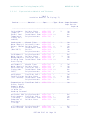
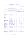


![1127117 - [PROJECT.TOC] - Performance Heating & Plumbing](http://vs1.manualzilla.com/store/data/005895106_1-55e9d6c83dbc31a8ba61d6bb401245cf-150x150.png)