1
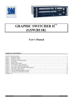
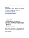
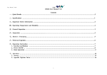
Peristaltic Pump
‘1200‘ Series
User’s Manual
Model ‘1201’ Peristaltic Pump
Model ‘1203’ Peristaltic Pump
Model ‘1210’ Peristaltic Pump
Model ‘1210A’ Peristaltic Pump
Model ‘1215’ Peristaltic Pump
Model ‘1215A’ Peristaltic Pump
55-xxxx
55-1762
55-1788
55-1796
55-1804
55-1812
WEEE/RoHS Compliance Statement
EU Directives WEEE and RoHS
To Our Valued Customers:
We are committed to being a good corporate citizen. As part of that commitment,
we strive to maintain an environmentally conscious manufacturing operation. The
European Union (EU) has enacted two Directives, the first on product recycling
(Waste Electrical and Electronic Equipment, WEEE) and the second limiting the use
of certain substances (Restriction on the use of Hazardous Substances, RoHS).
Over time, these Directives will be implemented in the national laws of each EU
Member State.
Once the final national regulations have been put into place, recycling will be offered
for our products which are within the scope of the WEEE Directive. Products falling
under the scope of the WEEE Directive available for sale after August 13, 2005 will
be identified with a “wheelie bin” symbol.
Two Categories of products covered by the WEEE Directive are currently exempt
from the RoHS Directive – Category 8, medical devices (with the exception of
implanted or infected products) and Category 9, monitoring and control instruments.
Most of our products fall into either Category 8 or 9 and are currently exempt from
the RoHS Directive. We will continue to monitor the application of the RoHS
Directive to its products and will comply with any changes as they apply.
• Do Not Dispose Product with
Municipal Waste.
• Special Collection/Disposal Required.
Table of Contents
H a r v a r d A p p a r a t u s P e r i s t a l t i c P u m p ‘1 2 0 0’ S e r i e s
1
SUBJECT
PAGE
Table of Contents ....................................................1
General Information - Warranty and Repairs ..........2
Specifications ..........................................................3
Model 1201 & 1203 Peristaltic Pumps ....................4
Model 600 Multi-Speed Transmission......................5
Model 1210 & 1215 Peristaltic Pumps ....................6
Multiple Tube Adapter ..............................................7
Silastic Tubing Information....................................8-9
Tubing and Flow Rate............................................10
Warranty and Repair Information
2
H a r v a r d A p p a r a t u s P e r i s t a l t i c P u m p ‘1 2 0 0’ S e r i e s
Serial Numbers
All inquires concerning our product should refer to the serial number of the unit.
Serial numbers are located on the rear of the chassis.
Calibrations
All electrical apparatus is calibrated at rated voltage and frequency.While the flow will
stay calibrated, the peak will vary.
Warranty
Harvard Apparatus warranties this instrument for a period of two yeara from date of
purchase.At its option, Harvard Apparatus will repair or replace the unit if it is found
to be defective as to workmanship or material.
This warranty does not extend to damage resulting from misuse, neglect or abuse, normal wear and tear, or accident.
This warranty extends only to the original customer purchaser.
IN NO EVENT SHALL HARVARD APPARATUS BE LIABLE FOR INCIDENTAL OR
CONSEQUENTIAL DAMAGES. Some states do not allow exclusion or limitation of
incidental or consequential damages so the above limitation or exclusion may not
apply to you. THERE ARE NO IMPLIED WARRANTIES OF MERCHANTABILITY,
OR FITNESS FOR A PARTICULAR USE, OR OF ANY OTHER NATURE. Some states
do not allow this limitation on an implied warranty, so the above limitation may not
apply to you.
If a defect arises within the two-year warranty period, promptly contact Harvard
Apparatus, Inc. 84 October Hill Road, Building 7, Holliston, Massachusetts 01746-1371
using our toll free number 1-800-272-2775. Goods will not be accepted for return
unless an RMA (returned materials authorization) number has been issued by our customer service department. The customer is responsible for shipping charges. Please
allow a reasonable period of time for completion of repairs, replacement and return.
If the unit is replaced, the replacement unit is covered only for the remainder of the
original warranty period dating from the purchase of the original device.
This warranty gives you specific rights, and you may also have other rights which vary
from state to state.
Repair Facilities and Parts
Harvard Apparatus stocks replacement and repair parts. When ordering, please
describe parts as completely as possible, preferably using our part numbers. If practical, enclose a sample or drawing.We offer a complete reconditioning service.
CAUTION
This pump is not registered with the FDA and is not for clinical use on human patients.
Specifications
H a r v a r d A p p a r a t u s P e r i s t a l t i c P u m p ‘1 2 0 0’ S e r i e s
3
Specifications
Model 1203
Catalog No.
Dimensions, H x W x D
Weight
Power
55-1762
250 x 265 x 280 mm (10 x 10-1/2 x 11 in)
11.4 kg (25 lb)
115/230 VAC, 50/60 Hz
Model 1210
Catalog No.
Dimensions, H x W x D
Weight
Power
55-1788
178 x 381 x 265 mm (7 x 15 x 10-1/2 in)
16.8 kg (37 lb)
115 VAC, 60 Hz, 2 Amp
Model 1210A
Catalog No.
Dimensions, H x W x D
Weight
Power
55-1796
178 x 381 x 265 mm (7 x 15 x 10-1/2 in)
16.8 kg (37 lb)
230 VAC, 50 Hz, 2 Amp
Model 1215
Catalog No.
Dimensions, H x W x D
Weight
Power
55-1804
178 x 381 x 267 mm (7 x 15 x 10-1/2 in)
22 kg (48 lb)
115 VAC, 60 Hz, 1 Amp
Model 1215A
Catalog No.
Dimensions, H x W x D
Weight
Power
55-1812
178 x 381 x 267 mm (7 x 15 x 10-1/2 in)
22 kg (48 lb)
230 VAC, 50 Hz, 1 Amp
Model 1201 & 1203
4
H a r v a r d A p p a r a t u s P e r i s t a l t i c P u m p ‘1 2 0 0’ S e r i e s
Description
Models #1201 and #1203 are peristaltic pumps designed for the transfer of liquids by
peristaltic action on the outside of rubber or plastic tubing. The pump is composed
of a #1200 Basic Pump Mechanism coupled to a heavy duty #600 multi-speed transmission.
Model 1201 is furnished with a synchronous motor that provides twelve accurate
pump rates.
Model 1203 is furnished with an electronically variable DC motor that provides a continuous range of speeds. Each of the twelve standard speeds is made continuously variable by the SCR motor speed control circuitry (labeled knob on side reading “% of
Indicated Rate”). Model 1203 is also furnished with a capped connector on the side.
Only the Model 551 Pump Speed Modulator can be used here (see pages 10-11 for
Model 551 data). The 1203 can be operated remotely or in response to the Pump
Speed Modulator.
The pumping mechanism consists of an aluminum housing containing a central shaft
upon which are mounted 13 eccentric cams each 30° apart. Thirteen cam followers
fit over the cams, translating the rotating motion into a reciprocal motion. Nylon
sheets above and below the cam followers provide a low friction bearing surface.
Parallel to the cam shafts are located the two compression plates used to squeeze the
tubing. A calibrated dial is provided so that a given compression can be reproduced.
The driving mechanism is a twelve position gear box driven by an 1800 rpm motor.
Output speed in position #1 is 60 rpm. A timing belt connects the output of the gear
box to the pump with no speed change. The built-in overload clutch is designed to
slip when the pump is overloaded.
Operation
Unless otherwise specified on the product label, the 1201 pump operates at 110-125
volt 60 cycle, and the 1203 pump operates at 110-125 volt 50-60 cycle. Frequency differences exist because of the different types of motors used. To operate the pump,
insert a piece of rubber or plastic between the cam followers and the pressure plate.
Moderately tighten the black calibrated pressure plate knob until the tubing is occluded. DO NOT OVER-TIGHTEN. The knurled thumbscrew directly over the black knob
is used to lock the pressure plate knob in place. The two thumbscrews on either side
of the black knob operate the clamp to hold the tubing in position. In general, it is
preferable to use the smallest practical tubing at the highest speed rather than large
tubing at slow rates. Since the two sides of the pump are 130° out of phase, it is possible to balance out the pulsatile flow characteristics by using two tubes in parallel,
joined by a “Y” connector.
Maintenance
Yearly lubrication of the gear box with a light machine oil is suggested but not mandatory. The gear box is available for lubrication by removing the four socket head screws
on the front panel. The peristaltic pump head requires no maintenance.
General Care
These pumps are designed for long-term durability. To insure long life of the pump,
carefully follow directions for speed changing as outlined in the “Model 600 MultiSpeed Transmission” section on the next page.
Model 600 Multi-Speed Transmission
5
H a r v a r d A p p a r a t u s P e r i s t a l t i c P u m p ‘1 2 0 0’ S e r i e s
Description
Unless otherwise noted, all units are for 110-120 AC, 60 cycle operation. The #600
Multi-Speed Transmission is a standardized, motorized gear reduction assembly complete with panel, motor, switch, cord, pilot light and output coupling. It is designed to
be used with a number of associated instruments and in special applications. The unit
is designed around a variety of reversible direct current and synchronous motors. The
transmission consists of a gear train designed to provide 12 steps of reduction. The
gears are always in motion and a selector gear actuated by the shift knob is used to
pick off any of 12 speeds. The reduction per step and speeds are as follows:
Position “:” is a neutral position meaning that the output shaft is disconnected from
the gearing.
Knob
Position
Reduction
1800 RPM
Sec/Rev.
1
1
1
2
.4
2.5
3
.2
5
4
.1
10
5
.05
20
6
.02
50
7
.01
100
8
.005
200
9
.002
500
10
.001
1000
11
.0005
2000
12
.0002
5000
Operation
To change speeds, the shift knob must be pulled out and turned to the desired position where it then can be released. The selector gear disengaged when the selector
knob is pulled out against the spring. DO NOT ATTEMPT TO CHANGE SPEEDS
WITHOUT FIRST PULLING OUT THE SELECTOR KNOB. While all the gears can
be shifted when the motor is running, it is recommended that the motor be shut off
when shifting in Positions 1, 2 and 3. As is typical of all gear trains with large reductions, it sometimes may require a short delay before the slowest gears are in a position
to mesh.
Lubrication
A light machine oil or grease is recommended for the gears. For motor lubrication, see
the motor manufacturer’s card.
Model 1210 & 1215 Peristaltic Pumps
6
H a r v a r d A p p a r a t u s P e r i s t a l t i c P u m p ‘1 2 0 0’ S e r i e s
Description
Models 1210 and 1215 are peristaltic pumps designed for the transfer of liquids or slurries by peristaltic action on the outside of rubber or plastic tubing. The pump is composed of a #1200 Basic Pump Mechanism coupled to a shunt wound DC motor. A silicon control rectifier system, with a feed-back circuit is used to control the motor
speed.
Models #1210 and #1215 are furnished with a capped-connector on the front panel.
Only the Model 551 Pump Speed Modulator can be used here (see pages 10-11 for
Model 551 data). The two modules can be operated remotely or in response to the
Pump Speed Modulator.
The pumping mechanism consists of an aluminum housing containing a central shaft
upon which are mounted 13 cams, each 30° apart. Thirteen cam followers fit over the
cams, translating the rotating motion into a reciprocal motion. Nylon sheets above and
below the cam followers provide a low friction bearing surface. Parallel to the cam
shafts are located the two compression plates used to occlude the tubing. A calibrated dial is provided so that a given compression can be reproduced.
Operation
Unless otherwise specified on the product label, these pump operate at 110-125 volt
50-60 cycle. To operate the pump, insert a piece of rubber or plastic between the cam
followers and the pressure plate. Moderately tighten the black calibrated pressure
plate knob until the tubing is occluded. DO NOT OVER-TIGHTEN. The knurled
thumbscrew directly over the black knob is used to lock the pressure plate knob in
place. The two thumbscrews on either side of the black knob operate the clamp to
hold the tubing in position.
In general, it is preferable to use the smallest practical tubing at the highest speed
rather than large tubing at slow rates. Since the two sides of the pump are 180° out
of phase, it is possible to balance out the pulsatile flow characteristics by using two
tubes in parallel, joined by a “Y” connector. For more efficient reduction of pulses, a
trapped air buffer chamber can be set up.
Maintenance
The pump mechanism should require no major maintenance. Normal care and cleaning will ensure proper function. To maintain the motor, remove the front or rear panels to expose the motor, and follow manufacturer’s instructions. Tampering with the
motor is not recommended. Service should be performed by a qualified technician.
Multiple Tube Adapter
7
H a r v a r d A p p a r a t u s P e r i s t a l t i c P u m p ‘1 2 0 0’ S e r i e s
Installation Instructions
The 1220 Multiple Tube Adapter can be assembled to any 1200 Series Peristaltic Pump
without altering the pump mechanism. This adapter allows for the use of three 1/4"
ID by 1/16" wall tubes, five 1/8" ID by 1/16" wall tubes, or ten 1/16" ID by 1/32" wall
tubes. A 1-1/4" adjustable space slot provides vertical alignment for the inserted tubing. Refer to the instructions listed below and the diagram on the following page for
the correct assembly procedure.
1. Remove existing 4 screws from the middle section of the #1200 Pump
Mechanism and assemble stamped plate (1200-005) over cover. Replace
screws.
2. Remove the 2 end cover plates and large thumb screws from pump (discard
end cover plates). Attach bracket with thumb screws (1220-002) and slide
plate (1220-004) over. Use existing hardware and reassemble. Replace large
thumb screw.
Silastic Tubing Information
H a r v a r d A p p a r a t u s P e r i s t a l t i c P u m p ‘1 2 0 0’ S e r i e s
8
Silastic brand medical-grade tubing is an inert tubing for surgical and pharmaceutical
use. It is unaffected by prolonged shelf storage, exhibits high flexural durability, and
may be sterilized repeatedly without deterioration. Its compatibility with body tissues
and fluids permits long-term implantation, and its adhesive character resists incrustation and clogging, thereby improving flow characteristics. Silastic tubing will not support bacterial or fungal growth.
Foreign body reactions can be evoked by surface contaminants such as dust, tald, skin
oil deposited during handling, etc. Extreme care mus be taken to prevent such contamination after cleaning and sterilization.
To Clean
Wash thoroughly in a hot water-soap solution to remove sodium bicarbonate (dusted
on surface to facilitate handling) and other possible surface contaminants.
Use a non-oily mild soap,
such as Ivory Flakes.
Do Not use synthetic detergents
or oil-based soaps.
Rinse copiously in hot water and follow with a thorough rinse in distilled water. Flush
the lumen of the tubing thoroughly to insure the removal of all traces of soap.
To Sterilize
Wet the tubing lumen just prior to autoclaving. Wrap the tubing in lint-free cloth or
place in a clean, open tray.
Autoclave by one of the following methods:
1. High speed instrument (flash) sterilizer - 10 minutes at 270°F (30 psi)
2. Standard gravity sterilizer - 30 minutes at 250°F (15 psi)
3. Prevacuum high temperature sterilizer - normal cycle (30-35 minutes) at
250°F
Silastic medical-grade tubing is heat stable up to 500°F and retains its physical properties such as tensile strength, elasticity, and other elastometric characteristics under
repeated sterilizations. Ethylene oxide sterilization is not recommended because it is
difficult to determine when gas emission is complete.
Silastic Tubing Information
9
H a r v a r d A p p a r a t u s P e r i s t a l t i c P u m p ‘1 2 0 0’ S e r i e s
Applications
Clinically reported applications of Silastic brand medical-grade tubing include arterial
venous shunts, perfusion tubing for open heart surgery, permanent ureteral prosthesis, intravenous and intra-arterial catheters, intestinal decompression tubes, blood
transfusion and parenteral solutions administration tubing, and lacrimal drainage
tubes. In published animal test evaluations, favorable results have been reported using
Silastic medical-grade tubing for abdominal drains and ureteral prostheses.
Caution
If tubing is cut or nicked, the damaged portion should be removed; cuts can reduce
tubing tear strength.
Note:
Tubing is not sterile upon delivery.
Follow the above directions carefully for
cleaning and sterilization.
Availability
Silastic tubing is available in 1/8" and 1/4" inner diameters x 1/16" wall thickness
directly from Harvard Apparatus Company (#2325P and #2327P, respectively) in 50
feet lengths. Tubing is also available from Dow-Corning Corporation in Midland,
Michigan.
Tubing & Flow Rates
H a r v a r d A p p a r a t u s P e r i s t a l t i c P u m p ‘1 2 0 0’ S e r i e s
10
Model 1203 Peristaltic Pump
Silastic Tubing, 7.7 m (25 ft) Coils
Tubing ID x OD
Flow Rate
Minimum
Maximum
Catalog
Number
1/16 x 3/16 inches
0.000133 ml/min
6.8 ml/min
56-4850
1/8 x 1/4 inches
0.00042 ml/min
21 ml/min
56-4849
3/16 x 5/16 inches
0.0008 ml/min
39 ml/min
56-4831
1/4 x 3/8 inches
0.0012 ml/min
60 ml/min
56-4823
5/16 x 7/16 inches
0.0017 ml/min
84 ml/min
56-4815
3/8 x 1/2 inches
0.002 ml/min
114 ml/min
56-4807
Model 1210 & 1210A Peristaltic Pump
Silastic Tubing, 7.7 m (25 ft) Coils
Tubing ID x OD
Flow Rate
Minimum
Maximum
Catalog
Number
1/16 x 3/16 in
1.2 ml/min
20 ml/min
56-4850
1/8 x 1/4 in
3.5 ml/min
70 ml/min
56-4849
3/16 x 3/16 in
6.5 ml/min
130 ml/min
56-4831
1/4 x 3/8 in
10 ml/min
200 ml/min
56-4823
5/16 x 7/16 in
14 ml/min
280 ml/min
56-4815
3/8 x 1/2 in
19 ml/min
380 ml/min
56-4807
Model 1215 & 1215A Peristaltic Pump
Silastic Tubing, 7.7 m (25 ft) Coils
Tubing ID x OD
Flow Rate
Minimum
Maximum
Catalog
Number
1/16 x 3/16 in
3.3 ml/min
70 ml/min
56-4850
1/8 x 1/4 in
10.5 ml/min
210 ml/min
56-4849
3/16 x 3/16 in
18.5 ml/min
390 ml/min
56-4831
1/4 x 3/8 in
310 ml/min
600 ml/min
56-4823
5/16 x 7/16 in
42 ml/min
840 ml/min
56-4815
3/8 x 1/2 in
57 ml/min
1140 ml/min
56-4807