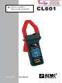
1
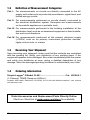
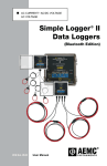
SIMPLE LOGGER® II TRMS CLAMP-ON MODEL ENGLISH User Manual CL601 Statement of Compliance Chauvin Arnoux®, Inc. d.b.a. AEMC® Instruments certifies that this instrument has been calibrated using standards and instruments traceable to international standards. We guarantee that at the time of shipping your instrument has met its published specifications. An NIST traceable certificate may be requested at the time of purchase, or obtained by returning the instrument to our repair and calibration facility, for a nominal charge. The recommended calibration interval for this instrument is 12 months and begins on the date of receipt by the customer. For recalibration, please use our calibration services. Refer to our repair and calibration section at www.aemc.com. Serial #: _ ________________________________ Catalog #: 2126.01 Model #: CL601 Please fill in the appropriate date as indicated: Date Received: __________________________________ Date Calibration Due: ________________________ Chauvin Arnoux®, Inc. d.b.a AEMC® Instruments www.aemc.com Table of Contents 1. INTRODUCTION................................................................................ 3 1.1 1.2 1.3 1.4 International Electrical Symbols.................................................3 Definition of Measurement Categories......................................4 Receiving Your Shipment...........................................................4 Ordering Information..................................................................4 2. PRODUCT FEATURES....................................................................... 5 2.1 Description.................................................................................5 2.2 Control Features........................................................................6 3. SPECIFICATIONS............................................................................. 8 3.1 3.2 3.3 3.4 Electrical....................................................................................8 Mechanical.................................................................................9 Environmental............................................................................9 Safety.........................................................................................9 4. OPERATION................................................................................... 10 4.1 4.2 4.3 4.4 LED Control Operation and Status Function...........................10 Connecting the Simple Logger® II to a Computer....................12 Turning the Unit On.................................................................12 Recording Data........................................................................13 4.4.1 Starting a Recording Session......................................13 4.4.2 Stopping a Recording Session....................................13 4.5 Downloading Recorded Data...................................................13 4.6 Clearing Alarm Indication.........................................................14 4.7 Erasing Data from Memory......................................................14 4.8 Data Storage............................................................................15 4.8.1 Trend Measurements...................................................15 4.9 Normal Operation....................................................................15 4.10 Reset Switch Operation...........................................................18 5. MAINTENANCE.............................................................................. 19 5.1 Changing the Batteries............................................................19 APPENDIX A: TROUBLESHOOTING....................................................... 20 APPENDIX B: GLOSSARY..................................................................... 21 Repair and Calibration............................................................................22 Technical and Sales Assistance.............................................................22 Limited Warranty....................................................................................23 Warranty Repairs....................................................................................23 CHAPTER 1 INTRODUCTION WARNING These safety warnings are provided to ensure the safety of personnel and proper operation of the instrument. • Read the instruction manual completely and follow all the safety information before attempting to use or service this instrument. • Never exceed the maximum working voltage ratings given. • NEVER open the back of the instrument while connected to any circuit or input. • Always inspect the instrument accessories and leads prior to use. Replace any defective parts immediately with factory parts. 1.1 International Electrical Symbols Signifies that the instrument is protected by double or reinforced insulation. Indicates a WARNING and that the operator must refer to the user manual for instructions before operating the instrument. Failure to follow or carry out any instructions preceded by this symbol in the user manual may result in personnel injury or damage to the instrument and installations. Risk of electric shock. The voltage at parts marked with this symbol may be dangerous. Refers to a type A current sensor. This symbol signifies that application around and removal from HAZARDOUS LIVE conductors is permitted. Refers to a type B current sensor. Do not apply around or remove from HAZARDOUS LIVE conductors without additional protective means (de-energizing the circuit or wearing protective clothing suitable for high voltage work). In conformity with WEEE 2002/96/EC Simple Logger® II Model CL601 3 1.2 Definition of Measurement Categories Cat. I: For measurements on circuits not directly connected to the AC supply wall outlet such as protected secondaries, signal level, and limited energy circuits Cat. II: For measurements performed on circuits directly connected to the electrical distribution system. Examples are measurements on household appliances or portable tools. Cat. III:For measurements performed in the building installation at the distribution level such as on hardwired equipment in fixed installation and circuit breakers. Cat. IV:For measurements performed at the primary electrical supply (<1000V) such as on primary overcurrent protection devices, ripple control units, or meters 1.3 Receiving Your Shipment Upon receiving your shipment, make sure that the contents are consistent with the packing list. Notify your distributor of any missing items. If the equipment appears to be damaged, file a claim immediately with the carrier and notify your distributor at once, giving a detailed description of any damage. Save the damaged packing container to substantiate your claim. 1.4 Ordering Information Simple Logger® II Model CL601....................................... Cat. #2126.01 (1-Channel, TRMS Clamp-on 600AAC) Includes USB cable, DataView® CD-ROM, 2x1.5V AA-cell alkaline batteries, user manual and warranty card. Order Accessories and Replacement Parts Directly Online Check our Storefront at www.aemc.com/store for availability 4 Simple Logger® II Model CL601 CHAPTER 2 PRODUCT FEATURES 2.1 Description The Simple Logger® II Model CL601 is a battery powered, one channel recording device with an alkaline battery pack. Line tracking is performed such that 64 samples over one line cycle are taken. Frequency tracking is performed over the range of ±2Hz around the nominal line frequency (50 or 60Hz). Harmonic measurements are calculated from these 64 samples (Harmonics are only available from the Simple Logger® II Control Panel within the DataView® application). The Simple Logger® II records TRMS at a rate of up to eight times per second. The measurement process is performed no more than eight times per second. TRMS calculations are performed on a single line cycle. This means that the input(s) are ignored between measurement intervals. The main advantage of the logger is its ability to perform a variety of recording tasks with easy and intuitive setup from a computer using DataView® software. Analog information on the input is sampled and converted to a digital signal. This digital signal is processed and stored along with scale and time information. An optically isolated Universal Serial Bus (USB) port provides for the transfer of data from the instrument’s internal memory to the computer for analysis. Simple Logger® II Model CL601 5 2.2 Control Features 1 2 3 Figure 2-1. Key Components and Features 1. Control Button (PRESS) This button marked “PRESS” selects the mode of operation. Use this button to start or stop recordings, erase the memory, clear alarms and turn the instrument ON/OFF. 6 Simple Logger® II Model CL601 2. Five LED Indicators The LEDs on the instrument serve two functions: control operation and status function. • The control operation (function when holding down the PRESS button) is indicated with text to the left of each LED. • The status function (function when PRESS is not being held down) associated with each LED is indicated with text to the right of each LED. • Refer to § 4.1 for detailed descriptions of each LED. 3. Female Type Mini-B USB Connector 4. Reset Button (not shown) The RESET button resets the CPU and is located in the battery compartment To access this button, remove the battery compartment cover, then reset the instrument by inserting a small tool (such as a paper clip) through the hole in the case to activate it. 5. Flash Upgrade Switches (not shown) These two switches (accessible from under the battery compartment), along with the RESET button (and PC software), are used to recover from a failed flash upgrade procedure. WARNING: If the RESET button is pressed when the logger is recording, it will stop recording and data in memory may be lost. Simple Logger® II Model CL601 7 CHAPTER 3 SPECIFICATIONS 3.1 Electrical Reference Conditions: 23°C ± 3°C, 30-50% RH, DC or 50/60 Hz, no AC external magnetic field, DC magnetic field ≤ 40A/m, centered conductor, battery voltage: 3V ± 10%. MODEL Channels Input Current Range CL601 One Split CT – AC Current 0 to 600AAC Resolution 0.1A Accuracy (50/60Hz) 0 to 5A: Unspecified 5 to 50A: ±(1% of Reading +1A) 50 to 400A: ±(1% of Reading +0.5A) 400 to 600A for duration <10min: ±(3% of Reading +1A) Sample Rate Storage Rate 64 samples/cycle Programmable from 125mS to 1 day Storage Modes Start/Stop, FIFO and Extended Recording Mode* (XRM™) Recording Length 15 minutes to 8 weeks, programmable using DataView® Memory Communication Communication Rate Power Source** Battery Life 240,000 measurement (512KB) The recorded data is stored in non-volatile memory and will be retained even if the battery is low or removed. USB 2.0 optically isolated 115200 bps 2x1.5V AA-cell alkaline batteries 100 hours to > 45 days (dependent on sample rate and recording length) *This unique recording mode provides the opportunity to continuously record over long periods of time by reducing the stored sample resolution of the oldest data and maintaining matching resolution for the newest data. Each time the memory fills up using XRM™, every other of the oldest stored samples is discarded making room for newer samples. This process continues until the recording is manually stopped. **A memory backup capacitor provides backup power while the batteries are being changed. This backup capacitor will maintain the instrument for up to 10 seconds without batteries installed. After 10 seconds the date, time and configuration will need to be reset (no data will be lost). If the unit is connected to DataView® via a PC, the battery life is 100 hours regardless of the storage rate. 8 Simple Logger® II Model CL601 3.2 Mechanical Dimensions: 9.25 x 4.0 x 1.63" (235 x 102 x 41mm) Weight (with battery): 1.07 lbs (17.1 oz) Case: Polycarbonate UL94-V0 Maximum Conductor Size: 1 conductor - Ø 1.65" (42 mm) 2 conductor - Ø 1.00" (25.4 mm) each Jaw Opening: 1.65" (42mm) max Vibration: IEC 68-2-6 (1.5mm 10 to 55Hz) Shock: IEC 68-2-27 (30G) Drop: IEC 68-2-32 (1m) 3.3 Environmental Operating Temperature: 14° to 122°F (-10° to 50°C) Storage Temperature: -4° to 140°F (-20° to 60°C) Relative Humidity: 0 to 85% @ 95°F (35°C), Non-condensing Altitude: 2000m 3.4 Safety 600V Cat. III 300V Cat. IV *All specifications are subject to change without notice Simple Logger® II Model CL601 9 CHAPTER 4 OPERATION 4.1 LED Control Operation and Status Function The ON/OFF state of the instrument can be determined by pressing the PRESS button for less than 0.5 seconds. If the instrument is ON, the status of the instrument will be shown by the LEDs. If the instrument is OFF no indication will be given (the LEDs will not blink). The instrument is turned ON by pressing the PRESS button until all LEDs light. At this point, the button can be released and the instrument will remain in the ON state. If the button is released before all the LEDs light (in unison), the instrument will remain in the OFF state. When holding the PRESS button while the instrument is ON, each LED will light in sequence. If the LEDs light in sequence, continue to hold the PRESS button until the last LED lights and then goes OFF. At this point, releasing the button will result in no action being taken. This provides a mechanism to cancel (or ignore) the button press. Control of the instrument is performed by pressing and holding the PRESS button (while the instrument is ON) until the control LED corresponding to the desired operation lights. Releasing the button when the desired control LED is illuminated results in the corresponding operation being performed. Turning the instrument OFF (pressing and holding the PRESS button until the Blue LED lights), will not terminate an active recording or prevent a scheduled recording from starting. While the instrument is OFF, it will momentarily turn ON for each scheduled sample interval. This operation will make sure that a scheduled recording will begin and sample intervals will be stored even while the instrument is OFF. The control operation of each LED is as follows: 10 • GREEN: Starts a recording • ORANGE: Stops a recording • YELLOW: Clears the alarm state • RED: Erases the memory • BLUE: Turns the instrument OFF Simple Logger® II Model CL601 The status function of each LED is as follows: GREEN LED OFF LED Single-blink LED Double-blink STATUS Logger is turned OFF or in Low Power Standby state* Logger is in Standby Mode (and not recording) Logger is in Record Mode ORANGE LED OFF LED Single-blink STATUS Logger is not in an Overload condition One or more inputs are in an Overload condition YELLOW LED OFF LED Single-blink LED Double-blink STATUS No alarm has been seen on any input At least one channel has seen an alarm at least once At least one channel is currently in an alarm condition RED LED OFF LED Single-blink LED Double-blink STATUS No data in memory Memory is partially filled Memory is full BLUE LED OFF LED Single-blink STATUS Battery voltage is above 1.8 volts Battery voltage is below 1.8 volts *To determine whether the unit is OFF or in SLEEP mode, press the PRESS button for 0.5 seconds. If all LEDs light, the logger is not OFF. Note: Overload occurs when any input is 10% above its input range. When the battery voltage goes below 1.7 volts the instrument will shut down (terminating the recording, if it is recording). In the SLEEP and OFF modes, the logger retains recorded information for transfer to a computer. Both of these modes have low power states, which require very little power from the battery. The LEDs will not blink at this time. By using these low power states, the instrument can be programmed to start recording at some time in the future without draining the batteries. • SLEEP mode: The instrument enters the low power state if the button is not pressed for one minute. It will remain in this state until either the button is pressed or the internal clock reaches the start time for a scheduled recording. • RECORD mode: The instrument enters the low power state between sample sets. The slower the storage rate, the greater the portion of time the instrument is in the low power state. Thus, the slower the storage rate, the longer the instrument can record. Simple Logger® II Model CL601 11 4.2 Connecting the Simple Logger® II to a Computer INSTALL DATAVIEW® BEFORE CONNECTING TO THE COMPUTER. Connect the Simple Logger® II to a USB communication port on your computer. Refer to the computer manual to locate the USB port on your computer. The logger can be connected to the computer during a recording session, however, additional battery drainage will occur to support the active USB connection. 4.3 Turning the Unit On Turn the instrument ON by performing one of the following: • Press and hold the PRESS button for approximately 2 seconds. Release the button after all five LEDs light up in unison. The unit is now in the STANDBY mode (Green LED single-blinks). NOTE: If all LEDs light instantaneously, the instrument was in SLEEP mode. Releasing the PRESS button will show the status. • Connect the instrument to a USB port on your computer and establish communication with the instrument using DataView®. The logger will remain ON while a communication link with the SLII Control Panel is active (provided sufficient battery power is available during the communication session). The instrument contains protection circuitry to prevent it from being turned on when the battery voltage is below 1.7V. There are two thresholds for the battery voltage: • The first is used to indicate low battery. The low battery indicator will blink when the battery voltage drops below 1.8V. • The second is used to determine when to terminate recording and turn the unit off. The shutdown threshold is when the battery voltage drops below 1.7V. 12 Simple Logger® II Model CL601 4.4 Recording Data NOTE: The Simple Logger® II is factory configured and may be altered to fit the users needs (see the Configuring the Simple Logger® II section inside the DataView® user manual). Once a configuration is written to the instrument, the logger will no longer need to be connected to DataView® to start the configured recording. When data is stored in the memory, the user may download the information onto a hard-disk (see the Downloading Recorded Instrument Data section inside the DataView® user manual). 4.4.1 Starting a Recording Session NOTE: A new recording cannot be started if the memory is full. 1. Connect the instrument to the measurement source. 2. Make sure the logger is in STANDBY mode (see § 4.3). 3. Press and hold the PRESS button. When the START (GREEN) LED lights up, release the button. 4. The GREEN LED double-blinks when the logger is recording. 4.4.2 Stopping a Recording Session 1. Press and hold the PRESS button. When the STOP (ORANGE) LED lights up, release the button. 2. The GREEN LED will change from a double-blink to a single-blink, indicating STANDBY mode. The data will be retained, even if the instrument is turned OFF. The recorded data is stored in Flash memory (maintained even in the absence of batteries). The recorded data may be downloaded to a computer. 4.5 Downloading Recorded Data Recorded measurements stored in the instrument are transferred to a computer via the download command in the SLII Control Panel. For instructions on downloading data, see the Downloading Recorded Instrument Data section inside the DataView® manual. Simple Logger® II Model CL601 13 4.6 Clearing Alarm Indication Clearing alarms can be performed in the STANDBY or RECORD mode. 1. Press and hold the PRESS button. When the ALARM (YELLOW) LED lights up, release the button. The YELLOW LED will blink at a fast rate for a period of five seconds. 2. Press the PRESS button for another 0.5 seconds to complete the operation. NOTE: This does not clear any stored alarms, only indications. Stored alarms can only be cleared when memory is erased (see § 4.7). 4.7 Erasing Data from Memory Erasing data from the instrument’s memory can only be performed while in the STANDBY mode. There are two ways to erase the memory: Erasing the Memory using the PRESS Button: 1. Press and hold the PRESS button. When the ERASE (RED) LED lights up, release the button. This will arm the instrument for an erase operation (when not in record mode). While armed to erase memory, the RED LED will blink at a fast rate for a period of five seconds. 2. Press the PRESS button for another 0.5 seconds to complete the erase operation. NOTE: If the button is not pressed within five seconds of arming, the erase operation will automatically disarm and memory will be maintained. For this reason, if you do not intend to erase memory, simply wait until the RED LED stops blinking at the fast rate. Erasing the Memory using the SLII Control Panel: 1. Connect the instrument to the computer, then open the SLII Control Panel. 2. Select Erase Memory from the Instrument Menu. 14 Simple Logger® II Model CL601 3. A dialog box will appear asking to confirm the erasure of instrument memory. Select Yes to confirm or No to cancel the operation. NOTE: Clearing the memory will also clear any alarms stored. 4.8 Data Storage The logger captures Trend measurements. Input Channel: Source for the measurement channel of the instrument. Measurement Channel: Measurement of input. This can be a simple direct measurement, the result of complex mathematical operations on a single or multiple input, or other channels. Sample Rate: The rate at which the instrument measures inputs. Storage Rate: The rate at which channel measurements are stored. 4.8.1 Trend Measurements The logger stores the TRMS calculation of each of the inputs. In addition, the user can define the storage rate, recording period and measurement format using the Configure Instrument dialog box in the SLII Control Panel software. Trend measurements are stored at this fixed storage rate. 4.9 Normal Operation When the instrument is turned ON, the following occurs (provided there is sufficient battery voltage and no data is stored in the instrument’s memory): • The GREEN LED single-blinks. (STANDBY mode is active and the logger is not recording). • The RED LED is OFF, indicating there is no data in memory. • The PRESS button is used to Start and Stop a Recording Session. • If the PRESS button is not pressed for a period of one minute, the instrument will enter SLEEP mode and wait for either another button press or the recording start time to arrive (if a recording is scheduled). While in SLEEP mode, the LEDs will not blink. • A button press of 0.5 seconds will return the unit back to the normal STANDBY mode. Simple Logger® II Model CL601 15 Event: Recording with Memory Cleared When a recording starts, the logger will continue to record until one of the following occurs: • The Session is complete. • The Memory is full and the recording mode is Start/Stop. • The PRESS button is pushed until the STOP (ORANGE) LED lights up and is released before the next LED lights. • The Stop Recording command from the SLII Control Panel is sent to the unit. • The battery voltage falls below 1.7V. Event: Recording with a Partial or Full Memory If the RED LED is double-blinking, the memory must be cleared before any further recording can be performed. If the RED LED is single-blinking prior to starting a New Recording Session, the memory is partially full. To save, clear or check memory availability, use the Simple Logger® II Control Panel software. There may be instances where the GREEN LED is also double-blinking indicating that the logger is still recording. The user can choose to stop the Recording Session and download the saved session(s) and/or erase the memory. NOTE: The logger memory cannot be erased while in the Record mode. The recording must be stopped first. Event: Memory Filled During Recording Session If the logger is recording using the Start/Stop mode and memory is filled before the Recording Session has finished, the session will end. The following happens: • The GREEN LED single-blinks. • The RED LED double-blinks. At this time: • • 16 The memory can be downloaded and erased. A new recording can be started or scheduled once the memory is erased. Simple Logger® II Model CL601 Event: Battery Power is Insufficient for a Full Recording Duration If the battery voltage drops below 1.7V, the following will occur: • • • The Recording Session will terminate. The Data will be saved. The GREEN and RED LED will turn OFF. The logger continues to record until the battery voltage drops below 1.7V. Pressing the PRESS button may not turn the unit ON at all. The battery voltage may rise slightly after the unit turns itself off. In this event, the unit may turn on momentarily as a result of a button press. The batteries must be replaced before the recorded session(s) can be downloaded from the instrument. NOTE: Replacing the batteries while the unit is OFF will not result in the loss of data memory. The internal backup capacitor will maintain the clock and memory while the main batteries are being replaced. If the battery level falls below the usable level or if the batteries have been removed for an extended period of time, the clock time will be lost. However, the recorded memory will be maintained since it is stored in Flash memory. Event: Recording Session has Ended The logger will be in STANDBY mode if one of the following occurs: • • • The session terminates due to recording end time being reached. The recording in START/STOP mode fills the memory. The user terminates the session by pressing the PRESS button until the STOP (ORANGE) LED lights up and releasing the button before the next LED lights, or issues a Stop Recording command from the Simple Logger® II Control Panel. Under these conditions, it is possible to turn the logger ON from the computer to download the data, if the batteries have sufficient power. The logger is now ready for a New Session or Download. Pressing the PRESS button until the START (GREEN) LED lights up and releasing the button before the next LED lights, will start a New Session depending on the available memory. Simple Logger® II Model CL601 17 4.10 Reset Switch Operation The RESET switch is located in the battery compartment. To access it, remove the battery compartment cover, then reset the instrument by inserting a small tool (such as a paper clip) through the hole in the case to activate it. NOTE: It is recommended to only press the RESET switch when the logger stops responding to a normal press button control when not connected to DataView®. It is not recommended to reset the instrument when the logger is recording, downloading or being configured. If the logger is not responding to a button press, make sure the unit has sufficient battery power. If the battery voltage is below 1.7V, the unit will not respond to a button press. In this condition, pressing the RESET switch will not restart the unit. It is recommended to download any desired session, then erase the memory before starting a new recording. 18 NOTE: The resumption of the logger operation in the above situations assumes that the RESET switch cleared the fault(s). The logger will not resume normal operation if the fault condition still exists. The instrument will try to recover normally. However, under certain conditions, the clock and memory full state may be reset. Simple Logger® II Model CL601 CHAPTER 5 MAINTENANCE Use only factory specified replacement parts. AEMC® will not be held responsible for any accident, incident, or malfunction following a repair done other than by its service center or by an approved repair center. 5.1 Changing the Batteries NOTE: It is recommended that all data is downloaded before replacing the batteries. WARNING: Turn the unit off before changing the batteries or loss of recorded data may occur. Disconnect the unit from any voltage measurement points before opening the rear cover to change the batteries. • Remove the screw from the battery cover • Slide off cover to remove • Replace with only 1.5V AA alkaline batteries, then replace cover • Press the PRESS button for 2 seconds to turn ON NOTE: If the instrument is stored without the batteries installed, the internal clock will need to be reset using the Simple Logger® II Control Panel software once the batteries are installed. Only store the unit with the batteries installed for short periods of time. For prolonged storage of the unit, it is recommended to remove the batteries. WARNING: Pressing the RESET button can result in the loss of recorded data. The instrument will try to recover normally, however under certain conditions, the clock may reset and the memory may fill. The clock may then need to be set and memory erased before another recording can start. The RESET button should only be pressed as a last resort. An additional memory backup capacitor is used to provide backup power while the main batteries are being changed. This backup power will last for approximately 10 seconds while batteries are not installed. Simple Logger® II Model CL601 19 APPENDIX A TROUBLESHOOTING Symptom: After being in a damp, cold environment, the logger does not function. Cause, Correction: Condensation may have formed inside the logger, shorting out the circuitry and discharging the battery. Allow the circuit board to dry thoroughly in a warm location. Symptom: The instrument does not start recording. Cause, Correction: Make sure battery power is present. Make sure the PRESS button is pushed long enough to light the GREEN LED and released before the next LED lights. Make sure the RED LED is not doubleblinking. If it is, memory is full and you need to erase the data (see § 4.7). Make sure the Simple Logger® II is properly configured so that you have Storage Rate, Recording Period and at least one Measurement Channel specified. Symptom: The instrument does not respond to a button press even with fresh batteries installed. Cause, Correction: Make sure that the instrument is not OFF. Press the button for a short duration (less than 0.5 seconds). If the LEDs do not flash, then the instrument is OFF. Turn the instrument ON by pressing the PRESS button for two seconds. The LEDs will light solid once the instrument has turned on and you may release the button at that time. Symptom: The instrument does not communicate; LED’s blink dimly at a fast rate. Cause, Correction: This is a fault condition that can be resolved by manually erasing the memory (refer to §4.7). 20 Simple Logger® II Model CL601 APPENDIX B GLOSSARY Some general terminology associated with the data collection process is listed here for convenience. Bps: Bits Per Second, a unit of signal transfer speed equal to the number of elements per second. The Simple Logger® II transfers data at the rate of 115200 bps. Button: An actual key on the logger or computer keyboard or a soft key in the program on the computer screen. Data logger: A device used to sample and store electrical signals representative of physical phenomena such as temperature, pressure and flow, for long periods of time in an unattended environment. Download: The process of transferring data from the logger to the computer. Hz: Hertz, a unit of measure of frequency equivalent to cycles per second. I/O: Input/output, a device or port capable of sending or receiving digital information. Port: A name given to any connector allowing input or output of information. Processor: A computing device used to calculate and run a set of instructions. Recording session: A recording session is defined as the time and data contained within the starting and ending of a recording. Resolution: The number of bits in which digitized values will be stored. The Simple Logger® II has 12-bit resolution. Ride-through: Time during which the AC line voltage has dropped sufficiently low to not be able to power the instrument. Zoom: The ability to select a section of the graph and magnify it for better readability. USB: Universal Serial Bus, a communications port used to access the Data Logger via a computer program (Dataview®). Simple Logger® II Model CL601 21 Repair and Calibration To ensure that your instrument meets factory specifications, we recommend that it be scheduled back to our factory Service Center at one-year intervals for recalibration, or as required by other standards or internal procedures. For instrument repair and calibration: You must contact our Service Center for a Customer Service Authorization Number (CSA#). This will ensure that when your instrument arrives, it will be tracked and processed promptly. Please write the CSA# on the outside of the shipping container. If the instrument is returned for calibration, we need to know if you want a standard calibration, or a calibration traceable to N.I.S.T. (Includes calibration certificate plus recorded calibration data). Ship To: Chauvin Arnoux®, Inc. d.b.a. AEMC® Instruments 15 Faraday Drive Dover, NH 03820 USA Phone:(800) 945-2362 (Ext. 360) (603) 749-6434 (Ext. 360) Fax: (603) 742-2346 or (603) 749-6309 E-mail:[email protected] (Or contact your authorized distributor) Costs for repair, standard calibration, and calibration traceable to N.I.S.T. are available. NOTE: You must obtain a CSA# before returning any instrument. Technical and Sales Assistance If you are experiencing any technical problems, or require any assistance with the proper operation or application of your instrument, please call, mail, fax or e-mail our technical support team: Chauvin Arnoux®, Inc. d.b.a. AEMC® Instruments 200 Foxborough Boulevard Foxborough, MA 02035 USA Phone:(800) 343-1391 (508) 698-2115 Fax: (508) 698-2118 E-mail:[email protected] www.aemc.com NOTE: Do not ship instruments to our Foxborough, MA address. 22 Simple Logger® II Model CL601 Limited Warranty The Simple Logger® II is warranted to the owner for a period of one year from the date of original purchase against defects in manufacture. This limited warranty is given by AEMC® Instruments, not by the distributor from whom it was purchased. This warranty is void if the unit has been tampered with, abused or if the defect is related to service not performed by AEMC® Instruments. For full and detailed warranty coverage, please read the Warranty Coverage Information, which is attached to the Warranty Registration Card (if enclosed) or is available at www.aemc.com. Please keep the Warranty Coverage Information with your records. What AEMC® Instruments will do: If a malfunction occurs within the one-year period, you may return the instrument to us for repair, provided we have your warranty registration information on file or a proof of purchase. AEMC® Instruments will, at its option, repair or replace the faulty material. REGISTER ONLINE AT: www.aemc.com Warranty Repairs What you must do to return an Instrument for Warranty Repair: First, request a Customer Service Authorization Number (CSA#) by phone or by fax from our Service Department (see address below), then return the instrument along with the signed CSA Form. Please write the CSA# on the outside of the shipping container. Return the instrument, postage or shipment pre-paid to: Ship To: Chauvin Arnoux®, Inc. d.b.a. AEMC® Instruments 15 Faraday Drive • Dover, NH 03820 USA Phone:(800) 945-2362 (Ext. 360) (603) 749-6434 (Ext. 360) Fax: (603) 742-2346 or (603) 749-6309 E-mail:[email protected] Caution: To protect yourself against in-transit loss, we recommend you insure your returned material. NOTE: You must obtain a CSA# before returning any instrument. Simple Logger® II Model CL601 23 Notes: 24 Simple Logger® II Model CL601 05/08 99-MAN 100308 v4 Chauvin Arnoux®, Inc. d.b.a. AEMC® Instruments 15 Faraday Drive • Dover, NH 03820 USA • Phone: (603) 749-6434 • Fax: (603) 742-2346 www.aemc.com