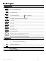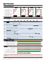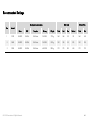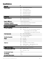
1
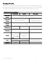
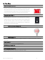
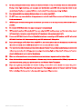
NAZA-M LITE User Manual V 2.00 2014.04.21 Revision For Firmware Version V1.00 & Assistant Software Version V1.00 Thank you for purchasing this DJI product. Please strictly follow these steps to mount and connect this system on your aircraft, as well as to install the Assistant Software on your computer. Please regularly check the NAZA-M LITE web page at our website www.dji.com for latest information. Product information, technical updates and manual corrections will be available on this web page. Due to unforeseen changes or product upgrades, the information contained in this manual is subject to change without notice. * This manual is only for basic assembly and configuration; you can obtain more details and advanced instructions when using the assistant software. To assure you have the latest information, please visit our website and download the latest manual and current software version. If you have any problem that you cannot solve during usage, please contact your authorized dealer. www.dji.com ©2014 DJI. All Rights Reserved. Warning & Disclaimer NAZA-M LITE is an excellent autopilot system offering tremendous flight features for low altitude multi-rotor working in restricted space compared to normal helicopter. It is not a toy when installed in multi-rotors of any size. Please respect the AMA’s National Model Aircraft Safety Code. Despite our efforts in making the controller to operate in the safest manner when the main power battery is connected, such as: disabling MC signal to ESCs when USB is connected; disabling throttle input and stick command when throttle stick is not at the lowest position, we strongly recommend customers to remove all propellers, use power supply from R/C system or flight pack battery, and keep children away during system calibration, firmware upgrade and parameter setup. DJI Innovations assumes no liability for damage(s) or injuries incurred directly or indirectly from the use of this product. Please strictly follow these steps to mount and connect NAZA-M LITE on your multi-rotor, as well as to install the assistant software on your computer. DJI and NAZA-M LITE is registered trademark of DJI Innovations. Names of product, brand, etc., appearing in this manual are trademarks or registered trademarks of their respective owner companies. This product and manual are copyrighted by DJI Innovations with all rights reserved. No part of this product or manual shall be reproduced in any form without the prior written consent or authorization of DJI Innovations. No patent liability is assumed with respect to the use of the product or information contained herein. ©2014 DJI. All Rights Reserved. 2 Product Profile NAZA-M LITE for multi-motors is an autopilot system designed for serious multi-rotor enthusiasts providing excellent self-leveling and altitude holding, which completely takes the stress out of flying RC multi-rotors for both professional and hobby applications. NAZA-M LITE can be installed in a variety of models from quad-rotor to hexa-rotor. No GPS Atti. Mode without GPS module NAZA-M LITE Control Modes GPS Atti. Mode Rudder Angular Atti. Mode Maximum rudder angular velocity is 200°/s Velocity Command Stick Multi attitude control; Stick center position for 0˚ Meaning attitude, its endpoint is 45˚. Command Altitude Lock Lock position if GPS signal is adequate. Only attitude stabilizing. ground. has been lost for 3s, system enters Atti. Mode automatically. Safety attitude angle limitation and vertical velocity locking. Maintain the altitude best above 1 meter from When GPS signal GPS Lost Max-angular velocity is 150°/s. No YES Linearity Stick Released Manual Mode stabilizing without --- position lock. Enhanced Fail-Safe Auto Level Fail-Safe AP work Sports flying. ©2014 DJI. All Rights Reserved. NO Only performing attitude Attitude & speed mixture control ensures stability Applications NOT Recommend Depends on experience. --- 3 In The Box Main Controller (MC) ×1 The Main Controller (MC) is the brain of the system, it communicates with all ESCs and RC transmitter to carry out the autopilot functionality. It has a builtin Inertial Measurement Unit (IMU) consists of one 3-axis accelerometer, one 3-axis gyroscope and a barometer for sensing the attitude and altitude. Versatile Unit (VU) ×1 Specially designed for NAZA-M LITE. It solves the high power consumption problem of multi-rotor system, supply and monitor power for NAZA-M LITE and other electronic devices. It also has an LED to indicate different operating states of NAZA-M LITE and a USB interface for configuring the NAZA-M LITE unit and firmware upgrade. Optional GPS & Compass Module ×1 The GPS/Compass module is for sensing the position and direction. Optional GPS Bracket ×1 Because the GPS & Compass are sensitive to magnetic interference, you should use this bracket to mount the GPS module. USB Cable ×1 This cable is used to configure MC and upgrade firmware. 3-PIN Servo Cable ×8 Cables used to connect the MC and the receiver. 3M Gummed Paper ×4 Used for fixing NAZA-M LITE components on multi-rotor’s frame. ©2014 DJI. All Rights Reserved. 4 Contents WARNING & DISCLAIMER ...........................................................................................................................2 PRODUCT PROFILE .....................................................................................................................................3 IN THE BOX..................................................................................................................................................4 CONTENTS ..................................................................................................................................................5 MATTERS THAT NEED ATTENTION ............................................................................................................6 ASSEMBLY ...................................................................................................................................................8 ASSISTANT SOFTWARE...............................................................................................................................9 SOFTWARE AND DRIVER INSTALLATION ............................................................................................................... 9 GUI .................................................................................................................................................................. 11 FIRMWARE UPGRADE ........................................................................................................................................ 12 PRODUCT INFO ................................................................................................................................................. 12 CONFIGURATION ..................................................................................................................................... 13 BASIC ......................................................................................................................................................... 13 1 AIRCRAFT ....................................................................................................................................................... 13 2 MOUNTING .................................................................................................................................................... 14 3 RC ................................................................................................................................................................ 15 4 GAIN ............................................................................................................................................................. 18 ADVANCED................................................................................................................................................ 20 1 MOTOR .......................................................................................................................................................... 20 2 F/S ............................................................................................................................................................... 23 3 IOC .............................................................................................................................................................. 25 4 GIMBAL ......................................................................................................................................................... 30 5 VOLTAGE ...................................................................................................................................................... 32 FLIGHT ....................................................................................................................................................... 35 DIGITAL COMPASS CALIBRATION ...................................................................................................................... 35 FLY TEST........................................................................................................................................................... 37 FLY WITH GPS .................................................................................................................................................. 39 APPENDIX .................................................................................................................................................. 40 FIX THE TBE (TOILET BOWL EFFECT) PROBLEM ................................................................................................ 40 IMU CALIBRATION ............................................................................................................................................ 41 PORT DESCRIPTION .......................................................................................................................................... 42 LIGHT DESCRIPTION.......................................................................................................................................... 43 RECOMMENDED SETTINGS ................................................................................................................................ 44 SPECIFICATIONS ............................................................................................................................................... 45 ©2014 DJI. All Rights Reserved. 5 Matters That Need Attention For safety reasons, please pay serious attention to all following items: 1. For big aircraft that is larger than 650 or with heavy load, WKM is recommended. 2. When aircraft is set-up with all of the equipment that you are going to use, please ensure the aircraft center of gravity is on the center Line of the frame, this is for aircraft with its load is in the vertical direction of frames center. 3. When MC mounted, try your best to mount the MC at the center of the frame, and do not mount the MC upside-down. Make sure MC is parallel to the aircraft horizon, so as to prevent the aircraft from drifting in horizontal direction. 4. Make sure the MC ESC ports is pointing to the aircraft nose direction, otherwise serious damage will occur to your aircraft. 5. Disconnect ESCs and battery or remove all propellers during firmware upgrade, configuration and system setup! 6. You have to reboot MC and redo the TX calibration after you change anything on the RC system. 7. In the TX Calibration of assistant software: 8. Throttle: Slide left is craft down, slide right is craft up; Rudder: Slide left is nose left, slide right is nose right; Elevator: Slide left is craft back, slide right is craft front; Aileron: Slide left is craft left, slide right is craft right. When powering up the Craft, Make sure you turn on the Transmitter switch first, then Plug in the FC Battery power on multi-rotor before takeoff! After your Flying Session and you want to power down, make sure you Remove Power to the multi-rotor first, and then switch off the transmitter! 9. Whether you are using gimbal control in assistant software or not, there is always power output from F1 and F2 ports. Do not connect these ports to any ESCs which are wired with propellers and motors. 10. Do NOT set the failed-safe position of throttle under 10% of endpoint. 11. Throttle stick position should always be higher than 10% from cut-throttle during the flight! 12. The NAZA-M LITE-M has Low voltage protections! If you are seeing a Red Flashing light, you should land your multi-rotor ASAP to prevent your multi-rotor from crashing or other harmful consequences! 13. when using the (Immediately mode) to stop the motors, this is in any control mode, once the motors start and throttle stick is over 10%, When the throttle stick lowered below 10% the motors will stop immediately .But if you push the throttle stick over 10% within 5 seconds after motors stop, the Motors will re-start; Combination Stick Command (CSC) is not needed. If you don’t push throttle stick after motors start in three seconds, motors will stop automatically. ©2014 DJI. All Rights Reserved. 6 14. By using Intelligent mode to stop motors, the motors will start or stop immediately when you execute CSC. During normal flight conditions, you only have pull throttle stick under 10% will not stop the motors in any control mode. You have to execute CSC to re-start motors if the motors stop during the flight. 15. Red light quick blinking indicates battery voltage is low, please land ASAP. 16. Do NOT move any command sticks during system start and self-check! Please contact us if the last four green blinks are abnormal. 17. GPS/Compass is sensitive to magnetic interference; you should be as far away from any electronic devices as possible. 18. Do not fly in GPS Mode when the signal is not good (red light blinks)! 19. GPS module is optional (Nonstandard). If you are using the GPS module, please read the Instructions about GPS matching in indicators; users without the GPS module can skip contents about GPS. 20. If users set GPS Atti. Mode in Control Mode Switch without connecting to GPS module, the M.C. will switch GPS Atti. Mode into Atti. Mode automatically, and LED indicator will Blink yellow. 21. If you are working in the Fail-Safe Mode, with GPS on, the aircraft motors will auto Automatticly shut off when the craft has landed; without GPS the aircraft will not auto shut off when landed. 22. The receiver should be installed under the bottom board of center frame, and the head of antenna is downward without any obstacles, this will help prevent any signal loss during flight and the aircraft will be out of control, since the Radio signal may be lost by the obstacle. 23. Make sure all connections are correct and attachment contacts are in good condition before flight. 24. Keep wireless video transmission equipment a distance away from the main controller (>25cm), to prevent the main controller from getting any interference from the Wireless Video Transmitter. 25. If you use a gimbal, please make sure that the working current of the servos should not exceed the power supply capacity of the VU; otherwise, it may cause the VU safeguard and lead to the main controller reboot. Refer to the Specification section in the Appendix to get more VU parameters. ©2014 DJI. All Rights Reserved. 7 Assembly VU R/C System · These are example connections. Please setup Aileron, Elevator, Throttle, Rudder channels on your TX first, and choose o n e 2 positions switch/channel ( 3 positions switch with GPS) as control mode switch, then connect your receiver to the right ports on MC. · · · To Battery · · 2/3-position switch channel R/C Receiver (JR) RUDD ELEV AILE THRO · · 1 2 3 4 R/C Receiver (Futaba / Hitec) 接电调 ESC M1-6 2/3-position switch channel Do not mount it on any other electronic devices. Make sure You can see the LED light during the flight. If use with DJI multi-rotor, you can solder the VU power cable to power pads on frame bottom board. Please refer to DJI multi-rotor manual for details. If use with 3 rd part multi-rotor, you can make a connecter by yourself to connect VU, ESCs and battery. Sufficient air flow over the VU is highly recommended. ESCs, Motors Motors and ESCs in DJI multi-rotor kit are recommended. Please make sure you are using the ESCs and motors recommended by the manufacturer of your multi rotor first. NAZA-M LITE output is 400Hz refresh frequency. Connect all ESCs to MC by the motor numbering method introduced in Multi-Rotors Supported of Appendix. If you use 3rd party ESCs, please make sure the ESCs travel midpoint is at 1520us. DO NOT use 700us travel midpoint ESC, as it may lead aircraft to fly away or cause injury and damage. After connect ESCs to motors, calibrate all your ESCs one by one through the receiver directly before connect them to your MC, Make sure program all of them into Governor off, Break off and Normal Start up to get best experience. 接云台 Futaba S-Bus S-Bus F2 Roll Aircraft Nose Pitch F1 GPS/COMPASS · · Optional · · · ©2014 DJI. All Rights Reserved. GPS/Compass is sensitive to magnetic interference, should be far away from any electronic devices. You should use epoxy resin AB glue to assemble the GPS bracket first as the figure showed in previous page. Mount the bracket on the center plate of craft first, then fix the GPS on the plate of the bracket (by 3M glue provided). The GPS is sensitive to vibration interference, so position the bracket at least 10 cm from any rotor. The DJI logo marked on the GPS should face the sky, with the orientation arrow pointing directly forward. The GPS/Compass is packaged with a special indication line for mounting for the first time. If you are uncertain whether materials near the GPS/Compass module are magnetic or not, you can use a compass or magnet to check it. If you use your own mounting rod, make sure it is NOT magnetic! Important: the continuous output of the V U is 3A@5V, and the maximum instant current is 7.5A. If the V U cannot afford the working current for you r servos, please use an independent power supply; otherwise, it may cause the V U safeguard and lead to the main controller reboot. MC · Please use 3M gummed paper provided To mount MC, and mount MC parallel to the aircraft horizon. · The output ports of MC (the right side in figure) should point to the front of multi-rotor. You’d better put MC at the gravity center of multi-rotor. Please make sure all ports are accessible when installing the MC so as to facilitate wiring and software configuration. · In three-pin ports, pins near the nicks are signal pins. · After choosing a location to mount the MC, it is recommended that you DO NOT mount the MC until all wirings and software configurations are completed. 8 Assistant Software Software and Driver Installation Installing and running on Windows 1. Please download the driver and the Assistant installation software in EXE format from www.dji.com. 2. Switch on the transmitter and then power on your autopilot system. 3. Connect your autopilot system and PC via a Micro-USB cable. 4. Open the driver installation software and follow the instructions to complete installation. 5. Run the Assistant installation software and follow the instructions to complete installation. The installer in EXE format only supports Win XP, Win7, Win8 (32 or 64 bit). Installing and running on Mac OS X 1. Download the Assistant installer in DMG format from the download page of NAZA-M LITE on the DJI website. 2. Run the installation software and follow the prompts to finish installation. 3. When launching for the first time if use Launchpad to run the NAZA-M LITE Assistant Software, Launchpad won’t allow access because the software has not been reviewed by Mac App Store. 4. Locate the NAZA-M LITE icon in the Finder and open the file by Control or right clicking the icon and selecting “Open” from the menu. 5. After the first successful launch, double-clicking the NAZA-M LITE icon in the Finder or using Launchpad will open the application. ©2013 DJI Innovations. All Rights Reserved. 9 Installer in DMG format supports only Mac OS X 10.6 or above. The NAZA-M LITE Assistant on Mac OS X and Windows are exactly the same. The Assistant Software pages appear in other places of this manual are screenshots of the Windows version for example. ©2014 DJI. All Rights Reserved. 10 GUI View 1 Basic Settings: Aircraft, RC, Mounting, Gain and Channel Monitor. Advanced Settings: Motor, F/S, IOC, Gimbal and Voltage. 2 Basic: Set the Aircraft, RC, Mounting, Gain and Channel Monitor. 3 Advanced: Set the Motor, F/S, IOC, Gimbal and Voltage. 4 Tools: IMU calibration. 5 Upgrade: Upgrade your modules firmware. 6 Info: Check the user information. 7 English: Select the language. Notices: Please power the MC first, then connect your MC to a internet enabled computer by the USB cable before you open the assistant software. You have to register at the first time you use the assistant software. It will auto detect the software version you have when you open the assistant software and prompt you to Check for Updates if your version is not the latest one. Do not disconnect MC and PC when you are using the assistant software.. ©2014 DJI. All Rights Reserved. 11 Firmware Upgrade Please follow Word for Word in the procedure for firmware upgrade; otherwise the autopilot might not work properly. For SAFETY REASONS, DO NOT use power battery during firmware upgrade. 1. Make sure your computer is connected to the Internet before you connect the USB cable to the MC. 2. Please close all the other applications during the firmware upgrade, including anti-virus software and firewall. 3. Make sure the power supply is securely connected. DO NOT un-plug the power supply until firmware upgrade has finished. 4. Connect MC to PC with micro-USB cable, DO NOT break connection until firmware upgrade is finished. 5. Run Software and wait for connection. 6. Select Upgrade page. 7. Server will check your current firmware version, and get the latest firmware prepared for the unit. 8. If there is a firmware version more up-to-date than your current version, you will be able to click the Upgrade button. 9. Wait until Assistant software reads finished. 10. Click OK and cycle the power of the unit after at least 5 seconds. Your unit is up-to-date now. Notices: After firmware upgrade, please re-configure the MC by Using the Assistant software. If the network or server is busy, please try again later with above procedures. If firmware upgrade failed, MC will enter waiting for firmware upgrade status automatically, please try again following the above procedures. Product Info You can check the Assistant Software version via Info. S/N is a 32 digits authorization code for unit function activations. We had already filled in the authorization code for your unit after manufacture. In the Future you might be asked to fill in the new S/N in the future if you brought new function upgrades. Fill-in the S/N and then click Write button. If you filled in an invalid S/N over 30 times, your MC will be locked and you have to contact our customer support. ©2014 DJI. All Rights Reserved. 12 Configuration Basic 1 Aircraft In the diagrams of each Mixer Type, the marks M1~M6 correspond to the output ports (M1~M6) on the Main Controller (MC). The direction of the arrow indicates the rotation direction of the motor. Make sure the rotation direction of each motor is the same as the diagram shows. If not, swap over any of two wire connections of the incorrect motor to change its rotation direction. Make sure the type of propeller matches the rotation direction of the motor. Blue propeller is at Top; Red propeller is at Bottom. ©2014 DJI. All Rights Reserved. 13 2 Mounting Install all payloads that will be used during the flight, including batteries, camera mount and camera. Balance the multirotor as you would normally, with the center of gravity (C.G.) directly on the center plate. Fill in the distance between body center of GPS and the C.G. of multi-rotor in X, Y & Z axles as showed in the figure. Make sure the MC ESC ports is pointing to the aircraft nose direction, otherwise serious damage will occur to your aircraft. When MC mounted, try your best to mount the MC at the center of the frame, and do not mount the MC upsidedown. Make sure MC is parallel to the aircraft horizon. Notices: 1 Users with GPS module please mount GPS location. 2 Please follow the requirements to mount your NAZA-M LITE MC, so as to prevent the aircraft from abnormal, such as drifting in horizontal direction, or even rollover. 3 You must re-configure if the ALL-UP-WEIGHT had been changed on your multi-rotor, 4 If GPS mounting locations are not accurate enough or the signs are wrong, error on X, Y,Z axles will leads the oscillation of your multi-rotor. 5 Make sure to follow the diagram in our assistant software: red is positive, green is negative; unit of measure is CM, NOT INCH. ©2014 DJI. All Rights Reserved. 14 3 RC STEP1: Receive Type Choose the type of receiver connection that you have installed. Connect your receiver to the main controller in accordance with the connection diagram. STEP2: Command Sticks Calibration Slides Moving Definition: T : If you pull the throttle stick to low position, the Slide will move to the left and the craft is down, Moving the Throttle stick up the slide will move to the right is craft will lift off the ground; R : If you move the rudder stick to the Left the Slide will move to the left, this is nose left, When you move the rudder to the Right the slide move to the right, this is nose right; E : If you move the Elevator stick down the Slide will move to the left and the craft will move back, Moving ©2014 DJI. All Rights Reserved. 15 the Elevator Stick up the Slide will move to the right and the craft will move Foward (away from you); A : If you move the Aileron stick to the left the Slide will move left and the craft will move to the left, when you move the Aileron stick to the Right the slide will move to the right and the craft will move to the right. 1. Set endpoints of all channels to default values (100%) and set all trims and sub-trims of sticks to 0 on your transmitter first. Keep all curves’ settings as default since the end-point of transmitter sticks will be recorded here. 2. Click the START button, and move all of the sticks throughout their complete range several times. 3. After you do this, click the FINISH button when you have finished the above procedures. 4. If the slides are moving opposite from your stick movements direction, click the reverse button REV/NORM beside. Notices: 1. All slides should become when all the sticks are in the middle positions. If slides cannot go back to center points (become ), just click FINISH, then slides will be at center automatically. If still not, please reboot MC, and do not apply TX command during the reboot. 2. CSC may not start motors If trims and sub-trims of sticks are not 0! STEP3: Sticks Monitor This step is optional. If it is necessary for you, please setup the channel on your R/C TX correctly, and then you can monitor the X1 and X2 Channels on this page. Tips: X1 Channel is for remote gain tuning or gimbal pitch control. X2 Channel is for remote gain tuning or Intelligent Orientation Control (IOC), or as S-Bus input. Receive Type Receive Type STEP4: Control Mode Switch Whether you are using a 2 or 3 position switch on your transmitter will determine which you will use as the control mode switch, Plug in the right channel of receiver (Gear, Aux 1 or aux 2) to the U port of MC. At each switch position, use the end-point for fine tuning on your transmitter, Move the Switch to the corresponding Mode as indicated by the slider of channel U to GPS (GPS Atti Mode), A (Atti. Mode), M (Manual Mode) to turn the corresponding area blue respectively as showed in the figure. ©2014 DJI. All Rights Reserved. 16 Tips: To move the slider is to adjust channel-selected end-points. For 3-position switch, you should assign: Position-1 to Manual Mode; 3 Position Switch 1 2 3 Tx 2 Position Switch Position-2 to Atti. Mode; Position-3 to GPS Atti. Mode; or reverse 1 2 Tx the assignment for Position-1 and Position-3. For 2-positions switch, you can assign any two of these three control modes as you like. If your transmitter supports Fail-Safe, follow the Fail-Safe setting procedure of your R/C TX. Then move the slider to the range which makes Fail-Safe Mode turn blue, set Fail-Safe output of receiver to input port-U. If you switch off your transmitter now, the U channel slide should move to Fail-Safe and turn the corresponding area to blue. Otherwise please reset the fail-safe. MC has built-in auto level Fail-Safe function. That means when the communication between MC and transmitter is disconnected, the outputs of all command sticks from MC will go to center point. If your transmitter has only 4 channels, then MC will work in Atti. Mode by default without the Fail-Safe function. Tips: Please refer to your RC manual for the details of fail-safe setup. With GPS, it is Enhanced Fail-Safe; without GPS, it is Auto Level Fail-Safe, and the aircraft will land. Notices: 1. Do NOT set the fail-safe position of throttle under 10% of endpoint. 2. MC will not execute the Fail-Safe protection if you don’t set it properly. You can verify the Fail-Safe settings by shutting down your transmitter, and then you can use the following method to check whether MC is already in Fail-Safe mode. 3. Check status bar at the bottom side of the software interface. If the Fail-Safe has been correctly set-up the Control mode will change to Fail-Safe. 4. Check the LED indicator. Read the appendix in this manual for details. LED will give fast yellow blinking if in fail-safe mode. 5. If your transmitter does not support Fail-Safe, the Fail-Safe function will not work when the communication between MC and transmitter is disconnected. 6. Do not use 4-channel Futaba transmitter with S-Bus receiver, otherwise MC will work in Fail-Safe mode. 7. If users set GPS Atti. Mode in Control Mode Switch without connecting to GPS module, the M.C. will switch GPS Atti. Mode into Atti. Mode automatically, and LED indicator will Blink yellow, that is if the 3poisition switch is the same as 2-position switch. 8. Once the MC goes into the Fail-Safe Mode, and you are using the GPS, the aircraft will auto Stop the Motors when landed; without GPS the aircraft the motors will not auto Stop when landed. ©2014 DJI. All Rights Reserved. 17 4 Gain Usually, the default parameters are ready to go. However, different multi-rotors have different gains because of different Motor KV ratings, ESC and propeller sizes. If the gain is set too high, you will find the multi-rotor will be oscillating in the corresponding direction (About 5~10Hz). If the Gain is too low, the multi-rotor will likely to be hard to control. So you can still setup the basic Gain of Pitch, Roll, Yaw and Vertical manually according to your multi-rotor to have a wonderful flying experience. We suggest you to change 10% to 15% of the parameter at a time. For the gains of the Pitch and Roll, if you release the Pitch or Roll stick after giving a command, the multi-rotor should go back to a hovering state. If the reaction of multi-rotor in this procedure is too soft (large delay), please increase the basic gain slowly (10%-15% each time) after you release the stick until vibration begins. Then decrease the gain a little until vibration just disappears. Now the gain is perfect, but the reaction of the attitude change is slow. Follow the Procedure at the end of this section to tune the attitude gains. The way of tuning the Yaw gain is the same as the way of adjusting the Tail Gyro. If you want fast stick reaction speed, increase the gain, otherwise decrease the gain. However, the spin of multi-rotor is produced by the counter torque force, and the magnitude of which is limited. Therefore, large gain will not produce tail vibration like helicopter, but severe reaction at the start or stop of motors, which will affect the stabilization of the other directions. ©2014 DJI. All Rights Reserved. 18 You will use two methods to judge if the Vertical gain is good enough: 1) The multi-rotor can lock the altitude when the throttle stick is at center position; 2) The change of altitude is small during the flight along a route. You can increase the gain slowly (10% each time) until the vibration emerges along the vertical direction or the reaction of throttle stick is too sensitive, then decrease 20% of the gain. Now it is a suitable Vertical gain. Attitude gains determine the reaction speed of attitude from command stick, the Larger the value the quicker the reaction. Increase it for sharper and quicker leveling action after command stick released. Unstable shaking flying and the control feeling will be stiffness and rigid if the value is too high; and sluggish leveling action and slow braking if too small. Notices: You must upgrade firmware first, then click Default button in first setup parameter. The vertical gain will NOT affect the manual mode. The final flight performance is decided by the autopilot parameters and all parts of multi-rotor (includes mechanical structure, motors, ESCs, propellers and battery). If these parts are not compatible, you cannot get good flight performance by adjusting the autopilot parameters. Therefore, if you have high requirement to flight performance, you’d better get a multi-rotor with good integration test. Tips: If you are new to multi-rotor flying, you can tune the basic parameters first as following: 1 Increase the basic parameters 10% at a time so as to make your multi-rotor hover or light oscillate after small angular command input. 2 Decrease the basic parameters until your multi-rotor can just hover, then decrease 10% more. Here you can make use of remote gain-tuning channels to tune the gains during the flight: 1 Followed the instructions in Assembly R/C System section to connect and setup correctly; 2 Choose the X1 or X2 channel in Remote Adjust for the gain you want to tune. One channel to one gain. 3 The range of remote tuning is from half the current value to twice the current value. Usually the Pitch, Roll, Attitude Pitch and Attitude Roll Gains of hexa-rotor are high then quad-rotor. ©2014 DJI. All Rights Reserved. 19 Advanced 1 Motor STEP1:Motor Idle Speed Motor Idle Speed is the lowest speed after motors start. Setting the Motor Idle Speed will affect the motors lowest speed after the motors start. There are five levels from LOW speed to HIGH speed, and the default is RECOMMEND. You can click and drag cursor LOW to the corresponding level, to change Motor Idle Speed. RECOMMEND The lower motor idle speed HIGH The higher motor idle speed Setting the Motor Idle Speed as LOW, the motor idle speed will be at its lowest point. Setting the Motor Idle Speed as HIGH, the motors idle speed will be at its highest. RECOMMEND is the advised level. You can reset the Motor Idle Speed according to your personal preference. ©2014 DJI. All Rights Reserved. 20 Notices: For users whose aircraft takes off at lowest throttles position, please set the idle speed at a low level. For common users, please set Motor Idle Speed to RECOMMEND or above, since setting idle speed too low may affect motor(s) spool up. Tips: The output pulse width for every grade of Motor Idle Speed is as followed LOW output pulse width 1144 us RECOMMEND 1160 us 1176 us HIGH 1192 us 1208 us There is relationship between the output pulse width and the max/min pulse width when TX End Point is 100%. output pulse width=(max pulse-min pulse) x proportion + min pulse You can get the proportional values by computing according to the above formula for a special TX. Use Futaba TX for example. Notice that Futaba TX End Point is 100%. LOW proportion value 3% RECOMMEND 5 7% HIGH 9% 11% STEP2:Cut Off Type Please read the introductions of start and stop motor in this step first, and then choose a cut off type. 1 Start Motor: Pushing throttle stick before takeoff will not start the motors. You have to execute any one of following four Combination Stick Commands (CSC) to start the motors: 2 Stop Motor: We provide two options to stop motors: Immediately and Intelligent. Immediately Mode: If you select this mode, in any control mode, once motors start and throttle stick is over 10%, motors will not stop immediately only when throttle stick is back under 10% the motors will stop. In this case, if you push the throttle stick over 10% within 5 seconds after motors stop, motors will re-start, CSC is not needed. If you don’t push throttle stick after motors start in three seconds, motors will stop automatically. Intelligent Mode: By using this mode, different control mode has different way of stopping motors. In Manual Mode, only executing CSC can stop motors. In Atti Mode or GPS Atti. Mode, any one of following four cases will stop motors: a) You don’t push throttle stick after motors start within three seconds; b) Executing CSC; c) Throttle stick under 10%, and after landing for more than 3 seconds. ©2014 DJI. All Rights Reserved. 21 d) If the angle of multi-rotor is over 70°, and throttle stick under 10%. Tips (Intelligent Mode): You have to execute CSC in order to re-start the motors. By pushing the throttle stick only will not restart the motors. In Atti. / GPS Atti. Mode, it has landing judgment, which will stop motors. Start motors in Atti. / GPS Atti. Mode, you have to execute CSC and then push throttle stick over 10% within 3 seconds, otherwise motors will stop after 3 seconds. During normal flight, only pulling the throttle stick under 10% will not stop motors in any control mode. For safety reasons, when the slope angle of multi-rotor is over 70° during the flight in Atti. / GPS Atti. Mode (may be caused by collision, motor and ESC error or propeller broken down), and throttle stick is under 10%, motors will stop automatically. You can stop motors by executing CSC in any control mode. Notices: Any of these two cut off types will only work properly if TX calibration is correct done. The motors will start or stop immediately when you execute CSC when TX commands are valid under any of the control modes. It has nothing to do with current throttle stick position. Please DO NOT execute the CSC during flight unless safety is at stake. If you choose the Immediately mode, you should not pull throttle stick under 10% during flight, because that will stop the motors. If you do it accidentally, you should push the throttle stick over 10% within 5 seconds to re-start the motors. If you choose the Intelligent mode, and the throttle stick is under 10%, this will trigger the landing Procedure, in any control mode. In this judgment, pitch, roll and yaw controls are denied except the throttle, but multi-rotor will still auto level. In any control mode, DO NOT pull throttle stick under 10% during normal flight without any reason. In failed-safe, CSC is denied by MC, motors will hold their state. ©2014 DJI. All Rights Reserved. 22 2 F/S Enhanced Fail-safe method will be triggered when MC loses the control signal, no matter what mode you fly. This could be one of the following situations: 1) Signal lost between transmitter and receiver, e.g. multi-rotor is out of the communication range, or transmitter is down, and so on. 2) One or more connections of A, E, T, R, U channels between MC and receiver loses. If this happens before takeoff, motors will not work if you push the throttle stick; if this happens during the flight, LED yellow light will flash to warn in addition to the failed-safe method. Choose one method for your failed-safe function: Landing or Go Home and Landing. Landing: the aircraft will land after 6s hovering. Go Home and Landing: Before takeoff, current position of multi-rotor will be saved as home point by MC automatically when you push the throttle stick first time after 6 or more GPS satellites are found ( blinks once or no blinking) for 8 seconds. Notices: When switch to Manual Mode or Atti. Mode, MC will disengage enhanced failed-safe mode, you can re-gain control of multi-rotor. ©2014 DJI. All Rights Reserved. 23 Tips: The following schematic shown is introduction for Go-Home and Landing. Home Location If GPS satellite found >= 6 , at the first you pull the throttle stick, then record Home Location Ground Multi rotor 1 Stay hover Signal lost Tx Tx 2 3 Current location higher than 20m Ready to Go-Home Go back first 20m Signal lost > 3s Tx 4 ©2014 DJI. All Rights Reserved. Hover 15s , Then land. Current location lower than 20m Tx Tx 5 6 24 3 IOC Forward Direction: Multi-rotor will fly along this direction when you push the elevator stick. Usually, the forward direction of a flying multi-rotor is the same as the nose direction. By using Intelligent Orientation Control (IOC), wherever the nose points, the forward direction has nothing to do with nose direction: In course lock flying, the forward direction is the same as a recorded nose direction. See the following figures (Mode 2): Usually In course lock In home lock flying, the forward direction is the same as the direction from home point to multi-rotor. See the following figures (Mode 2): ©2014 DJI. All Rights Reserved. 25 Usually In home lock Home point Home point Before using this function, you have to choose a 2 or 3 positions switch on your transmitter as IOC switch. Then connect a wire to the correct channel of receiver to the X2 port of MC. At each switch position, use end-point fine tuning on your transmitter, move the slider of channel X2 to Home Lock, Course Lock, OFF to turn the corresponding area blue respectively. Tips: 3 Position Switch For 3-position switch: 1 2 3 Tx Position-1 is OFF; Position-2 is Course Lock; Position-3 is Home Lock. For 2-position switch: Position -1 is OFF; Position-2 is Course Lock. Or Position -1 is OFF; Position-2 is Home Lock. If you use S-Bus/PPM receiver, the default channel connection is shown in TX Monitor – Receiver Type section. Then you only need to assign a 2 or 3-position switch of your transmitter to the 6th channel. Notices: Do NOT set a 2-position switch as: Position-1 is Course Lock; Position-2 is Home Lock. Course Lock Usage: During the same flight: STEP1: Record STEP2: Open STEP3: Close Nose direction; Forward direction STEP4: Re-open STEP1:Record forward direction: There are two ways: Manually; Automatically: a) Automatically: MC will record the current nose direction as forward direction at 30th second after you power on the multi-rotor. And LED will blink b) quickly if recording is successful. Manually: You can slide X2 channel switch between OFF and Course Lock position quickly 3 to 5 times to record current nose direction as new forward direction at any time after you power on multi-rotor 30 seconds. And LED will blink ©2014 DJI. All Rights Reserved. quickly if recording is successful. 26 STEP2: Open course lock: After record the forward direction successfully, if MC is in Atti. or GPS Atti. Mode, then you can slide X2 channel switch to Course Lock position to fly in course lock. Now wherever the nose points, the real flight forward direction is the same as the recorded forward direction, and LED will blink STEP3: slowly to indicate the IOC mode. Close course lock: There are two ways: a) Slide X2 channel switch to OFF position to quit course lock; (Recommended way!) b) Slide U channel switch to Manual Mode position, or close transmitter. STEP4: Re-open course lock: If you want to re-open course lock after you quit this function, you should first slide X2 channel switch to OFF position, and slide U channel switch to Atti. or GPS Atti. mode position, then slide X2 channel switch to Course Lock position to re-open course lock. Home Lock Usage: During the same flight: STEP1: Record STEP2: Open Nose direction; Forward direction; STEP3: Close Home point; STEP4: Re-open Over 10m distance STEP1:Record home point: The home point mentioned here is the same home point of enhanced Fail-Safe. There are two ways to record them: Manually and Automatically: a) Automatically: Before takeoff, the current position of the multi-rotor will be saved as home point by MC automatically when you push the throttle stick for the first time after 6 or more GPS satellites have been found ( b) blinks once or no blinking) for 8 seconds. Manually: When 6 or more GPS satellites are found ( blinks once or no blinking), you can toggle the X2 channel switch between (to a 3-position switch) Course Lock and Home Lock or (to a 2position switch) OFF and Home Lock position quickly 3 to 5 times to record the current position of the multi-rotor as the new home point. And LED will blink STEP2: quickly if recording is successful. Open home lock: flip the X2 channel switch to the Home Lock position to fly in home lock when all the following requirements are met: a) Home point is recorded successfully; b) 6 or more GPS satellites are found; c) In GPS Atti. Mode; d) Multi-rotor is further than 10m away from the home point. ©2014 DJI. All Rights Reserved. 27 Now wherever the nose is pointing, the real flight forward direction is the same as the direction from the home point to the multi-rotor, and LED will blink between yellow and green slowly to indicate the IOC mode of MC. STEP3: Close home lock: There are three ways: a) Flip the X2 channel switch to the OFF position to quit home lock; (Recommended way!) b) Flip the U channel switch to Manual Mode position, or turn off the transmitter. c) The MC will be in course lock by the current forward direction automatically when multi-rotor flies back into 10m range around home point, or MC is in Atti. Mode. STEP4: Re-open home lock: If you want to turn on home lock after you quit this function, you should first flip the X2 channel switch to the OFF position. When all 4 requirements in the 3rd step are met, flip the X2 channel switch to the Home Lock position to turn on home lock. Tips: 1 LED will blink between and slowly to indicate the IOC mode only when MC is really to fly in course lock or home lock modes. 2 We suggest that you should know clearly that, by which lock method you are going to fly, and the locked forward direction or home point, before you switch on IOC mode during the flight. 3 There is only one home point recorded at any time. This point is the same one used by Go-Home and Landing in the fail-safe mode. 4 When flying by home lock, if GPS signal becomes weak, MC will be in course lock in the current forward direction automatically. 5 You’d better stand near the home point to use home lick. 6 You’d better use 3-position switch for X2 channel, and you’d better use X2 channel switch to activate and deactivate the IOC during the flight. Notices: 1 Before you do the home lock flight, you have to fly the multi-rotor out of the 10m range around the home point; you have to flip the X2 channel switch to Home Lock position to fly in home lock when all the requirements are met. If you have already toggled the X2 channel switch to Home Lock position when the multi-rotor is still in 10m range around home point, and this is the first time you are going to fly in home lock during the current flight, then if all the requirements are met, MC will change into home lock automatically when multi-rotor flies out the 10m range around home point. 2 When multi-rotor is flying by home lock, far away from you and the home point, please do not toggle the X2 channel switch many times quickly so as to avoid the change of home point without you knowing it. 3 By using a 3-position switch, if you want to record the forward direction or home point manually, do not toggle the X2 channel switch between OFF and Home Lock position, but only between OFF and Course ©2014 DJI. All Rights Reserved. 28 Lock, or Course Lock and Home Lock position. And please record the forward direction and home point separately so as to make sure the recording is successful. 4 We suggest you to use Home Lock in a limited area which is 10m away from the home point. 5 Continuously spinning will cause a yaw error. In this case, you can stop or slow down the spinning, so as to have better flight performance. 6 When flying in Home Lock mode, if any of the following situations happen, then the system will quit Home Lock flying and automatically enter Course Lock flying. The aircraft will fly in Course Lock using the earlier forward direction The aircraft fly’s within 10m range of the home point. You toggle the control mode switch to the ATTI. Mode. The GPS signal becomes bad (The GPS signal LED is blinking Red twice or three times). ©2014 DJI. All Rights Reserved. 29 4 Gimbal STEP1: Gimbal Switch If you use gimbal, please choose On here, and select an Output Frequency (50Hz/100Hz/200Hz/400Hz). The chosen output frequency is recommended no more than the maximum servo supported frequency. Notices: If you open the gimbal control in assistant software during the configuration, please note that there are outputs from F1 and F2 ports. You should never connect these ports to ESCs which are wired with propellers and motors. Tips: NAZA-M LITE supports servo center 1520us. STEP2: Servo Travel Limit Range: -1000 to+1000 MAX/MIN are servo travel limits; adjust them to avoid mechanical binding; Place your multi-rotor on level ground, adjust Center value of Pitch and Roll direction to make the camera mounting frame to your desired angle-to-ground. ©2014 DJI. All Rights Reserved. 30 STEP3: Automatic Control Gain Range: 0 to 100 Adjust the reaction angle of the automatic control. The initial value of 100 is the maximum angle. The larger the gain, the bigger the reaction angle. Click REV/NORM, and then you can reverse the feedback control directions. STEP4: Manual Control Speed Range: 0 to 100 You should assign one of the knobs on your transmitter to the X1 channel for controlling the Pitch direction (angle) of camera gimbal during flight first. Then adjust the reaction speed of pitch direction manual control; the initial value 100 is the maximum speed. Notices: If parameter adjustment was enabled on channel X1, the gimbal manual control via channel X1 will still be on as well. Do not use X1 to control gimbal pitch and remote adjust parameters at the same time. Please reset the Basic Parameters in Autopilot section if there is flight jitter after gimbal is mounted. ©2014 DJI. All Rights Reserved. 31 5 Voltage STEP1: Protection Switch In order to prevent your multi-rotor from a crash or other harmful consequences caused by low battery voltage, there are two levels of low voltage protection available to use. You can choose to use or not to use them, however we strongly recommend using the protections available! Notices: Make sure the connection between VU and MC (V-SEN to X3) is correct; otherwise the low voltage protection will not work properly. Both levels of protection have LED warning as default. Both levels of protection will blink red continuously. Both level protections will only have the LED warning under Manual Mode, none in the automatic actions. Low voltage protections are NOT fun! You should land your multi-rotor ASAP in any level of protection to prevent your multi-rotor from crash or other harmful consequences! STEP2: Battery Apply battery power the MC and connect the MC with the PC, current battery voltage will be displayed in this column. ©2014 DJI. All Rights Reserved. 32 If the battery voltage displayed here is different from the voltage you measure from a voltmeter, you have to calibrate it. Click the Calibration box, enter that voltage in the Calibration column of the dialogue box, and then click Confirm. Meanwhile you need you to choose the battery type you are using, so that MC can provide the default warning voltages and ranges for you. STEP3: First Level Protection No Load (No Load Voltage): Self-defining warning voltage. Needs your input. Loss (Line Loss Voltage): The battery voltage drop during the flight. Needs your input. Loaded (Loaded Voltage): The real-time battery voltage during the flight. This is the actual warning voltage monitored by MC. Doesn’t need your input, calculated by No Load and Loss. Tips: Voltages Magnitude Relation: No Load: First level > Second level. Loss: First level = Second level. Loaded: Calculated, First level > Second level. Method of Acquiring Line Loss Voltage: 1 Make sure you can fly your multi-rotor normally with a fully charged battery. 2 Use a fully charged battery, switch on the low voltage protections in assistant software, and observe the current voltage. Fill a reasonable warning voltage in the No Load of first protection (We recommend to fill a voltage 1V lower than current voltage and higher than minimum battery voltage rating in). Fill 0V in Loss at the moment. 3 Fly the multi-rotor until the first level protection is triggered, and the red light is flashing. Now land your multi-rotor ASAP. 4 Connect the MC to PC, open the assistant and acquire new current voltage. The Loss (Line loss voltage) is the difference between the new current voltage and the first level No Load voltage you filled in. Notices: If the line loss voltage of a battery is over 0.3V per cell (e.g. 3S battery over 0.9V), it’s because the internal resistance of battery is high or the battery is too old, we suggest you to replace it! Generally the line loss voltages vary with different makes of batteries. For the consideration of safety, you’d better acquire all the line loss voltages of all your battery you are using, and fill the lowest one in the Loss box. When you change the payload or multi-rotor, you have to get new line loss voltages. The line loss voltage will be larger after many times of use, you should get new ones after 30 times of ©2014 DJI. All Rights Reserved. 33 charging. Make sure your ESCs protection voltage is lower than 3.1V (1S), otherwise low voltage protection will not work. Acquire the line loss voltage by the above method, and then fill it in Loss. Then fill a reasonable warning voltage in the No Load. Notices: When red LED starts to blink, you should land ASAP! STEP4: Second Level Protection 1 Fill the warning voltage and the line loss voltage in No Load and Loss by the method introduced in previous step. 2 When the second level protection is triggered, the LED warning will be on. Meanwhile the center point of throttle stick will move up slowly to 90% of endpoint, you should land ASAP to prevent your multi-rotor from crash or other harmful consequences! 3 When the center point is at 90% of endpoint, multi-rotor will still start to ascend slowly if you continue to pull the throttle stick back, and the control of Pitch, Roll and Yaw are the same as before. Please land ASAP to prevent your multi-rotor from crash or other harmful consequences! ©2014 DJI. All Rights Reserved. 34 Flight Digital Compass Calibration Without GPS, please skip this step Why calibrate the compass? Ferromagnetic substances placed on multi-rotor or around its working environment will affect the reading of earth magnetic field for the digital compass. It also reduces the accuracy of the multi-rotor control, or even reads an incorrect heading. Calibration will eliminate such influences, and ensure MC system performs well in a non-ideal magnetic environment. When to do it? The first time you install NAZA-M LITE on your multi-rotor. When the multi-rotor mechanical setup has changed: a) If the GPS/Compass module is re-positioned. b) If electronic devices are added/removed/ re-positioned (Main Controller, servos, batteries, etc). c) When the mechanical structure of the multi-rotor is changed. If the flight direction appears to be shifting (meaning the multi-rotor doesn’t “fly straight”). The LED blinking, often indicates abnormality blinking when the multi-rotor spins (It is normal for this to happen only occasionally) What not to do: Don’t calibrate your compass where there is strong magnetic interference, such as magnetite, car park, and steel reinforcement under the ground. DO NOT carry ferromagnetic materials with you during calibration, such as keys or cell phones. You don’t need to rotate your multi-rotor on a precise horizontal or vertical surface, but keep at least 45° difference between horizontal and vertical calibration. The GPS will not work in the polar circle. Calibration procedure STEP1: Quickly switch the control mode switch from Manual. Mode to GPS ATTI. Mode and back to Manual. Mode for 6 to 10 times, The LED indicator will turn to constantly yellow STEP2: Rotate your aircraft around the horizontal axis (about 360o) . until the LED changes to constant green , and then go to the next step. ©2014 DJI. All Rights Reserved. 35 Hold your aircraft vertically and rotate it (its nose is downward) around the vertical axis (about 360 o) STEP3: until the LED turns off, meaning the calibration is finished. STEP4: The LED indicator will show whether the calibration was successful or not. If the calibration was successful, calibration mode will exit automatically. If the LED keeps flashing quickly Red, the calibration has failed. Switch the control mode switch one time to cancel the calibration, and then re-start from step 1. Tips: If you keep having calibration failure, it might suggest that there is very strong magnetic interference around the GPS & Compass module, please avoid flying in this area. ©2014 DJI. All Rights Reserved. 36 Fly test Before First Flight Notices: Make sure you have assembled your multi-rotor correctly. Make sure you have done the configuration procedure correctly. Any of the following mistakes will leads to a dangerous accident, double check all these items: Rotation direction of motor is opposite Propeller installation mistake MC installation mistake Wrong connection between MC and ESC In Atti Mode, throttle stick center position is for 0m/s along the vertical direction. You must keep the throttle position higher than 10% from stopping the motors during the flight! Make sure you switch on the transmitter first, then power on multi-rotor! (Power off multi-rotor first, then switch off the transmitter after landing!) Please do the fly test and gain tuning with Atti. Mode in the open air without heavy winds! In Atti Mode, after power on and before motors start, if or LED double blinks without move any stick, this indicates that you have moved any sticks during system start up and check. You will have to reboot MC before you try to fly. Test Fly 1. Make sure your batteries are fully charged for your transmitter, MC and all the devices on your multirotor; 2. Check all connections and wirings, and make sure they are in good condition; 3. Switch on the transmitter first, then power on your multi-rotor! 4. Flip the control mode switch on your transmitter, and make sure it is working properly. Check it with LED indicator to specify the current working mode for MC. See Appendix for details about LED indicator; 5. Switch the system to Atti. Mode. Use any safe method to do the following test: Apply the throttle to 20% slowly and make sure all the motors are working properly, and then try to push your sticks lightly in Roll, Pitch and Yaw to feel if your multi-rotor moves to the corresponding direction. If not, go back to Configuration Procedure and correct your settings. 6. Push the throttle stick slowly within 3 seconds after executing CSC until all the rotors are working, and then take-off your multi-rotor gently Tips: ©2014 DJI. All Rights Reserved. 37 After a successful test fly, the preparation before taking off can be simplified: Put your multi-rotor on the level ground, turn on the transmitter first, then power on multi-rotor, then you can take off in Atti. Mode. If the aircraft drifts or spins in horizontal direction when hovering, please use IMU Calibration in TOOL of assistant software to observe sensor output. If there is bigger gyroscope bias, do gyroscope calibration according to the IMU Calibration in Appendix. ©2014 DJI. All Rights Reserved. 38 Fly with GPS Without GPS, please skip this step Before Fly with GPS Notices: When system is powered on, you must not move your multi-rotor or sticks on transmitter until the system initialization is finished (about 5 second). Make sure the GPS signal is good, without red LED blinking. Otherwise multi-rotor will drift without stick commands. Please avoid using MC system in the following areas, where will GPS signal is most likely blocked: Urban area with crowded buildings Tunnels Under bridges Tips: Should you find the multi-rotor does not track straight in forward flight, you might try re-mounting GPS in an offsetting angle as showed in right figure. Θ in the figure is the offsetting angle. Actual fli ion ght direct θ Objective flight direction GPS mounting direction 1 Without GPS offset angle With GPS offset angle 2 3 θ Actual flight direction Objective flight direction GPS mou nting dire ction ©2014 DJI. All Rights Reserved. 39 Appendix Fix the TBE (Toilet Bowl Effect) Problem When flying in GPS ATTI. Mode and the compass calibration has been done correctly, should you find the aircraft rotating (Toilet bowl effect), or drifting when hovering. Please check the GPS module mounting orientation and then re-do the compass calibration. Carry out the following procedure to re-mount the GPS module. In the following diagram (view from the top), the aircraft can appear to be rotating in both clockwise and counterclockwise direction, please re-mount the GPS module correspondingly. is the rotating direction of aircraft, is the nose direction of aircraft, is the arrow direction on the GPS module, θ is the offset angle for GPS re-mounting(about 10~30o) Clockwise rotating GPS re-mounting θ Counter Clockwise rotating GPS re-mounting θ ©2014 DJI. All Rights Reserved. 40 IMU Calibration The IMU calibration is used if the aircraft is drifting or spinning in horizontal direction while hovering. Better performance can be obtained by gyroscope calibration. Check IMU status after the status changed to ready, and take action according to corresponding tips. 1. Please keep the main controller stationary during calibration, and then connect to the assistant software. 2. Click the IMU calibration in Tools to enter calibration page. 3. Click Check IMU Status after the status changed to ready. 4. The autopilot system check and give tip for you. 5. If IMU works abnormally, please contact us or our agents; if IMU calibration is necessary, please click Calibration button; else if IMU works normally, calibration procedure may be skipped. Notices: You don’t need to put the aircraft on a completely horizontal surface, but make sure to keep it stationary. Tips: IMU works normally if the value of X, Y and Z is between [-1.5,1.5]. IMU works normally if the sum of the squares of X, Y and Z is around 1. ©2014 DJI. All Rights Reserved. 41 Port Description Main Controller A For roll control (left/right) E For pitch control (front/back) T For throttle control R For rudder control U For Control Mode Switch X1 For gimbal pitch control Or for gain tuning X2 For D-Bus (S-Bus compatible) Or for gain tuning X3 For voltage monitor (Connect with VU V-SEN port) M1 To #1 rotor M2 To #2 rotor M3 To #3 rotor M4 To #4 rotor M5 To #5 rotor M6 To #6 rotor F1 To gimbal roll servo F2 To gimbal pitch servo LED LED port, for LED wire connection from Versatile Unit EXP. GPS port, for GPS module wire connection. Or for IOC switch (In three-pin ports, pins near the nicks are signal pins.) Versatile Unit V-SEN LED V-SEN port: To MC X3 port, for monitoring battery voltage and supplying power Orange wire (signal wire) output: ±3.3V Red wire (power wire) output: 4A@5V LED wire, to MC LED port. Micro-B USB port: PC connection for configuration and firmware upgrades. Optional GPS & Compass Connect to the EXP. port. ©2014 DJI. All Rights Reserved. 42 Light Description Control Mode (GPS) Manual Atti. GPS Atti. IOC GPS satellites < 5 GPS satellites = 5 GPS satellites = 6 GPS satellites >6 No Attitude status bad Control Mode Manual No Atti. When appears, please hover the aircraft until disappears, so as to have better flight performance. Blinking indications of Atti. and GPS Atti. are: Before motors start: Single blink, all sticks (except throttle stick) return to center; Double blinks, stick(s) (except throttle stick) not at center. After motors start and throttle stick is over 10% within 3 seconds: Single blink, all sticks return to center; Double blinks, stick(s) not at center. Blinking indications of IOC Before motors start: are: blink, all sticks (except throttle stick) return to center; blink, stick(s) (except throttle stick) not at center. After motors start and throttle stick is over 10% within 3 seconds: blink, all sticks return to center; blink, stick(s) not at center. Compass Calibration Begin horizontal calibration Begin vertical calibration Calibration or others error Others TX signal lost Low voltage / Other errors Connect to PC correctly System start and self-check Do NOT move any command sticks during this procedure! Please contact us if the last four green blinks are abnormal. ©2014 DJI. All Rights Reserved. 43 Recommended Settings Configuration Information No. Basic Gain Attitude Gain Aircraft Motor ESC Propeller Battery Weight Pitch Roll Yaw Vertical Pitch Roll 1 F330 DJI-2212 DJI-18A DJI-8 Inch 3S-2200 790 g 140 140 100 110 140 140 2 F450 DJI-2212 DJI-30A DJI-8 Inch 3S-2200 890 g 150 150 100 105 150 150 3 F550 DJI-2212 DJI-30A DJI-8 Inch 4S-3300 1530 g 170 170 150 140 170 170 ©2013 DJI Innovations. All Rights Reserved. 44 Specifications General Built-In Functions Three Modes for Autopilot Enhanced Fail Safe Low Voltage Protection S-Bus Receiver Support PPM Receiver Support 2-axle Gimbal Support Quad-rotor I4, X4; Hexa-rotor I 6, V6, IY6, Y6. Peripheral Supported Multi-rotor Supported ESC output 400Hz refresh frequency. Recommended Transmitter PCM or 2.4GHz with a minimum 4 channels. Assistant Software System Requirement Windows XP SP3; Windows 7 Electrical & Mechanical Working Voltage Range MC: 4.8V ~ 5.5 V VU Input: 7.2V ~ 26.0 V (recommend 2S ~ 6S LiPo) Output(V-SEN port red wire): 3A@5V Output(V-SEN port red wire)burst current:7.5A Power Consumption MAX: 1.5W(0.3A@5V) Normal: 0.6W(0.12A@5V) Operating Temperature -10°C ~ 50°C(14F ~122F) Weight MC: 25g GPS:21.3g VU: 20g MC: 45.5mm × 31.5mm × 18.5mm GPS & Compass: VU: 32.2mm × 21.1mm × 7.7mm Dimensions 46mm (diameter) x 9mm Flight Performance (can be effected by mechanical performance and payloads) Hovering Accuracy (GPS Mode) Vertical: ± 0.8m Horizontal: ± 2.5m Max Yaw Angular Velocity 200°/s Max Tilt Angle 45° Max Ascent / Descent Speed 6m/s ©2013 DJI Innovations. All Rights Reserved. 45