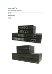
Download Asterisk Appliance™ 50 (AA50) Administrator`s Manual
Transcript
Asterisk Appliance™ 50 (AA50) Administrator’s Manual Release 1.05 Digium, Inc. 150 West Park Loop, Suite 100 Huntsville, AL 35806 United States Main Number: 1.256.428.6000 Tech Support: 1.256.428.6161 U.S. Toll Free: 1.877.546.8963 Sales: 1.256.428.6262 www.digium.com www.asterisk.org www.asterisknow.org © Digium, Inc. 2007 All rights reserved. No part of this publication may be copied, distributed, transmitted, transcribed, stored in a retrieval system, or translated into any human or computer language without the prior written permission of Digium, Inc. Digium, Inc. has made every effort to ensure that the instructions contained in this document are adequate and error free. The manufacturer will, if necessary, explain issues which may not be covered by this documentation. The manufacturer’s liability for any errors in the documents is limited to the correction of errors and the aforementioned advisory services. This document has been prepared for use by professional and properly trained personnel, and the customer assumes full responsibility when using it. Adobe and Acrobat are registered trademarks, and Acrobat Reader is a trademark of Adobe Systems Incorporated. Asterisk and Digium are registered trademarks and Asterisk Business Edition, AsteriskNOW, AsteriskGUI, and Asterisk Appliance are trademarks of Digium, Inc. Any other trademarks mentioned in the document are the property of their respective owners. Release 1.05 Digium, Inc. Page 2 Safety Certification and Agency Approvals Safety: US/CSA 60950 IEC 60950 AS/NZS 60950 EN 60950 Other: CE Mark (European Union) 2002/95/EC Restrictions on Hazardous Substances (RoHS), 2005/747/EC lead free exemption (Annex C) Telecom: FCC Part 68, TIA-968 AS/ACIF S002 TBR-21 1998 Industry Canada IC-CS-03 EMC: FCC Part 15 Class A EN55022/CISPR22 Class A EN55025 IEC 61000 AS/NZS CISPR22 Class A CNS13438 VCCI V-32005.04 Release 1.05 Digium, Inc. Page 3 Federal Communications Commission Part 68 (USA) This equipment complies with Part 68 of the FCC rules and the requirements adopted by the ACTA. On the back of the Asterisk Appliance enclosure is a label that contains, among other information, a product identifier in the format US:AAAEQ##TXXXX. If requested, this number must be provided to the telephone company. A plug and jack used to connect this equipment to the premises wiring and telephone network must comply with the applicable FCC Part 68 rules and requirements adopted by the ACTA. If the Asterisk Appliance™ causes harm to the telephone network, the telephone company may notify you in advance that temporary discontinuance of service may be required. But if advance notice is not practical, the telephone company will notify you as soon as possible. Also, you will be advised of your right to file a complaint with the FCC if you believe it is necessary. The telephone company may make changes in its facilities, equipment, operations or procedures that could affect the operation of the equipment. If this happens, the telephone company will provide advance notice in order for you to make necessary modifications to maintain uninterrupted service. If you experience problems with the Asterisk Appliance, contact Digium, Inc. (+1.256.428.6161) for repair and/or warranty information. If the equipment is causing harm to the telephone network, the telephone company may request that you disconnect the equipment until the problem is resolved. Release 1.05 Digium, Inc. Page 4 FCC Part 15 This device complies with part 15 of FCC rules. Operation is subject to the following two conditions: (1) This device may not cause harmful interference, and (2) This device must accept any interference received, including interference that may cause undesired operation. Release 1.05 Digium, Inc. Page 5 Introduction to Asterisk Appliance Documentation This manual contains product information for the Asterisk Appliance. Be sure to refer to any supplementary documents or release notes that were shipped with your equipment. The manual is organized in the following manner: Chapter/ Appendix Title Description 1 Overview Identifies the features of your unit. This chapter covers applications and uses of the Asterisk Appliance in the real world. 2 Unit Installation Provides instructions for installing the unit, acquiring correct drivers, and checking device compatibility. 3 Asterisk Configuration Provides instructions on how to configure the embedded Asterisk Business Edition through the use of the AsteriskGUI. 4 Troubleshooting Explains resolutions to common problems and frequently asked questions pertaining to the unit installation and usage. A Pin Assignments Lists the connectors and pin assignments. B Specifications Details unit specifications. C Glossary and Acronyms Defines terms related to this product. Release 1.05 Digium, Inc. Page 6 Symbol Definitions Caution statements indicate a condition where damage to the unit or its configuration could occur if operational procedures are not followed. To reduce the risk of damage or injury, follow all steps or procedures as instructed. The ESD symbol indicates electrostatic sensitive devices. Observe precautions for handling devices. Wear a properly grounded electrostatic discharge (ESD) wrist strap while handling the device. The Electrical Hazard Symbol indicates a possibility of electrical shock when operating this unit in certain situations. To reduce the risk of damage or injury, follow all steps or procedures as instructed. Release 1.05 Digium, Inc. Page 7 Important Safety Instructions User Cautions Servicing. Do not attempt to service this unit unless specifically instructed to do so. Do not attempt to remove the unit from your equipment while power is present. Refer servicing to qualified service personnel. Water and Moisture. Do not spill liquids on this unit. Do not operate this equipment in a wet environment. Heat. Do not operate or store this product near heat sources such as radiators, air ducts, areas subject to direct, intense sunlight, or other products that produce heat. Warning. Do not place anything (including paper) on top of the Asterisk Appliance. To allow proper cooling, these units must not be stacked. Caution. To reduce the risk of fire, use only No. 26 AWG or larger telecommunication wiring for network connections. Static Electricity. To reduce the risk of damaging the unit or your equipment, do not attempt to open the enclosure or gain access to areas where you are not instructed to do so. Refer servicing to qualified service personnel. Caution. This unit must be used in restricted access locations and installed in UL Listed I.T.E. only. Release 1.05 Digium, Inc. Page 8 User Cautions Emergency 911 The Asterisk Appliance is capable of forwarding arbitrary caller id strings to service providers, which in multi-office setups could simply be other Asterisk Appliances. Customers of Internet Telephony Service providers to which 911 or Emergency calls are placed should ensure their provider properly forwards the customer's accessible PSTN phone number to the emergency call handling center. Save these instructions for future reference. Release 1.05 Digium, Inc. Page 9 TABLE OF CONTENTS Chapter 1 Overview . . . . . . . . . . . . . . . . . . . . . . . . . . . . . . . . . . . . . . . . . . . . . . . 14 Features: . . . . . . . . . . . . . . . . . . . . . . . . . . . . . . . . . . . . . . . . . . . . . 15 What is Asterisk? . . . . . . . . . . . . . . . . . . . . . . . . . . . . . . . . . . . . . . .16 Chapter 2 Unit Installation . . . . . . . . . . . . . . . . . . . . . . . . . . . . . . . . . . . . . . . . . . 17 Unpacking the Unit . . . . . . . . . . . . . . . . . . . . . . . . . . . . . . . . . . . . . 18 Inspecting Your Shipment . . . . . . . . . . . . . . . . . . . . . . . . . . . . . . . . 18 Identifying Communication Ports . . . . . . . . . . . . . . . . . . . . . . . . . . 19 Understanding the LEDs . . . . . . . . . . . . . . . . . . . . . . . . . . . . . . . . .19 Using the Configuration Reset Switch . . . . . . . . . . . . . . . . . . . . . . 23 Installing the Appliance . . . . . . . . . . . . . . . . . . . . . . . . . . . . . . . . . . 24 Mounting the Asterisk Appliance . . . . . . . . . . . . . . . . . . . . . . . . . . 26 Chapter 3 Telephone System Configuration . . . . . . . . . . . . . . . . . . . . . . . . . . . 28 Log On to the Appliance . . . . . . . . . . . . . . . . . . . . . . . . . . . . . . . . . 29 Configuring Your Appliance . . . . . . . . . . . . . . . . . . . . . . . . . . . . . . 30 User Extensions . . . . . . . . . . . . . . . . . . . . . . . . . . . . . . . . . . . . . . . 32 Conferencing . . . . . . . . . . . . . . . . . . . . . . . . . . . . . . . . . . . . . . . . . 35 Voicemail . . . . . . . . . . . . . . . . . . . . . . . . . . . . . . . . . . . . . . . . . . . . 38 Calling Queues . . . . . . . . . . . . . . . . . . . . . . . . . . . . . . . . . . . . . . . .41 Adding Service Providers . . . . . . . . . . . . . . . . . . . . . . . . . . . . . . . . 45 Release 1.05 Digium, Inc. Page 10 Table Of Contents Calling Rules . . . . . . . . . . . . . . . . . . . . . . . . . . . . . . . . . . . . . . . . . . 50 Incoming Calls . . . . . . . . . . . . . . . . . . . . . . . . . . . . . . . . . . . . . . . . 53 Networking . . . . . . . . . . . . . . . . . . . . . . . . . . . . . . . . . . . . . . . . . . . 55 Voice Menus . . . . . . . . . . . . . . . . . . . . . . . . . . . . . . . . . . . . . . . . . . 58 Record a Menu . . . . . . . . . . . . . . . . . . . . . . . . . . . . . . . . . . . . . . . .64 Call Parking . . . . . . . . . . . . . . . . . . . . . . . . . . . . . . . . . . . . . . . . . .65 Ring Groups . . . . . . . . . . . . . . . . . . . . . . . . . . . . . . . . . . . . . . . . . .67 Asterisk Management Options . . . . . . . . . . . . . . . . . . . . . . . . . . . . 69 Update . . . . . . . . . . . . . . . . . . . . . . . . . . . . . . . . . . . . . . . . . . . . . . 70 Advanced Options . . . . . . . . . . . . . . . . . . . . . . . . . . . . . . . . . . . . . 71 Chapter 4 Troubleshooting . . . . . . . . . . . . . . . . . . . . . . . . . . . . . . . . . . . . . . . . . 72 Appendix A Pin Assignments . . . . . . . . . . . . . . . . . . . . . . . . . . . . . . . . . . . . . . . . . 73 Appendix B Specifications . . . . . . . . . . . . . . . . . . . . . . . . . . . . . . . . . . . . . . . . . . . 77 Appendix C Glossary and Acronyms . . . . . . . . . . . . . . . . . . . . . . . . . . . . . . . . . . . 79 Release 1.05 Digium, Inc. Page 11 List of Figures Figure 1: Figure 2: Figure 3: Figure 4: Figure 5: Figure 6: Figure 7: Figure 8: Figure 9: Figure 10: Figure 11: Figure 12: Figure 13: Figure 14: Figure 15: Figure 16: Figure 17: Figure 18: Figure 19: Figure 20: Figure 21: Figure A-1: Release 1.05 The Asterisk Appliance . . . . . . . . . . . . . . . . . . . . . . . 17 Example Asterisk Appliance Port Identification . . . .22 Asterisk Appliance Back View . . . . . . . . . . . . . . . . .23 Mounting Instructions . . . . . . . . . . . . . . . . . . . . . . . . 26 GUI Login . . . . . . . . . . . . . . . . . . . . . . . . . . . . . . . . . 29 Home Page . . . . . . . . . . . . . . . . . . . . . . . . . . . . . . . . 30 User Extensions . . . . . . . . . . . . . . . . . . . . . . . . . . . . 32 Conferencing . . . . . . . . . . . . . . . . . . . . . . . . . . . . . . 35 Voicemail . . . . . . . . . . . . . . . . . . . . . . . . . . . . . . . . . 38 Call Queues . . . . . . . . . . . . . . . . . . . . . . . . . . . . . . . 41 Service Providers . . . . . . . . . . . . . . . . . . . . . . . . . . . 45 Add New Service Provider . . . . . . . . . . . . . . . . . . . . 46 Calling Rules . . . . . . . . . . . . . . . . . . . . . . . . . . . . . . . 50 New Calling Rule . . . . . . . . . . . . . . . . . . . . . . . . . . . 51 Incoming Calls . . . . . . . . . . . . . . . . . . . . . . . . . . . . .53 Networking . . . . . . . . . . . . . . . . . . . . . . . . . . . . . . . . 55 Voice Menus . . . . . . . . . . . . . . . . . . . . . . . . . . . . . . . 58 Record Menu Prompts . . . . . . . . . . . . . . . . . . . . . . .64 Call Parking . . . . . . . . . . . . . . . . . . . . . . . . . . . . . . . 65 Ring Groups . . . . . . . . . . . . . . . . . . . . . . . . . . . . . . . 67 Update . . . . . . . . . . . . . . . . . . . . . . . . . . . . . . . . . . . 70 Back Panel Ports . . . . . . . . . . . . . . . . . . . . . . . . . . . 73 Digium, Inc. Page 12 List of Tables Table A-1: Table A-2: Table A-3: Table B-4: Release 1.05 CRAFT Port Pinout . . . . . . . . . . . . . . . . . . . . RJ11 Analog Port Connector . . . . . . . . . . . . . LAN & WAN Ethernet Port Pinouts . . . . . . . . Maximum 12V Power Consumption . . . . . . . Digium, Inc. . . . . . . 74 . . . . . . 75 . . . . . . 76 . . . . . . 78 Page 13 Chapter 1 Overview ® The Digium Asterisk Appliance 50 (AA50) is a stand alone PBX which runs a version of Asterisk. It is suitable for the desktop, or mounting in a typical network closet or restricted access location. The AA50 is ideal for small office environments or as an extension to a central Asterisk PBX. The AA50 can function not only as a PBX, but also as a voice mail server, IVR server, conferencing server, VoIP ATA, or VoIP gateway. It has eight analog ports which can be configured (via modules) as FXO or FXS ports. Additionally, the built in four port switch and WAN port allow it to also serve as a basic router. The AA50’s features are covered in depth in the following chapters. Release 1.05 Digium, Inc. Page 14 Chapter 1: Overview Features: Embedded Asterisk Business Edition™ AsteriskGUI™ Four port 10/100BaseT Ethernet switch with Auto-MDI/MDI-X capability for the four 10/100BaseT LAN ports and one 10/100baseT WAN port (both 802.3/802.3u) Up to eight analog ports supporting either FXS or FXO lines depending on product version SIP and IAX2 VoIP protocols CompactFlash interface (Type 1) suitable for standard CompactFlash cards and wireless 802.11b Configuration reset switch High performance Analog Devices Incorporated (ADI) BlackFin BF537 processor uClinux Operating System Transcoding provided on the Blackfin processor 32ms of analog port echo cancellation 8MB on board serial Flash memory 64MB 16 bit parallel SDRAM Front panel LEDs Release 1.05 Digium, Inc. Page 15 Chapter 1: Overview What is Asterisk? Asterisk is the first Open Source telephony platform. Since it runs on Linux, it inherits all of the power and stability of that operating system. The name Asterisk is derived from the all-inclusive “wildcard” symbol in UNIX. It is representative of the wide range of opportunities it opens for developers worldwide to create solutions which would otherwise be costprohibitive. Asterisk allows you to create a PBX solution that rivals the features and functionality of traditional telephony switches. Current PBX solutions are expensive and proprietary. International companies are discovering that Asterisk is cost effective, low maintenance, and flexible enough to handle all of their voice and data networking. Using the Asterisk Appliance, anyone can replace an existing small business PBX. You can also utilize the appliance as an adjunct application server for conferencing, voice mail, or IVR. Asterisk will work with most standards-based IP telephone handsets and software. Analog phones and ADSI-screen phones are also supported. Release 1.05 Digium, Inc. Page 16 Chapter 2 Unit Installation This chapter provides the following information: Unpacking the Unit on page 18 Inspecting Your Shipment on page 18 Identifying Communication Ports on page 19 Understanding the LEDs on page 19 Using the Configuration Reset Switch on page 23 Installing the Appliance on page 24 Mounting the Asterisk Appliance on page 26 Figure 1: The Asterisk Appliance Release 1.05 Digium, Inc. Page 17 Chapter 2: Unit Installation Unpacking the Unit When you unpack your unit, carefully inspect it for any damage that may have occurred in shipment. If damage is suspected, file a claim with the carrier and contact your reseller from which the unit was purchased or Digium Technical Support (+1.256.428.6161). Keep the original shipping container to use for future shipment or proof of damage during shipment. Note: Only qualified service personnel should install the unit. Users should not attempt to perform this function themselves. Inspecting Your Shipment The following items are included in shipment of the Asterisk Appliance: Asterisk Appliance 50 (AA50) Compact Flash Card Power Supply Power Cable Analog Cables (optional depending on model) CD-ROM containing manual and installation files Product Registration Card Support and Warranty Information Release 1.05 Digium, Inc. Page 18 Chapter 2: Unit Installation Identifying Communication Ports The Asterisk Appliance unit consists of up to eight RJ11 analog ports which can be configured as either FXO or FXS ports, depending on the type of modules installed in the Asterisk Appliance model. These ports provide 32ms of analog port echo cancellation. The unit is rated for a total of 8 REN across all FXS ports. Each individual port is rated for up to 3 REN @ 1500ft (450m). Four 10/100BaseT LAN ports and one 10/100BaseT WAN port provide the functionality to connect to the local network as well as allowing the Asterisk Appliance to act as a router. All the Ethernet ports support autoMDI/MDX. See Figure 2 on page 22 to locate the ports and their corresponding LEDs. Understanding the LEDs There are 15 LEDs on the front panel of the Asterisk Appliance. The eight LEDs corresponding to the analog ports on the rear panel, indicate the type of interface installed. The definition of each LED and its color representation is explained in Table 1. Release 1.05 Digium, Inc. Page 19 Chapter 2: Unit Installation Table 1: LED Definitions LED Color Description Power Blue (pulsing) On when the unit boots up after the bootload process has completed. The LED pulses at a rate which is proportional to the processor load. Compact Flash Blue (flashing) Flashes each time there is read or write activity to or from the CompactFlash card. WAN Off No line is connected or the interface is inactive. Green (flashing) Link is up at 100Mbps. LED flashes at 1/ 10 second intervals as traffic is detected. Orange (flashing) Link is up at 10Mbps. LED flashes at 1/10 second intervals as traffic is detected. Off No line is connected or the interface is inactive. Green (flashing) Link is up at 100Mbps. LED flashes at 1/ 10 second intervals as traffic is detected. Orange (flashing) Link is up at 10Mbps. LED flashes at 1/10 second intervals as traffic is detected. LAN (4 ports) Release 1.05 Digium, Inc. Page 20 Chapter 2: Unit Installation Table 1: LED Definitions LED Analog (8 ports) Release 1.05 Color Description Off No analog port is installed in the corresponding port. Green (solid) Port is configured for FXS operation and is enabled. An analog telephone may be connected to this port. Green (flashing) Telephone is ringing. Green (slow blinking) Telephone is in use. Red (solid) Port is configured for FXO operation and is enabled. A telephone line may be connected to this port. Red (flashing) Telephone line is ringing. Red (slow blinking) Telephone line is in use. Digium, Inc. Page 21 Chapter 2: Unit Installation Figure 2: Example Asterisk Appliance Port Identification Release 1.05 Digium, Inc. Page 22 Chapter 2: Unit Installation Using the Configuration Reset Switch The Configuration Reset (RST CFG) switch (rear panel) will reset current configuration to the factory defaults when pressed. The switch must be continually pressed during the boot process. This will force the unit to delete all configuration data. The administrator password will also be reset. See Figure 3 on page 23 to locate the CFG RST switch. Caution. Pressing the RST CFG switch will cause loss of all configuration settings and reset administration passwords. Power Supply LAN Craft Ports Port Configuration Analog Reset Switch Ports WAN Port Figure 3: Asterisk Appliance Back View Release 1.05 Digium, Inc. Page 23 Chapter 2: Unit Installation Installing the Appliance ® 1. If a Compact Flash card is to be used, remove the Compact Flash cover plate and insert the Compact Flash card before connecting the power supply. Caution. The Compact Flash is not hotswapable. The Compact Flash card should b e inserted before powering on the unit. Likewise, the Compact Flash should be unmounted (using the unmount command) and then power off the unit before removing the Compact Flash. 2. Attach one end of an ethernet cable to the appliance’s WAN port. Refer to Figure 3 for the WAN port location. The other end of the cable should be connected to the appropriate internet connection (will vary depending on your setup). This will connect the Asterisk Appliance to the internet. 3. Connect one end of an Ethernet cable (not included) to an Asterisk Appliance LAN port, and one end to an Ethernet connection on a computer configured to obtain an IP address automatically (DHCP). This step will connect your appliance to your computer so that you may access the Asterisk Appliance. 4. Connect the provided power cable to the power supply. You can then connect the power supply to the Appliance’s DC power connector. The Appliance will immediately power on once connected to a power source. 5. When the unit completes the boot process, the left-most eight LEDs will indicate how the analog ports are configured. Red indicates FXO, Green for FXS, and off if not installed. Release 1.05 Digium, Inc. Page 24 Chapter 2: Unit Installation 6. Connect telephones to the analog ports that are configured as FXS ports and connect phone lines to the analog ports that are configured as FXO ports. 7. Open a browser window (Firefox is recommended) and enter the IP address for the appliance. The default LAN IP address is 192.168.69.1. The default username is admin, and the default password is password. 8. You are now ready to configure your Asterisk Appliance via the GUI. Caution. This unit must be connected to the Telecommunications Network in your country using an approved line cord, e.g.: for Australia use only line cords complying with ACA Technical Standard TS008. Release 1.05 Digium, Inc. Page 25 Chapter 2: Unit Installation Mounting the Asterisk Appliance Figure 4 below illustrates the proper mounting installation options: Figure 4: Mounting Instructions Warning. Do not place anything (including paper) on top of the Asterisk Appliance. To allow proper cooling, these units must not be stacked. Release 1.05 Digium, Inc. Page 26 Chapter 2: Unit Installation Table 2: Wall Mounting Step Instructions for Wall Mounting 1 Select the area to mount the Asterisk Appliance unit (refer to Figure 4 on page 26). The unit should be mounted at or below eye level to properly view the LEDs. 2 Use the two keyed insets on the bottom of the unit to measure the exact distance between the two keyed insets. 3 Install two #8 PAN headscrews (1 1/2-inch or longer) into the desired location on the wall (approximately 7 1/2-inch apart horizontally or vertically), making sure they are level with each other. 4 Leave approximately 1/4-inch of the screw protruding from the wall to allow the head of the screws to slide into the keyed insets, mounting the unit to the wall. Release 1.05 Digium, Inc. Page 27 Chapter 3 Telephone System Configuration This chapter provides information on how to initially set up your telephone system via the AsteriskGUI. You can then refine your system by utilizing advanced configuration features. The following topics are covered: Log On to the Appliance on page 29 Configuring Your Appliance on page 30 User Extensions on page 32 Conferencing on page 35 Voicemail on page 38 Calling Queues on page 41 Adding Service Providers on page 45 Calling Rules on page 50 Incoming Calls on page 53 Networking on page 55 Asterisk Management Options on page 69 The Asterisk Appliance comes with embedded Asterisk Business Edition™. The software includes the AsteriskGUI, a web based configuration interface. The AsteriskGUI gives you the ability to set up your telephone system without the need to use command line configuration. After connecting to the Asterisk Appliance, the primary menu is displayed, giving you the ability to configure your system, as well as add features to your call system as your needs change. Release 1.05 Digium, Inc. Page 28 Chapter 3: Telephone System Configuration Log On to the Appliance Your Asterisk Appliance should already be connected to your computer, as described in the Installing the Appliance section. In the address field of a browser (Firefox is recommended), enter the URL assigned to your appliance. The default URL is http:// 192.168.69.1 The initial GUI login page is displayed. Figure 5: GUI Login To log on to the system enter the following credentials: Username: admin Password: password The first time you log on you will be prompted to change your password from the default. You will then be prompted to log on with the new password. Once the log on process is complete the AsteriskGUI home page will be displayed. Release 1.05 Digium, Inc. Page 29 Chapter 3: Telephone System Configuration Configuring Your Appliance The AsteriskGUI gives you the ability to configure the basic hardware and dial plan elements you need when initially setting up your system. You must create system users, conferencing, voice mail, etc. After logging into the AsteriskGUI, you’re presented with a variety of options on the left side of the page. Figure 6: Home Page Every page of the GUI has three columns. The column to the furthest left identifies all the elements for which you can program the Asterisk Appliance. The elements listed begin with Home and proceed down to Options. They are listed in the order of usage frequency, with each heading down the list utilizing information specified in a previous tab. For example, the users configured in the Users tab are used to assign voice mail options on the Voicemail tab and can be included in the Call Queues. Release 1.05 Digium, Inc. Page 30 Chapter 3: Telephone System Configuration Clicking any of the tabs on the left of the page opens the heading to list a brief explanation of what’s available in that section of the GUI, as well as to add the options to the center section. The middle of the GUI contains the primary content for each page. The Home page is used for log on purposes, as well as saving configuration changes, restoring the configuration defaults, and rebooting the hardware. Save Configuration - Each time you make a configuration change on a page those changes can be made active for the current session by clicking Activate Changes in the upper right corner of the page. However, to save the changes permanently, you must return to the home page and click Save Configuration. Restore Default - This button gives you the ability to restore all settings you have save to the factory default. Clicking this button will remove any setup information you have previously saved. Reboot - The Reboot button, as you may have guessed, reboots the Asterisk Appliance. The far right column of the GUI contains Tooltips. This area provides explanations for any element of the GUI. To see a brief description of any tab on the left, or of some menu elements in the center section, just mouse over the item. The Tooltips section of the page will immediately populate with a definition of the heading. Above the tooltips section you will see the Activate Changes and Logout buttons. These buttons appear in the upper right corner of every page. Click Activate Changes to activate changes you have made on a page so that you can utilize the changes. As noted above, these changes will not become permanent until you have clicked Save Configuration on the home page. Click Logout on any page to exit the Asterisk Appliance interface. Release 1.05 Digium, Inc. Page 31 Chapter 3: Telephone System Configuration User Extensions Click the User Extensions tab and you'll see the extensions you created in the initial setup process. Figure 7: User Extensions Release 1.05 Digium, Inc. Page 32 Chapter 3: Telephone System Configuration The following information comprises a user extension definition: Extension - The extension assigned to the defined user. Name - The first and last name of the individual assigned to this extension. The name can also be that of a department, such as Sales or Support, for example. This is important because the Dial By Name Directory function of Asterisk uses this information to route calls. Password - The password used to access voicemail for the specified extension. E-mail Address - Voice mails received by this extension can be sent as audio file attachments e-mailed to a specific address. Caller ID - Identifies the Caller ID presented when the listed extension dials out. Analog Phone - A drop-down menu is available to identify the analog phone port which this extension will access. If more than one phone is connected to your Asterisk Appliance you will need to confirm the port number listed on the back of the appliance. Dial Plan - This option references the Calling Rules option on the left tool bar. Based on the calling rules you’ve created, you can restrict the outbound dialing of this extension to local calls, emergency calls, and standard long-distance calls for North America. This option also possibly allows blocking or allowing international (011 prefix dialed) calls. Phone Serial - The Phone Serial field is used to specify the MAC address of the SIP phone connected to the port specified above. The MAC address associates the phone with this extension and enables the synchronization of provisioning information. Release 1.05 Digium, Inc. Page 33 Chapter 3: Telephone System Configuration There are also several advanced extension options available.The advanced options establish the connections from the listed extension to other systems within the Asterisk server. These systems include the following: Voicemail - Builds a voice mail box for the extension that can be reached by dialing the Check Voicemail extension. The Voicemail extension can be configured. The current default is 6050. In Directory listing - Asterisk establishes a directory of all extensions so that inbound callers can reach someone in your office by dialing the first few digits of the person’s first or last name. The company directory includes only the name of the extension if this option is checked. SIP - Identifies whether the extension sends and receives calls using the VoIP protocol SIP. IAX - Identifies whether the extension sends and receives calls using the VoIP protocol IAX. CTI - Selecting this option (Computer Telephony Integration) allows the user to connect applications to the Asterisk Management Interface. Call Waiting - If call waiting is not enabled, the extension accepts only one call before it is identified as busy. 3-Way Calling - Allows the extension to receive a call and then dial out to another phone number to conference with the inbound call and the recipient of the outbound call. Is Agent - Call queuing is made up of a bank of agents who receive calls. An extension listed as Is Agent can be added to queues from the CallQueues option on the left toolbar. To add new extensions, select New Entry in the area under Extensions and then click New. The system defaults to four-digit extensions, beginning with the number 6000. Release 1.05 Digium, Inc. Page 34 Chapter 3: Telephone System Configuration Conferencing Every company reaches the point of needing more people on a phone call than it can effectively include through three-way calling. Asterisk conference bridges allow you to include more people as well as project a professional image. Figure 8: Conferencing Release 1.05 Digium, Inc. Page 35 Chapter 3: Telephone System Configuration The configuration of the conference bridge and standard features is very straightforward. Select the New Entry option in the Extensions window and click New to design a conference bridge. The GUI auto-populates the extension with the next available extension in sequence, but you can always change it to any extension number you want. After establishing the extension for the bridge, you need to specify the password settings for the conference. Assign the PIN Code used by participants to enter the conference as well as the Administrator PIN Code used by the moderator of the conference to open the conference bridge. Now that you have established the conference bridge extension and password codes, you can set your conference room options. The next three options are hospitality features which allow the caller to feel more welcome, as follows: Play hold music for first caller - Checking this option makes music play for the first caller entering a conference until another caller joins. Some people don’t like sitting in a quiet room — even a virtual room —alone, and this feature prevents anyone from being in that position. Enable caller menu - This feature allows callers to access the Conference Bridge Menu by pressing the asterisk (*) key. Announce callers - All new callers to a conference are identified when they arrive when this feature is selected. The remaining configuration features provide some great functionality and heightened control over your conferences. If you are bringing together sales teams or vendors on a conference, it is preferable to keep them from chatting amongst themselves before the host arrives. These features allow you to handle the following requirements: Release 1.05 Digium, Inc. Page 36 Chapter 3: Telephone System Configuration Quiet Mode - You may choose this feature for a conference bridge with room override because it allows all users on the bridge to have listen-only access to the conference. Establishing two access points, with one group of people using the main extension while the other remains in quiet mode allows a controlled environment in which to deliver information while the second group listens. Wait for Marked User - This is a feature that keeps all participants in quiet mode until a special participant, using a unique extension, arrives. Only after the marked user arrives is the audio activated so that all of the participants can speak to each other. Set Marked User - This option works in conjunction with the Wait for Marked User feature. Checking Set Marked User makes the individual arriving from this extension the Marked User. If the CEO of the company, for example, doesn’t want anyone chatting in the conference bridge until he or she arrives, these options are set to keep everything quiet. The main conference extension of 6003 is configured with Wait for Marked User selected. Everyone in the conference arriving from extension 6003 remains silent until the CEO arrives. Release 1.05 Digium, Inc. Page 37 Chapter 3: Telephone System Configuration Voicemail Voicemail is an option available for every extension in Asterisk. The relationship between the extension and the voice mail is established in the User Extension section of the GUI. That section covers only the relationship between the extension and the voice mail but doesn’t identify the parameters of the voice mail service itself. Figure 9: Voicemail The Voicemail Configuration page displays all the extensions to the left, including voice mail. Standard configuration information is also present, allowing you to confirm the extension used to check messages, as well as general parameters such as the following: Release 1.05 Digium, Inc. Page 38 Chapter 3: Telephone System Configuration Extension for Checking Messages - This option defines the extension which Users call in order to access their voicemail account. Attach Recordings to E-Mail - This option is used to choose whether voicemails are sent to the selected users e-mail address as attachments. Click the check box to enable this option. Max Greeting (Seconds) - With this option, you specify the maximum amount of time available to record your voicemail greeting. Dial “0” for Operator - Callers who are sent to voice mail can press “0” for the operator and be transferred either during the voice mail salutation, or after recording the message. If this option is not enabled, a caller’s pressing “0” will be ignored. There are several options that can be specified to define the voicemail message in the system. Message Format - This option gives you the ability to choose the format in which messages are delivered by e-mail. Maximum Messages per Folder - The maximum number of messages per voice mail box is set here. Maximum Message Time - The maximum duration of a message left by a caller is set here. Minimum Message Time - The minimum duration of a message is dictated here. Any message left that’s under the listed duration is discarded and isn’t processed or retrievable. Release 1.05 Digium, Inc. Page 39 Chapter 3: Telephone System Configuration There are several playback options that can be specified. Send Messages by E-Mail Only - You can choose to have e-mail be your only means of notification of voice mails left for you by this option. Say Message Caller-ID - The Say Message Caller ID option reads the caller ID before the voice mail message is played. Say Message Duration - This option identifies exactly how long the message lasted. Play Envelope - The envelope provides the date, time, and caller ID related to a voice mail. Allow Users to Review - This option provides incoming callers the option to review their message before it is saved and can be played back by the owner of the voice mail extension. Standard options are presented to you, allowing you to discard the message or re-record it if you aren’t happy with it. Release 1.05 Digium, Inc. Page 40 Chapter 3: Telephone System Configuration Calling Queues A call queue lines up callers and allows them to wait to speak to any group of employees taking a high volume of calls. The feature allows you to speak to more people rather than send callers back to voice mail to leave a message and receive a call back when time permits. Asterisk identifies which extensions under the Users tab are capable of belonging to a call queue by whether the Is Agent option is selected. The Is Agent indicates that the user is available to answer customer calls. If a check mark does not appear next to Is Agent, that extension won’t appear in the list of agents in the configuration for this option. The following illustration shows the Queue Extension Configuration window displaying the available options. Figure 10: Call Queues Release 1.05 Digium, Inc. Page 41 Chapter 3: Telephone System Configuration The Queues section lists the existing queues. Existing queues are in black. To create a new queue, click New below the queue listing. Use the following steps to create a queue. Keep in mind the purpose of the queue and how it should operate. Creating a Queue 1. The extension for the queue will automatically populate in the Queue field with the next available extension. If you want the number to be something other than the automatically chosen one, enter it in the Queue field. 2. Next, give the queue a name that will be meaningful. The queue will be referenced by this name, so be sure to make it sufficiently descriptive as well. For example, “Technical Support” for the technical support queue, “Sales”, and so on. 3. You now should choose the strategy used in your queue call logic. Using the Strategy drop-down list, choose one of the following options for routing calls: – Ring All - Rings every agent who isn’t on an active call when a new call arrives. The first agent to answer the call receives it. – Round Robin - Every available agent receives a call in turn, akin to how cards are dealt in a poker game. – Least Recent - The agent who has been without a call the longest receives the next call. – Fewest Calls - The agent who has handled the fewest calls receives the next incoming call. – Random - Goes by the luck of the draw; any agent can receive the next incoming call. Release 1.05 Digium, Inc. Page 42 Chapter 3: Telephone System Configuration – RrMemory - This option is Round Robin with Memory. It’s similar to Round Robin, but smarter — it remembers over the course of days, weeks, or years which agent received the last call so that it can commence with the next agent in sequence when calls begin again. 4. The Agents box lists all Users that are designated as an agent that can receive calls as part of a call queue. All users listed have the Is Agent checkbox selected on their user profile. Many Users may be listed as potential agents, but some may be assigned to a sales queue and some for a service queue. This box lists all agents and enables you to choose which users you assign to the queue. The options available in the Queue Options section control the timing and managing of the calls as well as the agents. You may not want to work with these finer points of call queuing until after your call queue has been working for a while and you have an idea of call volume and the turnover of calls by each agent. Here’s a list of the available options: Timeout - The default for this option is 15, representing 15 seconds that an agent’s phone will ring before the call is forwarded on to another agent. Wrapup Time - This is a buffer of time allowing your agents to finish work on one call and remain unavailable in the queue. The default on this option is 0 seconds, providing no buffer time for your agents and allowing the next call to ring through immediately after a call is complete. Max Len - This option sets the maximum number of callers allowed in the queue before they are sent to voice mail or receive a busy signal. The default is “0,” which allows for an unlimited number of calls in queue before they are sent elsewhere. Release 1.05 Digium, Inc. Page 43 Chapter 3: Telephone System Configuration Music on Hold - This option gives you the ability to select the music played while a call is on hold. Auto Fill - This option is enabled by default and allows multiple calls that arrive at the same time to be immediately forwarded on to agents. Auto Pause - If an agent fails to answer a call, this option temporarily postpones sending calls to that agent. Join Empty - This option allows callers to enter a queue even if no agents are logged into it. If this option is not checked, callers cannot enter a queue until at least one agent is present. Leave When Empty - This option mirrors the Join Empty, but it represents a queue in which agents had been logged in but are now gone. At 5:00 pm, when your employees go home, you can program the queue to shut down when the agents log out. The existing callers in queue are forced to exit, and no new callers are granted access to the queue. Report Hold Time - The Report Hold Time tells the agent how long the call was holding in queue before it was sent to the agent. If the hold time was short, the agent will probably be happy to accept the call. If the hold time was 10, 15, or 20 minutes, the agent might want to brace for a frustrated customer, but at least the agent isn’t overwhelmed. Release 1.05 Digium, Inc. Page 44 Chapter 3: Telephone System Configuration Adding Service Providers Even though you are using Asterisk on the Asterisk Appliance, you must register with a service provider in order to connect to the Public Switched Telephone Network (PSTN). Access to the PSTN gives you the ability to place calls to telephone numbers no matter how they connect to the PSTN (VoIP or standard analog system). Asterisk generically identifies the carriers used to reach your local phone carrier, long-distance carrier, or VoIP provider as service providers. The service providers may use analog lines for your local carrier or IP connections for your VoIP carriers. Figure 11: Service Providers Release 1.05 Digium, Inc. Page 45 Chapter 3: Telephone System Configuration There are three service provider categories: Analog, VoIP, and Custom VoIP. If you have not yet added a service provider, a message stating that you have not added a provide will be displayed in the Service Providers window. To add a new provider, click Add Service Provider. The Add Service Provider dialog box will be displayed similar to the following illustration. Figure 12: Add New Service Provider Release 1.05 Digium, Inc. Page 46 Chapter 3: Telephone System Configuration Select the Provider Type depending on your needs. If you wish to use a combination of both analog and VoIP, you will need to add a service provider definition for both. Analog - Select the Analog radial button to define the analog ports you have access to as a service provider. This will give you the ability to place calls through the Asterisk Appliance utilizing analog lines. The analog ports available will be displayed when you select this option. Choose one or more analog ports by selecting their associated checkbox. You will not be able to create an analog service provider if you do not have any analog ports available. VoIP - The appliance comes pre-loaded with a selection of certified VoIP service providers. If you are already a VoIP provider customer, select the provider from the list and input your user name and password. If you are a new customer, click on the provider logo to establish a new account. Asterisk will confirm your account when you click the Save button. Custom VoIP - The Custom VoIP option allows you to create a custom VoIP definition. To create the custom VoIP provider definition you will need to complete the following Custom VoIP fields: – Comment - The comment field should be used as the name of the custom VoIP definition. – Protocol - Specify either a IAX or SIP protocol. – Register - Click the Register checkbox if you need to register your IP address with your service provider. Registering is not required for all providers. – Host - The IP address of your service provider. – Username - The user name associated with your provider account. – Password - The password associated with your provider account. Release 1.05 Digium, Inc. Page 47 Chapter 3: Telephone System Configuration Click Save to retain your Custom VoIP definition, or Cancel to discard your changes. Once you have added a service provider it will appear on the list of providers on the Service Providers page. There is an Options drop-down list associated with each Service Provider listing. The Options drop-down list allows you to edit or delete the Service Provider definition, as well as further refine the definition by choosing several advance options. Select either Codecs or Advanced to further refine the definition. Codecs - Codecs provide the ability for your voice to be converted to a digital signal and transmitted across the Internet. The quality of your call can be affected by the choice you make. The codecs available to you will depend on what is supported by the service provider you choose. All available codecs are allowed by default. Select a codec and transfer it to the Disallowed list if you do not want to use that codec. Select the Disallow All checkbox if you do not want to use any of the listed codecs. Click Update to retain your changes, or Cancel to discard them. Advanced - The following advanced options are available to further refine your service provider definition. – Trunkname - Specify a trunk name if you want to refer to the service provider definition as something other than specified in Comment. – Insecure - This option specifies how connections to a service provider (host) should be handled. Valid options are very|yes|no|invite|port. The default is no (authenticate all connections). Release 1.05 Digium, Inc. Page 48 Chapter 3: Telephone System Configuration – Port - The register request is sent through the port specified here to – – – – the service provider (host). Defaults to 5060. Caller ID - The caller ID will be set to the value specified in this field. Fromdomain - Sets default From: domain in SIP messages when acting as a SIP ua (client). Fromuser - Sets default From: user in SIP messages when acting as a SIP ua (client). Contact - Specifies a primary extension for call routing. Click Update to retain your changes, or Cancel to discard them. Click Activate Changes in the upper right corner of the page to make your changes immediately available. You can then test your changes to insure that they work. If you are happy with the results, return to the Home page and click Save Configuration to make the changes permanent. Release 1.05 Digium, Inc. Page 49 Chapter 3: Telephone System Configuration Calling Rules The Calling Rules tab on the left toolbar allows you to use basic pattern matching to differentiate outbound calls and route them accordingly. The tab displays a rundown of every calling rule established and the service providers assigned. Figure 13: Calling Rules The Calling Rules menu shows every rule name established, a brief description of the rule name, as well as the service provider used to complete the specific type of call. Release 1.05 Digium, Inc. Page 50 Chapter 3: Telephone System Configuration Click on Add a Calling Rule to define a new calling rule. The following dialog will be displayed. Figure 14: New Calling Rule A calling rule is comprised of the following items: Rule Name - Choose a name that describes the type of rule you are creating. Place this Call Through - Select a service provider through which the call should be made. Dialing Rules - The Dialing Rule gives you the ability to use basic pattern matching to differentiate calls and route them accordingly. For instance, if a number begins with 9256, and is followed by 7 or more digits, that would define a call within the state of Alabama. If a call began with 9 followed by 7 digits, it would be a local call that probably didn’t require a long distance charge. Instead of adding a rule for every extension or phone number you call, specify the pattern in this rule similar to the example. Release 1.05 Digium, Inc. Page 51 Chapter 3: Telephone System Configuration Strip - This option gives you the opportunity to remove specified digits from the call being dialed and replace them with the digits needed to make the call. You can also Prepend digits to the beginning. Note: You can call international destinations from North America without dialing an 011 prefix. Using a Calling Rule that restricts 011 calling prevents the extension from reaching Africa, Europe, Asia, Oceania, and South and Central America. This won’t block all calls outside the United States however. Canada, the U.S. Virgin Islands, Guam, Saipan, and Puerto Rico, as well as a handful of Caribbean countries, are all a part of the North American Dialing plan and can be reached by dialing 1 + the area code and a seven-digit phone number. If you want to block these, it may be best to block all long-distance calls from the extension. Once you have completed the calling rule definition click Save to accept the rule or Cancel to abandon your changes. Click Activate Changes in the upper right corner of the page to make your changes immediately available. You can then test your changes to insure that they work. If you are happy with the results, return to the Home page and click Save Configuration to make the changes permanent. The default dial plan, the collection of your calling rules, is DialPlan1. You can create more than one dial plan, especially if you want to have different dial plans for different user extensions. Click New at the top of the Calling Rules page and create a new dial plan name. You can then add calling rules for that dial plan definition. Release 1.05 Digium, Inc. Page 52 Chapter 3: Telephone System Configuration Incoming Calls The same pattern-matching logic used for processing outbound calls can also be employed for inbound calls. The two defaults define routing based on whether an incoming call matches or doesn’t match a pattern you define. Figure 15: Incoming Calls Some example incoming rules are show in the figure above. Click Add a Incoming Rule to create a new incoming rule. There are only a few options you will need to define. Release 1.05 Digium, Inc. Page 53 Chapter 3: Telephone System Configuration Route - Make a selection from the drop-down list to choose how the calls will be routed. You can select from All Unmatched Calls or Calls Which Match. From Provider - Select from the list of providers which you previously defined. To Extension - The previously defined extension which should receive the call. Once you have completed the definition of your incoming call rules, click Save. Click Activate Changes to test the functionality of your new rules. Click Save Configuration on the Home page if the rules work according to your needs. Release 1.05 Digium, Inc. Page 54 Chapter 3: Telephone System Configuration Networking The Networking page is used to configure your general network settings, as well as your Wide Area Network (WAN) and local network (LAN) settings. Figure 16: Networking Release 1.05 Digium, Inc. Page 55 Chapter 3: Telephone System Configuration The General tab, which is the default selection on the Networking page, is used to specify the following settings: Hostname - The hostname assigned to the Asterisk Appliance. This name will be used to identify the appliance on your network. NTP Server - This field gives you the ability to specify the URL of an NTP server. This is useful if you wish to regularly synchronize the appliance time setting with that of an NTP server. SSH - Select the SSH checkbox to activate the SSH server on the Appliance. The default root password is digium. Enabling this option will cause your unit to provide SSH access on both WAN and LAN interfaces, which can pose a security risk. URL for Auto-Provisioning - The URL specified in this field is used to enable auto-provisioning for Polycom phones. The default for this field is http://192.168.69.1/phoneprov. The WAN tab is used to specify the settings which will enable connection to the Internet, or to an internal, private network. DHCP - The DHCP setting enables the automatic assignment of an IP address to the Asterisk Appliance. This checkbox is selected by default. Enable GUI on WAN Interface - Select this checkbox only if you are certain you want to enable access to the Asterisk Appliance GUI via the WAN interface. This option is disabled by default as it can pose a security risk. If you have difficulty obtaining an IP address dynamically, deselect the DHCP checkbox and specify the IP address, Subnet, Gateway, and DNS settings. This information should be available from your company network administrator or Internet Service Provider (ISP). Release 1.05 Digium, Inc. Page 56 Chapter 3: Telephone System Configuration The LAN tab is used to specify the settings for your local network. A local network is usually a smaller network which is part of a WAN. The information specified here is used to access your Asterisk Appliance. The default IP address specified, 192.168.69.1, is used to access the AsteriskGUI. You can change this address to an IP address specified in the IP start and end ranges. In most cases, the default should be used. The Timezone tab is used to specify the default timezone for your appliance. You must load the time zone file from the cd which came with your Asterisk Appliance. To load the time zone file, click Browse and then browse to the file on the cd. The time zone files are located in the timezone/zoneinfo section of the cd sent with your Asterisk Appliance. Select the appropriate file (i.e. timezone/zoneinfo/America/Chicago for Central time) on the cd and then click Upload. The time zone file will be uploaded to your appliance and will be listed on the Timezone tab page. Click Set as Default to set the set the time zone as your default time zone. You will need to restart your appliance in order to complete setting the time zone as your default. Click Home to return to the home page. Click Save Configuration first to insure that all of your changes have been saved. Then click Reboot to restart the appliance. Note: The time zone files are named after cities that adhere to the time zone you need. Click Activate Changes in the upper right corner of the page to make your changes immediately available. You can then test your changes to insure that they work. If you are happy with the results, return to the Home page and click Save Configuration to make the changes permanent. Release 1.05 Digium, Inc. Page 57 Chapter 3: Telephone System Configuration Voice Menus A valuable feature of Asterisk is the ability to create Interactive Voice Response (IVR) or voice menus. Voice menus are designed to allow for more efficient routing of calls from incoming callers. The menus provide a caller with specific instructions, receive responses from the caller, and process those responses into an action. Each Appliance ships with a default voice menu already created. To better understand the creation and operation of these menus, we will examine the default one. Figure 17: Voice Menus Voice menus are constructed depending on your needs. Just like your business you need to create the solution best suited to your customers. The best way to understand how a voice menu is constructed is to examine the default “Welcome” menu provided with the Asterisk Release 1.05 Digium, Inc. Page 58 Chapter 3: Telephone System Configuration Appliance. Click Voice Menus - Welcome in the Voice Menus list. The options for the welcome menu are displayed similar to the example shown in the above illustration. The Welcome menu consists of the following steps: Answer the Call Wait ‘1’ Sec Play ‘thank-you-for-calling & Listen for KeyPress Play ‘if-u-know-ext-dial’ & Listen for KeyPress Play ‘otherwise’ & Listen for KeyPress Play ‘to-reach-operator’ & Listen for KeyPress Play ‘pls-hold-while-try’ & Listen for KeyPress WaitExten ‘6’ Sec In the example, when a caller dials your company number ending in 7000, the call is answered, and after a pause of one second the caller is greeted in the following manner: “Thank you for calling. If you know your party’s extension, please dial it now. Otherwise to reach an operator please dial 0.” If the caller tries an extension, the menu will respond with “Please wait while I try that extension.” If no action is taken by the caller, the menu will repeat after 6 seconds. This is an example of a basic voice menu. In the example, each action is a step chosen from the list of available menu options. The available menu options are as follows: Release 1.05 Digium, Inc. Page 59 Chapter 3: Telephone System Configuration Answer - This step is automatically added when creating a new menu. This step answers the incoming call. Authenticate - The Authenticate step is used to restrict access one or more areas of your system. This is useful when one wants users to have to enter a PIN code in order to proceed to a particular part of the current menu, to a different menu, or to ring an extension. Background - This step is used to play an audio file in the background while waiting for the caller to enter an extension or number. Playback is terminated once the user begins to enter an extension. To select a file to play, click and hold in the field next to the Background choice to scroll through a list of pre-recorded sound files. In the example above, “Play ‘otherwise’ & Listen for KeyPress” is an example of using the Background option. Busytone - The Busytone option should be selected if there is a step in the process in which you want to play a busy signal to the caller. For instance if the call is over. Congestion - The Congestion option is similar to the Busytone option. A congestion tone will be played to the caller, should be selected if there is a step in the process in which you want to play a busy signal to the caller. For instance if the call is over. Digit Timeout - The Digit Timeout option is used to set the maximum amount of time allowed between key presses. If a full extension is not entered in the specified time, the entry will be considered invalid. A field for entering the number of seconds before timeout appears next to the option. Release 1.05 Digium, Inc. Page 60 Chapter 3: Telephone System Configuration DISA - The DISA option allows callers from outside the system to get access an internal dial tone and place calls from within your internal system. A passcode is required. Note: Use caution when choosing this option. This option can pose a security risk. Response Timeout - If a caller does not enter a response with the time specified in this field, the call will terminate. This step could be put at the end of a series of menu choices. Playback - The Playback option is similar to the Background option because it will play a sound file you select. However, this option does not listen for a KeyPress event, and will move on to the next step in your list. Wait - The Wait option pauses the execution of steps in the voice menu list for the number of seconds you specify. WaitExten - The WaitExten option is specified to give a caller a specified amount of time to enter an extension. Goto Menu - The Goto Menu option sends a caller to one of the voice menus that you specify. Goto Directory - The Goto Directory option sends a caller to the system phone directory. This gives the user the chance to select a user name from the directory if the extension is unknown. Goto Extension - The Goto Extension option sends a caller to a specified extension. Select the extension from the available list. Dial RingGroup - This option will dial a specified RingGroup. For example, if your menu says “Press 1 for Technical Support”, the Technical Support ring group will be dialed. Hangup - The Hangup option terminates the call. Release 1.05 Digium, Inc. Page 61 Chapter 3: Telephone System Configuration Creating a Voice Menu Use the following procedure as a guide to creating a voice menu. 1. On the Voice Menu page, click New to create a new voice menu. 2. Specify a Name and an Extension. The extension will be the direct dial to the voice menu. 3. Specify the Steps of your voice menu using the welcome menu example and step descriptions as guides. 4. Select the Dial Other Extensions checkbox if you want to give a user the ability to break out of the menu selections and dial an extension within your system. Warning: The Dial Other Extensions option is important. This option allows an inbound caller to break out of the listed Keypress Events and dial another extension. A malicious person may be able to hack through your Asterisk implementation to find an outside dial tone and use it for fraud. Any extensions that are known to the public should be completely handled by the Keypress Events; callers should not be allowed to dial other extensions. Sticking to this policy protects your Asterisk system from being compromised. Release 1.05 Digium, Inc. Page 62 Chapter 3: Telephone System Configuration 5. Specify the Keypress Event actions for digits 0-9 as well as *, #, t, and i. The options available for a Keypress Event are: Disabled - The associated key is not enabled. Goto Menu - Pressing a key with this option will send the caller to a specified menu. Goto Extension - Pressing a key with this option will send the caller to a specified extension. Custom Hangup - Pressing a key with this option will terminate the call. Play Invalid - Pressing a key with this option will tell the caller that they have made an invalid entry. Both the t key and i key should be used for specific actions. The action associated with the t key should be the desired action if a user response has timed-out. The action associated with the i key should be the desired action if a user makes an invalid entry. 6. Once you have constructed your voice menu, click Save. You can then click Activate Changes to add the voice menu to your current configuration. If you are happy with the voice menu, click Save Configuration on the Home page. Release 1.05 Digium, Inc. Page 63 Chapter 3: Telephone System Configuration Record a Menu In the event that one wants to record custom menu prompts for Asterisk, which can be used in a voice menu, the Record a Menu tab may be used. A list of previously recorded menus is displayed. Here, the user may modify several options: Record Again - Clicking this button allows the user to make another attempt at recording and replacing an existing custom sound file. Play - Clicking this button brings up a dialog entry box to allow the input of an extension that Asterisk will dial and play the prompt over. Delete - Clicking this button will delete the selected prompt. There are three options under "Record a new voice menu": Figure 18: Record Menu Prompts File Name - This text entry box specifies the saved name of the file that is to be recorded. Extension Used for Recording - This drop-down select box allows the user to choose which extension Asterisk will dial to wait for the user to speak the prompt. Record - Clicking this button causes Asterisk to launch the call that will record a file. Release 1.05 Digium, Inc. Page 64 Chapter 3: Telephone System Configuration Call Parking Call parking is an Asterisk feature which allows a user to place a call on hold so that it can be taken off hold from another extension. The Call Parking page gives you the ability to define the call parking options which will enable use of this feature. Figure 19: Call Parking The following options must be configured to enable call parking. Extension to Dial for Parking Calls - Specify the extension to call when transferring a call to hold or the “parking lot”. What Extensions to Park Calls On - The extensions specified here will be the “parking lot” designations for the calls you place on hold. The call on hold will be retrieved by dialing one of these extensions. Release 1.05 Digium, Inc. Page 65 Chapter 3: Telephone System Configuration Number of Seconds a Call Can Be Parked - The number of seconds a call can be placed on hold. After the time has elapsed the call will ring the originating extension. Parking a Call You can park a call using either an analog or VoIP phone. To use an analog phone, hit the flash button, or quickly click the hook switch, wait for a dial tone, then dial the extension (700). With a VoIP phone, initiate the transfer, dial the call parking extension (i.e. 700), then complete the transfer (such as by click send). The method using a VoIP phone will vary depending on the phone. At this point, the appliance will prompt you with a number. The number it prompts you with is the number from the pool specified. This is the number that can be entered to retrieve the call. To retrieve the call, pickup a phone, and dial the parking number specified by the appliance. The amount of time that the call remains parked is determined by the number of seconds specified. If the call is not retrieved in this time, the call will be redirected to the user that originally parked the call. Note: In order to properly park a call, you must use attended transfer functions. Using a blind transfer function will not provide the parking number to the person parking the call. This makes recovery of the call impossible, except for the fall through timeout. Release 1.05 Digium, Inc. Page 66 Chapter 3: Telephone System Configuration Ring Groups Ring groups allow a group of phones, or devices, to ring simultaneously or in sequence (ring order). This provides the opportunity for multiple people to answer a call (ring all) or one person can answer a call from any phone. The Asterisk Appliance does not come with a default ring group. To create a new ring group click New Ring Group at the top of the Ring Groups page. Figure 20: Ring Groups Note: You will not be able to define a ring group without user extensions or trunks defined. Release 1.05 Digium, Inc. Page 67 Chapter 3: Telephone System Configuration To create a ring group, use the following procedure. 1. Define the Name of the group. The name can be any mnemonic such as Sales or Technical Support. 2. Choose a ring group strategy from the Strategy drop-down list. You can choose either Ring All which will ring all phones in the defined group simultaneously, or Ring Order which will ring phones in sequence determined by the order of the users or trunks in the group. 3. Choose the members of the ring group from the Available Channels list. Click on a user extension or trunk, and then click the arrow pointed at the Ring Group Members list to transfer. Select a user extension or trunk in the Ring Group Members list to and then click the arrow pointing toward Available Channels to transfer the selected item back to the list. Click the double arrow symbol to transfer all group members back to the Available Channels list. 4. Specify an extension to associate with the ring group. This is the extension that can be dialed to ring all members of the group simultaneously or in order of listing. 5. Specify the number of seconds that each phone (or all phones) should ring before either ringing the next phone in order. 6. Lastly, determine what action you want the system to take if no one answers the call. You can either direct the call to the voicemail of the first user, go to an IVR menu, or end the call. Release 1.05 Digium, Inc. Page 68 Chapter 3: Telephone System Configuration Asterisk Management Options There are several administrative tabs which are used to manage your Asterisk server and the GUI interface. You may use them often or not at all, depending on how much interaction you have with your Asterisk implementation. The management selections are as follows: Active Channels - This tab provides you with a remote view of the active calls and devices. It displays a snapshot of the activity of the server and can be refreshed to view the progression of calls. System Info - The general system information of the Asterisk Appliance is displayed from this tab, as well as tabs for your ifconfig, disk partitioning resources, and IP logs. Backup - This is a housekeeping tab which allows you to back up Asterisk to preserve your changes. To create a backup, click Take a Backup and then specify a file name (i.e. the backup date). Options - The options tab provides several options which allow you to change the password for your AsteriskGUI logon, modify local extension and agent settings, as well as utilize the Setup Wizard. The Advanced/Basic tab allows you to enable or disable advanced options. The basic options are displayed by default. Please refer to the Advanced Options section for a description of the advanced options. Release 1.05 Digium, Inc. Page 69 Chapter 3: Telephone System Configuration Update The Updates tab provides an interface for downloading or uploading newer firmware images to the Appliance. Customers with an active Service Subscription may visit the Digium.com website to register their appliance, activate their Service Subscription, and download software updates for the appliance. The Updates tab provides two interfaces for putting a new image on the appliance. Figure 21: Update The first section provides the user the ability to specify a location from which the Appliance will connect and download the updated software. The user may specify an absolute HTTP location such as: http://company.com/downloads/software.img or the address and filename on an accessible TFTP server. Release 1.05 Digium, Inc. Page 70 Chapter 3: Telephone System Configuration The second section provides a web-based interface for uploading software updates. Here, the user may click the "Browse" button, select a local copy of the new software, and click the "Upload" button. Advanced Options There are several advanced options available from the Options page which give advanced users with a background in Asterisk the ability to refine the Asterisk Appliance configuration. Note: Any changes made on the advanced options pages must be activated by clicking Activate Changes at the top of the GUI. To permanently save the changes, click Save Configuration on the Home page. File Editor - The File Editor page lets you edit any Asterisk configuration file within the GUI, as well as create a new configuration file. Asterisk CLI - The Asterisk CLI is a command line interface which can be used for issuing any Asterisk command or series of commands. The results of the commands are displayed in the pane above the command line field. Enter Help in the command line field for a list of commands. VM Email Settings - Asterisk can be configured to send voicemail files to a user extension via e-mail. The VM Email Settings page give you the ability to modify the e-mail template. Global SIP Settings - The SIP configuration settings can be enabled or disabled from this page. Global IAX Settings - The IAX configuration settings can be enabled or disabled from this page. Release 1.05 Digium, Inc. Page 71 Chapter 4 Troubleshooting Where can I find answers to additional questions? There are several places to inquire for more information about Asterisk Digium products: 1. Digium Technical Support (+1.256.428.6161), or Toll Free in the U.S. (1.877.546.8963), is available 7am-7pm Central Time (GMT -6), Monday - Friday. 2. Asterisk users mailing list (asterisk.org/lists.digium.com). 3. IRC channel #asterisk on (irc.freenode.net). Maintenance Support Program Digium is dedicated to supporting your Asterisk system by offering full technical support through our Maintenance Support Program. The Maintenance Support Program covers all Digium hardware and the complete Asterisk software suite. Through this program, you can be at ease knowing that your business will always have access to the Asterisk experts. To obtain a quote for maintenance please contact Asterisk Express sales at +1.256.428.6060 or [email protected]. Release 1.05 Digium, Inc. Page 72 Appendix A Pin Assignments This appendix provides pin assignments for the Asterisk Appliance unit. LAN Ports Craft Port WAN Port Analog Ports Figure A-1: Back Panel Ports All eight analog ports on the Asterisk Appliance are 8-pin RJ11 ports. The pin assignments are identified in Table A-2. Release 1.05 Digium, Inc. Page 73 Appendix A: Pin Assignments Table A-1: CRAFT Port Pinout Diagram Pin 1 Pin 8 Pin Description 1 Ground (Connect to DB9 pin 5) 2 Unused (Leave Open) 3 Primary RxD (To Appliance) (Connect to DB9 Pin 3) 4 Open 5 Tx (From Appliance) (Connect to DB 9 Pin 2) 6 CTS (To Appliance) (Connect to DB9 Pin 7) 7 Open 8 RTS (From Appliance) (Connect to DB9 Pin 8) Note: The secondary serial port is not wired in the craft port adapter that may be supplied with the unit. Release 1.05 Digium, Inc. Page 74 Appendix A: Pin Assignments Table A-2: RJ11 Analog Port Connector Diagram Pin 1 Release 1.05 Pin Description 1 Unused 2 Unused 3 Tip 4 Ring 5 Unused 6 Unused Pin 6 Digium, Inc. Page 75 Appendix A: Pin Assignments Table A-3: LAN & WAN Ethernet Port Pinouts Diagram Pin 1 Release 1.05 Pin 8 Pin Description 1 Rx Receive Negative 2 Rx Receive Positive 3 Tx Transmit Negative 4 Unused 5 Unused 6 Tx Transmit Positive 7 Unused 8 Unused Digium, Inc. Page 76 Appendix B Specifications This appendix provides specifications, required environmental conditions, and maximum power consumption for the Asterisk Appliance unit. Physical. Size: Weight: 11.7” × 7.5” × 1.72” (29.72 x 19.05 x 4.37 cm) Full Assembly 1.4 lbs (635g) Interfaces. LAN Ports - Quad RJ45 10/100baseT WAN Port - RJ 45 10/100baseT Analog Ports - Octal RJ11 Craft Port - RJ45 DC Power - 6.3mm O.D., 2mm pin; 12V 3A center positive CompactFlash - Type 1 Environment. Temperature: 0 to 40° C (32 to 104° F) operation -20 to 70° C (4 to 158° F) storage Humidity: Up to 90% non-condensing Release 1.05 Digium, Inc. Page 77 Appendix B: Specifications Table B-4: Maximum 12V Power Consumption Item Total Each FXS port in use with 3REN load Power 36 Watts 1.5 Watts Note: Power consumption is determined by the number of analog phones connected to the FXS ports and the REN rating of the phones. Release 1.05 Digium, Inc. Page 78 Appendix C Glossary and Acronyms ANSI American National Standards Institute An organization which proposes and establishes standards for international communications. asynchronous Not synchronized; not timed to an outside clock source. Transmission is controlled by start bits at the beginning and stop bits at the end of each character. Asynchronous communications are often found in internet access and remote office applications. attenuation The dissipation of a transmitted signal’s power as it travels over a wire. bandwidth The capacity to carry traffic. Higher bandwidth indicates the ability to transfer more data in a given time period. bit The smallest element of information in a digital system. A bit can be either a zero or a one. bps bits per second A measurement of transmission speed across a data connection. Release 1.05 Digium, Inc. Page 79 Appendix C Glossary and Acronyms broadband Broadband transmission shares the bandwidth of a particular medium (copper or fiber optic) to integrate multiple signals. The channels take up different frequencies on the cable, integrating voice, data, and video over one line. channel A generic term for an individual data stream. Service providers can use multiplexing techniques to transmit multiple channels over a common medium. Cat5 Category of Performance for wiring and cabling. Cat 5 cabling support applications up to 100 MHz. Cat5E Category of Performance for wiring and cabling. Category 5 Enhanced wiring supports signal rates up to 100 MHz but adheres to stricter quality specifications. CLEC competitive local exchange carrier A term for telephone companies established after the Telecommunications Act of 1996 deregulated the LECs. CLECs compete with ILECs to offer local service. See also LEC and ILEC. Release 1.05 Digium, Inc. Page 80 Appendix C Glossary and Acronyms CO central office The CO houses local switching equipment. All local access lines in a particular geographic area terminate at this facility (which is usually owned and operated by an ILEC). CPE customer premises equipment Terminal equipment which is connected to the telecommunications network and which resides within the home or office of the customer. This includes telephones, modems, terminals, routers, and television set-top boxes. DS0 Digital Signal, Level 0 A voice grade channel of 64 Kbps. The worldwide standard speed for digitizing voice conversation using PCM (Pulse Code Modulation). DS1 Digital Signal, Level 1 1.544 Mbps in North America (T1) and Japan (J1) -up to 24 voice channels (DS0s), 2.048 Mbps in Europe (E1) - up to 32 voice channels (DS0s). DS1/T1/E1 lines are part of the PSTN. DS3 Digital Signal, Level 3 T3 in North America and Japan, E3 in Europe. Up to 672 voice channels (DS0s). DS3/T3/E3 lines are not part of the PSTN DTMF Dual Tone Multi-Frequency Push-button or touch tone dialing. Release 1.05 Digium, Inc. Page 81 Appendix C Glossary and Acronyms E1 The European equivalent of North American T1, transmits data at 2.048 Mbps, up to 32 voice channels (DS0s). E3 The European equivalent of North American T3, transmits data at 34.368 Mbps, up to 512 voice channels (DS0s). Equivalent to 16 E1 lines. EMI Electromagnetic Interference Unwanted electrical noise present on a power line full duplex Data transmission in two directions simultaneously. FXO Foreign Exchange Office Receives the ringing voltage from an FXS device. Outside lines are connected to the FXO port on your S800i unit. FXS Foreign Exchange Station Initiates and sends ringing voltage. Phones are connected to the FXS ports on the S800i unit. G.711 The International Telecommunications Union recommendation for an algorithm designed to transmit and receive mulaw PCM voice and A-law at digital bit rate 64 Kbps. This algorithm is used for digital telephone sets on digital PBX. Release 1.05 Digium, Inc. Page 82 Appendix C Glossary and Acronyms G.729 An International Telecommunications Union standard for voice algorithm. H.323 An International Telecommunications Union standard for multimedia communications over packet-based networks. IAX Inter-Asterisk eXchange A VoIP protocol used by Asterisk. It is used to enable VoIP connections between Asterisk servers, and between servers and clients that also use the IAX protocol. iLBC internet Low Bitrate Codec A free speech codec used for voice over IP. It is designed for narrow band speech with a payload bitrate of 13.33 kbps (frame length = 30ms) and 15.2 kbps (frame length = 20 ms). ILEC incumbent local exchange carrier The LECs that were the original carriers in the market prior to the entry of competition and therefore have the dominant position in the market. interface A point of contact between two systems, networks, or devices. Release 1.05 Digium, Inc. Page 83 Appendix C Glossary and Acronyms ISO International Standards Organization LED light-emitting diode Linux A robust, feature-packed open source operating system based on Unix that remains freely available on the internet. It boasts dependability and offers a wide range of compatibility with hardware and software. Asterisk is supported exclusively on Linux. loopback A state in which the transmit signal is reversed back as the receive signal, typically by a far end network element. MGCP Media Gateway Control Protocol multiplexing Transmitting multiple signals over a single line or channel. FDM (frequency division multiplexing) and TDM (time division multiplexing) are the two most common methods. FDM separates signals by dividing the data onto different carrier frequencies, and TDM separates signals by interleaving bits one after the other. MUX multiplexer A device which transmits multiple signals over a single communications line or channel. See multiplexing. Release 1.05 Digium, Inc. Page 84 Appendix C Glossary and Acronyms PBX private branch exchange A smaller version of a phone company’s large central switching office. Example: Asterisk. PCI peripheral component interconnect A standard bus used in most computers to connect peripheral devices. POP point of presence The physical connection point between a network and a telephone network. A POP is usually a network node serving as the equivalent of a CO to a network service provider or an interexchange carrier. POTS plain old telephone service Standard phone service over the public switched telephone network (PSTN). This service provides analog bandwidth of less than 4 kHz. PPP point-to-point protocol Type of communications link that connects a single device to another single device, such as a remote terminal to a host computer. PSTN public switched telephone network A communications network which uses telephones to establish connections between two points. Also referred to as the dial network. QoS quality of service A measure of telephone service, as specified by the Public Service Commission. Release 1.05 Digium, Inc. Page 85 Appendix C Glossary and Acronyms RJ11 A six-pin jack typically used for connecting telephones, modems, and fax machines in residential and business settings to PBX or the local telephone CO. SIP Session Initiation Protocol An IETF standard for setting up sessions between one or more clients. It is currently the leading signaling protocol for Voice over IP, gradually replacing H.323. T1 A dedicated digital carrier facility which transmits up to 24 voice channels (DS0s) and transmits data at 1.544 Mbps. Commonly used to carry traffic to and from private business networks and ISPs. T3 A dedicated digital carrier facility which consists of 28 T1 lines and transmits data at 44.736 Mbps. Equivalent to 672 voice channels (DS0s). TDM time division multiplexer A device that supports simultaneous transmission of multiple data streams into a single high-speed data stream. TDM separates signals by interleaving bits one after the other. telco A generic name which refers to the telephone companies throughout the world, including RBOCs, LECs, and PTTs. Release 1.05 Digium, Inc. Page 86 Appendix C Glossary and Acronyms tip and ring The standard termination on the two conductors of a telephone circuit; named after the physical appearance of the contact areas on the jack plug. twisted pair Two copper wires commonly used for telephony and data communications. The wires are wrapped loosely around each other to minimize radio frequency interference or interference from other pairs in the same bundle. V volts VoIP Voice over IP Technology used for transmitting voice traffic over a data network using the Internet Protocol. Zaptel (Zap) Zapata Telephony Project dedicated to implementing a reasonable and affordable Computer Telephony platform into the world marketplace. Release 1.05 Digium, Inc. Page 87


