1
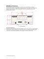
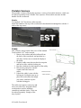
Portable Scoreboards
User Guide
F983 Rev. 201406
Customer Service Department
www.coloradotime.com
Email: [email protected]
Phone: +1 970-667-1000
Toll Free U.S. /Canada 800-287-0653
Fax: +1 970-667-1032
Manufacturer:
Everlast Climbing Industries, Inc.
DBA Colorado Time Systems
1551 East 11th Street
Loveland, CO 80537 USA
Sales : 1-800-279-0111 or +1 970-667-1000
Service: 1-800-287-0653 or +1 970-667-1000
Service Fax: 970-667-1032
Web: www.coloradotime.com
Email: [email protected]
Product Identification
Product: Multisport Portable Scoreboards
Model Numbers: MS-0028 through MS-0036
Power Specification
320W power supply: 100-240V, 50/60Hz, max 4A
Information in this manual is subject to change without notice. Pictures and illustrations
may not accurately depict your version. Please check our website for the most current
information; our user manuals are available online in the customer service section of our
website.
Part Number F983, Rev. 201406
©2014 Colorado Time Systems. All rights reserved.
Contents
Portable Scoreboards ........................................................................................... 1
Product Overview ........................................................................................................... 1
Installation....................................................................................................................... 1
Setting Module, Channel and PAN ............................................................................. 1
Installation Overview .................................................................................................. 2
Wall Mount Versions .................................................................................................. 3
Portable Versions ........................................................................................................ 4
Operating Instructions ..................................................................................................... 6
Batteries ...................................................................................................................... 6
Tabletop controller ...................................................................................................... 6
Handheld controller .................................................................................................... 6
Sports Timer................................................................................................................ 7
Replacing batteries ...................................................................................................... 7
Standards followed.......................................................................................................... 9
Product Overview
Portable scoreboards display time, 2-digit score and period for a variety of team sports.
Optional dots can display sport-specific information such as possession and bonus
indicators or time outs remaining.
Some versions are designed to be mounted on a wall and run from AC power only, and
do not have batteries. Other versions are designed to be portable scoreboards, and have
batteries, battery charging circuits and low battery/charging indicators. The portable
versions of the display mount to a variety of moveable structures, which can be ordered
separately from Colorado Time Systems.
The unit is controlled by a certified radio with an internal patch antenna which is
protected from damage. They can also be controlled with wired data from CTS sports
consoles. The displays feature an indoor/outdoor metal enclosure and plastic weather
covers over the digits.
The internal, protected horn creates multiple customizable sounds with different tones
and volumes selectable through the tabletop controller. This allows the same physical
horn to serve multiple functions (e.g., both game horn and shot clock horn) and have
different sounds for each function.
Installation
Setting Module, Channel and PAN
In order to receive data from a controller, a scoreboard must be set to the same Channel
and PAN as the controller. Additionally, the scoreboard’s Module number must be
selected as active in the appropriate menu of the controller (see controller manual for
more information.) If two or more scoreboards are set to have the same Channel, PAN,
and Module, those scoreboards will show the same data. If two controllers are set to the
same Channel, PAN, and Module, erroneous data will be displayed on the scoreboard(s).
If you have more than one scoreboard and are using the tabletop controller, map out your
scoreboard strategy, and set the channel, PAN and module for each board accordingly.
For expanded examples of how to do this, refer to our website www.coloradotime.com.
The default factory settings are Channel 4, PAN 0 and Module Address 1.
To set the module, channel and PAN:
1. Make certain the unit is disconnected from AC power and turned off.
2. Remove the weather cover over the time digits (top center of the board) by
turning the slotted studs a quarter turn using a flathead screwdriver so that they
are vertical. Remove the weather cover and set it in a safe place
3. Remove the digit to the left of the colon. Using a Phillips head screwdriver,
unscrew the retaining screws and set them in a safe place. Carefully lean the digit
against the enclosure.
1 Portable Scoreboards
4. Set the module, channel and PAN using the dip switches on the circuit board
immediately behind the digit you removed:
DIP switch settings (Off = 0, On = 1)
Module: Switches 1-5 of S1. 01 to 1E are valid.
0 0 0 1 0 08
1 0 0 0 0 01
1 0 0 1 0 09
0 1 0 0 0 02
0 1 0 1 0 0A
1 1 0 0 0 03
1 1 0 1 0 0B
0 0 1 0 0 04
0 0 1 1 0 0C
1 0 1 0 0 05
1 0 1 1 0 0D
0 1 1 0 0 06
0 1 1 1 0 0E
1 1 1 0 0 07
1 1 1 1 0 0F
00001
10001
01001
11001
00101
10101
01101
11101
10
11
12
13
14
15
16
17
00011
10011
01011
11011
00111
10111
01111
11111
18
19
1A
1B
1C
1D
1E
1F (this is test mode)
NOTE: switches 6-8 of S1, next to the Module switches, should not be changed.
Doing so will cause the display to cease functioning properly.
Channels: Switches 1-4 of S2. 0 to 11 are valid
PAN ID: Switches 5-8 of S2. 0 to 15 are valid
0000 0
0010 4
1000 1
1010 5
0100 2
0110 6
1100 3
1110 7
0001
1001
0101
1101
8
9
10
11
0011
1011
0111
1111
12
13
14
15
5. Reattach the digit and replace the weather cover. Turn the slotted studs to
horizontal. They will snap into place with moderate pressure.
Installation Overview
Some models are designed to be mounted on a wall or fixed mounting structure and to
run from AC power only (no batteries). The model number is on the serial number label
on the side of your scoreboard. The wall mount model numbers are MS-0028, MS-0029
and MS-0030. If you are installing one of these models, please skip ahead to the Wall
Mount Versions section, on page 3.
Most models (MS-0031 through MS-0036) are designed to be portable scoreboards. If
you have one of these versions, skip ahead to the Portable Versions section, on page 4.
2 Portable Scoreboards
Wall Mount Versions
Determine the location for the display. It is the owner’s responsibility to choose a
location where the wall composition or mounting structure can support the weight of the
display without batteries, which is 40 pounds (18.1 Kg). Installation must meet all
national and local codes.
Electrical Installation
Connect the wall-mounted scoreboard to standard outlet (120V or 230V) 9 feet from right
end of display with the supplied power cord. The display is grounded through the power
connection. For an outdoor installation, the receptacle must be outdoor rated.
3 Portable Scoreboards
Portable Versions
The portable versions of the display mount to a variety of moveable structures, which can
be ordered separately from Colorado Time Systems. All moveable structures include
handles for the scoreboard.
Handles
Tool needed: 3/16” hex driver (Allen wrench)
Install the handles to the top of the scoreboard in the threaded mounting holes with the 1inch socket cap screws.
Caddy
This version is shown on the front cover of this manual.
Tools needed: 9/16th socket wrench
1. Remove the washers and bolts indicated from
the back of the scoreboard, and put them in a
safe place for later use to mount the display to
the caddy.
2. Push the caddy arms down to their lowest point
and lock in place with the locking pin.
3. Rest the scoreboard on the bumpers of the caddy.
4. Bolt securely into place with the
washers and bolts removed
earlier.
5. Unlock the caddy’s arms with the
locking pin. Swing the arms up to
place the scoreboard at the height
you want it, and lock in place
with the locking pin.
The caddy can support a center tray and
one or two side trays, designed to hold
scoreboard accessories including
controller(s) and shot clocks. Trays can
be ordered separately. Simply set the
trays in place.
4 Portable Scoreboards
Stands
Tools needed: adjustable wrench or 7/16” nut driver
The stand kit includes handles, stands, stand brackets and the necessary hardware.
1. Attach the brackets to the sides of the scoreboard with the ½-inch screws and the
split washers. The washer goes between the screw and the bracket. Tighten with
the adjustable wrench or nut driver.
2. Lay the scoreboard(s) on a table and slide the pipe stands in so that on each side,
one foot is facing the front of the board and one is facing the back, as shown.
Insert the speed pins to hold the stands in place.
3. Turn the scoreboard(s) right side up to rest on the stand.
DO NOT use stands in situations with high winds.
Short Legs
Tools needed: adjustable wrench or 7/16” nut driver
The short legs kit includes handles, legs, and hardware to attach them all. Attach the legs
with the hardware included to the threaded mounting holes in the bottom of the
scoreboard.
5 Portable Scoreboards
Operating Instructions
Batteries
When used indoors and away from water, the portable versions of the scoreboard can be
run either on battery or AC power.
When used outdoors or near a pool deck or other water, the portable scoreboard must be
run from battery power only. Fully charged batteries will run the scoreboard for about 10
hours.
If one or both of the battery indicators on the right end of the scoreboard glows red, the
batteries are getting low and need to be recharged as soon as possible to prevent
shortening the life of the batteries. The low battery indicator lights when the batteries are
down to 11V. If the batteries are discharged to 10V, the scoreboard will automatically
shut down to prevent immediate damage. Running on low voltages greatly stresses lead
acid batteries and shortens their functional life.
You can extend the life of the batteries by recharging them for a minimum of 8 hours
immediately after each use and by making sure that the scoreboard is switched off when
not in use. To recharge your batteries, simply plug the scoreboard in to AC power. The
scoreboard should only be charged indoors and away from water. The battery indicators
will glow green while the batteries are charging. When the batteries are fully charged, the
scoreboard goes to trickle charge to keep them full.
The scoreboard can display data it receives from a tabletop controller, a handheld
controller, or from a sports console such as the System 6.
Tabletop controller
Follow the instructions on the tabletop controller quick reference sheet to set the tabletop
controller to the same channel, PAN and module as the scoreboard(s) you want to control
with it.
You can also set the scoreboard’s intensity with the tabletop controller.
Follow the instructions on the quick reference sheet for the specific sport you are
displaying.
Handheld controller
Follow the instructions in the handheld controller manual to set the handheld controller to
the same channel, PAN and module as the scoreboard you want to control with it. Then
follow the instructions for baseball, or follow the general instructions for other sports.
6 Portable Scoreboards
Sports Timer
The portable scoreboard can display Water Polo data from a CTS System 6 or System 5
sports timer. You can also set the scoreboard’s intensity with the System 6.
For information to display correctly on the portable scoreboard, four of the sports timer’s
scoreboard channels must be set to the factory default scoreboard channels. Specifically,
Channel 1 displayed on Module 1
Channel 2 displayed on Module 3
Channel 5 displayed on Module 0D
Channel 12 displayed on Module 5 (only applies to System 6; not available on System 5)
You can easily set all scoreboard channels to the factory defaults through the Scoreboard
menu, Define Module submenu, by choosing Default Scbds. Refer to your System 6 or
System 5 Water Polo manual for more information.
In addition, on a System 6, also go to the Game Setups menu, Scoreboard Time Display
submenu, and choose “Don’t Show Running Tenths” instead of “Show Running Tenths.”
Connect your Sports Console to the scoreboard in one of two ways:
1. Directly with data cables (R-xxDC)
2. Connect the Sports Console to a 2.4 GHz wireless adapter (WA-2) and follow the
instructions in the WA-2 user manual to set it to the same channel and PAN as the
scoreboard(s) you want to control. Be sure to set the dip switch for Sports
Console to Multisport Scoreboard.
Replacing batteries
Eventually, your batteries will fail to hold a charge and will need to be replaced. Batteries
can only be replaced with Powersonic PS1270 UL recognized (MH20845) gel cell
batteries. The portable scoreboards take 4 batteries, which should all be replaced at the
same time. These are available from Colorado Time Systems (part number R-420-003).
Tools required: Phillips head screwdriver, 11/32 socket driver
1. Make sure the scoreboard is disconnected from AC power and that the power
switch is turned off.
2. If your scoreboard is mounted on a caddy, remove it from the caddy.
3. Place scoreboard face down on a protected work surface; two people
recommended.
4. Remove the screws and washers from around one
of the battery/backplate assemblies, and put them
in a safe place for later installation.
5. Use a screwdriver or similar tool to gently pry up
the battery/backplate assembly.
7 Portable Scoreboards
6. Gently place assembly on back of enclosure as
shown, with battery terminals towards the opening.
Disconnect battery cables from battery. Take care
not to short the battery terminals, for example by
touching them to the enclosure or by touching both
of them with a screwdriver.
7. Using the socket wrench, loosen and remove the
nuts, and put them in a safe place for later
installation.
8. Lift the battery bracket off of the batteries.
9. Properly dispose of the spent batteries.
10. Place the new batteries on the backplate in the same way the old batteries were:
with the terminals to the outside.
11. Place the battery bracket over the batteries, and securely fasten with the nuts.
12. Gently place assembly on back of enclosure as shown, with battery terminals
towards the opening. Connect battery cables from inside scoreboard to battery,
taking care to connect one pair of wires to one side of the battery, black wire to
black terminal and red wire to red terminal. Connect the other pair of wires to the
other side of the battery pack in the same way. Turn on the scoreboard with the
power switch and verify that the digits light. Turn off the scoreboard.
13. Gently flip battery/backplate assembly over and align the holes in the backplate
with the holes in the enclosure. Install the battery/backplate assembly into the
back of the scoreboard using the screws and washers removed earlier.
14. Repeat steps 4 - 13 for the second battery/backplate assembly.
8 Portable Scoreboards
Standards followed
UL 48
Issue:2011/09/02 Ed:15 Rev:2012/05/04 UL Standard for Safety Electric Signs
CAN/CSA C22.2#207
Issue:1989/01/01 Portable and Stationary Electric Signs and Displays General
Instruction No 1: 1989/10/01 - (R2008)
FCC 47CFR 15B clB
Issued:2011/04/21 Title 47 CFR Part 15 Subpart B Unintentional Radiators Class A Verification
ICES 003
Issue:2004/01/01 Issue No.4 Interference-Causing Equipment Standard, Digital Apparatus
9 Portable Scoreboards
Customer Service Department
www.coloradotime.com
Email: [email protected]
Phone: 970-667-1000
Toll Free U.S. and Canada 800-287-0653
Fax: 970-667-1032