1
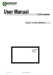
LCD Monitor Models: VT550 Series VT550 Series 1 www.vartechsystems.com Revision History Version 1.0 1.1 Date Jun. 31, ‘10 Sep. 30, ‘10 VT550 Series Page Section Description All VT550 SERIES Specification was first issued. 29 Updated “Select Source” input signal order in Display Setting Menu 34 Updated default setting 37 Updated SDTV timing on component signal 2 www.vartechsystems.com Contents IMPORTANT SAFETY INSTRUCTIONS................................................................................................................................4 SAFETY PRECAUTIONS..........................................................................................................................................................4 INSTALLATION (WHEN INSTALLING THE MONITOR, PLEASE FOLLOW THE INSTRUCTIONS IN THE MANUAL) .....................................5 USE .....................................................................................................................................................................................6 CLEANING ............................................................................................................................................................................6 WARNING FOR USE..............................................................................................................................................................7 USE .....................................................................................................................................................................................7 EXEMPTIONS ........................................................................................................................................................................7 FEATURES .............................................................................................................................................................................8 PACKAGE CONTENTS .........................................................................................................................................................8 POWER INPUT .....................................................................................................................................................................12 POWER INTERFACE .............................................................................................................................................................12 SIGNAL SOURCE INPUT .......................................................................................................................................................13 OPERATING THE MONITOR...............................................................................................................................................13 THE SIDE CONTROLLER OF THE MONITOR .............................................................................................................................14 THE REMOTE CONTROL (RCU) INSTRUCTIONS ....................................................................................................................16 CHANGE THE RCU BATTERY ..............................................................................................................................................16 CHANGE THE RCU BATTERY ..............................................................................................................................................17 DISPLAY MODE ...................................................................................................................................................................18 OSD (ON SCREEN DISPLAY) MENU FUNCTION.....................................................................................................................21 ON-SCREEN DISPLAY (OSD)...............................................................................................................................................25 DEFAULT SETTING .............................................................................................................................................................34 TOUCH OPERATION ...........................................................................................................................................................35 SUPPORTED TIMING ..........................................................................................................................................................37 SPECIFICATION...................................................................................................................................................................38 TROUBLESHOOTING .........................................................................................................................................................39 COMPLIANCE ......................................................................................................................................................................39 APPENDIX I: MOVING AND CARRYING NOTICE .............................................................................................................40 APPENDIX II: STANDS AND WALL MOUNT INSTALLATION .........................................................................................41 APPENDIX III: WALL MOUNT SAFETY NOTES ................................................................................................................43 VT550 Series 3 www.vartechsystems.com ※ Please read this user’s manual thoroughly and completely before operating this monitor. Important Safety Instructions Before using the monitor, please read this user’s manual thoroughly to help protect against damage to your own and other people’s property and ensure your own and other people personal safety. Be sure to observe the following instructions. For your safety, be sure to observe the warnings located in this manual. For installation or adjustment, please follow this manuals instruction and refer all servicing to qualified service personnel. Safety Precautions If smoke or peculiar smell comes from the monitor, remove the power plug from the outlet immediately. Failure to do so may result in fire or electrical shock. Contact your dealer for inspection. If the monitor has been turned on but there isn’t a picture, remove the power plug from the outlet immediately. Failure to do so may result in fire or electrical shock. Contact your dealer for inspection. If water is spilled or objects are dropped inside the monitor, remove the power plug from the outlet immediately. Failure to do so may result in fire or electrical shock. Contact your dealer for inspection. If the monitor is dropped or the cabinet is damaged, remove the power plug from the outlet immediately. Failure to do so may result in fire or electrical shock. Contact your dealer for inspection. To turn off the power of the monitor, press ”O” on the main power switch at side of monitor. The power standby/on indicator will go off and the monitor cannot to be turned on/off by using the POWER button on the remote control. (To turn on/off the monitor by the remote control, press the main power switch again and light the power standby/on indicator.) When turning off the monitor by pressing the POWER button on the remote control, the main power of the monitor is not turned off completely. To disconnect the monitor completely from power supply, remove the power plug from the outlet. Press “O” to turn off the monitor completely VT550 Series 4 www.vartechsystems.com If the power cord or plug is damaged or becomes hot, turn off the main power switch of the monitor, make sure the power plug has cooled down and remove the power plug from the outlet. If the monitor is still used in this condition, it may cause a fire or an electrical shock. Contact your dealer for replacement. Installation (when installing the monitor, please follow the instructions in the manual) Don't install in a high-temperature environment. If the monitor is used in high-temperature or in direct sunlight, it may cause the case or other parts become distorted or damaged resulting in overheating or electric shock. Don't install in a high-humidity environment. This may cause overheating or electric shock. Don't install near any heat sources such as radiators, heat registers, stoves, or other apparatus that produce heat. This may cause a fire or electric shock. Don't overload outlets or cables beyond electrical capacity. Don't use extension cords as it may cause a fire or electric shock. Don't insert the power plug into an outlet other than 100~240V AC. This may cause a fire or electric shock. Don’t use a damaged power plug or worn outlet. Don’t insert the improper power plug it may cause a fire and electric shock. Don't place the monitor on an unstable shelf or surface. The monitor may fall causing injury. Please install on a horizontal, stable, level surface. Don't place objects on the monitor. If the monitor is covered or the vents are blocked, the monitor could overheat and cause a fire. If metal or liquid gets into the monitor, it may cause a fire or an electrical shock. Do not put heavy objects on the monitor as it may fall causing injury. Please keep a10cm minimum distance between the monitor and the wall for sufficient ventilation. Don't move the monitor when it is connected to the power cord and AV cables. When moving the monitor, make sure to remove the power plug and cables from the outlet or source. When unpacking or carrying the monitor, at least 2 people are needed. Make sure the monitor is carried upright. Transport the monitor upright. Avoid placing the monitor face up or down. Handle the monitor gently. Do not drop. VT550 Series 5 www.vartechsystems.com Use If you encounter a problem during installation, please contact your dealer for assistance. Don’t repair or open the monitor by yourself. Failure to do so may result in fire or electrical shock. Contact your dealer for inspection. Protect and correctly use the power cord/plug. Don't press heavily on the power cord/plug. Don't step on the power cord/plug. Before inserting the power plug into the wall outlet, connect the power cord to the monitor. Don't operate the monitor with a damaged power cord or it may damage the monitor. Using the extension cords (not recommended) If an extension cord must be used, ensure the voltage rating exceeds the max power consumption of the monitor, if the voltage rating is less than the monitor, it will cause the extension cord to overheat. If there is thunder or lightning, don’t touch the monitor or the power plug. This may cause an electric shock. Don’t use any kind of liquid on the monitor. If liquid is spilled on the monitor, remove the power and ask an qualified service personnel to check the monitor. If the liquid get’s on the monitor’s screen, please clean it with a dry and soft cloth immediately. Don’t use any harsh chemical on the monitor. If metal or liquid gets into the monitor, it may cause a fire or an electrical shock. Don’t install or remove the power plug with wet hands. This may cause an electric shock. If the monitor will not be used for a long period of time, unplug the monitor. This may cause premature wear of electrical components or fire. Don’t press on the LCD panel. This may cause personnel injury or panel damage. Don't push or shake the monitor. This may cause damage or injury. If the glass of the monitor panel is broken, liquid may escape. Please don't touch the liquid. If liquid get into your eyes or touches your skin, wash with the clean water and seek medical attention immediately. Precautions with the remote control batteries. Please only use approved AAA type batteries. Please be sure to insert batteries by matching the + and -. Don’t recharge, heat, disassemble, short or throw batteries into a fire. Don’t mix a new battery with a used one. Don’t mix different types of batteries together (only use the specified type). Or, it may cause burn and injury. Cleaning If dust has collected on the power plug, removed the plug from the outlet and clean off the dust. Dust build-up may cause a fire. Take off the power plug before cleaning. Failure to do so may result in electrical shock or damage. Cleaning the surface of the monitor. VT550 Series 6 www.vartechsystems.com When the surface of the monitor becomes dirty, please wipe the surface lightly with a soft clean cloth. If the surface requires additional cleaning, lightly moisten the cloth with rubbing alcohol. Do not to let alcohol enter the monitor as it may cause electrical shock or damage. Warning For Use Use Do not use this “VT550 Series model” on the ground. If ground usage is necessary, there are 4 screw holes on the stand, please use the M8x15 screws to fix the monitor to the ground. The monitor may overheat during operation. Please be careful. Transport the monitor upright with proper packaging. Avoid placing the monitor face up or down. Be careful not to bump to the monitor. Do not send a static (non moving) image this monitor, or it may cause image ‘burn-in’ or image retention. “Burn in” and/or image retention is not covered under warranty. Make sure to change the image on the monitor periodically. It is recommended to turn off the monitor for at least 6 hours after 18 hours of usage in a day to avoid image retention. Warning: This is a class A product. In a domestic environment, this product may cause radio interference in which case the user may be required to make adequate measures. Exemptions This product isn’t warranted for any damage caused by natural disaster (such as earthquake, thunder, etc), fire, acts by third parties, accidents, owner’s intentional misuse and fault, or uses in other improper conditions. This product isn’t warranted for incidental damages (such as profit loss or interruption in business, modification or erasure of record data, etc.) caused by use or inability to use of this product. This product isn’t warranted for any damage caused by inappropriate operation, or from not following the user manual. This product isn’t warranted for any damage caused by misuse or malfunction through simultaneous use of this product and the connected equipment or software. This product isn’t warranted for any damage caused by neglect of the instructions described about installation. This product isn’t warranted for any damage caused by improper installation. This product isn’t warranted for any damage caused by disassembly, modification or repair by non-authorized service center or people. VT550 Series 7 www.vartechsystems.com Features High-resolution Full-HD 120Hz panel This monitor supports a 1920 x 1080 HDTV format and can display true 1.073G colors. Full array of PID connectivity Video system Input: HDMI x2 COMPONENT (RCA) x1 (option) VIDEO (RCA) x1 (option) S-VIDEO (Mini Din 4 pin) x1 (option) RGB Input: Communication PC (VGA D-Sub 15pin) x1 RS-232C in D-sub 9pin PC (DVI D-sub 24 pin) x1 (option) RS-485 in/out option: only available on Advanced version Other functions High color saturation. 2 HDMI v1.3 inputs with HDCP. SPDIF output. Signal source auto detection. OSD keypad lock function. PIP/ PBP function. Please see the chapter “Display mode ” Overscan function. Supports input main / sub source detection. Package Contents Unpacking The VT550 is packed in a carton box and may be banded to 2 types of custom pallet depends on the number of units shipped. The VT550 is packed using cushions to protect the monitor during shipping. Before unpacking your monitor, prepare a stable, level, and clean surface near a wall outlet. Set the LCD Monitor box in an upright position and open from the top of the box before removing the top cushions. Step 1: Remove the white handle and cut the banding VT550 Series 8 www.vartechsystems.com Step 2: Remove the top cushion and take the accessories Bag out. Packing list Item Q’ty 1 VT550 1 set 2 Carton 1 pcs 3 Bottom cushion 1 pcs 4 Top cushion 1 pcs 5 Packing bag 1 pcs Accessories Bag 6 Remote control Batteries Power cord D-SUB 15pin cable 7 Carton lock VT550 Series 9 www.vartechsystems.com 1 pcs 2 pcs 1 pcs 1 pcs 6 pcs Contents of the Accessory Bag VGA Cable (D-sub) Power Cord –black OSD Remote Control 2 piece batteries (AAA) inside. USB Cable VT550 Series 10 www.vartechsystems.com Dimensions VT550 Series 11 www.vartechsystems.com Installation Environmental state Operating temperature: 5˚C ~ 35˚C (Fahrenheit : 41˚F ~ 95˚F) Humidity : 85% RH (Max) Power Input Power Cord The included power cord is used to connect the side controls of the LCD monitor and the wall outlet. Connect the power cord into main power of the monitor, “-” is power on, “O” is power off. Input: 100-240V~ 5A 50/60Hz The side of control Single Input Interface “I“ is power on “O” is power off Main power – Switch AC In socket AC Out socket Power Interface Main power - switch & AC socket. Please see the chapter “Power input ” The side controller of the monitor The remote control (RCU) VT550 Series 12 www.vartechsystems.com Input Interface Signal Source Input 1 2 3 4 5 6 7 8 9 10 11 12 13 14 15 16 17 Name RS232C input x 1 RS485 input x1 RS485 output x1 HD-SDI 1 input x1 HD-SDI 2 input x1 HD-SDI output x1 HDMI 1 input x1 HDMI 2 input x1 DVI-D input x1 VGA (PC) input x 1 PC audio in x1 IR Extender x1 SPDIP output x 1 Y-Pb-Pr (Y-Cb-Cr) input x 1 Audio for Component input x 1 S-video input x 1 Video input x 1 Audio for S-Video/Video input x 1 Power cord output Power cord input AC switch RS232 for Touch USB for Touch 4-Point calibration for Touch Operating The Monitor VT550 Series Connecter D-Sub 9 pin RJ-45 RJ-45 BNC BNC BNC D-Sub 24 pin D-Sub 15 pin Mini jack Mini jack RCA G/B/R RCA L/R Mini Din 4 pin RCA RCA L/R AC output AC input ON/OFF D-Sub 9 pin Type B Female 13 Remarks Standard Standard Standard Optional for Advanced ver. Standard Standard Advanced ver. Standard Advanced ver. Advanced ver. Standard Advanced ver. Advanced ver. Advanced ver. Advanced ver. Advanced ver. Standard Standard Standard Optional for 55AVT 55AVT only 55AVT only www.vartechsystems.com The side controller of the monitor Input connecter Main Power switch AC In. OSD Key Pad function List Key Power Power on/Power off Source Source selection (toggle) Menu Right/Volume + Menu Left/Volume - Menu Up Menu Down Menu/Exit VT550 Series Descriptions Menu/Exit selection 14 www.vartechsystems.com LED ON: -Power ON-Stand by Indicator -Remote Control Receiver Power Status Green Orange Off Condition Power on Power off Power saving mode Select LED on via menu (Front LED: On) AC off Power on Select LED on via menu (Front LED: Off) LED OFF: The LED turns completely off when in the “off” mode regardless of the monitor being on or off. VT550 Series 15 www.vartechsystems.com The Remote Control (RCU) Instructions No Function Description Turns the monitor on and off Provides source and resolution information INFO Selects the PC RGB source VGA Selects the PC DVI source (Advanced ver.) DVI Selects the HDMI source 1 HDMI 1 Selects the Component source (Advanced ver.) COMP 1 Selects the Composite Video source (Advanced AV 1 (VIDEO 1) ver.) Selects the HDMI source 2 HDMI 2 Not available at this model COMP 2 AV 2 (VIDEO 2) Not available at this model Selects the HD-SDI source 1 (Advanced ver.) HD-SDI 1 Turns the PIP feature on and off PIP Selects the S-Video source (Advanced ver.) S-V Selects the HD-SDI source 2 (Advanced ver.) HD-SDI 2 Swaps the main source & sub source picture SWAP Selects the secondary sub-source P-SOURCE Opens the monitor’s on-screen menu system. When the menu system is already open, pressing this MENU button will select the previous submenu Navigates through submenus and settings ,, , Closes the menu system EXIT Selects highlighted menu choices ENTER Toggles between different aspect ratios (Auto, SCALING Native, 4x3, 16x9, 16x10 and Letterbox) Freezes the current source image FREEZE Turns off the sound (Advanced ver.) MUTE Adjusts the brightness BRIGHT Adjusts the contrast CONTRAST Synchronizes the monitor to the source AUTO Allows selection of the different sources SOURCE Decreases the sound volume (Advanced ver.) VOLUMEIncreases the sound volume (Advanced ver.) VOLUME+ Hot Key : OSD Menu Lock/Unlock Control Lock: Press Enter, Enter, Exit, Exit, Enter and Exit on the controller by sequence and OSD will be locked. Unlock: Press Enter, Enter, Exit, Exit, Enter and Exit on the controller by sequence again and OSD will be unlocked. VT550 Series 16 www.vartechsystems.com Change The RCU Battery 1. Remove the battery cover Slide back and remove the battery cover in the direction of the arrow. Insert the batteries 2. Align and insert two AAA batteries according to their plus and minus ports (as indicated in the remote control). 3. Replace the battery cover in the direction of the arrow and snap it back into place. Close the battery cover i. ii. iii. Used batteries needed to follow the city rule to be discarded. Avoid keeping used, old batteries inside the remote control, causing leakage of internal liquid resulting metal rust or fatal damage to the remote control hand unit. Battery to be used according to the instruction CAUTION About the remote control Don’t drop, shake or bump. Don’t place on wet materials. Don't dismantle. Don’t place in locations with exposure to high-temperature or high-humidity levels. VT550 Series 17 www.vartechsystems.com Display Mode Turning the monitor on 1. 2. 3. Correctly insert the power cord into monitor and into the power outlet. Ensure the AC switch is set to “—“. Press the power button on the remote or side control panel. Turning the monitor off With the power on, press the power button on the remote or side control panel to put the monitor in a standby mode. To turn off power completely, turn the AC switch to “O” or disconnect the AC power cord from the power outlet. Note: If there is no signal input for a period of time, the monitor will automatically go to standby mode. Adjusting the Volume 1. Using the remote, press the VOLUME- or VOLUME+ to increase or decrease the volume. 2. Press the MUTE button to temporarily turn off all sound. To restore the sound, press the MUTE button again. Selecting the input source 1. 2. 3. Using the remote, press the desired source button (VGA, HDMI1, HDMI2, COMP, VIDEO or S-V) Or press SOURCE on the monitor keypad, use the arrow buttons ( ) to navigate to the desired input source, and press ENTER: HDMI 1 HDMI 2 VGA Component (Advanced ver.) S-Video (Advanced ver.) Composite Video (Advanced ver.) DVI (Advanced ver.) HD-SDI (Advanced ver. option) When the monitor cannot find a source, a “No signal” message will appear. VT550 Series 18 www.vartechsystems.com PIP mode 1. 2. Select the main source – Using the remote, press the desired source button (VGA, HDMI1, HDMI2, COMP, VIDEO or S-V). Turn on PIP: Using the remote, press PIP. PIP Main Large PIP Middle PIP Small PIP 3. 4. To select the PIP/ sub-source: Using the remote, press P-SOURCE and use the arrow buttons ( ) to navigate to the desired sub-source. Press ENTER. To change the size and position of the sub-source: Using the remote, press P-POSITION to toggle through the options. TopLeft Top-Right Small PIP Main Bottom-Left 5. BottomRight To switch the main source and the subsource: Using the remote, press SWAP. SWAP Mai VT550 Series 19 www.vartechsystems.com 6. 7. To switch audio between the main source and the subsource: Using the remote, press AUDIO. Note: For additional PIP functionality, press MENU and navigate to the Display Settings menu. Use the arrow buttons ( ) to navigate to the desired PIP feature and press ENTER. Press to toggle through the associated options and press ENTER to select the highlighted option. Main Source Sub Source 8. Side by Side (Picture-by-Picture): Press P-POSITION button choose “Side by side” mode, then the main source and the subsource will be on the screen display. Main PIP PIP Screen Table HDMI 1 HDMI 2 VGA DVI Component S-Video Video VT550 Series HDMI 1 - - Yes - Yes Yes Yes HDMI 2 - - Yes - Yes Yes Yes VGA Yes Yes - Yes Yes Yes Yes DVI - - Yes - Yes Yes Yes 20 Component S-Video Yes Yes Yes Yes Yes Yes Yes Yes Yes - Yes - Yes Yes www.vartechsystems.com Video Yes Yes Yes Yes Yes Yes - OSD (On Screen Display) Menu Function Graphics Mode Main Menu Sub-Menu Scheme Brightness Contrast Sharpness Saturation Hue Backlight Image Settings Gamma & Color Temp Gamma Description Disabled in Graphics mode Adjust the brightness of the screen Adjust the contrast of the screen Adjust the sharpness of the screen Disabled in Graphics mode Disabled in Graphics mode Adjust the backlight Select the Gamma Color Temp Select the Color Temp Red Gain Green Gain Blue Gain Red Offset Green Offset Blue Offset Zoom Auto Scan Select the Red Gain Select the Green Gain Select the Blue Gain Select the Red Offset Select the Green Offset Select the Blue Offset Adjust the aspect ratio of the screen Adjust the zoom function Select the Auto scan function Select source Select the main input source PIP mode Select PIP mode PIP Position Select PIP location Aspect Ratio Adjust the aspect ratio of the screen Sub-Sub menu Aspect Ratio Main Display Settings PIP Side by Side Scale Auto Scan Select source Audio Settings Volume Bass Treble Balance HDMI Audio Input OSD Transparent OSD Location Basic Settings OSD Zoom OSD Rotation OSD Language OSD Timeout Sleep Timer Real Time Clock VT550 Series Select the Auto scan function Select the main input source When PIP mode is enable Adjust volume Adjust Bass volume Adjust Treble volume Adjust the balance of the screen SPDIF & audio input Control Adjust the OSD transparent function Adjust the OSD location Adjust the OSD size (Disable in portrait type) Adjust the OSD rotation Select the OSD language Select the OSD timeout seconds Select the sleep timer Setup Date & Time 21 Setting 0~100 0~100 0~24 0~100 2.2, Off 5000K ,6500K,7500K, 9300K,User 128 ~ 384 128 ~ 384 128 ~ 384 -50 ~ 50 -50 ~ 50 -50 ~ 50 Full Screen, Native, Letter Box, Pillar Box ►◄ Off, On VGA,HDMI1/2,DVI,Video,S-V, Component,SDI 1/2 Off, Large PIP, Medium PIP, Small PIP, Side by Side Bottom-Right, Top-Left Top-Right, Bottom-Left Full Screen, Native, Letter Box, Pillar Box ► PIP ◄ Main ▲ Zoom IN ▼ Zoom Out Off, On VGA,HDMI1/2,DVI,Video,S-V, Component,SDI 1/2 0 ~ 100 0 ~ 20 0 ~ 20 0 ~ 20 HDMI/PC 0 ~ 100 ►◄▲▼ Off, On 0°/90°/180°/270° English/ Chinese 5~120 sec. Off, 15,30,60,90,120 Min. www.vartechsystems.com Main Menu Sub-Menu Sub-Sub menu Auto Adjustment Image Position Advanced Settings Phase Clock Flesh Tone Front LED IRFM Band rate Monitor ID Light Sensor Factory Reset VGA ADC Settings System Status Channel Information VT550 Series ADC Mode User ADC Calibration Restore ADC to Default Source Resolution Firmware Version Description Select Auto adjustment function ► 0~ -100 ◄ 0 ~ 100 ▲ according to resolution ▼ according to resolution According to resolution According to resolution Disabled in Graphics mode Select the front LED function Select the anti burn in mode function Setting the band rate of monitor Setting the ID of monitor Select light sensor function Reset to the factory default setting Select ADC setting Setting Off, On Off, On Off, On 115200,38400,19200,9600 1 ~ 255 Off, On Yes, No Default, User Execute User ADC Calibration Restore User ADC setting to factory ADC default Show the name of input source Show the current resolution Show the firmware of the monitor 22 www.vartechsystems.com Video Mode Main Menu Image Settings Sub-Menu Description Sub-Sub menu Scheme Select the scheme Brightness Contrast Sharpness Saturation Hue Backlight Gamma Adjust the brightness of the screen Adjust the contrast of the screen Adjust the sharpness of the screen Adjust the saturation of the screen Adjust the hue of the screen Adjust the backlight Select the Gamma Color Temp Select the Color Temp Red Gain Green Gain Blue Gain Red Offset Green Offset Blue Offset Select the Red Gain Select the Green Gain Select the Blue Gain Select the Red Offset Select the Green Offset Select the Blue Offset Aspect Ratio Adjust the aspect ratio of the screen Zoom Auto Scan Adjust the zoom function Select the Auto scan function Select source Select the main input source PIP mode Select PIP mode PIP Position Select PIP location Aspect Ratio Adjust the aspect ratio of the screen Color Temp & Gamma Main Display Settings PIP Side by Side Scale Auto Scan Select source Audio Settings Volume Bass Treble Balance HDMI Audio Input OSD Transparent OSD Location OSD Zoom Basic Settings OSD Rotation OSD Language OSD Timeout Sleep Timer Real Time Clock VT550 Series Select the Auto scan function Select the main input source When PIP mode is enable Adjust volume Adjust Bass volume Adjust Treble volume Adjust the balance of the screen SPDIF & audio input Control Adjust the OSD transparent function Adjust the OSD location Adjust the OSD size (Disable in portrait type) Adjust the OSD rotation Select the OSD language Select the OSD timeout seconds Select the sleep timer Setup Date & Time 23 Setting User,Vivid,Cinema,Game Sport 0~100 0~100 0~24 0~100 0~100 0~100 2.2, Off 5000K,6500K,7500K, 9300K,User 128 ~ 384 128 ~ 384 128 ~ 384 -50 ~ 50 -50 ~ 50 -50 ~ 50 Full screen, Pillar Box, Letter Box, Native ►◄ Off, On VGA,HDMI1/2,DVI,Video,S-V, Component,SDI 1/2 Off, Large PIP, Medium PIP, Small PIP, Side by Side Bottom-Right, Top-Left Top-Right, Bottom-Left Full screen, Pillar Box Letter Box ► PIP ◄ Main ▲ Zoom IN ▼ Zoom Out Off, On VGA,HDMI1/2,DVI,Video,S-V, Component,SDI 1/2 0 ~ 100 0 ~ 20 0 ~ 20 0 ~ 20 HDMI/PC 0 ~ 100 ►◄▲▼ Off, On 0°/90°/180°/270° English/ Chinese 5~120 sec. Off, 15,30,60,90,120 Min. www.vartechsystems.com Main Menu Advanced Settings System Status Sub-Menu Sub-Sub menu Auto Adjustment Image Position Phase Clock Flesh Tone Front LED IRFM Band rate Monitor ID Light Sensor Factory Reset Source Channel Resolution Information Firmware Version VT550 Series Description Disabled if not a VGA mode Disabled if not a VGA mode Disabled if not a VGA mode Disabled if not a VGA mode Select the flesh tone setting Select the front LED function Select the anti burn in mode function Setting the band rate of monitor Setting the ID of monitor Select light sensor function Reset to the factory default setting Show the name of input source Show the current resolution Setting Off, High, Medium, Low Off, On Off, On 115200,38400,19200,9600 1 ~ 255 Off, On Yes, No Show the firmware of the monitor 24 www.vartechsystems.com On-Screen Display (OSD) Menu Overview Image settings – Main setting Display settings (PIP) Audio Settings VT550 Series 25 www.vartechsystems.com Basic Settings Advanced Settings System Status VT550 Series 26 www.vartechsystems.com Navigating through the Menu System 1. 2. 3. With the power on, press MENU. The Image Settings menu will display. Within the menu, use ,,, , and ENTER to navigate through the menus and adjust options. Press MENU to return to the previous menu. To exit the menu system, press EXIT. Image Settings Menu This menu is used for making common image adjustments. Scheme Press or to select one of the following: Options: User, Vivid, Cinema, Game, Sport Default: User Brightness Increases or decreases the brightness of picture. Press or, select the desired level, and then press ENTER. Range: 0~100; Default: 50 Contrast Increases or decreases the contrast of picture. Press or , select the desired level, and then press ENTER. Range: 0~100; Default: 50 Sharpness Adjusts the definition of picture. Press or , select the desired level, and then press ENTER. Range: 0~24; Default: 10 Saturation Adjusts the brilliance and brightness (only Video Mode). Press or, select the desired level, and then press ENTER. Range: 0~100; Default: 50 Hue Increases or decreases the green hue (Only Video Mode). Press or , select the desired level, and then press ENTER. Range: 0~100; Default: 50 Back Light Color Temp and Gamma VT550 Series Range: 0~100; Default: 80 Adjusts red, green, blue gain and red, green blue offset. 27 www.vartechsystems.com Image Settings Menu (continued) Gamma Options: Off, 2.2 Default: 2.2 Color Temp Options: User, 5000K, 6500K, 7500K and 9300K. Default: 9300K Red Gain Set Color Temperature to “User Mode” in order to adjust this setting. Range: 128~384 Default: 256 Green Gain Set Color Temperature to “User Mode” in order to adjust this setting. Range: 128~384 Default: 256 Blue Gain Set Color Temperature to “User Mode” in order to adjust this setting. Range: 128~384 Default: 256 Red Offset Set Color Temperature to “User Mode” in order to adjust this setting. Range: -50~50 Default: 0 Green Offset Set Color Temperature to “User Mode” in order to adjust this setting. Range: -50~50 Default: 0 Blue Offset Set Color Temperature to “User Mode” in order to adjust this setting. Range: -50~50 Default: 0 VT550 Series 28 www.vartechsystems.com Display Settings Menu This menu is used for common source adjustments. Main The Display Setting Mode. Aspect Ratio Changes the picture aspect ratio Press , to select the following options: Options: Full screen, Pillar Box, Letter Box ,Native Default: Full screen Zoom Range: 0~10 Default: 0 Auto Scan Range: On, Off Default: On Select Source Options: VGA, HDMI1, HDMI2, DVI, Video, S-Video, Component, SDI1, and SDI2 Default: VGA PIP PIP Mode Options: Off, Large PIP, Middle PIP, Small PIP and Side-by-Side Default: Off PIP Position Options: Bottom-Right, Top-Left, Top-Right and Bottom-Left Default: Bottom-Right Aspect Ratio Options: Full screen, Pillar Box, Letter Box Default: Full screen Side by Side Scale Submenu Options: Zoom In, Zoom Out, Main, PIP, Default and Return Auto Scan Options: On, Off Default: On Select Source Options: VGA, HDMI1, HDMI2, DVI, Video, S-Video, Component, SDI1, and SDI2 Default: HDMI VT550 Series 29 www.vartechsystems.com Audio Settings Menu This menu is used for adjusting volume settings. Volume Adjust the sound. Press or , select the desired level, and then press ENTER. Range: 0~100 Default: 50 Bass Adjust the sound in low tones (bass). Press or , select the desired level, and then press ENTER. Range: 0~20 Default: 10 Treble Adjust the sound in high tones (Treble). Press or , select the desired level, and then press ENTER. Range: 0~20 Default: 10 Balance Adjust the balance of the left and right speakers. Press or , select the desired level, and then press ENTER. Range: 0~20 Default: 10 HDMI Audio Input Select HDMI and PC audio input mode. Default: HDMI VT550 Series 30 www.vartechsystems.com Basic Settings Menu This menu is used to make initial set-up adjustments to the OSD (On-Screen Display) menu and other on-screen messages. OSD Transparent Set the menu transparency. Press or to select the desired level, and then press ENTER. Range: 0~100 Default: 0 OSD Location Adjust the menu location on the monitor (Up, Down, Left, Right). OSD Zoom Options: On, Off Default: Off OSD Rotation Select the OSD Rotation. Press select the rotation. Options: 0, 90, 180, 270 Default: 0 degree OSD Language Options: English and Chinese Default: English OSD Timeout Options: 5~120 Default: 30 Sleep Timer Set a period of time after which the monitor will switch to standby mode automatically. Press to select the desired time limit. Options: Off, 15, 30, 45, 60, 90, 120 Min Default: Off Real Time Clock Set date, and switch alarm on and off. Use ,,, to adjust these options. VT550 Series 31 www.vartechsystems.com Advanced Settings Menu Auto Adjustment Forces the monitor to reacquire and lock to the input signal. This is useful when the signal quality is marginal. Note: This feature does not continually reacquire the signal. Options: No, Yes Default: No Image Position Image location can be adjusted (Only VGA Mode). Options: Up, Down, Left, Right Phase Range: 0~63 (Only VGA Mode) Clocks Range: 0~100 (Only VGA Mode) Flesh Tone Options: Off, Low, Medium and High (Only Video Mode) Default: Off Front LED Options: On and Off Default: On IRFM Creates slight frame motion to help avoid image retention. Options: On Default: Off Baud Rate Options: 115200, 38400, 19200, 9600 Default: 115200 Monitor ID Options: 1~ 255 Default: 0 Light Sensor Options: On and Off Default: Off Factory Reset Restores all settings to their default. Options: No, Yes Default: No VGA ADC Settings Select ADC setting, User ADC Calibration, and restore factory default ADC setting. Options: Default, User Default: Default VT550 Series 32 www.vartechsystems.com System Status Menu This read-only menu provides information on the active sources and the latest firmware version. User ADC Calibration 1. When using VGA as signal source, go to Advanced Settings in OSD menu and select VGA ADC Settings, then choose User ADC Calibration. 2. A warning message (see image below) will show to make sure proper image is displayed on screen before ADC calibration begins i. Image in the green boxes, displayed on both side of the screen, has to be white and black in order to run the calibration accurately (the black and white image can be made using software like Microsoft PowerPoint) ii. The white in the left green box has to be the brightest white. iii. The black in the right green box has to be the darkest black. VT550 Series 33 www.vartechsystems.com 3. After proper image is displayed, click “Yes” to begin ADC calibration 4. During calibration process, the following image will show to notify user to wait for the calibration. 5. After calibration is completed, the display will notify user if the process is done successfully by different messages. Default Setting Item Default Value Power switch Off Brightness 50 Backlight 80 Contrast 50 Color Temp. 9300 K Source Auto Detection Off OSD Language English Auto Off Monitor ID 01 IRFM Off Baud rate VT550 Series 115200 34 www.vartechsystems.com Touch Operation 1. Connect the signal cable witch monitor, then turn on computer. 2. Connect the USB cable with monitor and computer. 3. Turn on the monitor (AC switch on). 4. Connect one side of USB cable (Type-B USB connector) on the monitor side. See below picture. (Check “Connection” section for exact location). 5. Connect the other side of USB cable (Type-A USB) to the USB port on computer. See picture below. 6. Wait for 5 seconds and the touch function is ready to go. It can be activated by pen, finger, or any other pointer. 7. This touch monitor is Microsoft Windows 7 compatible. In order to active, go to http://www.nextwindow.com/nextwindow_support/windriver.html to download the latest driver. Follow the direction in the NW Multitouch Device Driver Installation Guide (part of the compressed file along with the driver) to install the driver. 8. Once the driver is installed, restart the PC and the touch function is ready to go with MS Windows 7. 9. Operating Systems Supported: I. Microsoft Windows: i. Windows 98, NT, 2000, XP, Vista, and 7: Plug-and-play ii. Driver required to run dual-touch/gesture on Windows 7 (works as a digitizer) II. Mac OS: Plug-and-Play, Single touch only. III. Linux: Supports Knoppix (based on Debian) distribution with the following requirements: VT550 Series 35 www.vartechsystems.com i. Linux 2.6 kernel series ii. Evtouch Touchscreen Driver http://www.conan.de/touchscreen/evtouch.html iii. Single touch only 10. 4-Point Calibration Procedure: (Note: no calibration is required for first time use, however, the touch panel might be required for calibration over time depends on the usage) I. Press the CAL button (illustration A) located next to the USB connector (see page33, item 4 for location) or press the “Scroll Lock” key (illustration B) on the keyboard 6 times. (B) (A) II. Wait for the beep sound, and the cursor will move to near the upper left corner of the display automatically. III. Place finger, gloved hand, or any other pointer on the cursor, and stay for 2 seconds (a beep sound will occur when the pointer is placed on the cursor). Then the cursor will move to near the upper right corner automatically. IV. Repeat the procedure of item III until all 4 points is calibrated. (see image below for the places where cursor appears). V. 1. 2. 4. 3. The calibration is completed and the touch monitor is ready to be used now. VT550 Series 36 www.vartechsystems.com 1080p 1920x1080 148.5 148.352 148.5 O O O O O O O O O O HD-SDI 56.25 50 67.433 59.94 67.5 60 480i 576i O O O O O O O O DVI O O O O O O O O O O O O O O O O O O O O O O O O O O O O O O O O O O O Composite VGA O O O O O O O O O O O O O O O O O O O O O O O O O O O O O O O O O O O 480i 576i O O O O O O O O O S-Video HDMI 25.175 31.5 31.5 36 36 40 50 49.5 56.25 65 75 78.75 94.5 85.5 64 74.5 95.75 79.5 68.25 117.5 71 83 108 108 135 157.5 101 121.75 88.75 106.5 119 146.25 162 138.5 154 13.5 13.5 27.03 27 74.25 74.176 74.25 74.25 74.176 74.25 74.25 74.25 31.469 37.861 VGA 640x480 37.5 43.269 35.156 37.879 SVGA 800x600 48.077 46.875 53.674 48.363 56.476 XGA 1024x768 60.023 68.677 WXGA1360x768 47.712 44.444 1280 x 720 44.772 56.456 VESA 47.776 1280 x 768 47.396 68.633 49.306 1280 x 800 49.702 1152x864 67.5 63.981 SXGA 1280x1024 79.976 91.146 64.744 SXGA+ 1400 x 1050 65.317 55.469 1440 x 900 55.935 64.674 WSXGA+ 1680 x1050 65.29 UXGA 1600 x 1200 75 1920 x 1080 66.587 WUXA 1920 x 1200 74.038 NTSC 15.734 SDTV PAL 15.625 480p 31.5 EDTV 576p 31.25 720p 37.5 1280x720 44.995 45 1080i 28.13 1920x1080 33.716 HDTV 33.75 27 33.75 Component Dot clock (MHz) 59.94 72.809 75 85.008 56.25 60.317 72.188 75 85.06 60.004 70.069 75.029 84.997 60.015 59.98 59.86 74.78 59.87 59.995 84.837 59.91 59.81 75 60.02 75.025 85.024 59.95 59.98 59.901 59.88 59.98 59.954 60 59.93 59.95 29.97 25 60 50 50 59.94 60 50 59.94 60 24 30 fH (kHz) Timing fV (Hz) Supported Timing O O O O O O O O O O O O O O O O O O O O O O O O O O O O O O O O O O O 480i 487i 576i 576i O O O O O O O O O O O O O O O O O O O O O O “O” means that the timing is supported 480i means that it supports 480i@60Hz(YPbPr). 576i means that it supports 576i@60Hz(YPbPr) VT550 Series 37 www.vartechsystems.com Specification Item Specification Resolution Brightness 1920 x 1080 (HD monitor format) 450 cd/m² Contrast Ratio LCD panel Response time (GTG) Aspect Ratio Horizontal Sync. Vertical Sync. Connectors Scan Rate 4000 4.5 ms 16:9 Positive / Negative Positive / Negative HDMI x2/ VGA/ SPDIF/ DVI()/ PC audio in()/ IR Extender()/ Audio amplifier (speaker ready)()/ AV() /Component()/ S-V()/ Audio in x2 ()/ HD-SDI() Horizontal 31~91 KHz Vertical 56~85 Hz Auto Adjust Clock, Phase, H-Position and V-Position VGA/SVGA/XGA/WXGA/HD monitor Full Screen Display, WUXGA VESA DPMS English and Chinese Performance Screen Scaling Power Management OSD Language Power Source Power Input AC 100V~240V ≦273W Operation Mode (Typ.) Power Power Saving Mode (Typ.) Consumption Input Frequency Range Rated Input Volt Dimension (W×H×D) Physical ≦1W (≦3W for 97550) 50 - 60 Hz AC 100-240V 1307.0mm × 777.8mm × 134.1mm (51.5” x 30.6” x 5.3”) 44 KG Net Weight 54 KG Gross Weight w/ packing Storage Temperature Min -5°C ~ Max 50°C Environment Operating Temperature Function Option Touch Function (55AVT) Min 5°C ~ Max 35°C Humidity Plug and Play RS232 OSD key Wall mount Speaker Technology Method Interface Transmittance Operating System 90% RH @40°C DDC 2B Compliance D-Sub 9-pin / RJ-45 in&out 7 keys ( ,SOURCE, ,, ,, MENU/EXIT) 400 x600 VESA standard Input 1Vp-p, Output: 10W/4Ω x2 Optical Finger, gloved hand, or any other pointer USB (type B female) 88% Windows 98/NT/2000/XP/Vista/7 (driver required), Mac OS and Linux Input connecters available on Advanced version only HD-SDI is an option with the Advanced version option. VT550 Series 38 www.vartechsystems.com Troubleshooting Before calling service personnel, please check the following chart for a possible cause to the trouble you are experiencing. Perform the adjustments according to page 13 “Operation The Monitor” If the problem you have experienced isn’t described below or you can’t correct the problem, stop using the monitor and call service personnel or your dealer. Problem No Display The image is not centered The image is not locked correctly The remote control doesn’t work The picture color looks poor Check these things Ensure the power plug is installed correctly on both ends. Check the main power switch is set to “—“ Check that source equipment is operating correctly. Check the input signal is compatible with this display. Check the input signal is compatible with this display. Check the input signal is compatible with this display. Make sure the batteries fresh and are installed correctly. Ensure the remote is aimed at the IR sensor on the front of the display Check the picture settings. Reset the display. If you are using YUV terminals, make sure cables are correctly connected. Compliance FCC Compliance Statement: This equipment has been tested and found to comply with the limits for a Class A digital device, pursuant to part 15 of the FCC Rules. These limits are designed to provide reasonable protection against harmful interference when the equipment is operated in a commercial environment. This equipment generates, uses, and can radiate radio frequency energy and, if not installed and used in accordance with the instruction manual, may cause harmful interference to radio communications. Operation of this equipment in a residential area is likely to cause harmful interference in which case the user will be required to correct the interference at their own expense. Warning This is class A products. In a domestic environment this product may Cause radio interference in which case the user may be required to take adequate measures. This device complies with Part 15 of the FCC Rules. Operation is subject to the following two conditions : (1) this device may not cause harmful interference, and (2) this device must accept any interference received, including interference that may cause undesired operation. CE 、 、 EN 55024、IEC61000-4 EN 60950 [Low-Voltage Directive (73/23/EEC)] EN 55022 EN 61000-3-2 EN-61000-3-3 VT550 Series 39 www.vartechsystems.com Appendix I: Moving and Carrying Notice Moving Notice: Moving the monitor requires at least two people. If not, it may drop and a serious injury may result. Moving/shipping the monitor, please hold the white handles. Carrying Notice : This monitor is heavy; please follow as below instruction, when you ready to carry the monitor. If not, it may cause an injury. NG VT550 Series OK 40 www.vartechsystems.com Appendix II: Stands and Wall Mount Installation Installing the table stand kit: 1. Place the monitor (LCD screen face down) on a flat, stable surface, which has been covered with a soft cloth. This will help prevent the monitor from being scratched. 2. Remove the screws (M8*15 screw x4) from the stand bracket at the back of the monitor. 3. Align the stand brackets with the mounting holes and attach the brackets to the monitor using the screws removed in Step 2. 4. Caution: Longer screws will damage the monitor. Remove the 4 screws from back of the monitor Use maximum 15mm/0.59” long screws. 8mm Metric VT550 Series 41 www.vartechsystems.com Installing a wall mount kit: 1. 2. 3. Follow the manual instructions for the type of mount you have selected. Refer all servicing to qualified service personnel. Moving the monitor requires at least two people. Before installing, please make sure the wall is strong enough to hold the necessary weight of the display and the mount. Step1. Keep the display facing the ground and place it on a flat object. Step2. Remove the 6 screws (M8*15) from the back of the monitor. Step3. Align the wall brackets with the mounting holes and attach the brackets to the monitor using the screws removed in Step 2. Caution: Longer screws will damage the monitor. Use maximum 15mm/0.59” long screws. 8mm Metric VT550 Series 42 www.vartechsystems.com Appendix III: Wall Mount Safety Notes Wall mounting safety Notes VT550 Series 43 www.vartechsystems.com VT550 Series 44 www.vartechsystems.com