1
Sure-Grip® Power Chuck Safety and Technical Manual B-87Z
Safety and Technical Manual
Sure-Grip® 3-jaw Power Chucks
Mounting and Operating
Calculating Gripping Force
Maintenance
Parts Lists
Hardinge Inc. One Hardinge Drive, Elmira, New York U.S.A. 14902-1507 800.843.8801 www.hardingetooling.com
1
Sure-Grip® Power Chuck Safety and Technical Manual B-87Z
Table of Contents:
Chapter 1 – Safety Information, Instructions, Maintenance & Parts Lists
General Safety Information & Warnings… …………………………………………………………………………… 7-9
Guidelines For Use… ……………………………………………………………………………………………… 10-11
Sure-Grip® Chuck Specifications and Dimensions
4" and 5" Chucks… ……………………………………………………………………………………………… 12
6" Chucks ……………………………………………………………………………………………………… 13, 17
8" Chucks……………………………………………………………………………………………………… 14, 17
10" Chucks… ………………………………………………………………………………………………… 15, 17
12" Chucks… ………………………………………………………………………………………………… 16, 17
Smallest Gripping Diameter for Pointed Soft Jaws—all Chuck Sizes…………………………………………………… 18
Master Jaw Slot and T-Nut Specifications—all Chuck Sizes… …………………………………………………… 18
Sure-Grip Spindle Adapters—A2-5 to A2-6, A2-6 to A2-8, A2-11 to A2-8… ……………………………………… 19
Machine Tools with Pneumatic Actuating Cylinders…………………………………………………………………… 19
Maximum Static Gripping Force… …………………………………………………………………………………… 20
Maximum Chuck RPM………………………………………………………………………………………………… 20
Centrifugal Force……………………………………………………………………………………………………… 21
Correlation Between Jaw Gripping Force, Spindle Speed and Jaw Position…………………………………………… 22
Gripping Force Loss Due to Chuck Jaw Position… …………………………………………………………… 22-24
Jaw Height and Mass Gripping Force… ……………………………………………………………………… 25-27
Top Jaws Higher and/or Wider than Standard Height Top Jaws…………………………………………………… 25
Hysteresis………………………………………………………………………………………………………… 25
Mounting Procedures
Mounting a Chuck to the Machine Tool Spindle… ………………………………………………………………… 28, 29
Mounting & Removing Chucks on Hardinge Horizontal Lathes… ………………………………………………… 30-32
Work Stop Plates………………………………………………………………………………………………… 32
Mounting Top Jaws to Master Jaws … ……………………………………………………………………………… 33, 34
Mounting the I-Beams and Top Jaws for Quick-Change Chucks… ……………………………………………… 34
Mounting & Removing Chucks on Non-Hardinge Machines—Two-piece Draw Bar… …………………………… 35-39
Preparing Link for Chucks on Non-Hardinge Machines… …………………………………………………… 35, 39
Work Stop Plates………………………………………………………………………………………………… 37
Draw Bar Link Info Sheet………………………………………………………………………………………… 39
Mounting & Removing Chucks on Hardinge-EMAG VL Vertical Lathes… ………………………………………… 40, 41
Mounting & Removing Chucks on Hardinge VT100 & VT200 Vertical Lathes… …………………………………… 42-45
Machining Top Jaws… ……………………………………………………………………………………………… 46-47
Parts Lists/Periodic Safety and Maintenance Inspection
4" Chuck Assembly for Hardinge Lathes—A2-4 Spindle… ……………………………………………………
5" Chuck Assembly for Hardinge Lathes—A2-5 Spindle… ……………………………………………………
5" Chuck Assembly for Other CNC Lathes—A2-5 Spindle……………………………………………………
6" Chuck Assembly for Hardinge Lathes—A2-5 Spindle… ……………………………………………………
6" Chuck Assembly for Hardinge Lathes—A2-6 Spindle… ……………………………………………………
6" Chuck Assembly for Hardinge-EMAG VL3 Vertical Lathes—A2-5 Spindle… ………………………………
6" Chuck Assembly for Hardinge Chuck-Style Spindle and Other CNC Lathes—A2-5 Spindle… ……………
8" Chuck Assembly for Hardinge Lathes—A2-5 Spindle… ……………………………………………………
8" Chuck Assembly for Hardinge Lathes—A2-6 Spindle… ……………………………………………………
8" Chuck Assembly for Hardinge-EMAG VL5 Vertical Lathes—A2-6 Spindle… ………………………………
8" Chuck Assembly for Hardinge Chuck-Style Spindle and Other CNC Lathes—(B-Version)—A2-6 Spindle…
8" Chuck Assembly for Other CNC Lathes—Large Bore (C-Version)—A2-6 Spindle…………………………
8" Chuck Assembly for Hardinge Chuck-Style Spindle Lathes—A2-6 Spindle… ………………………………
8" Chuck Assembly for Hardinge SR 200 Lathes—A2-6 Spindle… ……………………………………………
10" Chuck Assembly for Hardinge Lathes—A2-6 Spindle………………………………………………………
10" Chuck Assembly for Hardinge Lathes—A2-8 Spindle………………………………………………………
10" Chuck Assembly for Hardinge VL5 Vertical Lathes—A2-6 Spindle…………………………………………
10" Chuck Assembly for Hardinge VT100 & VT200 Vertical Lathes—A2-8 and A2-11 Spindle…………………
48, 49
50, 51
52, 53
54, 55
56, 57
58, 59
60, 61
62, 63
64, 65
66, 67
68, 69
70, 71
72, 73
74. 75
76, 77
78, 79
80, 81
82, 83
Hardinge Inc. One Hardinge Drive, Elmira, New York U.S.A. 14902-1507 800.843.8801 www.hardingetooling.com
2
Sure-Grip® Power Chuck Safety and Technical Manual B-87Z
10" Chuck Assembly for Hardinge and Other Lathes—(B-Version)—A2-8 Spindle……………………………
10" Chuck Assembly for Other Lathes—Large Bore (C-Version)—A2-8 Spindle………………………………
10" Chuck Assembly for Hardinge SR 250 Lathes—A2-8 Spindle… …………………………………………
12" Chuck Assembly for Hardinge Lathes—A2-8 Spindle………………………………………………………
12" Chuck Assembly for Hardinge VT100 & VT200 Vertical Lathes—A2-8 and A2-11 Spindle…………………
12" Chuck Assembly for Other Lathes—A2-8 Spindle…………………………………………………………
Top Jaws… ……………………………………………………………………………………………………
84, 85
86. 87
88, 89
90, 91
92, 93
94, 95
96, 97
Chapter 2 – Calculating Gripping Force
Gripping Force Introduction / Illustration……………………………………………………………………………… 100
Parameter Definitions… ……………………………………………………………………………………………… 100
Gripping Force/RPM Diagrams—Gripping Force Loss Due to Jaw Location… ………………………………… 101-103
4" Chuck… ……………………………………………………………………………………………………… 102
5" and 6" Chuck … ……………………………………………………………………………………………… 101
8" Chuck… ……………………………………………………………………………………………………… 102
10" & 12" Chuck… ……………………………………………………………………………………………… 103
Jaw Height and Mass Gripping Force Chart……………………………………………………………………… 104-106
4" Chuck… ……………………………………………………………………………………………………… 105
5" and 6" Chuck… ……………………………………………………………………………………………… 104
8" Chuck… ……………………………………………………………………………………………………… 105
10" & 12" Chuck… ……………………………………………………………………………………………… 106
Turning Operation
Formula #1 Gripping Force……………………………………………………………………………………… 104-106
Formula #2 Main Cutting Force… …………………………………………………………………………………… 107
Chip Cross Section (Table 1)… ………………………………………………………………………………… 107
Chucking Coefficient (Table 2)…………………………………………………………………………………… 108
Specific Cutting Force Kc at Feed Sr (Table 3)…………………………………………………………………… 108
Chucking Ratio (Table 4)… ……………………………………………………………………………………… 109
Determining the Length Factor (Table 5)………………………………………………………………………… 110
Formula #3 Initial Gripping Force—Centrifugal Forces… …………………………………………………………… 110
Draw Bar/Tube Force… ………………………………………………………………………………………… 111
Turning Example Calculation
Centrifugal Forces of Jaws Corresponding to Rotational Speed… ……………………………………………… 112-114
4" Chuck… ……………………………………………………………………………………………………… 113
5" and 6" Chuck… ……………………………………………………………………………………………… 112
8" Chuck… ……………………………………………………………………………………………………… 113
10" & 12" Chuck… ……………………………………………………………………………………………… 114
Total Gripping Force / Draw Bar Force / Operating Pressure… ………………………………………………… 115-117
4" Chuck… ……………………………………………………………………………………………………… 116
5" and 6" Chuck… ……………………………………………………………………………………………… 115
8" Chuck… ……………………………………………………………………………………………………… 116
10" & 12" Chuck… ……………………………………………………………………………………………… 117
Other Cutting Tool Force Calculations………………………………………………………………………………… 118
Bolt Torque for all Chucks and Jaws
4", 5" and 6" Chuck… ……………………………………………………………………………………………
8" Chuck… ………………………………………………………………………………………………………
10" Chuck…………………………………………………………………………………………………………
12" Chuck…………………………………………………………………………………………………………
Warranty
119
120
121
122
The seller warrants to the original Buyer only those products manufactured by the Seller or through an authorized …
representative and used by the original Buyer within limits of rated and normal usage will be free from defects which are
not commercially acceptable in material and workmanship for the following periods, measured from the date of shipment: 6 months for repair parts purchased after the original warranty expires; 12 months for all models of Hardinge® Sure-Grip®
3 Jaw Power Chucks. Hardinge will not sell Hardinge Sure-Grip chuck bodies as a replacement part. If this part requires
replacement the complete chuck must be returned to Hardinge for rebuilding.
Hardinge Inc. One Hardinge Drive, Elmira, New York U.S.A. 14902-1507 800.843.8801 www.hardingetooling.com
3
Sure-Grip® Power Chuck Safety and Technical Manual B-87Z
Hardinge Inc. One Hardinge Drive, Elmira, New York U.S.A. 14902-1507 800.843.8801 www.hardingetooling.com
4
Sure-Grip® Power Chuck Safety and Technical Manual B-87Z
Chapter 1
Safety Information
Instructions
Maintenance
Parts Lists
Hardinge Inc. One Hardinge Drive, Elmira, New York U.S.A. 14902-1507 800.843.8801 www.hardingetooling.com
5
Sure-Grip® Power Chuck Safety and Technical Manual B-87Z
NOTES:
Hardinge Inc. One Hardinge Drive, Elmira, New York U.S.A. 14902-1507 800.843.8801 www.hardingetooling.com
6
Sure-Grip® Power Chuck Safety and Technical Manual B-87Z
General Safety Information
Before placing the Hardinge® Sure-Grip® Power Chuck on your machine tool, thoroughly read this manual and understand
the information. If you are uncertain about any of the information, see your immediate supervisor. Also make certain that
you understand the information in your machine tool operator’s, programmer’s and maintenance manuals.
NOTICE
Damage resulting from misuse, negligence or accidents
is not covered by the Hardinge Sure-Grip Power Chuck Warranty.
Information in this document is subject to change without notice.
In no event will Hardinge Inc. be responsible for indirect or consequential damage
resulting from the use or application of the product, or any of the information in this document.
This product is only to be used by trained machinists skilled
in the use and operation of power chucks on metal cutting machines.
Machine Tool Setup/Operators Responsibilities:
• Hazards may arise from the characteristics of the workpiece and machine used with a given workholding chuck
even if the specific requirements in this manual are met. The user shall therefore consider such characteristics of
workpieces (dimensions, mass and shape), and of machines (operating speed, feed and depth of cut) in order to
remove or reduce the hazard.
• The maximum permissible speed for the specific machining shall be determined by the user on the basis of the
clamping forces required. This speed shall not exceed the maximum rotational speed of the workholding chuck.
• For special top jaws, the user should calculate the dynamic clamping force for a particular workholding chuck according to the one method outlined in this manual. Other methods are available from publications referred to
on page 118.
• Static clamping force measuring devices should be used to check maintenance conditions at regular intervals according to the information in this manual.
• Residual risks may arise from a failure to achieve a satisfactory quality of rotational balance.
• To prevent excessive force being applied to a particular workholding chuck, the actuating force available from a
machine may need to be reduced.
– WARNINGS –
Warnings must be followed carefully to avoid the possibility of personal injury and or damage to the chuck,
machine tool, tooling, or the workpiece. In this publication the term "personal injury" should be understood
to include severe personal injury, possibly resulting in death.
– CAUTIONS –
Cautions must be followed carefully to avoid the possibility of damage to the chuck,
machine tool, tooling, or workpiece.
– NOTES –
Notes contain supplemental information.
Hardinge Inc. One Hardinge Drive, Elmira, New York U.S.A. 14902-1507 800.843.8801 www.hardingetooling.com
7
Sure-Grip® Power Chuck Safety and Technical Manual B-87Z
For Safe Operation of Hardinge® Sure-Grip® Thru-Hole Power Chucks
Please carefully read this manual, paying close attention to the safety instructions, warnings and cautions before installation
and operation of your chuck. Hardinge will not assume responsibility for damage or accidents caused by the misuse of a
Hardinge Sure-Grip Chuck through noncompliance with the safety, operating, and maintenance instructions in this manual
and the safety, operations and maintenance instructions in the machine tool’s manuals.
– WARNING –
HAZARDS.................................................................. It is the user's responsibility to make certain that all machine tool safety, operation, and maintenance
instructions and accessory safety, operation, and maintenance instructions are taken into consideration
before operating the power chuck. (Ignoring this warning may cause damage to the machine
and/or personal injury.)
MAXIMUM PERMISSIBLE RPM.......... (Spindle speed) shall be determined by the user on the basis of the gripping force required for the
specific machining application. It shall not exceed the maximum recommended spindle speed (RPM) of
the power chuck (pages 12-17). The maximum chuck RPM may only be used at the maximum applied
draw bar force and with a properly operating chuck. (Ignoring this warning may cause damage to
the machine and/or personal injury.)
DYNAMIC GRIPPING FORCE............... for special top jaws, as well as standard height, medium height and hard top jaws, shall be calculated by
the user in conjunction with the related chuck according to the method given in this manual. (Ignoring
this warning may cause damage to the machine and/or personal injury.)
STATIC GRIPPING FORCE...................... measuring devices shall be used to check the gripping force of the power chuck at regular intervals
according to the operation and maintenance information in this manual. (Ignoring this warning may
cause damage to the machine and/or personal injury.)
TURN OFF POWER ....................................... before changing, inspecting, lubricating or setting the chuck. (If machine is accidently started, there
may be damage to the machine and/or personal injury.)
NEVER OPERATE ............................................. the Open or Close switches on the control while the spindle is rotating. (Jaws may open, allowing
the workpiece to come out, causing damage to the machine and/or personal injury.)
DO NOT EXCEED............................................. maximum recommended spindle RPM even when using the maximum recommended draw bar force.
(Chuck may be damaged and/or the workpiece may come out, damaging the machine tool
and/or injuring the operator.)
NEVER START ..................................................... the machine with the machine doors open. (The workpiece or the jaws may come out, causing
damage to the machine and/or personal injury.)
"T" NUTS.................................................................... should never extend beyond the OD of the chuck body. (The jaws will not be held securely to
the chuck which may cause the jaws to come off, or the workpiece to come out of the jaws,
causing damage to the machine and/or personal injury.)
NEVER EXCEED.................................................. the maximum draw bar/tube force of the chuck (Pages 12-17). (Chuck and mounting bolts may be
damaged, causing the chuck, jaws or workpiece to come off, causing damage to the machine and/or personal injury.)
ALWAYS CHECK THE STROKE.......... of the machine tool’s draw bar. It should be greater than or equal to the draw bar stroke of the chuck.
If the machine’s stroke is less than the chuck's, the jaw stroke will be reduced proportionately. (The
jaw stroke may not be adequate to handle the tolerance variation of the workpiece chucking diameter, causing damage to the machine and/or personal injury.)
HEAVY DUTY GUARD................................. must be installed around the chuck when being used on an unshielded machine tool. (If a jaw breaks
and/or a workpiece comes loose without a guard installed, there may be damage to the
machine and/or personal injury.)
POWER FAILURE............................................... can shut your machine down. Always check your chuck to make certain that you have full chucking
force before continuing production. Even though your machine tool rotating draw tube has check
valves to maintain chucking pressure in this type circumstance, always check your chuck. (Noncompliance may cause damage to the machine, the chuck, and/or personal injury.)
PROPERLY TORQUE....................................... the bolts for mounting the chuck to the spindle and mounting the jaws to the chuck. Over-torque of
the bolts may cause cracks and under-torque may allow the bolts to loosen (Pages 119-122). (Not complying with the torque specifications may cause damage to the machine and/or
personal injury.)
BACK OF TOP JAWS MUST NOT..... extend beyond the outside diameter of the chuck. This condition creates extremely high centrifugal
forces which may allow the workpiece to come out of the jaw and/or fatigue and fracture the jaws.
(These conditions may cause damage to the machine and/or personal injury.)
Hardinge Inc. One Hardinge Drive, Elmira, New York U.S.A. 14902-1507 800.843.8801 www.hardingetooling.com
8
Sure-Grip® Power Chuck Safety and Technical Manual B-87Z
– WARNING –
JAW HEIGHT.......................................................... should be within the maximum gripping force limits. (When jaws are too high and the maximum
gripping force limits are exceeded, the workpiece may come out of the chuck, causing damage to the machine and/or personal injury.)
INTERNAL CHUCKING.............................. requires a reduction of the gripping force because centrifugal force adds additional gripping force
which could distort the part or cause the part to fracture after material has been removed. The necessary pressure reduction may be as low as 20% and when working with thin wall parts higher than
50%. The user must determine the gripping force required for each specific workpiece. (The workpiece may come off of the jaws, causing damage to the machine and/or personal injury.)
LONG WORKPIECES..................................... require the use of a tailstock center or a steady rest. Workpieces are considered long when the length
is approximately three (3) times its diameter. For example a 1" diameter part 31/2" long would require
a tailstock, a piece 23/4" long would not. This applies only if the part is gripped by the complete height
of the jaw. If the part is gripped in a stepped jaw, the ratio decreases accordingly. For example a 1"
diameter part 21/2" long gripped 1/4" deep in stepped jaws would require a tailstock. (The workpiece
may come out of the jaws, causing damage to the machine and/or personal injury.)
HEAVY CUTS......................................................... at high RPM’s can cause part slippage and/or cause the workpiece to come loose. (The workpiece
may come out of the jaws, causing damage to the machine and/or personal injury.)
DO NOT MODIFY.............................................. the chuck body, top plate, T-nuts or other components. Any modification will cause the chuck to be
out of balance. See additional note under THE CHUCK BALANCE on this page. (Any modification
may cause the chuck to fail, causing damage to the machine and/or personal injury.)
NEVER OPERATE............................................... the machine tool and chuck while under the influence of alcohol, drugs, controlled substances or
prescription medication. (Ignoring this warning may cause damage to the machine and/or personal
injury.)
DO NOT WEAR.................................................... gloves, ties, jewelry, watches, loose clothing or long hair when operating a machine tool and/or chuck.
(Ignoring this warning may cause damage to the machine and/or personal injury.)
WHEN LIFTING.................................................. the chuck, use the eyebolt and a hoist. For chucks that do not have an eyebolt, use a lifting strap of sufficient strength capabilities and a hoist. (Personal injury, damage to the machine and/or the
chuck may result from improper lifting of the chuck.)
KEEP HANDS OUT.......................................... of the gripping area of the chuck when gripping a workpiece. (Ignoring this warning may cause
damage to the machine and/or personal injury.)
NEVER HAMMER................................................ the chuck, jaws or workpiece. (Chuck may be damaged resulting in the workpiece and/or jaws
coming off, causing damage to the machine and/or personal injury.)
THE CHUCK BALANCE............................. is critical. The chuck is precision-balanced (ISO - G6.3) during the manufacturing process at Hardinge ®. If a chuck has been damaged and repaired, it should not be used until it has been precision balanced
by a qualified technician. (Unbalanced chucks may allow parts to come loose, causing damage
to the machine and/or personal injury.)
GREASE CHUCK................................................ a minimum of once every 24 hours. More frequent lubrication may be required when using non-water
based coolants or when workpiece production results in very short cycle times. (Insufficient lubrication may result in lower gripping forces at the workpiece, allowing the workpiece to come
loose, causing damage to the machine and/or personal injury.)
ONLY SPINDLE ADAPTERS................................manufactured or recommended by Hardinge can be used with Sure-Grip® power chucks. (Improper
materials and machine spindle specifications may cause improper mating of the spindle
and/or the chuck as well as failure of the material. The chuck and/or spindle adapter may
come loose or break apart, causing damage to the machine and/or personal injury.)
ONLY TOP JAWS................................................. manufactured or recommended by Hardinge should be used on Sure-Grip chucks. (Improper
mat-erials and machining specifications may cause jaws to fail, causing damage to the
machine and/or personal injury.)
LENGTH OF TOP JAW BOLTS..................... is critical. If bolts are too long they will bottom out in the master jaw before the jaw is securely locked.
(The unstable jaw may release the workpiece, causing damage to the machine and/or personal injury - see page 33.)
COLLISIONS........................................................... After any collision, the jaws and the chuck must be removed and checked for any cracks, out-ofbalance, or damage. The chuck must be disassembled and all parts checked for cracks and damage.
The chuck must not be used unless certified by a person with proper credentials. (Ignoring this
warning may cause damage to the machine and/or personal injury.)
DAMAGED BOLTS............................................ Worn or damaged bolts used to hold the jaws to the chuck and/or used to mount the chuck to the
spindle must be replaced with new bolts. The bolts must meet DIN912 12.9, ISO 4762, or ANS B
18.3.1M specifications. (Ignoring this warning may cause damage to the machine and/or
personal injury.)
Hardinge Inc. One Hardinge Drive, Elmira, New York U.S.A. 14902-1507 800.843.8801 www.hardingetooling.com
9
Sure-Grip® Power Chuck Safety and Technical Manual B-87Z
GUIDELINES FOR USING POWER OPERATED CHUCKS
When mounting the Hardinge® Sure-Grip® Chuck on a lathe for heavy-duty machining at high spindle speeds, certain criteria must be taken into consideration to ensure safe operation of the chuck as well as the machine tool.
Machine tools other than Hardinge may require an actuating cylinder and draw bar to operate the chuck. The following
safety requirements must be met for these configurations as well as those mounted on Hardinge lathes. Make sure the
machine tool has the following features before mounting the Hardinge Sure-Grip Chuck, and that each of these features
function properly.
• Spindle Start: The spindle cannot be allowed to rotate until the clamping pressure has built up in the actuating
cylinder and the clamping has taken place.
• Open Chuck: The chuck may not be opened until the spindle has come to a complete stop.
• Hydraulic or Pneumatic Power Failure: The workpiece must stay firmly gripped in the chuck jaws until the
spindle has come to a complete stop.
• Electrical Power Failure: After an electrical power failure, the workpiece must stay firmly gripped in the chuck
jaws until the spindle has come to a complete stop. When the electricity is resumed, the chuck must still firmly
grip the part so as not to release it. The user must make certain after any electrical power failure that all functions
of the machine work properly before operating the chuck or the machine tool.
• Draw Bar Pressure Failure: If the pressure fails going to the actuating cylinder, a signal must stop the machine
spindle.
• Safety Instructions: The safety instructions given in the machine tool operations manual and maintenance
manual must be strictly followed. When using a second-source actuating cylinder, the safety instructions given in its
operation's manual must also be strictly followed.
Chuck Functioning (See ISO TR 13618 Recommendations for the User)
After mounting the chuck, the following must be checked by the operator/setup person before operating the chuck on
the machine tool:
• Clamping Force: The clamping force found in the chuck operation manual must be obtainable at the
maximum recommended draw bar force.
• Stroke Safety Range: A safety stroke limit must be provided for both the forward and back positions.
The machine spindle can only start after the draw bar has moved enough to safely close the chuck.
• RPM Limit: The machine tool must be equipped with a speed limitation device to make certain that the spindle
RPM of the machine does not exceed the maximum RPM limitations of the chuck.
• Adjustable Stroke Limits: When a different size or manufacturer of chuck is mounted to the machine spindle,
the draw bar stroke limit must be adjustable to meet these new specifications.
• Centrifugal Force: The centrifugal force of the clamping jaws must be taken into consideration when
calculating the required clamping for machining a workpiece.
Chuck Maintenance
The chuck will only operate properly when the maintenance instructions are precisely followed as outlined in the operation's manual for the chuck. The following practices must be followed:
• Only lubricants specified in the operation's manual must be used. An unsuitable lubricant can unexpectedly reduce the clamping force dramatically. Use Chevron Ultra-Duty EP NLGI 2, Dow Corning BR-Plus, or Kluber
ALTEMP Q NB 50 grease.
• A pressure gun must be used to make certain that the lubricant reaches all the surfaces requiring lubrication.
• The chuck must be actuated several times through its complete stroke in order for the lubricant to reach
all surfaces. After this has been done, repeat the lubrication and then check the clamping force of the chuck.
Hardinge Inc. One Hardinge Drive, Elmira, New York U.S.A. 14902-1507 800.843.8801 www.hardingetooling.com
10
Sure-Grip® Power Chuck Safety and Technical Manual B-87Z
Clamping Force Check
• Before starting a machining operation or when changing jobs, and in between the maintenance intervals,
the clamping force should be checked by means of a clamping force gage. Regular checks will ensure the optimum
performance of the chuck.
Full Stroke Schedule
• The chuck jaws should be moved through their complete stroke range once every twenty-four hours. This
practice will return any lubricant that has been pushed away from the pressure surfaces. The clamping force will
be maintained for a longer period of time as well as reducing wear to these surfaces.
Special Jaws
When using jaws configured different than the standard jaws, the following instructions must be followed:
• Jaw Height and Weight: The special jaws must be designed in such a way that their weight and height is as low
as possible. The clamping point should be as close to the face of the chuck as possible. A clamping point which
is at a higher distance may cause greater surface pressure on the sliding surfaces, thus considerably reducing the
clamping force as well as decreasing the life of the chuck. Many times special jaws are required by the part configuration but do not require the mass of the large top jaw. In these instances, remove as much mass as possible and
still safely grip the workpiece.
• Calculating the rated speed: If the special jaws are wider and/or higher than the hardened and ground single
step jaws, the resulting higher centrifugal forces must be taken into consideration when calculating the required
clamping pressure and RPM. For calculating the rated speed for a certain machining operation, the following
formula must be applied:
Fspo = initial clamping force at 0 RPM (measure in Newtons [N])
Fspz = required clamping force with chuck at 0 RPM for a certain machining task
(measure in Newtons [N])
nmax = maximum admissible speed (RPM)
m = mass of the entire jaw unit (kg)chuck and top jaws
rc = center of gravity radius of the entire jaw unit (m)
a = number of jaws
• Welded Jaws: Welded jaws should not be used. If absolutely necessary, the weld seams must be checked as to
their centrifugal and clamping force capacity.
• Mounting Screws: Mounting screws must be positioned for maximum holding.
Hardinge Inc. One Hardinge Drive, Elmira, New York U.S.A. 14902-1507 800.843.8801 www.hardingetooling.com
11
Sure-Grip® Power Chuck Safety and Technical Manual B-87Z
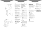
Parts List: 8" Chuck Assembly for Hardinge® CNC Lathes—A2-5 Spindle
Assemblies for Hardinge A2-5, 16C Spindle CNC Lathes:
Model No.
Part Number Description
HM-308-5
HM-308-5Q
SCA 2000308 A25H
SC 2070308 A25H
Standard Chuck - 1.5mm x 60° Master Jaw Serrations
Quick-Change Chuck - 1.5mm x 60° Master Jaw Serrations
Parts List:
1
2
3
4
5
6
7
8
9
Kit
10
11
12
13
14
15A
15B
16
17
18
19
20
21
22
23
24
25
30
31
31A
31B
31C
32
Kit
34
35
36
37
38
39
40
41
Qty
Part Number
Description
6
3
3
6
3
6
1
3
3
1
1
18
3
6
3
1
1
1
3
3
3
1
0
3
1
0
1
3
1
1
1
6
1
1
3
3
3
3
3
1
3
3
MS 0553814
SC 0000115
SC 2000116
MS 0104219
SC 0000110
CE 0001851
replacement N/A
SC 0000108
SCA 0000114
SCA 2000114 S
SC 0000106
MS 0104018
SC 0000105
R 0008044
MS 0104223
SC 0000104
SC 0000132
SCA 0000003
0101428
SCA 0000102
MS 0103518
CE 0000737
CE 0000002
SC 0000131
CE 0000012
NC 0010884
B 0009500 0087
MS 0554219 SS
SC 0000133
CS 0011920
A2 0011920
MS 0104019
SC 0000132
SC 2000721QC
SC 0000722
SC 0000720
SC 0000723
SC 2000721
SC 0000725
SC 0000726
CE 0000004AN
TL 0006615
Socket Set Screw-Flat [M6 x 1x 8mm] (DIN912 12.9, ISO 4762, or ANS B 18.3.1M specs)
"T" Nut Flat - for Metric Serrations - # 22 also needed - Must Use Hardinge "T" Nuts
Soft Top Jaw
Socket Head Cap Screw [M12x1.75 x 25mm] (DIN912 12.9, ISO 4762, or ANS B 18.3.1M specs)
Pin
Fitting, Alemite No. 1851
Chuck Body (Send entire chuck assembly to Hardinge if chuck body is damaged)
Lever
Master Jaws with Metric Serrations (1.5mm x 60°)
Three Master Jaws (9), Shields (12), Escutcheon Pins (13)
Top Plate
Socket Head Cap Screw [M10x1.5 x 20mm] (DIN912 12.9, ISO 4762, or ANS B 18.3.1M specs)
Chip Shield
Escutcheon Pin
Socket Head Cap Screw [M12x1.75x45mm] (DIN912 12.9, ISO 4762, or ANS B 18.3.1M specs)
Chuck Draw Bar for Hardinge A2-5 16C Spindle
Chuck Draw Bar Adapter
Key
Socket Head Cap Screw [1/2"-13x 1-3/4"] (DIN912 12.9, ISO 4762, or ANS B 18.3.1M specs)
Counter Weight
Socket Head Cap Screw [M5 x.8 x 20mm] (DIN912 12.9, ISO 4762, or ANS B 18.3.1M specs)
Nozzle, Alemite No. Z-737
Grease—Chevron Ultra-Duty EP NLGI 2 (Dow Corning BR-2 Plus or Kluber ALTEMP Q NB 50 avail.)
"T"-Nut - Round - for Metric Serrations - # 2 also needed - Must Use Hardinge "T"-Nuts
Eye Bolt, Reid MEB-12
Loctite #242
Safety and Technical Manual
M12x1.75x25mm Set Screw - Balancing Screw - Length may vary
Spindle Adapter – A2-5 to A2-6
Drive Button
Screw for Drive Button
Socket Head Cap Screw (M10 x 1.5 x 25mm) (DIN912 12.9, ISO 4762, or ANS B 18.3.1M specs)
Adapter
Quick-Change Kit includes all parts listed below:
T-Nut
I-Beam
Screw
Top Jaw
Boring Pin
Boring Ring
Spring Plunger
Dowel Pin
Quick-Change Parts
Item
Top Jaws for Hardinge Sure-Grip Chucks—1.5mm x 60° Metric Serrations
Model No.
Part Number 8MSHF
8MMHF
8MSHP
8MMHP
8MH1
Model No.
SC 2000119
SC 2000120
SC 2000116
SC 2000123
SC 2000121
Part Number 8MQP1
SC 2000721
Description (for Standard Chucks)
Standard Height Soft Flat Top Jaw
Medium Height Soft Flat Top Jaw
Standard Height Soft Pointed Top Jaw
Medium Height Soft Pointed Top Jaw
Hard Single Step Top Jaw
Description (for Quick-Change Chucks)
Standard Height Soft Pointed Top Jaw
WARNING:
You must use
Hardinge T-nuts.
(Ignoring this
warning may result
in machine and/or
personal injury)
Hardinge Inc. One Hardinge Drive, Elmira, New York U.S.A. 14902-1507 800.843.8801 www.hardingetooling.com
62
Sure-Grip® Power Chuck Safety and Technical Manual B-87Z
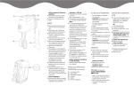
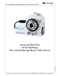
3
MADE IN U.S.A.
MAX. DRAW BAR FORCE
6,500LBS [29KN]
MEASURED STATIC GRIP
FORCE: 10,000LBS [44KN]
MAX. RPMS: 5,500
APPROX WEIGHT:
48LBS [21.8Kg]
GREASE EVERY 24HRS.
2
1
1
o.
LN
DE
MO
8
-30
HM
o.
RIA
LN
SE
Bolt Torque Specs
on pages 119-122
8" Sure-Grip®
Power Chuck for
Hardinge® Lathes
– A2-5 Spindle –
Periodic Safety Inspection—Every 6 Months or After an Accident or Collision
(This inspection should be done after the chuck has been removed from the lathe spindle.)
NOTE: The parts for each jaw location (pin, lever, master jaw, t-nuts and top jaw) should be kept together for reassembly. If assembled into a different
location the chuck will not be balanced and the strokes may not be within specifications.
• Loosen the bolts (4) and raise and slide the standard jaws with the T-nuts (2) from the slot in the master jaw.
Quick-Change Jaw - Loosen bolts (36) one full turn; Remove Quick-Change Top Jaw (37); Again loosen bolt (36) 1/2 turn;
Slide I-beam assembly off (34) (35) (40) master jaw.
• Remove eighteen socket-head cap screws (11) from the top plate.
• Remove the top plate (10). The chip shield (12) does not have to be removed.
• Remove the three master jaws (9).
• Remove three set screws (25) after recording the depth and location. Balance screws may be different lengths and depths and must be replaced in the
same holes and to the same depth.
• Remove 6 set screws (1) which lock in pivot pin (5). Do not remove items (6).
• Remove Pivot Pin (5).
• Remove Lever/counterweight assembly (8) (18) (19).
• Remove Chuck Draw Bar (15A). Do not disassemble item (16) Key.
Check the draw bar, draw bar adapter and all chuck parts, including mounting bolts (4) (11) (14) (17) for hairline cracks,
fissures, and excessive wear. Replace all damaged parts.
WARNING: If the chuck body is damaged, the entire chuck assembly must be sent back to Hardinge for rebuilding.
• Clean all parts.
• Lubricate all moving parts with Chevron Ultra-Duty EP NLGI 2, Dow Corning BR-2-Plus, or Kluber ALTEMP Q NB 50 grease.
• Reassemble parts in the reverse order they were disassembled. Use Loctite #242 (24) on bolts (1)(11)(25).
• Use pressure gun with adapter (20) to grease pivot pin (5) with Chevron Ultra-Duty EP NLGI 2, Dow Corning BR-2-Plus, or Kluber ALTEMP Q NB 50
grease.
• Use pressure gun with adapter (20) to lightly grease master jaws (9) with Chevron Ultra-Duty EP NLGI 2, Dow Corning BR-2-Plus, or Kluber ALTEMP
Q NB 50 grease. Move jaws through their full stroke several times.
• After mounting chuck to machine tool, again grease the master jaws, then move the jaws through their full stroke under power. Grease the jaws again
and cycle under power. This process makes certain all surfaces are lubricated properly.
Hardinge Inc. One Hardinge Drive, Elmira, New York U.S.A. 14902-1507 800.843.8801 www.hardingetooling.com
63
Sure-Grip® Power Chuck Safety and Technical Manual B-87Z
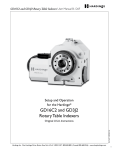
Parts List: 8" Chuck Assembly for Hardinge® Lathes—A2-6 Spindle
Assemblies for Hardinge CNC Lathes:
Model No.
HM-308 HM-308-Q
HMQ-308
HMQ-308-Q
1
2
3
4
5
6
7
8
9
Kit
10
11
12
13
14
15
15a
16
17
18
19
20
21
22
23
24
29
30
Kit
32
33
34
35
36
37
38
39
1.5mm x 60° Master Jaw Serrations
Description
Standard Chuck A2-6, 20C Spindle (T42BB, T51, COBRA® 51, QUEST® & Elite® 8/51, RS 51)
Quick-Change Chuck A2-6, 20C Spindle (T42BB, T51, COBRA® 51, QUEST® & Elite® 8/51, RS 51)
Standard Chuck A2-6, 25C Spindle (QUEST® 10/65, RS 65)
Quick-Change Chuck A2-6, 25C Spindle (QUEST® 10/65, RS 65)
Qty
Part Number
Description
6
3
3
6
3
6
1
3
3
1
1
18
3
6
3
1
1
1
3
3
3
1
0
1
0
1
3
3
1
3
3
3
3
3
1
3
3
MS 0553814
SC 0000115
SC 2000116
MS 0104219
SC 0000110
CE 0001851
replacement N/A
SC 0000108
SCA 0000114
SCA 2000114 S
SC 0000106
MS 0104018
SC 0000105
R 0008044
MS 0104223
SC 0000113
SC 0000576
SCA 0000003
0101428
SCA 0000102
MS 0103518
CE 0000737
CE 0000002
CE 0000012
NC 0010884
B 0009500 0087
SC 0000131
MS 0554219 SS
SC 2000721QC
SC 0000722
SC 0000720
SC 0000723
SC 2000721
SC 0000725
SC 0000726
CE 0000004AN
TL 0006615
Socket Set Screw-Flat [M6 x 1x 8mm] (DIN912 12.9, ISO 4762, or ANS B 18.3.1M specs)
"T" Nut Flat - for Metric Serrations - Item 22 also needed - Must Use Hardinge "T" Nuts
Soft Top Jaw
Socket Head Cap Screw [M12x1.75 x 25mm] (DIN912 12.9, ISO 4762, or ANS B 18.3.1M specs)
Pin
Fitting, Alemite No. 1851
Chuck Body (Send entire chuck assembly to Hardinge if chuck body is damaged)
Lever
Master Jaws with Metric Serrations (1.5mm x 60°)
Three Master Jaws (9), Shields (12), Escutcheon Pins (13)
Top Plate
Socket Head Cap Screw [M10x1.5 x 20mm] (DIN912 12.9, ISO 4762, or ANS B 18.3.1M specs)
Chip Shield
Escutcheon Pin
Socket Head Cap Screw [M12x1.75x45mm] (DIN912 12.9, ISO 4762, or ANS B 18.3.1M specs)
Chuck Draw Bar (CONQUEST® T42BB & T51, COBRA® 51, QUEST® & Elite® 8/51, RS 51)
Chuck Draw Bar (QUEST® 10/65, RS 65)
Key
Socket Head Cap Screw [1/2"-13x 1-3/4"] (DIN912 12.9, ISO 4762, or ANS B 18.3.1M specs)
Counter Weight
Socket Head Cap Screw [M5 x.8 x 20mm] (DIN912 12.9, ISO 4762, or ANS B 18.3.1M specs)
Nozzle, Alemite No. Z-737
Grease—Chevron Ultra-Duty EP NLGI 2 (Dow Corning BR-2 Plus or Kluber ALTEMP Q NB 50 avail.)
Eye Bolt, Reid MEB-12
Loctite #242
Safety and Technical Manual
"T"-Nut - Round - for Metric Serrations - Item 2 also needed - Must Use Hardinge "T"-Nuts
M12x1.75x25mm Set Screw - Balancing Screw - Length may vary
Quick-Change Kit includes all parts listed below
T-Nut
I-Beam
Screw
Top Jaw
Boring Pin
Boring Ring
Spring Plunger
Dowel Pin
Quick-Change Parts
Item
Part Number SCA 2000308 A26H
SC 2070308 A26H
SC 2000308 A26Q
SC 2070308 A26Q
Top Jaws for Hardinge Sure-Grip Chucks —1.5mm x 60° Metric Serrations
Model No.
Part Number 8MSHF
8MMHF
8MSHP
8MMHP
8MH1
SC 2000119
SC 2000120
SC 2000116
SC 2000123
SC 2000121
Model No.
Part Number 8MQP1
SC 2000721
Description (for standard Chucks)
Standard Height Soft Flat Top Jaw
Medium Height Soft Flat Top Jaw
Standard Height Soft Pointed Top Jaw
Medium Height Soft Pointed Top Jaw
Hard Single Step Top Jaw
Description (for Quick-Change Chucks)
Standard Height Soft Pointed Top Jaw
WARNING:
You must use
Hardinge T-nuts.
(Ignoring this
warning may result
in machine and/or
personal injury)
NOTE: Only jaws manufactured by Hardinge Inc. or jaws approved by Hardinge are to be used on Sure-Grip Power Chucks.
Hardinge Inc. One Hardinge Drive, Elmira, New York U.S.A. 14902-1507 800.843.8801 www.hardingetooling.com
64
Sure-Grip® Power Chuck Safety and Technical Manual B-87Z
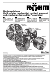
3
MAX. DRAW BAR FORCE
6,500LBS [29KN]
MEASURED STATIC GRIP
FORCE: 10,000LBS [44KN]
MAX. RPMS: 5,500
APPROX WEIGHT:
48LBS [21.8Kg]
GREASE EVERY 24HRS.
2
1
Bolt Torque Specs
on pages 119-122
QUEST 10/65
8" Sure-Grip® Power
Chuck for
Hardinge® Lathes
– A2-6 Spindle –
15a
Periodic Safety Inspection—Every 6 Months or After an Accident or Collision
(This inspection should be done after the chuck has been removed from the lathe spindle)
NOTE: The parts for each jaw location (pin, lever, master jaw, t-nuts and top jaw) should be kept together for reassembly. If assembled into a different
location the chuck will not be balanced and the strokes may not be within specifications.
• Loosen the bolts (4) and raise and slide the standard jaws with the T-nuts (2) from the slot in the master jaw.
Quick-Change Jaw - Loosen bolts (34) one full turn; Remove Quick-Change Top Jaw (35); Again loosen bolt (34) 1/2 turn.
Slide I-beam assembly off (32) (33) (38) master jaw.
• Remove eighteen socket-head cap screws (11) from the top plate.
• Remove the top plate (10). The chip shield (12) does not have to be removed.
• Remove the three master jaws (9).
• Remove three set screws (30) after recording the depth and location. Balance screws may be different lengths and depths and must be replaced in the
same holes and to the same depth.
• Remove six set screws (1) which lock in pivot pin (5). Do not remove items (6).
• Remove Pivot Pin (5).
• Remove Lever/counterweight assembly (8) (18) (19).
• Remove Chuck Draw Bar (15). Do not disassemble item (16) Key.
Check the draw bar, draw bar adapter and all chuck parts, including mounting bolts (4) (11) (14) (17) for hairline cracks,
fissures, and excessive wear. Replace all damaged parts.
WARNING: If the chuck body is damaged, the entire chuck assembly must be sent back to Hardinge for rebuilding.
• Clean all parts.
• Lubricate all moving parts with Chevron Ultra-Duty EP NLGI 2, Dow Corning BR-2-Plus, or Kluber ALTEMP Q NB 50 grease.
• Reassemble parts in the reverse order they were disassembled. Use Loctite #242 (23) on bolts (1)(11)(30).
• Use pressure gun with adapter (20) to grease pivot pin (5) with Chevron Ultra-Duty EP NLGI 2, Dow Corning BR-2-Plus, or Kluber ALTEMP Q NB 50
grease.
• Use pressure gun with adapter (20) to lightly grease master jaws (9) with Chevron Ultra-Duty EP NLGI 2, Dow Corning BR-2-Plus, or Kluber ALTEMP
Q NB 50 grease. Move jaws through their full stroke several times.
• After mounting chuck to machine tool, again grease the master jaws, then move the jaws through their full stroke under power. Grease the jaws again
and cycle under power. This process makes certain all surfaces are lubricated properly.
Hardinge Inc. One Hardinge Drive, Elmira, New York U.S.A. 14902-1507 800.843.8801 www.hardingetooling.com
65
Sure-Grip® Power Chuck Safety and Technical Manual B-87Z
Parts List: 8" Chuck Assembly for Hardinge®-EMAG VL5 Lathes–A2-6 Spindle
Assemblies for Hardinge-EMAG VL5 Lathes:
Model No.
HM-308-6E
HM-308-6EQ
Part Number SC 2200308 A26E
SC 2270308 A26E
Description
Standard Chuck – 1.5mm x 60° Master Jaw Serrations
Quick-Change Chuck – 1.5mm x 60° Master Jaw Serrations
Parts List:
1
2
3
4
5
6
7
8
9
Kit
10
11
12
13
14
16
17
18
19
20
21
22
23
29
30
31
32
33
34
35
36
37
38
39
40
41
42
Kit
43
44
45
46
47
48
49
Qty
Part Number
6
3
3
6
3
9
1
3
3
1
1
18
3
6
3
1
3
3
3
1
0
1
0
3
3
1
1
1
1
1
1
1
1
1
1
1
1
1
3
3
3
3
3
1
3
MS 0553814
SC 0000115
SC 2000116
MS 0104219
SC 0000110
CE 0001851
replacement N/A SC 0000108
SCA 0000114
SCB 2000014 S
SC 0000356
MS 0104018
SC 0000105
R 0008044
MS 0104223
SCA 0000003
MS 0103516
SCA 0000102
MS 0103518
CE 0000737
CE 0000002
CE 0000012
NC 0010884
SC 0000131
MS 0554219 SS
SC 0000391
SC 0000388
CE 1032468
SC 0000600
SC 0000390
B 0009500 0087
SC 0000597
SC 0000587
MS 0573614
SC 0000598
455 0009189
SC 0000592
SC 2000721QC
SC 0000722
SC 0000720
SC 0000723
SC 2000721
SC 0000725
SC 0000726
CE 0000004AN
Description
Socket Set Screw-Flat [M8 x 1.25x 8mm] (DIN912 12.9, ISO 4762, or ANS B 18.3.1M specs)
"T" Nut - for Metric Serrations - .787" spacing for Hard & Soft Jaws - Must Use Hardinge "T" Nuts
Soft Top Jaw
Socket Head Cap Screw [M12x1.75x25mm] (DIN912 12.9, ISO 4762, or ANS B 18.3.1M specs)
Pin
Fitting, Alemite No. 1851
Chuck Body (Send entire chuck assembly to Hardinge if chuck body is damaged)
Lever
Master Jaw with Metric Serrations
Three Master Jaws (9), Shields (12), Escutcheon Pins (13)
Top Plate
Socket Head Cap Screw [M10-1.5x20mm] (DIN912 12.9, ISO 4762, or ANS B 18.3.1M specs)
Chip Shield
Escutcheon Pin
Socket Head Cap Screw [M12-1.75x45mm] (DIN912 12.9, ISO 4762, or ANS B 18.3.1M specs)
Key
Socket Head Cap Screw [M5-.8x12mm] (DIN912 12.9, ISO 4762, or ANS B 18.3.1M specs)
Counter Weight
Socket Head Cap Screw [M5x.8x20mm] (DIN912 12.9, ISO 4762, or ANS B 18.3.1M specs)
Nozzle, Alemite No. Z-737
Grease—Chevron Ultra-Duty EP NLGI 2 (Dow Corning BR-2 Plus or Kluber ALTEMP Q NB 50 avail.)
Eye Bolt
Loctite #242
Round T-Nut
Balancing Set Screw [M12x1.75x25mm] Length of screws may vary
Tool for VL5 EMAG
Chuck Draw Bar (Draw Head)
Stubby Plunger [10-32x15/32]
Draw Bar Link
Nut
Safety and Technical Manual
A2-6 to A2-6 Spindle Adapter Assembly
Cover Plate
Socket Head Set Screw [m6x1x8mm]
Draw Bar Link Adapter
Erickson-Style Spanner Wrench for Installing Link
Mounting Fixture
Quick-Change Kit includes all parts listed below:
T-Nut
I-Beam
Screw
Top Jaw
Boring Pin
Boring Ring
Spring Plunger
Quick-Change Parts
Item
Top Jaws for Hardinge Sure-Grip Chucks—1.5mm x 60° Metric Serrations
Model No.
8MSHF
8MMHF
8MSHP
8MMHP
8MH1
Model No.
8MQP1
Part Number SC 2000119
SC 2000120
SC 2000116
SC 2000123
SC 2000121
Part Number SC 2000721
Description (for standard Chucks)
Standard Height Soft Flat Top Jaw
Medium Height Soft Flat Top Jaw
Standard Height Soft Pointed Top Jaw
Medium Height Soft Pointed Top Jaw
Hard Single Step Top Jaw
Description (for Quick-Change Chucks)
Standard Height Soft Pointed Top Jaw
WARNING:
You must use
Hardinge T-nuts.
(Ignoring this
warning may result
in machine and/or
personal injury)
NOTE: Only jaws manufactured by Hardinge Inc. or jaws approved by Hardinge are to be used on Sure-Grip Power Chucks.
Hardinge Inc. One Hardinge Drive, Elmira, New York U.S.A. 14902-1507 800.843.8801 www.hardingetooling.com
66
Sure-Grip® Power Chuck Safety and Technical Manual B-87Z
QuickChange
Jaw
Bolt Torque Specs
on pages 119-122
37c
8" Sure-Grip® Power
Chuck for Hardinge®
EMAG VL5
Vertical Lathes
– A2-6 Spindle –
Periodic Safety Inspection—Every 6 Months or After an Accident or Collision
(This inspection should be done after the chuck has been removed from the lathe spindle)
NOTE: The parts for each jaw location (pin, lever, master jaw, t-nuts and top jaw) should be kept together for reassembly. If assembled into a different
location the chuck will not be balanced and the strokes may not be within specifications.
• Loosen the bolts (4) and raise and slide the standard jaws with the T-nuts (2) from the slot in the master jaw.
Quick-Change Jaw - Loosen bolts (43) one full turn; Remove Quick-Change Top Jaw (44); Again loosen bolt (43) 1/2 turn.
Slide I-beam assembly off (41) (42) (43) (45) master jaw.
• Remove eighteen socket-head cap screws (11) from the top plate.
• Remove the top plate (10). The chip shield (12) does not have to be removed.
• Remove the three master jaws (9).
• Remove three set screws (30) after recording the depth and location. Balance screws may be different lengths and depths and must be replaced in the
same holes and to the same depth.
• Remove six set screws (1) which lock in pivot pin (5). Do not remove items (6).
• Remove Pivot Pin (5).
• Remove Lever/counterweight assembly (8) (18) (19).
• Remove Chuck Draw Bar assembly (32) (34) (35) (37) (38). Disassembly not required.
Check the draw bar, draw bar adapter and all chuck parts, including mounting bolts (4) (11) (14) (17) (37C) for hairline cracks,
fissures, and excessive wear. Replace all damaged parts.
WARNING: If the chuck body is damaged, the entire chuck assembly must be sent back to Hardinge for rebuilding.
• Clean all parts.
• Lubricate all moving parts with Chevron Ultra-Duty EP NLGI 2, Dow Corning BR-2-Plus, or Kluber ALTEMP Q NB 50 grease.
• Reassemble parts in the reverse order they were disassembled. Use Loctite #242 (22) on bolts (1)(11)(28).
• Use pressure gun with adapter (20) to grease pivot pin (5) with Chevron Ultra-Duty EP NLGI 2, Dow Corning BR-2-Plus, or Kluber ALTEMP Q NB 50
grease.
• Use pressure gun with adapter (20) to lightly grease master jaws (9) with Chevron Ultra-Duty EP NLGI 2, Dow Corning BR-2-Plus, or Kluber ALTEMP
Q NB 50 grease. Move jaws through their full stroke several times.
• After mounting chuck to machine tool, again grease the master jaws, then move the jaws through their full stroke under power. Grease the jaws again
and cycle under power. This process makes certain all surfaces are lubricated properly.
Hardinge Inc. One Hardinge Drive, Elmira, New York U.S.A. 14902-1507 800.843.8801 www.hardingetooling.com
67
Sure-Grip® Power Chuck Safety and Technical Manual B-87Z
Parts List: 8" Chuck Assembly for Hardinge and Other Brand CNC Lathes—A2-6 Spindle
Assemblies for Hardinge Talent® 8/52, SV 200, GS 200 and Other Brand CNC Lathes: B-Version
Item
1
2
3
4
5
6
7
8
9
Kit
10
11
12
13
14
16
17
18
19
20
21
22
23
29
30
31
32
33
34
34a
35
36
Kit
37
38
39
40
41
42
43
44
Part Number SCA 2200308 A26C
SC 2270308 A26C
SC 2200308 A26T
SC 2270308 A26T
Qty
Part Number
6
3
3
6
3
6
1
3
3
1
1
18
3
6
3
1
3
3
3
1
0
1
0
3
3
1
1
1
1
1
1
1
1
3
3
3
3
3
1
3
3
MS 0553814
SC 0000115
SC 2000116
MS 0104219
SC 0000110
CE 0001851
replacement N/A
SC 0000108
SCA 0000114
SCA 2000114 S
SC 0000356
MS 0104018
SC 0000105
R 0008044
MS 0104223
SCA 0000003
0101428
SCA 0000102
MS 0103518
CE 0000737
CE 0000002
CE 0000012
NC 0010884
SC 0000131
MS 0554219 SS
SC 0000391
SC 0000388
CE 1032468
SC 0000389
SC 0000607
SC 0000140
B 0009500 0087
SC 2000721QC
SC 0000722
SC 0000720
SC 0000723
SC 2000721
SC 0000725
SC 0000726
CE 0000004AN
TL 0006615
Description
Standard Chuck – A2-6 Spindle – 1.5mm x 60° Master Jaw Serrations (Other brands)
Quick-Change Chuck – A2-6 Spindle – 1.5mm x 60° Master Jaw Serrations (Other brands)
Standard Chuck for Hardinge Talent 8/52, SV 200 and GS 200 CNC Lathes
Quick-Change Chuck for Hardinge Talent 8/52, SV 200 and GS 200 CNC Lathes
Description
Socket Set Screw-Flat [M6 x 1x 8mm] (DIN912 12.9, ISO 4762, or ANS B 18.3.1M specs)
"T" Nut Flat - Metric Serrations -Item 29 also needed Must Use Hardinge "T" Nuts
Soft Top Jaw
Socket Head Cap Screw [M12x1.75 x 25mm] (DIN912 12.9, ISO 4762, or ANS B 18.3.1M specs)
Pin
Fitting, Alemite No. 1851
Chuck Body (Send entire chuck assembly to Hardinge if chuck body is damaged)
Lever
Master Jaw with Metric Serrations (1.5mm x 60°)
Three Master Jaws (9), Shields (12), Escutcheon Pins (13)
Top Plate
Socket Head Cap Screw [M10x1.5 x 20mm] (DIN912 12.9, ISO 4762, or ANS B 18.3.1M specs)
Chip Shield
Escutcheon Pin
Socket Head Cap Screw [M12x1.75x45mm] (DIN912 12.9, ISO 4762, or ANS B 18.3.1M specs)
Key
Socket Head Cap Screw [1/2"-13x 1-3/4"] (DIN912 12.9, ISO 4762, or ANS B 18.3.1M specs)
Counter Weight
Socket Head Cap Screw [M5 x.8 x 20mm] (DIN912 12.9, ISO 4762, or ANS B 18.3.1M specs)
Nozzle, Alemite No. Z-737
Grease—Chevron Ultra-Duty EP NLGI 2 (Dow Corning BR-2 Plus or Kluber ALTEMP Q NB 50 avail.)
Eye Bolt, Reid MEB-12
Loctite #242
"T"-Nut - Round - for Metric Serrations - Item 2 also needed - Must Use Hardinge "T"-Nuts
M12x1.75x25mm Set Screw - Balancing Screw - Length may vary
Special Wrench - Used to mount the link
Chuck Draw Bar (Draw Head)
Stubby Plunger (#10-32 x 15/32")
Draw Bar Link for other brand CNC lathes
Draw Bar Link for Hardinge (Talent® 8/52, SV 200, GS 200)
Nut
Safety and Technical Manual
Quick-Change Kit includes all parts listed below:
T-Nut
I-Beam
Screw
Top Jaw
Boring Pin
Boring Ring
Spring Plunger
Dowel Pin
Quick-Change Parts
Model No.
CM2-308B-6
CM2-308B-6Q
HM-308-6T
HM-308-6TQ
Top Jaws for Hardinge Sure-Grip Chucks —1.5mm x 60° Metric Serrations
NOTE: Only
jaws manufactured
by Hardinge Inc. or
jaws approved by
Hardinge are to be
used on Sure-Grip
Power Chucks.
Model No.
8MSHF
8MMHF
8MSHP
8MMHP
8MH1
Model No.
8MQP1
Part Number SC 2000119
SC 2000120
SC 2000116
SC 2000123
SC 2000121
Part Number SC 2000721
Description
Standard Height Soft Flat Top Jaw
Medium Height Soft Flat Top Jaw
Standard Height Soft Pointed Top Jaw
Medium Height Soft Pointed Top Jaw
Hard Single Step Top Jaw
Description
Standard Height Soft Pointed Top Jaw
WARNING:
You must use
Hardinge T-nuts.
(Ignoring this
warning may result
in machine and/or
personal injury)
Hardinge Inc. One Hardinge Drive, Elmira, New York U.S.A. 14902-1507 800.843.8801 www.hardingetooling.com
68
Sure-Grip® Power Chuck Safety and Technical Manual B-87Z
Bolt Torque Specs
on pages 119-122
34a
8" Sure-Grip® Power
Chuck for Hardinge
Talent 8/52, SV 200,
SG 200 and Other
CNC Lathes
– A2-6 Spindle –
Periodic Safety Inspection – Every 6 Months or After an Accident or Collision.
(This inspection should be done after the chuck has been removed from the lathe spindle.)
NOTE: The parts for each jaw location (pin, lever, master jaw, t-nuts and top jaw) should be kept together for reassembly. If assemble into a different
location the chuck will not be balanced and the strokes may not be within specifications.
• Loosen the bolts (4) and raise and slide the standard jaws with the T-nuts (2) from the slot in the master jaw.
Quick-Change Jaw - Loosen bolts (39) one full turn; Remove Quick-Change Top Jaw (40); Again loosen bolt (39) 1/2 turn.
Slide I-beam assembly off (37) (38) (43) master jaw.
• Remove eighteen socket-head cap screws (11) from the top plate.
• Remove the top plate (10). The chip shield (12) does not have to be removed.
• Remove the three master jaws (9).
• Remove three set screws (30) after recording the depth and location. Balance screws may be different lengths and depths and must be replaced in the
same holes and to the same depth.
• Remove six set screws (1) which lock in pivot pin (5). Do not remove items (6).
• Remove Pivot Pin (5).
• Remove Lever/counterweight assembly (8) (18) (19).
• Remove Chuck Draw Bar (32). Do not disassemble item (16) Key.
Check the draw bar, draw bar adapter and all chuck parts, including mounting bolts (4) (11) (14) (17) for hairline cracks,
fissures, and excessive wear. Replace all damaged parts.
WARNING: If the chuck body is damaged, the entire chuck assembly must be sent back to Hardinge for rebuilding.
• Clean all parts.
• Lubricate all moving parts with Chevron Ultra-Duty EP NLGI 2, Dow Corning BR-2-Plus, or Kluber ALTEMP Q NB 50 grease.
• Reassemble parts in the reverse order they were disassembled. Use Loctite #242 (23) on bolts (1)(11)(30).
• Use pressure gun with adapter (20) to grease pivot pin (5) with Chevron Ultra-Duty EP NLGI 2, Dow Corning BR-2-Plus, or Kluber ALTEMP Q NB 50
grease.
• Use pressure gun with adapter (20) to lightly grease master jaws (9) with Chevron Ultra-Duty EP NLGI 2, Dow Corning BR-2-Plus, or Kluber ALTEMP
Q NB 50 grease.
• After mounting chuck to machine tool, again grease the master jaws, then move the jaws through their full stroke under power. Grease the jaws again
and cycle under power. This process makes certain all surfaces are lubricated properly.
Hardinge Inc. One Hardinge Drive, Elmira, New York U.S.A. 14902-1507 800.843.8801 www.hardingetooling.com
69
Sure-Grip® Power Chuck Safety and Technical Manual B-87Z
Parts List: 8" Big Bore Chuck Assembly—Other CNC Lathes—A2-6 Spindle
Assemblies
for Other Brand CNC Lathes: C-Version
Model No.
Part Number Description
CM2-308C-6
CM2-308C-6Q
SC 2300308 A26C
SC 2370308 A26C
Standard chuck – A2-6 Spindle – 1.5mm x 60° Master Jaw Serrations
Quick Change Chuck – A2-6 Spindle - 1.5mm x 60° Master Jaw Serrations
Parts List:
1
2
3
4
5
6
7
8
9
10
11
12
13
14
15
16
17
18
19
20
21
22
23
24
25
26
27
33
34
Kit
37
38
39
40
41
42
43
45
Qty
Part Number
Description
6
3
3
6
3
6
1
3
3
1
18
3
6
1
1
1
3
3
3
3
0
1
0
3
1
1
1
1
1
1
3
3
3
3
3
1
3
3
MS 0553814
SC 0000131
SC 2000603
MS 0104219
SC 0000110
CE 0001851
replacement N/A
SC 0000108
SCA 0000114
SC 0000521
MS 0104018
SC 0000105
R 0008044
SC 0000523
CE 1032468
SCA 0000003
MS 0104232
SCA 0000102
MS 0103518
SC 0000115
CE 0000002
CE 0000012
NC 0010884
MS 0554219 SS
SC 0000524
SC 0000522
CE 0000737
SC 0000525
B 0009500 0087
SC 2000727QC
SC 0000722
SC 0000720
SC 0000723
SC 2000727
SC 0000725
SC 0000728
CE 0000004AN
TL 0006615
Socket Set Screw-Flat [M8 x 1.25 x 8mm] (DIN912 12.9, ISO 4762, or ANS B 18.3.1M specs)
"T" Nut Flat - Metric Serrations
Soft Top Jaw
Socket Head Cap Screw [M12x1.75 x 25mm] (DIN912 12.9, ISO 4762, or ANS B 18.3.1M specs)
Pin
Fitting, Alemite No. 1851
Chuck Body (Send entire chuck assembly to Hardinge if chuck body is damaged)
Lever
Master Jaw with Metric Serrations (1.5mm x 60°)
Top Plate
Socket Head Cap Screw [M10x1.5 x 20mm] (DIN912 12.9, ISO 4762, or ANS B 18.3.1M specs)
Chip Shield
Escutcheon Pin
Draw Head
Stubby Plunger (#10-32 x 15/32")
Key
[M12x1.75 x 100mm] SHCS
Counter Weight
Socket Head Cap Screw [M5 x.8 x 20mm] (DIN912 12.9, ISO 4762, or ANS B 18.3.1M specs)
Flat " T" Nut
Grease—Chevron Ultra-Duty EP NLGI 2 (Dow Corning BR-2 Plus or Kluber ALTEMP Q NB 50 avail.)
Eye Bolt, Reid MEB-12
Loctite #242
M12x1.75x25mm Set Screw - Balancing Screw - Length may vary
Nut
Draw Bar Link
Nozzle, Alemite No. Z-737
Special Wrench - Used to mount the link
Safety and Technical Manual
Quick-Change Kit includes all parts listed below
T-Nut
I-Beam
Screw
Top Jaw
Boring Pin
Boring Ring
Spring Plunger
Dowel Pin
Quick-Change Parts
Item
Top Jaws for Sure-Grip Chucks – 1.5mm x 60° Metric Serrations
Model No.
8MSHF
8MMHF
8MSHPL
8MMHP
8MH1
Model No.
8MQP2
Part Number SC 2000119
SC 2000120
SC 2000603
SC 2000123
SC 2000121
Part Number SC 2000727
Description (for standard Chucks)
Standard Height Soft Flat Top Jaw
Medium Height Soft Flat Top Jaw
Standard Height Soft Pointed Top Jaw
Medium Height Soft Pointed Top Jaw
Hard Single Step Top Jaw
Description (for Quick-Change Chucks)
Standard Height Soft Pointed Top Jaw
WARNING:
You must use
Hardinge T-nuts.
(Ignoring this
warning may result
in machine and/or
personal injury)
NOTE: Only jaws manufactured by Hardinge Inc. or jaws approved by Hardinge are to be used on Sure-Grip Power Chucks.
Hardinge Inc. One Hardinge Drive, Elmira, New York U.S.A. 14902-1507 800.843.8801 www.hardingetooling.com
70
Sure-Grip® Power Chuck Safety and Technical Manual B-87Z
Bolt Torque Specs
on pages 119-122
8" Big-Bore
Sure-Grip® Power
Chuck for Other
CNC Lathes
– A2-6 Spindle –
Periodic Safety Inspection—Every 6 Months or After an Accident or Collision.
(This inspection should be done after the chuck has been removed from the lathe spindle.)
NOTE: The parts for each jaw location (pin, lever, master jaw, t-nuts and top jaw) should be kept together for reassembly. If assembled into a different
location the chuck will not be balanced and the strokes may not be within specifications.
• Loosen the bolts (4) and raise and slide the jaws with the T-nuts (2) (20) from the slot in the master jaw.
Quick-Change Jaw - Loosen bolts (39) one full turn; Remove Quick-Change Top Jaw (40); Again loosen bolt (39) 1/2 turn.
Slide I-beam assembly off (37) (38) (43) master jaw.
• Remove the eighteen socket-head cap screws (11) from the top plate.
• Remove the top plate (10).
• Remove the three master jaws (9). It is not necessary to disassembly Items (6) (12) (13).
• Remove three set screws (24), record depth and location. Balance screws may be different lengths and depths and must be replaced in the same holes
and to the same depth.
• Remove six set screws (1) which lock in pivot pin (5). Do not remove items (6).
• Remove Pivot Pin (5).
• Remove Lever/counterweight assembly (8) (18) (19). Do not disassemble.
• Remove Chuck Draw Bar (14). Do not disassemble item (15) (16).
Check all parts including mounting bolts (4) (11) (17) for hairline cracks, fissures, and excessive wear. Replace all damaged parts.
WARNING: If the chuck body is damaged, the entire chuck assembly must be sent back to Hardinge for rebuilding.
• Clean all parts.
• Lubricate all moving parts with Chevron Ultra-Duty EP NLGI 2, Dow Corning BR-2-Plus, or Kluber ALTEMP Q NB 50 grease.
• Reassemble parts in the reverse order they were disassembled. Use Loctite #242 (23) on bolts (1)(11)(24).
• Use pressure gun with adapter (27), grease pivot pin (5) with Chevron Ultra-Duty EP NLGI 2, Dow Corning BR-2-Plus, or Kluber ALTEMP Q NB 50
grease.
• Use pressure gun with adapter (27), lightly grease master jaws (9) with Chevron Ultra-Duty EP NLGI 2, Dow Corning BR-2-Plus, or Kluber ALTEMP Q
NB 50 grease. Move jaws through their full stroke several times.
• After mounting chuck to machine tool, again grease the master jaws, then move the jaws through their full stroke under power. Grease the jaws again
and cycle under power. This process makes certain all surfaces are lubricated properly.
Hardinge Inc. One Hardinge Drive, Elmira, New York U.S.A. 14902-1507 800.843.8801 www.hardingetooling.com
71
Sure-Grip® Power Chuck Safety and Technical Manual B-87Z
Parts List: 8" Chuck Assembly—for Hardinge Lathes—A2-6 Spindle
Assemblies
for Hardinge Talent® 8/66, GS 200/66
Model No.
Part Number Description
HM-308C-6T
HMQ-308C-6T
SC 2300308 A26T
SC 2370308 A26T
Standard chuck – A2-6 Spindle – 1.5mm x 60° Master Jaw Serrations
Quick Change Chuck – A2-6 Spindle - 1.5mm x 60° Master Jaw Serrations
Parts List:
1
2
3
4
5
6
7
8
9
10
11
12
13
14
15
16
17
18
19
20
21
22
23
24
25
26
27
33
34
Kit
37
38
39
40
41
42
43
45
Qty
Part Number
Description
6
3
3
6
3
6
1
3
3
1
18
3
6
1
1
1
3
3
3
3
0
1
0
3
1
1
1
1
1
1
3
3
3
3
3
1
3
3
MS 0553814
SC 0000131
SC 2000603
MS 0104219
SC 0000110
CE 0001851
replacement N/A
SC 0000108
SCA 0000114
SC 0000521
MS 0104018
SC 0000105
R 0008044
SC 0000523
CE 1032468
SCA 0000003
MS 0104232
SCA 0000102
MS 0103518
SC 0000115
CE 0000002
CE 0000012
NC 0010884
MS 0554216 SS
SC 0000524
SC 0000522-T866
CE 0000737
SC 0000525
B 0009500 0087
SC 2000727QC
SC 0000722
SC 0000720
SC 0000723
SC 2000727
SC 0000725
SC 0000728
CE 0000004AN
TL 0006615
Socket Set Screw-Flat [M8 x 1.25 x 8mm] (DIN912 12.9, ISO 4762, or ANS B 18.3.1M specs)
"T" Nut Flat - Metric Serrations
Soft Top Jaw
Socket Head Cap Screw [M12x1.75 x 25mm] (DIN912 12.9, ISO 4762, or ANS B 18.3.1M specs)
Pin
Fitting, Alemite No. 1851
Chuck Body (Send entire chuck assembly to Hardinge if chuck body is damaged)
Lever
Master Jaw with Metric Serrations (1.5mm x 60°)
Top Plate
Socket Head Cap Screw [M10x1.5 x 20mm] (DIN912 12.9, ISO 4762, or ANS B 18.3.1M specs)
Chip Shield
Escutcheon Pin
Draw Head
Stubby Plunger (#10-32 x 15/32")
Key
[M12x1.75 x 100mm] SHCS
Counter Weight
Socket Head Cap Screw [M5 x.8 x 20mm] (DIN912 12.9, ISO 4762, or ANS B 18.3.1M specs)
Flat "T" Nut
Grease—Chevron Ultra-Duty EP NLGI 2 (Dow Corning BR-2 Plus or Kluber ALTEMP Q NB 50 avail.)
Eye Bolt, Reid MEB-12
Loctite #242
M12x1.75x12mm Set Screw - Balancing Screw - Length may vary
Nut
Draw Bar Link
Nozzle, Alemite No. Z-737
Special Wrench - Used to mount the link
Safety and Technical Manual
Quick-Change Kit includes all parts listed below
T-Nut
I-Beam
Screw
Top Jaw
Boring Pin
Boring Ring
Spring Plunger
Dowel Pin
Quick-Change Parts
Item
Top Jaws for Sure-Grip Chucks – 1.5mm x 60° Metric Serrations
Model No.
8MSHF
8MMHF
8MSHPL
8MMHP
8MH1
Model No.
8MQP2
Part Number SC 2000119
SC 2000120
SC 2000603
SC 2000123
SC 2000121
Part Number SC 2000727
Description (for standard Chucks)
Standard Height Soft Flat Top Jaw
Medium Height Soft Flat Top Jaw
Standard Height Soft Pointed Top Jaw
Medium Height Soft Pointed Top Jaw
Hard Single Step Top Jaw
Description (for Quick-Change Chucks)
Standard Height Soft Pointed Top Jaw
WARNING:
You must use
Hardinge T-nuts.
(Ignoring this
warning may result
in machine and/or
personal injury)
NOTE: Only jaws manufactured by Hardinge Inc. or jaws approved by Hardinge are to be used on Sure-Grip Power Chucks.
Hardinge Inc. One Hardinge Drive, Elmira, New York U.S.A. 14902-1507 800.843.8801 www.hardingetooling.com
72
Sure-Grip® Power Chuck Safety and Technical Manual B-87Z
3
IN
DE
MA
1
.
.A
U.S
2
Bolt Torque Specs
on pages 119-122
8" Sure-Grip® Power
Chuck for Hardinge
Talent 8/66 & GS
200/66 CNC Lathes
– A2-6 Spindle –
Periodic Safety Inspection—Every 6 Months or After an Accident or Collision.
(This inspection should be done after the chuck has been removed from the lathe spindle.)
NOTE: The parts for each jaw location (pin, lever, master jaw, t-nuts and top jaw) should be kept together for reassembly. If assembled into a different
location the chuck will not be balanced and the strokes may not be within specifications.
• Loosen the bolts (4) and raise and slide the jaws with the T-nuts (2) (20) from the slot in the master jaw.
Quick-Change Jaw - Loosen bolts (39) one full turn; Remove Quick-Change Top Jaw (40); Again loosen bolt (39) 1/2 turn.
Slide I-beam assembly off (37) (38) (43) master jaw.
• Remove the eighteen socket-head cap screws (11) from the top plate.
• Remove the top plate (10).
• Remove the three master jaws (9). It is not necessary to disassembly Items (6) (12) (13).
• Remove three set screws (24), record depth and location. Balance screws may be different lengths and depths and must be replaced in the same holes
and to the same depth.
• Remove six set screws (1) which lock in pivot pin (5). Do not remove items (6).
• Remove Pivot Pin (5).
• Remove Lever/counterweight assembly (8) (18) (19). Do not disassemble.
• Remove Chuck Draw Bar (14). Do not disassemble item (15) (16).
Check all parts including mounting bolts (4) (11) (17) for hairline cracks, fissures, and excessive wear. Replace all damaged parts.
WARNING: If the chuck body is damaged, the entire chuck assembly must be sent back to Hardinge for rebuilding.
• Clean all parts.
• Lubricate all moving parts with Chevron Ultra-Duty EP NLGI 2, Dow Corning BR-2-Plus, or Kluber ALTEMP Q NB 50 grease.
• Reassemble parts in the reverse order they were disassembled. Use Loctite #242 (23) on bolts (1)(11)(24).
• Use pressure gun with adapter (27), grease pivot pin (5) with Chevron Ultra-Duty EP NLGI 2, Dow Corning BR-2-Plus, or Kluber ALTEMP Q NB 50
grease.
• Use pressure gun with adapter (27), lightly grease master jaws (9) with Chevron Ultra-Duty EP NLGI 2, Dow Corning BR-2-Plus, or Kluber ALTEMP Q
NB 50 grease. Move jaws through their full stroke several times.
• After mounting chuck to machine tool, again grease the master jaws, then move the jaws through their full stroke under power. Grease the jaws again
and cycle under power. This process makes certain all surfaces are lubricated properly.
Hardinge Inc. One Hardinge Drive, Elmira, New York U.S.A. 14902-1507 800.843.8801 www.hardingetooling.com
73
Sure-Grip® Power Chuck Safety and Technical Manual B-87Z
Parts List: 8" Chuck Assembly—for Hardinge Lathes—A2-6 Spindle
Assemblies for Hardinge SR 200 CNC Lathes:
Model No.
Part Number Description
Qty
Part Number
Description
6
3
3
6
3
6
1
3
3
1
18
3
6
1
1
1
3
3
3
3
0
1
0
3
1
1
1
1
1
1
3
3
3
3
3
1
3
3
MS 0553814
SC 0000131
SC 2000603
MS 0104219
SC 0000110
CE 0001851
replacement N/A
SC 0000108
SCA 0000114
SC 0000521
MS 0104018
SC 0000105
R 0008044
SC 0000523
CE 1032468
SCA 0000003
MS 0104232
SCA 0000102
MS 0103518
SC 0000115
CE 0000002
CE 0000012
NC 0010884
MS 0554216 SS
SC 0000524
SC 0000522-SR
CE 0000737
SC 0000525
B 0009500 0087
SC 2000727QC
SC 0000722
SC 0000720
SC 0000723
SC 2000727
SC 0000725
SC 0000728
CE 0000004AN
TL 0006615
Socket Set Screw-Flat [M8 x 1.25 x 8mm] (DIN912 12.9, ISO 4762, or ANS B 18.3.1M specs)
"T" Nut Flat - Metric Serrations
Soft Top Jaw
Socket Head Cap Screw [M12x1.75 x 25mm] (DIN912 12.9, ISO 4762, or ANS B 18.3.1M specs)
Pin
Fitting, Alemite No. 1851
Chuck Body (Send entire chuck assembly to Hardinge if chuck body is damaged)
Lever
Master Jaw with Metric Serrations (1.5mm x 60°)
Top Plate
Socket Head Cap Screw [M10x1.5 x 20mm] (DIN912 12.9, ISO 4762, or ANS B 18.3.1M specs)
Chip Shield
Escutcheon Pin
Draw Head
Stubby Plunger (#10-32 x 15/32")
Key
[M12x1.75 x 100mm] SHCS
Counter Weight
Socket Head Cap Screw [M5 x.8 x 20mm] (DIN912 12.9, ISO 4762, or ANS B 18.3.1M specs)
Flat "T" Nut
Grease—Chevron Ultra-Duty EP NLGI 2 (Dow Corning BR-2 Plus or Kluber ALTEMP Q NB 50 avail.)
Eye Bolt, Reid MEB-12
Loctite #242
M12x1.75x12mm Set Screw - Balancing Screw - Length may vary
Nut
Draw Bar Link
Nozzle, Alemite No. Z-737
Special Wrench - Used to mount the link
Safety and Technical Manual
Quick-Change Kit includes all parts listed below
T-Nut
I-Beam
Screw
Top Jaw
Boring Pin
Boring Ring
Spring Plunger
Dowel Pin
HM-308C-SR
HM-308C-SRQ
SC 2300308 A6SR
SC 2370308 A6SR
Standard chuck – A2-6 Spindle – 1.5mm x 60° Master Jaw Serrations
Quick Change Chuck – A2-6 Spindle - 1.5mm x 60° Master Jaw Serrations
Item
1
2
3
4
5
6
7
8
9
10
11
12
13
14
15
16
17
18
19
20
21
22
23
24
25
26
27
33
34
Kit
37
38
39
40
41
42
43
45
Quick-Change Parts
Parts List:
Top Jaws for Sure-Grip Chucks – 1.5mm x 60° Metric Serrations
Model No.
8MSHF
8MMHF
8MSHPL
8MMHP
8MH1
Model No.
8MQP2
Part Number SC 2000119
SC 2000120
SC 2000603
SC 2000123
SC 2000121
Part Number SC 2000727
Description (for standard Chucks)
Standard Height Soft Flat Top Jaw
Medium Height Soft Flat Top Jaw
Standard Height Soft Pointed Top Jaw
Medium Height Soft Pointed Top Jaw
Hard Single Step Top Jaw
Description (for Quick-Change Chucks)
Standard Height Soft Pointed Top Jaw
WARNING:
You must use
Hardinge T-nuts.
(Ignoring this
warning may result
in machine and/or
personal injury)
NOTE: Only jaws manufactured by Hardinge Inc. or jaws approved by Hardinge are to be used on Sure-Grip Power Chucks.
Hardinge Inc. One Hardinge Drive, Elmira, New York U.S.A. 14902-1507 800.843.8801 www.hardingetooling.com
74
Sure-Grip® Power Chuck Safety and Technical Manual B-87Z
3
DE
MA
IN
1
.A.
U.S
2
Bolt Torque Specs
on pages 119-122
8" Sure-Grip® Power
Chuck for Hardinge
SR 200 CNC Lathes
– A2-6 Spindle –
Periodic Safety Inspection—Every 6 Months or After an Accident or Collision.
(This inspection should be done after the chuck has been removed from the lathe spindle.)
NOTE: The parts for each jaw location (pin, lever, master jaw, t-nuts and top jaw) should be kept together for reassembly. If assembled into a different
location the chuck will not be balanced and the strokes may not be within specifications.
• Loosen the bolts (4) and raise and slide the jaws with the T-nuts (2) (20) from the slot in the master jaw.
Quick-Change Jaw - Loosen bolts (39) one full turn; Remove Quick-Change Top Jaw (40); Again loosen bolt (39) 1/2 turn.
Slide I-beam assembly off (37) (38) (43) master jaw.
• Remove the eighteen socket-head cap screws (11) from the top plate.
• Remove the top plate (10).
• Remove the three master jaws (9). It is not necessary to disassembly Items (6) (12) (13).
• Remove three set screws (24), record depth and location. Balance screws may be different lengths and depths and must be replaced in the same holes
and to the same depth.
• Remove six set screws (1) which lock in pivot pin (5). Do not remove items (6).
• Remove Pivot Pin (5).
• Remove Lever/counterweight assembly (8) (18) (19). Do not disassemble.
• Remove Chuck Draw Bar (14). Do not disassemble item (15) (16).
Check all parts including mounting bolts (4) (11) (17) for hairline cracks, fissures, and excessive wear. Replace all damaged parts.
WARNING: If the chuck body is damaged, the entire chuck assembly must be sent back to Hardinge for rebuilding.
• Clean all parts.
• Lubricate all moving parts with Chevron Ultra-Duty EP NLGI 2, Dow Corning BR-2-Plus, or Kluber ALTEMP Q NB 50 grease.
• Reassemble parts in the reverse order they were disassembled. Use Loctite #242 (23) on bolts (1)(11)(24).
• Use pressure gun with adapter (27), grease pivot pin (5) with Chevron Ultra-Duty EP NLGI 2, Dow Corning BR-2-Plus, or Kluber ALTEMP Q NB 50
grease.
• Use pressure gun with adapter (27), lightly grease master jaws (9) with Chevron Ultra-Duty EP NLGI 2, Dow Corning BR-2-Plus, or Kluber ALTEMP Q
NB 50 grease. Move jaws through their full stroke several times.
• After mounting chuck to machine tool, again grease the master jaws, then move the jaws through their full stroke under power. Grease the jaws again
and cycle under power. This process makes certain all surfaces are lubricated properly.
Hardinge Inc. One Hardinge Drive, Elmira, New York U.S.A. 14902-1507 800.843.8801 www.hardingetooling.com
75
Sure-Grip® Power Chuck Safety and Technical Manual B-87Z
Parts List: 10" Chuck Assembly for Hardinge® Lathes—A2-6 Spindle
Assemblies for Hardinge CNC Lathes: (1.5mm x 60°) Master Jaws
Model No.
Part Number Description
HM310-6
HM310-6Q
HMQ310-6
HMQ310-6Q
SCD 2000310A26H
SCA 2070310A26H
SCA 2000310 A26Q
SCA 2070310A26Q
Standard Chuck for Hardinge CONQUEST® T42BB & 51, Cobra® 51, QUEST® & ELITE® 51, RS 51
Quick-Change Chuck for Hardinge CONQUEST® T42BB & 51, Cobra® 51, QUEST® & ELITE® 51, RS 51
Standard Chuck – A2-6, 25C Spindle for Hardinge QUEST® 10/65, RS 65
Quick-Change Chuck – A2-6, 25C Spindle for Hardinge QUEST® 10/65, RS 65
1
2
3
4
5
6
7
9
10
11
12
13
14
15
16
17
17a
18
19
20
21
21A
21B
21C
23
24
28
29
30
Kit
31
32
33
34
35
36
37
38
Qty Part Number
6
3
3
6
3
9
0
1
3
3
1
18
6
3
3
1
1
1
3
1
1
1
1
6
0
1
3
3
3
1
3
3
3
3
3
3
1
3
MS 0573814
SC 0000165
SC 2000166
MS 0104220
SC 0000160
DV 0010327
CE 0000002
replacement N/A
SC 0000158
SCB 0000164
SCA 0000561
MS 0104021
MS 0303615
MS 0104626
SCA 0000563
SC 0000186
SC 0000562
SCA 0000153
CE 0097248
CE 0000012
SC 0000181
CL 0011920
CL 0011920 01
MS 0104221
NC 0010884
B 0009500 0087
MS 0103519
SC 0000187
MS 0554219 SS
SC 2000701QC
SC 0000702
SC 0000700
SC 0000703
SC 2000701
CE 0000004AN
SC 0000705
SC 0000704
TL 0006615
Description
Socket Set Screw-Flat [M8 x 1.25x 8mm] (DIN912 12.9, ISO 4762, or ANS B 18.3.1M specs)
"T" Nut- for Metric Serrated Jaws - Must Use Hardinge "T" Nuts
Soft Top Jaw
Socket Head Cap Screw [M12x1.75 x 30mm] (DIN912 12.9, ISO 4762, or ANS B 18.3.1M specs)
Pin
Fitting, Alemite No. 1610-BL
Grease—Chevron Ultra-Duty EP NLGI 2 (Dow Corning BR-2 Plus or Kluber ALTEMP Q NB 50 avail.)
10" Chuck Body (Send entire chuck assembly to Hardinge if chuck body is damaged)
Lever
Master Jaw with Metric Serrations (1.5mm x 60°)
Top Plate
Socket Head Cap Screw [M10x1.5 x 35mm] (DIN912 12.9, ISO 4762, or ANS B 18.3.1M specs)
Button Head Screw [M6x1.0x10mm] (DIN912 12.9, ISO 4762, or ANS B 18.3.1M specs)
Socket Head Cap Screw [M16x2x60mm] (DIN912 12.9, ISO 4762, or ANS B 18.3.1M specs)
Chip Shield
Chuck Draw Bar for (CONQUEST® T42BB & 51, Cobra® 51, QUEST® & ELITE® 51, RS 51)
Chuck Draw Bar for (QUEST® 10/65, RS 65)
Key
3/8" x 1.5 Pull Dowel
Eye Bolt, Reid MEB-12
A2-6 to A2-8 Spindle Adapter (not required for QUEST® 10/65)
Drive Button
Drive Button Screw
Socket Head Cap Screw [M12x1.75x35mm] (DIN912 12.9, ISO 4762, or ANS B 18.3.1M specs)
Loctite #242
Safety and Technical Manual
Socket Head Cap Screw [M5x.8x25mm]
Counterweight
Set Screw [M12x1.75x25mm] Balancing Screws – Lengths may vary
Quick-Change Kit includes all parts listed below:
T-Nut
I-Beam
Screw
Top Jaw
Spring Plunger
Boring Pin
Boring Ring
Dowel Pin
Quick-Change Parts
Item
Top Jaws for HardInge Sure-Grip Chucks – 1.5mm x 60° Metric Serrations
Model No.
10MSHF
10MMHF
10MSHP
10MMHP
10MH1
Model No.
10MQP1
Part Number SC 2000169
SC 2000170
SC 2000166
SC 2000173
SC 2000171
Part Number SC 2000701
Description (for standard Chucks)
Standard Height Soft Flat Top Jaw
Medium Height Soft Flat Top Jaw
Standard Height Soft Pointed Top Jaw
Medium Height Soft Pointed Top Jaw
Hard Single Step Top Jaw
Description (for Quick-Change Chucks
Standard Height Soft Pointed Top Jaw
WARNING:
You must use
Hardinge T-nuts.
(Ignoring this
warning may result
in machine and/or
personal injury)
NOTE: Only jaws manufactured by Hardinge Inc. or jaws approved by Hardinge are to be used on Sure-Grip Power Chucks.
Hardinge Inc. One Hardinge Drive, Elmira, New York U.S.A. 14902-1507 800.843.8801 www.hardingetooling.com
76
Sure-Grip® Power Chuck Safety and Technical Manual B-87Z
2
1
Bolt Torque Specs
on pages 119-122
17a
10" Sure-Grip® Power
Chuck for
Hardinge® Lathes
– A2-6 Spindle –
Periodic Safety Inspection—Every 6 Months or After an Accident or Collision
(This inspection should be done after the chuck has been removed from the lathe spindle)
NOTE: The parts for each jaw location (pin, lever, master jaw, t-nuts and top jaw) should be kept together for reassembly. If assembled into a different
location the chuck will not be balanced and the strokes may not be within specifications.
• Loosen the bolts (4) and raise and slide the standard jaws with the T-nuts (2) from the slot in the master jaw.
Quick-Change Jaw - Loosen bolts (33) one full turn; Remove Quick-Change Top Jaw (34); Again loosen bolt (33) 1/2 turn.
Slide I-beam assembly off (31) ( 32) (35) master jaw.
• Remove eighteen socket-head cap screws (13) from the top plate.
• Remove the top plate (12). The chip shield (16) does not have to be removed.
• Remove the three master jaws (11).
• Remove three set screws (30) after recording the depth and location. Balance screws may be different lengths and depths and must be replaced in the
same holes and to the same depth.
• Remove six set screws (1) which lock in pivot pin (5). Do not remove items (6).
• Remove Pivot Pin (5).
• Remove Levers (10).
• Remove Chuck Draw Bar (17). Do not disassemble item (18) Key.
Check the draw bar, draw bar adapter and all chuck parts, including mounting bolts (4) (13) (15) (21B) (28) for hairline cracks,
fissures, and excessive wear. Replace all damaged parts.
WARNING: If the chuck body is damaged, the entire chuck assembly must be sent back to Hardinge for rebuilding.
• Clean all parts.
• Lubricate all moving parts with Chevron Ultra-Duty EP NLGI 2, Dow Corning BR-2-Plus, or Kluber ALTEMP Q NB 50 grease.
• Reassemble parts in the reverse order they were disassembled. Use Loctite #242 (23) on bolts (1)(13)(14)(30).
• Use pressure gun to grease pivot pin (5) with Chevron Ultra-Duty EP NLGI 2, Dow Corning BR-2-Plus, or Kluber ALTEMP Q NB 50 grease.
• Use pressure gun to lightly grease master jaws (11) with Chevron Ultra-Duty EP NLGI 2, Dow Corning BR-2-Plus, or Kluber ALTEMP Q NB 50 grease.
Use the six grease fittings on OD of the chuck body. Move jaws through their full stroke several times.
• After mounting chuck to machine tool, again grease the master jaws, then move the jaws through their full stroke under power. Grease the jaws again
and cycle under power. This process makes certain all surfaces are lubricated properly.
Hardinge Inc. One Hardinge Drive, Elmira, New York U.S.A. 14902-1507 800.843.8801 www.hardingetooling.com
77
Sure-Grip® Power Chuck Safety and Technical Manual B-87Z
Parts List: 10" Chuck Assembly for Hardinge® Lathes—A2-8 Spindle
Assemblies for Hardinge CONQUEST® T51BB & T65 and COBRA® 65 CNC Lathes:
Model No.
Part Number Description
HM310-8
HM310-8Q
SCD 2000310 A28H
SCA 2070310 A28H
Standard Chuck – 1.5mm x 60° Master Jaws
Quick-Change Chuck – 1.5mm x 60° Master Jaws
Parts List:
1
2
3
4
5
6
7
9
10
11
12
13
14
15
16
17
18
19
20
22
23
27
28
29
Kit
30
31
32
33
34
35
36
37
Qty
Part Number
Description
6
3
3
6
3
9
0
1
3
3
1
18
6
3
3
1
1
3
1
0
1
3
3
3
1
3
3
3
3
3
3
1
3
MS 0573814
SC 0000165
SC 2000166
MS 0104220
SC 0000160
DV 0010327
CE 0000002
replacement N/A
SC 0000158
SCB 0000164
SCA 0000156
MS 0104021
MS 0303615
MS 0104626
SCA 0000563
SC 0000154
SCA 0000153
CE 0097248
CE 0000012
NC 0010884
B 0009500 0087
MS 0103520
SC 0000187
MS 0554219 SS
SC 2000701QC
SC 0000702
SC 0000700
SC 0000703
SC 2000701
CE 0000004AN
SC 0000705
SC 0000704
TL 0006615
Socket Set Screw-Flat [M8 x 1.25x 8mm] (DIN912 12.9, ISO 4762, or ANS B 18.3.1M specs)
"T" Nut- for Metric Serrated Jaws - Must Use Hardinge "T" Nuts
Soft Top Jaw
Socket Head Cap Screw [M12x1.75 x 30mm] (DIN912 12.9, ISO 4762, or ANS B 18.3.1M specs)
Pin
Fitting, Alemite No. 1610-BL
Grease—Chevron Ultra-Duty EP NLGI 2 (Dow Corning BR-2 Plus or Kluber ALTEMP Q NB 50 avail.)
10" Chuck Body (Send entire chuck assembly to Hardinge if chuck body is damaged)
Lever
Master Jaw with Metric Serrations (1.5mm x 60°)
Top Plate
Socket Head Cap Screw [M10x1.5 x 35mm] (DIN912 12.9, ISO 4762, or ANS B 18.3.1M specs)
Button Head Screw [M6x1.0x10mm] (DIN912 12.9, ISO 4762, or ANS B 18.3.1M specs)
Socket Head Cap Screw [M16x2x60mm] (DIN912 12.9, ISO 4762, or ANS B 18.3.1M specs)
Chip Shield
Chuck Draw Bar for Hardinge (CONQUEST® T51BB & T65, Cobra® 65)
Key
3/8" x 1.5 Pull Dowel
Eye Bolt, Reid MEB-12
Loctite #242
Safety and Technical Manual
Socket Head Cap Screw [M5x.8x30mm]
Counterweight
Set Screw [M12x1.75x25mm] Balancing Screws – Lengths may vary
Quick-Change Kit includes all parts listed below
T-Nut
I-Beam
Screw
Top Jaw
Spring Plunger
Boring Pin
Boring Ring
Dowel Pin
Quick-Change Parts
Item
Top Jaws for Hardinge Sure-Grip Chucks – 1.5mm x 60° Metric Serrations
Model No.
10MSHF
10MMHF
10MSHP
10MMHP
10MH1
Model No.
10MQP1
Part Number SC 2000169
SC 2000170
SC 2000166
SC 2000173
SC 2000171
Part Number SC 2000701
Description
Standard Height Soft Flat Top Jaw
Medium Height Soft Flat Top Jaw
Standard Height Soft Pointed Top Jaw
Medium Height Soft Pointed Top Jaw
Hard Single Step Top Jaw
Description
Standard Height Soft Pointed Top Jaw
WARNING:
You must use
Hardinge T-nuts.
(Ignoring this
warning may result
in machine and/or
personal injury)
NOTE: Only jaws manufactured by Hardinge Inc. or jaws approved by Hardinge are to be used on Sure-Grip Power Chucks.
Hardinge Inc. One Hardinge Drive, Elmira, New York U.S.A. 14902-1507 800.843.8801 www.hardingetooling.com
78
Sure-Grip® Power Chuck Safety and Technical Manual B-87Z
2
1
Bolt Torque Specs
on pages 119-122
10" Sure-Grip® Power
Chuck for
Hardinge® Lathes
– A2-8 Spindle –
17a
Periodic Safety Inspection—Every 6 Months or After an Accident or Collision
(This inspection should be done after the chuck has been removed from the lathe spindle)
NOTE: The parts for each jaw location (pin, lever, master jaw, t-nuts and top jaw) should be kept together for reassembly. If assembled into a different
location the chuck will not be balanced and the strokes may not be within specifications.
• Loosen the bolts (4) and raise and slide the standard jaws with the T-nuts (2) from the slot in the master jaw.
Quick-Change Jaw - Loosen bolts (33) one full turn; Remove Quick-Change Top Jaw (34); Again loosen bolt (33) 1/2 turn.
Slide I-beam assembly off (31) (32) (35) master jaw.
• Remove eighteen socket-head cap screws (13) from the top plate.
• Remove the top plate (12). The chip shield (16) does not have to be removed.
• Remove the three master jaws (11).
• Remove three set screws (29) after recording the depth and location. Balance screws may be different lengths and depths and must be replaced in the
same holes and to the same depth.
• Remove six set screws (1) which lock in pivot pin (5). Do not remove items (6).
• Remove Pivot Pin (5).
• Remove Levers (10).
• Remove Chuck Draw Bar (17). Do not disassemble item (18) Key.
Check the draw bar, draw bar adapter and all chuck parts, including mounting bolts (4) (13) (16) (28) for hairline cracks,
fissures, and excessive wear. Replace all damaged parts.
WARNING: If the chuck body is damaged, the entire chuck assembly must be sent back to Hardinge for rebuilding.
• Clean all parts.
• Lubricate all moving parts with Chevron Ultra-Duty EP NLGI 2, Dow Corning BR-2-Plus, or Kluber ALTEMP Q NB 50 grease.
• Reassemble parts in the reverse order they were disassembled. Use Loctite #242 (22) on bolts (1)(13)(14)(29).
• Use pressure gun to grease pivot pin (5) with Chevron Ultra-Duty EP NLGI 2, Dow Corning BR-2-Plus, or Kluber ALTEMP Q NB 50 grease.
• Use pressure gun to lightly grease master jaws (11) with Chevron Ultra-Duty EP NLGI 2, Dow Corning BR-2-Plus, or Kluber ALTEMP Q NB 50 grease.
Use the six grease fittings on OD of the chuck body. Move jaws through their full stroke several times.
• After mounting chuck to machine tool, again grease the master jaws, then move the jaws through their full stroke under power. Grease the jaws again
and cycle under power. This process makes certain all surfaces are lubricated properly.
Hardinge Inc. One Hardinge Drive, Elmira, New York U.S.A. 14902-1507 800.843.8801 www.hardingetooling.com
79
Sure-Grip® Power Chuck Safety and Technical Manual B-87Z
Parts List: 10" Chuck Assembly for Hardinge®-EMAG VL5 Lathes–A2-6 Spindle
Assembly for Hardinge-EMAG VL5 Lathes:
Model No.
HM-310-6E
Part Number SC 2200310 A26E
Description
Standard Chuck – 1.5mm x 60° Master Jaw Serrations
Parts List:
Item
1
2
3
4
5
6
7
8
9
10
Kit
11
12
13
14
15
16
17
18
19
21
22
26
27
28
30
31
32
33
34
35
36
Qty
6
3
3
6
3
9
0
1
3
3
1
1
18
6
3
1
1
1
1
1
1
0
3
3
3
1
3
1
1
1
1
1
Part Number
MS 0573814
SC 0000165
SC 2000599
MS 0104220
SC 0000160
DV 0010327
CE 0000002
replacement N/A SC 0000158
SCA 0000164
SCB 2000014 S
SC 0000561
MS 0104021
MS 0303615
MS 0104232
SC 0000563
SC 0000602
SCA 0000003
CE 0097248
CE 0000012
B 0009500 0087
NC 0010884
MS 0103520
SC 0000187
MS 0554219 SS
CE 1032468
MS 0103516
SC 0000587
SC 0000601
SC 0000524
SC 0000592
SC 0000525
Description
Socket Set Screw-Flat [M8x1.25x8mm] (DIN912 12.9, ISO 4762, or ANS B 18.3.1M specs)
"T" Nut - for Metric Serrations - .787" spacing for Hard & Soft Jaws - Must Use Hardinge "T" Nuts
Soft Top Jaw
Socket Head Cap Screw [M12x1.75x25mm] (DIN912 12.9, ISO 4762, or ANS B 18.3.1M specs)
Pin
Fitting, Alemite No. 1610-BL
Grease—Chevron Ultra-Duty EP NLGI 2 (Dow Corning BR-2 Plus or Kluber ALTEMP Q NB 50 avail.)
Chuck Body (Send entire chuck assembly to Hardinge if chuck body is damaged)
Lever
Master Jaw with Metric Serrations
Three Master Jaws (9), Shields (12), Escutcheon Pins (13)
Top Plate
Socket Head Cap Screw [M10-1.5x35mm] (DIN912 12.9, ISO 4762, or ANS B 18.3.1M specs)
Screw [M6-1.0x10mm] (DIN912 12.9, ISO 4762, or ANS B 18.3.1M specs)
Socket Head Cap Screw [M12-1.75x100mm] (DIN912 12.9, ISO 4762, or ANS B 18.3.1M specs)
Chip Shield
Chuck Draw Bar (Draw Head)
Key
3/8" x 1.5 Pull Dowel
Eye Bolt
Safety and Technical Manual
Loctite #242
Socket Head Cap Screw [M5-.8x30mm] (DIN912 12.9, ISO 4762, or ANS B 18.3.1M specs)
Counter Weight
Balancing Set Screw [M12x1.75x25mm] Length of screws may vary
Stubby Plunger [10-32x15/32]
Socket Head Cap Screw [M5x.8x12mm] (DIN912 12.9, ISO 4762, or ANS B 18.3.1M specs)
Cover Plate
Draw Bar Link
Nut
Mounting Fixture
Wrench for Installing Link
WARNING: You must use Hardinge T-nuts. (Ignoring this warning may result in machine and/or personal injury)
Top Jaws for Standard Hardinge Sure-Grip Chucks—1.5mm x 60° Metric Serrations
Model No.
10MSHF
10MMHF
10MSHP
10MHP
10MH1
Part Number SC 2000169
SC 2000170
SC 2000166
SC 2000599
SC 2000171
Description
Standard Height Soft Flat Top Jaw
Medium Height Soft Flat Top Jaw
Standard Height Soft Pointed Top Jaw
Medium Height Soft Pointed Top Jaw
Hard Single Step Top Jaw
NOTE: Only jaws manufactured by Hardinge Inc. or jaws approved by Hardinge are to be used on Sure-Grip Power Chucks.
Hardinge Inc. One Hardinge Drive, Elmira, New York U.S.A. 14902-1507 800.843.8801 www.hardingetooling.com
80
Sure-Grip® Power Chuck Safety and Technical Manual B-87Z
Bolt Torque Specs
on pages 119-122
10" Sure-Grip® Power
Chuck for Hardinge®
EMAG VL5 Vertical
Lathes
– A2-6 Spindle –
Periodic Safety Inspection—Every 6 Months or After an Accident or Collision
(This inspection should be done after the chuck has been removed from the lathe spindle)
NOTE: The parts for each jaw location (pin, lever, master jaw, t-nuts and top jaw) should be kept together for reassembly. If assembled into a different
location the chuck will not be balanced and the strokes may not be within specifications.
• Loosen the bolts (4) and raise and slide the standard jaws with the T-nuts (2) from the slot in the master jaw.
• Remove eighteen socket-head cap screws (11) from the top plate.
• Remove the top plate (10). The chip shield (12) does not have to be removed.
• Remove the three master jaws (9).
• Remove three set screws (28) after recording the depth and location. Balance screws may be different lengths and depths and must be replaced in the
same holes and to the same depth.
• Remove six set screws (1) which lock in pivot pin (5). Do not remove items (6).
• Remove Pivot Pin (5).
• Remove Lever/counterweight assembly (9) (26) (27).
• Remove Chuck Draw Bar assembly (16) (32) (33) (34). Disassembly not required.
Check the draw bar, draw bar adapter and all chuck parts, including mounting bolts (4) (12) (14) (17) for hairline cracks,
fissures, and excessive wear. Replace all damaged parts.
WARNING: If the chuck body is damaged, the entire chuck assembly must be sent back to Hardinge for rebuilding.
• Clean all parts.
• Lubricate all moving parts with Chevron Ultra-Duty EP NLGI 2, Dow Corning BR-2-Plus, or Kluber ALTEMP Q NB 50 grease.
• Reassemble parts in the reverse order they were disassembled. Use Loctite #242 (22) on bolts (1)(11)(28).
• Use pressure gun with adapter (20) to grease pivot pin (5) with Chevron Ultra-Duty EP NLGI 2, Dow Corning BR-2-Plus, or Kluber ALTEMP Q NB 50
grease.
• Use pressure gun with adapter (20) to lightly grease master jaws (10) with Chevron Ultra-Duty EP NLGI 2, Dow Corning BR-2-Plus, or Kluber ALTEMP
Q NB 50 grease. Move jaws through their full stroke several times.
• After mounting chuck to machine tool, again grease the master jaws, then move the jaws through their full stroke under power. Grease the jaws again
and cycle under power. This process makes certain all surfaces are lubricated properly.
Hardinge Inc. One Hardinge Drive, Elmira, New York U.S.A. 14902-1507 800.843.8801 www.hardingetooling.com
81
Sure-Grip® Power Chuck Safety and Technical Manual B-87Z
Parts List: 10" Chuck Assembly for Hardinge® VT100/ VT200 Vertical Lathes – A2-8 & A2-11 Spindle
Assemblies for Hardinge VT100 & VT200 Vertical Lathes:
Model No.
Part Number Description
HVM-310-8
HVM-310-8Q
HVM-310-11
HVM-310-11Q SCC 2000310A28V
SCA 2070310A28V
SCC 2000310A11V
SCA 2070310A11V
Standard Chuck – 1.5mm x 60° Master Jaws (VT100)
Quick-Change Chuck – 1.5mm x 60° Master Jaws (VT100)
Standard Chuck – 1.5mm x 60° Master Jaws (VT200)
Quick-Change Chuck – 1.5mm x 60° Master Jaws (VT200)
Qty
6
3
3
6
3
9
0
3
1
3
3
1
18
6
3
3
1
1
2
1
1
1
1
6
1
1
1
6
0
1
3
3
3
1
1
3
3
3
3
3
3
1
3
Part Number
MS 0573814
SC 0000165
SC 2000166
MS 0104220
SC 0000160
DV 0010327
CE 0000002
SC 0000151
replacement N/A
SC 0000158
SCB 0000164
SCA 0000156
MS 0104021
MS 0313616
MS 0104626
SC 0000185
SC 0000163
SCA 0000153
CE 0097248
CE 0000012
SC 0000182
SC 0000183
SC 0000184
MS 0103822
SC 0000152
CL 0011920 02
CL 0011920 03
MS 0104822
NC 0010884
B 0009500 0087
MS 0103519
SC 0000187
MS 0554219 SS
OR 0005254
SC 2000701QC
SC 0000702
SC 0000700
SC 0000703
SC 2000701
CE 0000004AN
SC 0000705
SC 0000704
TL 0006615
Description
Socket Set Screw-Flat [M8 x 1.25x 8mm] (DIN912 12.9, ISO 4762, or ANS B 18.3.1M specs)
"T" Nut - for Metric Serrated Jaws - Must Use Hardinge "T" Nuts
Soft Top Jaw
Socket Head Cap Screw [M12x1.75 x 30mm] (DIN912 12.9, ISO 4762, or ANS B 18.3.1M specs)
Pin
Fitting, Alemite No. 1610-BL
Grease—Chevron Ultra-Duty EP NLGI 2 (Dow Corning BR-2 Plus or Kluber ALTEMP Q NB 50 avail.)
"T" Nut - Must Use Hardinge "T" Nuts For Inch Jaws
10" Chuck Body (Send entire chuck assembly to Hardinge if chuck body is damaged)
Lever
Master Jaw with Metric Serrations (1.5mm x 60°)
Top Plate
Socket Head Cap Screw [M10x1.5 x 35mm] (DIN912 12.9, ISO 4762, or ANS B 18.3.1M specs)
Flat Head Screw [M6x1.0x12mm] (DIN912 12.9, ISO 4762, or ANS B 18.3.1M specs)
Socket Head Cap Screw [M16x2x60mm] (DIN912 12.9, ISO 4762, or ANS B 18.3.1M specs)
Chip Shield
Chuck Draw Bar
Chuck Key
3
/8" x 1.5 Pull Dowel
Eye Bolt, Reid MEB-12
Draw Bar for Hardinge CONQUEST®VT-100 (4.125"/104.7mm Long)
Draw Bar for Hardinge CONQUEST®VT-200 (6.00"/152.4mm Long)
Draw Bar Bushing
Socket Head Cap Screw [M8x1.25 x 40mm] (DIN912 12.9, ISO 4762, or ANS B 18.3.1M specs)
A2-11 to A2-8 Spindle Adapter (Only for SCB 2000310A11V)
Drive Button
Drive Button Screw
Socket Head Cap Screw [M18x2.5x40mm] (DIN912 12.9, ISO 4762, or ANS B 18.3.1M specs)
Loctite #242
Safety and Technical Manual
Set Screw [M5x.8x25mm]
Counterweight
Set Screw [M12x1.75x25mm] Balancing Screws – Lengths may vary
O Ring [3-1/4 ID 1/16 CS]
Quick-Change Kit includes all parts listed below:
T-Nut
I-Beam
Screw
Top Jaw
Spring Plunger
Boring Pin
Boring Ring
Dowel Pin
Quick-Change Parts
Item
1
2
3
4
5
6
7
8
9
10
11
12
13
14
15
16
17
18
19
20
21
21A
22
23
25
25A
25B
25C
26
28
32
33
34
35
Kit
36
37
38
39
40
41
42
43
Top Jaws for Hardinge Sure-Grip Chucks – 1.5mm x 60° Metric Serrations
NOTE: Only
jaws manufactured
by Hardinge Inc. or
jaws approved by
Hardinge are to be
used on Sure-Grip
Power Chucks.
Model No.
10MSHF
10MMHF
10MSHP
10MMHP
10MH1
Model No.
10MQP1
Part Number SC 2000169
SC 2000170
SC 2000166
SC 2000173
SC 2000171
Part Number SC 2000701
Description (for standard Chucks)
Standard Height Soft Flat Top Jaw
Medium Height Soft Flat Top Jaw
Standard Height Soft Pointed Top Jaw
Medium Height Soft Pointed Top Jaw
Hard Single Step Top Jaw
Description
Standard Height Soft Pointed Top Jaw
WARNING:
You must use
Hardinge T-nuts.
(Ignoring this
warning may result
in machine and/or
personal injury)
Hardinge Inc. One Hardinge Drive, Elmira, New York U.S.A. 14902-1507 800.843.8801 www.hardingetooling.com
82
Sure-Grip® Power Chuck Safety and Technical Manual B-87Z
3
3
2
1
Bolt Torque Specs
on pages 119-122
10" Sure-Grip® Power
Chuck for Hardinge®
VT100/VT200
Vertical Lathes
A2-8/A2-11 Spindles
Periodic Safety Inspection—Every 6 Months or After an Accident or Collision
(This inspection should be done after the chuck has been removed from the lathe spindle)
NOTE: The parts for each jaw location (pin, lever, master jaw, t-nuts and top jaw) should be kept together for reassembly. If assembled into a different
location the chuck will not be balanced and the strokes may not be within specifications.
• Loosen the bolts (4) and raise and slide the standard jaws with the T-nuts (2) from the slot in the master jaw.
Quick-Change Jaw - Loosen bolts (33) one full turn; Remove Quick-Change Top Jaw (34); Again loosen bolt (33) 1/2 turn.
Slide I-beam assembly off (31) (32) (35) master jaw.
• Remove eighteen socket head cap screws (13) from the top plate.
• Remove the top plate (12). The chip shield (16) does not have to be removed.
• Remove the three master jaws (11).
• Remove three set screws (32) after recording the depth and location. Balance screws may be different lengths and depths and must be replaced in the
same holes and to the same depth.
• Remove six set screws (1) which lock in pivot pin (5). Do not remove items (6).
• Remove Pivot Pin (5).
• Remove Levers (10).
• Remove Chuck Draw Bar (17). Do not disassemble item (18) Key.
Check the draw bar, draw bar adapter and all chuck parts, including mounting bolts (4) (13) (16) (28) for hairline cracks,
fissures, and excessive wear. Replace all damaged parts.
WARNING: If the chuck body is damaged, the entire chuck assembly must be sent back to Hardinge for rebuilding.
• Clean all parts.
• Lubricate all moving parts with Chevron Ultra-Duty EP NLGI 2, Dow Corning BR-2-Plus, or Kluber ALTEMP Q NB 50 grease.
• Reassemble parts in the reverse order they were disassembled. Use Loctite #242 (26) on bolts (1)(13)(14)(32)(34).
• Use pressure gun to grease pivot pin (5) with Chevron Ultra-Duty EP NLGI 2, Dow Corning BR-2-Plus, or Kluber ALTEMP Q NB 50 grease.
• Use pressure gun to lightly grease master jaws (11) with Chevron Ultra-Duty EP NLGI 2, Dow Corning BR-2-Plus, or Kluber ALTEMP Q NB 50 grease.
Use the six grease fittings on OD of the chuck body. Move jaws through their full stroke several times.
• After mounting chuck to machine tool, again grease the master jaws, then move the jaws through their full stroke under power. Grease the jaws again
and cycle under power. This process makes certain all surfaces are lubricated properly.
Hardinge Inc. One Hardinge Drive, Elmira, New York U.S.A. 14902-1507 800.843.8801 www.hardingetooling.com
83
Sure-Grip® Power Chuck Safety and Technical Manual B-87Z
Parts List: 10" Chuck Assembly for Hardinge and Other CNC Lathes—A2-8 Spindle—B-Version
Assemblies for Hardinge Talent 10/78, GS 250 and Other brand CNC Lathes: B-Version
Model No.
Part Number Description
CM2-310B-8
CM2-310B-8Q
TM2-310B-8
TM2-310B-8Q
SCC 2200310 A28C
SCA 2270310 A28C
SC 2200310 A28T
SC 2270310 A28T
Standard Chuck – A2-8 Spindle – 1.5mm x 60° Master Jaw Serrations (Other brands)
Quick-Change Chuck – A2-8 Spindle – 1.5mm x 60° Master Jaw Serrations (Other brands)
Standard Chuck for Hardinge Talent 10/78 and GS 250 CNC Lathes
Quick-Change Chuck for Hardinge Talent 10/78 and GS 250 CNC Lathes
Parts List:
Qty
6
3
3
6
3
9
0
3
1
3
3
1
18
6
3
6
3
1
3
1
0
1
3
3
1
1
1
1
1
1
1
3
3
3
3
3
3
1
3
Part Number
MS 0573814
SC 0000165
SC 2000166
MS 0104220
SC 0000160
DV 0010327
CE 0000002
SC 0000187
replacement N/A
SC 0000458
SCB 0000164
SCA 0000456
MS 0104021
MS 0303615
SCA 0000455
0101836
MS 0104626
SCA 0000153
CE 0097248
CE 0000012
NC 0010884
B 0009500 0087
MS 0103520
MS 0554219 SS
SC 0000488
CE 2520531
SC 0000489
SC 0000811
SC 0000490
SC 0000491
SC 2000701QC
SC 0000702
SC 0000700
SC 0000703
SC 2000701
CE 0000004AN
SC 0000705
SC 0000704
TL 0006615
Description
Socket Set Screw-Flat [M8 x 1.25x 8mm] (DIN912 12.9, ISO 4762, or ANS B 18.3.1M specs)
"T" Nut for Metric Serrated Jaws - Must Use Hardinge "T" Nuts
Soft Top Jaw
Socket Head Cap Screw [M12x1.75 x 30mm] (DIN912 12.9, ISO 4762, or ANS B 18.3.1M specs)
Pin
Fitting, Alemite No. 1610-BL
Grease—Chevron Ultra-Duty EP NLGI 2 (Dow Corning BR-2 Plus or Kluber ALTEMP Q NB 50 avail.)
Counterweight
10" Chuck Body (Send entire chuck assembly to Hardinge if chuck body is damaged)
Lever
Master Jaw with Metric Serrations (1.5mm x 60°)
Top Plate
Socket Head Cap Screw [M10x1.5 x 35mm] (DIN912 12.9, ISO 4762, or ANS B 18.3.1M specs)
Button Head Screw [M6x1.0x10mm] (DIN912 12.9, ISO 4762, or ANS B 18.3.1M specs)
Chip Shield
Socket head Cap Screw (5/8"-011 x 2-1/4") (DIN912 12.9, ISO 4762, or ANS B 18.3.1M specs)
Socket Head Cap Screw [M16x2x60mm] (DIN912 12.9, ISO 4762, or ANS B 18.3.1M specs)
Key
3
/8" x 1.5 Pull Dowel
Eye Bolt, Reid MEB-12
Loctite #242
Safety and Technical Manual
Socket Head Cap Screw [M5x.8x30mm]
Set Screw [M12x1.75x25mm] Balancing Screws – Lengths may vary
Chuck Draw Bar (Draw Head) A2-8 Spindle
Stubby Plunger (1/4"-20 x 1")
Draw Bar Link
Draw Bar Link for Hardinge (Talent 10/78, GS 250)
Nut
Special Wrench for Link
Quick-Change Kit includes all parts listed below:
T-Nut
I-Beam
Screw
Top Jaw
Spring Plunger
Boring Pin
Boring Ring
Dowel Pin
Quick-Change Parts
Item
1
2
3
4
5
6
7
8
9
10
11
12
13
14
15
16
17
18
19
20
22
23
27
28
29
30
31
31a
32
33
Kit
36
37
38
39
40
41
42
43
Top Jaws for Hardinge Sure-Grip Chucks – 1.5mm x 60° Metric Serrations
NOTE: Only
jaws manufactured
by Hardinge Inc. or
jaws approved by
Hardinge are to be
used on Sure-Grip
Power Chucks.
Model No.
10MSHF
10MMHF
10MSHP
10MMHP
10MH1
Model No.
10MQP1
Part Number SC 2000169
SC 2000170
SC 2000166
SC 2000173
SC 2000171
Part Number SC 2000701
Description
Standard Height Soft Flat Top Jaw
Medium Height Soft Flat Top Jaw
Standard Height Soft Pointed Top Jaw
Medium Height Soft Pointed Top Jaw
Hard Single Step Top Jaw
Description
Standard Height Soft Pointed Top Jaw
WARNING:
You must use
Hardinge T-nuts.
(Ignoring this
warning may result
in machine and/or
personal injury)
Hardinge Inc. One Hardinge Drive, Elmira, New York U.S.A. 14902-1507 800.843.8801 www.hardingetooling.com
84
Sure-Grip® Power Chuck Safety and Technical Manual B-87Z
Bolt Torque Specs
on pages 119-122
31a
10" Sure-Grip® Power
Chuck for Hardinge
Talent 10/78, GS 250
and Other CNC Lathes
A2-8 Spindle B-Version
Periodic Safety Inspection—Every 6 Months or After an Accident or Collision
(This inspection should be done after the chuck has been removed from the lathe spindle)
NOTE: The parts for each jaw location (pin, lever, master jaw, t-nuts and top jaw) should be kept together for reassembly. If assembled into a different
location the chuck will not be balanced and the strokes may not be within specifications.
• Loosen the bolts (4) and raise and slide the standard jaws with the T-nuts (2) from the slot in the master jaw.
Quick-Change Jaw - Loosen bolts (33) one full turn; Remove Quick-Change Top Jaw (34); Again loosen bolt (33) 1/2 turn.
Slide I-beam assembly off (31) (32) (35) master jaw.
• Remove eighteen socket-head cap screws (13) from the top plate.
• Remove the top plate (12). The chip shield (15) does not have to be removed.
• Remove the three master jaws (11).
• Remove three set screws (28) after recording the depth and location. Balance screws may be different lengths and depths and must be replaced in the
same holes and to the same depth.
• Remove six set screws (1) which lock in pivot pin (5). Do not remove items (6).
• Remove Pivot Pin (5).
• Remove Levers (10).
• Remove Chuck Draw Bar (29). Do not disassemble item (18) Key.
Check the draw bar, draw bar adapter and all chuck parts, including mounting bolts (4) (13) (16) (28) for hairline cracks,
fissures, and excessive wear. Replace all damaged parts.
WARNING: If the chuck body is damaged, the entire chuck assembly must be sent back to Hardinge for rebuilding.
• Clean all parts.
• Lubricate all moving parts with Chevron Ultra-Duty EP NLGI 2, Dow Corning BR-2-Plus, or Kluber ALTEMP Q NB 50 grease.
• Reassemble parts in the reverse order they were disassembled. Use Loctite #242 (22) on bolts (1)(13)(14)(29).
• Use pressure gun to grease pivot pin (5) with Chevron Ultra-Duty EP NLGI 2, Dow Corning BR-2-Plus, or Kluber ALTEMP Q NB 50 grease.
• Use pressure gun to lightly grease master jaws (11) with Chevron Ultra-Duty EP NLGI 2, Dow Corning BR-2-Plus, or Kluber ALTEMP Q NB 50 grease.
Use the six grease fittings on OD of the chuck body. Move jaws through their full stroke several times.
• After mounting chuck to machine tool, again grease the master jaws, then move the jaws through their full stroke under power. Grease the jaws again
and cycle under power. This process makes certain all surfaces are lubricated properly.
Hardinge Inc. One Hardinge Drive, Elmira, New York U.S.A. 14902-1507 800.843.8801 www.hardingetooling.com
85
Sure-Grip® Power Chuck Safety and Technical Manual B-87Z
Parts List: 10" Chuck Assembly for Other CNC Lathes—A2-8 Spindle—Large Bore
Assemblies for Other brand Large-Bore CNC Lathes: C-Version
Model No.
Part Number Description
CM2-310C-8
CM2-310C-8Q
SCA 2300310 A28C
SCA 2270310 A28C
Standard Chuck, A2-8 Spindle – 1.5mm x 60° Master Jaw Serrations
Quick-Change Chuck, A2-8 Spindle - 1.5mm x 60° Master Jaw Serrations
Parts List:
Qty
6
3
3
6
3
9
0
1
1
3
3
1
18
6
3
3
1
1
3
1
1
0
1
3
1
3
3
1
1
3
3
3
3
3
3
1
3
Part Number
MS 0573814
SC 0000165
SC 2000166
MS 0104220
SC 0000160
DV 0010327
CE 0000002
CE 2520531
replacement N/A
SC 0000458
SCB 0000164
SC 0000550
MS 0104021
MS 0303615
MS 0104626
SC 0000555
SC 0000552
SCA 0000153
CE 0097248
CE 0000012
SC 0000553
NC 0010884
SC 0000554
MS 0554219 SS
B 0009500 0087
MS 0103520
SC 0000187
SC 0000556
SC2000706QC
SC 0000702
SC 0000700
SC 0000703
SC 2000706
CE 0000004AN
SC 0000705
SC 0000707
TL 0006615
Description
Socket Set Screw-Flat [M8 x 1.25x 8mm] (DIN912 12.9, ISO 4762, or ANS B 18.3.1M specs)
"T" Nut for Metric Serrated Jaws - Must Use Hardinge "T" Nuts
Soft Top Jaw
Socket Head Cap Screw [M12x1.75 x 30mm] (DIN912 12.9, ISO 4762, or ANS B 18.3.1M specs)
Pin
Fitting, Alemite No. 1610-BL
Grease—Chevron Ultra-Duty EP NLGI 2 (Dow Corning BR-2 Plus or Kluber ALTEMP Q NB 50 avail.)
Stubby Plunger (1/4"-20 x 1")
10" Chuck Body (Send entire chuck assembly to Hardinge if chuck body is damaged)
Lever
Master Jaw with Metric Serrations (1.5mm x 60°)
Top Plate
Socket Head Cap Screw [M10x1.5 x 35mm] (DIN912 12.9, ISO 4762, or ANS B 18.3.1M specs)
Button Head Screw [M6x1.0x10mm] (DIN912 12.9, ISO 4762, or ANS B 18.3.1M specs)
Socket Head Cap Screw [M16x2x60mm] (DIN912 12.9, ISO 4762, or ANS B 18.3.1M specs)
Chip Shield
Chuck Draw Bar (Draw Head) A2-8 Spindle
Key
3/8" x 1.5 Pull Dowel
Eye Bolt, Reid MEB-12
Draw Bar Link
Loctite #242
Nut
Set Screw [M12x1.75x25mm] Balancing Screws – Lengths may vary
Safety and Technical Manual
Socket Head Cap Screw [M5x.8x30mm]
Counterweight
Special Wrench for Link
Quick-Change Kit includes all parts listed below:
T-Nut
I-Beam
Screw
Top Jaw
Spring Plunger
Boring Pin
Boring Ring
Dowel Pin
Quick-Change Parts
Item
1
2
3
4
5
6
7
8
9
10
11
12
13
14
15
16
17
18
19
20
21
22
23
24
26
27
28
29
Kit
36
37
38
39
40
41
42
43
Top Jaws for Hardinge Sure-Grip Chucks – 1.5mm x 60° Metric Serrations
Model No.
10MSHF
10MMHF
10MSHP
10MMHP
10MH1
Model No.
10MQP2
Part Number SC 2000169
SC 2000170
SC 2000166
SC 2000173
SC 2000171
Part Number SC 2000706
Description (for standard Chucks)
Standard Height Soft Flat Top Jaw
Medium Height Soft Flat Top Jaw
Standard Height Soft Pointed Top Jaw
Medium Height Soft Pointed Top Jaw
Hard Single Step Top Jaw
Description (for Quick-Change Chucks)
Standard Height Soft Pointed Top Jaw
WARNING:
You must use
Hardinge T-nuts.
(Ignoring this
warning may result
in machine and/or
personal injury)
NOTE: Only jaws manufactured by Hardinge Inc. or jaws approved by Hardinge are to be used on Sure-Grip Power Chucks.
Hardinge Inc. One Hardinge Drive, Elmira, New York U.S.A. 14902-1507 800.843.8801 www.hardingetooling.com
86
Sure-Grip® Power Chuck Safety and Technical Manual B-87Z
Bolt Torque Specs
on pages 119-122
10" Sure-Grip® Power
Chuck for
Other CNC Lathes
– A2-8 Spindle –
C-Version
Periodic Safety Inspection – Every 6 Months or After an Accident or Collision.
(This inspection should be done after the chuck has been removed from the lathe spindle.)
NOTE: The parts for each jaw location (pin, lever, master jaw, t-nuts and top jaw) should be kept together for reassembly. If assembled into a different
location the chuck will not be balanced and the strokes may not be within specifications.
• Loosen the bolts (4) and raise and slide the standard jaws with the T-nuts (2) from the slot in the master jaw.
Quick-Change Jaw - Loosen bolts (33) one full turn; Remove Quick-Change Top Jaw (34); Again loosen bolt (33) 1/2 turn.
Slide I-beam assembly off (31) (32) (35) master jaw.
• Remove eighteen socket-head cap screws (13) from the top plate.
• Remove the top plate (12). The chip shield (16) does not have to be removed.
• Remove the three master jaws (11).
• Remove three set screws (24) after recording the depth and location. Balance screws may be different lengths and depths and must be replaced in the
same holes and to the same depth.
• Remove six set screws (1) which lock in pivot pin (5). Do not remove items (6).
• Remove Pivot Pin (5).
• Remove Levers (10).
• Remove Chuck Draw Bar (17). Do not disassemble item (18) Key.
Check the draw bar, draw bar adapter and all chuck parts, including mounting bolts (4) (13) (16) (28) for hairline cracks,
fissures, and excessive wear. Replace all damaged parts.
WARNING: If the chuck body is damaged, the entire chuck assembly must be sent back to Hardinge for rebuilding.
• Clean all parts.
• Lubricate all moving parts with Chevron Ultra-Duty EP NLGI 2, Dow Corning BR-2-Plus, or Kluber ALTEMP Q NB 50 grease.
• Reassemble parts in the reverse order they were disassembled. Use Loctite #242 (22) on bolts (1)(13)(14)(24).
• Use pressure gun to grease pivot pin (5) with Chevron Ultra-Duty EP NLGI 2, Dow Corning BR-2-Plus, or Kluber ALTEMP Q NB 50 grease.
• Use pressure gun to lightly grease master jaws (11) with Chevron Ultra-Duty EP NLGI 2, Dow Corning BR-2-Plus, or Kluber ALTEMP Q NB 50 grease.
Use the six grease fittings on OD of the chuck body. Move jaws through their full stroke several times.
• After mounting chuck to machine tool, again grease the master jaws, then move the jaws through their full stroke under power. Grease the jaws again
and cycle under power. This process makes certain all surfaces are lubricated properly.
Hardinge Inc. One Hardinge Drive, Elmira, New York U.S.A. 14902-1507 800.843.8801 www.hardingetooling.com
87
Sure-Grip® Power Chuck Safety and Technical Manual B-87Z
Parts List: 10" Chuck Assembly for Hardinge SR 250 CNC Lathes—A2-8 Spindle
Assemblies for SR 250 CNC Lathes:
Model No.
Part Number Description
HM-310-SR
HM-310-SRQ
SC 2300310 A8SR
SC 2370310 A8SR
Standard Chuck – A2-8 Spindle – 1.5mm x 60° Master Jaw Serrations
Quick-Change Chuck – A2-8 Spindle – 1.5mm x 60° Master Jaw Serrations
Parts List:
Qty
6
3
3
6
3
9
0
1
1
3
3
1
18
6
3
3
1
1
3
1
1
0
1
3
1
3
3
1
6
1
3
3
3
3
3
3
1
3
Part Number
MS 0573814
SC 0000165
SC 2000166
MS 0104220
SC 0000160
DV 0010327
CE 0000002
CE 2520531
replacement N/A
SC 0000458
SCB 0000164
SC 0000550
MS 0104021
MS 0303615
MS 0104626
SC 0000555
SC 0000552
SCA 0000153
CE 0097248
CE 0000012
SC 0000553-SR
NC 0010884
SC 0000554
MS 0554216 SS
B 0009500 0087
MS 0103520
SC 0000187
SC 0000556
0101836
SC 2000701QC
SC 0000702
SC 0000700
SC 0000703
SC 2000701
CE 0000004AN
SC 0000705
SC 0000704
TL 0006615
Description
Socket Set Screw-Flat [M8 x 1.25x 8mm] (DIN912 12.9, ISO 4762, or ANS B 18.3.1M specs)
"T" Nut for Metric Serrated Jaws - Must Use Hardinge "T" Nuts
Soft Top Jaw
Socket Head Cap Screw [M12x1.75 x 30mm] (DIN912 12.9, ISO 4762, or ANS B 18.3.1M specs)
Pin
Fitting, Alemite No. 1610-BL
Grease—Chevron Ultra-Duty EP NLGI 2 (Dow Corning BR-2 Plus or Kluber ALTEMP Q NB 50 avail.)
Stubby Plunger (1/4"-20 x 1")
10" Chuck Body (Send entire chuck assembly to Hardinge if chuck body is damaged)
Lever
Master Jaw with Metric Serrations (1.5mm x 60°)
Top Plate
Socket Head Cap Screw [M10x1.5 x 35mm] (DIN912 12.9, ISO 4762, or ANS B 18.3.1M specs)
Button Head Screw [M6x1.0x10mm] (DIN912 12.9, ISO 4762, or ANS B 18.3.1M specs)
Socket Head Cap Screw [M16x2x60mm] (DIN912 12.9, ISO 4762, or ANS B 18.3.1M specs)
Chip Shield
Chuck Draw Bar (Draw Head) A2-8 Spindle
Key
3/8" x 1.5 Pull Dowel
Eye Bolt, Reid MEB-12
Draw Bar Link for Hardinge (SR 250)
Loctite #242
Nut
Set Screw [M12x1.75x12mm] Balancing Screws – Lengths may vary
Safety and Technical Manual
Socket Head Cap Screw [M5x.8x30mm]
Counterweight
Special Wrench for Link
Socket head Cap Screw {5/8"-11 x 2-1/4"} (DIN912 12.9, ISO 4762, or ANS B 18.3.1M specs)
Quick-Change Kit includes all parts listed below:
T-Nut
I-Beam
Screw
Top Jaw
Spring Plunger
Boring Pin
Boring Ring
Dowel Pin
Quick-Change Parts
Item
1
2
3
4
5
6
7
8
9
10
11
12
13
14
15
16
17
18
19
20
21
22
23
24
26
27
28
29
34
Kit
36
37
38
39
40
41
42
43
Top Jaws for Hardinge Sure-Grip Chucks – 1.5mm x 60° Metric Serrations
NOTE: Only
jaws manufactured by Hardinge Inc. or
jaws approved by
Hardinge are to be
used on Sure-Grip
Power Chucks. Model No.
10MSHF
10MMHF
10MSHP
10MMHP
10MH1
Model No.
10MQP1
Part Number SC 2000169
SC 2000170
SC 2000166
SC 2000173
SC 2000171
Part Number SC 2000701
Description
Standard Height Soft Flat Top Jaw
Medium Height Soft Flat Top Jaw
Standard Height Soft Pointed Top Jaw
Medium Height Soft Pointed Top Jaw
Hard Single Step Top Jaw
Description
Standard Height Soft Pointed Top Jaw
WARNING:
You must use
Hardinge T-nuts.
(Ignoring this
warning may result
in machine and/or
personal injury)
Hardinge Inc. One Hardinge Drive, Elmira, New York U.S.A. 14902-1507 800.843.8801 www.hardingetooling.com
88
Sure-Grip® Power Chuck Safety and Technical Manual B-87Z
Bolt Torque Specs
on pages 119-122
10" Sure-Grip® Power
Chuck for Hardinge
SR 250 CNC Lathes
A2-8 Spindle
Periodic Safety Inspection—Every 6 Months or After an Accident or Collision
(This inspection should be done after the chuck has been removed from the lathe spindle)
NOTE: The parts for each jaw location (pin, lever, master jaw, t-nuts and top jaw) should be kept together for reassembly. If assembled into a different
location the chuck will not be balanced and the strokes may not be within specifications.
• Loosen the bolts (4) and raise and slide the standard jaws with the T-nuts (2) from the slot in the master jaw.
Quick-Change Jaw - Loosen bolts (33) one full turn; Remove Quick-Change Top Jaw (34); Again loosen bolt (33) 1/2 turn.
Slide I-beam assembly off (31) (32) (35) master jaw.
• Remove eighteen socket-head cap screws (13) from the top plate.
• Remove the top plate (12). The chip shield (15) does not have to be removed.
• Remove the three master jaws (11).
• Remove three set screws (28) after recording the depth and location. Balance screws may be different lengths and depths and must be replaced in the
same holes and to the same depth.
• Remove six set screws (1) which lock in pivot pin (5). Do not remove items (6).
• Remove Pivot Pin (5).
• Remove Levers (10).
• Remove Chuck Draw Bar (29). Do not disassemble item (18) Key.
Check the draw bar, draw bar adapter and all chuck parts, including mounting bolts (4) (13) (16) (28) for hairline cracks,
fissures, and excessive wear. Replace all damaged parts.
WARNING: If the chuck body is damaged, the entire chuck assembly must be sent back to Hardinge for rebuilding.
• Clean all parts.
• Lubricate all moving parts with Chevron Ultra-Duty EP NLGI 2, Dow Corning BR-2-Plus, or Kluber ALTEMP Q NB 50 grease.
• Reassemble parts in the reverse order they were disassembled. Use Loctite #242 (22) on bolts (1)(13)(14)(29).
• Use pressure gun to grease pivot pin (5) with Chevron Ultra-Duty EP NLGI 2, Dow Corning BR-2-Plus, or Kluber ALTEMP Q NB 50 grease.
• Use pressure gun to lightly grease master jaws (11) with Chevron Ultra-Duty EP NLGI 2, Dow Corning BR-2-Plus, or Kluber ALTEMP Q NB 50 grease.
Use the six grease fittings on OD of the chuck body. Move jaws through their full stroke several times.
• After mounting chuck to machine tool, again grease the master jaws, then move the jaws through their full stroke under power. Grease the jaws again
and cycle under power. This process makes certain all surfaces are lubricated properly.
Hardinge Inc. One Hardinge Drive, Elmira, New York U.S.A. 14902-1507 800.843.8801 www.hardingetooling.com
89
Sure-Grip® Power Chuck Safety and Technical Manual B-87Z
Parts List: 12" Chuck Assembly for Hardinge® Lathes—A2-8 Spindle
Assemblies for Hardinge CONQUEST® T51BB & T65 and COBRA® 65 CNC Lathes:
Model No.
HM-312C-8 HM-312C-8Q Part Number Description
SCA 2300312 A28H Standard Chuck – 1.5mm x 60° Master Jaws
SC 2370312 A28H Quick-Change Chuck – 1.5mm x 60° Master Jaws
Parts List:
Qty
Part Number
1
2
3
4
5
6
7
8
9
10
11
12
13
14
15
16
17
18
19
21
22
24
28
29
32
33
34
6
3
3
6
3
9
0
1
6
3
3
3
1
18
6
1
6
1
1
3
0
1
1
3
1
1
1
MS 0573814
SC 0000412
SC 2000416
MS 0104622
SC 0000410
DV 0010327
CE 0000002
replacement N/A
MS 0103520
SC 0000407
SC 0000408
SCA 0000414
SC 0000406
MS 0104422
MS 0303615
SC 0000405
MS 0104636
SC 0000444
SCA 0000153
MS 0554219 SS
NC 0010884
B 0009500 0087
CE 0000012
CE 3751750
MS 0550608
SC 0000418
SC 0000420
Socket Set Screw-Flat [M8 x 1.25 x 8mm] (DIN912 12.9, ISO 4762, or ANS B 18.3.1M specs)
"T" Nut - for Metric Serrated Soft Jaws - Also Requires #8 - Must Use Hardinge "T" Nuts
Soft Top Jaw
Socket Head Cap Screw [M16 x 2 x 40mm] (DIN912 12.9, ISO 4762, or ANS B 18.3.1M specs)
Pin
Fitting, Alemite No. 1610-B
Grease—Chevron Ultra-Duty EP NLGI 2 (Dow Corning BR-2 Plus or Kluber ALTEMP Q NB 50 avail.)
12" Chuck Body (Send entire chuck assembly to Hardinge if chuck body is damaged)
M5 x .8 x 30 SHCS
Counterweight
Lever
Master Jaw with Metric Serrations (1.5 mm x 60°)
Top Plate
Socket Head Cap Screw [M14 x 2 x 40mm] (DIN912 12.9, ISO 4762, or ANS B 18.3.1M specs)
Button Head Screw [M6 x 1 x 10mm] (DIN912 12.9, ISO 4762, or ANS B 18.3.1M specs)
Chip Shield
Socket Head Cap Screw [M16 x 2 x 140mm]
Chuck Draw Bar Link for Hardinge CONQUEST® T51 & T65, Cobra® 65
Key
M12 x 1.75 mm Set Screw
Loctite #242
Safety and Technical Manual
Eye Bolt, Reid MEB-12
3
/8" x 1.75 Pull Dowel
1
/4-20 x .5 Socket Set Screw
Chuck Draw Bar (Draw Head)
Nut
Description
Kit
36
37
38
39
40
41
42
43
1
3
3
3
3
3
1
3
3
SC 2000761QC
SC 0000762
SC 0000760
SC0000763
SC 0000761
SC 0000765
SC 0000764
CE 0000004AN
TL 0006615
Quick-Change Kit includes all parts listed below:
T-Nut
I-Beam
Screw
Top Jaw
Boring Pin
Boring Ring
Spring Plunger
Dowel Pin
Quick-Change Parts
Item
Top Jaws for Hardinge Sure-Grip Chucks – 1.5mm x 60° Metric Serrations
Model No.
12MSHF
12MMHF
12MSHP
12MMHP
12MH1
Model No.
12MQP1
Part Number SC 2000426
SC 2000427
SC 2000416
SC 2000423
SC 2000421
Part Number SC 2000761
Description (for standard Chucks)
Standard Height Soft Flat Top Jaw
Medium Height Soft Flat Top Jaw
Standard Height Soft Pointed Top Jaw
Medium Height Soft Pointed Top Jaw
Hard Single Step Top Jaw
Description (for Quick-Change Chucks)
Standard Height Soft Pointed Top Jaw
WARNING:
You must use
Hardinge T-nuts.
(Ignoring this
warning may result
in machine and/or
personal injury)
NOTE: Only jaws manufactured by Hardinge Inc. or jaws approved by Hardinge are to be used on Sure-Grip Power Chucks.
Hardinge Inc. One Hardinge Drive, Elmira, New York U.S.A. 14902-1507 800.843.8801 www.hardingetooling.com
90
Sure-Grip® Power Chuck Safety and Technical Manual B-87Z
Bolt Torque Specs
on pages 119-122
12" Sure-Grip® Power
Chuck for
Hardinge® Lathes
– A2-8 Spindle –
Periodic Safety Inspection—Every 6 Months or After an Accident or Collision
(This inspection should be done after the chuck has been removed from the lathe spindle)
NOTE: The parts for each jaw location (pin, lever, master jaw, t-nuts and top jaw) should be kept together for reassembly. If assembled into a different
location the chuck will not be balanced and the strokes may not be within specifications.
• Loosen the bolts (4) and raise and slide the standard jaws with the T-nuts (2) from the slot in the master jaw.
Quick-Change Jaw - Loosen bolts (33) one full turn; Remove Quick-Change Top Jaw (34); Again loosen bolt (33) 1/2 turn.
Slide I-beam assembly off (31) (32) (35) master jaw.
• Remove twelve socket-head cap screws (14) from the top plate.
• Remove the top plate (13). The chip shield (16) does not have to be removed.
• Remove the three master jaws (12).
• Remove three set screws (21) after recording the depth and location. Balance screws may be different lengths and depths and must be replaced in the
same holes and to the same depth.
• Remove six set screws (1) which lock in pivot pin (5). Do not remove items (6).
• Remove Pivot Pin (5).
• Remove Levers (11).
• Remove Chuck Draw Bar (18). Do not disassemble item (19) Key.
Check the draw bar, draw bar adapter and all chuck parts, including mounting bolts (4) (13) (16) (28) for hairline cracks,
fissures, and excessive wear. Replace all damaged parts.
WARNING: If the chuck body is damaged, the entire chuck assembly must be sent back to Hardinge for rebuilding.
• Clean all parts.
• Lubricate all moving parts with Chevron Ultra-Duty EP NLGI 2, Dow Corning BR-2-Plus, or Kluber ALTEMP Q NB 50 grease.
• Reassemble parts in the reverse order they were disassembled. Use Loctite #242 (22) on bolts (1)(14)(17)(32).
• Use pressure gun to grease pivot pin (5) with Chevron Ultra-Duty EP NLGI 2, Dow Corning BR-2-Plus, or Kluber ALTEMP Q NB 50 grease.
• Use pressure gun to lightly grease master jaws (12) with Chevron Ultra-Duty EP NLGI 2, Dow Corning BR-2-Plus, or Kluber ALTEMP Q NB 50 grease.
Use the six grease fittings on OD of the chuck body. Move jaws through their full stroke several times.
• After mounting chuck to machine tool, again grease the master jaws, then move the jaws through their full stroke under power. Grease the jaws again
and cycle under power. This process makes certain all surfaces are lubricated properly.
Hardinge Inc. One Hardinge Drive, Elmira, New York U.S.A. 14902-1507 800.843.8801 www.hardingetooling.com
91
Sure-Grip® Power Chuck Safety and Technical Manual B-87Z
Parts List: 12" Chuck Assembly for Hardinge® VT100/VT200 Vertical Lathes—A2-8 & A2-11 Spindle
Assemblies for Hardinge VT100 & VT200 Vertical Lathes:
Model No.
Part Number HVM 312C-8 HVM 312C-8 Q
HVM 312C-11
HVM 312C-11Q
SCA 2300312 A28V
SC 2370312 A28V
SCA 2300312 A11V
SC 2370312 A11V
Description
Standard Chuck – 1.5mm x 60° Master Jaws (VT100)
Quick-Change Chuck – 1.5mm x 60° Master Jaws (VT100)
Standard Chuck – 1.5mm x 60° Master Jaws (VT200)
Quick-Change Chuck – 1.5mm x 60° Master Jaws (VT200)
Parts List:
Qty
6
3
3
6
3
9
0
1
6
3
3
3
1
18
6
1
6
1
1
1
3
0
1
3
3
1
1
6
6
1
1
3
3
3
3
3
1
3
3
Part Number
MS 0573814
SC 0000412
SC 2000416
MS 0104622
SC 0000410
DV 0010327
CE 0000002
replacement N/A
MS 0103520
SC 0000407
SC 0000408
SCA 0000414
SCA 0000406
MS 0104422
MS 0303616
SC 0000435
SC 0104636
SC 0000404
SCA 0000153
CE 0002156
MS 0554219 SS
NC 0010884
B 0009500 0087
CE 0000012
CE 3751750
SC 0000432
SC 0000183
MS 0103822
MS 0104420
SC 0000152
SC 2000761QC
SC 0000762
SC 0000760
SC 0000763
SC 0000761
SC 0000763
SC 0000764
CE 0000004AN
TL 0006615
Description
Socket Set Screw-Flat [M8 x 1.25 x 8mm] (DIN912 12.9, ISO 4762, or ANS B 18.3.1M specs)
"T" Nut - for Metric Serrated Soft Jaws - Also Requires #8 - Must Use Hardinge "T" Nuts
Soft Top Jaw
Socket Head Cap Screw [M16 x 2 x 40mm] (DIN912 12.9, ISO 4762, or ANS B 18.3.1M specs)
Pin
Fitting, Alemite No. 1610-B
Grease—Chevron Ultra-Duty EP NLGI 2 (Dow Corning BR-2 Plus or Kluber ALTEMP Q NB 50 avail.)
12" Chuck Body (Send entire chuck assembly to Hardinge if chuck body is damaged)
M5 x .8 x 30 SHCS
Counterweight
Lever
Master Jaw with Metric Serrations (1.5 mm x 60°)
Top Plate
Socket Head Cap Screw [M14 x 2 x 40mm] (DIN912 12.9, ISO 4762, or ANS B 18.3.1M specs)
Button Head Screw [M6 x 1 x 12mm] (DIN912 12.9, ISO 4762, or ANS B 18.3.1M specs)
Chip Shield
Socket Head Cap Screw [M16 x 2 x 140mm]
Chuck Draw Bar (A2-8 Spindle)
Key
O Ring Parker No. 2-156
M12 x 1.75 mm Set Screw
Loctite #242
Safety and Technical Manual
Eye Bolt, Reid MEB-12
3/8" x 1.75 Pull Dowel
Draw Bar for Hardinge CONQUEST®VT-100 (4.125"/104.7 mm Long)
Draw Bar for Hardinge CONQUEST®VT-200 (6.00"/152.4 mm Long)
Socket Head Cap Screw [M8 x 1.25 x 40mm]
Socket Head Cap Screw [M14 x 2 x 30mm]
A2-11 to A2-8 Adapter - ASM
Quick-Change Kit includes all parts listed below:
T-Nut
I-Beam
Screw
Top Jaw
Boring Pin
Boring Ring
Spring Plunger
Dowel Pin
Quick-Change Parts
Item
1
2
3
4
5
6
7
8
9
10
11
12
13
14
15
16
17
18
19
20
21
22
24
28
29
30
30A
33
34
35
Kit
38
39
40
41
42
43
44
45
Top Jaws for Hardinge Sure-Grip Chucks—1.5mm x 60° Metric Serrations
NOTE: Only
jaws manufactured
by Hardinge Inc. or
jaws approved by
Hardinge are to be
used on Sure-Grip
Power Chucks.
Model No.
12MSHF
12MMHF
12MSHP
12MMHP
12MH1
Model No.
12MQP1
Part Number SC 2000426
SC 2000427
SC 2000416
SC 2000423
SC 2000421
Part Number SC 2000761
Description
Standard Height Soft Flat Top Jaw
Medium Height Soft Flat Top Jaw
Standard Height Soft Pointed Top Jaw
Medium Height Soft Pointed Top Jaw
Hard Single Step Top Jaw
Description
Standard Height Soft Pointed Top Jaw
WARNING:
You must use
Hardinge T-nuts.
(Ignoring this
warning may result
in machine and/or
personal injury)
Hardinge Inc. One Hardinge Drive, Elmira, New York U.S.A. 14902-1507 800.843.8801 www.hardingetooling.com
92
Sure-Grip® Power Chuck Safety and Technical Manual B-87Z
Bolt Torque Specs
on pages 119-122
12" Sure-Grip® Power
Chuck for Hardinge®
VT100 & VT200
Vertical Lathes
A2-8/A2-11 Spindles
Periodic Safety Inspection – Every 6 Months or After an Accident or Collision.
(This inspection should be done after the chuck has been removed from the lathe spindle.)
NOTE: The parts for each jaw location (pin, lever, master jaw, t-nuts and top jaw) should be kept together for reassembly. If assembled into a different
location the chuck will not be balanced and the strokes may not be within specifications.
• Loosen the bolts (4) and raise and slide the standard jaws with the T-nuts (2) from the slot in the master jaw.
Quick-Change Jaw - Loosen bolts (33) one full turn; Remove Quick-Change Top Jaw (34); Again loosen bolt (33) 1/2 turn.
Slide I-beam assembly off (31) (32) (35) master jaw.
• Remove twelve socket-head cap screws (14) from the top plate.
• Remove the top plate (13). The chip shield (16) does not have to be removed.
• Remove the three master jaws (12).
• Remove three set screws (21) after recording the depth and location. Balance screws may be different lengths and depths and must be replaced in the
same holes and to the same depth.
• Remove six set screws (1) which lock in pivot pin (5). Do not remove items (6).
• Remove Pivot Pin (5).
• Remove Levers (11).
• Remove Chuck Draw Bar (18). Do not disassemble item (19) Key.
Check the draw bar, draw bar adapter and all chuck parts, including mounting bolts (4) (13) (16) (28) for hairline cracks,
fissures, and excessive wear. Replace all damaged parts.
WARNING: If the chuck body is damaged, the entire chuck assembly must be sent back to Hardinge for rebuilding.
• Clean all parts.
• Lubricate all moving parts with Chevron Ultra-Duty EP NLGI 2, Dow Corning BR-2-Plus, or Kluber ALTEMP Q NB 50 grease.
• Reassemble parts in the reverse order they were disassembled. Use Loctite #242 (22) on bolts (1)(14)(17)(21)(34).
• Use pressure gun to grease pivot pin (5) with Chevron Ultra-Duty EP NLGI 2, Dow Corning BR-2-Plus, or Kluber ALTEMP Q NB 50 grease.
• Use pressure gun to lightly grease master jaws (12) with Chevron Ultra-Duty EP NLGI 2, Dow Corning BR-2-Plus, or Kluber ALTEMP Q NB 50 grease.
Use the six grease fittings on OD of the chuck body. Move jaws through their full stroke several times.
• After mounting chuck to machine tool, again grease the master jaws, then move the jaws through their full stroke under power. Grease the jaws again
and cycle under power. This process makes certain all surfaces are lubricated properly.
Hardinge Inc. One Hardinge Drive, Elmira, New York U.S.A. 14902-1507 800.843.8801 www.hardingetooling.com
93
Sure-Grip® Power Chuck Safety and Technical Manual B-87Z
Parts List: 12" Chuck Assembly for Other CNC Lathe—A2-8 Spindle
Assemblies for Other brand CNC Lathes:
Model No.
Part Number Description
CM2-312C-8
CM2-312C-8Q
SCA 2300312 A28C
SC 2370312 A28C
Standard Chuck – A2-8 Spindle – 1.5mm x 60° Master Jaw Serrations
Quick-Change Chuck – A2-8 Spindle – 1.5mm x 60° Master Jaw Serrations
Parts List:
Qty
Part Number
Description
1
2
3
4
5
6
7
8
9
10
11
12
13
14
15
16
17
18
19
21
22
24
28
29
30
32
33
37
6
3
3
6
3
9
0
1
6
3
3
3
1
12
6
1
6
1
1
3
0
1
1
3
1
1
1
6
MS 0573814
SC 0000412
SC 2000416
MS 0104622
SC 0000410
DV 0010327
CE 0000002
replacement N/A
MS 0103520
SC 0000407
SC 0000408
SCA 0000414
SCA 0000406
MS 0104422
MS 0303615
SC 0000405
MS 0104636
SC 0000418
SCA 0000153
MS 0554219 SS
NC 0010884
B 0009500 0087
CE 0000012
CE 3751750
SC 0000420
SC 0000419
CE 2520531
MS 0104420
Socket Set Screw-Flat [M8 x 1.25 x 8mm] (DIN912 12.9, ISO 4762, or ANS B 18.3.1M specs)
"T" Nut - for Metric Serrated Soft Jaws - Must Use Hardinge "T" Nuts
Soft Top Jaw
Socket Head Cap Screw [M16 x 2 x 40mm] (DIN912 12.9, ISO 4762, or ANS B 18.3.1M specs)
Pin
Fitting, Alemite No. 1610-B
Grease—Chevron Ultra-Duty EP NLGI 2 (Dow Corning BR-2 Plus or Kluber ALTEMP Q NB 50 avail.)
12" Chuck Body (Send entire chuck assembly to Hardinge if chuck body is damaged)
M5 x .8 x 30 SHCS
Counterweight
Lever
Master Jaw with Metric Serrations (1.5 mm x 60°)
Top Plate
Socket Head Cap Screw [M14 x 2 x 40mm] (DIN912 12.9, ISO 4762, or ANS B 18.3.1M specs)
Button Head Screw [M6 x 1 x 10mm] (DIN912 12.9, ISO 4762, or ANS B 18.3.1M specs)
Chip Shield
Socket Head Cap Screw [M16 x 2 x 140mm]
Chuck Draw Bar (A2-8 Spindle)
Key
M12 x 1.75 mm Set Screw
Loctite #242
Safety and Technical Manual
Eye Bolt, Reid MEB-12
3/8" x 1.75 Pull Dowel
Nut, 12" Drawhead
Drawbar Link
Stubby Plunger, 1/4-20 x 1
Socket Head Cap Screw [M14 x 2 x 30mm] (DIN912 12.9, ISO 4762, or ANS B 18.3.1M specs)
Kit
1
SC 2000761QC
Quick-Change Kit includes all parts listed below:
39
40
41
42
43
44
45
46
3
3
3
3
3
1
3
3
SC 0000762
SC 0000760
SC 0000763
SC 0000761
SC 0000765
SC 0000764
CE 0000004AN
TL 0006615
T-Nut
I-Beam
Screw
Top Jaw
Boring Pin
Boring Ring
Spring Plugger
Dowel Pin
Quick-Change Parts
Item
Top Jaws for Hardinge Sure-Grip Chucks – 1.5mm x 60° Metric Serrations
Model No.
12MSHF
12MMHF
12MSHP
12MMHP
12MH1
Model No.
12MQP1
Part Number SC 2000426
SC 2000427
SC 2000416
SC 2000423
SC 2000421
Part Number SC 2000761
Description
Standard Height Soft Flat Top Jaw
Medium Height Soft Flat Top Jaw
Standard Height Soft Pointed Top Jaw
Medium Height Soft Pointed Top Jaw
Hard Single Step Top Jaw
Description
Standard Height Soft Pointed Top Jaw
WARNING:
You must use
Hardinge T-nuts.
(Ignoring this
warning may result
in machine and/or
personal injury)
NOTE: Only jaws manufactured by Hardinge Inc. or jaws approved by Hardinge are to be used on Sure-Grip Power Chucks.
Hardinge Inc. One Hardinge Drive, Elmira, New York U.S.A. 14902-1507 800.843.8801 www.hardingetooling.com
94
Sure-Grip® Power Chuck Safety and Technical Manual B-87Z
3
MADE IN U.S.A.
2
1
Bolt Torque Specs
on pages 119-122
12" Sure-Grip® Power
Chuck for
Other CNC Lathes
– A2-8 Spindle –
Periodic Safety Inspection – Every 6 Months or After an Accident or Collision.
(This inspection should be done after the chuck has been removed from the lathe spindle.)
NOTE: The parts for each jaw location (pin, lever, master jaw, t-nuts and top jaw) should be kept together for reassembly. If assembled into a different
location the chuck will not be balanced and the strokes may not be within specifications. • Loosen the bolts (4) and raise and slide the standard jaws with the T-nuts (2) from the slot in the master jaw.
Quick-Change Jaw - Loosen bolts (33) one full turn; Remove Quick-Change Top Jaw (34); Again loosen bolt (33) 1/2 turn.
Slide I-beam assembly off (31) (32) (35) master jaw.
• Remove twelve socket-head cap screws (14) from the top plate.
• Remove the top plate (13). The chip shield (16) does not have to be removed.
• Remove the three master jaws (12).
• Remove three set screws (21) after recording the depth and location. Balance screws may be different lengths and
depths and must be replaced in the same holes and to the same depth.
• Remove six set screws (1) which lock in pivot pin (5). Do not remove items (6).
• Remove Pivot Pin (5).
• Remove Levers (11).
• Remove Chuck Draw Bar (18). Do not disassemble item (19).
Check the draw bar, draw bar adapter and all chuck parts, including mounting bolts (4) (13) (16) (28) for hairline cracks,
fissures, and excessive wear. Replace all damaged parts.
WARNING: If the chuck body is damaged, the entire chuck assembly must be sent back to Hardinge for rebuilding.
• Clean all parts.
• Lubricate all moving parts with Chevron Ultra-Duty EP NLGI 2, Dow Corning BR-2-Plus, or Kluber ALTEMP Q NB 50 grease.
• Reassemble parts in the reverse order they were disassembled. Use Loctite #242 (22) on bolts (1)(14)(17)(37).
• Use pressure gun to grease pivot pin (5) with Chevron Ultra-Duty EP NLGI 2, Dow Corning BR-2-Plus, or Kluber ALTEMP Q NB 50 grease.
• Use pressure gun to lightly grease master jaws (12) with Chevron Ultra-Duty EP NLGI 2, Dow Corning BR-2-Plus, or Kluber ALTEMP Q NB 50 grease.
Use the six grease fittings on OD of the chuck body. Move jaws through their full stroke several times.
• After mounting chuck to machine tool, again grease the master jaws, then move the jaws through their full stroke under power. Grease the jaws again
and cycle under power. This process makes certain all surfaces are lubricated properly.
Hardinge Inc. One Hardinge Drive, Elmira, New York U.S.A. 14902-1507 800.843.8801 www.hardingetooling.com
95
Sure-Grip® Power Chuck Safety and Technical Manual B-87Z
Top Jaws for Hardinge® Sure-Grip® Power Chucks
L
B
Standard
Flat
Nose
H
E
D
SOFT - STANDARD HEIGHT
FLAT NOSE
G
J
W
X
F
Ref.Mark
Standard
Pointed
Nose
30°
L
B
C
Medium
Pointed
Nose
G
J
W
D
X
F
C
Hardened
Single
Step
G
D
X
F
Ref.Mark
L
W
H
B
D
Jaw
Jaw
Jaw
A
Bolt C Keyway
Length Width Height Serrations Space
1.95" 1.00" 1.12" 1.5mm x 60° .551" .39" .394"
2.40" 1.00" 1.12" 1.5mm x 60° .709" .44" .395"
Chuck
Chuck
Model Size
Jaw
Jaw
No.
In. mm Model #
Part No.
HM304
4" 100 4MMHF SC-2000226
HM305, CM2-305B-5 5" 125 5MMHF SC-2000071
HM306, HM306-6
HM-306-6L, HM306-5E 6" 150 6MMHF SC-2000020
CM2-306C-5
HM308, HM308-5
HMQ-308, HM308-6E 8" 200 8MMHF SC-2000120
CM2-308B-6
HM310-6, HM310-8
HMQ310-6, HVM310-8 10" 250 10MMHF SC-2000170
HVM310-11, CM2-310B-8
CM2-310C-8
HM312C-8
CM2312C-8, HVM312C-8 12" 300 12MMHF SC-2000427
HVM312C-11
L
W
H
B
D
Jaw
Jaw
Jaw
A
Bolt C Keyway
Length Width Height Serrations Space
1.95" 1.00" 1.49" 1.5mm x 60° .551" .39" .394"
2.48" 1.00" 1.49" 1.5mm x 60° .709" .44" .395"
Chuck
Chuck
Model Size
Jaw
Jaw
No.
In. mm Model #
Part No.
HM304
4" 100 4MSHP SC-2000222
HM305, CM2-305B-5 5" 125 5MSHP SC-2000066
HM306, HM306-6
HM-306-6L, HM306-5E 6" 150 6MSHP SC-2000016
CM2-306C-5
HM308, HM308-5
HMQ-308, HM308-6E 8" 200 8MSHP SC-2000116
CM2-308B-6
8" 200 8MSHPL SC-2000603
HM310-6, HM310-8
HMQ310-6, HVM310-8 10" 250 10MSHP SC-2000166
HVM310-11, CM2-310B-8
CM2-310C-8
HM312C-8
CM2312C-8, HVM312C-8 12" 300 12MSHP SC-2000416
HVM312C-11
L
W
H
B
D
Jaw
Jaw
Jaw
A
Bolt C Keyway
Length Width Height Serrations Space
2.22" 1.00" 1.12" 1.5mm x 60° .551" .39" .394"
2.77" 1.00" 1.12" 1.5mm x 60° .709" .44" .395"
D
B
X
K1
F
C
G
J
Z
K
E
L
B
W
H
E
Ref.Mark
L
B
J
W
H
E
30°
Chuck
Chuck
Model Size
Jaw
Jaw
No.
In. mm Model #
Part No.
HM304
4" 100 4MSHF SC-2000225
HM305 & CM2-305B-5 5" 125 5MSHF SC-2000070
HM306, HM306-6
HM306-6L, HM306-5E 6" 150 6MSHF SC-2000019
CM2-306C-5
HM308, HM308-5
HMQ-308, HM308-6E 8" 200 8MSHF SC-2000119
CM2-308B-6
HM310-6, HM310-8
HMQ310-6, HVM310-8 10" 250 10MSHF SC-2000169
HVM310-11, CM2-310B-8
CM2-310C-8
HM312C-8
CM2312C-8, HVM312C-8 12" 300 12MSHF SC-2000426
HVM312C-11
SOFT - STANDARD HEIGHT
POINTED NOSE
SOFT - MEDIUM HEIGHT
FLAT NOSE
C
H
Ref.Mark
E
Keyway X
F
G
J
Bolt
Depth
Thread
.200" .140" .68" .343" .531" M8x1.25
.200" .140" 1.00" .343" .562" M8x1.25
2.75"
1.25"
1.25"
1.5mm x 60° .787" .46" .473" .200" .140"
.88" .422" .656" M10x1.5
3.36"
1.50"
1.50"
1.5mm x 60° .984" .51" .551" .200" .170"
.81" .500" .750" M12x1.75
4.00"
1.75"
1.75"
1.5mm x 60° 1.187" .64" .631" .200" .218" 1.44" .500" .75" M12x1.75
4.50"
2.00"
1.972" 1.5mm x 60° 1.181" .90" .828" .200" .218" 1.60" .672" 1.00" M16x2
E
Keyway X
F
G
J
Bolt
Depth
Thread
.200" .140" .68" .343" .531" M8x1.25
.200" .140" 1.00" .343" .562" M8x1.25
2.75"
1.25"
1.75"
1.5mm x 60° .787" .46" .473" .200" .140"
.88" .422" .656" M10x1.5
3.36"
1.50"
2.00"
1.5mm x 60° .984" .51" .551" .200" .170"
.81" .500" .750" M12x1.75
4.00"
1.75"
2.25"
1.5mm x 60° 1.187" .64" .631" .200" .218" 1.44" .500" .75" M12x1.75
4.50"
2.00"
2.750" 1.5mm x 60° 1.181" .90" .828" .200" .218" 1.60" .672" 1.00" M16x2
E
Keyway X
F
G
J
Bolt
Depth
Thread
.200" .140" .95" .343" .531" M8x1.25
.200" .140" 1.00" .343" .562" M8x1.25
3.09"
1.25"
1.25"
1.5mm x 60° .787" .46" .473" .200" .140" 1.22" .422" .656" M10x1.5
3.76"
4.062"
1.50"
1.50"
1.50" 1.5mm x 60° .984" .51" .551" .200" .170" 1.21" .500" .750" M12x1.75
1.483 1.5mm x 60° .984" .51" .551" .200" .170" 1.51" .500" .750" M12x1.75
4.56"
1.75"
1.75"
5.043"
2.00"
1.972" 1.5mm x 60° 1.181" .90" .828" .200" .218" 2.15" .672" 1.00" M16x2
1.5mm x 60° 1.187" .64" .631" .200" .218" 2.00" .500" .750" M12x1.75
WARNING: Bolts which are longer than the original top jaw bolts will bottom out before the top jaw is firmly secured to the master
jaw. This unstable situation will cause the workpiece to come loose resulting in possible damage to the machine and/or personal injury.
NOTE: Only jaws manufactured by Hardinge Inc. or jaws approved by Hardinge are to be used on Sure-Grip Power Chucks.
Hardinge Inc. One Hardinge Drive, Elmira, New York U.S.A. 14902-1507 800.843.8801 www.hardingetooling.com
96
HARDENED – SINGLE STEP
SOFT - MEDIUM HEIGHT
POINTED NOSE
Sure-Grip® Power Chuck Safety and Technical Manual B-87Z
Chuck
Chuck
Model Size
Jaw
Jaw
No.
In. mm Model #
Part No.
HM304
4" 100 4MMHP
SC-2000227
HM305, CM2-305B-5 5" 125 5MMHP
SC-2000073
HM306 & HM306-6
HM-306-6L, HM306-5E 6" 150 6MMHP
SC-2000023
CM2-306C-5
HM308, HM308-5
HMQ-308, HM308-6E 8" 200 8MMHP
SC-2000123
CM2-308B-6
HM310-6, HM310-8
HMQ310-6, HVM310-8 10" 250 10MSHP SC-2000173
HVM310-11, CM2-310B-8
CM2-310C-8
10" 250 M10MHP SC-2000599
HM312C-8
CM2312C-8, HVM312C-8 12" 300 12MMHP SC-2000423
HVM312C-11
Chuck
Model No.
HM304
HM305, CM2-305B-5
HM306 & HM306-6
HM-306-6L, HM306-5E
CM2-306C-5
HM308, HM308-5
HMQ-308, HM308-6E CM2-308B-6
HM310-6, HM310-8
HMQ310-6, HVM310-8
HVM310-11, CM2-310B-8
CM2-310C-8
HM312C-8
CM2 312C-8, HVM312C-8
HVM312C-11
L
W
H
B
D
Jaw
Jaw
Jaw
A
Bolt C Keyway
Length Width Height Serrations Space
2.22"
1.00"
1.50" 1.5mm x 60° .551" .39" .394"
2.77"
1.00"
1.50" 1.5mm x 60° .709" .44" .395"
E
Keyway X
F
G
J
Bolt
Depth
Thread
.200" .140" .95" .343" .531" M8x1.25
.200" .140" 1.00" .343" .562" M8x1.25
3.09"
1.25"
1.75"
1.5mm x 60°
.787"
.46"
.473" .200" .140" 1.22" .422" .656" M10x1.5
3.76"
1.5"
2.00"
1.5mm x 60°
.984"
.51"
.551" .200" .170" 1.21" .500" .750" M12x1.75
4.56"
1.75"
2.25"
1.5mm x 60°
1.187" .64"
.631" .200" .218" 2.00" .500" .750" M12x1.75
4.56"
1.75"
2.629"
1.5mm x 60°
1.187" .64"
.631" .200" .218" 2.00" .500" .750" M12x1.75
5.043"
2.00"
1.972"
1.5mm x 60°
1.181" .90"
.828" .200" .218" 2.15" .672" 1.00"
Chuck
Jaw
L
W
H
B
D
E
J
K K’ X
Z
Bolt
Size Model
Jaw
Jaw
Jaw Jaw
A
Bolt
C Keyway Keyway F G
Depth Thread
In. mm No. Part No. Length Width Height Serrations Space
4" 100 4MH1 SC-2000224 2.06" 1.00" 1.12" 1.5mm x 60° .551" .42" .394" .200" .18" .343" .562" .750" .375" .22" 1.25" M8x1.25
5" 125
5MH1 SC-2000072
2.42"
1.00"
1.22"
1.5mm X 60° .708"
.42"
.395"
.200"
.18" .343" .531" .845" .373" .22" 1.63" M8x1.25
6" 150
6MH1 SC-2000021
2.83"
1.25"
1.42"
1.5mm X 60° .787"
.52"
.473"
.200"
.18" .422" .656" .927" .500" .30" 1.82" M10x1.5
8" 200
8MH1 SC-2000121
2.64"
1.50"
1.75"
1.5mm x 60° .810"
.63"
.551"
.200"
.20" .500" .750" .950" .800" .30" 2.10" M12x1.75
10" 250
10MH1 SC-2000171
4.32"
1.75"
2.02"
1.5mm x 60° 1.187" 1.03"
.631"
.200"
.48" .500" .750" 1.20" .812" .25" 3.26" M12x1.75
12" 300
12MH1 SC-2000421 4.927"
2.00"
2.180"
1.5mm x 60° 1.181" 1.59"
.828"
.200"
.50" .672" 1.00" 1.378" .812" .297" 3.56" M16x2
W
B
L
H
Quick-Change Jaws for Hardinge Sure-Grip Power Chucks
SOFT - STANDARD HEIGHT
POINTED NOSE
M16x2
Quick-Change Chuck Model No.
HM306Q
CM2-306C-5Q, CM2-306E-5Q
HM306-6Q, HM306-6LQ
HM308Q, CM2-308B-6Q
HM308-5Q, HMQ308-Q
CM2-308C-6Q
HMQ310-6Q, HM310-8Q
CM2-310B-8Q HVM310-8Q, HVM310-11Q
CM2-310C-8Q
HM312C-8Q
CM2-312C-8Q, HVM312C-8Q
HVM312C-11Q
Chuck
Size
Jaw
Jaw
In. mm Model #
Part No.
6" 150
6MQP1
SC-2000741
6" 150
6MQP2
SC-2000747
6" 150
6MQP3
SC-2000746
L
Jaw
Length
3.03"
3.15"
3.05"
W
Jaw
Width
1.25"
1.25"
1.25"
H
Jaw
Height
Serrations
1.46"
1.5mm x 60°
1.46"
1.5mm x 60°
1.46"
1.5mm x 60°
B
Bolt
To End
1.22"
1.22"
1.22"
Thread
M10 x 1.5
M10 x 1.5
M10 x 1.5
200
200
8MQP1
8MQP2
SC-2000721
SC-2000727
3.76"
4.189"
1.50"
1.50"
1.63"
1.63"
1.5mm x 60°
1.5mm x 60°
1.68"
1.68"
M10 x 1.5
M10 x 1.5
10" 250
10MQP1
SC-2000701
4.58"
1.75"
1.72"
1.5mm x 60°
2.05"
M12 x 1.75
10"
250
10MQP2
SC-2000706
4.875"
1.75"
1.72"
1.5mm x 60°
2.05"
M12 x 1.75
12" 300
12MQP1
SC-2000761
5.42"
2.00"
1.96"
1.5mm x 60°
2.55"
M16 x 2
8"
8"
NOTE: Only jaws manufactured by Hardinge Inc. or jaws approved by Hardinge are to be used on Sure-Grip Power Chucks.
Most Hardinge standard chuck models can be equipped with a Quick-Change Jaw Retrofit Kit. See pages 13-17. These jaw part
numbers correspond the the numbers shown in the chart above, with an additional "QC" at the end of the number.
Hardinge Inc. One Hardinge Drive, Elmira, New York U.S.A. 14902-1507 800.843.8801 www.hardingetooling.com
97
Sure-Grip® Power Chuck Safety and Technical Manual B-87Z
NOTES:
Hardinge Inc. One Hardinge Drive, Elmira, New York U.S.A. 14902-1507 800.843.8801 www.hardingetooling.com
98
Sure-Grip® Power Chuck Safety and Technical Manual B-87Z
Chapter 2
Calculating
Gripping Force for
Hardinge® Sure-Grip®
Thru-Hole Power Chucks
Hardinge Inc. One Hardinge Drive, Elmira, New York U.S.A. 14902-1507 800.843.8801 www.hardingetooling.com
99
Sure-Grip® Power Chuck Safety and Technical Manual B-87Z
Hardinge® Sure-Grip® Power Chuck Gripping Force Illustration
and Parameter Definitions
Fp
Fs
=
Fp =
Fv =
FspZ = Fc =
FspQ =
Lz =
dSP =
=
dZ
Lsp =
Cutting force on turning style cutting tools
Radial force – passive
Feed force on turning style cutting tools
Required total gripping force (without considering the effects of angular speed)
Centrifugal force of the jaws
Total initial gripping force with stationary chuck
Distance between machining and clamping points
Chuck diameter
Machining diameter
Chucking length
The information contained in this chapter is presented to help you determine the required gripping force for your
Sure-Grip Power Chuck and the operating forces of the actuating cylinder.
NOTE: All charts in this manual are based on calculated values for the forces, not actual (dynamic) values of the forces.
The following parameters must be calculated:
1. Gripping Force "FspZ" required for the machining operation.
(No allowance for the effects of angular velocity)
2. Initial Gripping Force "FspQ" required with a stationary spindle with consideration taken for the centrifugal forces
of the chuck jaws.
3. Actuating Cylinder Force (Draw Bar Force) required to provide the initial gripping force "FspQ".
Today’s machining techniques require high spindle speeds, and many times, fast cutting feed rates. Because of these
changes it is necessary to consider the safe operation of chucks at these speeds and feeds. Therefore you must be able to
determine the necessary gripping forces required and how they change with the increase or decrease of the spindle speed
(RPM) and the cutting forces applied to the workpiece.
Hardinge Inc. One Hardinge Drive, Elmira, New York U.S.A. 14902-1507 800.843.8801 www.hardingetooling.com
100
Sure-Grip® Power Chuck Safety and Technical Manual B-87Z
Gripping Force Loss Due to Jaw Location
The machining operations generate forces and movements which must be properly absorbed and transmitted by the
power chuck. Gripping force is the main purpose of the chuck. This force is the arithmetic sum of the radial forces exerted
on the workpiece by the chuck jaws.
There are a great many variables which act on the clamping area of the jaws during a machining operation. To combine all
these variables into one chart is not possible. The following formulas, tables and graphs in this chapter (and the methods
for calculating them) are acceptable for the normal run-of-the-mill applications on well maintained and properly lubricated
three-jaw chucks. The calculations are acceptable for normal as well as special applications. In the case of large and heavy
top jaws, the centrifugal forces must be accurately calculated. The centrifugal force curves shown on pages 112-114 are for
chucks with standard height pointed soft blank top jaws used in the mid-position of the master jaw. This blank top jaw will
be heavier than one that has already been machined to accept a workpiece, therefore the results will be on the safe side.
Gripping Force/RPM Diagram for 5" and 6" Sure-Grip® Chucks
Upper Curve = Minimum Centrifugal Force of Top Jaw
Middle Curve (best position to use any top jaw) = Mid-Position Centrifugal Force of Top Jaw
Lower Curve = Maximum Centrifugal Force of Top Jaw
NOTE: All Charts are based on calculated draw forces.
Hardinge Inc. One Hardinge Drive, Elmira, New York U.S.A. 14902-1507 800.843.8801 www.hardingetooling.com
101
Sure-Grip® Power Chuck Safety and Technical Manual B-87Z
Gripping Force Loss Due to Chuck Jaw Location
18000
80,064N
17000
75,616N
16000
71,168N
15000
66,720N
14000
62,272N
13000
57,824N
12000
53,376N
11000
48,932N
10000
44,480N
9000
40,032N
8000
35,584N
7000
31,136N
6000
26,688N
5000
22,240N
4000
17,792N
3000
13,344N
2000
8896N
1000
4448N
0
0
500
1000
1500
2000
2500
3000
3500
4000
4500
5000
5500
NOTE: All Charts are based on calculated draw forces.
Hardinge Inc. One Hardinge Drive, Elmira, New York U.S.A. 14902-1507 800.843.8801 www.hardingetooling.com
102
Sure-Grip® Power Chuck Safety and Technical Manual B-87Z
Gripping Force Loss Due to Chuck Jaw Location
32000
142,336N
30000
133,440N
28000
124,544N
26000
115,648N
24000
106,752N
22000
98,843N
20000
88,960N
18000
80,064N
16000
71,168N
14000
62,272N
12000
53,376N
10000
44,480N
8000
35,584N
6000
26,688N
4000
17,792N
2000
8896N
0
0
500
1000
1500
2000
2500
3000
3500
4000
4500
NOTE: All Charts are based on calculated draw forces.
Hardinge Inc. One Hardinge Drive, Elmira, New York U.S.A. 14902-1507 800.843.8801 www.hardingetooling.com
103
Sure-Grip® Power Chuck Safety and Technical Manual B-87Z
Jaw Height and Mass Gripping Force
The chart on the right
illustrates the gripping force loss
due to the height and mass of
the jaws. The hard jaw has the
least amount of gripping force
loss due to the smallest amount
of mass. The medium height jaw
shows the greatest amount of
gripping force loss. Jaws higher
than the medium height jaws, or
more massive, will have dramatic
gripping force losses and should
be avoided.
NOTE: All Charts are based on calculated draw forces.
Turning
The required gripping force "FspZ" depends upon the type of operation being accomplished. The cutting force on the
turning tool and its consequent reaction on the workpiece involve the following variables:
Fs = Main Cutting Force
Fv = Feed Force
Fp = Radial Force (Passive)
During the turning operations, the Feed Force "Fv" and the Radial Force "Fp" are mainly absorbed by the faces of the jaws
where the workpiece seats. The main cutting force produces a moment (Fs x dZ ÷ 2) which must be absorbed by the
chuck and transmitted by friction at the clamping areas. The moment produced by the main cutting force during turning
determines the gripping force required:
Formula #1:
Fp
Where:
Fspz
Fs
dz
dsp
µsp
Sz
Fspz
= Fs x Sz x dz
µsp
dsp
= Required gripping force with chuck stationary
= Main cutting force
= Machining diameter = Chucking Ratio
Chucking diameter
= Chucking coefficient
(Friction between jaw and workpiece)
= Length factor
The feed force "Fv" and the radial force "Fp" are comparatively small, and for most purposes, may be ignored, simplifying our
calculation. If very severe cutting conditions are present, particularly large facing cuts, increase the Length factor "Sz" by 50%.
Hardinge Inc. One Hardinge Drive, Elmira, New York U.S.A. 14902-1507 800.843.8801 www.hardingetooling.com
104
Sure-Grip® Power Chuck Safety and Technical Manual B-87Z
Jaw Height and Mass Gripping Force—4" and 8" Chuck
18000
80,064N
17000
75,616N
16000
71,168N
15000
66,720N
14000
62,272N
13000
57,824N
12000
53,376N
11000
48,932N
10000
44,480N
9000
40,032N
8000
35,584N
7000
31,136N
6000
26,688N
5000
22,240N
4000
17,792N
3000
13,344N
2000
8896N
1000
4448N
0
0
500
1000
1500
2000
2500
3000
3500
4000
4500
5000
5500
NOTE: All Charts are based on calculated draw forces.
Hardinge Inc. One Hardinge Drive, Elmira, New York U.S.A. 14902-1507 800.843.8801 www.hardingetooling.com
105
Sure-Grip® Power Chuck Safety and Technical Manual B-87Z
Jaw Height and Mass Gripping Force—10" and 12" Chuck
32000
30000
28000
26000
24000
22000
20000
18000
16000
14000
12000
10000
8000
6000
4000
2000
0
NOTE: All Charts are based on calculated draw forces.
Hardinge Inc. One Hardinge Drive, Elmira, New York U.S.A. 14902-1507 800.843.8801 www.hardingetooling.com
106
Sure-Grip® Power Chuck Safety and Technical Manual B-87Z
Main Cutting Force
The Main Cutting Force "Fs" is calculated from the feedrate, the depth of cut and the material being machined.
Formula #2
Fs = (Sr x t) x Kc
Where: Sr = Feedrate in mm per revolution
t = Depth of cut in mm
Kc = Specific cutting force in N/mm2 – See table on next page
The product (Sr x t) chip cross section can be obtained from the table below.
The specific cutting force "Kc" as a function of feed can be obtained from the table on the next page.
Fs
=
Fp
=
Fv
=
FspZ =
Fc
=
FspQ =
Lz =
dSP
=
dZ
=
Lsp =
Cutting force on turning style cutting tools
Radial force – passive
Feed force on turning style cutting tools
Required total gripping force
(without considering the effects of angular speed)
Centrifugal force of the jaws
Total initial gripping force with stationary chuck
Distance between machining and clamping points
Chuck diameter
Machining diameter
Chucking length
Factors in Calculating Gripping Force
The following information tables will help you when making gripping force calculations and determine safe operating factors.
Chip Cross Section (Feed Rate x Depth of Cut) – Table 1
Feed Rate (Sr) mm/Inches 2mm
Per Rev.
.078"
0.16mm 0.32mm
0.0063"
0.20mm 0.4mm
0.0079"
0.25mm 0.5mm
0.0098"
0.32mm 0.64mm
0.0126"
0.40mm 0.8mm
0.0157"
0.50mm 1.0mm
0.0197"
0.63mm 1.26mm
0.0248"
0.80mm 1.6mm
0.0315"
1.00mm 2.0mm
0.0394"
1.25mm 2.5mm
0.0492"
1.60mm 3.2mm
0.0630"
(t) D epth of Cut
6mm
7mm
.236"
.275"
0.96mm
1.12mm
3mm
.118"
0.48mm
4mm
.157"
0.64mm
5mm
.196"
0.8mm
8mm
.315"
1.28mm
9mm
.354"
1.44mm
10mm
.3937"
1.6mm
12mm
.472"
1.92mm
0.6mm
0.8mm
1.0mm
1.2mm
1.4mm
1.6mm
1.8mm
2.0mm
2.4mm
0.75mm
1.0mm
1.25mm
1.5mm
1.75mm
2mm
2.25mm
2.5mm
3.0mm
0.96mm
1.28mm
1.6mm
1.92mm
2.24mm
2.56mm
2.88mm
3.2mm
3.84mm
1.2mm
1.6mm
2.0mm
2.4mm
2.8mm
3.2mm
3.6mm
4.0mm
4.8mm
1.5mm
2.0mm
2.5mm
3.0mm
3.5mm
4.0mm
4.5mm
5.0mm
6.0mm
1.89mm
2.52mm
3.15mm
3.78mm
4.41mm
5.04mm
5.67mm
6.3mm
7.56mm
2.4mm
3.2mm
4.0mm
4.8mm
5.6mm
6.4mm
7.2mm
8.0mm
9.6mm
3.0mm
4.0mm
5.0mm
6.0mm
7.0mm
8.0mm
9.0mm
10.0mm
12.0mm
3.75mm
5.0mm
6.25mm
7.5mm
8.75mm
10.0mm
11.25mm
12.5mm
15.0mm
4.8mm
6.4mm
8.0mm
9.6mm
11.2mm
12.8mm
14.4mm
16.0mm
19.2mm
Hardinge Inc. One Hardinge Drive, Elmira, New York U.S.A. 14902-1507 800.843.8801 www.hardingetooling.com
107
Sure-Grip® Power Chuck Safety and Technical Manual B-87Z
Main Cutting Force
µSP Chucking Coefficient relates to the friction between the workpiece and the gripping surfaces of the top jaws. It is
affected by the type of gripping surface on the jaws, the surface finish of the workpiece and the material the workpiece is
made from. The chucking coefficient is shown in the following chart.
µSP Chucking Coefficent – Table 2
Surface finish of the workpiece
Top Jaw Gripping Surface
Turning – Boring
Drilling
Smooth Serrated
Smooth Serrated
Smooth - Finish Ground or Turned
Medium to Rough Turned Finish
Unmachined Stock
0.07
0.11
0.15
0.13
0.22
0.31
0.13
0.22
0.31
0.24
0.40
0.55
The above information relates to steel workpieces. When using other materials multiply the above
number by the correction factors for the different materials:
Aluminum Alloy
Brass
Grey Cast Iron
0.97
0.92
0.80
Specific Cutting Force Kc at Feed Sr – Table 3
Tensile
Brinell
Material
Strength
Hardness
N/mm2
Numbers*
Low carbon .15% C
up to 490
Up to 150
Low carbon .25% C
490 to 580
150 to 200
Med. carbon .40% C
580 to 680
180 to 250
High carbon .55% C
680 to 830
200 to 300
Cast Steel
290 to 490
490 to 680
680+
Alloy Steels 680 to 830
830 to 970
970 to 1370
1390 to 1700
Stainless steel
580 to 680
Tool Steel
1460 to 1750
Cast iron
up to 200
200 to 250
Alloy
250 to 400
Tempered Copper
Copper (Collectors)
Brass
80 to 120
Cast Copper
Cast Bronze
Zinc Alloy Zn-Al 10-Cu2
Pure Aluminum
Aluminum alloy 11 to 13% Si
Piston Alloy Al, Si (G Al-Si)
S Al-Si
Aluminum cast
up to 290
290 to 420
Wrought Aluminum
420 to 579
Magnesium Alloys
Rubber, ebonite
* See ISO 4064 for Brinell Hardness Numbers
Specific Cutting Force (Nmm2) – Feed/Rev
0.1mm
0.2mm
0.4mm
0.8mm
.0025"
.0058"
.0157"
.0315"
3600
2600
1900
1360
4000
2900
2100
1520
4200
3000
2200
1560
4400
3150
2300
1640
3200
2300
1700
1240
3600
2600
1900
1360
3900
2850
2050
1500
4700
3400
2450
1760
5000
3600
2600
1850
5300
3800
2650
2000
5700
4100
3000
2150
5200
3750
2700
1920
5700
4100
3000
2150
1900
13to
1000
720
2900
2080
1500
1080
3200
2300
1700
1200
2400
1750
1250
920
2100
1520
1100
800
1900
1360
1000
720
1600
1150
850
600
1400
1000
700
520
3400
2450
1800
1280
940
700
560
430
1050
760
550
400
1000
700
520
1400
1000
700
520
11250
900
650
480
1150
840
600
430
1400
1000
700
520
1700
1220
850
640
580
420
300
220
480
350
250
180
Hardinge Inc. One Hardinge Drive, Elmira, New York U.S.A. 14902-1507 800.843.8801 www.hardingetooling.com
108
Sure-Grip® Power Chuck Safety and Technical Manual B-87Z
The Chucking Ratio =
below.
dZ ÷ dSP can be determined from your specific working conditions or obtained from the chart
Chucking Ratio (dZ ÷ dSP) – Table 4
ChuckingMachining Diameter (Dz) mm/inch
Diameter
mm/inch
20
40
60
80
100
150
200
250
300
350
400
500
(Dsp)
.787"
1.574" 2.362" 3.149" 3.937" 5.905" 7.875" 9.843 11.811" 13.779 15.748" 19.985"
20mm
1
0.787"
40mm
0.5
1.574"
60mm
0.33
2.362"
80mm
0.25
3.149"
100mm
0.2
3.937"
150mm
0.13
5.905"
200mm
-
7.875"
250mm
-
9.843"
300mm
-
11.811"
350mm
-
13.779"
400mm
-
15.748"
500mm
-
19.985"
2
3
4
-
-
-
-
-
-
-
-
1
1.5
2.0
2.5
3.8
-
-
-
-
-
-
0.67
1
1.3
1.7
2.5
3.3
4.2
-
-
-
-
0.5
0.75
1.0
1.3
1.9
2.5
3.1
3.8
4.4
-
-
0.4
0.6
0.8
1.0
1.5
2.
2.5
3.0
3.5
4.0
0.27
0.4
0.53
0.67
1.0
1.3
1.7
2.0
2.3
2.7
3.3
0.2
0.3
0.4
0.5
0.75
1.0
1.3
1.5
1.8
2.0
2.5
0.16
0.25
0.32
0.4
0.6
0.8
1.0
1.2
1.4
1.6
2.0
-
0.2
0.27
0.33
0.5
0.67
0.83
1.0
1.2
1.3
1.7
-
0.17
0.23
0.29
0.43
0.57
0.72
0.88
1.0
1.1
1.4
-
-
0.2
0.25
0.38
0.5
0.62
0.75
0.87
1.0
1.3
-
-
0.16
0.2
0.3
0.4
0.5
0.6
0.7
0.8
1.0
Hardinge Inc. One Hardinge Drive, Elmira, New York U.S.A. 14902-1507 800.843.8801 www.hardingetooling.com
109
Sure-Grip® Power Chuck Safety and Technical Manual B-87Z
Determining the Length Factor
The Length Factor relates to the ratio between the distance from where the cutting (turning) starts at the chucking end
of the part, and the distance from the chucking end of the part to the top of the jaw. Other factors are also important in
determining how well the part is gripped—they are: the cutting force determined by the feed rate and depth of cut, the
specific cutting which relates to the material hardness and the feed rate and the chucking coefficient which relates to the
chucking diameter and diameter being machined.
Length Factor Sz (Approximate) – Table 5
Ratio:
Chucking length to distance between
cutting and clamping points
Lz: Distance between start of the cut
and clamping point (bottom of step)
Lsp: Length being chucked – from bottom of
step or bottom of jaw to top of jaw.
Lz ÷ Lsp is ≤ 3
Lz ÷ Lsp is ≥ 3 and ≤ 6
New Chucks
Older Chucks
Properly Serviced
≥ 2.0
≥ 4.0
≥ 2.4
≥ 4.8
When to decrease the Length Factor:
• Under normal unsupported turning conditions, the length factor should not be less than 2. When the workpiece
length to diameter ratio (Lw ÷ D) is greater than 3, it is good machining practice to support the workpiece with
a steady rest or tailstock. If a tailstock or steady rest is used, the length factor can be reduced to 1.
• The length factor may be reduced by 30% when the workpiece is axially supported by a step in the jaws or a
work-stop located against the face of the chuck. The operator must make certain that the workpiece is firmly
seated against the stop when closing the chuck.
When to increase the Length Factor:
• Heavy facing cuts and heavy OD forming cuts may require the length factor to be increased by at least 50%
or higher.
Warning: Out-of-balance forces due to unbalanced workpieces and/or special shaped jaws are not taken into
consideration in the above length factors. (Unbalanced conditions may cause the workpiece to come loose,
resulting in damage to the machine and/or personal injury)
Centrifugal Forces
The gripping force of the rotating chuck is influenced by centrifugal forces. As the RPM of the spindle increases, the
reaction of the chuck to centrifugal force also increases. At high spindle RPM, these forces can reduce the gripping force
of the chuck substantially. Centrifugal forces must be taken into consideration when determining the initial gripping force
of your chuck.
Formula #3
Initial Gripping Force "FspQ" = Sz x (FspZ ± Fc)
Sz = Length factor for the initial gripping force (see table above)
Fc = Total centrifugal force of the chuck jaws (master jaws and standard blank pointed soft jaws)
obtained from the "Centrifugal Force of Jaws corresponding to Angular Speed" graph on
the following pages. (The + sign relates to external gripping, - sign to internal gripping)
Fspz = Required total gripping force (without considering the effects of angular speed)
NOTE: Separate centrifugal calculations must be made when special heavy top jaws are used.
Hardinge Inc. One Hardinge Drive, Elmira, New York U.S.A. 14902-1507 800.843.8801 www.hardingetooling.com
110
Sure-Grip® Power Chuck Safety and Technical Manual B-87Z
Draw Bar/Tube Force
The draw bar/tube force has a direct relationship to the gripping force of the chuck being used. Each different size, style
(lever/wedge/compensated) and manufacturer will have different gripping force using the same draw bar/tube force. These
differences are related to the chuck's lever ratio, mechanical efficiency, mass and flexibility of the workpiece. The values for
draw bar force can be obtained from the graphs shown on the next page. The working pressure required on the Hardinge® operating cylinder is shown after those graphs.
Turning Example Calculation:
Given:
Material....................................................................Low Alloy Steel
Workpiece diameter............................................dSP = 75 mm (2.953")
Diameter to be machined...................................dZ = 50 mm ( 1.968")
Feedrate..................................................................Sr = 0.20 mm (.0079")/ Rev
Depth of cut...........................................................t = 2 mm (.078")
Distance between start of
cut and clamping points.......................................Lz = 50 mm (1.968")
Speed........................................................................N = 2000 RPM
Chucking length.....................................................Lsp = 20 mm ( .790")
Actuating cylinder.................................................Hardinge (QUEST® 6/42)
Chuck Specifications:
Hardinge Sure-Grip® 6" chuck
– 3 jaw
– External gripping
– Standard height pointed soft jaws
– Located against stop on chuck face
FIND:
1.
2.
3.
4.
Required gripping force........................"FspZ" = Total gripping force required without the effect of angular speed
Initial gripping force..............................."FspQ" = Total initial gripping force with stationary chuck
Draw bar pull force
Pressure required at the cylinder
SOLUTION:
1.
All formulas are calculated with metric values
Main Cutting Force formula:
Known: Sr = 0.20 mm feed rate
t = 2 mm depth of cut Kc = 3400N/mm2 (table 2)
Fs = (Sr x t) x Kc ( Sr x t from table 1) (Kc from table 2)
Fs = 0.2 x 2 x 3400
Fs = 0.4 x 3400
Fs = 1360N (306 lbs)
2. Required Gripping Force: (formula 1)
Fspz = Fs x Sz x dz
µsp
dsp
Known: Fs = 1360N (from above formula)
Sz = 2 (length factor from table 5 [Lz = 50mm, Lsp = 20mm]) µsp = 0.15 (chucking coefficient table 2)
dZ ÷ dSP = 0.6666 (chucking ratio from table 4 [dZ = 50 mm, dSP = 75 mm])
3. Find Centrifugal Force "Fc" of the top jaws. Use the graph on the next page for "Centrifugal Force
of Jaws Corresponding to Spindle RPM (2,000 RPM) for
the 6" Sure-Grip® Chuck. Fspz = ([1360 x 2] ÷ .15) x 0.6666
Fspz = (2720 ÷ .15) x 0.6666
Fspz = (18133.3) x 0.6666
Fspz = 12,077N (2717 lbs)
Fc = 3,111N (700 lbs)
(Calculation continued after graphs)
Hardinge Inc. One Hardinge Drive, Elmira, New York U.S.A. 14902-1507 800.843.8801 www.hardingetooling.com
111
Sure-Grip® Power Chuck Safety and Technical Manual B-87Z
Centrifugal Force of Jaws Corresponding to Spindle Speed – 5" & 6" Sure-Grip® Chucks
26688N
22240N
17792N
13344N
8896N
4448N
NOTE: All Charts are based on calculated draw forces.
Hardinge Inc. One Hardinge Drive, Elmira, New York U.S.A. 14902-1507 800.843.8801 www.hardingetooling.com
112
Sure-Grip® Power Chuck Safety and Technical Manual B-87Z
Centrifugal Force of Jaws Corresponding to Spindle Speed – 4" & 8" Sure-Grip® Chucks
6000
(lbs/N)
26,688N
5000
22,240N
4000
17,792N
3000
13,344N
2000
8896N
1000
4448N
0
0 1000 2000 3000 4000 5000 6000 7000 8000
NOTE: All Charts are based on calculated draw forces.
Hardinge Inc. One Hardinge Drive, Elmira, New York U.S.A. 14902-1507 800.843.8801 www.hardingetooling.com
113
Sure-Grip® Power Chuck Safety and Technical Manual B-87Z
Centrifugal Force of Jaws Corresponding to Spindle Speed – 10 & 12" Sure-Grip® Chucks
Total Gripping Force Loss (LBS) Calculated
12" Chuck Gripping Force Loss – Related to Jaw Style
Master Jaw at Mid-Position
14000
13000
12000
11000
10000
9000
8000
7000
6000
5000
4000
3000
2000
1000
0
Medium Height
Standard Jaw
Hard Jaw
0
500
1,000 1,500 2,000 2,500 3,000 3,500
Spindle Speed (RPM)
NOTE: All Charts are based on calculated draw forces.
Hardinge Inc. One Hardinge Drive, Elmira, New York U.S.A. 14902-1507 800.843.8801 www.hardingetooling.com
114
Sure-Grip® Power Chuck Safety and Technical Manual B-87Z
Turning Example Calculation (continued)
4. Find "FspQ" Initial Gripping Force (Formula 3):
Known:
Fspz = 12,077N
Fc = 3,111N
Sz = 2 (length factor from table 5,
FspQ = Sz x ( Fspz + Fc )
FspQ = 2 x (12,077 + 3,111)
FspQ = 2 x (15,188)
should never be less than 1.5)
5.
FspQ = 30,376N (6834 lbs) Round Off
Find the Draw Bar Force and pressure required for the actuating cylinder.
Use the graph shown below (Gripping Force Operating Power Chart for the 6" Sure-Grip® Chuck)
Use the initial gripping force results from step 4 (FspQ = 30,376N) to find draw bar force and the
actuating cylinder's pressure setting.
Known: FspQ = 30,376N (6834 lbs)
Draw Bar Force = 10,444N (2350 lbs) Round Off
Actuating Cylinder's pressure = 190 psi
Total Gripping Force – Draw Bar Force – Operating Pressure
6" Sure-Grip Chuck
14000
62,272N
13000
FspQ = Total Gripping Force (lbs/N)
57,824N
12000
53,376N
11000
48,928N
10000
44,480N
9000
40,032N
8000
35,584N
7000
31,143N
6000
26,688N
5000
6834 lbs
(30376N)
22,240N
4000
17,792N
3000
13,344N
2000
8896N
1000
4448N
2350 lbs.
0
500
Operating Pressure
2224N
PSI
Generic Lathe #1
PSI
Generic Lathe #2
PSI
Generic Lathe #3
PSI
1000
4448N
100
1500
2000
6672N
8896N
2500
11,120N
3000
13,344N
3500
15,568N
Draw Bar Force (lbs/N)
150
40
50
200
50
60
60
300
70
80
4000
17,792N
250
4500
20,016N
5000
22,240N
300
90
70
Unlisted Lathe (Find pressures and draw bar forces from machine tool manuals and transcribe to this line)
NOTE: All Charts are based on calculated draw forces.
Hardinge Inc. One Hardinge Drive, Elmira, New York U.S.A. 14902-1507 800.843.8801 www.hardingetooling.com
115
Sure-Grip® Power Chuck Safety and Technical Manual B-87Z
Total Gripping Force/Draw Bar Force/Operating Pressure – 4" & 8" Sure-Grip® Chucks
Total Gripping Force – Draw Bar Force – Operating Pressure
4" Sure-Grip Chuck
Operating QUEST® GT
Pressure
30
40
50
60
70
80
Total Gripping Force – Draw Bar Force – Operating Pressure
8" Sure-Grip Chuck
20000
Total Gripping Force (Lbs)
18000
16000
14000
12000
10000
8000
6000
4000
2000
Draw Bar Force (Lbs.)
10000
9000
8000
7000
6000
5000
4000
3000
2000
1000
0
0
®
Operating QUEST 51
Pressure PSI
50 100 150 200 250 300 350 400 450 500
NOTE: All Charts are based on calculated draw forces.
Hardinge Inc. One Hardinge Drive, Elmira, New York U.S.A. 14902-1507 800.843.8801 www.hardingetooling.com
116
Sure-Grip® Power Chuck Safety and Technical Manual B-87Z
Total Gripping Force/Draw Bar Force/Operating Pressure – 10" & 12" Sure-Grip® Chucks
®
Operating QUEST 51
Pressure
100
150
200
250
300
350
400
450
500
(1700) (2950) (4200) (5450) (6700) (7950) (9200) (10450)(11700)
14000
Draw Bar Force (Lbs)
®
Operating QUEST 65
Pressure PSI 100 150 200 250 300 350 400 450 500
13000
12000
11000
10000
9000
8000
7000
6000
5000
4000
3000
2000
1000
35000
32500
30000
27500
25000
22500
20000
17500
15000
12500
10000
7500
5000
2500
0
Total Gripping Force (LBS) Calculated
Total Gripping Force – Draw Bar Force – Operating Pressure
12" Sure-Grip Chuck
Hardinge Inc. One Hardinge Drive, Elmira, New York U.S.A. 14902-1507 800.843.8801 www.hardingetooling.com
117
Sure-Grip® Power Chuck Safety and Technical Manual B-87Z
Other Cutting Force Calculations
We have illustrated that it is important to make certain that the draw bar force and the gripping force is adequate to safely
grip your workpiece. Loss due to centrifugal force must always be taken into consideration. These losses are due to RPM,
jaw height & mass and workpiece configuration. The jaw force must be adequate to grip the part during the cutting
operations as illustrated by the turning example.
There are many other types of machining operations such as drilling, tapping, broaching, facing, cutoff, knurling, threading,
grooving and skiving which exert force on the chuck. The cutting tool rake angles and design configurations affect the
gripping force of the chuck differently. It is beyond the scope of this publication to be able to cover all the cutting forces
and torques generated by the various types of tools made by hundreds of manufacturers.
The user of this chuck must acquire and thoroughly understand the technical report ISO # TR-13618 "Code of Practice
for Safe Operation of Work Holding Chucks Used on Lathes" published by the American National Standards Institute
(ANSI). This publication covers the formulas necessary to calculate the forces acting upon the chuck assembly allowing
the user to determine if the workpiece is safely held by the chuck. The "Machining Data Handbook" by Machinability Data
Center (Metcut Research Association Inc.) has tables giving the torque and force requirements of most styles of tooling
used on a lathe. Tool manufacturers such as Kennametal, Valenite, Iscar, and others have publications which relate to their
specific tooling.
It is the responsibility of the user to make certain that the workpiece is safely gripped by the chuck.
Hardinge Inc. One Hardinge Drive, Elmira, New York U.S.A. 14902-1507 800.843.8801 www.hardingetooling.com
118
4" Chuck - Hardinge Lathe
A2-4 Metric Series (SCA 2000304 A24H)
Chuck to Spindle X
Top Plate to Body X
Top Jaw to T-Nut X
5" Chuck - Hardinge Lathe
A2-5 Metric Series (SCA 2000305 A25H)
Chuck to Spindle X
Top Plate to Body X
Top Jaw to T-Nut X
5" Chuck - Non-Hardinge Lathe
A2-5 Metric Series (SCA 2200305 A25C)
Chuck to Spindle X
Top Plate to Body X
Top Jaw to T-Nut X
X
6" Chuck - Hardinge Lathe
A2-5 Metric Series (SCA 2000306 A25H)
Chuck to Spindle X
Top Plate to Body X
Top Jaw to T-Nut X
Quick Change Top Jaw to I-Beam X
6" Chuck - Hardinge Lathe
A2-5 Metric Series (SCA 2300306 A25E)
Chuck to Spindle X
Top Plate to Body X
Top Jaw to T-Nut X
Quick Change Top Jaw to I-Beam X
6" Chuck - Hardinge Lathe
A2-6 Metric Series (SCA 2000306 A26H)
Chuck to Spindle X
Top Plate to Body X
Top Jaw to T-Nut X
Quick Change Top Jaw to I-Beam X
6" Chuck - Hardinge Lathe
A2-6 Metric Series (SCA 2000306 A26L)
Chuck to Spindle
X
Top Plate to Body X
Top Jaw to T-Nut X
Quick Change Top Jaw to I-Beam X
6" Chuck - Non-Hardinge Lathes & Hardinge Talent 6/45
A2-5 Metric Series (SCA 2300306 A25C, SC 2300306 A25T)
Chuck to Spindle X
Top Plate to Body X
Top Jaw to T-Nut X
Quick Change Top Jaw to I-Beam X
X
X
X
X
X
Hardinge Inc. One Hardinge Drive, Elmira, New York U.S.A. 14902-1507 800.843.8801 www.hardingetooling.com
119
1/2" - 13 TPI – 125 Ft.Lbs.(170 Nm)
7/16" - 14 TPI – 90 Ft.Lbs.(122 Nm)
3/8" - 16 TPI – 675 In. Lbs.(76 Nm)
M20 – 330 Ft.Lbs.(450 Nm)
M16 – 200 Ft.Lbs.(270 Nm)
M16 – 120 Ft.Lbs.(162 Nm)
M14 – 120 Ft.Lbs.(162 Nm)
M12 – 90 Ft.Lbs.(122 Nm)
M10 – -30 Ft.Lbs.(41Nm)
M10 – 612 In.Lbs.(70 Nm)
M10 – 545 In.Lbs.(62 Nm)
M8 – 315 In.Lbs.(36 Nm)
M6 – 126 In.Lbs.(14 Nm)
Bolt Torque Chart for 4, 5 and 6" Sure-Grip® Chucks
5/16" - 18 TPI 382 In.Lbs.(43 Nm)
Sure-Grip® Power Chuck Safety and Technical Manual B-87Z
Sure-Grip® Power Chuck Safety and Technical Manual B-87Z
1/2" - 13 TPI – 125 Ft.Lbs.(170Nm))
7/16" - 14 TPI – 90 Ft.Lbs.(122 Nm)
3/8" - 16 TPI – 675 In.Lbs.(76 Nm)
5/16" - 18 TPI 382 In.Lbs.(43 Nm)
M20 – 330 Ft.Lbs.(450 Nm)
M16 – 200 Ft.Lbs.(270 Nm)
M16 – 120 Ft.Lbs.(162 Nm)
M14 – 120 Ft.Lbs.(162 Nm)
M12 – 90 Ft.Lbs.(122 Nm)
M10 – -30 Ft.Lbs.(41Nm)
M10 – 612 In.Lbs.(70 Nm)
M10 – 545 In.Lbs.(62 Nm)
M8 – 315 In.Lbs.(36 Nm)
M6 – 126 In.Lbs.(14 Nm)
Bolt Torque Chart for 8" Sure-Grip® Chucks
8" Chuck - Hardinge Lathe
A2-5 Metric Series (SCA 2000308 A25H)
Chuck to Spindle X X
Spindle Adapter to Spindle X X X
Top Plate to Body X
Top Jaw to T-Nut X
Quick Change Top Jaw to I-Beam X
8" Chuck - Hardinge Lathe A2-6 Metric Series (SC 2000308 A26Q, SCA 2000308 A26H)
Chuck to Spindle X X
Top Plate to Body X
Top Jaw to T-Nut X
Quick Change Top Jaw to I-Beam X
8" Chuck - Hardinge Lathe
A2-6 Metric Series (SC 2200308 A26E)
Chuck to Spindle X
Top Plate to Body X
Top Jaw to T-Nut X
Quick Change Top Jaw to I-Beam X
8" Chuck - Non-Hardinge Lathes & Hardinge Talent 8/52
A2-6 Metric Series (SCA 2200308 A26C, SC 2300308 A26C,
SC 2200308 A26T, SC 2200308 A26T)
Chuck to Spindle X X
Top Plate to Body X
Top Jaw to T-Nut X
Quick Change Top Jaw to I-Beam X
Hardinge Inc. One Hardinge Drive, Elmira, New York U.S.A. 14902-1507 800.843.8801 www.hardingetooling.com
120
10" Chuck - Hardinge Lathe
A2-6 Metric Series (SCD 2000310 A26H, SC 2000310 A26Q)
Chip Shield
X
Chuck to Spindle X
Spindle Adapter to Spindle
X
Top Plate to Body X
Top Jaw to T-Nut
X
Quick Change Top Jaw to I-Beam X
10" Chuck - Hardinge Lathe
A2-8 Metric Series (SCD 2000310 A28H)
Chip Shield
X
Chuck to Spindle X
Top Plate to Body X
Top Jaw to T-Nut
X
Quick Change Top Jaw to I-Beam X
10" Chuck - Non-Hardinge Lathe and Hardinge Lathes
A2-8 Metric Series (SCC 2200310 A28C, SC 2300310 A28C,
SC 2200310 A28T, SC 2300310 A8SR)
Chip Shield
X
Chuck to Spindle X
Top Plate to Body X
Top Jaw to T-Nut
X
Quick Change Top Jaw to I-Beam X
10" Chuck - Hardinge Lathe - Hardinge-EMAG VL5
A2-6 Metric Series (SC 2200310 A28E)
Chuck to Spindle
X
Top Plate to Body X
Top Jaw to T-Nut
X
10" Chuck - Hardinge Vertical Lathe VT100
A2-8 Metric Series (SCC 2000310 A28V)
Chip Shield X
Chuck to Spindle X
Top Plate to Body X
Top Jaw to T-Nut X
Draw Head to Draw Bar X
Quick Change Top Jaw to I-Beam X
10" Chuck - Hardinge Vertical Lathe VT200
A2-11 Metric Series (SCC 2000310 A11V)
Chip Shield X
Chuck to Spindle Adapter X
Spindle Adapter to Spindle X
Top Plate to Body X
Top Jaw to T-Nut X
Draw Head to Draw Bar X
Quick Change Top Jaw to I-Beam X
Hardinge Inc. One Hardinge Drive, Elmira, New York U.S.A. 14902-1507 800.843.8801 www.hardingetooling.com
121
5/8" - 11 TPI – 200 Ft.Lbs.(270 Nm)
7/16" - 14 TPI – 90 Ft.Lbs.(122 Nm)
3/8" - 16 TPI – 675 In.Lbs.(76 Nm)
M20 – 330 Ft.Lbs.(450 Nm)
M16 – 200 Ft.Lbs.(270 Nm)
M16 – 120 Ft.Lbs.(162 Nm)
M14 – 120 Ft.Lbs.(162 Nm)
M12 – -30 Ft.Lbs.(41Nm)
M12 – 90 Ft.Lbs.(122 Nm)
M10 – 612 In.Lbs.(70 Nm)
M10 – 545 In.Lbs.(62 Nm)
M8 – 315 In.Lbs.(36 Nm)
M6 – 126 In.Lbs.(14 Nm)
Bolt Torque Chart for 10" Sure-Grip® Chucks
5/16" - 18 TPI 382 In.Lbs.(43 Nm)
Sure-Grip® Power Chuck Safety and Technical Manual B-87Z
X
X
Sure-Grip® Power Chuck Safety and Technical Manual B-87Z
12" Chuck- Hardinge Lathe
A2-8 Metric Series (SCA 2300312 A28H)
Chip Shield X
Chuck to Spindle
Top Plate to Body X
Top Jaw to T-Nut
X
Quick Change Top Jaw to I-Beam X
12" Chuck - Non-Hardinge Lathe
A2-8 Metric Series (SCA 2300312 A28C)
Chip Shield X
Chuck to Spindle
Top Plate to Body X
Top Jaw to T-Nut X
Quick Change Top Jaw to I-Beam X
12" Chuck - Hardinge Vertical Lathe VT100
A2-8 Metric Series (SCA 2300312 A28V)
Chip Shield X
Chuck to Spindle
Top Plate to Body X
Top Jaw to T-Nut
X
Draw Head to Draw Bar X
Quick Change Top Jaw to I-Beam X
12" Chuck - Hardinge Vertical Lathe VT200
A2-11 Metric Series (SCA 2300312 A11V)
Chip Shield X
Chuck to Spindle
Spindle Adapter to Spindle
Top Plate to Body X
Top Jaw to T-Nut
X
Draw Head to Draw Bar X
Quick Change Top Jaw to I-Beam X
1/2" - 13 TPI – 125 Ft.Lbs.(170 Nm)
7/16" - 14 TPI – 90 Ft.Lbs.(122 Nm)
3/8" - 16 TPI – 675 In.Lbs.(76 Nm)
5/16" - 18 TPI 382 In.Lbs.(43 Nm)
M20 – 330 Ft.Lbs.(450 Nm)
M16 – 200 Ft.Lbs.(270 Nm)
M16 – 120 Ft.Lbs.(162 Nm)
M16 – -50 Ft.Lbs.(68Nm)
M14 – 120 Ft.Lbs.(162 Nm)
M12 – 90 Ft.Lbs.(122 Nm)
M10 – 612 In.Lbs.(70 Nm)
M10 – 545 In.Lbs.(62 Nm)
M8 – 315 In.Lbs.(36 Nm)
M6 – 126 In.Lbs.(14 Nm)
Bolt Torque Chart for 12" Sure-Grip® Chucks
X
X
X
X
X
Hardinge Inc. One Hardinge Drive, Elmira, New York U.S.A. 14902-1507 800.843.8801 www.hardingetooling.com
122
Sure-Grip® Power Chuck Safety and Technical Manual B-87Z
Hardinge Inc. One Hardinge Drive, Elmira, New York U.S.A. 14902-1507 800.843.8801 www.hardingetooling.com
123
Spindle Tooling for Manual & CNC Lathes
Spindle Tooling for Automatics, Turret Lathes & Rotary Transfer Machines
Swiss-Type Collets, Guide Bushings & Barloader Collets
HQC® Quick-Change Collet Systems
Sure-Grip® Expanding Collet Systems
HCAC® Collet Adaptation Chucks
Sure-Grip® 3-Jaw Power Chucks
Chuck Jaws
Toolholder Collets, Bushings & Tool Holders
Precision CNC Tooling for Mills
Collet Blocks
Rotary Systems
Custom Workholding
Industrial Products
Machine Tools
Hardinge manufactures workholding for all brands of lathes, mills, grinding
machines, automatic screw machines, rotary transfer machines, turret lathes,
automation and assembly. Expect more from your workholding. Choose
Hardinge precision and reliability for increased productivity and value!
Call us today, we’ve got your answer.
Hardinge Inc. One Hardinge Drive | P.O. Box 1507 | Elmira, New York 14902-1507 USA
USA: 800-843-8801, or 607-378-4022 | Canada: 800-468-5946 | Fax: 607-734-3886
To Order Online: www.hardingetooling.com | Corporate Homepage: www.hardinge.com | E-mail: [email protected]
All specifications subject to change without notice. All marks indicated by ® and ™ are trademarks of Hardinge Inc. B-87Z • Litho in USA • ©2008 Hardinge Inc.