1
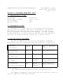
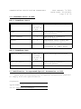
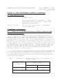
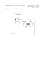
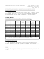
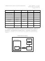
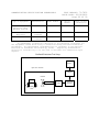
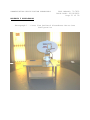
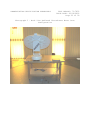
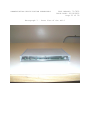
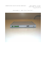
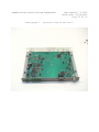
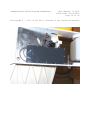
TEST REPORT FROM:
COMMUNICATION CERTIFICATION LABORATORY
TEST OF: LCU-1 & UCU-1
To EN 55022: 1998
FCC Part 15, Subpart B
ICES-003
Test Report Serial No: 73-7852
TEST REPORT FROM:
COMMUNICATION CERTIFICATION LABORATORY
1940 W. Alexander Street
Salt Lake City, Utah
84119-2039
Type of Report: Declaration of Conformity
TEST OF: LCU-1 & UCU-1
To EN 55022: 1998
FCC Part 15, Subpart B
ICES-003
Test Report Serial No: 73-7852
Applicant:
MotoSat
2343 South 2300 West
Salt Lake City, UT 84119
Date of Test: February 19, 2003
Issue Date: February 19, 2003
Equipment Receipt Date: February 19, 2003
COMMUNICATION CERTIFICATION LABORATORY
TEST REPORT: 73-7852
ISSUE DATE: 02/19/2003
Page 2 of 30
CERTIFICATION OF ENGINEERING REPORT
This report has been prepared by Communication Certification
Laboratory to document compliance of the device described below
with the Class B requirements of EN 55022: 1998, Federal
Communications Commission (FCC) Part 15, Subpart B and Industry
Canada (IC) ICES-003. This report may be reproduced in full,
partial reproduction may only be made with the written consent of
the laboratory. The results in this report apply only to the
sample tested.
-
Applicant:
MotoSat
-
Manufacturer:
MotoSat
-
Brand Name:
DataStorm
-
Model Number:
LCU-1 & UCU-1
On this 19th day of February 2003, I, individually, and for
Communication Certification Laboratory, certify that the
statements made in this engineering report are true, complete,
and correct to the best of my knowledge, and are made in good
faith.
Although NVLAP has recognized that the Communication
Certification Laboratory EMC testing facilities are in good
standing, NVLAP does not endorse the product described in this
report.
COMMUNICATION CERTIFICATION LABORATORY
Checked by: Kirk Thomas
V.P. Engineering
Tested by: Norman P. Hansen
EMC Technician
COMMUNICATION CERTIFICATION LABORATORY
TEST REPORT: 73-7852
ISSUE DATE: 02/19/2003
Page 3 of 30
TABLE OF CONTENTS
PAGE
SECTION 1.0
CLIENT INFORMATION.................................4
SECTION 2.0 EQUIPMENT UNDER TEST (EUT)..........................5
SECTION 3.0
TEST SPECIFICATION, METHODS & PROCEDURES...........7
SECTION 4.0
OPERATION OF EUT DURING TESTING...................11
SECTION 5.0
SUMMARY OF TEST RESULTS...........................13
SECTION 6.0 MEASUREMENTS, EXAMINATIONS AND DERIVED RESULTS.....14
APPENDIX 1 TEST PROCEDURES AND TEST EQUIPMENT..................17
APPENDIX 2 PHOTOGRAPHS.........................................21
APPENDIX 3 FCC Part 15/ICES-003 CONDUCTED DISTURBANCE DATA.....27
APPENDIX 4 FCC Part 15/ICES-003 COMPLIANCE INFORMATION.........28
COMMUNICATION CERTIFICATION LABORATORY
TEST REPORT: 73-7852
ISSUE DATE: 02/19/2003
Page 4 of 30
SECTION 1.0 CLIENT INFORMATION
1.1 Applicant:
Company Name:
MotoSat
2343 South 2300 West
Salt Lake City, UT 84119
Contact Name:
Title:
Edward C. Travis
Engineering Manager
1.2 Manufacturer:
Company Name:
MotoSat
2343 South 2300 West
Salt Lake City, UT 84119
Contact Name:
Title:
Edward C. Travis
Engineering Manager
1.3 Party Responsible for Declaration of Conformity:
Company Name:
MotoSat
2343 South 2300 West
Salt Lake City, UT 84119
Contact Name:
Title:
Edward C. Travis
Engineering Manager
Signature:
COMMUNICATION CERTIFICATION LABORATORY
TEST REPORT: 73-7852
ISSUE DATE: 02/19/2003
Page 5 of 30
SECTION 2.0 EQUIPMENT UNDER TEST (EUT)
2.1 Identification of EUT:
Brand Name:
Model Name or Number:
Serial Number:
Options Fitted:
DataStorm
LCU-1 & UCU-1
None
N/A
2.2 Description of EUT:
The LCU-1 is a controller for positioning and monitoring a
mobile satellite antenna. The UCU-1 is mounted to the mobile
satellite antenna and provides interfacing to the sensors and
positioning motors for the satellite antenna. 12 VDC, typically
a vehicle battery, is used to power both the LCU-1 and the UCU-1
and there is no provision for connection to any AC mains.
2.3 EUT and Support Equipment:
The FCC ID numbers for all the EUT and support equipment
used during the test (including inserted cards) are listed below:
Brand Name
Model Number
BN: DataStorm
FCC ID
Number
Description
Name of Interface
Ports / Interface
Cables
N/A
Controller
See Section 2.4
N/A
Controller
See Section 2.4
DoC
Laptop
Computer
N/A
Mobile
Satellite
Antenna
Serial/Unshielded
cable w/DB9 & DB15
connectors (2)
Motor Control/
Unshielded cable
(2)
MN: LCU-1 (1)
BN: DataStorm
MN: UCU-1 (1)
BN: HP Pavilion
MN: N5420
BN: DataStorm
MN: Satellite Antenna
Note: (1) EUT.
(2) Interface port connected to EUT (See Section 2.4)
The support equipment listed above was not modified in order to
achieve compliance with this standard.
COMMUNICATION CERTIFICATION LABORATORY
TEST REPORT: 73-7852
ISSUE DATE: 02/19/2003
Page 6 of 30
2.4 Interface Ports on EUT:
LCU-1 Interface Ports
Name of Ports
No. of
Ports
Fitted to
EUT.
Power
1
Motor Control
1
Serial
1
Signal
1
Cable Descriptions/Length
Unshielded 2 conductor
cable/5 meters
Unshielded 9 conductor
cable/10 meters
Unshielded cable w/DB9 and
DB15 connectos/3 meters
RG6 coax w/F-type connectors
terminated in 75Ω/1 meter
UCU-1 Interface Port
Name of Port
No. of
Ports
Fitted to
EUT.
Cable Descriptions/Length
Data (To LCU-1)
1
Motor Control
1
Unshielded 9 conductor
cable/10 meters
Unshielded cable/<1 meter
2.5 Modification Incorporated/Special Accessories on EUT:
There were no modifications or special accessories required
to comply with the specification.
Signature:
Typed Name: Edward C. Travis
Title: Engineering Manager
COMMUNICATION CERTIFICATION LABORATORY
TEST REPORT: 73-7852
ISSUE DATE: 02/19/2003
Page 7 of 30
SECTION 3.0 TEST SPECIFICATION, METHODS & PROCEDURES
3.1 Test Specification:
Title:
EN 55022: 1998
Information technology equipment – Radio
disturbance characteristics – Limits and
methods of measurement.
Purpose of Test:
The tests were performed to demonstrate
initial compliance.
3.2 Methods & Procedures:
3.2.1 Limits for Conducted Disturbance at Mains Terminals and
Telecommunication Ports
The equipment under test (EUT) shall meet the limits in
Tables 1 and 3 or 2 and 4, as applicable, including the average
limit and the quasi-peak limit when using, respectively, an
average detector receiver and a quasi-peak detector receiver and
measured in accordance with the methods described in Clause 9.
Either the voltage limits or the current limits in table 3 or 4,
as applicable, shall be met except for the measurement method of
C.1.3 where both limits shall be met. If the average limit is
met when using a quasi-peak detector receiver, the EUT shall be
deemed to meet both limits and measurement with the average
detector receiver is unnecessary.
If the reading on the measuring receiver shows fluctuations
close to the limit the reading shall be observed for at least 15
s at each measurement frequency; the highest reading shall be
recorded with the exception of any brief isolated high reading
which shall be ignored.
Table 1 - Limits for conducted disturbance at mains ports of
Class A ITE.
Frequency range
(MHz)
0.15 to 0.50
0.50 to 30
Limits (dBµV)
Quasi-peak
Average
79
73
66
60
NOTE – The lower limit shall apply at the transition
frequency
COMMUNICATION CERTIFICATION LABORATORY
TEST REPORT: 73-7852
ISSUE DATE: 02/19/2003
Page 8 of 30
Table 2 - Limits for conducted disturbance at mains ports of
Class B ITE.
Frequency range
(MHz)
0.15 to 0.50
0.50 to 5
5 to 30
Limits (dBµV)
Quasi-peak
Average
66 to 56
56
60
56 to 46
46
50
NOTE 1 – The lower limit shall apply at the transition
frequencies.
NOTE 2 – The limit decreases linearly with the logarithm of
the frequency in the range 0.15 MHz to 0.50 MHz.
Table 3 - Limits of conducted common mode (asymmetric mode)
disturbance at telecommunication ports in the frequency range
0.15 MHz to 30 MHz for Class A equipment.
Frequency range
(MHz)
0.15 to 0.5
0.5 to 30
Voltage Limits (dBµV)
Quasi-peak
Average
97 to 87
84 to 74
87
74
Current Limits (dBµA)
Quasi-peak
Average
53 to 43
40 to 30
43
30
NOTE 1 – The limit decreases linearly with the logarithm of the frequency in
the range 0.15 MHz to 0.50 MHz.
NOTE 2 – The current and voltage disturbance limits are derived for use with
an impedance stabilization network (ISN) which presents a common mode
(asymmetric mode) impedance of 150 Ω to the telecommunication port under test
(conversion factor is 20 log10 150/I = 44 dB).
COMMUNICATION CERTIFICATION LABORATORY
TEST REPORT: 73-7852
ISSUE DATE: 02/19/2003
Page 9 of 30
Table 4 - Limits of conducted common mode (asymmetric mode)
disturbance at telecommunication ports in the frequency range
0.15 MHz to 30 MHz for Class B equipment.
Frequency range
(MHz)
0.15 to 0.5
0.5 to 30
Voltage Limits (dBµV)
Quasi-peak
Average
84 to 74
74 to 64
74
64
Current Limits (dBµA)
Quasi-peak
Average
40 to 30
30 to 20
30
20
NOTE 1 – The limit decreases linearly with the logarithm of the frequency in
the range 0.15 MHz to 0.50 MHz.
NOTE 2 – The current and voltage disturbance limits are derived for use with
an impedance stabilization network (ISN) which presents a common mode
(asymmetric mode) impedance of 150 Ω to the telecommunication port under test
(conversion factor is 20 log10 150/I = 44 dB).
NOTE 3 – Provisionally, a relaxation of 10 dB over the frequency range of 6
MHz to 30 MHz is allowed for high-speed services having significant spectral
density in this band. However, this relaxation is restricted to the common
mode disturbance converted by the cable from the wanted signal. The
provisional relaxation of 10 dB will be reviewed no later than three years
after the date of withdrawal based on the results and interference cases seen
in this period. Whenever possible it is recommended to comply with the
limits without the provisional relaxation.
3.2.2 Limits for Radiated Disturbance
The EUT shall meet the limits of Tables 5 or 6 when measured
at the measuring distance R in accordance with the methods
described in clause 10. If the reading on the measuring receiver
shows fluctuations close to the limit, the reading shall be
observed for at least 15 s at each measurement frequency; the
highest reading shall be recorded with the exception of any brief
isolated high reading, which shall be ignored.
Table 5 - Limits for radiated disturbance of Class A ITE at a
test distance of 10 m.
Frequency range (MHz)
Quasi-peak limits
(dBµV/m)
30 to 230
230 to 1000
40
47
NOTE 1 - The lower limit shall apply at the transition frequency.
NOTE 2 – Additional provisions may be required for cases where
interference occurs.
COMMUNICATION CERTIFICATION LABORATORY
TEST REPORT: 73-7852
ISSUE DATE: 02/19/2003
Page 10 of 30
Table 6 - Limits for radiated disturbance of Class B ITE at a
test distance of 10 m.
Frequency range (MHz)
Quasi-peak limits
(dBµV/m)
30 to 230
230 to 1000
30
37
NOTE 1 - The lower limit shall apply at the transition frequency.
NOTE 2 – Additional provisions may be required for cases where
interference occurs.
3.2.3 Test Procedure
The conducted disturbance at mains and telecommunications
ports and radiated disturbance testing was performed according to
the procedures in EN 55022: 1998, Sections 8 through 10. Testing
was performed at CCL’s Wanship open area test site #2, located at
550 West Wanship Road, Wanship, UT. This site has been fully
described in a report submitted to the FCC, and was accepted in a
letter dated October 23, 2000 (90504).
CCL is accredited by National Voluntary Laboratory
Accreditation Program (NVLAP); NVLAP Lab Code:100272-0, which is
effective until September 30, 2003.
For radiated disturbance testing that is performed at
distances closer than the specified distance; an inverse
proportionality factor of 20 dB per decade is used to normalize
the measured data for determining compliance.
COMMUNICATION CERTIFICATION LABORATORY
TEST REPORT: 73-7852
ISSUE DATE: 02/19/2003
Page 11 of 30
SECTION 4.0 OPERATION OF EUT DURING TESTING
4.1 Operating Environment:
Power Supply:
12 VDC
4.2 Operating Modes:
Each mode of operation was exercised to produce worst-case
emissions. The worst-case emissions were with the LCU-1 & UCU-1
running in the following mode. The UCU-1 was mounted on the
DataStorm Satellite Antenna and connected to the positioning
motors and sensors. The LCU-1 was connected to the UCU-1 and the
laptop computer. The buses were active passing positioning data
between the laptop, LCU-1, and UCU-1.
4.3 EUT Exercise Software:
MotoSat software was used to exercise the EUT.
4.4 Configuration & Peripherals:
The LCU-1 & UCU-1 was placed on the table and connected to
the support equipment listed in Section 2.3 via each port listed
in Section 2.4. Shown in Section 4.5 is a block diagram of the
test configuration.
COMMUNICATION CERTIFICATION LABORATORY
TEST REPORT: 73-7852
ISSUE DATE: 02/19/2003
Page 12 of 30
4.5 Block Diagram of Test Configuration:
To Laptop Computer
and 12VDC Source
LCU-1
UCU-1
Satellite
Antenna
EUT Table
COMMUNICATION CERTIFICATION LABORATORY
TEST REPORT: 73-7852
ISSUE DATE: 02/19/2003
Page 13 of 30
SECTION 5.0 SUMMARY OF TEST RESULTS
5.1 Tables 2, 4 and 6 (Class B) of EN 55022: 1998
5.1.1 Summary of Tests:
Port
Frequency
Range
(MHz)
Result
Conducted Disturbance
(Hot Lead to Ground)
0.15 to 30
Not
Applicable
Conducted Disturbance
(Neutral Lead to Ground)
0.15 to 30
Telecommunication
Port
Conducted Common Mode
(asymmetric mode)
Disturbance
0.15 to 30
Enclosure
Radiated Disturbance
(Vertical Polarity)
30 to 1000
Complied
Enclosure
Radiated Disturbance
(Horizontal Polarity)
30 to 1000
Complied
AC Power
AC Power
Environmental Phenomena
(Note 1)
Not
Applicable
(Note 1)
Not
Applicable
(Note 2)
Note 1: There is no provision for operating the EUT from AC mains power;
therefore, this test is not applicable.
Note 2: There are no telecommunication ports on the EUT; therefore, this test is
not applicable.
5.2 Result
In the configuration tested, the EUT complied with the
requirements of the specification.
COMMUNICATION CERTIFICATION LABORATORY
TEST REPORT: 73-7852
ISSUE DATE: 02/19/2003
Page 14 of 30
SECTION 6.0 MEASUREMENTS, EXAMINATIONS AND DERIVED RESULTS
6.1 General Comments:
This section contains the test results only. Details of the
test methods used and a list of the test equipment used during
the measurements can be found in Appendix 1 of this report.
6.2 Test Results:
6.2.1 Radiated Disturbance Data (Vertical Polarity)
Frequency
(MHz)
Detector
Receiver
Reading
(dBµV)
Correction
Factor
(dB/m)
Field
Strength
(dBµV/m)
Class B
10 m
Limit
(dBµV/m)
Margin
(dB)
60.4
Peak (Note 1)
12.9
7.8
20.7
30.0
-9.3
72.3
Peak (Note 1)
14.6
7.3
21.9
30.0
-8.1
138.0
Peak (Note 1)
15.3
8.3
23.6
30.0
-6.4
208.8
Peak (Note 1)
9.4
11.6
21.0
30.0
-9.0
228.8
Peak (Note 1)
11.2
12.9
24.1
30.0
-5.9
256.0
Peak (Note 1)
18.0
13.8
31.8
37.0
-5.2
259.2
Peak (Note 1)
14.4
13.9
28.3
37.0
-8.7
422.4
Peak (Note 1)
12.0
19.0
31.0
37.0
-6.0
435.2
Peak (Note 1)
10.6
19.2
29.8
37.0
-7.2
Note 1: The reference detector used for the measurements was peak or quasipeak and the data was compared to the quasi-peak limit.
Measurement Uncertainty
The measurement uncertainty (with a 95% confidence level)
for this test was: ± 4.3 dB (30 MHz to 200 MHz) and ± 6.0 dB @ 3
meters ± 2.7 dB @ 10 meters (200 MHz to 1 GHz).
RESULT
The EUT complied with the specification limit by a margin of
5.2 dB.
COMMUNICATION CERTIFICATION LABORATORY
TEST REPORT: 73-7852
ISSUE DATE: 02/19/2003
Page 15 of 30
6.2.2 Radiated Disturbance Data (Horizontal Polarity)
Frequency
(MHz)
Detector
Receiver
Reading
(dBµV)
Correction
Factor
(dB/m)
Field
Strength
(dBµV/m)
Class B
10 m
Limit
(dBµV/m)
Margin
(dB)
137.8
Peak (Note 1)
13.9
8.3
22.2
30.0
-7.8
256.0
Peak (Note 1)
16.3
13.8
30.1
37.0
-6.9
360.0
Peak (Note 1)
12.5
18.1
30.6
37.0
-6.4
372.8
Peak (Note 1)
12.6
18.5
31.1
37.0
-5.9
385.6
Peak (Note 1)
14.6
18.7
33.3
37.0
-3.7
396.8
Peak (Note 1)
13.2
18.8
32.0
37.0
-5.0
411.2
Peak (Note 1)
13.7
18.9
32.6
37.0
-4.4
422.4
Peak (Note 1)
11.9
19.0
30.9
37.0
-6.1
435.2
Peak (Note 1)
13.8
19.2
33.0
37.0
-4.0
444.8
Peak (Note 1)
10.9
19.6
30.5
37.0
-6.5
Note 1: The reference detector used for the measurements was peak or quasipeak and the data was compared to the quasi-peak limit.
Measurement Uncertainty
The measurement uncertainty (with a 95% confidence level)
for this test was: ± 4.3 dB (30 MHz to 200 MHz) and ± 6.0 dB @ 3
meters ± 2.7 dB @ 10 meters (200 MHz to 1 GHz).
RESULT
The EUT complied with the specification limit by a margin of
3.7 dB.
COMMUNICATION CERTIFICATION LABORATORY
TEST REPORT: 73-7852
ISSUE DATE: 02/19/2003
Page 16 of 30
6.3 Sample Field Strength Calculation:
The field strength is calculated by adding the Correction
Factor (Antenna Factor + Cable Factor), to the measured level
from the receiver. The receiver amplitude reading is compensated
for any amplifier gain. The basic equation with a sample
calculation is shown below:
FS = RA + CF
Where
FS = Field Strength
RA = Receiver Amplitude Reading (Receiver Reading Amplifier Gain)
CF = Correction Factor (Antenna Factor + Cable Factor)
Assume a receiver reading of 42.5 dBµV is obtained from the
receiver, an amplifier gain of 26.5 dB and a correction factor of
8.5 dB/m. The field strength is calculated by subtracting the
amplifier gain and adding the correction factor, giving a field
strength of 24.5 dBµV/m, FS = (42.5 - 26.5) + 8.5 = 24.5 dBµV/m
COMMUNICATION CERTIFICATION LABORATORY
TEST REPORT: 73-7852
ISSUE DATE: 02/19/2003
Page 17 of 30
APPENDIX 1 TEST PROCEDURES AND TEST EQUIPMENT
Conducted Disturbance at Mains and Telecommunications Ports:
The conducted disturbance at mains and telecommunications
ports from the ITE was measured using a spectrum analyzer with a
quasi-peak adapter for peak, quasi-peak and average readings.
The quasi-peak adapter uses a bandwidth of 9 kHz, with the
spectrum analyzer's resolution bandwidth set at 100 kHz, for
readings in the 150 kHz to 30 MHz frequency ranges.
The conducted disturbance at mains and telecommunications
ports measurements are performed in a screen room using a (50
Ω/50 µH) Line Impedance Stabilization Network (LISN).
Where mains flexible power cords are longer than 1 m, the
excess cable is folded back and forth as far as possible so as to
form a bundle not exceeding 0.4 m in length.
Where the EUT is a collection of ITE with each ITE having
its own power cord, the point of connection for the LISN is
determined from the following rules:
a) Each power cord, which is terminated in a mains supply plug,
shall be tested separately.
b) Power cords, which are not specified by the manufacturer to
be connected via a host unit, shall be tested separately.
c) Power cords which are specified by the manufacturer to be
connected via a host unit or other power supplying equipment
shall be connected to that host unit and the power cords of
that host unit connected to the LISN and tested.
d) Where a special connection is specified, the necessary
hardware to effect the connection is supplied by the
manufacturer for the testing purpose.
e) When testing equipment with multiple mains cords, those cords
not under test are connected to an artificial mains network
(AMN) different than the AMN used for the mains cord under
test.
For AC mains port testing the desktop ITE are placed on a
non-conducting table at least 0.8 meters from the metallic floor,
and for telecommunications port testing the desktop ITE are
placed on a non-conducting table at least 0.4 meters from the
metallic floor. The equipment is placed a minimum of 40 cm from
all walls. Floor standing equipment is placed directly on the
earth grounded floor.
COMMUNICATION CERTIFICATION LABORATORY
TEST REPORT: 73-7852
ISSUE DATE: 02/19/2003
Page 18 of 30
Type of Equipment
Manufacturer
Model Number
Serial
Number
Date of Last
Calibration
Wanship Open Area
Test Site #2
CCL
N/A
N/A
12/31/2002
Test Software
CCL
Conducted
Emissions
Revision 1.2
N/A
Spectrum Analyzer
Hewlett
Packard
8566B
2230A01711
10/01/2002
Quasi-Peak
Detector
Hewlett
Packard
8565A
3107A01582
10/02/2002
LISN
EMCO
3825/2
9305-2099
01/27/2003
Conductance Cable
Wanship Site #2
CCL
Cable J
N/A
12/31/2002
Transient Limiter
Hewlett
Packard
11947A
3107A02266
12/31/2002
An independent calibration laboratory or CCL personnel calibrates all
the equipment listed above every 12 months following outlined calibration
procedures. All measurement instrumentation is traceable to the National
Institute of Standards and Technology (NIST). Supporting documentation
relative to tractability is on file and is available for examination upon
request.
Conducted Emissions Test Setup
Printer
Screened Room
Computer
LISN
Transient
Limiter
Spectrum
Analyzer
COMMUNICATION CERTIFICATION LABORATORY
TEST REPORT: 73-7852
ISSUE DATE: 02/19/2003
Page 19 of 30
Radiated Disturbance:
The radiated disturbance from the ITE was measured using a
spectrum analyzer with a quasi-peak adapter for peak and
quasi-peak readings. A preamplifier with a fixed gain of 26 dB
and a power amplifier with a fixed gain of 22 dB were used to
increase the sensitivity of the measuring instrumentation. The
quasi-peak adapter uses a bandwidth of 120 kHz, with the spectrum
analyzer's resolution bandwidth set at 1 MHz, for readings in the
30 to 1000 MHz frequency ranges.
A biconilog antenna was used to measure the frequency range
of 30 to 1000 MHz, at a distance of 10 meters from the EUT. The
readings obtained by these antennas are correlated to the levels
obtained with a tuned dipole antenna by adding antenna factors.
The configuration of the ITE was varied to find the maximum
radiated emission. The EUT was connected to the peripherals
listed in Section 2.4 via the interconnecting cables listed in
Section 2.5. A technician manually manipulated these
interconnecting cables to obtain worst-case radiated disturbance.
The ITE was rotated 360 degrees, and the antenna height was
varied from 1 to 4 meters to find the maximum radiated emission.
Where there was multiple interface ports all of the same type,
cables are either placed on all of the ports or cables added to
these ports until the emissions do not increase by more than 2
dB.
Desktop ITE is measured on a non-conducting table 0.8 meters
above the ground plane. The table is placed on a turntable,
which is level with the ground plane. For equipment normally
placed on floors, the equipment shall be placed directly on the
turntable.
Type of Equipment
Manufacturer
Model Number
Serial
Number
Date of Last
Calibration
Wanship Open Area
Test Site #2
CCL
N/A
N/A
12/31/2002
Test Software
CCL
Radiated
Emissions
Revision 1.3
N/A
Spectrum Analyzer
Hewlett
Packard
8566B
2230A01711
10/01/2002
Quasi-Peak
Detector
Hewlett
Packard
8565A
3107A01582
10/02/2002
Biconilog Antenna
EMCO
3142
9601-1009
12/30/2002
COMMUNICATION CERTIFICATION LABORATORY
TEST REPORT: 73-7852
ISSUE DATE: 02/19/2003
Page 20 of 30
Type of Equipment
Manufacturer
Model Number
Serial
Number
Date of Last
Calibration
10 Meter Radiated
Emissions Cable
Wanship Site #2
CCL
Cable L
N/A
12/31/2002
Pre/PowerAmplifier
Hewlett
Packard
8447F
3113A05161
09/19/2002
6 dB Attenuator
Hewlett
Packard
8491A
32835
12/31/2002
An independent calibration laboratory or CCL personnel calibrates all
the equipment listed above every 12 months following outlined calibration
procedures. All measurement instrumentation is traceable to the National
Institute of Standards and Technology (NIST). Supporting documentation
relative to tractability is on file and is available for examination upon
request.
Radiated Emissions Test Setup
Printer
Open Area Test Site
Computer
Antenna
EUT
6dB Attenuator
Turntable
Pre/Power
Amp
Spectrum
Analyzer
COMMUNICATION CERTIFICATION LABORATORY
TEST REPORT: 73-7852
ISSUE DATE: 02/19/2003
Page 21 of 30
APPENDIX 2 PHOTOGRAPHS
Photograph 1 – Front View Radiated Disturbance Worst Case
Configuration
COMMUNICATION CERTIFICATION LABORATORY
TEST REPORT: 73-7852
ISSUE DATE: 02/19/2003
Page 22 of 30
Photograph 2 – Back View Radiated Disturbance Worst Case
Configuration
COMMUNICATION CERTIFICATION LABORATORY
TEST REPORT: 73-7852
ISSUE DATE: 02/19/2003
Page 23 of 30
Photograph 3 – Front View of the LCU-1
COMMUNICATION CERTIFICATION LABORATORY
TEST REPORT: 73-7852
ISSUE DATE: 02/19/2003
Page 24 of 30
Photograph 4 – Back View of the LCU-1
COMMUNICATION CERTIFICATION LABORATORY
TEST REPORT: 73-7852
ISSUE DATE: 02/19/2003
Page 25 of 30
Photograph 5 – Internal View of the LCU-1
COMMUNICATION CERTIFICATION LABORATORY
TEST REPORT: 73-7852
ISSUE DATE: 02/19/2003
Page 26 of 30
Photograph 6 – View of the UCU-1 mounted to the DataStorm Antenna
COMMUNICATION CERTIFICATION LABORATORY
TEST REPORT: 73-7852
ISSUE DATE: 02/19/2003
Page 27 of 30
APPENDIX 3 FCC Part 15/ICES-003 CONDUCTED DISTURBANCE AT MAINS
PORTS DATA
There is no provision for operating the EUT from AC mains
power; therefore, these tests are not applicable.
COMMUNICATION CERTIFICATION LABORATORY
TEST REPORT: 73-7852
ISSUE DATE: 02/19/2003
Page 28 of 30
APPENDIX 4 FCC Part 15/ICES-003 COMPLIANCE INFORMATION
A.4.1 LABEL AND COMPLIANCE STATEMENT
The label of the MotoSat DataStorm LCU-1 & UCU-1 were not
available at the time of this report. Below are the FCC labeling
requirements:
Section 15.17(a)
(3) All other devices shall bear the following statement in
a conspicuous location on the device:
This device complies with Part 15 of the FCC
Rules. Operation is subject to the following two
conditions: (1) this device may not cause harmful
interference, and (2) this device must accept any
interference received, including interference that may
cause undesired operation.
(4) Where a device is constructed in two or more sections
connected by wires and marketed together, the statement specified
under paragraph (a) of this section is required to be affixed
only to the main control unit.
Section 15.17(b)
(4) The label shall not be a stick-on, paper label. The
label on these products shall be permanently affixed to the
product and shall be readily visible to the purchaser at the time
of purchase, as described in Section 2.925(d) of this chapter.
"Permanently affixed" means that the label is etched, engraved,
stamped, silkscreened, indelibly printed, or otherwise
permanently marked on a permanently attached part of the
equipment or on a nameplate of metal, plastic, or other material
fastened to the equipment by welding, riveting, or a permanent
adhesive. The label must be designed to last the expected
lifetime of the equipment in the environment in which the
equipment may be operated and must not be readily detachable.
COMMUNICATION CERTIFICATION LABORATORY
TEST REPORT: 73-7852
ISSUE DATE: 02/19/2003
Page 29 of 30
A.4.2 BLOCK DIAGRAM
A block diagram showing the clock frequencies and signal
paths of the MotoSat DataStorm LCU-1 & UCU-1 were not available
at the time of this report.
COMMUNICATION CERTIFICATION LABORATORY
TEST REPORT: 73-7852
ISSUE DATE: 02/19/2003
Page 30 of 30
A.4.3 USER’S MANUAL
A copy of the User’s manual containing the FCC warning
statement was not available at the time of this report.
Sample of Class B Warning Statement
NOTE: This equipment has been tested and found to comply with
the limits for a Class B digital device pursuant to part 15 of
the FCC Rules. These limits are designed to provide reasonable
protection against harmful interference in a residential
installation. This equipment generates, uses and can radiated
radio frequency energy and, if not installed and used in
accordance with the instructions, may cause harmful interference
to radio communications. However, there is no guarantee that
interference will not occur in a particular installation. If
this equipment does cause harmful interference to radio or
television reception, which can be determined by turning the
equipment off and on, the user is encouraged to try to correct
the interference by one or more of the following measures:
-
Reorient or relocate the receiving antenna.
-
Increase the separation between the equipment and receiver.
-
Connect the equipment into an outlet on a circuit different
from that to which the receiver is connected.
Consult the dealer or an experienced radio/TV technician for
help.


![TECNARE DPA 28X OWNER [Ingles]](http://vs1.manualzilla.com/store/data/005945802_1-b9e6af5d2577bc9a733b6f858960f622-150x150.png)