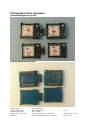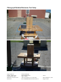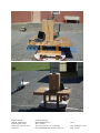
1
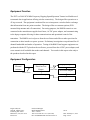
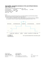
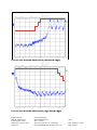
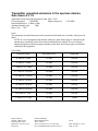
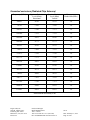
ROGERS LABS, INC.
th
4405 West 259 Terrace
Louisburg, KS 66053
Phone / Fax (913) 837-3214
ENGINEERING TEST REPORT FORM
For
TESTING to EN 300 328 v1.8.1 (2012-06)
For
Laird Technologies
11160 Thompson Avenue
Lenexa KS 66219
913 981-5712
Daniel Waters
Engineering Specialist
Model: RM024 Series
Digital Transmission System Transmitter
Frequency 2,400-2,483.5 MHz
Test Date: October 10, 2014
Test Report Number: 141007
Certification Date: October 10, 2014
Certifying Engineer:
Scot D. Rogers
Rogers Labs, Inc.
4405 West 259th Terrace
Louisburg, KS 66053
Telephone/Facsimile: (913) 837-3214
This report shall not be reproduced except in full, without the written approval of the laboratory.
This report must not be used by the client to claim product certification, approval, or
endorsement by NVLAP, NIST, or any agency of the Federal Government.
File: Laird RM024 EN 300 328 141007 r2
Page 1 of 29
Table of Contents
TABLE OF CONTENTS.................................................................................................. 2
REVISIONS..................................................................................................................... 3
OPINION / INTERPRETATION OF RESULTS ............................................................... 4
EQUIPMENT TESTED .................................................................................................... 4
Equipment Function ...........................................................................................................................................5
Equipment Configuration ..................................................................................................................................5
APPLICANT DETAILS ................................................................................................... 6
ENVIRONMENTAL CONDITIONS................................................................................ 12
UNITS OF MEASUREMENTS ...................................................................................... 12
TEST SITE LOCATIONS .............................................................................................. 12
RF OUTPUT POWER, SUB CLAUSE 4.3.1.1 .............................................................. 13
DUTY CYCLE, TX-SEQUENCE, TX-GAP, SUB CLAUSE 4.3.1.2 ............................... 13
ACCUMULATED TRANSMIT TIME, FREQUENCY OCCUPATION AND HOPPING
SEQUENCE, SUB CLAUSE 4.3.1.3 ............................................................................. 14
Plot of Dwell time on channel ........................................................................................................................... 15
Plot of channel occupancy during 30-second period ...................................................................................... 15
HOPPING FREQUENCY SEPARATION, SUB CLAUSE 4.3.1.4 ................................. 16
Plot of Frequency Serration ............................................................................................................................. 16
MEDIUM UTILIZATION (MU) FACTOR, SUB CLAUSE 4.3.1.5 .................................. 17
ADAPTIVITY (ADAPTIVE FREQUENCY HOPPING), SUB CLAUSE 4.3.1.6 ............. 17
OCCUPIED CHANNEL BANDWIDTH, SUB CLAUSE 4.3.1.7 ..................................... 18
Plot of Occupied Bandwidth ............................................................................................................................ 18
Rogers Labs, Inc.
4405 W. 259th Terrace
Louisburg, KS 66053
Phone/Fax: (913) 837-3214
Revision 2
Laird Technologies
Model: RM024 Series
Test #: 141007
Test to: EN 300 328 v1.8.1 (2012-06)
File: Laird RM024 EN 300 328 141007 r2
SN: A
Date: February 13, 2015
Page 2 of 29
TRANSMITTER UNWANTED EMISSIONS IN THE OUT-OF-BAND DOMAIN, SUB
CLAUSE 4.3.1.8 ........................................................................................................... 19
Plot of Out-of-band emissions (low band edge) .............................................................................................. 20
Plot of Out-of-band emissions (high band edge) ............................................................................................. 20
TRANSMITTER UNWANTED EMISSIONS IN THE SPURIOUS DOMAIN, SUB
CLAUSE 4.3.1.9 ........................................................................................................... 21
Unwanted emissions (Antenna Port Conducted) ............................................................................................ 22
Unwanted emissions (Radiated Chip Antenna) .............................................................................................. 23
Unwanted emissions (Radiated 2 dBi Dipole Antenna) ................................................................................. 24
RECEIVER SPURIOUS EMISSIONS, SUB CLAUSE 4.3.1.10 .................................... 25
RECEIVER BLOCKING, SUB CLAUSE 4.3.1.11 ......................................................... 25
TEST EQUIPMENT AND ANCILLARIES USED FOR TESTS ..................................... 26
PHOTOGRAPHS OF THE EQUIPMENT ...................................................................... 27
External photograph front side ........................................................................................................................ 27
External photograph rear side ......................................................................................................................... 27
Photograph Radiated Emissions Test Setup ................................................................................................... 28
Revisions
Revision 2 Issued February 13, 2015 – updated Opinion table ref (pg4), added model info (pg6)
Revision 1 Issued October 29, 2014
Rogers Labs, Inc.
4405 W. 259th Terrace
Louisburg, KS 66053
Phone/Fax: (913) 837-3214
Revision 2
Laird Technologies
Model: RM024 Series
Test #: 141007
Test to: EN 300 328 v1.8.1 (2012-06)
File: Laird RM024 EN 300 328 141007 r2
SN: A
Date: February 13, 2015
Page 3 of 29
Opinion / Interpretation of Results
Tests Performed
Results
Maximum transmit power, EN 300 328 paragraph 5.3.2
Complies
Power Spectral Density, EN 300 328 paragraph 5.3.3
N/A
Duty Cycle, Tx-sequence, Tx-gap, EN 300 328 paragraph 5.3.2
N/A
Dwell time, Minimum Frequency Occupation & Hopping Sequence,
EN 300 328 paragraph 5.3.4
Complies
EN 300 328 paragraph 5.3.5 Frequency hopping requirements
Complies
Medium Utilization (MU) Factor, EN 300 328 paragraph 5.3.2
N/A
Adaptivity (modulations other than FHSS), EN 300 328 paragraph 5.3.7
N/A
Occupied Channel Bandwidth, EN 300 328 paragraph 5.3.8
Complies
Transmitter Out-of-Band Domain, EN 300 328 paragraph 5.3.9
Complies
Transmitter unwanted emissions spurious domain, EN 300 328 paragraph 5.3.10
Complies
Receiver spurious emissions, EN 300 328 paragraph 5.3.11
Complies
Receiver Blocking, EN 300 328 paragraph 5.3.7
N/A
Equipment Tested
Equipment
Model / PN
Serial Number
EUT
RM024
A
CPU
2 dBi Chip
5 dBi Dipole
HP CRVSA-02T1-75 TW24416178
WIC2450A
N/A
S151-6-PX-2450S
N/A
Test results in this report relate only to the items tested.
Rogers Labs, Inc.
4405 W. 259th Terrace
Louisburg, KS 66053
Phone/Fax: (913) 837-3214
Revision 2
Laird Technologies
Model: RM024 Series
Test #: 141007
Test to: EN 300 328 v1.8.1 (2012-06)
File: Laird RM024 EN 300 328 141007 r2
SN: A
Date: February 13, 2015
Page 4 of 29
Equipment Function
The EUT is a 2404-2470 MHz Frequency Hopping Spread Spectrum Transceiver Module used
to transmit data in applications offering wireless connectivity. The design offers operation as a
43 hop set mode. The equipment is marketed for use to incorporate a wireless link to exchange
data information from one point to another. The design offers two antenna options (PCB
mounted chip antenna and u.fl connection). For testing purposes, the RM024 transceiver was
connected to the manufacturer supplied test fixture, AC/DC power adapter, and communicating
to the laptop computer allowing for data communications and operational control of the
transmitter. The RM024 received power from the test fixture and offers no other provision for
connection to other interface or power systems. Preliminary investigation was performed for all
channel bandwidths and modes of operation. Testing of the RM024 and support equipment was
performed with the EUT placed on the test fixture, powered from the AC/DC power adapter, and
set to transmit in all available data modes and channels. Test results in this report relate only to
the products described in this report.
Equipment Configuration
Optional
External
Antenna
(EUT)
Placed on Test
Fixture
Laptop Computer
RS-232 Cable
Coaxial Cable
AC Power Adapter
AC Power Adapter
Utility Power
Rogers Labs, Inc.
4405 W. 259th Terrace
Louisburg, KS 66053
Phone/Fax: (913) 837-3214
Revision 2
Laird Technologies
Model: RM024 Series
Test #: 141007
Test to: EN 300 328 v1.8.1 (2012-06)
File: Laird RM024 EN 300 328 141007 r2
SN: A
Date: February 13, 2015
Page 5 of 29
Applicant Details
Applicant's details
X Manufacturer
Importer
Distributor
Agent
Category of applicant
(please tick relevant box opposite)
Company name
Street address
Postal code, city
Post box
Postal code, city
Country
Contact person name
Phone number
Fax number
Email address
Web site address
Company name
Street address
Postal code, city
Post box
Postal code, city
Country
Contact person name
Phone number
Fax number
Email address
Web site address
Laird
11160 Thompson Ave.
Lenexa, KS 66219
U.S.A
Daniel Waters
913-981-5712
913-492-1243
[email protected]
http://www.lairdtech.com/Products/Wireless-Module/
Manufacturer's details (1)
Laird
11160 Thompson Ave.
Lenexa, KS 66219
U.S.A
Daniel Waters
913-981-5712
913-492-1243
[email protected]
http://www.lairdtech.com/Products/Wireless-Module/
(1) skip this section if applicant is manufacturer.
Type designation
The type designation may be either a single alphanumeric code or an alphanumeric code divided into two parts (2)
Type designation as a single alphanumeric code
Type designation in two parts
1 Equipment series no (3)
RM024
2 Equipment specific no
RM024-S10-C-20 / RM024-S10-M-20 / RM024-P10-C-20
(4)
/ RM024-P10-M-20 / RM024-S10-C-24 / RM024-S10-M-24 /
RM024-P10-C-24 /RM024-P10-M-24
(2)
(3)
(4)
This is the manufacturer's numeric or alphanumeric code or name that is specific to a particular equipment. It may contain
information in coded form on the characteristics of the equipment e.g. frequency, power. The manufacturer is free to choose the form
of the type designation.
This is the number, code or trade name used by the manufacturer to describe a series or 'family' of equipment of substantially the same
mechanical and electrical construction which will include a number of related equipments. This number is often referred to as the
"model no.".
This is the manufacturer's identification number given to a specific equipment in the series or 'family' of equipments. It is often
referred to as the "identification number".
Rogers Labs, Inc.
4405 W. 259th Terrace
Louisburg, KS 66053
Phone/Fax: (913) 837-3214
Revision 2
Laird Technologies
Model: RM024 Series
Test #: 141007
Test to: EN 300 328 v1.8.1 (2012-06)
File: Laird RM024 EN 300 328 141007 r2
SN: A
Date: February 13, 2015
Page 6 of 29
Type of equipment (5)
Stand-alone (Equipment with or without its own control provisions)
Combined Equipment (Equipment where the radio part is fully integrated within another type of equipment)
X Plug-in card (Equipment intended for a variety of host systems)
Other:
(5) Equipment belongs to one of the following (and only to one). Separate application forms are required for each variant.
Type of antenna
integral antenna with temporary RF connector
X integral antenna without temporary RF connector
X antenna connector
Number of antenna assembly(ies) submitted
2
Antenna assembly parameters
Antenna assembly identification
Antenna assembly gain (dBi)
2.4Ghz Dipole / Part# S181FL-6-PX-2450S
2dBi
2.4Ghz Chip / Part# WIC2450-A
2dBi
Transmitter technical characteristics
Method of frequency generation
Crystal
(please tick relevant box opposite)
X Synthesizer
Other:
Transmitter operating frequency range in MHz 2402 MHz to 2470 MHz
Spread spectrum technique used
Direct sequence (DSSS)
X Frequency hopping (FHSS)
Combined
Other :
Spread spectrum parameters
chip sequence length (bits)
spectrum width (MHz)
FHSS total number of hops (units)
43
dwell time (milliseconds)
10.62 mS
bandwidth per hop (MHz)
1.137 MHz
max. separation of hops (MHz)
1.05 MHz
Transmitter aggregate data rate (bits per second (> 250 kbit/s))
500kbit/s or 280kbit/s
DSSS
(see ETSI EN 300 328, clause 5.1.2)
Rogers Labs, Inc.
4405 W. 259th Terrace
Louisburg, KS 66053
Phone/Fax: (913) 837-3214
Revision 2
Laird Technologies
Model: RM024 Series
Test #: 141007
Test to: EN 300 328 v1.8.1 (2012-06)
File: Laird RM024 EN 300 328 141007 r2
SN: A
Date: February 13, 2015
Page 7 of 29
Transmitter RF power characteristics
Antenna assembly identification
RF power
2.4Ghz Dipole
Effective radiated power (dBm)
Peak power density, FHSS (dBm/100kHz)
Peak power density, DSSS (mW/MHz)
< +10dBm
2.4Ghz Chip
< +10dBm
Effective radiated power (dBm)
Peak power density, FHSS (dBm/100kHz)
Peak power density, DSSS (mW/MHz)
Effective radiated power (dBm)
Peak power density, FHSS (dBm/100kHz)
Peak power density, DSSS (mW/MHz)
Effective radiated power (dBm)
Peak power density, FHSS (dBm/100kHz)
Peak power density, DSSS (mW/MHz)
Is transmitter output power
variable?
Can the transmitter operate
unmodulated ?
Is the transmitter intended for
Continuous duty ?
Is the transmitter intended for
Intermittent duty ?
Transmitter duty cycle
Is continuous operation possible
for testing purposes ?
Equipment state during the test
Effective radiated power (dBm)
Peak power density, FHSS (dBm/100kHz)
Peak power density, DSSS (mW/MHz)
No
X Yes
continuous variable
stepped variable
stepsize (dB)
minimum RF power (dBm)
X maximum RF power (dBm):
...+9dBm.........
X No
Yes
X No
Yes
No
X Yes
Tx on (seconds)
10mS
Tx off (seconds)
3mS
Duty cycle (Tx on / (Tx on + Tx off))
76%
X No
Yes
Tx on (seconds)
10mS
Tx off (seconds)
3mS
Duty cycle (Tx on / (Tx on + Tx off))
76%
If the transmitter ON time is less than 10 microseconds, the applicant shall appoint a test house and agree a test method with the
National Regulatory Authority and accreditation authority.
Rogers Labs, Inc.
4405 W. 259th Terrace
Louisburg, KS 66053
Phone/Fax: (913) 837-3214
Revision 2
Laird Technologies
Model: RM024 Series
Test #: 141007
Test to: EN 300 328 v1.8.1 (2012-06)
File: Laird RM024 EN 300 328 141007 r2
SN: A
Date: February 13, 2015
Page 8 of 29
Transmitter power source (6)
Battery
Nickel Cadmium
(please tick relevant box opposite)
Mercury
Alkaline
Lead acid (Vehicle regulated)
Leclanché
Lithium
Other
DC voltage (VDC)
2.3 – 3.6 Volts
DC maximum current (mA)
120mA (40ma average.)
End point voltage as quoted by equipment manufacturer
(Volt)
AC mains
AC Voltage (VAC)
AC mains frequency (Hz)
AC Phase
Single phase
Three phase
Common power source for transmitter and
X Yes
receiver
No
(6) If a transmitter and receiver use the same power source, this should be declared. In such cases only the box for the
transmitter power source should be filled in.
Receiver technical characteristics
Method of frequency generation
Crystal
(please tick relevant box opposite)
X Synthesizer
Other:
Intermediate frequencies
1st (MHz)
0.406MHz (500k data rate)
0.28MHz (280k data rate)
2nd (MHz)
3rd (MHz)
Is local oscillator injection frequency higher
Higher
or lower than the receiver nominal
X Lower Near zero IF
frequency ?
Receiver operating frequency range (MHz) 2404 to 2470 MHz
Receiver power source (7)
Battery
Nickel Cadmium
(please tick relevant box opposite)
Mercury
Alkaline
Lead acid (Vehicle regulated)
Leclanché
Lithium
Other
DC voltage (VDC)
2.3-3.6V
DC maximum current (mA)
33mA (12mA average)
Rogers Labs, Inc.
4405 W. 259th Terrace
Louisburg, KS 66053
Phone/Fax: (913) 837-3214
Revision 2
Laird Technologies
Model: RM024 Series
Test #: 141007
Test to: EN 300 328 v1.8.1 (2012-06)
File: Laird RM024 EN 300 328 141007 r2
SN: A
Date: February 13, 2015
Page 9 of 29
End point voltage as quoted by equipment manufacturer
(volt)
AC mains
AC Voltage (VAC)
AC mains frequency (Hz)
AC Phase
Single phase
Three phase
Common power source for transmitter and
Yes
receiver
No
(7) If a transmitter and receiver use the same power source, this should be declared. In such cases only the box for the
transmitter power source should be filled in.
Transmitter and receiver characteristics
ITU designation(s) of emission
1M02 F1D
Extreme temperature ranges over which equipment is to be type tested
-20°C to +55°C
-10°C to +55°C
-0°C to +35°C (indoor home and office use)
X Other (8) :
Extreme temperature ranges for the host(s) : -40°C to +85°C
(8) The equipment shall be tested over the following temperature ranges :
a) -20oC to +55oC in the case of stand-alone equipment ;
b) over the extremes of the temperature range(s) of the intended host equipment(s) in case of plug-in radio devices (see
ETSI EN 300 328 clause 6.4.1).
Construction of equipment
Single unit
X Multiple units
If multiple units describe each one clearly:
There is one top-level hardware version available in the RM024 family. That top-level surface
mount version can be ordered by itself or mounted to a pluggable interface board. Hardware also
includes the option for either an integral 2dBi chip antenna or a U.FL RF connector, which can be
used to connect dipoles up to 2 dBi in gain. The option also exists for removing the chip antenna
section of the board when it is not being populated.
*PART #
FORM FACTOR ANTENNA
U.FL
RM024-S10-C-20 Surface Mount
RM024-S10-M-20 Surface Mount U.FL or chip
U.FL
RM024-P10-C-20 Pluggable
RM024-P10-M-20 Pluggable U.FL or chip
Rogers Labs, Inc.
4405 W. 259th Terrace
Louisburg, KS 66053
Phone/Fax: (913) 837-3214
Revision 2
Laird Technologies
Model: RM024 Series
Test #: 141007
Test to: EN 300 328 v1.8.1 (2012-06)
File: Laird RM024 EN 300 328 141007 r2
SN: A
Date: February 13, 2015
Page 10 of 29
Automatic equipment switch off
If the equipment is designed to automatically switch off at a
applies
predetermined voltage level which is higher or lower in value than
does not apply
the battery minimum voltage calculated values this shall be clearly X cut off voltage ...1.8V
stated.
Other items supplied
Spare batteries
Battery charging device
Special tools for dismantling equipment
Host Systems (see ETSI EN 300 328, clauses 6.4 and 6.5) (supply host details separately)
X Test jig or interface box (if applicable)
RF test fixture
User Manual
Technical documentation (Handbook and circuit diagrams)
Test data sequence specified (must be supplied separately
other :............................
(9) The EN 300 328 indicates information to be provided in the User Manual. The User Manual shall be provided with the application form.
Declarations
Are the equipments submitted representative production models ?
If not are the equipments pre-production models?
If pre-production equipments are submitted will the final production
equipments be identical in all respects with the equipment tested ?
If no supply full details:
Details:
Is the equipment submitted marked in accordance with R&TTE
requirements.
X yes
no
yes
X no
yes
no
X yes
no
I hereby declare that I am entitled to sign on behalf of the applicant and that the
information supplied is correct and complete.
Signature
Name
Position held
Date
Daniel E. Waters
Certifications Specialist
28 October 2014
Rogers Labs, Inc.
4405 W. 259th Terrace
Louisburg, KS 66053
Phone/Fax: (913) 837-3214
Revision 2
Laird Technologies
Model: RM024 Series
Test #: 141007
Test to: EN 300 328 v1.8.1 (2012-06)
File: Laird RM024 EN 300 328 141007 r2
SN: A
Date: February 13, 2015
Page 11 of 29
Environmental Conditions
Ambient Temperature
23.7° C
Relative Humidity
42%
Atmospheric Pressure
1011.3 mb
Units of Measurements
Conducted EMI
Data is in dBµV; dB referenced to one microvolt
Radiated EMI
Data is in dBµV/m; dB/m referenced to one microvolt per meter
Test Site Locations
Conducted EMI
The AC power line conducted emissions testing performed in a shielded
screen room located at Rogers Labs, Inc., 4405 W. 259th Terrace,
Louisburg, KS
Radiated EMI
The radiated emissions tests were performed at the 3 meters, Open Area
Test Site (OATS) located at Rogers Labs, Inc., 4405 W. 259th Terrace,
Louisburg, KS
Site Approval
Refer to Annex for FCC and Industry Canada Site Registration Letters
NVLAP
Lab code 200087-0
Rogers Labs, Inc.
4405 W. 259th Terrace
Louisburg, KS 66053
Phone/Fax: (913) 837-3214
Revision 2
Laird Technologies
Model: RM024 Series
Test #: 141007
Test to: EN 300 328 v1.8.1 (2012-06)
File: Laird RM024 EN 300 328 141007 r2
SN: A
Date: February 13, 2015
Page 12 of 29
RF Output Power, Sub clause 4.3.1.1
Applicants declared operating frequency band: 2404 - 2470
Lowest frequency
2,404 MHz
Highest frequency
Rated Output Power 8 dBm (±1dB)
Antenna assembly gain
2 dBi
Duty Cycle 76%
Test Condition
2,470 MHz
Transmitter Power (dBm)
Lowest
Middle
Highest
Frequency
Frequency
Frequency
Tnom 21.1°C
Vnom 3.0 Vdc
8.98
9.00
8.97
Tmin -30.0°C
Vmin 2.3 Vdc
9.11
9.13
9.10
Tmin -30.0°C
Vmax 3.6 Vdc
9.11
9.13
9.10
Tmax 80.0°C
Vmin 2.3 Vdc
8.81
8.93
8.80
Tmax 80.0°C
Vmax 3.6 Vdc
8.81
8.93
8.80
Measurement Uncertainty
1.5 dB
Limits
Under all test conditions
20 dBm (less than -10 dBW)
Maximum transmit power measurement was performed as defined in EN 300 328- 4.3.2
Reference Number(s) of Test Equipment Used (for references see test equipment listing)
7, 8, 9
Duty Cycle, Tx-sequence, Tx-gap, Sub clause 4.3.1.2
These requirements do not apply for equipment with a maximum declared RF Output power of
less than 10 dBm e.i.r.p. or for equipment when operating in a mode where the RF Output power
is less than 10 dBm e.i.r.p.
Rogers Labs, Inc.
4405 W. 259th Terrace
Louisburg, KS 66053
Phone/Fax: (913) 837-3214
Revision 2
Laird Technologies
Model: RM024 Series
Test #: 141007
Test to: EN 300 328 v1.8.1 (2012-06)
File: Laird RM024 EN 300 328 141007 r2
SN: A
Date: February 13, 2015
Page 13 of 29
Accumulated Transmit Time, Frequency Occupation and
Hopping Sequence, Sub clause 4.3.1.3
Applicants declared operating frequency band: 2404 - 2470
Lowest frequency
2,404 MHz
Highest frequency
Rated Output Power 8 dBm (±1dB)
Antenna assembly gain
2 dBi
Duty Cycle 76%
2,470 MHz
The EUT utilizes 43 hopping channels and occupies each equally.
Dwell time of EUT was measured and plots produced demonstrating compliance.
Limits
Under all test conditions Maximum Dwell time
0.4 seconds
Reference Number(S) of Test Equipment Used (for references see test equipment listing)
1, 7, 8, 9
The device hops across 43 channels in the frequency band 2404 to 2466.9 MHz selecting channel
frequency from a pseudo-random list of hopping frequencies at a rate of 0.013 seconds (13mS)
hopping rate. The unit dwells on channel 10.625 mS, waits 2.375 mS every hop, and hops at a
rate of 13 mS to the next channel in the hop sequence. The design hops on channel 1 times in a
0.43-second period (10.625 mS*43 channels = 0.43 seconds). The number of times on channel
times the dwell time on channel predicts the accumulated transmit time is 10.625 mS.
The design uses each chop channel equally in the predefined hop list of 43 channels, which is
greater than the required 2 channels.
The design occupies the hop channel for the duration of the typical dwell time.
Rogers Labs, Inc.
4405 W. 259th Terrace
Louisburg, KS 66053
Phone/Fax: (913) 837-3214
Revision 2
Laird Technologies
Model: RM024 Series
Test #: 141007
Test to: EN 300 328 v1.8.1 (2012-06)
File: Laird RM024 EN 300 328 141007 r2
SN: A
Date: February 13, 2015
Page 14 of 29
Plot of Dwell time on channel
Plot of channel occupancy during 30-second period
Rogers Labs, Inc.
4405 W. 259th Terrace
Louisburg, KS 66053
Phone/Fax: (913) 837-3214
Revision 2
Laird Technologies
Model: RM024 Series
Test #: 141007
Test to: EN 300 328 v1.8.1 (2012-06)
File: Laird RM024 EN 300 328 141007 r2
SN: A
Date: February 13, 2015
Page 15 of 29
Hopping Frequency Separation, Sub clause 4.3.1.4
Applicants declared operating frequency band: 2404 - 2470
Lowest frequency
2,404 MHz
Highest frequency
Rated Output Power 8 dBm (±1dB)
Antenna assembly gain
2 dBi
Duty Cycle 76%
2,470 MHz
Limit
For equipment with a maximum declared RF Output power level of less than 10 dBm e.i.r.p. or
for non-adaptive Frequency Hopping equipment operating in a mode where the RF Output power
is less than 10 dBm e.i.r.p. only the minimum Hopping Frequency Separation of 100 kHz
applies.
Plot of Frequency Serration
Rogers Labs, Inc.
4405 W. 259th Terrace
Louisburg, KS 66053
Phone/Fax: (913) 837-3214
Revision 2
Laird Technologies
Model: RM024 Series
Test #: 141007
Test to: EN 300 328 v1.8.1 (2012-06)
File: Laird RM024 EN 300 328 141007 r2
SN: A
Date: February 13, 2015
Page 16 of 29
Medium Utilization (MU) Factor, Sub clause 4.3.1.5
This requirement does not apply for equipment with a maximum declared RF Output power level
of less than 10 dBm e.i.r.p. or for equipment when operating in a mode where the RF Output
power is less than 10 dBm e.i.r.p.
Adaptivity (Adaptive Frequency Hopping), Sub clause 4.3.1.6
This requirement does not apply to non-adaptive equipment or adaptive equipment operating in a
non-adaptive mode providing the equipment complies with the requirements and/or restrictions
applicable to non-adaptive equipment.
In addition, this requirement does not apply for equipment with a maximum declared RF Output
power level of less than 10 dBm e.i.r.p. or for equipment when operating in a mode where the RF
Output power is less than 10 dBm e.i.r.p.
Rogers Labs, Inc.
4405 W. 259th Terrace
Louisburg, KS 66053
Phone/Fax: (913) 837-3214
Revision 2
Laird Technologies
Model: RM024 Series
Test #: 141007
Test to: EN 300 328 v1.8.1 (2012-06)
File: Laird RM024 EN 300 328 141007 r2
SN: A
Date: February 13, 2015
Page 17 of 29
Occupied Channel Bandwidth, Sub clause 4.3.1.7
Applicants declared operating frequency band: 2404 - 2470
Lowest frequency
2,404 MHz
Highest frequency
Rated Output Power 8 dBm (±1dB)
Antenna assembly gain
2 dBi
Duty Cycle 76%
2,470 MHz
Limit
The Occupied Channel Bandwidth for each hopping frequency shall fall completely within the
band given in clause 1.
For non-adaptive Frequency Hopping equipment with e.i.r.p greater than 10 dBm, the Occupied
Channel Bandwidth for every occupied hopping frequency shall be equal to or less than the
Nominal Channel Bandwidth declared by the supplier. See clause 5.3.1 j). This declared value
shall not be greater than 5 MH.
Plot of Occupied Bandwidth
Rogers Labs, Inc.
4405 W. 259th Terrace
Louisburg, KS 66053
Phone/Fax: (913) 837-3214
Revision 2
Laird Technologies
Model: RM024 Series
Test #: 141007
Test to: EN 300 328 v1.8.1 (2012-06)
File: Laird RM024 EN 300 328 141007 r2
SN: A
Date: February 13, 2015
Page 18 of 29
Transmitter unwanted emissions in the out-of-band domain,
Sub clause 4.3.1.8
Applicants declared operating frequency band: 2404 - 2470
Lowest frequency
2,404 MHz
Highest frequency
Rated Output Power 8 dBm (±1dB)
Antenna assembly gain
2 dBi
Duty Cycle 76%
2,470 MHz
Limit
The transmitter unwanted emissions in the out-of-band domain but outside the allocated band,
shall not exceed the values provided by the mask in figure 1.
NOTE: Within the 2 400 MHz to 2 483,5 MHz band, the Out-of-band emissions are fulfilled
by compliance with the Occupied Channel Bandwidth requirement in clause 4.3.1.8.
Rogers Labs, Inc.
4405 W. 259th Terrace
Louisburg, KS 66053
Phone/Fax: (913) 837-3214
Revision 2
Laird Technologies
Model: RM024 Series
Test #: 141007
Test to: EN 300 328 v1.8.1 (2012-06)
File: Laird RM024 EN 300 328 141007 r2
SN: A
Date: February 13, 2015
Page 19 of 29
Plot of Out-of-band emissions (low band edge)
Plot of Out-of-band emissions (high band edge)
Rogers Labs, Inc.
4405 W. 259th Terrace
Louisburg, KS 66053
Phone/Fax: (913) 837-3214
Revision 2
Laird Technologies
Model: RM024 Series
Test #: 141007
Test to: EN 300 328 v1.8.1 (2012-06)
File: Laird RM024 EN 300 328 141007 r2
SN: A
Date: February 13, 2015
Page 20 of 29
Transmitter unwanted emissions in the spurious domain,
Sub clause 4.3.1.9
Applicants declared operating frequency band: 2404 - 2470
Lowest frequency
2,404 MHz
Highest frequency
Rated Output Power 8 dBm (±1dB)
Antenna assembly gain
2 dBi
Duty Cycle 76%
2,470 MHz
Limit
The transmitter unwanted emissions in the spurious domain shall not exceed the values given in
table 1.
NOTE: In case of equipment with antenna connectors, these limits apply to emissions at the
antenna port (conducted) and to the emissions radiated by the cabinet. In case of integral
antenna equipment (without temporary antenna connectors), these limits apply to emissions
radiated by the equipment.
Limit Table
Frequency range
Maximum power
Bandwidth
30 MHz to 47 MHz
-36 dBm
100 kHz
47 MHz to 74 MHz
-54 dBm
100 kHz
74 MHz to 87.5 MHz
-36 dBm
100 kHz
87.5 MHz to 118 MHz
-546 dBm
100 kHz
118 MHz to 174 MHz
-36 dBm
100 kHz
174 MHz to 230 MHz
-54 dBm
100 kHz
230 MHz to 470 MHz
-36 dBm
100 kHz
470 MHz to 862 MHz
-54 dBm
100 kHz
862 MHz to 1 GHz
-36 dBm
100 kHz
1 GHz to 12.75 GHz
-30 dBm
1 MHz
Rogers Labs, Inc.
4405 W. 259th Terrace
Louisburg, KS 66053
Phone/Fax: (913) 837-3214
Revision 2
Laird Technologies
Model: RM024 Series
Test #: 141007
Test to: EN 300 328 v1.8.1 (2012-06)
File: Laird RM024 EN 300 328 141007 r2
SN: A
Date: February 13, 2015
Page 21 of 29
Unwanted emissions (Antenna Port Conducted)
Frequency (MHz)
Spurious emissions level
(dBm)
Measuring receiver
bandwidth
(MHz)
4808.0
-55.52
1.0
7212.0
-74.83
1.0
9616.0
-75.54
1.0
12020.0
-78.34
1.0
14424.0
-78.51
1.0
16828.0
-78.11
1.0
4870.9
-59.01
1.0
7306.4
-74.15
1.0
9741.9
-76.78
1.0
12177.3
-78.16
1.0
14612.8
-77.68
1.0
17048.3
-79.02
1.0
4933.9
-58.02
1.0
7400.8
-69.48
1.0
9867.7
-77.79
1.0
12334.6
-78.90
1.0
14801.6
-78.51
1.0
17268.5
-78.32
1.0
Measurement uncertainty (dB) 1.5 dB
Rogers Labs, Inc.
4405 W. 259th Terrace
Louisburg, KS 66053
Phone/Fax: (913) 837-3214
Revision 2
Laird Technologies
Model: RM024 Series
Test #: 141007
Test to: EN 300 328 v1.8.1 (2012-06)
File: Laird RM024 EN 300 328 141007 r2
SN: A
Date: February 13, 2015
Page 22 of 29
Unwanted emissions (Radiated Chip Antenna)
Frequency (MHz)
Spurious Emission
Level (dBm)
Horizontal
Spurious Emission
Level (dBm)
Vertical
Measurement
Bandwidth (MHz)
4808.0
-83.63
-83.13
1.0
7212.0
-79.43
-78.93
1.0
9616.0
-75.83
-75.73
1.0
12020.0
-72.33
-72.33
1.0
14424.0
-66.33
-66.43
1.0
16828.0
-67.73
-67.73
1.0
4870.9
-82.43
-83.13
1.0
7306.4
-78.93
-79.33
1.0
9741.9
-75.93
-75.93
1.0
12177.3
-73.73
-73.63
1.0
14612.8
-68.13
-68.13
1.0
17048.3
-65.43
-65.43
1.0
4933.9
-83.73
-82.73
1.0
7400.8
-80.63
-80.53
1.0
9867.7
-76.33
-76.53
1.0
12334.6
-71.03
-71.73
1.0
14801.6
-68.03
-68.13
1.0
17268.5
-68.33
-68.33
1.0
Measurement uncertainty 6 dB
Rogers Labs, Inc.
4405 W. 259th Terrace
Louisburg, KS 66053
Phone/Fax: (913) 837-3214
Revision 2
Laird Technologies
Model: RM024 Series
Test #: 141007
Test to: EN 300 328 v1.8.1 (2012-06)
File: Laird RM024 EN 300 328 141007 r2
SN: A
Date: February 13, 2015
Page 23 of 29
Unwanted emissions (Radiated 2 dBi Dipole Antenna)
Frequency (MHz)
Spurious Emission
Level (dBm)
Horizontal
Spurious Emission
Level (dBm)
Vertical
Measurement
Bandwidth (MHz)
4808.0
-64.13
-63.23
1.0
7212.0
-60.93
-60.43
1.0
9616.0
-59.33
-54.63
1.0
12020.0
-54.73
-54.83
1.0
14424.0
-48.63
-48.53
1.0
16828.0
-49.13
-49.13
1.0
4870.9
-63.73
6.07
1.0
7306.4
-63.23
-61.93
1.0
9741.9
-59.23
-55.13
1.0
12177.3
-53.33
-53.03
1.0
14612.8
-50.53
-50.43
1.0
17048.3
-48.73
-48.53
1.0
4933.9
-65.33
-59.93
1.0
7400.8
-62.13
-62.03
1.0
9867.7
-58.33
-58.03
1.0
12334.6
-52.93
-53.33
1.0
14801.6
-50.43
-50.43
1.0
17268.5
-51.43
-51.03
1.0
Measurement uncertainty 6 dB
Rogers Labs, Inc.
4405 W. 259th Terrace
Louisburg, KS 66053
Phone/Fax: (913) 837-3214
Revision 2
Laird Technologies
Model: RM024 Series
Test #: 141007
Test to: EN 300 328 v1.8.1 (2012-06)
File: Laird RM024 EN 300 328 141007 r2
SN: A
Date: February 13, 2015
Page 24 of 29
Receiver Spurious emissions, Sub clause 4.3.1.10
Applicants declared operating frequency band: 2404 - 2470
Lowest frequency
2,404 MHz
Highest frequency
Rated Output Power 8 dBm (±1dB)
Antenna assembly gain
2 dBi
Duty Cycle 76%
2,470 MHz
Spurious emissions receiver operating – antenna port conducted
Channel Frequency
Spurious Emission
Spurious Emission
(MHz)
Frequency (MHz)
Level (dBm)
2435.50
2435.5
Measurement
Bandwidth (MHz)
< -77 dBm
1.0
1.0
1.0
1.0
1.0
1.0
Measurement uncertainty 1.5 dB
Note: No other emissions found having amplitudes greater than 20 dB below limit
Limits
Frequency Range
30 MHz to 1 GHz
1 GHz to 12,75 GHz
Limit
Measurement Bandwidth
-57 dBm
100 kHz
-47 dBm
1 MHz
Receiver spurious emissions measurement was performed as defined in EN 300 328- 4.3.7
Reference Number(s) of Test Equipment Used (for references see test equipment listing)
5, 6, 7, 9, 10, 11, 12, 13
Receiver Blocking, Sub clause 4.3.1.11
This requirement does not apply to non-adaptive equipment or adaptive equipment operating in a
non-adaptive mode.
In addition, this requirement does not apply for equipment with a maximum declared RF Output
power level of less than 10 dBm e.i.r.p. or for equipment when operating in a mode where the RF
Output power is less than 10 dBm e.i.r.p.
Rogers Labs, Inc.
4405 W. 259th Terrace
Louisburg, KS 66053
Phone/Fax: (913) 837-3214
Revision 2
Laird Technologies
Model: RM024 Series
Test #: 141007
Test to: EN 300 328 v1.8.1 (2012-06)
File: Laird RM024 EN 300 328 141007 r2
SN: A
Date: February 13, 2015
Page 25 of 29
Test Equipment And Ancillaries Used For Tests
To simplify the identification on each page of the test equipment used, on each page of the test
report, each item of test equipment and ancillaries such as cables are identified (numbered) by
the Test Laboratory, below.
Reference
Instrument/Ancillary
Type
Manufacturer
Serial Number
1
Spectrum Analyzer
HP 8562A
Hewlett Packard
3051A05950
2
Spectrum Analyzer
HP8591EM
Hewlett Packard
3628A00871
3
Receive Antenna
Biconilog/3143
EMCO
9607-1277
4
Receive Antenna
Log Periodic /3147
EMCO
40582
5
Receive Antenna
Double Ridge Horn
Com-Power
10110
6
Receive Antenna
Loop
EMCO 6509
9502-1379
7
Power supply
DC Power supply
BK Precision
N961313540
8
Temperature Chamber
Tenney Jr
Tenney
11504-72
9
Spectrum Analyzer
Rohde & Schwarz
ESU40
100108
10
Pre-Amplifier
Com-Power
PA-010
171003
11
Pre-Amplifier
Com-Power
CPPA-102
01254
12
Pre-Amplifier
Com-Power
PA-22
711923
13
14
Rogers Labs, Inc.
4405 W. 259th Terrace
Louisburg, KS 66053
Phone/Fax: (913) 837-3214
Revision 2
Laird Technologies
Model: RM024 Series
Test #: 141007
Test to: EN 300 328 v1.8.1 (2012-06)
File: Laird RM024 EN 300 328 141007 r2
SN: A
Date: February 13, 2015
Page 26 of 29
Photographs of the equipment
External photograph front side
External photograph rear side
Rogers Labs, Inc.
4405 W. 259th Terrace
Louisburg, KS 66053
Phone/Fax: (913) 837-3214
Revision 2
Laird Technologies
Model: RM024 Series
Test #: 141007
Test to: EN 300 328 v1.8.1 (2012-06)
File: Laird RM024 EN 300 328 141007 r2
SN: A
Date: February 13, 2015
Page 27 of 29
Photograph Radiated Emissions Test Setup
Rogers Labs, Inc.
4405 W. 259th Terrace
Louisburg, KS 66053
Phone/Fax: (913) 837-3214
Revision 2
Laird Technologies
Model: RM024 Series
Test #: 141007
Test to: EN 300 328 v1.8.1 (2012-06)
File: Laird RM024 EN 300 328 141007 r2
SN: A
Date: February 13, 2015
Page 28 of 29
Rogers Labs, Inc.
4405 W. 259th Terrace
Louisburg, KS 66053
Phone/Fax: (913) 837-3214
Revision 2
Laird Technologies
Model: RM024 Series
Test #: 141007
Test to: EN 300 328 v1.8.1 (2012-06)
File: Laird RM024 EN 300 328 141007 r2
SN: A
Date: February 13, 2015
Page 29 of 29