1
Jawaharlal Nehru Engineering College
Laboratory Manual
EMBEDDED SYSTEMS
For
BE (ECT)
Manual made by
Prof. A.R.Salunke
Prof.C.B.Kasar
Author JNEC, Aurangabad
1
Jawaharlal Nehru Engineering College
Technical Document
This technical document is a series of Laboratory manuals of Electronics &
Telecommunication and Industrial Electronics and is a certified document of Jawaharlal
Nehru Engineering College. The care has been taken to make the document error free but
still if any error is found kindly bring it to the notice of subject teacher and HOD.
Technical document No. ECT/IE/Techdoc/21stOctober2009/00.
Recommended by,
HOD
Approved by,
Principal
Copies:
1. Departmental Library
2. Laboratory
3. HOD
4. Principal
2
PREFACE
It is my great pleasure to present this laboratory manual for final year
engineering students for the subject of Embedded Systems keeping in view the
vast coverage required for visualization of concepts of basic programming.
As a student, many of you may be wondering with some of the questions
in your mind regarding the subject and exactly that has been tried to answer
through this manual.
Faculty members are also advised that covering these aspects in initial
stage itself will greatly relieve them in future, as much of the load will be taken
care by the enthusiastic energies of the students, once they are conceptually
clear. Students are advised to thoroughly go through this manual rather than
only topics mentioned in the syllabus as practical aspects are the key to
understanding and conceptual visualization of theoretical aspects covered in
the books.
Good Luck for your Enjoyable Laboratory Sessions.
Prof. A.R.Salunke
Prof.C.B.Kasar
.
Author
3
SUBJECT INDEX
Title
Page no.
1.Do’s and Dont’s in Laboratory
5
2 .Instruction for Laboratory Teachers:
5
3. Lab Exercises:
1. Study of EDU-ARM-2148 Trainer kit.
2. Study of IDE overview-Project creation, downloading &debugging.
3. Study of JTag debugger.
4. Write a program for serial communication using UART0
5. Write a program for LCD interfacing.
6. Write a program to Blink LED’s.
7. Write a program for Stepper motor interfacing.
8. Write a program for buzzer interfacing.
6
12
15
17
19
23
24
26
4. Quiz on the subject
28
5. Conduction of viva voce examination
28
6. Evaluation and marking scheme
28
4
1. DOs and DON’Ts in Laboratory:
1. Do not handle kit without reading the instructions/Instruction manuals.
2. Refer Help for debugging the program.
3. Go through Demos of Signal Processing tool box.
4. Strictly observe the instructions given by the teacher/Lab Instructor.
.
2 Instruction for Laboratory Teachers:
1. Lab work completed during prior session should be corrected during the next lab
session.
2. Students should be guided and helped whenever they face difficulties.
3. The promptness of submission should be encouraged by way of marking and evaluation
patterns that will benefit the sincere students.
5
Study experiment:1
Aim
:-Study Of EDU-ARM-2148 Trainer kit.
Apparatus
:- EDU-ARM-2148 Trainer kit.
Theory
:-
The trainer kit contains following items:
1. EDU-ARM7-2148 board
2. Serial communication Cable
3. Power Supply Adaptor
4. SPJETs CD-ROM
Power Supply Requirement:
The power adaptor works with 230VAC. It produces approximately 9V DC, and the
EDU-ARM-2148 uses on board regulators to provide 5V, 3.3V and 1.8V DC to all
components on board.
Connecting the system:
The serial communication cable supplied with the board should be used to connect
the board to a PC running windows95/98/ME/2000/XP/Vista Operating system. Connect
one end of the serial cable to UART0 of EDU-ARM7-2148 board and other end to PCs serial
port.
Powering ON:
After connecting the serial communication cable as described above, you may insert
the power adaptor output jack into the on-board power socket. Plug the power adaptor into
230 VAC mains outlet and turn it on. The power-on indication green LED will turn on.
6
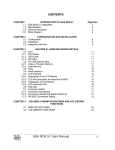
A. EDU-ARM7-2148 Block Diagram:
Below figure shows the locations of different components on the EDU-ARM7-2148
board.
Below figure shows the locations of different switches and jumpers on the EDUARM7-2148 board.
7
B. Switches Details:
S1:
Turn ON this switch to connect USB device connector to USB lines of LPC2148.
S2:
Turn ON this switch to connect UART1 connector to UART1 lines (TxD1/P0.8 and
RxD1/P0.9) of LPC2148.
S3:
Mode selection switch. The LPC21xx micro-controllers include on-chip flash for
storing user program and non-volatile data. The LPC2148 have 512KBytes flash. This flash
is In-System-Programmable (ISP). The LPC21xx micro-controllers have a built-in boot-load
program. Upon power-on, this bootload program takes control; it passes control to the user
program if pin P0.14 is HIGH and some other conditions are satisfied. Please refer to the
LPC21xx data-sheet for further details. On the EDU-ARM7-2148 board, the P0.14 pin is
made available on this S3 switch. Turn ON this switch to control the Mode (ISP mode or
Run mode) by Flash Magic.
S4:
Turn ON this switch to connect Seven Segments, RTC (DS1307) and EEPROM
(AT24C512) to I2C lines (SCL0/P0.2 and SDA0/P0.3) of LPC2148.
S5:
Turn ON this switch to connect POT and LM35 to ADC0.1/P0.28 and ADC0.2/P0.29
of LPC2148.
S6:
Turn ON this switch to connect Buzzer, DAC/TP7 and External Interrupt to
ACOut/P0.25 and EINT0/P0.16 of LPC2148.
S7:
Turn ON this switch to connect SPI EEPROM (AT25256) to SPI lines (SCK0/P0.4,
MISO0/P0.5, MOSI0/P0.6 and CS/P0.7) of LPC2148.
8
C. Connector Details:
UART0:
This is a DB9 female connector, used for RS232 serial communication with the PC:
Pin 2 = UART0 RS232 TxD (output of mC)
Pin 3 = UART0 RS232 RxD (input to mC)
Pin 4 = RS232 DTR
Pin 5 = Ground
Pin 7 = RS232 RTS
All other pins of J1/UART0 are unused.
UART1:
This is a DB9 female connector, used for RS232 serial communication with the PC:
Pin 2 = UART1 RS232 TxD (output of mC)
Pin 3 = UART1 RS232 RxD (input to mC)
Pin 5 = Ground
16x2 LCD:
This is a 16 pin, single line connector, designed for connection to standard, text LCD
modules. The pin/signal correspondence is designed to be matching with that required by
such LCD modules.
Pin 1 = GND
Pin 2 = +5V
Pin 3 = Vlcd
Pin 4 = P1.25 (Used as RS of LCD)
Pin 5 = GND
Pin 6 = P1.24 (Used as EN of LCD)
Pin 7 to 10 = No Connection
Pin 11 = P0.15 (Used as D4 of LCD)
Pin 12 = P0.17 (Used as D5 of LCD)
Pin 13 = P0.22 (Used as D6 of LCD)
Pin 14 = P0.30 (Used as D7 of LCD)
Pin 15 = Backlighting
Pin 16 = GND
128x64 Graphics LCD:
This is a 20 pin, single line connector, designed for connection to standard, 128x64
Monochrome Graphics LCD modules. The pin/signal correspondence is designed to be
matching with that required by such LCD modules.
Pin 1 = GND
Pin 2 = +5V
Pin 3 = Vlcd
Pin 4 = P1.25 (Used as RS of GLCD)
Pin 5 = P0.15 (Used as RW of GLCD)
Pin 6 = P1.24 (Used as EN of GLCD)
Pin 7 = P0.10 (Used as D0 of GLCD)
Pin 8 = P0.11 (Used as D1 of GLCD)
Pin 9 = P0.12 (Used as D2 of GLCD)
Pin 10 = P0.13 (Used as D3 of GLCD)
Pin 11 = P0.18 (Used as D4 of GLCD)
Pin 12 = P0.19 (Used as D5 of GLCD)
9
Pin 13 = P0.20 (Used as D6 of GLCD)
Pin 14 = P0.21 (Used as D7 of GLCD)
Pin 15 = P0.22 (Used as CS1 of GLCD)
Pin 16 = P0.30 (Used as CS2 of GLCD)
Pin 17 =
Pin 18 =
Pin 19 = +5V
Pin 20 = GND
JTAG Connector:
This standard 20 pin JTAG connector provides debugging support for the LPC21xx.
This connector is mounted on top side of the board as shown in figure1. JTAG cables like
SJT-S or SJT-U can be connected to this connector, while other end of the cable can be
connected to PC COM port or USB port, respectively. Debugger software (like the debugger
built into SCARM) allows JTAG based debugging. It is also possible to use third party JTAG
based emulators /debuggers. The pin-out of JTAG Connector is given below:
J7:
This is 26 pin dual line headers. It brings out I/O and most of the pins of the LPC21xx
micro-controller. Further, 5V and GND are also made available on these connectors. These
connectors are intended for use to connect external peripherals.
The pin/signal details of J7 are as below:
10
11
Study experiment:2
Aim
:- Study of IDE overview (Project creation, downloading & debugging)
Apparatus
:- EDU-ARM-2148 Trainer kit.
Theory
:-
A. SCARM Installation:
As a part of the SCARM software package, you should have received a CDROM.
Please insert it into the CD-ROM drive and run SETUP.EXE from it. Once you start the
SETUP program, follow the instructions on the screen to complete the installation. The
setup program will:
Copy the required files to your hard disk
If there are any compressed files, un-compress them
Create a program group for SCARM
Once you have successfully installed the software on your hard disk, you can run it by
clicking on
Start/Programs/SPJ - SCARM/SIDEARM. However, we recommend, that you go through
this user’s manual before you actually start using it.
SCARM is SPJETs’ C Compiler for ARM. It also includes an IDE and other tools like
Debugger, Visual Code Generator (VCG) and Terminal Emulation Utility (SPJTerm).
This document describes steps to create ARM applications in C using the SCARM.
About “Project”:
What is a project?
A project is a file in which SIDEARM stores all information related to an application. E.g. it
stores the name(s) of ‘C’ and/or Assembler source file(s), memory size to be used and other
options for compiler, assembler and linker.
Opening a project:
To open an existing project file, select Project / Open Project from the menu.
Creating a new project:
To create a new project, select Project / New Project from the menu.
Changing project settings:
To change the project settings (such as adding or removing ‘C’ and/or Assembler source
file(s), changing memory settings etc.), select Project / Settings from the menu.
B. SCARM Quick Start for creating ‘C’ applications:
1. Start the SIDE_ARM program (i.e. the Integrated Development Environment) from
start\Programs\SPJ-SCARM.
2. From Project menu, select Close project (if any project is open).
3. From Project menu, select New Project. The Open dialog window will be displayed.
Select the desired path where you wish to create this new project. (For example, C:\SPJ).
12
CAUTION: The path and filename must not contain space or other special characters such
as tab, comma, semicolon etc. In the “File name” field, type the name of the project, without
any extension. For example, you may type “PROG1”. Then click on the “Open” button.
4. The action in the previous step will display the “Project Settings” dialog window. This
dialog window has 3 different parts named “Compiler Options”, “Linker Options”, and
“Source Files”. Any of these 3 parts can be displayed by clicking on the corresponding
name near the top of this dialog window. Currently, the “Compiler Options” will be
automatically displayed. If the target micro-controller (must be a member of ARM family) is
known, you may select the appropriate Manufacturer from the list; and then select the
appropriate micro-controller from the device list. If the target micro-controller is not known or
if you cannot find it in the list, then you may simply select “Philips” as the manufacturer and
“LPC2148” as the micro-controller.
5. Click on “Linker Options” to display that part of the dialog window. In this window, you
will see a list of 8 “Memory Banks”, with names such as “Memory #1”, “Memory #2” and so
on. In your target hardware, there may be none or 1 or more number of contiguous memory
blocks connected to the ARM micro-controller. Check the appropriate number of memory
banks to reflect the target’s memory blocks. For each checked memory bank, specify
memory start address (in Hexadecimal) and memory block size (in decimal). Size maybe
specified either in number of Kilobytes (KB) or Megabytes (MB). Some of the memory
blocks maybe “read-only” (e.g. flash or conventional EPROM). Accordingly, you may check
or uncheck the “Read only” box. Based on this information about memory banks, the IDE
will automatically create the Linker Script. This auto-generated script is adequate for most
users. However, if you wish to use your own script file instead of this autogenerated script,
you may check the “Use different linker script” box and further click on the browse button
(marked “0”) and select appropriate linker script file.
6. Click on “Source Files” to display that part of the dialog window. This window will indicate
that IDE has automatically added 2 files in this new project: PROG1.C and STARTUP.ASM.
The STARTUP.ASM file is automatically created by the IDE and is required for all C
projects. Similarly, the IDE has automatically created an empty C file (PROG1.C). If the file
PROG1.C already exists in the same path, then IDE would neither create/overwrite it nor
modify it; but it will anyway add it to the project automatically. If you wish to add more files in
this project, then click on the “Add file” button, select the desired filename and then click on
“Open” button. Now the Project Settings dialog will indicate that selected file has been
added into the project. When all necessary files have been added to the project, click “OK”
button to create this new project.
7. The PROG1.C file created by the IDE will be an empty file containing only the frame of
“main” function. You may write the desired program statements in this file (or other files that
you may have added to the project). When done, select Save from File menu. If you have
modified more than one source files, then select Save All from File menu.
8. From the Compile menu, select Build. This will invoke the Compiler to compile the file
PROG1.C; and further (assuming no errors) invoke the linker to create the .HEX file. If there
are any errors or warnings during the process of compiling, assembling or linking, then
those will be displayed in the output window (below the editor window). If there are errors,
then you may correct those by making appropriate changes to the program; select Save
13
from File menu to save the changes and then again select Build from Compile menu.
Repeat this until there are no errors.
9. You may inspect contents of the folder where your project files reside. When there are no
errors and build has completed successfully and then you will see a filename with same
name as the project name and extension .HEX (in above example, PROG1.HEX). This is
the file that you will need to use to program your micro-controller.
C. Downloading & Running Programs:
The LPC2148 micro-controllers include on-chip flash for storing user program and nonvolatile data. LPC2148 on EDU-ARM7-2148 have 512KBytes flash. This flash is In-SystemProgrammable (ISP). Therefore it is possible to download user program into on-chip flash of
LPC2148, through serial port connected to PC. For doing so, a certain position of S3 switch
is required. S3 Switch should be continuously ON. This section describes how to use the
software Flash Magic to download program into LPC2148.
1. How to install Flash Magic:
The CD you have received with this board contains SCARM, C Compiler for ARM.
Install it. After installation go to folder C:\SCARM\Utilities. This folder contains 5 zip files.
Install Flash Magic from FlashMagic3.71.zip. Extract the FlashMagic3.71.zip and then run
FlashMagic.exe from the extracted files. (If you have wrong version of Flash Magic already
installed, then please uninstall it first and then install new version).
2. Download and Run program using Flash Magic into LPC2148:
After installation of Flash Magic, open it.
In Flash Magic go to Options -> Advanced Options-> Communications. Check High Speed
Communications and keep Maximum Baud Rate as 19200. Click on OK.
Again in Flash Magic go to Options -> Advanced Options-> Hardware Config. “Use DTR
and RTS to control RST and P0.14” option should be checked. Click on OK.
(After doing above mentioned settings, Flash Magic stores it means for the next time just
verify if these setting are proper or not. If they are proper then you can directly follow below
mentioned procedure)
a) Connect the J1/UART0 connector of EDU-ARM7-2148 board to COM1 or COM2 of a PC,
using the serial communication cable (supplied with the board).
b) Keep S3 switch in ON position. (You can keep S3 switch continuously ON) Switch ON
power to the EDU-ARM7-2148.
c) Do proper settings in Flash Magic (COM Port: COM1 (if other choose it), Baud Rate:
38400, Device: LPC2148, Interface: None (ISP), Enable “Erase blocks used by Hex File”,
Browse the file which you want to download) and click on Start button.
d) Flash Magic will download the program. Wait till Finished comes.
e) After downloading Flash Magic automatically resets the EDU-ARM7-2148 board and
program executes. You can see output according to the program.
f) If again you want to Reset the board then Switch OFF and ON the power to the EDUARM7- 2148 board. You can see output according to the program.
Note: Flash Magic can be used to download the program into other Philips Microcontrollers
also. See the list in Flash Magic itself.
14
Study experiment:3
Aim
:-Study of JTAG Debugger.
Apparatus
:- EDU-ARM-2148 Trainer kit.
Theory
:-
A. JTAG Cable for Debugging:
1. Type:
SJT-S: Serial JTAG Cable.
2. Contents:
The “JTAG Cable” consists of following parts:
Dongle (a small box with connectors on both ends).
Cable
The “dongle” consists of some electronic circuit for interfacing the JTAG port of target
processor to the host computer. The cable is a bunch of wires to connect the dongle with
the JTAG port of target.
3. Power Supply Requirements:
The JTAG cable draws power from the target board. Thus it does not require a
separate power source.
4. Connecting JTAG Cable:
SJT-S:
There is a DB9 female connector on one end of the dongle. This directly mates with
the PC COM port –which has a DB9 male connector (or you can connect yellow color serial
cable supplied with SJT-S between DB9 female connector on one end of the dongle and PC
COM port –which has a DB9 male connector). The other end of the dongle has DB25
female connector. There is a DB25 male connector on one end of the cable. These DB25
female and DB25 male connectors are designed to mate with each other directly. The other
end of the cable has a 20-pin header. This should be connected to the JTAG connector of
the target board.
CAUTION:
The JTAG Cable must not be connected or dis-connected when power is applied to the
target board. Turn off power to the target board, connect the JTAG Cable and then you may
turn on power to the target board. Connecting the JTAG Cable with incorrect polarity /
orientation may permanently damage the EDUARM7- 2148 board and/or the JTAG Cable. It
will also make the warranty void for both the products.
B. Verifying correct cable connection:
When the JTAG Cable is correctly connected to PC as well as the target board, it
serves as a link between the JTAG port of target processor and the PC. This link is used by
SPJ - SCARM software Tools (e.g. Debugger for ARM microcontrollers). This software tool,
Debugger will work correctly only when the JTAG Cable is connected correctly.
For SJT-S:
There is a crude test to verify SJT-S JTAG Cable connection. You may please follow these
steps:
15
1. Connect JTAG Cable between PC COM port and EDU-ARM7-2148, as per instructions in
this manual.
2. Turn ON power to the target board.
3. On the PC, run SPJTerminal software.
4. In the Port Settings, select appropriate COM port (to which the JTAG cable is connected).
Select 115200 baud, no parity, 8 bits per char, 1 stop bit and no flow control.
5. Open the COM Port connection.
6. Type character ‘G’ in the terminal window. I.e. send the character ‘G’ to the PC COM port.
7. If the JTAG Cable connection is correct, it will send back character ‘1’ or ‘0’. As a result,
you will see either ‘1’ or ‘0’ appearing in the terminal window. This indicates that JTAG
Cable connection is ok.
8. If you don’t see any character in the terminal window, probably the JTAG Cable is not
connected appropriately.
9. If you see some character other than ‘1’ and ‘0’, then either the cable is not connected
appropriately or the COM port settings are not as specified above.
C. How to Debug Program:
1. Connect SJT-S as mentioned above.
2. Open project in SIDEARM. Rebuild it.
3. Download the same code in the target board.
4. In SIDEARM go to Tools -> Debugger.
5. In Debugger go to Run -> Click on “Not connected to target (click here to connect)”.
6. Device ID starting from 0x4........ will be displayed and program will run.
7. To stop program go to Run -> Stop. Now you can insert breakpoint and say Run.
8. You can use all the functions visible in Run option.
9. In variable watch window you can see only global variables.
10. If you have declared any global variables then find their addresses from .map file.
11. Insert these addresses in variable watch window and you can see global variables also.
16
Experiment No. 4 :
Aim
:- Write a program for serial communication using UART0.W.A.P. to transfer
message “Hello World !” serially at 19200 –baud rate 8-bit data and 1 stop bit using UART0.
Apparatus
:- EDU-ARM-2148 Trainer kit,SCRAM,PC
Theory
:-Write
theory related to serial communication using UART0.
Block Diagram:J1
EDU-ARM7-2148
PC
Serial Cable
Programm:- Program is given along with the compiler software.
Source Code:
#include <Philips\LPC2148.h>
#include <stdio.h>
void main ()
{
PINSEL0 = 0x00000005 ;
InitUart0();
printf("Hello World! \n");
while(1)
{
putchar(getchar());
}
}
Function: UART0
#include <Philips\LPC2148.h>
//#include <Philips\LPC2138.h>
#define
VPBDIV
(*((volatile WORD32 *) 0xE01FC100))
#define
U0RBR
(*((volatile WORD32 *) 0xE000C000))
#define DESIRED_BAUDRATE 19200
#define CRYSTAL_FREQUENCY_IN_HZ 12000000
#define PCLK CRYSTAL_FREQUENCY_IN_HZ
/* since VPBDIV=0x01
#define DIVISOR (PCLK/(16*DESIRED_BAUDRATE))
void InitUart0(void)
*/
17
{
/*
/*
U0LCR: UART0 Line Control Register
0x83: enable Divisor Latch access, set 8-bit word length,
1 stop bit, no parity, disable break transmission
*/
U0LCR=0x83;
VPBDIV: VPB bus clock divider
0x01: PCLK = processor clock
VPBDIV=0x01;
*/
/*
U0DLL: UART0 Divisor Latch (LSB)
U0DLL=DIVISOR&0xFF;
*/
/*
U0DLM: UART0 Divisor Latch (MSB)
U0DLM=DIVISOR>>8;
*/
/*
U0LCR: UART0 Line Control Register
0x03: same as above, but disable Divisor Latch access
U0LCR=0x03 ;
*/
U0FCR: UART0 FIFO Control Register
0x05: Clear Tx FIFO and enable Rx and Tx FIFOs
U0FCR=0x05 ;
*/
/*
}
char putchar(char ch)
{
if (ch=='\n')
{
//wait until Transmit Holding Register is empty
while (!(U0LSR&0x20)) {}
//then store to Transmit Holding Register
U0THR='\r';
}
//wait until Transmit Holding Register is empty
while (!(U0LSR&0x20)) {}
//then store to Transmit Holding Register
U0THR=ch;
return ch;
}
char getchar(void)
{
char ch;
//wait until there's a character to be read
while (!(U0LSR&0x01)) {}
//then read from the Receiver Buffer Register
ch=U0RBR;
return ch;
}
Output: You can see output on SPJ Terminal.
18
Experiment No. 5:
Aim
: Write
a program to interface LCD.
Apparatus
:- EDU-ARM-2148 Trainer kit with 16x2 LCD,SCRAM,PC
Theory
:- Write theory related to LDC Interfacing with ARM Processors.
Block Diagram:J1/UART0
J1
[16x2 LCD]
EDU-ARM7-2148
PC
Serial Cable
Programm:- Program is given along with the compiler software.
Source Code:
#include <Philips\LPC2148.h>
#include "lcd.h"
void main ()
{
LcdInit();
DisplayRow (1," JNEC ");
DisplayRow (2," Aurangabad ");
while(1)
{}
}
Function: LCD
#include <Philips\LPC2148.h>
#include "lcd.h"
void SmallDelay (void)
{
int i;
for(i=0;i<100;i++);
}
void LcdCmd1 (unsigned char cmd)
{
if (cmd & 0x01)
IO0SET = (1<<15);
else
IO0CLR = (1<<15);
19
if (cmd & 0x02)
IO0SET = (1<<17);
else
IO0CLR = (1<<17);
if (cmd & 0x04)
IO0SET = (1<<22);
else
IO0CLR = (1<<22);
if (cmd & 0x08)
IO0SET = (1<<30);
else
IO0CLR = (1<<30);
IO1CLR = 0x03000000 ; // make rs and en low
SmallDelay() ;
IO1SET = 0x01000000 ; // enable en
SmallDelay() ;
IO1CLR = 0x01000000 ; // disable en
SmallDelay() ;
}
void LcdDat1 (unsigned char dat)
{
if (dat & 0x01)
IO0SET = (1<<15);
else
IO0CLR = (1<<15);
if (dat & 0x02)
IO0SET = (1<<17);
else
IO0CLR = (1<<17);
if (dat & 0x04)
IO0SET = (1<<22);
else
IO0CLR = (1<<22);
if (dat & 0x08)
IO0SET = (1<<30);
else
IO0CLR = (1<<30);
IO1SET = 0x02000000 ; // make RS high
SmallDelay() ;
IO1CLR = 0x01000000 ; // disable en
SmallDelay() ;
IO1SET = 0x01000000 ; // enable en
SmallDelay() ;
IO1CLR = 0x01000000 ; // disable en
SmallDelay() ;
}
void Delay250 (void)
{
int k,j ;
20
j =200 ;
for(k = 0 ; k < 100 ; k ++)
{
j-- ;
}
}
void DelayMs (int n)
{
int k ;
for(k = 0 ; k < n ; k ++)
{
Delay250() ;
Delay250() ;
}
}
void LcdCmd (unsigned char cmd)
{
LcdCmd1(cmd >> 4) ;
LcdCmd1(cmd) ;
Delay250() ;
Delay250() ;
}
void LcdDat (unsigned char dat)
{
LcdDat1(dat >> 4) ;
LcdDat1(dat) ;
Delay250() ;
Delay250() ;
}
void LcdInit (void)
{
IO1DIR = 0x03000000 ;
IO1CLR = 0x03000000 ;
IO0DIR = 0x40428000 ;
IO0CLR = 0x40428000 ;
DelayMs(6) ;
LcdCmd1(0x03) ;
DelayMs(6) ;
LcdCmd1(0x03) ;
Delay250() ;
LcdCmd1(0x03) ;
Delay250() ;
LcdCmd1(0x02) ;
Delay250() ;
LcdCmd(0x28) ;
LcdCmd(0x08) ;
LcdCmd(0x0c) ;
LcdCmd(0x06) ;
21
}
void DisplayRow (int row, char *str)
{
/*
pass pointer to 16 character string
displayes the message on line1 or line2 of LCD, depending on whether row is 1 or 2.
*/
int k ;
if (row == 1)
LcdCmd(0x80) ;
else
LcdCmd(0xc0) ;
for(k = 0 ; k < 16 ; k ++)
{
if (str[k])
LcdDat(str[k]) ;
else
break ;
}
while(k < 16)
{
LcdDat(' ') ;
k ++ ;
}
}
Output: You can see the message Hello World on LCD.If required reset the board.
22
Experiment No. 6
Aim
: Write a program to Blink LED ‘s present on EDU-ARM-2148.
Apparatus
:- EDU-ARM-2148 Trainer kit ,SCRAM,PC
Theory
:- Write theory related to LED interfacing using ARM.
Block Diagram:-
J1
[8 General Purpose
LEDs]
EDU-ARM7-2148
PC
Serial Cable
Programs:- Program is given along with the compiler software.
Source Code:
#include <Philips\LPC2148.h>
#include <stdio.h>
void main ()
{
PINSEL0 = 0x00000005 ;
InitUart0();
printf("Hello World! \n");
while(1)
{
putchar(getchar());
}
}
Output: You can see the message Hello World on LCD.If required reset the board.
23
Experiment No.7
Aim
:Write a program to interface Stepper motor.
Apparatus :EDUARM2148 with stepper motor Trainer kit ,SCRAM,PC
Theory
:Write theory related to stepper motor interfacing.
Block Diagram:-
Programm:- Program is given along with the compiler software.
Source Code:
#include <Philips\LPC2148.h>
#define PHASEA 0x00002400
#define PHASEB 0x00001400
#define PHASEC 0x00001800
#define PHASED 0x00002800
unsigned int delay ;
void main ()
{
PINSEL0 = 0x00000000 ;
PINSEL1 = 0x00000000 ;
IO0DIR = 0x003C3C00 ;
IO0SET = 0x003C0000 ;
/PINSEL2 = 0x00000000 ;
/IO1DIR = 0x00000000 ;
while(1)
{
IO0SET = PHASEA ;
IO0CLR = (~PHASEA) & 0x00003C00 ;
for(delay=0; delay<30000; delay++) ;
IO0SET = PHASEB ;
IO0CLR = (~PHASEB) & 0x00003C00 ;
for(delay=0; delay<30000; delay++) ;
IO0SET = PHASEC ;
24
IO0CLR = (~PHASEC) & 0x00003C00 ;
for(delay=0; delay<30000; delay++) ;
IO0SET = PHASED ;
IO0CLR = (~PHASED) & 0x00003C00 ;
for(delay=0; delay<30000; delay++) ;
}
}
Output: You can see stepper motor moving in particular direction and corresponding phase
changes you can observed LED’s D9-D12.
25
Experiment No.8
Aim
: Write a program to interface buzzer with LPC2148.
Apparatus
:- EDU-ARM-2148 with buzzer Trainer kit ,SCRAM,PC
Theory
:- Write theory related to relay interfacing.
Block Diagram:-
J1
[buzzer]
EDU-ARM7-2148
PC
X
5
Serial Cable
Programme:-
#include <Philips\LPC2148.h>
#include "uart0.h"
#include "TYPE.h"
unsigned int i;
void main ()
{
PINSEL0 = 0x00000000 ;
PINSEL1 = 0x00000000 ;
IO0DIR |= 0x023C3C00 ;
UART0_Init();
while(1)
{
//printf("Press any key\n");
//getchar();
26
for(i=0;i<30000;i++)//delay
{}
IO0SET = 0x023C3C00 ;//making these pin as 1
for(i=0;i<30000;i++)
{}
//printf("press any key\n");
//getchar();
IO0CLR=0x023C3C00;//clearing the pins as 0
for(i=0;i<30000;i++)
{}
} }
Output: Thus we got output as buzzer sound.
27
.
4. Quiz on the subject
1. Write short notes on:
a. Priority Scheduling
b. Multitasking
c. Seamthort
5. Conduction of Viva-Voce Examination:
Teacher should conduct oral exams of student with full preparation. Normally the
objective questions with guesses are to be avoided. To make it meaningful, the
questions should be such that depth of the students in the subject is tested. Oral
examinations are to be conducted in cordial environment amongst the teacher taking
the examination. Teachers taking such examinations should not have ill thoughts
about each other and courtesies should be offered to each other in case of difference
of opinion, which should be critically suppressed in front of the students.
6. Evaluation and Marking systems:
Basic honesty in the evaluation and marking system is absolutely essential and in the
process impartial nature of the evaluator is required in the examination system to
become successful. It is wrong approach or concept to award the students by way of
easy making to get cheap popularity among the students which they do not deserve.
It is a primary responsibility of the teacher to see that right students are really putting
up lot of hard work with right kind of intelligence are correctly awarded.
The marking pattern should be justifiable to the students without any ambiguity and
teacher should see that the students are faced with just circumstances.
28