1
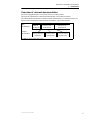
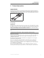
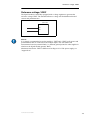
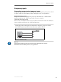
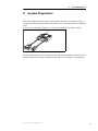
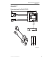
IQAN-XC22/23 Instruction book Publ no HY33-8412-IB/UK Edition 2015-12-17 Contents 1 Introduction . . . . . . . . . . . . . . . . . . . . . . . . . . . . . . . . . . . . . . . . . . . . . . . . . . . . 1 Warnings . . . . . . . . . . . . . . . . . . . . . . . . . . . . . . . . . . . . . . . . . . . . . . . . . . . . 1 Overview of relevant documentation . . . . . . . . . . . . . . . . . . . . . . . . . . . . . . . 2 2 Precautions . . . . . . . . . . . . . . . . . . . . . . . . . . . . . . . . . . . . . . . . . . . . . . . . . . . . 3 Read This . . . . . . . . . . . . . . . . . . . . . . . . . . . . . . . . . . . . . . . . . . . . . . . . . . . . 3 Design of control system . . . . . . . . . . . . . . . . . . . . . . . . . . . . . . . . . . . . . 3 Start-up, maintenance, and diagnostics . . . . . . . . . . . . . . . . . . . . . . . . . 4 3 Product description . . . . . . . . . . . . . . . . . . . . . . . . . . . . . . . . . . . . . . . . . . . . . 5 IQAN-XC22/23 . . . . . . . . . . . . . . . . . . . . . . . . . . . . . . . . . . . . . . . . . . . . . . . . 5 I/O overview . . . . . . . . . . . . . . . . . . . . . . . . . . . . . . . . . . . . . . . . . . . . . . 5 CAN related functions . . . . . . . . . . . . . . . . . . . . . . . . . . . . . . . . . . . . . . . 6 4 Safety . . . . . . . . . . . . . . . . . . . . . . . . . . . . . . . . . . . . . . . . . . . . . . . . . . . . . . . . . 7 Internal diagnostics . . . . . . . . . . . . . . . . . . . . . . . . . . . . . . . . . . . . . . . . . . . . 7 CAN-bus interruption . . . . . . . . . . . . . . . . . . . . . . . . . . . . . . . . . . . . . . . . . . . 7 Current check . . . . . . . . . . . . . . . . . . . . . . . . . . . . . . . . . . . . . . . . . . . . . . . . . 7 Emergency stop . . . . . . . . . . . . . . . . . . . . . . . . . . . . . . . . . . . . . . . . . . . . . . . 7 5 Mounting . . . . . . . . . . . . . . . . . . . . . . . . . . . . . . . . . . . . . . . . . . . . . . . . . . . . . . 8 Mounting the module . . . . . . . . . . . . . . . . . . . . . . . . . . . . . . . . . . . . . . . . . . . 8 Assembling of the ID-Tag . . . . . . . . . . . . . . . . . . . . . . . . . . . . . . . . . . . . 8 6 Installation . . . . . . . . . . . . . . . . . . . . . . . . . . . . . . . . . . . . . . . . . . . . . . . . . . . . . 9 Connector C1, C2, and C3 . . . . . . . . . . . . . . . . . . . . . . . . . . . . . . . . . . . . . . . 9 Connector C1 pin assignments, -XC22 and -XC23 . . . . . . . . . . . . . . . . . 9 Connector C2 pin assignments, -XC23 (-XC22 does not have a C2), . 10 Connector C3 pin assignments, -XC22 / -XC23 . . . . . . . . . . . . . . . . . . 10 Supply voltage . . . . . . . . . . . . . . . . . . . . . . . . . . . . . . . . . . . . . . . . . . . . . . . 11 Emergency stop . . . . . . . . . . . . . . . . . . . . . . . . . . . . . . . . . . . . . . . . . . 11 Connecting of Supply Voltage . . . . . . . . . . . . . . . . . . . . . . . . . . . . . . . . 11 Polarity reversal . . . . . . . . . . . . . . . . . . . . . . . . . . . . . . . . . . . . . . . . . . 11 Addressing/terminating . . . . . . . . . . . . . . . . . . . . . . . . . . . . . . . . . . . . . . . . 12 Addressing . . . . . . . . . . . . . . . . . . . . . . . . . . . . . . . . . . . . . . . . . . . . . . 12 Terminating . . . . . . . . . . . . . . . . . . . . . . . . . . . . . . . . . . . . . . . . . . . . . . 12 Reference voltage, VREF . . . . . . . . . . . . . . . . . . . . . . . . . . . . . . . . . . . . . . 13 Voltage inputs . . . . . . . . . . . . . . . . . . . . . . . . . . . . . . . . . . . . . . . . . . . . . . . 14 Connecting sensors to the voltage inputs . . . . . . . . . . . . . . . . . . . . . . . 14 Connecting a 2-wire temperature sensor to voltage in . . . . . . . . . . . . . 15 Connecting switches to the voltage inputs using VREF . . . . . . . . . . . . 15 Connecting switches to the voltage inputs using +BAT . . . . . . . . . . . . 16 Frequency inputs . . . . . . . . . . . . . . . . . . . . . . . . . . . . . . . . . . . . . . . . . . . . . 17 Connecting sensors to the frequency inputs . . . . . . . . . . . . . . . . . . . . . 17 Directional frequency inputs . . . . . . . . . . . . . . . . . . . . . . . . . . . . . . . . . . . . . 18 Connecting sensors to the directional frequency inputs . . . . . . . . . . . . 18 Low-side digital outputs . . . . . . . . . . . . . . . . . . . . . . . . . . . . . . . . . . . . . . . . 19 PWM inputs . . . . . . . . . . . . . . . . . . . . . . . . . . . . . . . . . . . . . . . . . . . . . . . . . 20 Connecting PWM sensor . . . . . . . . . . . . . . . . . . . . . . . . . . . . . . . . . . . 20 7 Start-up . . . . . . . . . . . . . . . . . . . . . . . . . . . . . . . . . . . . . . . . . . . . . . . . . . . . . . . 21 Start-up procedures . . . . . . . . . . . . . . . . . . . . . . . . . . . . . . . . . . . . . . . . . . . 21 Starting the control system . . . . . . . . . . . . . . . . . . . . . . . . . . . . . . . . . . 21 Prepare for system start . . . . . . . . . . . . . . . . . . . . . . . . . . . . . . . . . . . . 21 Start the system . . . . . . . . . . . . . . . . . . . . . . . . . . . . . . . . . . . . . . . . . . 21 Instruction book, IQAN-XC22/23 ii Contents 8 System Diagnostics . . . . . . . . . . . . . . . . . . . . . . . . . . . . . . . . . . . . . . . . . . . . 22 Appendix A . . . . . . . . . . . . . . . . . . . . . . . . . . . . . . . . . . . . . . . . . . . . . . . . . . . 23 IQAN-XC22/23 Technical Overview . . . . . . . . . . . . . . . . . . . . . . . . . . . . . . . 23 Appendix B . . . . . . . . . . . . . . . . . . . . . . . . . . . . . . . . . . . . . . . . . . . . . . . . . . . 27 Error codes, messages and actions . . . . . . . . . . . . . . . . . . . . . . . . . . . . . . . 27 LED indicator showing different XC22/23 modes . . . . . . . . . . . . . . . . . 27 Appendix C . . . . . . . . . . . . . . . . . . . . . . . . . . . . . . . . . . . . . . . . . . . . . . . . . . . 28 Dimensioning of the IQAN-XC22/23 . . . . . . . . . . . . . . . . . . . . . . . . . . . . . . 28 Instruction book, IQAN-XC22/23 iii Warnings 1 1 Introduction Introduction These instructions are to be used as a reference tool for the vehicle manufacturer’s design, production, and service personnel. The user of these instructions should have basic knowledge in the handling of electronic equipment. Warnings Sections marked with a symbol in the left margin, must be read and understood by everyone using the system, carrying out service work, or making changes to hardware and software. The different symbols used in this manual are defined below. WARNING Sections labeled WARNING with a caution symbol in the left margin, indicate that a hazardous situation exists. We use warnings, marked with the warning symbol, in two ways. • As a strong recommendation about work practices when using the product in the machine (e.g. routines when updating an application). This use is common to the term 'hazardous situation', that a person is exposed to a hazard. • As a way of pointing out important information for the machine designer that in some way relates to safety. This includes the design of the physical machine, and also the application program being developed for the control system. Not all document sections that contain information about safety are marked with a warning symbol (there would be warnings everywhere). Failure to comply with the recommendations can cause unintentional, and unexpected behavior of the control system. This can potentially cause death, serious injury or property damage. N OTICE Sections labeled NOTICE with a notice symbol in the left margin, indicate there is important information about the product. Ignoring this could result in less than optimal performance, or damage to the product. Contact the manufacturer if there is anything you are not sure about or if you have any questions regarding the product and its handling or maintenance. The term "manufacturer" refers to Parker Hannifin Corporation. Instruction book, IQAN 1 Overview of relevant documentation 1 Introduction Overview of relevant documentation The following publications are relevant for users of this product. The main documentation contains information that is not found elsewhere. The additional documentation contains product information in a compact format, for details on the information found in those documents, consult this manual. Main Documentation Compact Documentation IQANdesign/ IQANrun User Manuals IQAN module Instruction Book HY33-8nnn-IB IQAN module Catalogue Datasheet HY33-8nnn Mounting and Maintenance Instruction Book HY33-8327-IB IQAN module Installation Sheet HY33-8nnn-IS IQAN module Electrical Schematic HY33-8nnn-ES The IQAN module documentation system. Instruction book, IQAN 2 Read This 2 2 Precautions Precautions Work on the hydraulics control electronics may only be carried out by trained personnel who are well-acquainted with the control system, the machine and its safety regulations. WARNING Make sure that you have sufficient knowledge before designing, modifiying or servicing the control system. Read the relevant sections of this document before conducting any work on the control system. WARNING This product is not field repairable. N OTICE As much as possible of the welding work on the chassis should be done before the installation of the system. If welding has to be done afterwards, the electrical connections on the system must be disconnected from other equipment. The negative cable must always be disconnected from the battery before disconnecting the positive cable. The ground wire of the welder shall be positioned as close as possible to the place of the welding. The cables on the welding unit shall never be placed near the electrical wires of the control system. Read This Design of control system WARNING Risk of injury may be introduced by design of control system! This product is designed to control hydraulic outputs. The control application must be designed using basic safety principles so that unintentional movement is avoided. The machine must be equipped with an emergency stop that stops all movement. Please refer to section "Supply voltage". Before you start Read this document. Read the IQANdesign software user manual section on 'application safety'. Instruction book, IQAN 3 Read This 2 Precautions Start-up, maintenance, and diagnostics For all personnel carrying out installation, commissioning, maintenance or troubleshooting. WARNING Work on the hydraulics control electronics may only be carried out by trained personnel who are well-acquainted with the control system, the machine and its safety regulations. Before you start, Read section "Start-up". Additional information for service Mounting and maintenance instruction book. Additional information for diagnosing the system Read section "System diagnostics", and see "Appendix B", in this document. Use the IQANrun software user manual as a reference. Instruction book, IQAN 4 IQAN-XC22/23 3 3 Product description Product description IQAN-XC22/23 The IQAN-XC22 and XC23 are stackable, flexible expansion modules designed as a signal input module for use outdoors, using 12/24 Vdc power supply. The XC22 has 2 keyed Deutsch DTM connectors and the XC23 has 3 keyed Deutsch DTM connectors IQAN-XC22 modules I/O overview Voltage inputs The IQAN-XC22 module does not have any voltage inputs. The IQAN-XC23 module has eight (8) voltage inputs VIN-A thru VIN-H for connection of 0-5 Vdc signals. The inputs are multi-purpose and may be configured as digital inputs DIN-M thru DIN-T. Voltage inputs and digital inputs share positions, see below. (8) Voltage inputs VIN-A, VIN-B, VIN-C.....VIN-H or (8) Digital inputs DIN-M, DIN-N.....DIN-T use positions VIN-A thru VIN-H Digital inputs and outputs The XC22 and XC23 modules have twelve (12) digital inputs DIN-A thru DIN-L for connection of on/off signals. Most of these inputs are multi purpose and can be configured in other ways. The eight (8) digital inputs DIN-A thru DIN-H can configured as low-side digital outputs DOUT-A thru DOUT-H. The ten (10) inputs DIN-J, DIN-K and DIN-A thru DIN-H can be configured as frequency inputs FIN-A thru FIN-J or pulse count inputs PCNT-A thru PCNT-J. The three (3) inputs DIN-A thru DIN-C can be configured as pulse width modulation inputs PWMIN-A thru PWMIN-C. The two (2) inputs DIN-K and DIN-L can be configured as quadrature input for measuring directional frequency input DFIN-A or directional pulse count DPCNT-A. Instruction book, IQAN-XC22/23 5 IQAN-XC22/23 3 Product description Digital inputs, digital outputs, frequency inputs, pulse count inputs, pulse width modulation inputs and quadrature inputs share positions, see below. (12) digital inputs DIN-A thru DIN-L or (4) digital inputs DIN-I thru DIN-L and (8) low-side digital outputs DOUT-A thru DOUT-H (use positions DIN-A thru DIN-H) or (2) digital inputs DIN-I and DIN-L and (10) frequency or pulse count inputs FIN/ PCNT-A thru FIN/PCNT-J (use positions DIN-A thru DIN-H, DIN-J and DIN-K) or (7) digital inputs DIN-D thru DIN-J and (3) pulse width modulation inputs PWMIN-A thru PWMIN-C (use positions DIN-A thru DIN-C) and (1) directional frequency or pulse count input DFIN/DPCNT-A (use positions DIN-K and DIN-L) CAN related functions The master uses the CAN-bus (CAN = Controller Area Network) to communicate with the modules. The CAN-bus is a robust communication protocol that is widely used and well proven within the automotive industry. Instruction book, IQAN-XC22/23 6 Internal diagnostics 4 4 Safety Safety Internal diagnostics The module performs a number of self-checks that improve safety. Checks include monitoring of voltage supplies, checksums on memory and a watchdog that monitors software execution. The module is using a real time operating system which supervises software execution. If a critical error is detected, the module is stopped, with CAN-bus and outputs off. CAN-bus interruption The IQAN modules communicate on a CAN-bus. Both the master module and expansion modules check for any interruptions in CAN-bus communication. If an error occurs the master will use zero or an application defined error value for the module inputs, and the module outputs will be off. The error will be presented on the master/display module, if there is one, and with a related blink code on the IQAN module status LEDs. Current check For modules with proportional outputs, when used in current mode a current check is performed. If an error is detected, this will be indicated on the master module, and the output will shut off. The module can detect open-circuit, short-circuit to +BAT/-BAT or short-circuit to other proportional output and return pins. Emergency stop WARNING Risk of injury! The emergency stop must disconnect the power supply to the module; do not connect the emergency stop as a signal input only. The emergency stop must be installed so that the risk of reverse feed of the module is avoided, see section "Supply voltage". Instruction book, IQAN 7 Mounting the module 5 5 Mounting Mounting Mounting the module IQAN-XC22 and IQAN-XC23 are designed as outdoor modules and are meant to be mounted in an exposed environment. The housing is designed for stacking multiple modules, providing a high density of I/O in a small footprint. The IQAN module should be mounted according to the following instructions: • Locate the module eliminating the risk for the cabling to be folded, crushed or damaged in any way. Ensure the cabling cannot pull, twist or induce sideload on the connector. • Locate the module so that severe physical impact is avoided, e.g impact from falling objects or the module being used as a step. • Locate the module so that air can circulat to eliminate excess heat. Ensure that no external heat, e.g. from the engine or heater, is transferred to the module. • Locate the module so that the LEDs are visible. N OTICE The IQAN module must not be placed in any marine related or similar continuously damp, salt-spray environment without external protection. Assembling of the ID-Tag The ID-Tag will be placed in the connector in order to address/ terminate the module. All IQAN expansion modules require an ID-tag, refer to section "Addressing/ terminating". Instruction book, IQAN-XC22/23 8 Connector C1, C2, and C3 6 6 Installation Installation Connector C1, C2, and C3 Connector kit C1 Parker 20072408 Housing, C1 Deutsch no. DTM06-6-S Pin type Deutsch no. 1062-20-0222 Wedge type Deutsch no. WM6S Sealing plug Deutsch no. 0413-204-2005 Connector kit C2 Parker N/A 1 Housing, C2 (black) Deutsch no. DTM06-12-SB Pin type Deutsch no. 1062-20-0222 Wedge type Deutsch no. WM12S Sealing plug Deutsch no. 0413-204-2005 Connector kit C3 Parker 20072406 Housing, C3 (gray) Deutsch no. DTM06-12-SA Pin type Deutsch no. 1062-20-0222 Wedge type Deutsch no. WM12S Sealing plug Deutsch no. 0413-204-2005 C1 1 2 3 6 5 4 C2 1 2 3 12 11 10 4 9 5 8 6 7 1 2 3 4 12 11 10 9 5 8 6 7 C3 1.) Connectors C2 and C3 are both included in connector kit, Parker 20073081. N OTICE No pin may be "double crimped". That means only one wire may be attached to any given pin. Failure to follow this instruction will cause the module to not meet the environmental specification. Make "Y" connections or splices using weatherproof methods external to the connectors. Connector C1 pin assignments, -XC22 and -XC23 Pin No. Function 1 -VBAT 2 CAN-L 3 ADDR-L 4 ADDR-H 5 CAN-H 6 +VBAT Instruction book, IQAN-XC22/23 Remark 9 Connector C1, C2, and C3 6 Installation Connector C2 pin assignments, -XC23 (-XC22 does not have a C2), Pin No. Function Alt. Function 1 -VREF-A 2 VIN-A DIN-M 3 VIN-B DIN-N 4 VIN-C DIN-O 5 VIN-D DIN-P 6 -VREF-B 7 +VREF-B 8 VIN-E DIN-Q 9 VIN-F DIN-R 10 VIN-G DIN-S 11 VIN-H DIN-T 12 +VREF-A Connector C3 pin assignments, -XC22 / -XC23 Pin No. Function Alt. Function Alt. Function Alt. Function Alt. Function 1 DIN-A DOUT-A FIN-C PCNT-C PWMIN-A 2 DIN-B DOUT-B FIN-D PCNT-D PWMIN-B 3 DIN-C DOUT-C FIN-E PCNT-E PWMIN-C 4 DIN-D DOUT-D FIN-F PCNT-F 5 DIN-E DOUT-E FIN-G PCNT-G 6 DIN-F DOUT-F FIN-H PCNT-H 7 DIN-G DOUT-G FIN-I PCNT-I 8 DIN-H DOUT-H FIN-J PCNT-J 9 DIN-I 10 DIN-J FIN-A PCNT-A 11 DIN-K +DPCNT-A FIN-B PCNT-B 12 DIN-L -DPCNT-A Instruction book, IQAN-XC22/23 +DFIN-A -DFIN-A 10 Supply voltage Supply voltage Before any installation of the IQAN system can take place, make sure the ignition lock is turned off and the battery is disconnected. Emergency stop Make sure an Emergency Stop disconnecting the power supply, is easily accessible at any time. The figure below shows how to connect the emergency stop. Connecting of Supply Voltage The supply voltage, should be within the operating interval, see Appendix A. Connect the supply voltage to +BAT and -BAT. Protect the module by using a fuse. For recommended fuse level, see Appendix A. RTC supply IQAN master modules have a clock that is used for date/time stamping when logging data. The real time clock, +RTC, requires a separate positive power connection. Connect the supply voltage to +RTC through a 1.5K ohm resistor. The resistor should be as close to the battery as possible for safety. IQAN expansion modules do not have +RTC. WARNING Risk of injury! To reduce the risk for uncontrolled supply of an IQAN master module, i.e., a short circuit between the +RTC cable and +BAT, a resistor must be connected between the battery and the +RTC input. This is important as this line is not controlled by an emergency stop. The resistor should be placed close to the battery, as the ’protected’ part is the cable between the resistor and the unit. This will prevent the +RTC wire from powering up the unit if shorted to +BAT. Emergency Stop IQAN module Fuse * +BAT +RTC (if master unit) 1.5 k -BAT + - * Symbol for disconnecting switch for battery, ignition lock and other fuses. Connecting the emergency stop and voltage supply. N OTICE Do not use the chassis as the negative terminal. Polarity reversal The module is protected against power supply polarity reversal and over-voltage, provided an external fuse is being used. If this fuse is not used, polarity reversal can damage the unit. Instruction book, IQAN 11 Addressing/terminating Addressing/terminating Addressing Each IQAN expansion module will have a specific address, enabling the master module to communicate with the modules through the CAN-bus. When operating, the system distinguishes between different modules by first verifying the module type and secondly, through the modules having unique addresses. EXAMPLE If having an expansion module with address 0, the system will denote this one as [module type]-A0, The letter "A" in the example refers to CAN-bus A. The maximum number of similar modules in a system is four or eight depending on the master module, denoted in the first case as addresses 0, 1, 2, 3 respectively. In order to assign any IQAN module a unique CAN-address, an ID-Tag will have to be connected to the positions ADDR-H and ADDR-L. IQAN module ADDR-H ADDR-L ID-Tag Connecting of Id-Tag. Terminating To eliminate interference in the communications through the CAN-bus, the CAN-bus must be terminated at both ends. By default, if no ID-tag is installed in an IQAN master, it will be terminated internally to be the Bus master and will have no special configuration. When an IQAN expansion module is located at the end of the CAN-bus, then you would use an ID-tag having a combined addressing and terminating function. This is denoted with a "T" for terminating, after the appropriate address such as; 0T, 1T, 2T... etc. In the application, the same address value as the non-terminated ID-Tag with equivalent number will be transferred to the application. Selecting appropriate ID-Tag • Check the address number of the module assigned in the application. • If the module is located at the end of the CAN-bus, then select the appropriate IDTag denoted with a "T". N OTICE The CAN-bus must not be terminated at the module using an external regular terminating resistor, due to the fact that terminating is made from within the module by default or in conjunction with the ID-Tag. Instruction book, IQAN 12 Reference voltage, VREF Reference voltage, VREF The IQAN module is internally equipped with a voltage regulator to generate the reference voltage VREF. The standard reference voltage will feed different kinds of sensors and potentiometers. IQAN module +VREF -VREF VREF positions. N OTICE It is strongly recommended to use the module’s -VREF and +VREF to all sensors and potentiometers that are connected to the module inputs. This will reduce bad measurement based on potential fault (i.e. different ground points for other supplies in relation to the IQAN module ground, -BAT). Maximum load for the VREF is different according to 12/24 Vdc power supply, see "Appendix A". Instruction book, IQAN 13 Voltage inputs Voltage inputs Connecting sensors to the voltage inputs The sensor signal range must be 0-5 Vdc. To detect signal errors such as short circuits or interruptions the active signal range be within 0.5-4.5 Vdc. [V] 5 Error detection range Active signal range Error detection range 0 t Active signal range. The current consumption related to the voltage input is negligible. The positive terminal of the sensor is connected to the +VREF position and the corresponding negative terminal to the -VREF position. The sensor signal is connected to appropriate VIN position. EXAMPLE Connect the positive and negative terminals of the position sensor to +VREF, and -VREF, respectively. Then connect the sensor signal to VIN-X. IQAN module +VREF VIN-X -VREF Position Sensor Connecting VREF and sensor signal VIN-X. N OTICE The negative terminal of the sensor must not be connected to the chassis. Maximum load for VREF position: see Appendix A. Connecting other 3 wire sensors The same type of connection shown for potentiometers is used for other 3 wire sensors supplied with power from the regulated 5VDC supply, VREF. This includes active temperature sensor IQAN-ST, pressure sensor IQAN-SP and Hall-effect levers IQANLST or IQAN-LSL. Instruction book, IQAN 14 Voltage inputs Connecting a 2-wire temperature sensor to voltage in When you connect a PTC (positive temperature coefficient) temperature sensor you may need to use a pull up resistor on the input signal. Please check the technical data for your specific temperature sensor. EXAMPLE Connect the negative terminal of the temperature sensor to -VREF, and the signal to VIN-X. The pull up resistor will be connected between VIN-X, and +VREF. IQAN module +VREF pull up VIN-X -VREF Sensor Connecting -VREF and temperature sensor signal VIN-X. The pull up resistor value for a R25=2000 PTC sensor is 4,7 K Connecting switches to the voltage inputs using VREF Switches could be connected to the voltage inputs, to create a digital on/off signal. The switches should be connected to +VREF and VIN/DIN respectively for 5V signal. The current consumption for the input is negligible. EXAMPLE Connect the positive and negative terminals of the switch to +VREF, and VIN-X, respectively. IQAN module +VREF VIN/DIN-X switch Connecting a switch to VIN-X and VREF. N OTICE Maximum load for VREF position, see "Appendix A". Instruction book, IQAN 15 Voltage inputs Connecting switches to the voltage inputs using +BAT It is recommended to connect system voltage +BAT to the input through a switch in order to reserve 5Vdc VREF for sensors and potentiometers. EXAMPLE Connect the positive and negative terminals of the switch to supply or the unit’s +BAT, and DIN-X, respectively. +BAT IQAN module DIN-X switch Connecting a switch to DIN-X and +BAT. Instruction book, IQAN 16 Frequency inputs Frequency inputs Connecting sensors to the frequency inputs Frequency inputs can operate in 2 modes. Speed which is frequency and position which is a pulse count. For the frequency ranges and trigger levels, see Appendix A. Simple frequency sensor The positive terminal of the frequency sensor is connected to the +VREF and the negative terminal to the -VREF respectively. The sensor signal is connected to the FIN position. If the current consumption for the sensor exeeds the maximum load for the VREF, the sensor could be connected to the +BAT/-BAT positions. EXAMPLE Connect the positive and negative terminals of the frequency sensor to +VREF, and -VREF, respectively. Then connect the sensor signal to FIN-X. IQAN module +VREF OR FIN-X -VREF Frequency sensor Connecting of frequency sensor. N OTICE The negative terminal of the sensor must not be connected to the chassis. Maximum load for VREF position, see Appendix A. Instruction book, IQAN 17 Directional frequency inputs Directional frequency inputs Connecting sensors to the directional frequency inputs Directional frequency inputs can operate in 2 modes. Speed which is frequency and position which is a pulse count. For the frequency ranges and trigger levels, see Appendix A. Simple directional frequency sensor The positive terminal of the directional frequency sensor is connected to the +VREF and the negative terminal to the -VREF respectively. The sensor signals are connected to the DFIN+ and DFIN- positions.. EXAMPLE Connect the positive and negative terminals of the frequency sensor to +VREF and -VREF, respectively. Then connect the sensor signals to DFIN+ and DFIN-. IQAN module +VREF DFIN-X+ DFIN-X-VREF Directional Frequency Sensor Connecting of directional frequency sensor to DFIN+ and DFIN-. N OTICE The negative terminal of the sensor must not be connected to the chassis. Maximum load for VREF position, see Appendix A. Instruction book, IQAN 18 Low-side digital outputs Low-side digital outputs The low-side digital outputs are designed to drive small loads, e.g. lamps and buzzers. Low-side digital outputs work by grounding a signal through the module. See Appendix A for maximum loads per output. EXAMPLE Connect the lamp to the low-side digital outputs using a DOUT(LS) position, and the +BAT, as supply. +BAT IQAN module load DOUT(LS)-X Connecting a switch to DOUT(LS)-X and +BAT. Instruction book, IQAN 19 PWM inputs PWM inputs Connecting PWM sensor The positive terminal of the PWM sensor is connected to the +VREF and the negative terminal to the -VREF respectively. The sensor signal is connected to a PWMIN position. If the current consumption for the sensor exeeds the maximum load for the VREF, the sensor could be connected to the +BAT/-BAT positions. For frequency range and minimum pulse width, see Appendix A. EXAMPLE Connect the positive and negative terminals of the PWM sensor to +VREF, and -VREF, respectively. Then connect the sensor signal to PWMIN-x. IQAN module +VREF PWMIN-x -VREF PWM sensor Connecting of PWM sensor. N OTICE The negative terminal of the sensor must not be connected to the chassis. Maximum load for VREF position, see Appendix A. Instruction book, IQAN 20 Start-up procedures 7 7 Start-up Start-up Start-up procedures This chapter contains instructions for action to be taken in connection with the initial start. WARNING Risk of injury! If the control system is not fitted properly, the machine could move uncontrollably. The machine’s engine shall not be started before the control system is completely fitted and its signals are verified. Starting the control system Start the control system as follows: • Prior to start, all modules and cables are to be fitted correctly. • Check fuses, i.e. make sure that the supply voltage to the modules is equipped with the correct fuse. • Make sure that connections for supply voltage and return lines are correct in the cable’s conductor joint. • Make sure an emergency stop is installed. The emergency stop should disconnect the supply voltage to all modules. Alternatively, the emergency stop may also shut off the diesel engine or a dump valve, and with that, depressurize the hydraulic system. Prepare for system start WARNING Make sure no one is in dangerous proximity to the vehicle to avoid injuries when it starts. Prepare for the initial system start as follows: • • • • The engine for the hydraulic system’s pump shall be in off position. Make sure that all connectors are properly connected. Turn on the control system. Make sure that voltage is being supplied to all modules; the power/status diode shall be illuminated on all modules. Also, make sure that the master is in contact with all modules by reading the master’s display. • Make sure the emergency stop is functioning properly. Start the system Start the system as follows: • Start the engine for the hydraulic system’s pump, assuming that the above mentioned inspections have been carried out and shown correct values. Calibrate and adjust input and output signals according to the instructions related to the master menu system and check each and every output function carefully. Instruction book, IQAN 21 8 8 System Diagnostics System Diagnostics The yellow blinking LED on the top of the module indicates normal status. If there is an error detected, the IQAN module will indicate error status through the red blinking LED. This gives an immediate diagnosis as to the nature of the error that has occurred. Yellow/Red status LED The location of the LED indicators on the IQAN module. The LED indicates power on. The yellow/red LED, will be blinking red when an error has been detected. For further information about the error messages, see Appendix B. Instruction book, IQAN-XC22/23 22 IQAN-XC22/23 Technical Overview Appendix A Appendix A IQAN-XC22/23 Technical Overview Absolute Maximum Ratingsa Ambient temperature -40 to 85 °C Storage temperature -40 to 105 °C Voltage supply on +BAT 6.5 to 36 V Voltage on any pin with respect to -BAT 36 V a.The “Absolute Maximum Ratings” table lists the maximum limits to which the device can be subjected without damage. This doesn´t imply that the device will function at these extreme conditions, only that, when these conditions are removed and the device operated within the “Recommended Operating Conditions”, it will still be functional and its useful life won’t have been shortened. Environment ratings Climate environment Enclosure, water & dust protection Salt mist Damp heat cyclic Damp heat steady state Heat, operation Heat, storage Cold Change of temperature IEC 60529:2001, IP67; DIN 40050 Part 9:1993, IP6K9K IEC 60068-2-52:1996 Kb, 72 h IEC 60068-2-30:2005 Db, +55°C, 95% RH, 6 cycles IEC 60068-2-78:2001 Cab, +40°C, 93% RH, 21 days IEC 60068-2-2:2007 Bb, +85°C, 72 hours IEC 60068-2-2:2007 Bb, +105°C, 72 hours IEC 60068-2-1:1993 Ab, -40°C, 16 hours IEC 60068-2-14:1984 Nb, - 30°C to +70°C, 100 x 4 hours Mechanical environment Random vibration Bumb IEC 60068-2-64: 2008 Fh, 15 - 1000 Hz, 7.1 Grms, 3 x 10 h IEC 60068-2-27:2008 Ea, 40 g, 6 ms, 1000 * 6 dir EMC Radiated emission Conducted emission Conducted susceptibility Radiated susceptibility Conducted transients susceptibility ESD, Operation ESD, Handling ISO 13766:2010/ISO 14982:2009 EN 55025:2003, 0.15-108 MHz, Class 1 ISO 11452-4:2005, 1 - 200 MHz, 1 kHz, 80% AM, 150 mA ISO 11452-2:2004, 200-2000 MHz, 1kHz, 80% AM, 100 V/m ISO 7637-2:2004, Pulse 1, 2a, 2b, 3a, 3b, 4, Level 3; Pulse 5, Level 1 ISO 7637-3:2007, Level 3 ISO 10605:2008, 8 kV (contact), 15 kV (air) ISO 10605:2008, 8 kV (contact) System TA = -40 to 70 °C (unless otherwise specified) Weight 220g Recommended mounting screw torque Tt 1.0 Nm Ambient temperature, TROC -40 to 70 °C Voltage supply on +BAT, VBAT 9 to 32 V Current supply VBAT = 14V VBAT = 28V 30 mA 20 mA Instruction book, IQAN-XC22/23 23 IQAN-XC22/23 Technical Overview Appendix A Sensor supply - VREF Number of VREF -XC22 -XC23 0 2 Output voltage 5 V ±150 mV, -30 to 70 °C Output voltage temperature drift 0.50 mV/°C Maximum load current 70 mA Protection over load, SCB, SCG Diagnostics over/under voltage Under/over voltage threshold ±70 mV from nominal value Signal input - VIN Number of VIN -XC22 -XC23 0 8 (configuration may reduce number) VIN full scale 5000 mV ±100 mV VIN resolution 12 bits = 1.22 mV Input impedance 36 kohm in parallel with 10 n Accuracy with external sensor supply with VREF sensor supply ± (1% + 10mV) ± (0.5% + 10mV Sample rate same as system cycle time TSC Maximum continuous voltage 32V Protection SCB, SCG Diagnostics defined in application Signal input - DIN Number of DIN 12 (configuration may reduce number) Logic levels low high <1 V >4 V hysteresis >250 mV Input impedance 6.8 kohm in parallel with 10 nF Sample rate Same as system cycle time TSC Maximum continuous voltage 32 V Diagnostics defined in application Instruction book, IQAN-XC22/23 24 IQAN-XC22/23 Technical Overview Appendix A Signal input - FIN/PCNT Number of FIN 10 (configuration may reduce number) Frequency range FIN-A to B FIN-C to J 1 to 20.000 Hz (>20 Hz in Fast response) 1 to 20.000 Hz 1 to 4000 Hz Minimum pulse width FIN-A to B FIN-C to J 50 us 125 us Step response 400 ms, 10 to 90% step Logic levels low high <1 V >4 V hysteresis >250 mV Input impedance 6.8 kohm in parallel with 10 nF Maximum continuous voltage 32 V Diagnostics defined in application Signal input - DPCNT/DFIN Number of DPCNT 1 (configuration may reduce number) Frequency range 0 to 20.000 Hz Minimum pulse width 50 us Logic levels low high <1 V >4 V hysteresis >250 mV Input impedance 6.8 kohm in parallel with 10 nF Maximum continuous voltage 32 V Diagnostics defined in application Signal input - PWMIN Number of PWMIN 3 Frequency range 100 to 400 Hz Minimum pulse width 250 us Resolution 12 bits Logic levels low high <1 V >4 V hysteresis >250 mV Input impedance >1 Mohm in parallel with 10 nF Maximum continuous voltage 32 V Diagnostics defined in application Instruction book, IQAN-XC22/23 25 IQAN-XC22/23 Technical Overview Appendix A Power driver - DOUT Number of DOUT low-side 8 (configuration may reduce number) Maximum load Single channel DOUT ABCD Combined DOUT EFGH Combined 300 mA 850 mA 850 mA Leakage current in OFF state <200 uA Protection over load, SCB, SCG Diagnostics Operational ON Operational OFF over load open load CAN Number of CAN buses 1 CAN specification 2.0A and 2.0B CAN bus speed 250 kbit Protection SCB, SCG Instruction book, IQAN-XC22/23 26 Error codes, messages and actions Appendix B Appendix B Error codes, messages and actions If one of the following error is detected, a message will be presented with an error code on the module. In some cases, the module will turn off or at least shut down the outputs, to increase safety. Yellow/Red status LED WARNING Don’t use the machine if an error message or error code is activated. LED indicator showing different XC22/23 modes Status Flash (yellow) Normal operation Error code Error 1:1 DOUT error (open load) 1:3 VREF error 2:1 VBAT warning 2:2 Temperature warning 3:1 CAN error/Timeout 3:2 IdTag error FE Critical error Instruction book, IQAN-XC22/23 Primary flash (red) Error category Secondary flash (yellow) Error description 27 Dimensioning of the IQAN-XC22/23 Appendix C Appendix C Dimensioning of the IQAN-XC22/23 250 86 57 90 70 n4,8mm(2x) Recommended screw: M4 Max Tt:1,0Nm 23 44 units=mm Instruction book, IQAN-XC22/23 28 For latest information visit our website www.iqan.com Parker Hannifin Electronic Controls Division SE-435 35 Mölnlycke Sweden Tel +46 31 750 44 00 Fax +46 31 750 44 21 www.parker.com Information in this instructionbook is subject to change without notice Parker Hannifin Electronic Controls Division 1651 N. Main Street Morton, IL 61550 USA Tel +1 309 266 2200 Fax +1 309 266 6674 Publ no HY33-8412-IB/UK Edition 2015-12-17