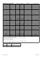
1
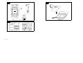
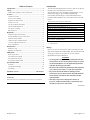
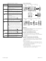
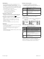
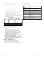
GE
Sensing
Druck DPI 820
Dual input thermometer
User manual - K0386
Customer service
A1
B1
10
10
10a
9a
1
9
A2
8
2
7
3
6
11
4
5
B1
12
A2
16
15
14
13
22
17
18
21
19
20
K0386 Issue 2
Visit our web site: www.gesensing.com
Table of Contents
Introduction ......................................................................... 1
Safety ..................................................................................... 1
Marks and symbols on the instrument ................................. 2
To start .................................................................................. 2
Location of items ............................................................................ 2
Items on the display ...................................................................... 2
Prepare the instrument ................................................................ 2
Power on or off ................................................................................ 2
Set up the basic operation ......................................................... 3
Select a task (Measure) ................................................................ 3
Set up the settings ......................................................................... 3
Edit functions .................................................................................... 4
Operation .............................................................................. 4
Thermocouple connections ....................................................... 4
Communications port connections ........................................ 4
Measure temperature .................................................................. 5
UPM Pressure measurements .................................................. 5
Use the Snapshot functions ....................................................... 6
Error indications .............................................................................. 7
Maintenance ........................................................................ 8
Clean the unit ................................................................................... 8
Replace the batteries .................................................................... 8
Calibration ............................................................................ 8
Before you start ............................................................................... 8
Procedures (mV input) .................................................................. 9
Procedures (CJ input) .................................................................... 9
Procedures (IDOS UMM) ............................................................... 9
Specification data ............................................................... 9
General ................................................................................................ 9
Temperature ranges .................................................................. 10
mV range ......................................................................................... 10
Customer service ............................................... Back cover
© 2007 General Electric Company. All rights reserved.
Trademarks
All product names are trademarks of their respective companies.
Introduction
The DPI 820 Dual Input Thermometer is part of the Druck
DPI 800 series of hand held instruments.
The DPI 800 series uses Intelligent Digital Output Sensor
(IDOS) technology to give instant plug and play
functionality with a range of Universal Measurement
Modules (UMM). Example: the Universal Pressure Module
(UPM).
The DPI 820 includes these functions:
Function
* Measure temperature: T1 and/or T2
* Measure temperature difference: T1 - T2
* Cold Junction (CJ) compensation: Automatic/Manual
Snapshot: Up to 1000 displays with a date/time stamp
Communications port: IDOS or RS232
Language selection
** Measure pressure/Leak test: External IDOS UPM
Other functions: Hold, Maximum/Minimum/Average, Filter, Tare,
Scaled values, Backlight, Alarm
*
**
Refer to “Specification data”.
Optional item
Safety
Before you use the instrument, make sure that you read
and understand all the related data. This includes: all local
safety procedures, the instructions for the UMM (if
applicable), and this publication.
WARNING
• It is dangerous to ignore the specified limits for the
instrument or to use the instrument when it is not in
its normal condition. Use the applicable protection
and obey all safety precautions.
• Do not use the instrument in locations with explosive
gas, vapor or dust. There is a risk of an explosion.
• To prevent electrical shocks or damage to the
instrument, do not connect more than 30V between
the terminals, or between the terminals and the
ground (earth).
• UPM only. To prevent a dangerous release of
pressure, isolate and bleed the system before you
disconnect a pressure connection.
Continued
K0386 Issue 2
[EN] English - 1
Safety (Continued)
To start - Items on the display A2
Before you start an operation or procedure in this
publication, make sure that you have the necessary skills
(if necessary, with qualifications from an approved training
establishment). Follow good engineering practice at all
times.
Safety - Marks and symbols on the instrument
Complies with European
Union directives
Warning - refer to the
manual
Read the manual
Battery
Ground (Earth)
ON/OFF
Do not dispose of this product as household waste. Refer to
“Maintenance”.
Item
13.
Refer to: Select Task (Table 2)
14.
15.
16.
The measured value satisfies one of the alarm
conditions. Refer to: Settings (Table 3)
The data on the display is on hold. To continue, press
the HOLD button again.
The Snapshot function is set up to record the data on
the display (Keypress or Periodic).
Refer to “Operation” (Table 4)
17.
Shows the battery level: 0 ... 100%.
18.
Identifies the type of data: measurement range, units,
thermocouple type (K, J, T ... ), T1/T2 - If applicable.
= Input
= IDOS Input
T1/T2 Identifies the thermocouple connector
19.
To start
Description
UPM only. Task indication for the leak test.
Refer to: Select Task (Table 2)
Shows the settings applied to the input (If applicable).
123ABC = x:y scaled value
To start - Location of items A1
Item
1.
2.
❍
■■
3.
ESC
4.
5.
6.
7.
8.
9.
9a.
10.
10a.
11.
12.
▲
▼
Description
On or off button.
Left-hand soft-key. Selects the function above it on
the display (Item 20). Example: Edit
Moves back one menu level.
Leaves a menu option.
Cancels the changes to a value.
Increases or decreases a value.
Highlights a different item.
Holds the data on the display. To continue, press the
HOLD button again.
If Snapshot is on (Item 16): HOLD records the data on
the display.
Shows the Select Task menu.
MENU
Selects or accepts an item or value.
OK
Selects [✓] or cancels [ ] a selection.
HOLD
■■
SENSOR
/ PC
Right-hand soft-key. Selects the function above it on
the display (Item 20). Example: Settings
Display. Refer to A2
Communications port. Use to connect a Universal
Measurement Module (UMM) or a RS232 cable.
Optional item - Part No. IO800D: RS232 cable (5-pin to
9-pin D type connector). Use to copy the snapshot
records to a PC or to a printer. Refer to “Operation”.
Thermocouple connector: Refer to “Operation”.
Type K thermocouple (two included).
Connection point for some of the optional
accessories. Refer to the datasheet.
Battery compartment. Refer to B1.
2 - [EN] English
= Filter
= Tare
Refer to: Settings (Table 3)
= Maximum
= Average
= Minimum
20.
A soft-key function. To select an available function,
press the soft-key below it. Example:
21.
The measured value or values applicable to the task
selection.
22.
The Edit display to set up text labels ( ≤ 6 characters):
Snapshot (Table 1), x:y Scaling (Table 3).
OK = Accept the new text label
Shift = Change the keys: 123ABC or -_+abc
= Move left
= Move right
= Add a space
BS
= Back space (Delete character)
To start - Prepare the instrument
Before you use the instrument for the first time:
• Make sure that there is no damage to the instrument,
and that there are no missing items.
• Remove the plastic film that protects the display. Use
the tag (◗ ) in the top right-hand corner.
• Install the batteries (refer to B1). Then re-attach the
cover.
To start - Power on or off
To turn the instrument on or off, press ❍ (A1 - item [1]). The
instrument does a self test and then shows the applicable
data.
When the power is off, the last set of configuration options
stays in memory. Refer to “Maintenance”.
K0386 Issue 2
To start - Set up the basic operation
Use the Set Up menu to set up the basic operation of the
instrument.
1
Menu:
Select Task
2
3
Menu:
Set Up
▲
▼
(Table 2)
4
5
1
Menu:
Select Task
▲
▼
(Table 1)
2
3
Display:
T2 input
▲
▼
[✓]/[ ]
If there is additional data for a menu option, select
Settings (■ ■) to see the values that are set up. If
necessary, adjust the values.
Table 1: Menu options - Set Up
Options
(If applicable)
To start - Select a task (Measure)
When the instrument is set up (Table 1), use the Select Task
menu to select the applicable task.
(Table 2)
Table 2: Menu options - Select Task
Description
To set up and use the Snapshot functions.
Additional data: Refer to “Operation” (Table 4)
... Scale To select the applicable international temperature
scale: IPTS 68 or ITS 90.
CJ ... To select the type of cold junction (CJ)
compensation.
Automatic: The instrument monitors the CJ
temperature and applies the necessary CJ
compensation.
Manual: Measure the CJ temperature and set the
applicable value. The instrument uses this value to
apply the necessary CJ compensation.
Additional data (Manual): Select Settings (■ ■)
To select and set up the backlight facility + timer.
Additional data: Select Settings (■ ■)
To select and set up the power off facility + timer.
Additional data: Select Settings (■ ■)
To show the battery level (%).
To set the display contrast (%).
▲ Increases %, ▼ decreases %
To set the time + date. The calibration facility uses
the date to give service and calibration messages.
Snapshot adds a date/time stamp to each display.
To set the language option.
To calibrate the instrument.
Additional data: Refer to “Calibration”.
To select and show the applicable status data.
(Software Build, Calibration Due date, Serial
Number, IDOS Information).
Sk2 = Settings
In Table 2, IDOS is a Universal Measurement Module
(UMM). If you attach a UMM to the communications port
(A1 - item [9]), the Select Task menu shows the applicable
IDOS options.
Options
(If applicable)
Description
T1
Selects one temperature measurement task (T1, T2,
T1-T2). T1-T2 gives the temperature difference.
Selects two temperature measurement tasks (T1
and T2).
IDOS
UMM only. An IDOS measurement task.
UMM only. Selects one temperature measurement
task (T1, T2, T1-T2) + an IDOS measurement task.
UPM only. Selects the IDOS pressure measurement
task + leak test.
IDOS
To set up the way the instrument works.
Additional data: Refer to: Set Up (Table 1).
To start - Set up the settings
When the task is set up (Table 2), use the Settings menu to
adjust the measurement operation.
Display: Task
T1, T2
1
Settings selection
(If applicable)
2
3
▲
▼
■■
Sk2 = Settings
Menu:
Settings
4
5
▲
▼
(Table 3)
6
Settings
x:y
■■
[✓]/[ ]
Sk1 = Edit
If there is additional data for a menu option, select
Settings (■ ■) to see the values that are set up. If
necessary, adjust the values. Refer to “Edit functions”.
K0386 Issue 2
[EN] English - 3
Table 3: Menu options - Settings
Options
Description
(If applicable)
... Units To select the temperature units (°C or °F).
UPM only = “Pressure Units” if you select an IDOS
task (Table 2). Select one of the fixed units of
measurement (psi, mbar ... ).
... type To select an applicable thermocouple
type (K, J, T ... )
To include maximum, minimum and average
values for the measurement task. Only available
when there is one input measurement task.
To select and set up a tare value for the
measurement task (a specified value or the reading
on the display).
The instrument subtracts a positive tare value, and
adds a negative tare value.
Additional data: Select Settings (■ ■)
To select and set up a scale of values: One local
scale for each measurement task (Maximum: 5).
Additional data (Example 1/2): Select Settings (■ ■)
To start - Edit functions
Example 1) Set up a label for x:y Scaling = %.
Settings
x:y
To select and set up the alarm values for the
measurement task (maximum and minimum).
Additional data: Select Settings (■ ■)
UPM only. Gage sensors or sensors with differential
operation. A zero correction that makes the
instrument read zero at local pressure.
Leak Test only. To set an applicable period for the
leak test (Hours:Minutes:Seconds).
4 - [EN] English
Edit
■■
Sk1 = Edit
2
Edit
▲
▼
■■
Shift
3
A2 - item [22]
Edit
...
Edit
4
5
%_
OK
▲
▼
■■
A2 - item [22]
Example 2) Set up values for x:y Scaling = 0 to 100%.
Settings
x:y
To select and set up the filter values to give a
smoother output for the measurement task:
Band as a % of full scale (FS). The filter
compares each new value with the previous
value. If the new value is outside the band, it is not
filtered.
Low pass filter time constant in seconds.
Increase the value to increase damping
factor.
Additional data: Select Settings (■ ■)
1
1
▲
▼
Settings
x:y
2
■■
Edit
3
4
▲
▼
■■
Sk1 = Edit
Operation
This section gives examples of how to connect and use the
instrument. Before you start:
• Read and understand the “Safety” section.
• Do not use a damaged instrument.
Operation - Thermocouple connections
Attach the thermocouple wires to the applicable
thermocouple mini-connector (Figure 1). The wider blade is
the negative.
Then attach the connector to the instrument.
Operation - Communications port connections
Use the communications port (A1 - item [9]) to attach an
IDOS Universal Measurement Module (UMM) or an RS232
device.
IDOS Communications
When you attach the cable from a UMM (Figure 3/4), the
instrument automatically changes the menus to give you
all the applicable options (Table 2).
RS232 Communications
Use an RS232 cable (A1 - item [9a]) to transmit all the
Snapshot data to a PC or a printer (Table 4).
K0386 Issue 2
Operation - Measure temperature
To measure temperature:
1. Connect the applicable thermocouples (Figure 1/2)
and, if necessary, adjust the Set Up (Table 1).
2. Select a Temperature input task from Select Task
(Table 2) and, if necessary, adjust the Settings (Table 3).
T1
K
K
T2
T1
K
T2
K
T1
T2
Reference
T1
T2
T1
T2
Settings
a) T1 - T2
Figure 2: Example configuration - To measure the
temperature difference
Operation - UPM Pressure measurements
Read all the instructions supplied with the UPM and then
use the specified procedures to connect it (Figure 3/4).
Settings
a) T1 or T2
Settings
b) T1 and T2
Figure 1: Example configurations - To measure the
temperature with one or two thermocouples
The examples in Figure 1 show how to compare
temperatures or measure different temperatures in a
system.
Settings
a) Pressure
Start
Settings
b) Leak test
Figure 3: Example configuration - Pressure measurement
with a UPM
K0386 Issue 2
[EN] English - 5
When the connections are complete, make the necessary
IDOS selections (Table 2).
If you re-attach a UPM, the instrument uses the same
measurement units that you used before. The instrument
keeps a record for the last 10 modules.
UPM - Measure the pressure
To measure the pressure (Figure 3):
Operation - Use the Snapshot functions
Use Snapshot to record up to 1000 displays then examine
the results on the display, or transmit all the data to a PC
or printer (Figure 5).
Menu:
Set Up
To measure pressure with another operation (Figure 4), use
the same procedure.
T1
2
Menu:
Snapshot
▲
▼
1. Select the applicable pressure task from Select Task
(Table 2) and, if necessary, adjust the Set Up (Table 1),
and the Settings (Table 3).
2. If necessary, do a zero correction (Table 3).
1
(Table 1)
3
4
▲
▼
(Table 4)
If there is additional data for a menu option, select
Settings (■ ■) to see the values that are set up. If
necessary, adjust the values.
Table 4: Snapshot functions
Options
K
Description
Use Snapshot Setup to set up a tag name for the
Snapshot file (refer to “To start - Edit functions”) and
to select the Snapshot method.
Keypress: Use this option to record an
individual display each time you press HOLD.
Periodic: Use this option to record the displays
at specified intervals of time. Press HOLD to
start.
Additional data: Select Settings (■ ■)
Off - Snapshot is off
To show the available Snapshot data on the display.
Use these keys:
▲, ▼, MENU/OK
To transmit all the Snapshot data to a PC or a
printer (Figure 5).
To erase all the Snapshot data.
Settings
Figure 4: Example configuration - To measure pressure
and temperature
UPM - Leak test
To do a leak test on a pressure system (Figure 3):
1. Select an applicable leak test from Select Task (Table 2)
and, if necessary, adjust the Set Up (Table 1), and the
Settings (Table 3).
To show the amount of memory used (%).
Total memory = 12 288 bytes
Capacity ≈ 1000 displays (one measurement)
Capacity ≈ 750 displays (two measurements)
Example:
One file ≈ 96 bytes (no Settings)
For each display in the file:
Date/Time = 8 bytes; Each value = 4 bytes
One display (One measurement) = 12 bytes
2. Set the period for the leak test (Table 3).
3. If necessary, do a zero correction (Table 3).
4. To start the leak test, select Start (■ ■). When the test is
finished, the instrument calculates the leak rate in the
applicable units/minute.
6 - [EN] English
K0386 Issue 2
Snapshot - Use the Snapshot data
Use HOLD to record the data (Table 4). When you have
sufficient records, select Stop Log (■ ■). You can then read
the data back on the display or transmit it to a PC or
printer.
Step
Procedure
➀, ➁
A1 - Item 1b (Optional): Connect the 5-pin
connector to the IDOS instrument.
A1 - Item 1b (Optional): Connect the 9-pin
connector to the serial port on the PC or to a serial
printer (refer to the PC or printer instructions).
PC: Make sure that Windows® HyperTerminal or
similar program is set up to use the specified data
format (refer to your PC on-line Help).
Serial printer: Make sure that the printer can use
the specified data format.
Data format
➂
➃
Snapshot - Contents of the Snapshot data
Model
Serial No
820
8200000001
Calibration
due
Tag
01/01/2004
H2O-1
Task Id
110
(English text only)
T1 in
Date
Time
°C K T1
08/07/2004
08/07/2004
Tag
12:06:44
12:06:46
B145
27.6
27.2
Task Id
T1 In
T2 In
164
Tare On
Filter On
Tare On
Date
08/07/2004
Time
14:41:36
°C K T1
32.5
°C K T2
32.4
08/07/2004
08/07/2004
14:41:38
14:41:41
32.5
32.4
32.4
32.5
Figure 6: Example Snapshot data
Operation - Error indications
If the display shows <<<< or >>>> :
• Make sure that the range is correct.
• Make sure that all the related equipment and
connections are serviceable.
Baud rate: 19200
Data bits: 8
Parity: None
Stop bits: 1
Software handshake: Xon/Xoff Flow Control.
ASCII format text; Comma delimited
ASCII Setup: Make sure that the ASCII Receiving
option is set to “Append line feeds to incoming line
ends”
➄
Transmit the data to the PC or printer (Table 4).
PC: Use Windows® HyperTerminal or a similar
program to make a text file. You can then import
the text file into a spreadsheet.
Figure 5: Procedure to transmit the Snapshot data
K0386 Issue 2
[EN] English - 7
Maintenance
This section gives procedures to maintain the unit in a
good condition. Return the instrument to the
manufacturer or an approved service agent for all repairs.
Do not dispose of this product as household waste. Use an
approved organisation that collects and/or recycles waste
electrical and electronic equipment.
For more information, contact one of these:
• our customer service department:
(Contact us at www.gesensing.com)
• your local government office.
Maintenance - Clean the unit
Clean the case with a moist, lint-free cloth and a weak
detergent. Do not use solvents or abrasive materials.
Maintenance - Replace the batteries B1
To replace the batteries, refer to B1. Then re-attach the
cover.
Make sure that the time and date are correct. The
calibration facility uses the date to give service and
calibration messages.
All the other configuration options stay in memory.
Calibration - Before you start
To do an accurate calibration, you must have:
• the calibration equipment specified in Table 5.
• a stable temperature environment: 70 ± 2°F (21 ± 1°C)
Table 5: Calibration equipment
Function
mV
CJ
Pressure
Calibration equipment
mV calibrator.
Accuracy: Refer to Table 7.
- Standard RTD probe
Accuracy: 50 mK for 23 … 82.4°F (-5 … 28°C)
- Digital thermometer
Accuracy: 10 mK
UPM only. Refer to the user manual for the IDOS
UPM.
Before you start the calibration, make sure that the time
and date on the instrument are correct (Table 1).
Selection sequence:
➤ Select Task (Table 2) ➤ Set Up (Table 1) ➤ Calibration ➤
1
Display: Enter
Calibration PIN
We recommend that you return the instrument to the
manufacturer or an approved service agent for
calibration.
If you use an alternative calibration facility, make sure that
it uses these standards.
3
Menu:
Select Channel
▲
▼
+
■■
Calibration
Note: GE can provide a calibration service that is traceable
to international standards.
2
Factory PIN = 4321
4
5
▲
▼
(Table 6)
Table 6: Calibration options
Options
mV ...
CJ ...
IDOS ...
Description
To calibrate the specified thermocouple channel.
To calibrate the specified cold junction channel.
UMM only. To calibrate the specified IDOS UMM.
Refer to the user manual for the IDOS UMM.
Calibration Due: To set the date of the next
calibration for the instrument.
After the specified calibration date, there is a
warning message. There is a selection box to stop
the warning.
To change the calibration PIN (Personal
Identification Number).
When you select a channel, the display shows the
applicable instructions to complete the calibration.
When the calibration is complete, select Calibration Due
and set the new calibration date for the instrument.
8 - [EN] English
K0386 Issue 2
Specification data
Calibration - Procedures (mV input)
1. Connect the instrument to the calibration equipment:
mV input = Figure 1
2. Let the equipment get to a stable temperature
(minimum: 5 minutes since the last power on).
3. Use the calibration menu (Table 6) to do the calibration:
mV input = three-point calibration (-FS, Zero and +FS).
Note: mV range = -10 ... 100 mV
4. To make sure that the calibration is correct, set up an
applicable T1/T2 input task (Figure 1).
5. Apply a range of mV values that are applicable to the
specified thermocouple (Table 7).
6. Make sure that the error is in the specified limits: use
the applicable values from Table 7 and the reference
table for the thermocouple.
Table 7: mV input error limits
Input
(mV)
±5
0
10
20
50
75
Calibrator error
(mV)
mV
0.0004
0.0005
0.0006
0.0008
0.0010
Permitted DPI 820 error
(mV)
mV
0.009
0.008
0.010
0.011
0.016
0.018
All accuracy statements are for one year.
Specification - General
Languages
Operating
temperature
English [Default]
14 … 122°F (-10 … 50°C)
Storage
temperature
-4 … 158°F (-20 … 70°C)
Humidity
0 to 90% without condensation
(Def Stan 66-31, 8.6 cat III)
BS EN 61010:2001; Def Stan 66-31, 8.4 cat III
BS EN 61326-1:1998 + A2:2001
Shock/Vibration
EMC
Safety
Size (L: W: H)
Electrical - BS EN 61010:2001; CE Marked
7.1 x 3.3 x 2.0 in
(180 x 85 x 50 mm)
Weight
Power supply
Duration
(Measure)
14 oz (400 g)
3 x AA alkaline batteries
T1, T2: ≈ 70 hours
Calibration - Procedures (CJ input)
1. Connect the instrument to the calibration equipment
(Figure 1).
2. Let the equipment get to a stable temperature
(minimum: 5 minutes since the last power on).
3. Use the calibration menu (Table 6) to do a one-point
calibration (+FS). The display shows the applicable
instructions to complete the calibration.
4. To make sure that the calibration is correct, select the
applicable T1/T2 input task (Table 2).
5. Make sure that the DPI 820 gives a probe temperature
that agrees with the temperature on the digital
thermometer ±0.2°F (0.1°C).
Calibration - Procedures (IDOS UMM)
Refer to the user manual for the IDOS UMM.
When the calibration is complete, the instrument
automatically sets a new calibration date in the UMM.
K0386 Issue 2
[EN] English - 9
Specification - Temperature ranges
Thermocouple type
K
K
Standard
IEC 584
IEC 584
Range °F
-454 .... -328
-328 ... 2502
Range °C
-270 .... -200
-200 ... 1372
Accuracy °F *
3.6
1.1
Accuracy °C *
2.0
0.6
J
T
IEC 584
IEC 584
-346 ... 2192
-454 .... -292
-210 ... 1200
-270 .... -180
0.9
2.5
0.5
1.4
T
T
B
IEC 584
IEC 584
IEC 584
-292 ...... -94
-94 ..... 752
122 ..... 932
-180 ...... -70
-70 ..... 400
50 ..... 500
0.9
0.6
9.4
0.5
0.3
5.2
B
B
R
IEC 584
IEC 584
IEC 584
932 ... 2192
2192 ... 3308
-58 ....... 32
500 ... 1200
1200 ... 1820
-50 ......... 0
3.6
2.2
5.4
2.0
1.2
3.0
R
R
IEC 584
IEC 584
32 ..... 572
572 ... 3214
0 ..... 300
300 ... 1768
3.6
1.8
2.0
1.0
S
S
S
IEC 584
IEC 584
IEC 584
-58 ....... 32
32 ..... 212
212 ... 3214
-50 ......... 0
0 ..... 100
100 ... 1768
4.5
3.4
2.5
2.5
1.9
1.4
E
E
IEC 584
IEC 584
-454 .... -238
-238 ... 1832
-270 .... -150
-150 ... 1000
1.6
0.7
0.9
0.4
N
N
L
IEC 584
IEC 584
DIN 43710
-454 ........ -4
-4 ... 2372
-328 ... 1652
-270 ...... -20
-20 ... 1300
-200 ..... 900
1.8
1.1
0.6
1.0
0.6
0.3
U
U
C
DIN 43710
DIN 43710
-328 ..... 212
212 ... 1112
32 ... 2732
-200 ..... 100
100 ..... 600
0 ... 1500
0.9
0.6
1.8
0.5
0.3
1.0
C
C
2732 ... 3632
3632 ... 4208
1500 ... 2000
2000 ... 2320
2.5
3.4
1.4
1.9
D
D
D
32 ... 3092
3092 ... 3992
3992 ... 4514
0 ... 1700
1700 ... 2200
2200 ... 2490
1.8
2.9
6.5
1.0
1.6
3.6
ХА (К) **
ЖК (J) **
МК (Т) **
-454 ... 2502
-346 ... 2192
-454 ..... 752
-270 ... 1372
-210 ... 1200
-270 ..... 400
-
0.6 ***
0.5 ***
0.3 ***
ПР (B) **
ПП (S) **
122 ... 3308
-58 ... 3214
50 ... 1820
-50 ... 1768
-
1.2 ***
1.4 ***
-454 ... 1832
32 ... 4532
-328 ... 1472
-270 ... 1000
0 ... 2500
-200 ..... 800
-
0.4 ***
2.5 ***
0.25 ***
ХК (Е) **
ВР-1 **
ХК(r) / ХК(рус) **
ГОСТ 50431-92
ГОСТ 50431
* Mid-point value for the specified range. To calculate the actual error at a specified temperature, use the mV specification and the
reference table for the applicable thermocouple.
** Only available with Russian versions of the DPI 820. *** Best accuracy for the range.
Cold Junction (CJ) error (Maximum):
Range 50° ... 86°F (10 ... 30°C) = 0.4°F (0.2°C)
Add 0.01° CJ error / ° ambient temperature change for ranges:
14 … 50°F, 86 … 122°F
(-10 … 10°C, 30 … 50°C)
Specification - mV range
Range
(mV)
-10 ... 100
Impedance
Accuracy
< 0.2 Ω
0.02% of reading + 0.01% FS
10 - [EN] English
K0386 Issue 2