1
PRIMECLUSTER Global Disk Services
Configuration and Administration
Guide 4.3
Linux
J2UZ-7243-03ENZ0(01)
May 2013
Preface
This manual describes the setting up and managing of GDS (Global Disk Services) and GDS Snapshot, an optional product of GDS,
discussing the supported functions.
Purpose
This manual aims to help users understand GDS and GDS Snapshot, including environment configuration, operation and maintenance.
Target Reader
This manual is devoted to all users who will operate and manage GDS and GDS Snapshot and programmers who will create applications
running in GDS environments.
Organization
This manual consists as follows:
"YES" in the Operator or Administrator column indicates who would benefit from reading that portion.
Headers
Contents
Operator
Administrator
Chapter 1
Functions
Explains the features of GDS and GDS Snapshot.
YES
YES
Chapter 2
Objects
Explains the objects used by GDS and GDS
Snapshot.
YES
YES
Chapter 3
Starting and Exiting GDS
Management View
Explains how to start and exit GDS Management
and the required browser environment.
YES
YES
Chapter 4
Management View Screen
Elements
Explains the contents of Management View.
YES
YES
Chapter 5
Operation
Explains the details about GDS operation such as
operation flow, settings, maintenance and
management.
YES
YES
Chapter 6
Backing Up and Restoring
Explains how to back up and restore data on disks
managed by GDS.
YES
YES
Appendix A
General Notes
Explains guidelines, general precautions, and
configuration tips necessary for using GDS.
-
YES
Appendix B
Log Viewing with WebBased Admin View
For details, see the supplementary "Web-Based
Admin View Operation Guide."
-
YES
Appendix C
Web-Based Admin View
Operating Environment
Setting
For details, see the supplementary "Web-Based
Admin View Operation Guide."
YES
YES
Appendix D
Command Reference
Explains the commands available in GDS and
GDS Snapshot.
-
YES
Appendix E
GDS Messages
Explains the contents, possible causes, and
resolutions for GDS messages that appear when
setting or operating GDS and GDS Snapshot.
YES
YES
-i-
Headers
Contents
Operator
Administrator
Appendix F
Troubleshooting
Explains resolutions for abnormality of objects
and physical disks managed by GDS.
-
YES
Appendix G
Frequently Asked
Questions (FAQ)
Lists frequently asked questions regarding GDS
and GDS Snapshot.
YES
YES
Appendix H
Shared Disk Unit Resource
Registration
Explains shared disk unit resource registration to
be performed first to use GDS in a cluster system.
YES
YES
Appendix I
Server and Storage
Migration
Explains how to migrate servers and storage to
new units on the system where GDS is used.
YES
YES
Appendix J
Disaster Recovery
Explains how to configure and operate the disaster
recovery system where GDS is used.
YES
YES
Appendix K
Release Information
Explains new features of GDS and GDS Snapshot,
manual update details, and changes in
specifications depending on the versions.
YES
YES
Glossary
Explains GDS and GDS Snapshot terminology.
Please refer to it as necessary.
YES
YES
Related documentation
Please refer to the following documents according to need.
- PRIMECLUSTER Concepts Guide
- PRIMECLUSTER Installation and Administration Guide
- PRIMECLUSTER Cluster Foundation (CF) Configuration and Administration Guide
- PRIMECLUSTER Reliant Monitor Services (RMS) with Wizard Tools Configuration and Administration Guide
- PRIMECLUSTER Web-Based Admin View Operation Guide
- PRIMECLUSTER Global File Services Configuration and Administration Guide
- Software Release Guide PRIMECLUSTER(TM) GDS
- PRIMECLUSTER GDS Installation Guide
- Software Release Guide PRIMECLUSTER(TM) GDS Snapshot
- INSTALLATION GUIDE PRIMECLUSTER(TM) GDS Snapshot
- PRIMEQUEST Virtual Machine Function User's Manual
Manual Printing
Use the PDF file supplied in the product CD-ROM to print this manual.
Adobe Reader is required to read and print this PDF file. To get Adobe Reader, see Adobe Systems Incorporated's website.
Symbol
The following conventions are used in this manual:
- [1 TB] indicates that the description is for environments (include the case that the configuration parameter SDX_EFI_DISK=on is
not set) which support 1 TB or larger disks.
- ii -
- [4.3A00] indicates that the description is for GDS 4.3A00.
- [4.3A10 or later] indicates that the description is for GDS 4.3A10 or later.
- [Linux2.4] indicates that the description is for Linux kernel version 2.4.
- [Linux2.6] indicates that the description is for Linux kernel version 2.6.
- [PRIMEQUEST] indicates that the description is for the PRIMEQUEST server platform.
- [RHEL6] indicates that the description is for RHEL6.
Point
Main points are explained.
Note
Items that require attention are explained.
Information
Useful information is given.
See
Manual names and sections of this manual you should refer to are given.
Abbreviated name
- Device Mapper Multipath is abbreviated as DM-MP.
- ETERNUS SF AdvancedCopy Manager is abbreviated as ACM.
- Itanium Processor Family is abbreviated as IPF.
- Red Hat Enterprise Linux is abbreviated as RHEL.
- Red Hat Enterprise Linux AS is abbreviated as RHEL-AS.
- Red Hat Enterprise Linux ES is abbreviated as RHEL-ES.
Date of publication and edition
June 2011, First edition
August 2012, 1.1 edition
December 2012, Second edition
May 2013, 2.1 edition
Trademarks
Microsoft, Windows, Windows NT, Windows Me, Internet Explorer, and Windows 2000 are registered trademarks of Microsoft
Corporation in the United States and other countries.
- iii -
Linux is a registered trademark of Linus Torvalds.
Red Hat is a registered trademark of Red Hat, Inc. in the U.S. and other countries.
Oracle and Java are registered trademarks of Oracle and/or its affiliates. Other names may be trademarks of their respective owners.
EMC, PowerPath, SRDF, Symmetrix, and TimeFinder are registered trademarks of EMC Corporation.
SAN Manager is a trademark of EMC Corporation.
PRIMECLUSTER is a trademark of Fujitsu LIMITED.
Other product names that appear in this manual are product names, trademarks, or registered trademarks of respective companies.
Notice
- No part of this manual may be reproduced without permission.
- This manual is subject to change without advance notice.
All Rights Reserved, Copyright (C) FUJITSU LIMITED 2011-2013.
Editing Record
Additions and changes
Section
Changed the required patch numbers for RHEL6.
A.2.42 DM-MP (Device Mapper Multipath)
Changed the required patch number when using 1 TB or larger
disks in GDS 4.3A10.
A.2.6 Disk Size
E.4.1 Error Messages (60000-60399)
Changed the description of a device name in the shared disk
definition file.
A.2.42 DM-MP (Device Mapper Multipath)
H.4 Shared Disk Unit Resource Registration
Procedure
Added the following messages:
E.3.3 Warning Messages (44000-44099)
- 44039
- 44040
Modified the procedure for PRIMEQUEST 1000 series
described in "Resolution" in "(4) System cannot be booted.
(Failure of all boot disks)."
F.1.5 System Disk Abnormality
[PRIMEQUEST]
- iv -
Edition
2.1
Contents
Chapter 1 Functions.................................................................................................................................................................1
1.1 GDS Features.......................................................................................................................................................................................1
1.2 Functions for High Availability...........................................................................................................................................................2
1.2.1 Disk Mirroring..............................................................................................................................................................................3
1.2.1.1 System Disk Mirroring [PRIMEQUEST]..............................................................................................................................3
1.2.1.2 Mirroring between Disk Array Unit......................................................................................................................................4
1.2.1.3 Shared Disk Mirroring...........................................................................................................................................................5
1.2.2 Hot Spare......................................................................................................................................................................................6
1.2.3 Hot Swap.......................................................................................................................................................................................8
1.2.4 Just Resynchronization Mechanism (JRM)..................................................................................................................................9
1.3 Functions for High Manageability.....................................................................................................................................................10
1.3.1 Operation Management Interface...............................................................................................................................................11
1.3.2 Centralized Disk Management....................................................................................................................................................11
1.3.3 Name Management.....................................................................................................................................................................12
1.3.4 Single System Image Environment.............................................................................................................................................13
1.3.5 Access Control............................................................................................................................................................................14
1.3.6 Realizing Large Capacity and I/O Load Balancing....................................................................................................................16
1.3.6.1 Logical Partitioning.............................................................................................................................................................16
1.3.6.2 Disk Concatenation..............................................................................................................................................................16
1.3.6.3 Disk Striping........................................................................................................................................................................17
1.3.6.4 Combining Disk Striping with Mirroring............................................................................................................................18
1.3.7 Online Volume Expansion..........................................................................................................................................................18
1.3.8 Snapshots by Slice Detachment..................................................................................................................................................20
1.4 GDS Snapshot Features.....................................................................................................................................................................22
1.5 Proxy Volume....................................................................................................................................................................................22
1.5.1 Snapshot by Synchronization......................................................................................................................................................24
1.5.2 Snapshot Function with No Load to the Server/SAN.................................................................................................................28
1.5.3 Instant Snapshot by OPC............................................................................................................................................................29
1.5.4 Instant Restore............................................................................................................................................................................30
1.5.5 Online Disk Migration................................................................................................................................................................32
1.5.6 Creating an Alternative Boot Environment [PRIMEQUEST]...................................................................................................33
1.6 Shadow Volume.................................................................................................................................................................................34
1.6.1 Accessing Volumes from an External Server.............................................................................................................................34
1.6.2 Using the Copy Function of a Disk Unit....................................................................................................................................35
Chapter 2 Objects...................................................................................................................................................................37
2.1 SDX Object........................................................................................................................................................................................37
2.1.1 Disk Class...................................................................................................................................................................................37
2.1.2 SDX Disk....................................................................................................................................................................................40
2.1.3 Disk Group..................................................................................................................................................................................43
2.1.4 Logical Volume..........................................................................................................................................................................45
2.1.5 Logical Slice...............................................................................................................................................................................50
2.2 GDS Snapshot Objects.......................................................................................................................................................................54
2.2.1 Proxy Object...............................................................................................................................................................................54
2.2.2 Shadow Object............................................................................................................................................................................58
2.2.2.1 Shadow Class.......................................................................................................................................................................59
2.2.2.2 Shadow Disk........................................................................................................................................................................61
2.2.2.3 Shadow Group.....................................................................................................................................................................64
2.2.2.4 Shadow Volume...................................................................................................................................................................65
2.2.2.5 Shadow Slice........................................................................................................................................................................71
Chapter 3 Starting and Exiting GDS Management View........................................................................................................72
3.1 Preparation for Starting GDS Management View.............................................................................................................................72
3.1.1 Deciding the User Group............................................................................................................................................................72
3.1.1.1 User Group Types................................................................................................................................................................72
-v-
3.1.1.2 Creating User Groups..........................................................................................................................................................72
3.1.1.3 Registering to a User Group................................................................................................................................................72
3.1.2 Setting up the Client Environment..............................................................................................................................................73
3.1.3 Setting up the Web Environment................................................................................................................................................73
3.2 Starting the GDS Management View................................................................................................................................................73
3.2.1 Starting Web-Based Admin View Operation Menu...................................................................................................................73
3.2.2 Web-Based Admin View Operation Menu Functions................................................................................................................74
3.2.3 Starting GDS Management View...............................................................................................................................................75
3.3 Exiting GDS Management View.......................................................................................................................................................76
3.4 Changing the Web-Based Admin View Settings...............................................................................................................................77
Chapter 4 Management View Screen Elements.....................................................................................................................78
4.1 Screen Configuration.........................................................................................................................................................................78
4.2 Menu Configuration and Functions...................................................................................................................................................81
4.2.1 General........................................................................................................................................................................................81
4.2.2 Settings........................................................................................................................................................................................82
4.2.3 Operation....................................................................................................................................................................................89
4.2.4 View............................................................................................................................................................................................91
4.2.5 Help.............................................................................................................................................................................................92
4.3 Icon Types and Object Status............................................................................................................................................................92
4.4 Object Information.............................................................................................................................................................................96
Chapter 5 Operation...............................................................................................................................................................98
5.1 Operation Outline..............................................................................................................................................................................98
5.1.1 System Disk Settings [PRIMEQUEST].....................................................................................................................................98
5.1.2 Configuration Settings................................................................................................................................................................99
5.1.2.1 Single Volume Configuration Settings................................................................................................................................99
5.1.2.2 Other Volume Configuration Settings.................................................................................................................................99
5.1.3 Backup......................................................................................................................................................................................100
5.1.3.1 Backup (by Slice Detachment)..........................................................................................................................................100
5.1.3.2 Backup (by Synchronization)............................................................................................................................................101
5.1.3.3 Backup (by OPC)...............................................................................................................................................................103
5.1.4 Restore......................................................................................................................................................................................103
5.1.5 Disk Swap.................................................................................................................................................................................104
5.1.6 Disk Migration..........................................................................................................................................................................105
5.1.7 Configuration Change...............................................................................................................................................................105
5.1.8 Unmirroring the System Disk [PRIMEQUEST]......................................................................................................................106
5.1.9 Operations from GDS Management View................................................................................................................................107
5.2 Settings.............................................................................................................................................................................................110
5.2.1 System Disk Settings [PRIMEQUEST]...................................................................................................................................110
5.2.2 Operating from the Settings Menu............................................................................................................................................117
5.2.2.1 Class Configuration...........................................................................................................................................................117
5.2.2.2 Cluster System Class Configuration..................................................................................................................................120
5.2.2.3 Group Configuration..........................................................................................................................................................122
5.2.2.4 Volume Configuration.......................................................................................................................................................124
5.2.3 File System Configuration........................................................................................................................................................128
5.2.4 Proxy Configuration.................................................................................................................................................................130
5.2.4.1 Join.....................................................................................................................................................................................130
5.2.4.2 Relate.................................................................................................................................................................................135
5.3 Operation in Use..............................................................................................................................................................................138
5.3.1 Viewing Configurations/Statuses and Monitoring Statuses.....................................................................................................138
5.3.1.1 Confirming SDX Object Configuration.............................................................................................................................138
5.3.1.2 Viewing Proxy Object Configurations..............................................................................................................................144
5.3.1.3 Monitoring Object Status...................................................................................................................................................149
5.3.1.4 Viewing Object Statuses....................................................................................................................................................151
5.3.2 Backup......................................................................................................................................................................................152
5.3.2.1 Backup (by Slice Detachment)..........................................................................................................................................152
5.3.2.2 Backup (by Synchronization)............................................................................................................................................157
- vi -
5.3.2.3 Backup (by OPC)...............................................................................................................................................................163
5.3.3 Restore......................................................................................................................................................................................166
5.3.4 Disk Swap.................................................................................................................................................................................170
5.3.5 Disk Migration..........................................................................................................................................................................175
5.3.6 Copying Operation....................................................................................................................................................................177
5.4 Changes............................................................................................................................................................................................181
5.4.1 Class Configuration..................................................................................................................................................................181
5.4.2 Group Configuration.................................................................................................................................................................186
5.4.3 Volume Configuration..............................................................................................................................................................189
5.5 Removals.........................................................................................................................................................................................190
5.5.1 Removing a File System...........................................................................................................................................................191
5.5.2 Removing a Volume.................................................................................................................................................................192
5.5.3 Removing a Group....................................................................................................................................................................193
5.5.4 Removing a Class.....................................................................................................................................................................194
5.5.5 Unmirroring the System Disk [PRIMEQUEST]......................................................................................................................195
5.5.6 Breaking a Proxy......................................................................................................................................................................198
Chapter 6 Backing Up and Restoring................................................................................................................................... 200
6.1 Backing Up and Restoring a System Disk [PRIMEQUEST]..........................................................................................................200
6.1.1 Checking Physical Disk Information and Slice Numbers........................................................................................................200
6.1.2 Backing Up...............................................................................................................................................................................204
6.1.3 Restoring (When the System Can Be Booted)..........................................................................................................................207
6.1.4 Restoring (When the System Cannot Be Booted)....................................................................................................................210
6.2 Backing Up and Restoring a System Disk through an Alternative Boot Environment [PRIMEQUEST]......................................213
6.2.1 System Configuration...............................................................................................................................................................213
6.2.2 Summary of Backup.................................................................................................................................................................214
6.2.3 Summary of Restore.................................................................................................................................................................215
6.2.4 Summary of Procedure.............................................................................................................................................................216
6.2.5 Configuring an Environment....................................................................................................................................................216
6.2.6 Backing Up...............................................................................................................................................................................219
6.2.7 Restoring...................................................................................................................................................................................222
6.3 Backing Up and Restoring Local Disks and Shared Disks..............................................................................................................227
6.3.1 Offline Backup..........................................................................................................................................................................227
6.3.2 Online Backup (by Slice Detachment).....................................................................................................................................228
6.3.3 Restoring...................................................................................................................................................................................229
6.4 Online Backup and Instant Restore through Proxy Volume............................................................................................................230
6.4.1 Online Backup (by Synchronization).......................................................................................................................................232
6.4.2 Online Backup (Snapshot by OPC)..........................................................................................................................................236
6.4.3 Instant Restore..........................................................................................................................................................................240
6.5 Backing Up and Restoring through Disk Unit's Copy Functions....................................................................................................244
6.5.1 Configuring an Environment....................................................................................................................................................244
6.5.2 Backing Up...............................................................................................................................................................................245
6.5.3 Restoring from Backup Disks...................................................................................................................................................248
6.6 Backing Up and Restoring through an External Server...................................................................................................................250
6.6.1 Backing Up and Restoring a Logical Volume with No Replication.........................................................................................252
6.6.1.1 System Configuration........................................................................................................................................................253
6.6.1.2 Summary of Backup..........................................................................................................................................................253
6.6.1.3 Summary of Restore..........................................................................................................................................................254
6.6.1.4 Summary of Procedure......................................................................................................................................................256
6.6.1.5 Configuring an Environment.............................................................................................................................................256
6.6.1.6 Backing Up........................................................................................................................................................................257
6.6.1.7 Restoring............................................................................................................................................................................261
6.6.2 Backing Up and Restoring through Snapshot by Slice Detachment........................................................................................266
6.6.2.1 System Configuration........................................................................................................................................................266
6.6.2.2 Summary of Backup..........................................................................................................................................................267
6.6.2.3 Summary of Restore..........................................................................................................................................................268
6.6.2.4 Summary of Procedure......................................................................................................................................................270
- vii -
6.6.2.5 Configuring an Environment.............................................................................................................................................271
6.6.2.6 Backing Up........................................................................................................................................................................272
6.6.2.7 Restoring............................................................................................................................................................................276
6.6.3 Backing Up and Restoring Using Snapshots from a Proxy Volume........................................................................................281
6.6.3.1 System Configuration........................................................................................................................................................282
6.6.3.2 Summary of Backup..........................................................................................................................................................282
6.6.3.3 Summary of Restore from a Proxy Volume......................................................................................................................284
6.6.3.4 Summary of Restore from Tape.........................................................................................................................................284
6.6.3.5 Summary of Procedure......................................................................................................................................................286
6.6.3.6 Configuring an Environment.............................................................................................................................................287
6.6.3.7 Backing Up........................................................................................................................................................................288
6.6.3.8 Restoring from a Proxy Volume........................................................................................................................................291
6.6.3.9 Restoring from Tape..........................................................................................................................................................293
6.6.4 Backing Up and Restoring by the Disk Unit's Copy Function.................................................................................................296
6.6.4.1 System Configuration........................................................................................................................................................297
6.6.4.2 Summary of Backup..........................................................................................................................................................298
6.6.4.3 Summary of Restore from a BCV......................................................................................................................................300
6.6.4.4 Summary of Restore from Tape.........................................................................................................................................301
6.6.4.5 Summary of Procedure......................................................................................................................................................303
6.6.4.6 Configuring an Environment.............................................................................................................................................304
6.6.4.7 Backing Up........................................................................................................................................................................305
6.6.4.8 Restoring form a BCV.......................................................................................................................................................310
6.6.4.9 Restoring from Tape..........................................................................................................................................................312
6.7 Backing Up and Restoring Object Configurations..........................................................................................................................317
6.7.1 Backing Up...............................................................................................................................................................................317
6.7.2 Restoring...................................................................................................................................................................................318
Appendix A General Notes...................................................................................................................................................320
A.1 Rules...............................................................................................................................................................................................320
A.1.1 Object Name............................................................................................................................................................................320
A.1.2 Number of Classes...................................................................................................................................................................321
A.1.3 Number of Disks......................................................................................................................................................................321
A.1.4 Number of Groups...................................................................................................................................................................322
A.1.5 Number of Volumes.................................................................................................................................................................322
A.1.6 Number of Keep Disks [PRIMEQUEST]................................................................................................................................322
A.1.7 Creating Group Hierarchy........................................................................................................................................................322
A.1.8 Proxy Configuration Preconditions..........................................................................................................................................324
A.1.9 Number of Proxy Volumes......................................................................................................................................................324
A.1.10 Proxy Volume Size................................................................................................................................................................324
A.1.11 Proxy Group Size...................................................................................................................................................................325
A.2 Important Points..............................................................................................................................................................................325
A.2.1 Managing System Disks..........................................................................................................................................................325
A.2.2 Restraining Access to Physical Special File............................................................................................................................325
A.2.3 Booting from a CD-ROM Device............................................................................................................................................326
A.2.4 Initializing Disk.......................................................................................................................................................................326
A.2.5 Disk Label................................................................................................................................................................................327
A.2.6 Disk Size..................................................................................................................................................................................328
A.2.7 Volume Size.............................................................................................................................................................................329
A.2.8 Hot Spare.................................................................................................................................................................................329
A.2.9 System Disk Mirroring [PRIMEQUEST]................................................................................................................................333
A.2.10 Keep Disk [PRIMEQUEST]..................................................................................................................................................336
A.2.11 Creating a Snapshot by Slice Detachment.............................................................................................................................337
A.2.12 The Difference between a Mirror Slice and a Proxy Volume...............................................................................................337
A.2.13 Just Resynchronization Mechanism (JRM)...........................................................................................................................337
A.2.14 Online Volume Expansion.....................................................................................................................................................339
A.2.15 Swapping Physical Disks.......................................................................................................................................................340
A.2.16 Object Operation When Using Proxy....................................................................................................................................341
- viii -
A.2.17 Using the Advanced Copy Function in a Proxy Configuration.............................................................................................342
A.2.18 Instant Snapshot by OPC.......................................................................................................................................................343
A.2.19 To Use EMC Symmetrix.......................................................................................................................................................344
A.2.20 Using EMC TimeFinder or EMC SRDF in a Proxy Configuration.......................................................................................346
A.2.21 Ensuring Consistency of Snapshot Data................................................................................................................................348
A.2.22 Data Consistency at the time of Simultaneous Access..........................................................................................................348
A.2.23 Volume Access Mode............................................................................................................................................................348
A.2.24 Operation in Cluster System..................................................................................................................................................349
A.2.25 Changing Over from Single Nodes to a Cluster System........................................................................................................349
A.2.26 Disk Switch............................................................................................................................................................................350
A.2.27 Shadow Volume.....................................................................................................................................................................350
A.2.28 Backing Up and Restoring Object Configuration (sdxconfig)..............................................................................................353
A.2.29 GDS Management View........................................................................................................................................................353
A.2.30 File System Auto Mount........................................................................................................................................................353
A.2.31 Raw Device Binding..............................................................................................................................................................354
A.2.32 Volume's Block Special File Access Permission...................................................................................................................355
A.2.33 NFS Mount.............................................................................................................................................................................356
A.2.34 Command Execution Time....................................................................................................................................................358
A.2.35 System Reconfiguration.........................................................................................................................................................358
A.2.36 Operating When There is a Disk in DISABLE Status or There is a Class not Displayed with the sdxinfo Command........359
A.2.37 Adding and Removing Disks [4.3A00].................................................................................................................................359
A.2.38 Use of GDS in a Xen Environment........................................................................................................................................359
A.2.39 Use of GDS in a KVM Environment [4.3A10 or later].........................................................................................................359
A.2.40 Use of GDS in a VMware Environment................................................................................................................................361
A.2.41 Excluded Device List.............................................................................................................................................................361
A.2.42 DM-MP (Device Mapper Multipath) ....................................................................................................................................362
A.2.43 Root Class Operation [PRIMEQUEST]................................................................................................................................364
A.3 General Points.................................................................................................................................................................................364
A.3.1 Guidelines for Mirroring..........................................................................................................................................................364
A.3.2 Guidelines for Striping.............................................................................................................................................................365
A.3.3 Guidelines for Concatenation..................................................................................................................................................365
A.3.4 Guidelines for Combining Striping with Mirroring.................................................................................................................366
A.3.5 Guidelines for GDS Operation in the Virtual Environment....................................................................................................366
Appendix B Log Viewing with Web-Based Admin View.......................................................................................................368
Appendix C Web-Based Admin View Operating Environment Setting.................................................................................369
Appendix D Command Reference........................................................................................................................................370
D.1 sdxclass - Class operations..............................................................................................................................................................370
D.2 sdxdisk - Disk operations................................................................................................................................................................371
D.3 sdxgroup - Group operations..........................................................................................................................................................380
D.4 sdxvolume - Volume operations.....................................................................................................................................................384
D.5 sdxslice - Slice operations...............................................................................................................................................................389
D.6 sdxinfo - Display object configuration and status information.......................................................................................................392
D.7 sdxattr - Set objects attributes.........................................................................................................................................................407
D.8 sdxswap - Swap disk.......................................................................................................................................................................414
D.9 sdxfix - Restore a failed object.......................................................................................................................................................416
D.10 sdxcopy - Synchronization copying operation..............................................................................................................................418
D.11 sdxroot - Root file system mirroring definition and cancellation [PRIMEQUEST]....................................................................420
D.12 sdxparam - Configuration parameter operations...........................................................................................................................423
D.13 sdxconfig - Object configuration operations.................................................................................................................................424
D.14 sdxdevinfo - Display device information......................................................................................................................................429
D.15 sdxproxy - Proxy object operations..............................................................................................................................................430
D.16 sdxshadowdisk - Shadow disk operations.....................................................................................................................................440
D.17 sdxshadowgroup - Shadow group operations...............................................................................................................................445
D.18 sdxshadowvolume - Shadow volume operations..........................................................................................................................448
D.19 Volume Creation Using Command...............................................................................................................................................451
- ix -
D.20 Snapshot Creation Using Command.............................................................................................................................................455
D.21 Volume Expansion Using Commands [PRIMEQUEST].............................................................................................................456
D.22 Checking System Disk Settings Using Commands [PRIMEQUEST].........................................................................................463
Appendix E GDS Messages.................................................................................................................................................466
E.1 Web-Based Admin View Messages (0001-0099)...........................................................................................................................466
E.2 Driver Messages..............................................................................................................................................................................466
E.2.1 Warning Messages (22000-22099)..........................................................................................................................................467
E.2.2 Information Messages (24000-24099).....................................................................................................................................472
E.2.3 Internal Error Messages (26000)..............................................................................................................................................475
E.3 Daemon Messages...........................................................................................................................................................................475
E.3.1 Halt Messages (40000-40099)..................................................................................................................................................477
E.3.2 Error Messages (42000-42099)................................................................................................................................................478
E.3.3 Warning Messages (44000-44099)..........................................................................................................................................490
E.3.4 Information Messages (46000-46199).....................................................................................................................................500
E.3.5 Internal Error Messages (48000)..............................................................................................................................................520
E.4 Command Messages........................................................................................................................................................................521
E.4.1 Error Messages (60000-60399)................................................................................................................................................523
E.4.2 Warning Messages (62000-62099)..........................................................................................................................................600
E.4.3 Information Messages (64000-64099).....................................................................................................................................606
E.4.4 Fix Messages (66000)..............................................................................................................................................................620
E.4.5 Internal Error Messages (68000)..............................................................................................................................................620
E.5 Operation Management View Messages.........................................................................................................................................620
E.5.1 Error Messages (5000-5099)....................................................................................................................................................620
E.5.2 Warning Messages (5000,5100-5199).....................................................................................................................................625
E.5.3 Information Messages (5200-5299).........................................................................................................................................635
Appendix F Troubleshooting.................................................................................................................................................645
F.1 Resolving Problems.........................................................................................................................................................................645
F.1.1 Slice Status Abnormality..........................................................................................................................................................645
F.1.2 Disk Status Abnormality..........................................................................................................................................................653
F.1.3 Volume Status Abnormality.....................................................................................................................................................655
F.1.4 Class Status Abnormality.........................................................................................................................................................671
F.1.5 System Disk Abnormality [PRIMEQUEST]............................................................................................................................674
F.1.6 GDS Management View Abnormality.....................................................................................................................................690
F.1.7 Proxy Object Abnormality........................................................................................................................................................694
F.1.8 EMC Symmetrix Abnormality.................................................................................................................................................696
F.1.9 Cluster System Related Error...................................................................................................................................................701
F.1.10 Shadow Object Errors.............................................................................................................................................................706
F.1.11 Disk Unit Error.......................................................................................................................................................................706
F.1.12 OS Messages...........................................................................................................................................................................707
F.2 Collecting Investigation Material....................................................................................................................................................708
F.2.1 Collecting with pclsnap Command...........................................................................................................................................708
F.2.2 Collecting Initial Investigation Material with sdxsnap.sh Script.............................................................................................708
Appendix G Frequently Asked Questions (FAQ)..................................................................................................................710
G.1 Operation Design............................................................................................................................................................................710
G.2 Environment Configuration............................................................................................................................................................713
G.3 Operation.........................................................................................................................................................................................714
Appendix H Shared Disk Unit Resource Registration..........................................................................................................717
H.1 What Is Shared Disk Resource Registration?.................................................................................................................................717
H.2 The Flow of Shared Disk Resource Registration............................................................................................................................717
H.3 Preconditions and Important Points................................................................................................................................................717
H.4 Shared Disk Unit Resource Registration Procedure.......................................................................................................................718
H.5 Command Reference.......................................................................................................................................................................721
H.5.1 clautoconfig(8)-Execute resource registration.........................................................................................................................721
H.5.2 cldelrsc(8)-Delete resource......................................................................................................................................................722
-x-
Appendix I Server and Storage Migration.............................................................................................................................724
I.1 Server Migration...............................................................................................................................................................................724
I.2 Storage Migration.............................................................................................................................................................................725
I.2.1 Using the GDS Snapshot Online Disk Migration......................................................................................................................725
I.2.2 Using the Copy Function of Storage Units and the sdxconfig Command................................................................................727
Appendix J Disaster Recovery.............................................................................................................................................730
J.1 Building a Disaster Recovery System..............................................................................................................................................730
J.2 Switching to a Disaster Recovery System........................................................................................................................................731
J.3 Restoration to the Operation System from a Disaster Recovery System.........................................................................................731
Appendix K Release Information..........................................................................................................................................732
K.1 New Features..................................................................................................................................................................................732
K.1.1 New Features in 4.2A00..........................................................................................................................................................732
K.1.2 New Features in 4.2A30..........................................................................................................................................................733
K.1.3 New Features in 4.3A00..........................................................................................................................................................734
K.1.4 New Features in 4.3A10..........................................................................................................................................................734
K.1.5 New Features in 4.3A20..........................................................................................................................................................734
K.2 Manual Changes..............................................................................................................................................................................734
K.2.1 4.2A00 Manual Changes..........................................................................................................................................................735
K.2.2 4.2A30 Manual Changes..........................................................................................................................................................735
K.2.3 4.3A00 Manual Changes..........................................................................................................................................................737
K.2.4 4.3A10 Manual Changes..........................................................................................................................................................738
K.2.5 4.3A20 Manual Changes..........................................................................................................................................................748
K.3 Specification Changes Other Than New Features..........................................................................................................................750
K.3.1 Specification Changes in 4.1A30.............................................................................................................................................750
K.3.1.1 The sdxproxy Command Option -e delay.........................................................................................................................750
K.3.2 Specification Changes in 4.1A40.............................................................................................................................................751
K.3.2.1 Character (raw) Device Special Files No Longer Supported............................................................................................751
K.3.2.2 Slice Detachment Completion Notification Message Changes........................................................................................751
K.3.2.3 Command Information Message Changes........................................................................................................................752
K.3.2.4 Command Error Message Changes...................................................................................................................................752
K.3.3 Specification Changes in 4.2A30.............................................................................................................................................752
K.3.3.1 RHEL-AS3 / ES3 Support Termination...........................................................................................................................752
K.3.4 Specification Changes in 4.3A00.............................................................................................................................................752
K.3.4.1 Support for Export to NFS Clients....................................................................................................................................752
K.3.4.2 Change of I/O Amount Supported for Simultaneous Processing.....................................................................................753
K.3.5 Specification Changes in 4.3A10.............................................................................................................................................753
K.3.5.1 Disk Label Type of a Disk with the Size smaller than 1 TB............................................................................................753
K.3.6 Specification Changes in 4.3A20.............................................................................................................................................753
K.3.6.1 Disk Label Type of a Disk with the Size smaller than 1 TB............................................................................................753
Glossary...............................................................................................................................................................................754
- xi -
Chapter 1 Functions
This chapter describes the features and functions of GDS (Global Disk Services) and GDS Snapshot.
1.1 GDS Features
GDS is volume management software that improves the availability and manageability of disk-stored data. GDS protects disk data from
hardware failures and operational mistakes and supports the management of disk units.
GDS has closely related functions below:
- To improve availability of disk data
- To improve manageability of disk data
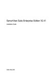
GDS's mirroring function protects data from hardware failures by maintaining replicas of disk data on multiple disks. This allows users
to continue to access disk data without stopping the application in the event of unexpected trouble.
Figure 1.1 Disk Mirroring
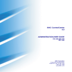
GDS allows users to integrate management of all disk units connected to a Linux server. In a PRIMECLUSTER system, GDS also allows
users to manage all disk units connected to all servers in an integrated manner for shared in a SAN (Storage Area Network) storage
environment as well as for local disk units connected to specific servers.
-1-
Figure 1.2 SAN (Storage Area Network)
In general, multiple servers can be connected to multiple disk units in a SAN environment. Disk-stored data can be accessed from those
servers. This allows simultaneous access to file systems or databases and improves the efficiency of data duplication between the servers
and backup procedures. The problem is that it also carries the risk of data damage, as multiple servers will compete to access the shared
disk. Therefore, volume management functions suitable for the SAN environment are essential.
Since GDS's management function is suitable for a SAN environment, advanced system operation for disk management can be performed
with ease.
The user-friendly functions simplify management, and at the same time, prevent data corruption by operational mistakes.
Figure 1.3 Access Control Mechanism in a SAN Environment
1.2 Functions for High Availability
Failure of hardware related to disk unit interrupts data access, causing applications or systems to stop.
-2-
This section explains functions which protect data from unexpected hardware problems and improve system availability.
1.2.1 Disk Mirroring
Disk mirroring utilizes multiple disks to maintain data synchronization.
GDS provides disk mirroring by creating one logical disk from multiple physical disks.
With GDS disk mirroring, applications can continue disk accesses even if one mirror disk (a disk that is mirrored) fails. Therefore, all the
data in the disk is not damaged and applications can continue normal operations.
Figure 1.4 Disk Mirroring
GDS supports mirroring of single disk units as well as mirroring between disk arrays. It can mirror disk units of various usage and
configuration, including a system disk installed with an operating system, and a disk connected to multiple servers.
Examples of special mirroring implementation are explained below.
1.2.1.1 System Disk Mirroring [PRIMEQUEST]
System disk mirroring can mirror system disks with Linux operating system installed.
If a system disk failure occurs, the entire system probably stops and even booting will become impossible, and operating system
reinstallation will be required. As a result, service stop may remain for a long time.
System disk mirroring ensures continuous system operation even when a failure occurs in part of the disks.
Additionally, it enables system reboot in a situation where disk failure has occurred.
System disk mirroring in the following environments is also supported.
- System disk in the SAN boot environment
- System disk in the KVM host OS
Note
For mirroring the system disk in a SAN boot environment, contact field engineers to check whether the environment is supported.
-3-
Information
In the PRIMEQUEST 1000 series, the system disk can be mirrored only in a UEFI boot environment with RHEL6 (Intel64) or later.
Figure 1.5 System Disk Mirroring
1.2.1.2 Mirroring between Disk Array Unit
GDS can provide mirroring between high-performance and high-reliability disk arrays.
Mirroring two disk arrays connected with Fibre Channel can protect data from unexpected accidents and power shortage.
Moreover, disk units with redundant access paths can also be mirrored with specific software.
-4-
Figure 1.6 Mirroring between Disk Array Unit
1.2.1.3 Shared Disk Mirroring
GDS can mirror shared disk units connected with a cluster system composed of multiple servers (also referred to as nodes).
Such mirroring is called shared disk mirroring in distinction from local disk mirroring that mirrors disks connected to a single node.
The GDS's shared disk mirroring function can be used with applications, such as the GFS Shared File System, that provide simultaneous
access from multiple servers to shared disks, not to mention switch-over or standby type applications.
In the virtual environment (such as Xen, KVM, and VMware), shared disks can be mirrored using GDS which is operated on the guest
OS.
Figure 1.7 Shared Disk Mirroring
-5-
1.2.2 Hot Spare
Overview
"hot spare" can automate mirroring recovery using spare disks in the event of mirrored disk failure.
Figure 1.8 Hot Spare
Spare Disk Automatic Connection
If an I/O error occurs in a disk connected to a mirror group, a spare disk is automatically connected to the mirror group. Subsequently,
synchronization copying for the spare disk takes place to recover normal mirroring.
Spare Disk Automatic Disconnection
After the disk where an I/O error occurred is recovered, the spare disk is automatically disconnected from the mirror group. For example,
if disk failure causes an I/O error and a spare disk is automatically connected, the spare disk will automatically be disconnected after the
failed disk is swapped with another disk and synchronization copying to the new disk is complete.
Hot Spare Mode (Spare Disk Selection Mode)
A spare disk automatically connected in the event of I/O error in a mirrored disk is selected from spare disks that are registered with the
failed disk's class. There are two modes for selecting spare disks: external mode and internal mode.
- External Mode (Default)
If an I/O error occurs in a disk of a disk array unit, this method selects a spare disk that belongs to a different disk case from that of
the failed disk.
If an I/O error occurs in a disk irrelevant to a disk array unit (such as an internal disk), this method selects a spare disk that is connected
to a controller different from that the failed disk is connected to first.
If no applicable spare disk connected to a group, this method selects a spare disk that belongs to the same disk case or is connected
to the same controller as that of the disk with the I/O error is selected.
Features:
If an I/O error occurs in a disk, there are possibilities that the I/O cable of the disk case has an error, the entire disk case is down, or
-6-
the controller has a breakdown. By searching for a spare disk starting from a different disk case or controller from that of a disk with
an I/O error, a normal spare disk can promptly be found and early mirroring recovery becomes possible.
Figure 1.9 Hot Spare in External mode
- Internal Mode
If an I/O error occurs in a disk of a disk array unit, this method selects a spare disk that belongs to the same disk case as that of the
failed disk.
If an I/O error occurs in a disk irrelevant to a disk array unit (such as an internal disk), it selects a spare disk that is connected to the
same controller as that of the failed disk.
When no applicable unconnected spare disk is found there, spare disk automatic connection is not performed.
Features:
A configuration that mirrors disks belonging to different disk unit cases or connected to different controllers is the configuration with
high-availability, which secures continuous operations even if one of the disk cases or controllers fails. By selecting a spare disk that
-7-
belongs to the same disk case or is connected to the same controller as that of the disk with an I/O error, the configuration with highavailability can be maintained.
Figure 1.10 Hot Spare in Internal Mode
Note
The hot spare function cannot be used for system disks.
Note
Points of Concern for Hot Spare
See "A.2.8 Hot Spare."
1.2.3 Hot Swap
Hot swap allows exchange of faulty disk unit parts without stopping the application in the event of a mirror disk failure. With GDS,
administrator does not have to be aware of the system configuration. The system configuration is transparent to the administrator. Therefore,
the administrator can simply select a failed disk displayed in the GUI window to conduct preparation before swapping disks and restoration
through mirroring after the swapping.
If a spare disk has been operating in place of the defective disk unit, the spare disk will disconnect automatically, returning to its original
state.
-8-
Figure 1.11 Hot Swap
Note
Conditions for Hot Swap
The GDS hot swap function is available only for exchanging disks of disk units supporting hot swap.
Do not remove or insert disks of disk units not supporting hot swap. It may cause breakdown or damage data.
1.2.4 Just Resynchronization Mechanism (JRM)
When a system is down due to panic and so on, data must be resynchronized between the disk units after reboot (after cluster application
failover for a cluster system).
Although the user can run an application during this copying process, redundancy will be lost and loads will be imposed during the process.
In order to resolve this problem, GDS offers a mechanism called Just Resynchronization Mechanism (JRM). JRM can complete copying,
which usually takes a few minutes for each 1 GB, by quickly copying only portions where data mirrored by synchronization is not retained.
-9-
Figure 1.12 Just Resynchronization Mechanism (JRM)
Information
What is JRM?
JRM stands for Just Resynchronization Mechanism, a feature that only allows duplication of the damaged part of data.
Information
Three Types of JRM
There are three types of Just Resynchronization Mechanism (JRM): for volumes, for slices and for proxy. For details, see "A.2.13 Just
Resynchronization Mechanism (JRM)."
Note
Root File System Volume Resynchronization [PRIMEQUEST]
Even when the OS is shut down normally, access from the OS to the root file system (/) volume is not canceled. For this reason, at server
startup, resynchronization of the root (/) volume is always performed.
1.3 Functions for High Manageability
GDS supports various tasks related to disk management, such as installation, operation, and maintenance.
Efficient management functions are essential especially in a SAN environment, where one disk is directly shared with multiple servers.
Functions improving disk manageability are explained below.
- 10 -
1.3.1 Operation Management Interface
By registering a disk unit with GDS, system administrators will be able to centrally manage all operation on the disk (configuration setting,
configuration management, operation monitoring, backup, data migration, configuration change, maintenance) via GDS operation
management interface.
Operation management interface provides the GUI (Graphical User Interface), automatic processing, operation log, and CLI (Command
Line Interface) useful for liaising with other applications, allowing easy and intuitive operation even for inexperienced Linux system users.
Since the GUI is Web browser-based, system administrator will be able to centrally monitor and operate from any remote location.
Figure 1.13 Operation Management Interface
See
For the operation methods of the GUI, see "Chapter 3 Starting and Exiting GDS Management View," "Chapter 4 Management View
Screen Elements," and "Chapter 5 Operation."
For the usage methods of CLI, see "Appendix D Command Reference."
For the operations available on GUI and on CLI, see "5.1.9 Operations from GDS Management View."
1.3.2 Centralized Disk Management
By registering all disk units connected to servers with GDS, it becomes possible to perform the centralized management of all operations
on the disks from the GDS operation management interface.
Since disk units managed by GDS are virtualized as logical volumes, there is no need for the application to handle physical disks.
As to disk units, there are no limitations on physical configurations (single disks, disk arrays, multipath), connection configurations (local
connection, shared connection), and intended use (system disks, local disks, cluster switch-over disks, cluster shared disks). Centralized
management can be performed on any disk units.
- 11 -
Whether or not to mirror the managed disk can be determined as necessary. For example, a user may want to manage a disk array with
sufficient availability, without carrying out mirroring.
Figure 1.14 Centralized Disk Management
Note
System Disk Management
The system disk of the following servers can be managed.
- PRIMEQUEST 1000 series (for the UEFI boot environment with RHEL6 (Intel64) or later)
- PRIMEQUEST 500A/500/400 series
1.3.3 Name Management
In Linux System, disks are named in "sdX" format, where "X" is an alphabetical character assigned by the OS, and the administrator
differentiates the disks by the assigned consecutive characters.
This was not a problem if the disk configuration was small, and if the disks were accessed from a certain server. However, when the
environment is such that there are many disks connected, or in a SAN environment where a disk is shared by multiple servers, it is impossible
to manage the disks using consecutive numbers.
With GDS, the administrator can freely name objects such as physical disks and logical volumes. Names that are easy to remember, for
example, those associated with hardware configuration or data contents can be assigned.
Once an object is named, the name remains the same even if the physical configuration is changed. In other words, the user does not have
to make any changes to applications that recognize the name.
- 12 -
Figure 1.15 Free Device Name
1.3.4 Single System Image Environment
In a SAN environment, a disk unit can be accessed from multiple servers.
GDS provides a single system image environment, in which a cluster system with multiple servers (also referred to as nodes) appears as
one system to the users or application.
This single system image environment can be utilized as explained below.
- Application programs sharing the same disk can lookup disks and volumes using the same name from all nodes.
- Application programs can access the disk simultaneously from all nodes. For details, see "Note."
- Application programs can perform operations from all nodes, such as changing the configuration on objects (such as disks and
volumes). Changes are reflected on all nodes.
Figure 1.16 Single System Image Environment
- 13 -
Note
Access Exclusion Control
When the same block is accessed simultaneously, data consistency is maintained by access exclusion control performed by the application
that runs on multiple nodes simultaneously.
1.3.5 Access Control
GDS provides the following access control functions to prevent data damage from events such as an improper operation by the user.
Class Scope
In order to manage a disk unit with GDS, it must be registered with a certain class. A class is like a container that holds multiple disks.
By defining the class attribute called "scope", the user can specify which node set has access, or can perform operation on the disks
registered to that class. Since operation on the disk is restricted to the nodes you specify, there is no risk of changing the configuration by
mistake, or losing data consistency.
Suppose the operation which has a certain disk unit group connected to three nodes; node A, node B, and node C. Some disk units are
accessed only from node A and node B, and other disk units are accessed only from node B and node C.
In this case, two classes should be created to manage the disks shared separately by node A and B. This ensures that access by the node
that is not selected in the class scope is restricted.
Figure 1.17 Class Scope
Starting and Stopping Volume
GDS's logical volume can be started or stopped for each node sharing the volume.
Since a stopped volume cannot be accessed from the node, there is no risk of losing data consistency by mistake.
- 14 -
Figure 1.18 Starting and Stopping Volume
Access Mode
Logical volume has an attribute called "Access mode", which can be defined for each node sharing the volume. There are two access
modes; "Read and write possible" mode, and "Read only possible" mode.
For example, if a certain node will access the logical volume to create data backup, set the mode "Read only possible". That way, you can
prevent writing to the volume by mistake.
Figure 1.19 Access Mode
Lock Volume
When the node or cluster application is activated, logical volume starts automatically and becomes accessible. Likewise, when the cluster
application is terminated, logical volume will also stop. This prevents a node with terminated application from accessing the logical volume.
However, a volume may be started unexpectedly by rebooting a node.
In order to preclude the logical volume from starting in such a situation, the user can define the "Lock volume" attribute. When "Lock
volume" is selected, volume will not be activated even when the node is rebooted, or cluster application activated.
- 15 -
Figure 1.20 Lock Volume
1.3.6 Realizing Large Capacity and I/O Load Balancing
In our current SAN environment, the demand for large capacity disk units and the amount I/O data processing is increasing daily.
This sub-section describes the functions that realize flexible disk configuration and I/O load balancing for efficient management of large
volumetric data.
Note
Logical partitioning, disk concatenation, and disk striping can be applied to local disks and shared disks. They cannot be applied to system
disks.
1.3.6.1 Logical Partitioning
Logical partitioning divides a physical disk into logical devices based on its original method, and not based on the disk slice management
provided by the disk label (partition table).
For physical disks in a Linux system, in general, a maximum of 128 partitions can be used.
GDS allows users to use physical disks and objects equivalent to disks dividing them into a maximum of 1024 (224 for 4.3A00) logical
devices.
For details, see "2.1.4 Logical Volume" and "D.4 sdxvolume - Volume operations."
1.3.6.2 Disk Concatenation
Disk concatenation combines multiple physical disks to form a single, large logical disk.
By using the disk concatenation function, users are able to configure a large-capacity logical disk device without being restricted to the
limitation of one physical disk.
- 16 -
Figure 1.21 Disk Concatenation
1.3.6.3 Disk Striping
Disk striping maps equal-sized data units on multiple disks so that the data is interleaved in sequence among two or more physical disks.
Disk striping function can balance the I/O load by distributing the divided I/O requests to multiple physical disks simultaneously.
You can also stripe concatenated disks.
Figure 1.22 Disk Striping
- 17 -
1.3.6.4 Combining Disk Striping with Mirroring
Concatenation and striping does not provide data redundancy. Since it involves more disks compared to a usual disk configuration, the
risk of data loss caused by a disk failure is actually larger.
GDS delivers data redundancy as well as high-capacity storage and I/O load distribution by mirroring concatenated or striped disks. When
using concatenation or striping, you are recommended to use mirroring as well.
Figure 1.23 Combining Striping and Mirroring
1.3.7 Online Volume Expansion
Overview
Volume expansion is a function that expands the capacity of volumes, retaining volume data. Volume expansion can be conducted without
stopping applications using the volumes. This function is referred to as online volume expansion.
Volumes are expanded by disk area addition to areas after the last blocks of the volumes. Therefore, to expand a volume, there must be
sufficient continuous free space following the last block of the volume.
Figure 1.24 Online Volume Expansion
- 18 -
Concatenation and Online Volume Expansion
Even if there is no sufficient continuous free space after the last block of the volume, online volume expansion will be available by
concatenating unused disk.
Note
Use Conditions on "Concatenation and Online Volume Expansion"
This function can expand only volumes that meet the following conditions.
- Concatenation and mirroring are both applied.
In other words, concatenated disks have been mirrored.
- The number of concatenated disks can be one.
- The multiplicity of mirroring can be one.
For details, see "Concatenation and Online Volume Expansion" in "A.2.14 Online Volume Expansion."
Figure 1.25 Concatenation and Online Volume Expansion
Online Disk Migration and Online Volume Expansion
Even if there is no sufficient continuous free space after the last block of the volume, online volume expansion will be available by migration
of the volume to a disk with sufficient free space. For the volume migration, use the GDS Snapshot online disk migration function.
See
For online disk migration, see "1.5.5 Online Disk Migration."
- 19 -
Figure 1.26 Online Disk Migration and Online Volume Expansion
Online System Volume Expansion [PRIMEQUEST]
By using a combination of this function and the GDS Snapshot's alternative boot environment creation function, online volume expansion
is available for system volumes.
See
For the GDS Snapshot's alternative boot environment creation function, see "1.5.6 Creating an Alternative Boot Environment
[PRIMEQUEST]." For the procedures for expanding system volumes, see "D.21 Volume Expansion Using Commands
[PRIMEQUEST]."
Operating Instructions
Use the sdxvolume -S command. For details, see "D.4 sdxvolume - Volume operations."
Note
Points of Concern for Online Volume Expansion
See "A.2.14 Online Volume Expansion."
1.3.8 Snapshots by Slice Detachment
By temporarily detaching slices from mirror volumes, you can create snapshots (replications) of the volumes. In other words, by use of
detached slices, volume data at the moment can be accessed.
Detached slices are logical devices separated from volumes, and other applications that use the detached slices can run simultaneously
with service applications that use the volumes. For example, backup applications can be executed concurrently with service applications.
- 20 -
For volumes shared on multiple nodes, by separating nodes running service applications that use the volumes from ones running
applications that use detached slices, an operation mode where process loads do not influence on each other can also be established.
After applications that use detached slices end, it is necessary to reattach the detached slices to volumes in order to create snapshots again.
At this point, copying will be performed to synchronize data on the slices and the volumes. For this copying, GDS uses JRM (Just
Resynchronization Mechanism) for slices to realize high-speed resynchronization by copying only the portions that were updated while
slices were detached.
Figure 1.27 Snapshot by Slice detachment
Note
Ensuring Consistency of Snapshot Data
If you create a snapshot while an application is accessing the volume, the data consistency may not be ensured, as the volume data may
be incomplete.
To ensure the consistency of your snapshot data, you must stop the application that is accessing the volume in advance. After creating the
snapshot, start the application again.
For example, when using the volume as a file system such as GFS or ext3, unmount the volume with the umount(8) command before
creating a snapshot, and mount it with the mount(8) command afterwards. Then, you can ensure the consistency of the snapshot data.
- 21 -
To create a snapshot while running the application, the file system or database system you are using to manage the data must be able to
ensure data integrity.
Note
JRM for Slices
JRM for slices speeds up the resynchronization process when attaching a detached slice again to the volume. GDS records the changes
made on the volume and slice in the memory while the slice is being detached. The resynchronization copy performed when the detached
slice is reattached copies the updated portions only to realize high-speed resynchronization.
JRM for slices becomes effective when a slice is detached while the jrm attribute of the slices is on. However, if a system is stopped or if
the slice is taken over by the sdxslice -T command while the slice is detached, just resynchronization is not conducted when the temporarily
detached slice is attached again. Resynchronization is performed by copying the entire data, not only the updated portions.
Therefore, if you plan to shut down the system, or have a slice taken over, attaching the slice to the volume in advance is highly
recommended.
Information
What is JRM?
JRM stands for Just Resynchronization Mechanism, a feature that only allows duplication of the damaged part of data.
Information
Three Types of JRM
There are three types of Just Resynchronization Mechanism (JRM): for volumes, for slices and for proxy. For details, see "A.2.13 Just
Resynchronization Mechanism (JRM)."
1.4 GDS Snapshot Features
GDS Snapshot is an optional product of GDS that provides additional functions to GDS.
GDS secures data from disk failures using the mirroring function and realizes continuous service. However, the mirroring function is not
capable of protecting data against accidental data erasure by the user or data crash due to an application malfunction. Therefore, data back
up is mandatory. In a conventional system, the service must be stopped to back up data. GDS Snapshot provides a function for realizing
the backup operation that does not influence the service and allows for continuous service.
The causes of cessation of services are not only problems such as disk failure and data damage. In a conventional system, the service must
be stopped even for intentional maintenance work such as volume expansion and work applying patches to software. The function provided
by GDS Snapshot also reduces system stop time and service stop time when performing maintenance work.
Once GDS Snapshot is installed, proxy volumes and shadow volumes become available. These volumes are virtual devices that are bound
up with GDS logical volumes. The user can make use of the GDS Snapshot function by operating and accessing those proxy volumes and
shadow volumes.
The following sections discuss the GDS Snapshot functions provided by proxy volumes and shadow volumes.
1.5 Proxy Volume
Snapshots (replications at a certain moment) of volumes for service applications can be created on other volumes. The former volumes
are referred to as the master volumes and the latter as the proxy (or alternate) volumes.
Using this proxy volume will resolve various issues. For example, stopping a system with a large amount of data for backup purposes is
becoming more and more difficult.
- 22 -
Conventionally, data was backed up overnight when no one was on the system. However, as the amount of data grows, backup often
cannot be completed by the following morning. Also, the widespread usage of Internet and service diversification has made it impossible
to stop many systems.
Figure 1.28 Problems Inherent to a 24-hour Operation System
Since the proxy volume can be accessed separately while the service application is accessing the master volume, users can run a backup
application in parallel without worrying about the time.
By using the proxy volume, users can conduct various tasks such as non-disruptive backup, data analysis, verification, and data protection
from disaster, without affecting the main service application.
Figure 1.29 Backup Using the Proxy Volume
The user can utilize given logical volumes managed by GDS as master volumes or proxy volumes, including the root volume (system
volume), local volumes in single server configuration, and shared volumes in cluster configuration. It also provides snapshot operation
that is consistent with GDS's various volume management function, such as access control function.
- 23 -
Figure 1.30 Liaising with Volume Management Function
The snapshot functions using a proxy volume are explained here.
1.5.1 Snapshot by Synchronization
A master volume snapshot can be created by synchronizing data of the master volume and the proxy volume in advance and then separating
the synchronized proxy volume from the master volume at any moment.
Snapshot by synchronization minimizes the influence on the service application and is suitable for routine scheduled backup.
As long as the two volumes are synchronized, snapshot can be created easily by separating the proxy volume from the master volume.
Creation of snapshot will only take a few seconds even if the amount of data is large.
When the proxy volume is rejoined with the master volume for the next snapshot creation, high-speed resynchronization is performed by
copying only updated portions on the master and proxy during the separation using JRM (Just Resynchronization Mechanism) for proxies.
- 24 -
Figure 1.31 Snapshot by Synchronization
Therefore, both the snapshot creation and the resynchronization process before rejoining the proxy with master will have minimal influence
on the service application.
For example, in a situation where loads imposed on disks are higher during the day than at night, if saving data to tape takes no more than
5 hours and resynchronization copying no more than an hour, the routine backup schedule is assumed as follows.
- 25 -
Figure 1.32 Example of a Daily Backup Schedule
Note
JRM for Proxies
JRM for proxies speeds up the just resynchronization process when joining a parted proxy again to the master and when the master data
is restored from the proxy. GDS records the changes made on the master and the proxy on the memory while the proxy is parted. The just
resynchronization conducted when rejoining or restoring copies only updates the updated portions to realize high-speed synchronization.
JRM for proxies is enabled when the pjrm attribute of a proxy volume is set to on and the proxy volume is parted. However, if any node
that is included in the scope of the class is stopped while the proxy is parted, just resynchronization is not put in operation. In other words,
the entire data, not only the updated portions, is copied.
Therefore, if you plan to shut down the system, joining the proxy to the master in advance is highly recommended.
Reference to these matters is not necessary when you are using the copy function of a disk unit.
Information
Three Types of JRM
There are three types of Just Resynchronization Mechanism (JRM): for volumes, for slices and for proxy. For details, see "A.2.13 Just
Resynchronization Mechanism (JRM)."
Note
Ensuring Consistency of snapshot data
If you create a snapshot while an application is accessing the volume, the data consistency may not be ensured, as the volume data will
be incomplete.
To ensure the consistency of your snapshot data, you must stop the application that is accessing the volume in advance. After creating the
snapshot, start the application again.
- 26 -
For example, when using the volume as a file system such as GFS or ext3, unmount the volume with the umount(8) command before
creating a snapshot, and mount it with the mount(8) command afterwards. Then, you can ensure the consistency of the snapshot data.
To create a snapshot while running the application, the file system or database system you are using to manage the data must be able to
ensure data consistency.
For details, see "6.4 Online Backup and Instant Restore through Proxy Volume."
Note
The Difference between a Mirrored Slice and Synchronized Proxy Volume
Although data matches on mirrored slices or synchronized master volumes and proxy volumes, the purposes of use are different.
Mirrored slices are equals, and their purpose is to maintain data redundancy. So even if an abnormality is detected in one of the slices, the
volume can be accessed as long as the other slice is normal.
However, even if the master volume and the proxy volume are synchronized, they are separate volumes and not equals. You may consider
the master the primary volume, and the proxy the secondary volume. This means that even if the proxy volume is normal while all slices
comprising the master volume are abnormal, you cannot continue accessing the master volume. The purpose of proxy volumes is to separate
the master volume in order to perform a different task in parallel, and not to improve the data redundancy used by the service application.
In short, the snapshot by slice detachment is a by-product of mirroring, which is the primary objective, but the primary objective of the
snapshot through use of proxy volumes is creating snapshots.
Therefore, GDS Snapshot provides more flexible disk configuration and supports various tasks.
- 27 -
Figure 1.33 Difference between a Mirrored Slice and Synchronized Proxy Volume
1.5.2 Snapshot Function with No Load to the Server/SAN
Note
The cooperation with the following copy functions are not supported in this version:
- REC of ETERNUS Disk storage system
- EMC TimeFinder
- EMC SRDF
By cooperation with the Advanced Copy function of ETERNUS Disk storage system or TimeFinder and SRDF of EMC'S Symmetrix
storage unit, processes such as copying for resynchronization, copying for maintaining synchronization, and recording the portion upgraded
- 28 -
while proxies are being parted are performed within the disk units. Therefore, snapshots can be created without imposing loads on the
server accessed by the service application, or the SAN (Storage Area Network).
As the operation is identical even when using GDS Snapshot with a disk unit lacking special copy function, there is no need for users to
be aware of the differences between disk units.
Figure 1.34 Snapshot Function with No Load to the Server/SAN
1.5.3 Instant Snapshot by OPC
By cooperation with the OPC (One Point Copy) function provided by ETERNUS Disk storage system, snapshots can be created instantly
at any given moment.
Unlike snapshot by synchronization, instant snapshot by OPC does not require synchronization with volumes in advance, so scheduling
is unnecessary. However, as the copying process will take place within the disk array after the snapshot has been created, I/O performance
of the disk will be reduced until copying is complete.
Note
Instant snapshot by OPC is only available on ETERNUS Disk storage system with the OPC function.
- 29 -
Figure 1.35 Instant Snapshot by OPC
1.5.4 Instant Restore
For example, if a misoperation damages master volume data, you can still restore the master volume data using the proxy volume.
In this case, JRM (Just Resynchronization Mechanism) provides high-speed resynchronization by copying only portions that were updated
while the master and proxy volumes were being separated. You can resume the service application immediately without waiting for the
completion of the copying process. Synchronization copying process will take place in parallel with other tasks.
Users may use this function with any disk unit, as it is not dependent on a specific function of a disk unit.
Note
System Volume Restoration [PRIMEQUEST]
To execute instant restore, the master volume and the proxy volume must be stopped temporarily. An active system volume running as a
file system such as /, /usr, and /var cannot be the restore destination or source of instant restore because it cannot be stopped. For the
method of restoring system volumes back from proxy volumes, see "1.5.6 Creating an Alternative Boot Environment [PRIMEQUEST]."
- 30 -
Figure 1.36 Instant Restore
For example, in a situation where loads imposed on disks are higher during the day than at night, if saving data to tape takes no more than
5 hours and resynchronization copying no more than an hour, the routine backup schedule that enables instant restore always from disks
(proxy volumes) but not from tape is assumed as follows.
- 31 -
Figure 1.37 Example of a Backup Schedule Allowing Instant Restore at All Times
1.5.5 Online Disk Migration
When the master and proxy volumes are synchronized, migration from the physical disk used with the master volume to another is possible
without affecting the service application. This is done by exchanging the slice comprising the master volume with the slice comprising
the proxy volume and is useful in situations such as upgrading your disk units.
- 32 -
Figure 1.38 Online Disk Migration
1.5.6 Creating an Alternative Boot Environment [PRIMEQUEST]
Using the snapshot function by proxy volumes, another boot environment (alternative boot environment) can be created without influencing
the current boot environment during system operation. System stop time at the time of backup and restoration work for system volumes
(/, /usr, /var, /boot, /boot/efi, swap area) can be reduced drastically by using the alternative boot environment. In addition, system and
service stop time when modifying the system such as reconfiguring system volumes and applying patches can also be reduced.
An alternative boot environment can be created with the GDS Snapshot command following the procedure as below.
- Creating snapshots of system volumes
Create snapshots of system volumes in the current boot environment using proxy volumes. Snapshots can be created during system
operation.
- Configuring an alternative boot environment
Enable the system to boot from snapshot volumes (proxy volumes) instead of system volumes in the current boot environment. This
configuration changes system files * copied from the root volume (/) to the proxy volumes when snapshots were created. The current
boot environment is not changed.
*) For RHEL4 or RHEL5: fstab and elilo.conf
For RHEL6
: fstab, grub.conf, and dracut.conf
The environment can be switched to the alternative boot environment by simply specifying the name of a boot device name in the alternative
boot environment and rebooting the system. The original boot environment can be restored by simply specifying the name of a boot device
in the original boot environment and rebooting the system.
Using an alternative boot environment can reduce system and service stop time when performing maintenance work and reconfiguration
work for the system as follows.
- Backing up the system
An alternative boot environment can be assumed as a backup of the system. Since an alternative boot environment can be created
during system operation, stopping the system is no longer necessary at the time of backup work.
- 33 -
- Restoring when the system fails
When booting the system becomes unavailable due to a system disk failure or data crash, the system operation can be resumed by
switching to an alternative boot environment. In addition, data on original system volumes can be restored from data in an alternative
boot environment during system operation in the alternative boot environment, and the original boot environment can be switched
back to by simply rebooting the system.
- Reconfiguring the system
The disk configuration of system volumes can be changed by creating an alternative boot environment and switching to the alternative
boot environment. In addition, expanding the capacity and applying patches for volumes used in the alternative boot environment are
available during system operation. These operations can be performed during system operation, and have no effect on the current boot
environment. If booting an alternative boot environment fails or the performance of an alternative boot environment is improper, the
current boot environment can be switched back to by simply rebooting the system.
Note
SAN Boot Environment
For system disk snapshot in the SAN boot environment using ETERNUS Disk storage system, the Advanced Copy function is not available.
See
For examples of using an alternative boot environment, see "6.2 Backing Up and Restoring a System Disk through an Alternative Boot
Environment [PRIMEQUEST]" and "D.21 Volume Expansion Using Commands [PRIMEQUEST]."
1.6 Shadow Volume
Volumes in other domains (cluster systems or single servers) connected to a SAN can be recognized as volumes in the current node (shadow
volumes) and accessed.
Proxy volumes and replications created with the copy function of a disk unit can also be recognized as shadow volumes and accessed in
exchange for the volumes used in the service. Using shadow volumes on a server that does not belong to the domain running the service
can realize the backup operation that does not impose loads on the domain running the service. Additionally, you can configure a backup
server that consolidates backup of volumes from multiple domains in a SAN environment, and a disaster recovery system that conducts
the service alternatively at a remote place in the unlikely event that disaster occurs.
This section describes the shadow volume feature.
Note
SAN Boot Environment
System volumes in a SAN boot environment are not recognized as shadow volumes.
1.6.1 Accessing Volumes from an External Server
In a SAN environment, disk areas used as volumes in other domains (cluster systems and single servers) can be recognized as volumes
(shadow volumes) and accessed.
This feature allows a server that does not belong to the domain running the service to recognize and access volumes used in the service
via the SAN. Not only the volumes used in the service but also the proxy volumes can also be recognized as shadow volumes by an external
server. This capability enables another service, such as backup, restore, batch processing, and data analyses, to run concurrently with the
service without imposing loads on the CPU, I/O, and the network of the domain running the service.
One server can recognize and access volumes in multiple domains connected to a SAN as shadow volumes. For example, you can configure
a backup server that consolidates the backup and restoration of volumes in multiple domains.
- 34 -
See
For the operation mode and the procedure for backup and restore by shadow volumes through an external server, see "6.6 Backing Up
and Restoring through an External Server."
Figure 1.39 Backup Server
1.6.2 Using the Copy Function of a Disk Unit
Volumes can be copied with the copy function of a disk unit and the copy destination disk areas can be recognized as volumes (shadow
volumes) and accessed.
To run another service concurrently with the service, the application volume must be replicated. The operation mode that uses the copy
destination disk areas created with the copy function of a disk unit is available as well as the operation mode that uses proxy volumes, as
replications of the volumes used in the service.
See
For the operation mode and the procedure for backup and restore using the copy function of a disk unit and using shadow volumes, see
"6.5 Backing Up and Restoring through Disk Unit's Copy Functions."
- 35 -
Figure 1.40 Backing Up a Replication Created with the Disk Unit Copy Function
You can configure a disaster recovery system at a place geographically distant using the copy function between disk bodies. If the domain
running the service is affected by disaster, the disaster recovery system will conduct the service alternatively using the copy destination
disk areas as shadow volumes until the domain recovers from disaster.
Figure 1.41 Disaster Recovery System
- 36 -
Chapter 2 Objects
GDS provides mirroring function and consistent manageability for disk units managed by GDS by virtualizing disk units as logical volumes.
In this chapter, GDS object structure is explained so that you can understand the premise of logical volume management.
As GDS Snapshot, optional software of GDS, is implemented, proxy volumes and shadow volumes become available. By using proxy
volumes and shadow volumes, the backup operation that can be conducted during service without affecting the running service can be
realized.
This chapter systematically describes the virtual object structure that is the underlying basis of GDS and GDS Snapshot functionality to
make it clear.
2.1 SDX Object
Virtual resources managed by GDS are called SDX objects, or objects.
There are five kinds of objects: classes, disks, groups, volumes and slices.
In GDS, these objects are called disk classes, SDX disks, disk groups, logical volumes, and logical slices.
Figure 2.1 Figure: Interrelation of SDX Objects
2.1.1 Disk Class
Disk class is the largest unit managed by GDS. Disk class may be referred to as "class".
In order to manage disk units (physical disks) with GDS, you must first register the physical disk with a certain class. A class is like a
container that holds multiple disks for management.
By using the registered physical disks, GDS creates and manages objects such as disks, groups, volumes, and slices within a class.
Objects including classes can be named as the user wants. Respective names must be unique throughout the entire system.
Note
Same Class Names
- 37 -
When multiple single nodes on which classes with the same name exist are changed over to a cluster system through installation of the
cluster control facility, the duplicate class names come to exist in the cluster system. For details, see "A.2.25 Changing Over from Single
Nodes to a Cluster System."
Attributes
A class has the following attributes.
Name
This attribute identifies the class within a system.
Type
This attribute specifies the type of class. You can set to one of the following.
Root [PRIMEQUEST]
Objects managed in this type of class are available only to the current node.
The following disks can be managed; the system disk, mirror destination disks, spare disks, and disks on which snapshots of the
system disks are created.
In the PRIMEQUEST 1000 series, root classes can be used in a UEFI boot environment with RHEL6 (Intel64) or later.
Local
Objects managed in this type of class are available only to the current node.
Shared
Objects managed in this type of class are sharable with multiple nodes.
Scope
This attribute indicates a group of nodes on which objects in the class are available.
Hot Spare
This attribute indicates the hot spare operation mode. Either of the following values can be set.
on
Hot spare is enabled.
off
Hot spare is disabled. Automatic connections of spare disks are prevented.
Hot Spare Mode
This attribute indicates the spare disk selection mode of automatic connection for hot spare. One of the following values can be set.
External
If an I/O error occurs in a disk of a disk array unit, this method selects a spare disk that belongs to a different disk case from that
of the failed disk.
If an I/O error occurs in a disk irrelevant to a disk array unit (such as an internal disk), it selects a spare disk that is connected to a
different controller from that of the failed disk. When no applicable unconnected spare disk is found there, a spare disk that belongs
to the same disk case or is connected to the same controller as that of the disk with the I/O error, is selected.
Internal
If an I/O error occurs in a disk of a disk array unit, this method selects a spare disk that belongs to the same disk case as that of the
failed disk.
- 38 -
If an I/O error occurs in a disk irrelevant to a disk array unit (such as an internal disk), it selects a spare disk that is connected to
the same controller as that of the failed disk. When no applicable unconnected spare disk is found there, spare disk automatic
connection is not performed.
Operation
The following operations are available for classes.
Create
Registering a disk with the sdxdisk -M command and specifying a new class name will automatically create a new class.
For details on GDS Management View, see "5.2.2.1 Class Configuration."
Delete
Deleting the last registered disk from a class using the sdxdisk -R command will automatically delete the class. You can also delete
the classes with the sdxclass -R command or the sdxconfig Remove command.
For details on GDS Management View, see "5.5.4 Removing a Class."
Status Display
Class status can be displayed with the sdxinfo command.
For details on GDS Management View, see "5.3.1 Viewing Configurations/Statuses and Monitoring Statuses."
Change Attributes
Class attribute values can be changed with the sdxattr -C command.
For details on GDS Management View, see "5.4.1 Class Configuration."
Recover
Closed classes can be recovered with the sdxfix -C command.
The operation from GDS Management View is unsupported.
Backup
The object configuration within a class can be backed up in configuration table format to a configuration file with the sdxconfig Backup
command.
The operation from GDS Management View is unsupported.
Restore
The object configuration of a class can be restored according to the configuration table in the configuration file with the sdxconfig
Restore command.
The operation from GDS Management View is unsupported.
Convert
A configuration table in a configuration file can be converted with the sdxconfig Convert command in order to restore the object
configuration of the class in environment other than the original.
The operation from GDS Management View is unsupported.
Status
A class can have the following status.
Closed
All objects within a class are unavailable for reference.
For details, see "F.1.4 Class Status Abnormality."
Reference
There are the following points of concern for classes.
- 39 -
Rules
A.1.1 Object Name
A.1.2 Number of Classes
Important Points
A.2.1 Managing System Disks
A.2.3 Booting from a CD-ROM Device
A.2.8 Hot Spare
A.2.9 System Disk Mirroring [PRIMEQUEST]
A.2.24 Operation in Cluster System
A.2.25 Changing Over from Single Nodes to a Cluster System
A.2.28 Backing Up and Restoring Object Configuration (sdxconfig)
A.2.35 System Reconfiguration
A.2.36 Operating When There is a Disk in DISABLE Status or There is a Class not Displayed with the sdxinfo Command
Figure 2.2 Disk Class
2.1.2 SDX Disk
Physical disks managed by GDS are registered with a certain class and are called SDX disks, or simply "disks."
Disks that no longer need to be managed with GDS can be deleted from the class and are returned to their original physical disk status.
- 40 -
Attributes
A disk has the following attributes.
Name
This attribute identifies the disk within a class.
Type
This attribute indicates the type of disk. Either of the following values will be set.
Mirror
The disk has been connected to a mirror group.
Stripe
The disk has been connected to a stripe group.
Concatenation
The disk has been connected to a concatenation group.
Switch
The disk is connected to a switch group.
Keep [PRIMEQUEST]
Retains the disk format and data when registered with a class or connected to a group.
Single
A volume can be created without connecting to a group.
Spare
The disk will be used as a spare disk.
Undefined
The disk has been registered with the class without its usage being specified.
Operation
The following operations are available for disks.
Create
A disk can be created by registering a physical disk with a certain class, using the sdxdisk -M command.
For details on GDS Management View, see "5.2.2.1 Class Configuration."
Delete
A disk can be deleted from a class with the sdxdisk -R command.
For details on GDS Management View, see "5.5.4 Removing a Class."
Connect
A disk can be added to a certain group with the sdxdisk -C command.
For details on GDS Management View, see "5.4.2 Group Configuration."
- 41 -
Disconnect
A disk can be disconnected from the group with the sdxdisk -D command.
For details on GDS Management View, see "5.4.2 Group Configuration."
Swap
A disk is made ready for disk swap with the sdxswap -O command.
For details on GDS Management View, see "5.3.4 Disk Swap."
Recover
Swapped disks can be recovered with the sdxswap -I command.
For details on GDS Management View, see "5.3.4 Disk Swap."
Status Display
The disk status can be displayed with the sdxinfo command.
For details on GDS Management View, see "5.3.1 Viewing Configurations/Statuses and Monitoring Statuses."
Change Attributes
Disk attribute values can be changed with the sdxattr -D command.
For details on GDS Management View, see "5.4.1 Class Configuration."
Clear Errors
The I/O error status of SDX disks can be cleared with the sdxfix -D command.
The operation from GDS Management View is unsupported.
Status
A disk can have the following status.
ENABLE
The disk is in the normal status.
Unless you conduct a special operation, or a special event occurs, a disk is usually in the ENABLE status.
DISABLE
Since disk identification information (class and disk names) is not set, data on the disk is inaccessible.
When disk identification information stored in the private slice of a disk is not set at the time of booting the system, the disk will be
in DISABLE status. For example, if a user reboots the system after formatting a disk mistakenly, it will be in this status. If this happens,
all slices related to the disk are made the NOUSE status.
For details when the disk is in DISABLE status, see "F.1.2 Disk Status Abnormality."
SWAP
Data on the disk is inaccessible and the disk is ready for disk swap.
Successful completion of the sdxswap -O command will make the disk the SWAP status. If this happens, all slices related to the disk
are made the NOUSE status.
Reference
There are the following points of concern for disks.
Rules
A.1.3 Number of Disks
A.1.6 Number of Keep Disks [PRIMEQUEST]
Important Points
A.2.2 Restraining Access to Physical Special File
A.2.4 Initializing Disk
- 42 -
A.2.6 Disk Size
A.2.8 Hot Spare
A.2.10 Keep Disk [PRIMEQUEST]
A.2.15 Swapping Physical Disks
A.2.19 To Use EMC Symmetrix
Figure 2.3 SDX Disk
2.1.3 Disk Group
Disk group acts as container for disks that will be mirrored, striped, concatenated or switched. They may be simply referred to as "groups."
Among group attributes is a type attribute. Type attribute values may be "mirror", "stripe", "concat" or "switch". By connecting multiple
disks to a group, the disks within that group can be mirrored, striped, concatenated or switched one another, depending on the group's type
attribute value.
You can also create a hierarchy of groups by connecting a group to another group. A group belonging to another group is called a lower
level group, and a group above that group is called a higher level group.
A group belonging to another group will retain its own function specified by type attribute, while also acting as a disk belonging to that
group. For example, when more than one "stripe" type group is connected to a "mirror" type group, the connected "stripe" type groups
will be mirrored to each other. So the disks belonging to the "stripe" type group will be striped and mirrored.
Attributes
A group has the following attribute.
Name
This attribute identifies the group within a class.
Type
This attribute specifies the type of group. You can set to one of the following.
- 43 -
mirror
Disks and lower level groups belonging to the same group will be mirrored to each other. A maximum of 8 disks and lower level
groups can be connected to a group collectively. In other words, a maximum of eight-way multiplex mirroring is supported.
stripe
Disks and lower level groups connected to the same group will each configure a stripe column, and will be striped. Since a maximum
of 64 columns can be connected, you can stripe across a maximum of 64 columns.
concat
Disks connected to a concatenation group will be concatenated. Since a maximum of 64 disks can be connected, a maximum of
64 disks can be concatenated.
switch
The group consists of one active disk and one or less inactive disk. If an inactive disk is connected, the roles of the active and
inactive disks can be switched.
Stripe Width
This is an attribute of "stripe" type group, which indicates the data unit size when data is striped. The size you can set is (a value of
two raised to the power) x 512 bytes and it conforms the following conditions:
- Minimum value: 512 bytes
- Maximum value: the minimum value among the following
- (A value of two raised to the 30th power) x 512 bytes (= 512 GB)
- Available size of the smallest disk in a group
- Available size of the smallest lower group in a group
Active Disk
This attribute indicates the active disk between disks that are connected to the switch type group.
Operation
The following operations are available for groups.
Create
Indicating a new (higher level) group when connecting a disk with the sdxdisk -C command, or connecting a group with sdxgroup -C
command will automatically create a (higher level) group.
For details on GDS Management View, see "5.2.2.3 Group Configuration."
Delete
Disconnecting the only remaining disk with the sdxdisk -D command, or disconnecting the only remaining lower level group with the
sdxgroup -D command will automatically remove the (higher level) group. You can also delete a group using the sdxgroup -R command.
For details on GDS Management View, see "5.5.3 Removing a Group."
Connect
You can add a group to another group with the sdxgroup -C command. A group that is connected to another group is called a lower
level group, and a group to which the group is added is called a higher level group.
For details on GDS Management View, see "5.4.2 Group Configuration."
Disconnect
The sdxgroup -D command disconnects the lower level group from the higher level group.
For details on GDS Management View, see "5.4.2 Group Configuration."
- 44 -
Status Display
Group status can be displayed with the sdxinfo command.
For details on GDS Management View, see "5.3.1 Viewing Configurations/Statuses and Monitoring Statuses."
Change Attributes
Group attribute values can be changed with the sdxattr -G command.
For details on GDS Management View, see "5.4.2 Group Configuration."
Reference
There are the following points of concern for groups.
Rules
A.1.4 Number of Groups
A.1.7 Creating Group Hierarchy
Important point
A.2.26 Disk Switch
Guide
A.3.1 Guidelines for Mirroring
A.3.2 Guidelines for Striping
A.3.3 Guidelines for Concatenation
A.3.4 Guidelines for Combining Striping with Mirroring
Figure 2.4 Disk Group
2.1.4 Logical Volume
GDS provides mirroring function and unified manageability by virtualizing physical disks as logical volumes.
An application will access the logical volume instead of the physical disk.
Logical volumes are also called "volumes."
There are five kinds of volumes as follows:
- Single Volume Created in a Single Disk
Data will not be redundant. Single volumes are used when it does not necessary to be mirrored, but needs to be managed by GDS. By
connecting the single disk to a mirror group, a single volume can be changed to a mirror volume while retaining its data.
- Mirror Volume Created in a Mirror Group
When multiple disks and lower groups are connected to the mirror group, data will be redundant through the mirroring function.
- 45 -
- Stripe Volume Created in a Stripe Group
The striping function enables I/O load sharing across multiple disks. Data will not be redundant.
- Volume Created in a Concatenation Group
Concatenation group allows users to create a large capacity volume spanning multiple disks. Its data will not be redundant.
- Switch Volume Created in a Switch Group
If an inactive disk is connected to a switch group in addition to the active disk, the active disk can be changed to the inactive disk with
the disk switch function.
A volume created in the highest level group of a hierarchy will feature functions of its lower level groups as well. For example, a mirror
volume created in a mirror group to which more than one stripe group are connected will feature both the I/O load distribution by the
striping function and data redundancy by the mirroring function.
For physical disks in a Linux system, in general, a maximum of 128 partitions can be used. GDS allows users to create both a volume with
a corresponding physical slice and a volume without a corresponding physical slice. So if you total the volumes with and without physical
slices, single disks and groups can be partitioned to a maximum of 1024 (224 for 4.3A00) volumes and be used.
Attributes
A volume has the following attributes.
Name
This attribute identifies the volume within a class.
JRM
This attribute indicates the just resynchronization mechanism mode for volumes.
on
JRM for volumes is enabled.
off
JRM for volumes is disabled.
Lock Volume
This attribute sets the "Lock volume" mode. The value can be set to one of the following.
on
The volume will be locked and prevented from activating.
off
The volume will not be locked.
Access Mode
This attribute sets the default access mode. If a volume is activated without specifying the access mode, the default setting will be
applied. You can set to one of the following.
rw
The default access mode is set to read and write.
ro
The default access mode is set to read only.
- 46 -
Physical Slice
This attribute indicates whether the volume has a physical slice or not. In other words, it indicates if the slice consisting the volume is
registered with the disk label. The value can be set to one of the following. However, note that physical slice attribute for volumes that
are created in stripe group or concatenation group must be set to "off."
on
When the volume is a single volume, a slice in the single disk will be registered with the disk label. When the volume is a mirror
volume, and if there are disks directly connected to the mirror group, the slices on the disks will be registered with the disk label.
When the volume is a switch volume, slices on all of the disks connected to the switch group will be registered with the disk label.
Mirror volumes created in mirror groups to which only lower level groups are connected have no physical slices even if this attribute
is "on".
off
The volume has no physical slice. In other words, no slice in the volume is registered to the disk label.
PJRM
This attribute indicates the just resynchronization mechanism mode for proxies. Either of the following values can be set.
on
JRM for proxies is enabled.
off
JRM for proxies is disabled.
Operation
The following operations are available for volumes.
Create
A volume can be created in a single disk or the highest level group with the sdxvolume -M command.
For details on GDS Management View, see "5.2.2.4 Volume Configuration."
Delete
Volume will be deleted with the sdxvolume -R command.
For details on GDS Management View, see "5.5.2 Removing a Volume."
Start
Volume will be started with the sdxvolume -N command.
For details on GDS Management View, see "4.2.3 Operation."
Stop
Volume will be stopped with the sdxvolume -F command.
For details on GDS Management View, see "4.2.3 Operation."
Expand
The volume size can be expanded with the sdxvolume -S command.
The operation from GDS Management View is unsupported.
Status Display
Volume status can be displayed with the sdxinfo command.
For details on GDS Management View, see "5.3.1 Viewing Configurations/Statuses and Monitoring Statuses."
- 47 -
Change Attributes
Volume attribute values can be changed with the sdxattr -V command.
For details on GDS Management View, see "5.4.3 Volume Configuration."
Copy control
Synchronization copying of volume can be controlled with the sdxcopy command.
For details on GDS Management View, see "5.3.6 Copying Operation."
Recover
Recovery attempt of an abnormal volume can be performed with the sdxfix -V command.
The operation from GDS Management View is unsupported.
Status
A volume can have the following status.
ACTIVE
Valid data is accessible.
After a volume is booted normally, it is given ACTIVE status. Here, there are one or more slices with ACTIVE or COPY (in the
process of background copying) status within the volume.
STOP
Data is inaccessible, but the volume can be booted and made ACTIVE.
However, a proxy volume must first be parted from the master volume before activating. After the volume is stopped normally, it is
given the STOP status. Here, there are one or more slices with STOP or COPY (in process of background copying) status within the
volume.
INVALID
Data is invalid and inaccessible.
Here, the volume cannot be activated since there are no valid slices (ACTIVE or STOP) or slices in the COPY status (in process of
background copying) within the volume.
For details, see "F.1.3 Volume Status Abnormality."
Reference
There are the following points of concern for volumes.
Rules
A.1.5 Number of Volumes
Important Point
A.2.7 Volume Size
A.2.13 Just Resynchronization Mechanism (JRM)
A.2.14 Online Volume Expansion
A.2.22 Data Consistency at the time of Simultaneous Access
A.2.23 Volume Access Mode
- 48 -
Figure 2.5 Logical Volume
- 49 -
Figure 2.6 Logical Partitioning (Physical Slice Attribute)
2.1.5 Logical Slice
Logical slices are the smallest objects managed by GDS. A logical slice is also simply referred to as "slice."
Mirror volume is created by mirroring more than one logical slice. Each mirror volume will have one logical slice for every disk and lower
level group belonging to the mirror group.
A single volume, stripe volume and a volume in concatenation group will each consist of one logical slice.
A switch volume consists of one logical slice, which is on the active disk.
Usually, an application cannot access the slices consisting a volume. But in the case of a mirror volume with its physical slice attribute
set to "on," temporarily detaching the slice will allow the application to directly access the slice. A snapshot (replication) of the volume
can be created with this function.
Attributes
A slice has the following attributes.
Name
This attribute identifies the slice within a class.
JRM
This attribute indicates the just resynchronization mechanism mode for slices.
on
JRM for slices is enabled.
off
JRM for slices is disabled.
Access Mode
This attribute sets the access mode. The value can be set to one of the following.
- 50 -
rw
Sets access mode for read and write.
ro
Sets access mode for read only.
Operation
The following operations are available for slices.
Detach
A snapshot of a mirror volume can be created by detaching one of the slices consisting the mirror volume with the sdxslice -M command.
For details on GDS Management View, see "5.3.2.1 Backup (by Slice Detachment)."
Attach
The temporarily detached slice can be attached to the volume again with the sdxslice -R command.
For details on GDS Management View, see "5.3.2.1 Backup (by Slice Detachment)."
Activate
The detached slice can be activated with the sdxslice -N command.
For details on GDS Management View, see "5.3.2.1 Backup (by Slice Detachment)."
Stop
The detached slice can be stopped with the sdxslice -F command.
For details on GDS Management View, see "5.3.2.1 Backup (by Slice Detachment)."
Take over
Detached slice can be taken over from another node with the sdxslice -T command.
The operation from GDS Management View is unsupported.
Status Display
Slice status can be displayed with the sdxinfo command.
For details on GDS Management View, see "5.3.1 Viewing Configurations/Statuses and Monitoring Statuses."
Change Attributes
Attribute values of the detached slice can be changed with the sdxattr -S command.
The operation from GDS Management View is unsupported.
Status
A slice can have the following status.
ACTIVE
Data is normal, and accessible.
Here, the volume is ACTIVE. The total number of slices that are in the ACTIVE, STOP, or COPY status (in process of background
copying) within the mirror volume indicates the present multiplicity of the mirroring configuration (1 to 8).
STOP
Data is normal, but inaccessible.
Here, the volume is in the STOP status. The total number of slices that are in the STOP, ACTIVE, or COPY (in process of background
copying) status within the mirror volume indicates the present multiplicity of the mirroring configuration (1 to 8).
INVALID
Data is invalid and inaccessible.
When an I/O error is detected in a slice during the mirroring process, the slice becomes INVALID. Promptly identify the problem and
- 51 -
restore the slice based on the disk driver message or the like. After restoring the slice, execute the synchronization copying. When it
ends successfully, the slice will be valid (the slice will be made the ACTIVE or STOP status). If it fails, it will be INVALID again.
COPY
Synchronization copying is in process to ensure the data integrity.
Synchronization copying is executed from a slice in the valid status (ACTIVE or STOP) to a slice in the COPY status. When it ends
successfully, the slice will be made valid (ACTIVE or STOP). If it fails, it will be INVALID.
TEMP
The slice is temporarily detached from the volume and can be accessed independently.
When the sdxslice -M command ends successfully, the slice is made the TEMP status. To restore the status (ACTIVE or STOP),
execute the sdxslice -R command.
TEMP-STOP
The slice is temporarily detached from the mirror volume, but cannot be accessed separately.
To make the slice accessible, activate the slice executing the sdxslice -N command or the sdxslice -T command.
NOUSE
The slice is inaccessible for a special reason.
When the disk is not available for operation (DISABLE or SWAP), all slices related to the disk are made the NOUSE status.
Reference
There are the following points of concern for slices.
Important Points
A.2.11 Creating a Snapshot by Slice Detachment
A.2.13 Just Resynchronization Mechanism (JRM)
- 52 -
Figure 2.7 Logical Slice
- 53 -
2.2 GDS Snapshot Objects
2.2.1 Proxy Object
An SDX object which is related to another SDX object (called master object) and plays the role of substitution of the master object is
called a proxy object.
There are two kinds of proxy objects. The one is a proxy volume and the other is a proxy group.
A proxy volume can be joined and synchronized to a master volume, and they can be temporarily parted to become accessible as separate
volumes. By joining and synchronizing the proxy volume to the master volume and then parting them, snapshot (copy at the moment)
data of the master volume is instantly taken into the proxy volume.
A proxy group which is related to a master group has the same volume configuration as the master group. Each volume in the proxy group
is a proxy volume of the corresponding master volume. By joining and synchronizing the proxy group to the master group and then parting
them, snapshots of all the volumes in the master group are taken into the proxy group at a time.
Operation
The following operations are available for proxy objects.
Join
A pair of specified master and proxy volumes or master and proxy groups will be related and synchronized with the sdxproxy Join
command.
For details on GDS Management View, see "5.2.4.1 Join."
Part
Master-proxy synchronization will be canceled and the proxy will be accessible as another device other than the master using the
sdxproxy Part command. The master-proxy relationship will be maintained. The parted proxy will be a snapshot (a replication) of the
master at that moment.
For details on GDS Management View, see "5.3.2.2 Backup (by Synchronization)."
Rejoin
The parted master and proxy will be resynchronized with the sdxproxy Rejoin command.
For details on GDS Management View, see "5.3.2.2 Backup (by Synchronization)."
Rejoin and Restore
The parted proxy is rejoined with the master, and master volume data will be restored using the proxy with the sdxproxy RejoinRestore
command.
For details on GDS Management View, see "5.3.3 Restore."
Swap
The slices composing the master and those composing the proxy will be exchanged with the sdxproxy Swap command.
For details on GDS Management View, see "5.3.5 Disk Migration."
Relate
A pair of a master volume and a proxy volume or a master group and a proxy group can be related and parted, with the sdxproxy Relate
command.
For details on GDS Management View, see "5.2.4.2 Relate."
Update
Data can be copied (overwritten) from a master to a parted proxy with the sdxproxy Update command. The updated proxy becomes a
snapshot (a replica) of the master at the moment.
For details on GDS Management View, see "5.3.2.3 Backup (by OPC)."
Restore
Data from a parted proxy can be restored back to the master with the sdxproxy Restore command. The proxy data at the moment is
copied (overwritten) to the master.
For details on GDS Management View, see "5.3.3 Restore."
- 54 -
Cancel Copy Session
The session of a copy function of a disk unit residing between the master and the parted proxy can be canceled with the sdxproxy
Cancel command.
The operation from GDS Management View is unsupported.
Configure an Alternative Boot Environment [PRIMEQUEST]
An environment can be set up with the sdxproxy Root command so that the system can be booted with the parted master or proxy.
The operation from GDS Management View is unsupported.
Break
The specified relationship between a pair of volumes or groups as the master and proxy will be cancelled and they will return to
individual objects with the sdxproxy Break command.
For details on GDS Management View, see "5.5.6 Breaking a Proxy."
Status
The relationship between master volumes and proxy volumes will be one of the following statuses. These statuses can be viewed in the
PROXY field for volumes displayed with the sdxinfo command.
Joined
Master and proxy are joined. In this status, the proxy cannot be accessed.
Parted
Proxy is parted from the master and can be accessed independently from the master (unless the volume is stopped explicitly).
Reference
There are the following points of concern for proxy objects.
Rules
A.1.8 Proxy Configuration Preconditions
A.1.9 Number of Proxy Volumes
A.1.10 Proxy Volume Size
A.1.11 Proxy Group Size
Important Points
A.2.12 The Difference between a Mirror Slice and a Proxy Volume
A.2.13 Just Resynchronization Mechanism (JRM)
A.2.16 Object Operation When Using Proxy
A.2.17 Using the Advanced Copy Function in a Proxy Configuration
A.2.18 Instant Snapshot by OPC
A.2.20 Using EMC TimeFinder or EMC SRDF in a Proxy Configuration
A.2.21 Ensuring Consistency of Snapshot Data
- 55 -
Figure 2.8 Operating Proxy Objects
- 56 -
Figure 2.9 Swapping Master Volume and Proxy Volume
- 57 -
Figure 2.10 Swapping Master Group and Proxy Group
2.2.2 Shadow Object
Note
Shadow objects are not supported in this version.
There are five types of shadow object as follows: shadow classes, shadow disks, shadow groups, shadow volumes and shadow slices.
These objects correspond to disk classes, SDX disks, disk groups, logical volumes and logical slices that are SDX objects respectively.
When SDX objects and shadow objects do not have to be classified particularly, they may be called "objects" collectively.
On the server where GDS Snapshot is installed, physical disks that are not registered with disk classes in the same domain and that store
SDX disk management data, can be managed as shadow objects and accessed. Physical disks conforming to one of the following conditions
can be managed as shadow objects.
- Disks registered with a class (local class or shared class) of GDS in another domain and managed as SDX disks
- Disks to which the private slice was copied from an SDX disk registered with a class (local class or shared class) of GDS in another
domain or in the same domain with the disk unit's copy function
Shadow objects have the following characteristics.
- When shadow objects, such as shadow disks and shadow volumes, are configured or broken up, the physical disk format and data
remain unchanged. For this reason, shadow volumes can be created without affecting data stored on the physical disks, and the data
can be read in or write out through the shadow volumes.
- 58 -
- The configuration information of shadow objects is not saved on the private slices but managed on memory. Shadow objects are
cleared by server reboot, but they can be reconfigured. However, if those objects in the same configuration are not created after the
server reboot, restoration is necessary.
For details, see "Rebooting a Node" in "A.2.27 Shadow Volume."
Shadow objects other than shadow disks can be named as desired. The object names must be unique in the entire system. For details on
the shadow disk naming restrictions, see "A.1.1 Object Name."
2.2.2.1 Shadow Class
A shadow class is the shadow object corresponding to a disk class that is an SDX object.
When disk classes and shadow classes do not have to be classified particularly, they may be called "classes" collectively.
Physical disks conforming to one of the following conditions can be registered with shadow classes.
- Disks registered with a class (local class or shared class) of GDS in another domain and managed as SDX disks
If this applies, with one shadow class, a physical disk registered with the class that has the same name in another domain can be
registered. When multiple physical disks are registered with one class in another domain, part or all of those disks can be registered
with a shadow class. It is also possible to register part of those disks to a shadow class and the other to another shadow class.
- Disks to which the private slice was copied from an SDX disk registered with a class (local class or shared class) of GDS in another
domain or the same domain with the disk unit's copy function
If this applies, with one shadow class, a copy destination physical disk of the SDX disk registered with the class that has the same
name can be registered. When multiple physical disks are registered with one class, part or all of such copy destination physical disks
can be registered with a shadow class. It is also possible to register part of such copy destination physical disks to a shadow class and
the other to another shadow class.
In addition, the sizes of the private slices of physical disks to be registered with the same shadow class must be the same.
Attributes
A shadow class has the following attributes.
Name
This attribute identifies the shadow class in a system.
Type
This attribute indicates the type of shadow class. The following value is set.
Local
The object managed in a shadow class is available only on the current node.
Scope
This attribute indicates a group of nodes on which objects in the shadow class are available. The current node name is set.
Operation
The operations other than status display are not available from Management View. Use the command for each operation.
Create
A new shadow class will be automatically created by specifying a new class name when registering a disk with the sdxshadowdisk M command.
Delete
The shadow class will be automatically deleted by deleting the last registered shadow disk from a shadow class with the sdxshadowdisk
-R command.
- 59 -
Status Display
The shadow class status can be displayed with the sdxinfo command. A shadow class is indicated by 1 (one) in the SHADOW field
for class information displayed with the sdxinfo -e long command.
For details on GDS Management View, see "5.3.1 Viewing Configurations/Statuses and Monitoring Statuses."
Status
Unlike a disk class, there is no possibility that a shadow class is closed down.
Reference
There are the following points of concern for shadow classes.
Rules
A.1.1 Object Name
A.1.2 Number of Classes
Important Points
A.2.24 Operation in Cluster System
The disks that are registered with a class in a certain domain (domain alpha in the figure below) and accordingly are managed as SDX
disks can be registered with a shadow class in another domain (domain beta in the figure below) connected to the same SAN.
Figure 2.11 Example of Common Configuration with a Shadow Class
The disk (sdb in the figure below) to which the private slice has been copied from an SDX disk (sda in the figure below) with the disk
unit's copy function can be registered with a shadow class on one of the following nodes.
- Node that is included in the scope of the class to which the SDX disk belongs (node1 or node 2 in the figure below)
- Node that belongs to the domain (domain alpha in the figure below) with which the SDX disk is registered but that is not included in
the scope of its class (node 3 in the figure below)
- 60 -
- Node that does not belong to the domain where the SDX disk is registered (domain alpha in the figure below) but that is connected
to the same SAN (node 4 in the figure above)
Figure 2.12 Example of Configuration Using Disk Unit's Copy Function and a Shadow Class
Note
Physical Device Name
The same physical device name (such as sda) is not necessarily assigned to the identical physical device in domain alpha and domain beta.
2.2.2.2 Shadow Disk
A physical disk registered with a shadow class is called a shadow disk. A shadow disk is the shadow object corresponding to an SDX disk
that is an SDX object.
When SDX disks and shadow disks do not have to be classified particularly, they may be called "disks" collectively.
Attributes
A shadow disk has the following attributes.
Name
This attribute identifies the shadow disk within a shadow class. There are the following restrictions.
- When it is registered with a class in another domain and managed as an SDX disk, the shadow disk must be named as same as the
SDX disk in the said domain.
- When data has been copied on it from an SDX disk with the disk unit's copy function, the shadow disk must be named as same as
the copy source SDX disk.
- 61 -
Type
This attribute indicates the type of shadow disk. Either of the following values will be set.
Mirror
The disk has been connected to a mirror group.
Stripe
The disk has been connected to a stripe group.
Concatenation
The disk has been connected to a concatenation group.
Single
A shadow volume can be created without connecting to a shadow group.
Undefined
The disk has been registered with the shadow class without its usage being specified.
Operation
The operation other than status display is not available from Management View. Use the command for each operation.
Create
A disk will be created by registering a physical disk with a certain shadow class using the sdxshadowdisk -M command.
Delete
The shadow disk can be deleted from a shadow class with the sdxshadowdisk -R command.
Connect
The shadow disk can be added to a certain shadow group with the sdxshadowdisk -C command.
Disconnect
The shadow disk will be disconnected from the shadow group with the sdxshadowdisk -D command.
Status Display
The shadow disk status can be displayed with the sdxinfo command.
For details on GDS Management View, see "5.3.1 Viewing Configurations/Statuses and Monitoring Statuses."
Status
A shadow disk can have the following status.
ENABLE
The shadow disk is in the normal status.
Reference
There are the following points of concern for shadow disks.
Rules
A.1.3 Number of Disks
- 62 -
Important Points
A.2.2 Restraining Access to Physical Special File
A.2.4 Initializing Disk
A.2.6 Disk Size
The physical disk that is registered with a class in a certain domain (domain alpha) with the sdxdisk -M command and accordingly is
managed as an SDX disk can be registered with a shadow class in another domain (domain beta) with the sdxshadowdisk -M command
and accordingly be managed as a shadow disk. The shadow disk must be named as same as the SDX disk.
Figure 2.13 An SDX Disk and a Shadow Disk
The physical disk (sdb in the figure below) to which the private slice has been copied with the disk unit's copy function from the physical
disk that is registered with a class in a certain domain (domain alpha) with the sdxdisk -M command and accordingly is managed as an
SDX disk (sda in the figure below) can be registered with a shadow class in the same domain (domain alpha) or in another domain (domain
beta) with the sdxshadowdisk -M command and accordingly be managed as a shadow disk. The shadow disk must be named as same as
the SDX disk.
Figure 2.14 Disk Unit's Copy Function and a Shadow Disk
Note
Physical Device Name
The same physical device name (such as sda) is not necessarily assigned to the identical physical device in domain alpha and domain beta.
- 63 -
2.2.2.3 Shadow Group
A shadow group is the shadow object corresponding to a disk group that is an SDX object.
When disk groups and shadow groups do not have to be classified particularly, they may be called "groups" collectively.
To access data on a logical volume through a shadow volume, a shadow group must be created in the same configuration as that of the
disk group to which the logical volume belongs. The following configurations must be identical.
- Group type. This can be viewed in the TYPE field displayed with the sdxinfo -G -e long command.
- Disks constituting the group and disks constituting the lower level group. The disk unit's copy function destination disk is also available.
These can be viewed with the sdxinfo -D command and the sdxinfo -G command.
- Order of connecting disks and lower level groups when the group is the stripe type or the concatenation type. This can be viewed in
the DISKS field displayed with the sdxinfo -G command.
- Stripe width when the group is the stripe type. This can be viewed in the WIDTH field displayed with the sdxinfo -G -e long command.
In addition, a shadow volume can be created by connecting only one of the following disks to a shadow group of the mirror type, and thus
data on a single volume or on a slice temporarily detached can be accessed.
- Single disk. The disk unit's copy function destination disk is also available.
- Disk containing a slice temporarily detached (in the TEMP status). The disk unit's copy function destination disk is also available.
Attributes
A shadow group has the following attributes.
Name
This attribute identifies the shadow group within a shadow class.
Type
This attribute indicates the type of shadow group. One of the following values can be set.
mirror
Shadow disks and lower level shadow groups belonging to the shadow group will be mirrored to one another. A maximum of 8
disks and lower level shadow groups may be connected to a shadow group in total. In other words, a maximum of eight-way
multiplex mirroring is supported.
stripe
Shadow disks and lower level shadow groups connected to the shadow group will configure stripe columns respectively and will
be striped. Since a maximum of 64 shadow disks and lower level shadow groups can be connected to a shadow group in total,
striping across a maximum of 64 columns is supported.
concat
Shadow disks connected to the shadow group are concatenated. Since a maximum of 64 shadow disks can be connected to a shadow
group, a maximum of 64 shadow disks can be concatenated.
Stripe Width
This is an attribute of shadow groups of the "stripe" type, which indicates the data unit size when data is striped. The size you can set
is (a value of two raised to the power) x 512 bytes and it conforms the following conditions:
- Minimum value: 512 bytes
- Maximum value: the minimum value among the following
- (A value of two raised to the 30th power) x 512 bytes (= 512 GB)
- Available size of the smallest disk in a group
- 64 -
- Available size of the smallest lower group in a group
Operation
The operation other than status display from Management View is unsupported. Use the command for each operation.
Create
A shadow group (higher level) will automatically be created by specifying a new (higher level) shadow group name when connecting
a shadow disk with the sdxshadowdisk -C command, or connecting a shadow group with the sdxshadowgroup -C command.
Delete
The shadow group (higher level) will be automatically removed by disconnecting the only remaining shadow disk with the
sdxshadowdisk -D command, or by disconnecting the only remaining lower level shadow group with the sdxshadowgroup -D command.
You can also delete a shadow group with the sdxshadowgroup -R command.
Connect
A shadow group will be added to another shadow group with the sdxshadowgroup -C command. A shadow group that is connected to
another shadow group is particularly called a lower level shadow group, and a shadow group to which another shadow group is
connected is particularly called a higher level shadow group.
Disconnect
The lower level shadow group will be disconnected from the higher level shadow group with the sdxshadowgroup -D command.
Status Display
The shadow group status can be displayed with the sdxinfo command.
For details on GDS Management View, see "5.3.1 Viewing Configurations/Statuses and Monitoring Statuses."
Reference
There are the following points of concern for shadow groups.
Rules
A.1.4 Number of Groups
A.1.7 Creating Group Hierarchy
2.2.2.4 Shadow Volume
A volume created in a shadow group or a shadow disk of the single type is called a shadow volume. The users and applications will access
data on the shadow volumes instead of the physical disks. A shadow volume is the shadow object corresponding to a logical volume that
is an SDX object.
When logical volumes and shadow volumes do not have to be classified particularly, they may be called "volumes" collectively.
Create shadow volumes conforming to the following rules in order to use the shadow volumes to access data in the corresponding logical
volumes.
- Equal to the corresponding logical volumes in size. For volume sizes, check the BLOCKS field displayed with the sdxinfo -V
command.
- Having first block numbers consistent with the first block numbers of the corresponding logical volumes. Therefore, create shadow
volumes within the same shadow group or shadow disk in ascending order in conformity to the order of the first block numbers of the
corresponding logical volumes. For the first block numbers of volumes, check the 1STBLK field displayed with the sdxinfo -V
command.
Synchronization copying is not conducted when a shadow volume of the mirror type is created. When a shadow volume corresponding
to a mirror volume is to be created, synchronization of the mirror volume must be ensured in advance with GDS managing that mirror
volume.
- 65 -
Shadow volumes and the corresponding logical volumes are managed independently. For example, the change on the slice status in one
volume is not updated on the slice status in the other volume. For this reason, you must note certain operational particulars when using
shadow volumes. For details, see "A.2.27 Shadow Volume."
Attributes
A shadow volume has the following attributes.
Name
This attribute identifies the shadow volume within a shadow class.
JRM
This attribute identifies the just resynchronization mechanism mode. The following value is set.
off
JRM is inactive.
Lock Volume
This attribute identifies the "Lock volume" mode. The following value is set.
off
The volume will not be locked.
Access Mode
This attribute sets the default access mode. If a volume is activated without specifying the access mode, the default setting will be
applied. The following value is set.
ro
The default is set to read only.
The access mode attribute value cannot be set to rw (read and write). To write data on a shadow volume, the shadow volume must first
be stopped and reactivated in the read and write mode using the sdxshadowvolume -N command with the -e mode=rw option.
Physical Slice
This attribute is always set to off regardless whether the shadow volume has a physical slice, which means the shadow slice is registered
with the disk label.
Operation
The operation other than status display from Management View is unsupported. Use the command for each operation.
Create
A shadow volume can be created in the highest level shadow group or a shadow disk of the single type with the sdxshadowvolume M command.
Delete
The shadow volume can be deleted with the sdxshadowvolume -R command.
Start
The shadow volume can be started with the sdxshadowvolume -N command.
Stop
The shadow volume can be stopped with the sdxshadowvolume -F command.
- 66 -
Status Display
The volume status can be displayed with the sdxinfo command.
For details on GDS Management View, see "5.3.1 Viewing Configurations/Statuses and Monitoring Statuses."
Status
A shadow volume can have the following status.
ACTIVE
Data is accessible.
After a shadow volume is started normally, it is given ACTIVE status. Here, there are one or more shadow slices in the ACTIVE status
in the shadow volume.
STOP
Data is inaccessible, but the shadow volume can be activated and be ACTIVE.
After the shadow volume is stopped normally, it is given STOP status. Here, there are one or more shadow slices in STOP status in
the shadow volume.
Reference
There are the following points of concern for shadow volumes.
Rules
A.1.5 Number of Volumes
Important Point
A.2.7 Volume Size
A.2.23 Volume Access Mode
A.2.27 Shadow Volume
Multiple physical disks virtualized as a logical volume in a certain domain (domain alpha in the figure below) can be virtualized as a
shadow volume in another domain (domain beta in the figure below), and the shadow volume can be used in order to access the data on
the logical volume in domain alpha from domain beta. The primary service (service A in the figure below) can be run with the logical
volume in domain alpha, and another service (service B: for example, backup, restore, and batch processing) can be run with the shadow
volume in domain beta. However, service A and service B cannot be run simultaneously. If they are run simultaneously, data consistency
between disks is not ensured.
- 67 -
Figure 2.15 A Logical Volume and a Shadow Volume
One physical disk temporarily detached from mirroring among multiple physical disks virtualized as a mirror volume in a certain domain
(domain alpha in the figure below) can be virtualized as a shadow volume in another domain (domain beta in the figure below), and the
shadow volume can be used in order to access the data on the temporarily detached slice in domain alpha from domain beta. The primary
service (service A in the figure below) can be run with the mirror volume in domain alpha from which one slice is temporarily detached,
and another service (service C: for example, backup, restore, and batch processing) can be run with the shadow volume in domain beta
simultaneously. However, when a different service (service B in the figure below) is run with the temporarily detached slice in domain
alpha, service B and service C cannot be run simultaneously. If they are run simultaneously, data consistency between disks is not ensured.
- 68 -
Figure 2.16 Mirror Slice Temporary Detachment and a Shadow Volume
Multiple physical disks virtualized as a proxy volume in a certain domain (domain alpha in the figure below) can be virtualized as a shadow
volume in another domain (domain beta in the figure below), and the shadow volume can be used in order to access the data on the proxy
volume in domain alpha from domain beta. The primary service (service A in the figure below) can be run with the master volume in
domain alpha from which the proxy is parted, and another service (service C: for example, backup, restore, and batch processing) can be
run with the shadow volume in domain beta simultaneously. However, when a different service (service B in the figure below) is run with
the proxy volume in domain alpha, service B and service C cannot be run simultaneously. If they are run simultaneously, data consistency
between disks is not ensured.
- 69 -
Figure 2.17 A Proxy Volume and a Shadow Volume
Data on multiple physical disks virtualized as a logical volume in a certain domain (domain alpha in the figure below) can be copied to
other physical disks with the disk unit's copy function, and the copy destination physical disks can be virtualized as a shadow volume in
the same domain (domain alpha) or another domain (domain beta in the figure below). The primary service (service A in the figure below)
can be run with the logical volume in domain alpha, and another service (service B: for example, backup, restore, and batch processing)
can be run in the domain in which the shadow volume was created.
Figure 2.18 Disk Unit's Copy Function and a Shadow Volume
- 70 -
2.2.2.5 Shadow Slice
A shadow slice is a component of a shadow volume. A shadow volume of the mirror type consists of one or more mirrored shadow slices.
A shadow volume of the single type, stripe type, or concatenation type consists of one shadow slice. A shadow slice is the shadow object
corresponding to a logical slice that is an SDX object.
Independent access to a shadow slice detached from a shadow volume of the mirror type is unsupported.
When logical slices and shadow slices do not have to be classified particularly, they may be called "slices" collectively.
Attributes
A shadow slice has the following attributes.
Name
This attribute identifies the shadow slice within a shadow class.
Operation
The following operations are available for shadow slice.
Status Display
The slice status can be displayed with the sdxinfo command.
For details on GDS Management View, see "5.3.1 Viewing Configurations/Statuses and Monitoring Statuses."
Status
A shadow slice can have the following status.
ACTIVE
Data is accessible.
Here, the shadow volume is in the ACTIVE status. The total number of shadow slices in the ACTIVE or STOP status within a shadow
volume of the mirror type indicates the present multiplicity of the mirroring configuration (1 to 8).
STOP
Data is inaccessible.
Here, the shadow volume is in the STOP status. The total number of shadow slices in the ACTIVE or STOP status within a shadow
volume of the mirror type indicates the present multiplicity of the mirroring configuration (1 to 8).
INVALID
Data is inaccessible due to an I/O error.
When an I/O error is detected in a mirrored shadow slice, the shadow slice becomes INVALID.
For details, see "F.1.1 Slice Status Abnormality."
- 71 -
Chapter 3 Starting and Exiting GDS Management View
GDS Management View manages and monitors objects by using the Web browser.
This chapter explains how to start and exit the GDS Management View.
GDS Management View uses Web-Based Admin View / WWW Server for Admin View.
For details on Web-Based Admin View / WWW Server for Admin View, see "Web-Based Admin View Operation Guide."
3.1 Preparation for Starting GDS Management View
In order to start GDS Management View, the following must be completed.
- Decide the user group.
- Set up the client environment.
- Set up the Web environment.
3.1.1 Deciding the User Group
In order to use GDS Management View, you must create user groups that the operating system manages and register the user names on
all nodes where GDS are installed.
3.1.1.1 User Group Types
There are two types of user groups.
wvroot
"wvroot" is a Web-Based Admin View administrator group and is created automatically when Web-Based Admin View is installed.
This permits all kinds of operation management products running on Web-Based Admin View, such as GDS management, environment
setup, logging view, and all.
sdxroot
This is the administrator group for GDS management. This user type can perform GDS Management View operations.
3.1.1.2 Creating User Groups
After installing the software, only user group wvroot will be automatically created.
The other user group sdxroot, explained in "3.1.1.1 User Group Types" must be created as necessary.
User group can be created using the following command.
# groupadd sdxroot
3.1.1.3 Registering to a User Group
You can register a user name to a user group with a command.
Type an appropriate user group such as sdxroot, and execute the following command.
When registering an existing user to a user group
- When registering a group to "Primary Group"
# usermod -g Group_name(you wish to register) User_name
- When registering a group to "Secondary Group"
- 72 -
# usermod -G Group_name(you wish to register) User_name
When registering a new user to a user group
- When registering a group to "Primary Group"
# useradd -g Group_name(you wish to register) User_name
- When registering a group to "Secondary Group"
# useradd -G Group_name(you wish to register) User_name
Note
Registering a User to the wvroot Group
A user registered to the wvroot group will have the equivalent permission as a user assigned to the system administrator group. Only users
responsible for the entire system should be registered to this group.
3.1.2 Setting up the Client Environment
For the operating environments, such as hardware, operating systems, and Web browsers of clients on which GDS Management View is
used, see "Web-Based Admin View Operation Guide."
3.1.3 Setting up the Web Environment
In order to use GDS Management View, you must define the environment for the client and the Web browser.
For details on setting the Web browser, see "Web-Based Admin View Operation Guide."
3.2 Starting the GDS Management View
Start the GDS Management View after all the necessary settings are complete.
3.2.1 Starting Web-Based Admin View Operation Menu
Follow the procedures below to start Web-Based Admin View.
Procedures
1. Start the Web browser on your client.
2. Access the management server by specifying the following URL
When using Java Plug-in.
http://host name:port number/Plugin.cgi
host name
Specify the public LAN IP address for the primary or secondary management server, or host name.
port number
Specify "8081." When the port number has been changed, specify the new port number.
- 73 -
See
For details on changing port numbers, see "Web-Based Admin View Operation Guide."
Note
When the Web-Based Admin View does not start
If you specified the management server's host name for "host name", and the Web-Based Admin View does not start, specify the
public LAN IP address instead.
3. After starting the Web-Based Admin View, the following user input screen appears.
Figure 3.1 User Name Input Screen
Type the user name and password for the management server, and click <OK>.
4. After completing authentication, the top menu of Web-Based Admin View appears.
3.2.2 Web-Based Admin View Operation Menu Functions
The Web-Based Admin View screen supports the following facilities.
Outline
Menu
Global Disk Services
Start the GDS Management View.
See "Web-Based Admin View Operation Guide" about other operation menus.
- 74 -
Figure 3.2 Web-Based Admin View Operation Menu (Top Menu)
Note
The state of Web-Based Admin View Operation Menu
- The Web-Based Admin View menu varies depending on the products installed.
- If a dialog is displayed because of a Web-Based Admin View error, the picture on the right area of the screen turns red. Click the red
picture, and then a hidden dialog is brought to the front. As any errors come into focus, be sure to make the picture viewable.
3.2.3 Starting GDS Management View
Click the GDS management icon on the Web-Based Admin View Operation menu to start the GDS Management screen (hereinafter main
screen).
From the main screen, you can perform GDS object configuration, such as a class or a volume, status confirmation, and disk swap.
For details, see "Chapter 5 Operation"
- 75 -
Figure 3.3 GDS Management Main Screen
3.3 Exiting GDS Management View
How to exit the GDS Management View is described below.
On the [General] menu, click [Exit]. The following message appear
Figure 3.4 Exit Message
Click <Yes>, and Web-Based Admin View (top menu) appears.
Click <No>, and you will return to the main screen.
How to exit Web-Based Admin View is described below.
- Click <Log Out> from one of the following menus; top menu, GDS Management Operation menu, or Common Operation menu.
- Log In screen appears. Exit the browser, or click Back on the browser and exit GUI.
Note
When the login screen remains displayed
- 76 -
After exiting the Web browser, the login screen may remain displayed but will disappear after a while.
3.4 Changing the Web-Based Admin View Settings
When changing one of the following settings after installing Web-Based Admin View, see "Web-Based Admin View Operation Guide"
for details.
- Modifying the IP address of the public LAN
- Modifying the port number of the network service
- Changing the management server
- Modifying the operation of the secondary management server
- Modify the network environment in the management server
- 77 -
Chapter 4 Management View Screen Elements
This chapter explains the screen elements of GDS Management View.
Screen elements refer to the following items:
- screen configuration
- menu configuration and functions
- icon types and object status
- object information
4.1 Screen Configuration
Main Screen
Click <Global Disk Services> from Web-Based Admin View, and the screen below appears.
From the main screen, you can perform GDS object configuration, such as a class and a volume, status confirmation, and disk swap.
You can also configure and view the statuses of GDS Snapshot proxy objects and shadow objects and also operate those proxy objects.
The following operations are unsupported. Use commands for these operations.
- Object operations in classes that include switch groups
(Information of relevant objects is displayed in blue.)
- Operations of GDS Snapshot shadow objects
(Information of relevant objects is displayed in italic format.)
The screen configuration of the main screen is shown below.
- 78 -
Figure 4.1 GDS Management Screen (Main Screen)
Configuration Tree Field
Objects managed with GDS are displayed in a tree-structured directory system.
Each object has an icon depicting the type and the status of the object.
For details on the icon type and status, see "4.3 Icon Types and Object Status."
By selecting the node in the GDS Configuration Tree Field, you can switch between the nodes you want to display or operate.
Object Information Field
Detailed information of objects is displayed in table format.
The displayed contents vary according to the menus selected in [View]:[Details] and the object types selected on the GDS configuration
tree.
For details on displayed contents, see "4.4 Object Information."
Log Information Field
Displays error message output by the GDS daemon program.
Title Bar
Displays screen title (Global Disk Services).
- 79 -
Menu Bar
Displays the menu buttons.
Menu Button
Allows you to control the objects selected on screen.
There are [General], [Settings], [Operation], [View] and [Help].
Drop-Down Menu
When a menu button from the menu bar is selected, a drop-down menu will be displayed.
For details on drop-down menu, see "4.2 Menu Configuration and Functions."
Popup Menu
An on-screen menu that is displayed by a right-click on an object.
[Check Status] in the popup menu displays a description of the state of the object and the help to restore the object if it is faulty.
Pilot Lamp
Shows the status of the monitored objects.
The lamp will indicate the following status.
Pilot Lamp
Status
Meaning
(Gray lit up)
Normal
Normal status.
(Red blinking)
Abnormal
Critical abnormality
(e.g. closed class, invalid volume)
(Red lit up)
Abnormal
When red blinking warning lamp is single-clicked.
(Yellow blinking)
Degradation
- Volume operating at degradation.
(e.g. invalid slice, disabled disk)
- Disk I/O error
(Yellow lit up)
Degradation
When yellow blinking warning lamp is single-clicked.
GDS Configuration Settings screen
Select Configuration from [Settings] menu, and the "GDS Configuration Settings screen" shown below will appear.
Use the <Screen Switching Tab> to switch between "Class Configuration", "Group Configuration", and "Volume Configuration" settings
screens.
- 80 -
Figure 4.2 GDS Configuration Settings Screen
For information on how to set each configuration, see "5.2.2 Operating from the Settings Menu."
4.2 Menu Configuration and Functions
Each menu button has a drop-down menu allowing you to operate the selected object on screen.
This section explains the menu configuration and functions.
The operations for shadow objects available with GDS Snapshot are not supported.
4.2.1 General
- 81 -
Change Monitoring Intervals
Sets the monitoring interval (min) of objects.
Figure 4.3 [General]: [Change Monitoring Intervals] Screen
Note
When Changing Monitoring Intervals
The default value for monitoring intervals is 5 minutes. When GDS Management is restarted, the monitoring interval is initialized to 5
minutes. To change the monitoring interval, modify the monitoring interval value each time GDS Management is restarted.
Exit
Exits GDS Management.
Figure 4.4 [General]: [Exit] Screen
4.2.2 Settings
- 82 -
Class Configuration
Sets the class configuration.
For details, see "5.2.2 Operating from the Settings Menu."
Figure 4.5 [Settings]: [Class Configuration] Screen
Group Configuration
Sets the group configuration.
For details, see "5.2.2 Operating from the Settings Menu."
- 83 -
Figure 4.6 [Settings]: [Group Configuration] Screen
Volume Configuration
Sets the volume configuration.
For details, see "5.2.2 Operating from the Settings Menu."
- 84 -
Figure 4.7 [Settings]: [Volume Configuration] Screen
File System Configuration
Sets the file system configuration.
For details, see "5.2.3 File System Configuration."
- 85 -
Figure 4.8 [Settings]: [File System Configuration] Screen
System Disk Settings [PRIMEQUEST]
Mirrors the system disk.
For details, see "5.2.1 System Disk Settings [PRIMEQUEST]."
- 86 -
Figure 4.9 [Settings]: [System Disk Settings] Screen
Unmirror System Disk [PRIMEQUEST]
Unmirrors the system disk.
For details, see "5.5.5 Unmirroring the System Disk [PRIMEQUEST]."
- 87 -
Figure 4.10 [Settings]: [Unmirror System Disk] Screen
- 88 -
4.2.3 Operation
Swap Physical Disk
Places the physical disk off-line for swapping physical disks.
For details, see "5.3.4 Disk Swap."
Restore Physical Disk
Places the swapped physical disk on-line for restoration after swapping physical disks.
For details, see "5.3.4 Disk Swap."
Detach Slice
Detaches one of the slices from Mirror volume to prepare for backup. The detached slice will become accessible as a separate logical
device.
For details, see "5.3.2.1 Backup (by Slice Detachment)."
Attach Slice
Slice detached by [Detach Slice] is attached to Mirror volume again.
For details, see "5.3.2.1 Backup (by Slice Detachment)."
- 89 -
Stop/Activate Slice
Stop Slice
In order to protect data of the slice which has been detached to prepare for backup, a slice with "temp" status will temporarily become
inaccessible.
Activate Slice
The detached slice which is now inaccessible ("temp-stop" status) as a result of [Stop Slice] operation or switching of nodes will be
reactivated and become accessible.
For details, see "5.3.2.1 Backup (by Slice Detachment)."
Start Copying
A slice with "invalid" or "copy-stop" status as a result of [Cancel Copying] operation will be attached to a mirror volume, and
synchronization copying will be performed.
For details, see "5.3.6 Copying Operation."
Cancel Copying
Execution of copying will be stopped to avoid effects caused by accessing the disk in the process of synchronization copying.
For details, see "5.3.6 Copying Operation."
Start Volume
Starts the stopped volume.
Stop Volume
Stops the volume.
Proxy Operation
Operates proxy objects. This menu is available only if GDS Snapshot is installed.
Join
Relates proxy objects to master objects and synchronizes them as preparation for snapshot creation by synchronization, or online disk
migration.
For details, see "5.2.4.1 Join."
Part
Parts joined proxies from masters temporarily to make them accessible as logical devices that are different from the masters for snapshot
creation by synchronization. The parted proxies can be used as snapshots (replicas) of the masters at the moment.
For details, see "5.3.2.2 Backup (by Synchronization)."
Rejoin
Joins parted proxies to masters again and synchronizes them as preparation for snapshot re-creation by synchronization.
For details, see "5.3.2.2 Backup (by Synchronization)."
Relate
Relates proxy objects to master objects and parts them as preparation for snapshot creation by OPC.
For details, see "5.2.4.2 Relate."
- 90 -
Update
Copies (overwrites) data from masters to parted proxies for snapshot creation by OPC. The updated proxies can be used as snapshots
(replicas) of the masters at the moment.
For details, see "5.3.2.3 Backup (by OPC)."
Restore
Copies (overwrites) data from parted proxies to masters for restoration of damaged master data. The masters are recovered by the
proxy data at the moment.
For details, see "5.3.3 Restore."
Swap
Swaps slices of synchronized masters and proxies for online disk migration.
For details, see "5.3.5 Disk Migration."
Break
Breaks the relationships between masters and proxies and makes them unrelated again.
For details, see "5.5.6 Breaking a Proxy."
Change Attributes
Changes the attributes of the selected object.
For details, see "5.4 Changes."
Update Physical Disk Information
You can update the disk information without rebooting the system.
This feature is useful in the situations given below.
- When physical disk size is not displayed properly.
- When you turn on the disk array or the disk unit after booting the system.
- When the disk has become inaccessible while operating the system.
- When resource registration was performed.
Check Status
Displays a description of the state of an object and the help to restore the object if it is faulty.
4.2.4 View
Abnormal Object
Only displays objects with abnormalities; not all objects.
- 91 -
Details
Changes displayed contents in the Object Information Field.
By default, [SDX Object] is selected.
SDX Object
Displays information of volumes, disks and slices.
Proxy Object
Displays information of proxy volumes, proxy groups and slices.
For details on the Objects Information Field, see "4.4 Object Information."
Update Now
Usually, GDS Management screen updates the information on object status at an interval specified by [Change Monitoring Intervals] in
the [General] menu.
If you select [Update Now], object status will be updated immediately regardless to the interval specified by [Change Monitoring Intervals].
In order to recognize the disk again, select [Update Physical Disk Information] from [Operation] menu.
4.2.5 Help
Help
Displays Help information.
4.3 Icon Types and Object Status
GDS Management uses icons to show the status of the objects.
Information
The SDX objects that belong to GDS classes and the shadow objects that belong to GDS Snapshot shadow classes are distinguished by
fonts. Information related to shadow objects is displayed in italics.
The status and the icons of objects are shown below.
1. Nodes
Icon
Status
Meaning
(Green)
Normal
-
(Yellow)
Abnormal
Abnormality within the node
(Red)
Abnormal
Abnormality of the node
- 92 -
2. Adapter
Icon
(Green)
Status
-
Meaning
-
3. Classes (local)
Icon
Status
Meaning
(Green)
Normal
-
(Yellow)
Abnormal
Abnormality within the (local) class
(Red)
Closed
Closed class within the class
4. Classes (shared)
Icon
Status
Meaning
(Green)
Normal
-
(Yellow)
Abnormal
Abnormality within the (shared) class
(Red)
Closed
Closed class within the class
5. Classes (root) [PRIMEQUEST]
Icon
Status
Meaning
(Green)
Normal
-
(Yellow)
Abnormal
Abnormality within the (root) class
Status
Meaning
6. Groups (mirror)
Icon
(Green)
Normal
-
(Yellow)
Abnormal
Abnormality within the (mirror) group
(Red)
Abnormal
Closure of the class to which the (mirror) group belongs
7. Groups (stripe)
Icon
Status
Meaning
(Green)
Normal
-
(Yellow)
Abnormal
Abnormality within the (stripe) group
(Red)
Abnormal
Closure of the class to which the (stripe) group belongs
8. Groups (concat)
Icon
Status
Meaning
(Green)
Normal
-
(Yellow)
Abnormal
Abnormality within the (concat) group
(Red)
Abnormal
Closure of the class to which the (concat) group belongs
- 93 -
9. Groups (switch)
Icon
Status
Meaning
(Green)
Normal
-
(Yellow)
Abnormal
Abnormality within the (switch) group
(Red)
Abnormal
Closure of the class to which the (switch) group belongs
10. Physical disks
Icon
Status
Meaning
(Green)
Normal
-
(Yellow)
Abnormal
Object status of some volumes or slices not active
(Red)
Abnormal
Abnormality within the physical disk
11. Disks connected to a group
Icon
Status
Meaning
(Green)
enabled
Operation enabled
(Yellow)
enabled
Some volumes or slices with status other than active
(Red)
enabled
I/O error on the disk
(Red)
disabled
Operation disabled
(Red)
close
Closure of the class to which the disk belongs
(Light Brown)
swap
Disk swap possible
12. Single disks
Icon
Status
Meaning
(Green)
enabled
Operation enabled
(Yellow)
enabled
Some volumes or slices with status other than active
(Red)
enabled
I/O error on the disk
(Red)
disabled
Operation disabled
(Red)
close
Closure of the class to which the single disk belongs
13. Spare disks
Icon
Status
Meaning
(Green)
enabled
Operation enabled
(Yellow)
enabled
Some volumes or slices with status other than active
(Red)
enabled
I/O error on the disk
(Red)
disabled
Operation disabled
(Red)
close
Closure of the class to which the spare disk belongs
- 94 -
Icon
(Light Brown)
Status
swap
Meaning
Disk swap possible
14. Unused disks
Icon
Status
Meaning
(Green)
enabled
Operation enabled
(Red)
enabled
I/O error on the disk
(Red)
disabled
Operation disabled
(Red)
close
Closure of the class to which the unused disk belongs
(Light Brown)
swap
Disk swap possible
15. Volumes
Icon
Status
Meaning
(Green)
active
Active volume
(Yellow)
copy
Copying
(Yellow)
warning
Object status of some slices not active (except slices in
copying process)
(Black)
stop
Volume stopped
(Red)
invalid
Abnormality of volume
(Red)
close
Closure of the class to which the volume belongs
16. Slices
Icon
Status
Meaning
(Green)
active
Active slice
(Black)
stop
Slice stopped
(Red)
invalid
Abnormality of slice (Invalid data)
(Red)
close
Closure of the class to which the slice belongs
(Blue)
copy
Copying
(Blue)
copy-stop
Synchronization copying temporarily interrupted
(Light Blue)
temp
Slice temporarily excluded (accessible)
(Light Blue)
temp-stop
Slice temporarily excluded (inaccessible)
(Light Brown)
nouse
Operation disabled
17. Proxy volumes
Icon
Status
Meaning
(Green)
active
Active proxy volume
(Yellow)
copy
Copying
- 95 -
Icon
Status
Meaning
(Yellow)
warning
Object status of some slices not active (except slices in
copying process)
(Black)
stop
Proxy volume stopped
(Red)
invalid
Abnormality of proxy volume
(Red)
close
Closure of the class to which the proxy volume belongs
18. Proxy groups
Icon
Status
Meaning
(Green)
Normal
-
(Yellow)
Abnormal
Abnormality within the group
(Red)
Abnormal
Closure of the class to which the group belongs
Note
Abnormality Detected with GDS Management
What GDS Management displays as abnormal is limited to objects detected by GDS.
Therefore, even if the disk unit may have a hardware abnormality, it will be displayed as normal until it is accessed, and then abnormality
is detected.
Identify the hardware error on a disk unit based on the log messages for the disk driver which is output to the /var/log/messages file. For
details, see "F.1.11 Disk Unit Error."
4.4 Object Information
This section describes information displayed in the Main Screen's Object Information Field.
The displayed contents in the Object Information Field vary according to the menus selected in [View]:[Details] and the object types
selected on the GDS configuration tree.
By default, [View]:[Details]:[SDX Object] is selected.
- [View]:[Details]:[SDX Object] shows:
GDS Configuration Tree
Object
Object Information Field
(Upper)
Object Information Field
(Lower)
Volume
Slice information
Disk information
Non-volume
Volume information
Disk information
- [View]:[Details]:[Proxy Object] shows:
GDS Configuration Tree
Object
Object Information Field
(Upper)
Object Information Field
(Lower)
Volume
Proxy volume information
Slice information
Non-volume
Proxy group information
Proxy volume information
The Object Information Field displays the following information.
- 96 -
Field Name
Displayed Information
Volume Information
Volume name, status, assigned class name, size, JRM mode, physical slice
attribute, type, master volume name
Disk Information
Disk name, status, physical disk name, assigned group name, type
Slice Information
Slice name, status, copy status, master-proxy GDS Snapshot copy type
Proxy Volume Information
Proxy volume name, master volume name, status, snapshot creation time (last
parted or updated time), JRM (for rejoin and restore) mode
Proxy Group Information
Proxy group name, master group name
- 97 -
Chapter 5 Operation
This chapter describes the GDS operations from GDS Management View.
From GDS Management View, you can configure, operate, reconfigure, delete, view the configuration of, and monitor the status of GDS
objects (SDX objects). If GDS Snapshot is installed, you can also operate proxy objects and view their configurations and statuses. For
shadow objects, configuration viewing and status monitoring only are possible.
For details on operations supported in GDS Management View, see "5.1.9 Operations from GDS Management View."
5.1 Operation Outline
This section explains the GDS settings and operation management.
Note
In PRIMECLUSTER systems
Before defining the configuration of GDS objects such as classes and volumes, perform the following procedures.
1. Resource Registration
Register shared disk units with the PRIMECLUSTER resource database. For more information, see "Appendix H Shared Disk Unit
Resource Registration."
2. Physical Disk Information Update
From the [Operation] menu in GDS Management View, select [Update Physical Disk Information].
5.1.1 System Disk Settings [PRIMEQUEST]
The operation outline of the setting of the system disk mirroring is shown below.
Figure 5.1 System Disk Settings Operation
See
For details on the operation methods, see "5.2.1 System Disk Settings [PRIMEQUEST]."
- 98 -
5.1.2 Configuration Settings
For configuring objects other than system disks, use the relevant menus for configuration.
The setting procedures differ depending on the type of volume you are creating.
- Single volume configuration settings
- Other volume (mirror volume, stripe volume, volume in a concatenation group) configuration settings
Switch volume creation from GDS Management View is unsupported. For creating those volumes, use commands.
5.1.2.1 Single Volume Configuration Settings
The operation outline of single volume configuration settings is shown below.
Figure 5.2 Single Volume Configuration Settings Operation
See
For details on the operation methods, see "5.2.2 Operating from the Settings Menu."
5.1.2.2 Other Volume Configuration Settings
The operation outline of the configuration settings for volumes other than single volume (mirror volume, stripe volume, volume in a
concatenation group) is shown below.
Switch volume creation from GDS Management View is unsupported. For creating those volumes, use commands.
- 99 -
Figure 5.3 Volume Configuration Settings Operation
See
For details on the operation methods, see "5.2.2 Operating from the Settings Menu."
5.1.3 Backup
Volumes can be backed up while applications using them are running.
The following three backup methods are available.
- Slice detachment
- Synchronization (GDS Snapshot required)
- OPC (GDS Snapshot required)
5.1.3.1 Backup (by Slice Detachment)
The following figure shows the procedures for backing up mirror volumes through snapshot by slice detachment.
- 100 -
Figure 5.4 Backup Operation (by Slice Detachment)
Note
Use Conditions on Snapshot by Slice Detachment
Slices can be detached only from mirror volumes with physical slices. In other words, if disks are not connected directly to mirror groups,
creation of snapshots by slice detachment is impossible. Additionally, this snapshot is impossible with mirror volumes in the root class.
See
- For details on snapshots by slice detachment, see "1.3.8 Snapshots by Slice Detachment."
- For details on the operation methods, see "5.3.2.1 Backup (by Slice Detachment)."
5.1.3.2 Backup (by Synchronization)
The following figure shows the procedures for backing up volumes through use of snapshots (proxy volumes) of GDS Snapshot created
by synchronization.
- 101 -
Figure 5.5 Backup Operation (by Synchronization)
Note
Snapshot by Synchronization Limitation
Snapshots by synchronization can be created only if the master and proxy type is mirror or single. For details, see "A.1.8 Proxy
Configuration Preconditions."
See
- For details on snapshots by synchronization, see "1.5.1 Snapshot by Synchronization."
- For details on the operation methods, see "5.3.2.2 Backup (by Synchronization)."
- 102 -
5.1.3.3 Backup (by OPC)
The following figure shows the procedures for backing up volumes through use of snapshots (proxy volumes) of GDS Snapshot created
by OPC.
Figure 5.6 Backup Operation (by OPC)
See
- For details on snapshots by OPC, see "1.5.3 Instant Snapshot by OPC."
- For details on the operation methods, see "5.3.2.3 Backup (by OPC)."
5.1.4 Restore
The following figure shows the procedures for restoring volumes through use of GDS Snapshot proxy volumes.
- 103 -
Figure 5.7 Restore Operation
See
- To restore with proxy volumes, see "1.5.4 Instant Restore."
- For details on the operation methods, see "5.3.3 Restore."
5.1.5 Disk Swap
The following operations are required for swapping disks in the event of a disk error or for the purpose of preventive maintenance.
Figure 5.8 Disk Swap and Restoration Operation
See
For details on the operation methods, see "5.3.4 Disk Swap."
- 104 -
5.1.6 Disk Migration
The following figure shows the procedures for migrating disks through use of GDS Snapshot proxy volumes.
Figure 5.9 Disk Migration Operation
Note
Disk Migration Precondition
Disk migration is supported only if the master and proxy type is mirror or single.
See
- For disk migration with proxy volumes, see "1.5.5 Online Disk Migration."
- For details on the operation methods, see "5.3.5 Disk Migration."
5.1.7 Configuration Change
The procedure for changing or removing the configuration settings is shown below.
- 105 -
Figure 5.10 Configuration Changing Operation
See
For details on the operation methods, see "5.4 Changes" or "5.5 Removals."
5.1.8 Unmirroring the System Disk [PRIMEQUEST]
The operation outline of unmirroring the system disk is shown below.
Figure 5.11 Unmirroring System Disk Operation
- 106 -
See
For details on the operation methods, see "5.5.5 Unmirroring the System Disk [PRIMEQUEST]."
5.1.9 Operations from GDS Management View
GDS Management View supports the following operations.
Use commands for operations that are unsupported in GDS Management View.
Class operation
Operation
Command Operation
GDS Management View Operation
Create
# sdxdisk -M
For details, see "5.2.2.1 Class Configuration" in "5.2.2
Operating from the Settings Menu."
Remove
# sdxdisk -R or
# sdxclass -R
For details, see "5.5.4 Removing a Class" in "5.5
Removals"
Change attribute
(Class name)
# sdxattr -C
-a name=classname
For details, see "5.2.2.1 Class Configuration" in "5.4
Changes."
Change attribute
(Type)
# sdxattr -C
-a type={local|shared}
For details, see "5.4.1 Class Configuration" in "5.4
Changes."
Change attribute
(Scope)
# sdxattr -C
-a scope=node: node:...
For details, see "5.4.1 Class Configuration" in "5.4
Changes."
Change attribute
(Hot spare)
# sdxattr -C
-a hs={on|off}
Unsupported
Change attribute
(Hot spare mode)
# sdxattr -C
-a hsmode={exbox|bybox}
Unsupported
Restore
# sdxfix -V
Unsupported
Group operation
Operation
Command Operation
GDS Management View Operation
Connect
# sdxdisk -C or
# sdxgroup -C
For details, see "5.2.2.3 Group Configuration" in "5.2.2
Operating from the Settings Menu."
Remove
# sdxdisk -D or
# sdxgroup -D or
# sdxgroup -R
For details, see "5.5.3 Removing a Group" in "5.5
Removals."
Change attribute
(Group name)
# sdxattr -G
-a name=groupname
For details, see "5.4.2 Group Configuration" in "5.4
Changes."
Change attribute
(Active disk)
# sdxattr -G
-a actdisk=disk
Unsupported
Volume operation
Operation
Create
Command Operation
# sdxvolume -M
GDS Management View Operation
For details, see "5.2.2.4 Volume Configuration" in "5.2.2
Operating from the Settings Menu."
- 107 -
Operation
Command Operation
GDS Management View Operation
Remove
# sdxvolume -R
For details, see "5.5.2 Removing a Volume" in "5.5
Removals."
Start
# sdxvolume -N
For details, see "Start Volume" in "4.2.3 Operation."
Stop
# sdxvolume -F
For details, see "Stop Volume" in "4.2.3 Operation."
Expand
# sdxvolume -S
Unsupported
Change attribute
(Volume name)
# sdxattr -V
-a name=volumename
For details, see "5.4.3 Volume Configuration" in "5.4
Changes."
Change attribute
(JRM)
# sdxattr -V
-a jrm={on|off}
For details, see "5.4.3 Volume Configuration" in "5.4
Changes."
Change attribute
(Physical slice)
# sdxattr -V
-a pslice={on|off}
For details, see "5.4.3 Volume Configuration" in "5.4
Changes."
Change attribute
(Lock volume)
# sdxattr -V
-a lock={on|off}
Unsupported
Change attribute
(Access mode)
# sdxattr -V ...
-a mode={rw|ro}
Unsupported
Change attribute
(JRM for proxy)
# sdxattr -V
-a pjrm= off
Unsupported
Start copying
# sdxcopy -B
For details, see "5.3.6 Copying Operation" in "5.3
Operation in Use."
Cancel copying
# sdxcopy -C
For details, see "5.3.6 Copying Operation" in "5.3
Operation in Use."
Restore
# sdxfix -V
Unsupported
Slice operation
Operation
Command Operation
GDS Management View Operation
Detach
# sdxslice -M
For details, see "5.3.2.1 Backup (by Slice Detachment)"
in "5.3 Operation in Use."
Attach
# sdxslice -R
For details, see "5.3.2.1 Backup (by Slice Detachment)"
in "5.3 Operation in Use."
Activate
# sdxslice -N
For details, see "5.3.2.1 Backup (by Slice Detachment)"
in "5.3 Operation in Use."
Stop
# sdxslice -F
For details, see "5.3.2.1 Backup (by Slice Detachment)"
in "5.3 Operation in Use."
Take over
# sdxslice -T
Unsupported
Change attribute
# sdxattr -S
Unsupported
Disk operation
Operation
Command Operation
GDS Management View Operation
Swap
# sdxswap -O
For details, see "5.3.4 Disk Swap" in "5.3 Operation in
Use."
Restore
# sdxswap -I
For details, see "5.3.4 Disk Swap" in "5.3 Operation in
Use."
- 108 -
Operation
Command Operation
GDS Management View Operation
Change attribute
# sdxattr -D
For details, see "5.4.1 Class Configuration" in "5.4
Changes."
Clear errors
# sdxfix -D
Unsupported
Proxy operation
Operation
Command Operation
GDS Management View Operation
Join
# sdxproxy Join
For details, see "5.2.4.1 Join" in "5.2 Settings."
Part
# sdxproxy Part
For details, see "5.3.2.2 Backup (by Synchronization)"
in "5.3 Operation in Use."
Rejoin
# sdxproxy Rejoin
For details, see "5.3.2.2 Backup (by Synchronization)"
in "5.3 Operation in Use."
Rejoin and restore
# sdxproxy RejoinRestore
For details, see "5.3.3 Restore" in "5.3 Operation in
Use."
Swap
# sdxproxy Swap
For details, see "5.3.5 Disk Migration" in "5.3 Operation
in Use."
Relate
# sdxpsoxy Relate
For details, see "5.2.4.2 Relate" in "5.2 Settings."
Update
# sdxpsoxy Update
For details, see "5.3.2.3 Backup (by OPC)" in "5.3
Operation in Use."
Restore
# sdxpsoxy Restore
For details, see "5.3.3 Restore" in "5.3 Operation in
Use."
Cancel hard copy
session
# sdxpsoxy Cancel
Unsupported
Create alternative
boot environment
[PRIMEQUEST]
# sdxproxy Root
Unsupported
Break
# sdxproxy Break
For details, see "5.5.6 Breaking a Proxy" in "5.5
Removals."
Shadow operation
Operation
Command Operation
GDS Management View Operation
Operate shadow
disk
# sdxshadowdisk
Unsupported
Operate shadow
group
# sdxshadowgroup
Unsupported
Operate shadow
volume
# sdxshadowvolume
Unsupported
Operation to display the configuration information
Operation
View
Command Operation
# sdxinfo
GDS Management View Operation
For details, see "5.3.1 Viewing Configurations/Statuses
and Monitoring Statuses" in "5.3 Operation in Use."
- 109 -
Other operations
Operation
Command Operation
GDS Management View Operation
System disk settings
[PRIMEQUEST]
# sdxdisk -M
# sdxdisk -C
# sdxroot -M
<reboot>
For details, see "5.2.1 System Disk Settings
[PRIMEQUEST]" in "5.2 Settings."
Unmirror system
disk
[PRIMEQUEST]
# sdxdisk -D
# sdxroot -R
<reboot>
# sdxvolume -F
# sdxvolume -R
# sdxdisk -D
# sdxdisk -R
For details, see "5.5.5 Unmirroring the System Disk
[PRIMEQUEST]" in "5.5 Removals."
Configuration
parameter
operations
# sdxparam
Unsupported
Object
configuration
operations
# sdxconfig
Unsupported
5.2 Settings
This section explains the GDS setting procedure.
5.2.1 System Disk Settings [PRIMEQUEST]
System Disk Settings allows you to mirror system disks.
For mirroring the system disk, the following environment is required.
- The disk label of the system disk is the GPT type.
- The number of slices on the system disk is 14 or less.
- The system disk has sufficient free space.
- The device of the system volumes (/, /var, /usr, /boot, /boot/efi, or swap area) is defined in the /etc/fstab file by the following formats:
For RHEL4 or RHEL5: device name or LABEL
For RHEL6
: device name, LABEL, or UUID
After reconfiguring the disk to obtain the environment described above, make the settings for the system disk.
For details on necessary free space, refer to "A.2.6 Disk Size."
Note
Disk that will be mirrored by system disk settings
For system disk settings from the GDS Management View, disks with /, /var, /usr, /boot, /boot/efi, and a swap area are recognized as
system disks.
Disks that are recognized as system disks will automatically be the original disks for mirroring. Among /, /var, /usr, /boot, /boot/efi, and
a swap area, disks with only swap areas can be excluded from mirroring, but disks with /, /var, /usr, /boot, and /boot/efi are always to be
mirrored.
- 110 -
Also, physical disks that are not recognized as system disks cannot be mirrored using the [System Disk Settings].
Note
For Safe System Disk Mirroring
To safely mirror the system disk, exit all active applications before proceeding to system disk settings.
During the mirroring process, there may be a considerable degradation of application response time. After completing the system disk
settings, promptly reboot the system.
Note
Information collection and environment configuration before and after setting the system disk
Information collection and environment configuration are required before and after setting the system disk.
For details, see "A.2.9 System Disk Mirroring [PRIMEQUEST]."
How to mirror a system disk
In the [Settings] menu, select [System Disk Settings].
1. Confirming original disks
Figure 5.12 Mirroring Disk Target List
In the [Physical Disk] field, system disks that will be used as original disks will be displayed with a check mark.
For disks with mount information in /etc/fstab, the [Mount Point] field displays their mount points.
- 111 -
Original disks for mirroring with check marks in the [Physical Disk] field are registered as keep disks with the root class and mirrored.
Uncheck system disks not to be registered with the root class.
- It is possible to uncheck system disks for which only swap among /, /var, /usr, /boot, /boot/efi and swap is displayed in the
[Mount Point] field.
- It is impossible to uncheck system disks for which /, /var, /usr, /boot, and /boot/efi are displayed in the [Mount Point] field.
If not mirroring, click <Cancel>.
If mirroring, click <Next>.
2. Creating root class
Figure 5.13 Class Name Setting
Type the class name of the root class.
If the root class is present, the class name cannot be set.
Information
Inputting the Class Name
The class name will be used for the device path name.
/dev/sfdsk/class_name/dsk/volume_name
You must be careful when inputting the class name, as once the volume is created, it cannot be changed.
Note
When Setting the System Disk in Cluster System
- 112 -
When setting the system disk in cluster systems, the class name of the root class should be different for each node.
See
For information on assigning a class name, see "A.1.1 Object Name."
Click <Next> to continue.
3. Creating group
Create the group by selecting the mirror disks.
When multiple system disks that will be used as original disks exist, perform group creation for every original disk.
Figure 5.14 Group Disk Selection: rootGroup
Group name, size and mount point will be displayed.
In the [Group Name], an automatically created group name appears as a default.
Change the [Group Name] if necessary.
In the [Group Configuration Disk] field, the original disk you selected will be displayed.
You cannot remove the original disk from the [Group Configuration Disk] field.
From the [Physical Disk List] field, select the mirror disk (i.e. the disk you want to mirror to) and click <Add>. The disk will be
added to the [Group Configuration Disk] field.
You can select more than one physical disk at a time.
For mirroring disks, add one or more mirror disks. If no mirror disk is added, the original disk is registered with the root class and
managed with GDS but will not be mirrored.
Double-click the [Disk Name] field in the [Group Configuration Disk] field, and change the name.
After adding all disks, click <Next> and create the next group.
Once you finish creating all groups, proceed to register the spare disks.
- 113 -
Note
Physical disks that can be registered as the Group Configuration Disk
GDS Management's system disk settings do not allow you to add a physical disk capacity that is smaller than the original disk. Users
should always add a physical disk that is larger than the original disk.
4. Registering spare disk
Figure 5.15 Spare Disk Selection
To register a spare disk, select the physical disk you want to set as a spare disk from the [Physical Disk List], and click <Add>.
Existing spare disks in the root class cannot be removed from the [Spare Disk] field.
After finishing the registration, click <Next>.
When you do not need to register a spare disk, no setting is necessary. Just click <Next>.
Point
Spare Disk Size
The hot spare function will not operate when there is not sufficient space on a spare disk to copy the configuration of volume in
mirror group. Define the largest disk within the class as the spare disk.
- 114 -
5. Confirming system disk configuration
Figure 5.16 System Disk Configuration Confirmation
Confirm the system disk configuration.
In the [Physical Disk] field, the original disk will be displayed, and in the [Mirror Disk] field, the mirror disk will be displayed.
When mount information of a slice contained in physical disk is set for /etc/fstab, mount point will be displayed in the [Mount Point]
field.
Click <Create> to continue. It may take a few minutes for processing.
Information
Automatically Generated Volume Names
The following volume names are automatically generated when setting the system disk.
- When mount information is set for /etc/fstab, the name will be mount point + "Volume." (e.g. usrVolume) However, root
partition will be rootVolume.
- When mount information is not set for /etc/fstab, the name will be "Volume" + number. (e.g. Volume0001)
- 115 -
6. Completing system disk configuration
Figure 5.17 Setting System Disk Mirroring Complete (For RHEL4 or RHEL5)
Figure 5.18 Setting System Disk Mirroring Complete (For RHEL6)
Confirm that the system disk configuration is complete, and click <OK>.
Figure 5.19 System Reboot Message
These system disk settings will be in effect after the system is rebooted. Click <OK> and reboot the system immediately.
Note
Rebooting the System after System Disk Settings are Completed
After the system disk settings are completed, if you change the system volume names before rebooting the system, the system may
not be started. After the system disk settings are completed, reboot the system immediately without performing GDS setup, and so
on.
Note
JRM and System Disk Settings
JRM (Just Resynchronization Mechanism) for a volume created by system disk settings will be set as "Yes."
To disable the JRM feature, select the volume in the Main screen and change the attribute by clicking [Change Attributes] in the
[Operation] menu.
- 116 -
See
For checking the system disk settings, see "D.22 Checking System Disk Settings Using Commands [PRIMEQUEST]."
5.2.2 Operating from the Settings Menu
From the Main screen, select [XXXXX Configuration] in the [Settings] menu.
Settings screen for different features appears. Use the screen switch tab to switch between "Class Configuration," "Group Configuration"
and "Volume Configuration."
Note
Configuring a System of High Reliability
In order to ensure a system of high reliability, mirroring disks connected to separate I/O adapter, controller and cable is recommended.
5.2.2.1 Class Configuration
In this section, how to create a new class is explained.
In the [Settings] menu, select [Class Configuration]. Class Configuration screen appears.
Figure 5.20 Class Configuration
- 117 -
1. Selecting class name
In the [Class Name] list, select "New."
2. Selecting physical disk
In the [Physical Disk] field, select the physical disk you want to include in the disk class.
You can select more than one physical disk at a time.
Selecting a physical disk will make the <Add> button available.
Note
If all physical disks registered with the class are not the same size, register the largest size disk first. For details, see "A.2.6 Disk
Size."
Figure 5.21 Selecting Physical Disk to Configure Class
Information
Up to 400 physical disks can be selected at a time by running this command.
- 118 -
3. Creating a class
<Add>, and the message below appears.
Figure 5.22 Warning
Click <Yes> to continue, and <No> to cancel.
Click <Yes>, and Class Attributes Definition screen appears.
Figure 5.23 Class Attributes Definition
In the [Class Name] of Class Attributes Definition screen, an automatically created disk class name appears as default. Change the
[Class Name] if necessary, and click <OK>.
Information
Inputting Class Name
Class name will be used for the device path name.
/dev/sfdsk/class_name/dsk/volume_name
You must be careful when inputting the class name, as once the volume is created, it cannot be changed.
Note
Creating Local Type Class with Cluster System
When creating a local type class in cluster system, class name should be set differently for each node.
- 119 -
See
For information on assigning a class name, see "A.1.1 Object Name."
This operation determines the class name.
When using single node, [Type] is fixed to "local" and you cannot change it.
If you click <Cancel> in the Class Attributes Definition screen, registration of the physical disk itself will be canceled.
4. Setting disk attributes
Selecting the [Disk Name] in the [Class Configuration Disk] field allows you to set the disk attributes. From here, you can change
the [Disk Name] and [Type].
a. Changing disk name
Double-click the [Disk Name] in the [Class Configuration Disk] field, and change the name.
b. Changing disk type
Display the [Disk Type] in the [Class Configuration Disk] field and select the disk type you wish to change from the list.
When specifying as a spare disk select "spare." When specifying as a single disk, select "single." Default is set to "undef."
5. Completing class creation
After creating all classes, click <Exit> and close Class Configuration screen.
Note
Classes in Cluster Systems
- Creating a class adds a class resource, and removing a class removes a resource.
- When removing a class resource, remove the class without using the PRIMECLUSTER cldelrsc(8) command.
- Cluster applications that use resources of a class should be set after the volume configuration is complete.
See
For information on how to create a shared type class in cluster systems, see "5.2.2.2 Cluster System Class Configuration."
5.2.2.2 Cluster System Class Configuration
In cluster systems, specify [Type] and [Scope] in the Class Attributes Definition screen.
1. Setting [Type]
Sets the class type.
When creating a new disk class, selecting a physical disk that is not shared by other nodes from the [Physical Disk] field, sets the
type to "local" by default.
Selecting a shared physical disk, sets the type to "shared."
2. Displaying [Scope]
Displays connecting nodes that can share a class.
To change scope, click <Change Scope>.
- 120 -
3. <Change Scope> Button
Changes nodes connecting to class.
Click <Change Scope>, and Change Scope screen appears.
Figure 5.24 Change Scope Screen
- Changing the checkbox in the [Change Scope] dialog box specifies the connecting node. (Multiple specification possible).
- Clicking < OK > of the [Change Scope] dialog box determines the class connecting node.
- Clicking <Cancel> of the [Change Scope] dialog box cancels the changing of the connecting node.
Note
Node Name
A node identifier of PRIMECLUSTER is displayed in the [Node Name] of the [Change scope] screen.
If the node name displayed in this screen does not match with the one displayed in GDS Configuration Tree Field of the main screen,
execute the cftool -l command on the node which is added to or removed from the scope, and then change the check box corresponding
to the displayed node name.
Note
Class Resource
- In a cluster system, creating a class adds a class resource, and removing a class removes a resource.
- When removing a class resource, remove the class without using the PRIMECLUSTER cldelrsc(8) command.
- Cluster applications that use resources of a class should be set after the volume configuration is complete.
See
For information on installation and initial setting of cluster systems, refer to "PRIMECLUSTER Cluster Foundation (CF) Configuration
and Administration Guide."
- 121 -
5.2.2.3 Group Configuration
In this section, how to create a new group is explained.
In the [Settings] menu, select [Group Configuration]. Group Configuration screen appears.
Figure 5.25 Group Configuration
Follow the procedures below to create a new group.
1. Selecting group name
In the [Group Name] list, select "New."
2. Selecting disk/lower level group
In the [Class Configuration Disk/Group] field, select the disk/lower level group you want to include in the disk group.
You can select more than one disk/group at a time.
- 122 -
Selecting a disk/group will make the <Add> button available.
Figure 5.26 Selecting Disk/Lower level group to Configure Group
3. Creating a group
Click <Add>, and the Group Attributes Definition screen appears. You will be able to specify the group attributes such as group
name, type and stripe width.
Figure 5.27 Group Attributes Definition Screen
- 123 -
a. Setting [Group Name]
Enter the group name.
Change the default group name if necessary.
b. Setting [Type]
Set the group type.
Select "mirror" for mirroring, "stripe" for striping, and "concat" for concatenating. The default setting is "mirror."
c. Setting [Stripe Width]
You will be able to enter this field only when you select "stripe" for the [Type].
For the stripe width, you can specify a value of two raised to the power. The default setting is "32."
After setting the attributes, click <Exit> and a new group will be created.
If you click <Cancel> in the Group Attributes Definition screen, connection of the disk itself will be canceled.
See
For information on assigning a group name, see "A.1.1 Object Name."
4. Completing group creation
After creating all groups, click <Exit> and close Group Configuration screen.
5.2.2.4 Volume Configuration
In this section, how to create a new volume is explained.
In the [Settings] menu, select [Volume Configuration]. The Volume Configuration screen appears.
- 124 -
Figure 5.28 Volume Configuration
Follow the procedures below to create a volume.
1. Selecting group/disk
In the [Group and Disk List], select the group or the disk.
2. Selecting unused volume
Click the <Unused> field with a volume icon, and select an unused volume.
Note
Size displayed in the <Unused> field
The size displayed in the <Unused> field is the maximum size that can be created as a single volume.
If any volume has ever been deleted in the relevant group or on the relevant disk, the sum of the sizes displayed in the <Unused>
fields and that of the sizes of the free spaces may not match.
3. Setting volume attributes
Selecting an unused volume will allow you to type in the volume attributes field (Volume Name, Volume Size, JRM, Physical
Slice).
a. Setting [Volume Name]
Type the volume name.
- 125 -
See
For information on assigning a volume name, see "A.1.1 Object Name."
b. Setting [Volume Size]
Type the volume size in MB units, using numbers only.
Note
If Volume Size Does Not Match Cylinder Boundary
- When the specified volume size does not match the cylinder boundary of the disk, it will be automatically adjusted by
rounding up. For details, see "A.2.7 Volume Size."
- The [Disk Size] displayed below the <Unused> field is the "effective size", that is, the value of the disk size from which
the size of private slices is subtracted is displayed. Since volume sizes are adjusted to fit into the cylinder boundary,
volume sizes that can be created may be smaller than the value displayed in [Disk Size].
c. [Maximum Size] button
Sets the value in the [Volume Size] field to the maximum available size.
d. Setting [JRM]
Default is set to "on." Change the setting when you want to disable the just resynchronization feature.
When you select a stripe group or concatenation group in step 1., the setting will fail.
e. Setting [Physical Slice]
Sets the volume's physical slice attribute value. Default is the "on."
on : a volume which consists of physical slices is created.
off : a volume without physical slices is created.
- 126 -
When you select a stripe group or concatenation group in step 1., the setting will fail.
Figure 5.29 Setting Volume Attributes
4. Determining the new volume
After setting the attributes, click <Add>. A new volume will be created.
If you click <Reset>, creation of the new volume will be canceled.
After creating all volumes, click <Exit> and close Volume Configuration screen.
After creating the volume, the volume will be started. You can access to the volume using the following special files.
/dev/sfdsk/class_name/dsk/volume_name
Note
Shared Class Volume Operation
Volume created in a shared class cannot be used from other nodes immediately. If you wish to access from other nodes, you must activate
the volume from the node you wish to access.
After activating the volume, the node which created the volume, and the node which activated the volume will gain access. However,
since operating from two nodes could affect data consistency, you must be careful when operating the volume.
- 127 -
5.2.3 File System Configuration
In this section, how to create a file system in a volume is explained.
If a volume has not started, start the volume and perform the following procedure.
In the [Settings] menu, select [File System Configuration]. File System Configuration screen appears.
Figure 5.30 File System Configuration
1. Selecting a group/disk
In the [Group and Disk List] field, select a group or disk with which you want to perform an operation.
2. Selecting a volume
Select a volume in which you want to create a file system.
- 128 -
3. Setting file system attributes
Selecting a volume will allow you to type in the file system attributes field (File System Type, Mount Point, Mount).
Figure 5.31 Setting File System Attributes
a. Setting [File System Type]
Select the file system type.
b. Setting [Mount Point]
Type the mount point you want to set for /etc/fstab.
c. Setting [Mount]
Select "No".
Once file systems are created in step 4., mount information is added to the /etc/fstab file and "noauto" is specified in the fourth
(mount option) field. After completing step 4., modify the mount information in the /etc/fstab file as needed.
Note
Setting [Mount]
Do not select "Yes." Additionally, do not remove "noauto" from mount information added to the /etc/fstab file. For details,
see "A.2.30 File System Auto Mount."
4. Creating the file system
After setting the attributes, click <Create>. A new file system will be created.
After creating all file systems, click <Exit>.
- 129 -
Note
In Cluster Systems
For using volumes on shared disks as file systems in a cluster system, certain settings are required after creating the file systems.
For details on how to set file systems created on shared disks, see "PRIMECLUSTER Reliant Monitor Services (RMS) with Wizard Tools
Configuration and Administration Guide."
5.2.4 Proxy Configuration
This section describes the procedures for relating proxy objects (proxy volumes or groups) to master objects (volumes or groups) in a
system on which GDS Snapshot is installed.
The following two methods are available.
- Join
Relate a proxy to a master and join them. Synchronization copying from the master to the proxy is launched, and after the copying is
complete, they are synchronized. When joining groups, proxy volumes are created in the proxy group and they are joined to their
corresponding master volumes.
- Relate
Relate a proxy to a master and leave them parted. The statuses and contents of the master and the proxy remain unchanged.
5.2.4.1 Join
This subsection describes procedures for joining proxy volumes or proxy groups to volumes or groups in GDS Snapshot installed systems.
1. Selecting a master volume or a master group
Click the icon of a mirror volume, a single volume, or a mirror group to which a proxy is joined in the Main Screen.
Information
If the number of volumes in a group is more than 400, you cannot select the group as the target to join the proxy group.
- 130 -
2. Selecting the [Join] menu
Select [Operation]:[Proxy Operation]:[Join] in the Main screen.
Figure 5.32 Join
3. Selecting a proxy to be joined
The Select Proxy dialog box appears.
- 131 -
Information
The following figure shows the window for group connection. On the window for volume connection, the <OK> button appears in
the position of the <Next> button.
Figure 5.33 Select Proxy
Select a volume or a group to be joined to the master volume or the master group from the [Available Groups/Volumes].
Volumes or groups conforming to all of the following conditions are selectable.
Volume
Object
Group
- Belongs to the class of the master
- Belongs to the class of the master
group
volume
- Mirror type
- Equal to the master volume in size
(Hierarchized mirror groups are also
selectable. Any mirroring multiplicity
is supported.)
- Mirror type or single type
Conditions
(Volumes created in hierarchized
mirror groups are also selectable. Any
mirroring multiplicity is supported.)
- Does not belong to the group or single
- Includes no volume
- Is not related to other master objects or
proxy objects
disk of the master volume
- Is not related to other master objects
or proxy objects
Note
Status of Proxy Volumes That Can Be Joined
"active" proxy volumes cannot be joined. To join an "active" proxy volume, stop the proxy volume in advance.
- 132 -
When joining volumes, select a volume to be joined to the master volume and click <OK>.
When joining groups, select a group to be joined to the master group and click <Next>.
Clicking <Cancel> cancels the join process.
4. Defining attributes of proxy volumes created in the proxy group
When joining groups, the Volume Attributes Definition dialog box appears.
Figure 5.34 Proxy Volume Attributes Definition
When a proxy group is joined to a master group, proxy volumes are created within the proxy group and joined to corresponding
master volumes within the master group. In the Volume Attributes Definition dialog box, set attributes of such proxy volumes.
a. Proxy Volume Name
Assign volume names of proxy volumes. [Proxy Volume Name] shows default volume names. To change the default value,
click and edit the volume name.
See
For the volume naming conventions, see "A.1.1 Object Name."
Information
Automatically Generated Proxy Volume Names
Proxy volume names are automatically generated as "master volume name" + "_" (underscore) + "proxy group name" (e.g.
volume0001_group0002).
b. JRM
Set JRM (Just Resynchronization Mechanism) for volumes. The default value is "on." To turn "off", uncheck the [JRM] box.
- 133 -
Information
JRM for Volumes
The JRM setting in the Proxy Volume Attributes Definition dialog box is the "JRM for Volumes" of the proxy volume. Note
that it is not the "JRM for Proxies." For details, see "A.2.13 Just Resynchronization Mechanism (JRM)."
When the settings are complete, click <OK>.
To initialize the proxy volume attribute settings, click <Reset>.
Clicking <Cancel> cancels the join process.
5. Confirming
A confirmation dialog box appears asking you whether to join the proxy.
Figure 5.35 Confirming "Join" (Volumes)
To continue the process, click <Yes>. Clicking <No> displays the Select Proxy dialog box shown in step 3. again.
Figure 5.36 Confirming "Join" (Groups)
To continue the process, click <Yes>. Clicking <No> displays the Volume Attributes Definition dialog box shown in step 4. again.
- 134 -
6. Information message of the completion
A message window appears informing you that the join process is complete.
Figure 5.37 Information Message of "Join" Completion
Click <OK> to close the information message window.
5.2.4.2 Relate
This subsection describes the procedures for relating proxy volumes or proxy groups to volumes or groups in GDS Snapshot installed
systems.
Information
Data of Related Masters and Proxies
Even if masters and proxies are related, data of the master objects and the proxy objects remain unchanged.
1. Selecting a master volume or a master group
Click the icon of a mirror volume, a single volume, or a mirror group to which a proxy is related in the Main Screen.
- 135 -
2. Selecting the [Relate] menu
Select [Operation]:[Proxy Operation]:[Relate] in the Main screen.
Figure 5.38 Relate
- 136 -
3. Selecting a proxy to be related
The Select Proxy dialog box appears.
Figure 5.39 Select Proxy
Select a volume or a group to be related to the master volume or the master group from the [Available Groups/Volumes].
Volumes or groups conforming to all of the following conditions are selectable.
Volume
Object
Group
- Belongs to the class of the master
- Mirror type
- Equal to the master volume in size
- Mirror type or single type
Condition
s
- Belongs to the class of the master
group
volume
(Volumes created in hierarchized mirror
groups are also selectable. Any mirroring
multiplicity is supported.)
- Does not belong to the group or single
(Hierarchized mirror groups are also
selectable. Any mirroring multiplicity
is supported.)
- Volume layout (offset and size) is
same as that of the master group
- Is not related to other master objects
disk of the master volume
- Is not related to other master objects or
or proxy objects
proxy objects
Select a volume or a group to be related to the master volume or the master group and click <OK>. Clicking <Cancel> cancels the
relating process.
- 137 -
4. Confirming
A confirmation dialog box appears asking you whether to relate the proxy.
Figure 5.40 Confirming "Relate"
To continue the process, click <Yes>. Clicking <No> displays the Select Proxy dialog box shown in step 3. again.
5. Information message of the completion
A message window appears informing you that the relating process is complete.
Figure 5.41 Information Message of "Relate" Completion
Click <OK> to close the information message window.
5.3 Operation in Use
GDS operates monitoring and maintenance from the Main screen.
This section explains the following operations:
- Viewing Configurations/Statuses and Monitoring Statuses
- Backup
- Restore
- Disk Swap
- Disk Migration
- Copying Operation
5.3.1 Viewing Configurations/Statuses and Monitoring Statuses
In the Main Screen, object configuration and status viewing and status monitoring can be performed.
5.3.1.1 Confirming SDX Object Configuration
Select [SDX Object] in the [View]:[Details] menu to view object configurations according to the following units.
- Object configuration within a node
- 138 -
- Object configuration within a class
- Object configuration within a group
- Object configuration within a single disk
- Object configuration within a volume
For GDS Snapshot shadow objects, the object names, the status and so on are displayed in italics.
Object configuration within a node
Click the node icon in the Configuration Tree field, and all volumes and disks within the specified node appear.
Figure 5.42 Main Screen (for SDX Objects of a Node)
Object configuration within a class
Click the class icon in the Configuration Tree field, and all volumes and disks within the class appear.
- 139 -
Figure 5.43 Main Screen (for SDX Objects of a Class)
Object configuration within a group
Click a group icon in the GDS configuration tree field, and all volumes and disks at any level within the specified group appear. Additionally,
place a mouse pointer on a group icon, and the disks and lower level groups constituting the group appear.
- 140 -
Figure 5.44 Main Screen (for SDX Objects of a Group)
Groups displayed in the GDS configuration tree field are only the highest level groups. You can view the disks and lower level groups
constituting their lower level groups in the Group Configuration screen.
Perform the following procedure.
1. Display the Group Configuration screen.
Select [Group Configuration] in the [Settings] menu on the Main screen, and the Group Configuration screen will appear.
2. Select the group you want to view the configuration in the [Group Name] list.
3. In the [Group Configuration Group/Disk] field, view the disks and lower level groups constituting the group.
In this example, group group0003 has disk disksd0005, disksd0006 and lower level group group0002. In a similar manner, view the
configuration of lower group group0002.
- 141 -
Figure 5.45 Confirming Group Configuration Group/Disk
Object configuration within a single disk
Click a single disk icon in the GDS Configuration Tree Field to view all the volumes within the single disk as well as the single disk.
- 142 -
Figure 5.46 Main Screen (for SDX Objects of a Single Disk)
Object configuration within a volume
Click the volume icon in the Configuration Tree field, and all slices and disks within the specified volume appear.
- 143 -
Figure 5.47 Main Screen (for SDX Objects of a Volume)
5.3.1.2 Viewing Proxy Object Configurations
Select [Proxy Object] in the [View]:[Details] menu to view object configurations according to the following units.
- Proxy object configuration within a node
- Proxy object configuration within a class
- Proxy object configuration related to a group
- Proxy object configuration within a single disk
- Proxy object configuration related to a volume
Proxy object configuration within a node
Click the node icon in the Configuration Tree field, and all proxy groups and proxy volumes within the specified node appear.
- 144 -
Figure 5.48 Main Screen (for Proxy Objects of a Node)
Proxy object configuration within a class
Click the class icon in the Configuration Tree field, and all proxy groups and proxy volumes within the class appear.
- 145 -
Figure 5.49 Main Screen (for Proxy Objects of a Class)
Proxy object configuration related to a group
Click a group icon in the GDS Configuration Tree Field to view the following configuration information.
- All the master groups or proxy groups related to that group
- All the proxy volumes within that group and within proxy groups related to it
- 146 -
Figure 5.50 Main Screen (for Proxy Objects of a Group)
Proxy object configuration within a single disk
Click a single disk icon in the GDS Configuration Tree Field to view all the proxy volumes within that single disk.
- 147 -
Figure 5.51 Main Screen (for Proxy Objects of a Single Disk)
Proxy object configuration related to a volume
Click a volume icon in the GDS Configuration Tree Field to view the following configuration information.
- All the master volumes or proxy volumes related to that volume
- All the slices within that volume or within volumes related to it
- 148 -
Figure 5.52 Main Screen (for Proxy Objects of a Volume)
5.3.1.3 Monitoring Object Status
You can monitor the object status from the Main screen.
Object status will be updated at intervals specified in [Change Monitoring Intervals] in the [General] menu. You may also use [Update]
in the [View] menu to update the status immediately.
When an abnormality is detected with objects, a warning lamp (yellow/red) will flash.
Clicking the flashing lamp will change the lamp to a lit-up lamp.
See
For details on warning lamps, see "4.1 Screen Configuration."
When the object status changes such as by detection of the failed disk, the icon color and description in the status field will change as well.
See
For details on icons, see "4.3 Icon Types and Object Status."
If a disk unit fails during operation, an icon of the disk in which an error is detected will turn red.
Perform recovery work, following procedures described in "5.3.4 Disk Swap."
- 149 -
Figure 5.53 Object Status Monitoring in Main Screen
Clicking [Abnormal Object] in the [View] menu will only display objects with abnormalities, making it easy to resolve the problem even
when a number of disks are connected.
Figure 5.54 Main Screen when [View]: [Abnormal Object] is selected
- 150 -
Note
Abnormality Detected with GDS Management
What GDS Management displays as abnormal is limited to objects detected by GDS.
Therefore, even if the disk unit may have a hardware abnormality, it will be displayed as normal until it is accessed, and the abnormality
is detected.
5.3.1.4 Viewing Object Statuses
In the Main Screen, the following two methods are provided for displaying a detailed description of the state of an object and the help to
restore the object if it is faulty.
- [Check Status] in the popup menu
- [Check Status] in the drop-down menu
Information
Object Status Update
The state of objects is updated at regular intervals specified with [General]:[Change Monitoring Intervals]. To check the latest state, select
[View]:[Update Now].
See
If the state of an object changes due to a disk failure and so on, the corresponding icon color and status field will change. For status indicator
icons, see "4.3 Icon Types and Object Status."
1. Checking the state of an object
Using one of the following methods, check the state of an object.
a. [Check Status] in the popup menu
In the Main Screen, right click the desired object and select [Check Status] from the popup menu.
b. [Check Status] in the drop-down menu
In the Main Screen, click the desired object and select [Operation]:[Check Status].
2. Object Status Window
View the state of the object in the displayed dialog box.
Figure 5.55 Object Status Window
To close the window, click <OK>.
If you see <Help> in the window, click <Help> for a detailed description and the help to restore the object.
- 151 -
5.3.2 Backup
GDS is software that provides a highly reliable system environment at times of failure, allowing you to continue normal service. However,
using a mirrored system environment does not guarantee absolute safety. Computer problems could occur due to hardware, software,
operation error and poor environment. A reliable method for working around to such problems is creating "backups." To minimize the
damage caused by trouble, periodical backup is strongly recommended.
Information
Backing Up and Restoring a System Disk [PRIMEQUEST]
Among system disk volumes, volumes (such as /opt and /home) other than system volumes (/, /usr, /var and swap area) can be backed up
by following the procedures described in this section. For system volume backup and restore, see "6.1 Backing Up and Restoring a System
Disk [PRIMEQUEST]" and "6.2 Backing Up and Restoring a System Disk through an Alternative Boot Environment [PRIMEQUEST]."
5.3.2.1 Backup (by Slice Detachment)
This section describes the procedure for creating backup of a mirror volume making use of a snapshot by detaching a slice. This method
requires the following "slice operations."
- Detach Slice
- Attach Slice
See
- For details on snapshots by slice detachment, see "1.3.8 Snapshots by Slice Detachment."
- For the operation flow, see "5.1.3.1 Backup (by Slice Detachment)."
Note
Use Conditions on Snapshot by Slice Detachment
Slices can be detached only from mirror volumes with physical slices. In other words, if disks are not connected directly to mirror groups,
creation of snapshots by slice detachment is impossible.
This snapshot is also impossible with mirror volumes in the root class.
Information
Restore
When data is restored back to a volume using data backed up in this procedure, data is restored for the access path to that volume, /dev/
sfdsk/class_name/dsk/volume_name. For details, see "5.1.4 Restore."
Slice Detachment
In order to create a backup, you must temporarily exclude one of the slices from volume, and make it accessible as a separate volume.
The procedures are explained below.
1. Displaying the volume status including the slice
In the Main screen, display the volume containing the slice for which you want to create a backup. Click the icon and [Slice
Information] appears.
- 152 -
2. Selecting the slice to detach
In the Slice List, select the slice you want to detach by clicking its icon.
3. Selecting [Detach Slice] menu
In the Main screen [Operation] menu, select [Detach Slice].
Figure 5.56 Detach Slice
4. Setting the environment of the detaching slice
We will set the environment of the detaching slice.
Figure 5.57 Setting the environment of the detaching slice
a. Access Mode
Set the access mode of the detached slice.
- 153 -
The initial value is "Read and write possible."
When you specify "Read only possible," the detached mirror slice will be available for read only. Opening a read-only slice
in write mode will result in an error.
Click <OK> after setting the environment. If you click <Cancel>, the detaching of the slice will be cancelled.
Note
Slice status available for [Detach Slice]
You can only perform [Detach Slice] operation to slices that are in either "active" or "stop" status.
The confirmation screen shown below appears.
To continue the process, click <Yes>. Clicking <No> cancels the slice detachment process.
Figure 5.58 Confirming Slice Detach
5. Backup Using Access Path
Click <Yes>, and message notifying the completion of detach slice appears.
Use the access path specified in the message to proceed with backup.
Figure 5.59 Notifying Detach Slice Complete
Attach Slice
After the backup is complete, the slice that was temporarily detached will be attached to the volume again.
If the volume is activated, synchronization copying will begin.
The procedures are explained below.
- 154 -
1. Selecting the slice to attach
In the Slice Information field, select the mirror slice you want to attach by clicking its icon.
2. Selecting [Attach Slice] menu
In the Main screen [Operation] menu, select [Attach Slice].
Figure 5.60 Attach Slice
The confirmation screen shown below appears.
To continue the process, click <Yes>. Clicking <No> cancels the slice attachment process.
Figure 5.61 Confirming "Attach Slice"
- 155 -
3. Notifying the completion of Attach Slice
Click <OK>, and a message notifying the completion of Attach Slice appears.
Figure 5.62 Notifying Attach Slice Completion
Reliable Backup Procedures
Although the procedure above allows you to use the volume as it is after preparing backup, reliability is affected since one of the slices is
excluded.
To ensure reliability, temporarily add a backup disk and perform synchronization copying. After its completion, exclude the slice.
For safe and reliable backup, follow the procedures below.
1. Register backup disk with class.
2. Connect backup disk to group.
3. After completing synchronization copying, stop service.
4. Detach slice.
5. Resume service.
6. Perform backup using access path for backup.
7. Attach slice.
8. Disconnect backup disk from group.
9. Remove backup disk from class.
Completing procedures 1. and 2. in advance will save the waiting time for synchronization copying in procedure 3., therefore reducing
the time required for backup.
Note
Perform [Detach Slice] after Stopping Services
To ensure integrity of backup data, always stop service before excluding the slice.
You may resume service once [Detach Slice] is complete. You do not have to suspend service during the actual backup process.
When excluding the slice without stopping service, run host programs such as fsck (in case of file system) as necessary.
Stop/Activate Slice
Stop Slice
In order to protect data of the slice which has been detached to prepare for backup, a slice with "temp" status will temporarily become
inaccessible.
1. Selecting the slice to stop
In the Slice Information Field, select the slice you want to stop by clicking the "temp" status slice icon.
- 156 -
2. Selecting [Stop/Activate Slice] menu
In the Main screen [Operation] menu, select [Stop/Activate Slice].
Figure 5.63 Stop Slice
To continue the process, click <Yes>. Clicking <No> cancels the slice stop process.
Activate Slice
Reactivate the slice that has become inaccessible ("temp-stop" status) as a result of performing [Stop Slice] operation or switching of the
nodes, and make it accessible.
1. Selecting the slice to activate
In the Slice Information Field, select the slice you want to reactivate by clicking the "temp-stop" status slice icon.
2. Selecting [Stop/Activate Slice] menu
In the Main screen [Operation] menu, select [Stop/Activate Slice].
Figure 5.64 Activate Slice
To continue the process, click <Yes>. Clicking <No> cancels the slice activation process.
5.3.2.2 Backup (by Synchronization)
This subsection describes the procedures for backing up volumes through use of snapshots of GDS Snapshot by synchronization. This
method requires the following "Proxy Operations."
- Join
- Part
- Rejoin
- 157 -
- Break
See
- For details on snapshots by synchronization, see "1.5.1 Snapshot by Synchronization."
- For the operation flow, see "5.1.3.2 Backup (by Synchronization)."
Point
Keep Proxies Parted If Possible
If proxies are kept parted, they can be used for master data restoration. Therefore, it is recommended to keep proxies parted if possible.
For the restore procedures see "5.3.3 Restore."
Note
"Part" Proxies after Stopping Services
To ensure integrity of backup data, always stop services before executing "Part." You may resume the services once "Part" is complete.
It is unnecessary to stop services when backing up data to tape and so on.
For details, see "A.2.21 Ensuring Consistency of Snapshot Data."
Note
Snapshot by Synchronization Use Conditions
See the following sections for points of concern.
- "A.1.8 Proxy Configuration Preconditions"
- "A.1.9 Number of Proxy Volumes"
- "A.1.10 Proxy Volume Size"
- "A.1.11 Proxy Group Size"
Information
Use Conditions for Copy Functions of Disk Units
See "A.2.17 Using the Advanced Copy Function in a Proxy Configuration" and "A.2.20 Using EMC TimeFinder or EMC SRDF in a Proxy
Configuration."
Join
Join a volume for backup (a proxy volume) to a volume to be backed up (a master volume).
To back up all the volumes within a group simultaneously, join a group for backup (a proxy group) to a group to be backed up (a master
group).
For the "Join" procedures see "5.2.4.1 Join."
- 158 -
Part
Make sure that synchronization copying from a master to a proxy is complete in the Main screen, and part the proxy from the master.
Follow the procedures below.
1. Selecting a proxy to be parted
Click a master volume icon on the GDS Configuration Tree in the Main screen.
To back up all the master volumes within a master group simultaneously, click the master group icon.
Select [View]:[Details]:[Proxy Object] to view all the proxy objects related to the master object selected on the GDS Configuration
Tree, in the Object Information Field.
In this field, click an icon of a proxy volume or a proxy group used for backup.
Note
Proxy Objects That Can Be Parted
Proxy volumes can be parted if they are joined and if copy is complete.
2. Selecting the [Part] menu
Select [Operation]:[Proxy Operation]:[Part].
Figure 5.65 Part
- 159 -
3. Setting the environment for parting the proxy
The Part Proxy dialog box appears.
Figure 5.66 Setting the Part Environment
Set the environment for parting the proxy.
a. Instant Snapshot
Specify whether to change the synchronization mode to the OPC mode.
The default value is "No." If synchronization copying from the master to the proxy is incomplete, the part process will fail.
If this option is set to "Yes", instant snapshots are created with the OPC function. Even if synchronization copying from the
master to the proxy is in progress, the proxy will be parted and then background copying from the master to the proxy will
be executed with the OPC function. If the OPC function is unavailable, the part process will fail.
Note
Instant Snapshot by OPC Use Conditions
See the following sections.
- "A.2.17 Using the Advanced Copy Function in a Proxy Configuration"
- "A.2.18 Instant Snapshot by OPC"
b. Just Resynchronization Mechanism
Set the mode of Just Resynchronization Mechanism (JRM) for proxies. The default value is "on."
See
For details on JRM for proxies, see "A.2.13 Just Resynchronization Mechanism (JRM)."
c. Access Mode
Set the access mode of the parted proxy volume.
The default value is "Read Only." The parted proxy volume will be read-only and an error occurs if it is opened in write mode.
To permit write access to the parted proxy volume, set this option to "Read/Write."
After the settings are complete, click <OK>. Clicking <Cancel> cancels the part process.
- 160 -
4. Information message of the completion
A message window appears informing you that the part process is complete.
Figure 5.67 Information Message of "Part" Completion
Click <OK> to close the information message window.
Back up data through use of the proxy volume.
Rejoin
To re-execute backup, rejoin a parted proxy to a master.
Follow the procedures below.
1. Selecting a proxy to be rejoined
Click an icon of a master volume to be backed up on the GDS Configuration Tree in the Main screen.
To back up all the master volumes in a master group simultaneously, click the master group icon.
Select [View]:[Details]:[Proxy Object] to view all the proxy objects related to the master object selected on the GDS Configuration
Tree, in the Object Information Field. In this field, click an icon of a proxy volume or proxy group used for backup.
- 161 -
2. Selecting the [Rejoin] menu
Select [Operation]:[Proxy Operation]:[Rejoin] in the Main screen.
Figure 5.68 Rejoin
3. Confirming
A confirmation dialog box appears asking you whether to rejoin the proxy.
Figure 5.69 Confirming "Rejoin"
To continue the process, click <Yes>. Clicking <No> cancels the proxy rejoin process.
- 162 -
4. Information message of the completion
A message window appears informing you that the rejoin process is complete.
Figure 5.70 Information Message of "Rejoin" Completion
Click <OK> to close the information message window.
Break
If no more backup is to be executed, break the relationship between the master and the proxy.
For "Break Proxy" procedures see "5.5.6 Breaking a Proxy."
5.3.2.3 Backup (by OPC)
This subsection describes the procedures for backing up volumes through use of snapshots of GDS Snapshot by OPC. This method requires
the following "Proxy Operations."
- Relate
- Update
- Break
See
- For details on snapshots by OPC, see "1.5.3 Instant Snapshot by OPC."
- For the operation flow, see "5.1.3.3 Backup (by OPC)."
Note
"Update" Proxies after Stopping Services
To ensure integrity of backup data, always stop services before executing "Update." You may resume the services once "Update" is
complete. It is unnecessary to stop services when backing up data to tape and so on.
For details, see "A.2.21 Ensuring Consistency of Snapshot Data."
Note
Instant Snapshot by OPC Use Conditions
See the following sections for points of concern.
- "A.1.8 Proxy Configuration Preconditions"
- "A.1.9 Number of Proxy Volumes"
- "A.1.10 Proxy Volume Size"
- 163 -
- "A.1.11 Proxy Group Size"
- "A.2.17 Using the Advanced Copy Function in a Proxy Configuration"
- "A.2.18 Instant Snapshot by OPC"
Relate
Relate a volume for backup (a proxy volume) to a volume to be backed up (a master volume).
To back up all the volumes within a group simultaneously, relate a group for backup (a proxy group) to a group to be backed up (a master
group).
For the "Relate Proxy" procedures see "5.2.4.2 Relate."
Update
Copy (overwrite) data from a master to a proxy with the OPC function.
Follow the procedures below.
1. Selecting a proxy to be updated
Click an icon of a master volume to be backed up on the GDS Configuration Tree in the Main screen.
To back up all the master volumes in a master group, click the master group icon.
Select [View]:[Details]:[Proxy Object] to view all the proxy objects related to the master object selected on the GDS Configuration
Tree, in the Object Information Field. In this field, click an icon of a proxy volume (or a proxy group) used for backup.
Note
Proxy Objects That Can Be Updated
Proxy volumes can be updated if they are parted and in "stop" status.
- 164 -
2. Selecting the [Update] menu
Select [Operation]:[Proxy Operation]:[Update] in the Main screen.
Figure 5.71 Update
3. Setting the environment for updating the proxy
The Update Proxy screen appears.
Figure 5.72 Setting the Update Environment
Set the environment for updating the proxy.
a. Instant Snapshot
Specify whether to apply instant snapshot.
- 165 -
The default value is "No." Wait until copying from the master volume to the proxy volume is complete and start the proxy
volume.
To start the proxy volume immediately without waiting until copying from the master volume to the proxy volume is complete,
set this option to "Yes."
After the settings are complete, click <OK>. Clicking <Cancel> cancels the update process.
4. Information message of the completion
A message window appears informing you that the update process is complete.
Figure 5.73 Information Message of "Update" Completion (No to Instant Snapshot)
If "No" to [Instant Snapshot] was selected when setting the update environment in step 3., check the copy status in the Main screen,
and after the copy is complete, start the proxy volume and execute backup.
Figure 5.74 Information Message of "Update" Completion (Yes to Instant Snapshot)
If "Yes" to [Instant Snapshot] was selected when setting the update environment in step 3., you may start the proxy volume and
execute backup immediately without waiting until copying is complete.
Break
If no more backup is necessary, break the relationship between the master and the proxy.
For "Break Proxy" procedures see "5.5.6 Breaking a Proxy."
5.3.3 Restore
This subsection describes the procedures for restoring volumes through use of GDS Snapshot proxy volumes. This method requires the
following "Proxy Operations."
- Restore
See
- To restore with proxy volumes, see "1.5.4 Instant Restore."
- For the operation flow, see "5.1.4 Restore."
- 166 -
Note
System Volume Restoration [PRIMEQUEST]
The system volumes currently running as file systems such as /, /usr, and /var cannot be stopped, and such volumes cannot be restored
through this procedure. For the system volume restoration methods, see "6.1 Backing Up and Restoring a System Disk
[PRIMEQUEST]" or "6.2 Backing Up and Restoring a System Disk through an Alternative Boot Environment [PRIMEQUEST]."
Stop services using a volume to be restored (a master volume), stop the master volume, and then perform the following procedures.
Restore
Copy (overwrite) data from a proxy to a master.
Follow the procedures below.
1. Selecting a proxy as a restore copy source
Click an icon of a master volume to be restored on the GDS Configuration Tree in the Main screen.
To restore all the master volumes within a master group simultaneously, click the master group icon.
Select [View]:[Details]:[Proxy Object] to view all the proxy objects related to the master object selected on the GDS Configuration
Tree, in the Object Information Field.
In this field, click an icon of a proxy volume (or a proxy group) as a restore copy source.
Point
Backup Generation
Proxy volume data is a replica of master volume data at the moment of snapshot creation. For snapshot creation time, check [Snapshot
Created] time in the proxy volume information field.
Note
Proxy Volumes That Can Be Restore Copy Sources
Proxy volumes can be restore copy sources if they are parted and in "active" or "stop" status.
However, when selecting "Yes" to "Rejoin" for setting the restore environment in step 3., copy sources must be proxy volumes that
are parted and are in "stop" status.
- 167 -
2. Selecting the [Restore] menu
Select [Operation]:[Proxy Operation]:[Restore] in the Main screen.
Figure 5.75 Restore
3. Setting the environment for restoring the master
The Restore Master screen appears.
Figure 5.76 Setting the Restore Environment
Set the environment for restoring the master.
a. Rejoin
Specify whether to rejoin the master and the proxy.
- 168 -
The default value is "Yes." The master and the proxy will be joined, and after copy is complete they will be synchronized. If
the OPC function is unavailable, select "Yes."
To leave the master and the proxy parted and execute restore with the OPC function, set this option to "No."
See
For the OPC function use conditions, see the following sections.
- "A.2.17 Using the Advanced Copy Function in a Proxy Configuration"
- "A.2.18 Instant Snapshot by OPC"
Note
Master Volumes with Mirroring Multiplicity of Two and Higher
Even if the device supports the OPC function, selecting "Yes" to [Rejoin] disables the OPC function. To use the OPC function
for restoration, select "No" to [Rejoin]. However, slices other than the OPC copy destinations will be excluded from mirroring
and the data statuses will be invalid. To restore the master volume mirroring status, select the master volume and execute
[Operation]:[Start Copying] in the Main screen. If not executing [Start Copying], resynchronization copying automatically
starts when the master volume starts.
b. Instant Restore
Specify whether to apply instant restore
The default value is "No." Wait until copying from the proxy volume to the master volume is complete and start the master
volume.
To start the master volume immediately without waiting until copying from the proxy volume to the master volume is
complete, set this option to "Yes."
Note
If "Yes" to [Rejoin] and "Yes" to [Instant Restore] Are Selected
Even if synchronization copying from the proxy to the master is in progress, the master volume can be started and accessed.
Note, however, that the master and the proxy are joined and data written to the master is also written to the proxy. To prevent
proxy data from being updated, wait until copying is complete and execute "Part" before starting the master volume.
After the settings are complete, click <OK>. Clicking <Cancel> cancels the restore process.
4. Information message of the completion
A message window appears informing you that the restore process is complete.
Figure 5.77 Information Message of "Restore" Completion (Yes to Rejoin/No to Instant Restore)
- 169 -
If "Yes" to [Rejoin] and "No" to [Instant Restore] were selected when setting the restore environment in step 3., the master and the
proxy are joined. Wait until resynchronization copying from the proxy to the master is complete and start the master volume.
Figure 5.78 Information Message of "Restore" Completion (Yes to Rejoin/Yes to Instant Restore)
If "Yes" to [Rejoin] and "Yes" to [Instant Restore] were selected when setting the restore environment in step 3., the master and the
proxy are joined. You may start the master volume immediately without waiting until resynchronization copying from the proxy to
the master is complete.
Figure 5.79 Information Message of "Restore" Completion (No to Rejoin/No to Instant Restore)
If "No" to [Rejoin] and "No" to [Instant Restore] were selected when setting the restore environment in step 3., the master and the
proxy are left parted. Wait until OPC copying from the proxy to the master is complete and start the master volume. If the OPC
function is unavailable, the restore process fails.
Figure 5.80 Information Message of "Restore" Completion (No to Rejoin/Yes to Instant Restore)
If "No" to [Rejoin] and "Yes" to [Instant Restore] were selected when setting the restore environment in step 3., the master and the
proxy are left parted. You may start the master volume immediately without waiting until OPC copying from the proxy to the master
is complete.
If the OPC function is unavailable, the restore process fails.
Break
If no more backup is necessary after the restore, break the relationship between the master and the proxy.
For "Break Proxy" procedures see "5.5.6 Breaking a Proxy."
5.3.4 Disk Swap
When a disk unit abnormality occurs, contact field engineers to swap the disk units.
- 170 -
In GDS, regardless of hot swap or not, the following procedures are necessary before and after the disk swap.
- swap physical disk
- restore physical disk
Note
Identifying a Failed Disk Unit
You should pinpoint a hardware error on a disk unit based on, for example, log messages for the disk driver output in the /var/log/messages
file. For details, see "F.1.11 Disk Unit Error."
Note
Notes on Physical Disk Swap
See "A.2.15 Swapping Physical Disks."
Information
PRIMEQUEST Disk Swap [PRIMEQUEST]
For disk units under control of the SAF-TE (SCSI Accessed Fault-Tolerant Enclosure) unit, such as PRIMEQUEST internal disks, if
physical disk swap is performed, after the disk is excluded from the GDS management normally, the disk power is turned off by the SAFTE operation command (diskctrl) of Server Agent (PSA) and the LED light to indicate the mounting location is turned on. If a diskctrl
command error message is displayed, see the PRIMEQUEST reference manual to work around and swap disks.
With respect to physical disk restoration, the disk power is not turned on. If hot swap of a disk under control of the SAF-TE unit is
performed, use the SAF-TE operation command (diskctrl) to turn on the disk power and restore the physical disk. For details on the SAFTE operation command (diskctrl), see the PRIMEQUEST reference manual.
Swap Physical Disk
In order to swap the disk units, you must take the physical disk offline.
The procedures are explained below.
1. Displaying the status of physical disk
In the Main screen, display the physical disk to be swapped. Click the icon and select the physical disk.
- 171 -
2. Selecting [Swap Physical Disk]
In the Main screen [Operation] menu, select [Swap Physical Disk].
Figure 5.81 Swap Physical Disk
The confirmation screen shown below appears.
To continue the process, click <Yes>. Clicking <No> cancels the physical disk swapping process.
Figure 5.82 Confirming Swap Physical Disk
3. Requesting the swap of physical disks
Click <Yes>, and a message notifying the offline status appears.
- 172 -
Click <OK>, and request field engineers to swap the disk unit.
Figure 5.83 Notifying Offline Completion
Restore Physical Disk
After swapping the disk units, you must put the swapped physical disk back online.
The procedures are explained below.
1. Check the device name change [RHEL6]
When an internal disk registered in the root class or local class in a RHEL6 environment is swapped, a physical disk cannot be
restored if there is a device name change that means the physical disk name is different from the name at the disk registration. Check
that there is no difference between the device name of the swapped internal disk and the device name managed by GDS.
See
For the method to check the device name change, see "Swapping Internal Disks Registered with Root Classes or Local Classes
[RHEL6]" in "A.2.15 Swapping Physical Disks."
2. Selecting the physical disk to restore
Select the physical disk you want to restore.
- 173 -
3. Selecting [Restore Physical Disk] menu
In the Main screen [Operation] menu, select [Restore Physical Disk].
Figure 5.84 Restore Physical Disk
The confirmation screen shown below appears.
To continue the process, click <Yes>. Clicking <No> cancels the physical disk restore process.
Figure 5.85 Confirming Restore Physical Disk
- 174 -
4. Notifying online status
Click <OK>, and a message notifying the online status appears.
Figure 5.86 Notifying Online Completion
5.3.5 Disk Migration
This subsection describes the procedures for transferring volumes to other disks through use of GDS Snapshot proxy volumes. This method
requires the following "Proxy Operations."
- Join
- Swap Slice
- Break
See
- For disk migration with proxy volumes, see "1.5.5 Online Disk Migration."
- For the operation flow, see "5.1.6 Disk Migration."
Note
Proxy Volume Use Conditions
See the following sections for points of concern.
- "A.1.8 Proxy Configuration Preconditions"
- "A.1.9 Number of Proxy Volumes"
- "A.1.10 Proxy Volume Size"
- "A.1.11 Proxy Group Size"
Join
Join a destination volume (a proxy volume) to a volume for disk migration (a master volume).
To perform disk migration on all the volumes within a group simultaneously, join a destination group (a proxy group) to a group for disk
migration (a master group).
For "Join Proxy" procedures see "5.2.4.1 Join."
Swap Slice
Make sure that synchronization copying from the master to the proxy is complete in the Main screen and then swap slices comprising the
master and slices comprising the proxy.
- 175 -
Follow the procedures below.
1. Selecting a destination proxy
Click an icon of a master volume for disk migration on the GDS Configuration Tree in the Main screen.
To perform disk migration on all the master volumes within a master group, click the master group icon.
Select [View]:[Details]:[Proxy Object] to view all the proxy objects related to the master object selected on the GDS Configuration
Tree, in the Object Information Field.
In this field, click an icon of a destination proxy volume (or a proxy group).
Note
Exchangeable Proxy Objects
"Swap Slices" is possible with proxy objects if they are joined and copy is complete.
Note
If There Is a Session by Disk Unit's Copy Function
If there is a session by a disk unit's copy function between the master and the proxy, slice swapping fails. For existing sessions, use
the sdxinfo -S -e long command and check the FUNC field of the results. If the FUNC field for any slice of the master or the proxy
shows a value other than the asterisk (*), a session exists between the master and the proxy. In this event, cancel the session with
the sdxproxy Cancel command to swap the slices. For details, see "D.6 sdxinfo - Display object configuration and status
information" and "D.15 sdxproxy - Proxy object operations."
2. Selecting the [Swap Slice] menu
Select [Operation]:[Proxy Operation]:[Swap Slice] in the Main screen.
Figure 5.87 Swap Slice
- 176 -
3. Confirming
A confirmation screen appears asking you whether to swap the slices.
Figure 5.88 Confirming "Swap Slice"
To continue the process, click <Yes>. Clicking <No> cancels the slice swapping process.
4. Information message of the completion
A message window appears informing you that the swap process is complete.
Figure 5.89 Information Message of "Swap Slice" Completion
Click <OK> to close the information message window.
Break
Break the relationship between the master and the proxy.
For "Break Proxy" procedures see "5.5.6 Breaking a Proxy."
5.3.6 Copying Operation
The Copying Operation function controls synchronization copying of mirror volumes.
GDS provides the following copying operation.
- Start Copying
- Cancel Copying
Start Copying
Synchronization copying will be performed after attaching the slice that is in "invalid" or "copy-stop" status as a result of [Cancel Copying]
operation.
For slices in "copy-stop" status, copying will resume from the point where copying was interrupted.
- 177 -
1. Select volume for synchronization copying
In the GDS Configuration tree field or Volume Information field, select the volume you want to copy by clicking the icon.
2. Selecting [Start Copying] menu
In the Main screen [Operation] menu, select [Start Copying].
Figure 5.90 Start Copying
The confirmation screen shown below appears.
To continue the process, click <Yes>. Clicking <No> cancels the copy start process.
Figure 5.91 Confirming Start Copying
- 178 -
3. [Start Copying] completion screen
Click <OK>, and the message notifying the [Start Copying] completion screen shown below appears.
Figure 5.92 Notifying Start Copying Completion
Note
[Start Copying] operation unavailable
When more than one volume is selected, [Start Copying] operation cannot be performed.
Cancel Copying
Execution of copying will be stopped to avoid effects caused by accessing the disk in the process of synchronization copying.
The slice whose copying has been stopped will be in "invalid" status. Perform [Start Copying] operation to resume its normal status
1. Select the volume to cancel copying
In the GDS Configuration tree field or Volume Information field, select the volume in "copy" status by clicking the icon.
- 179 -
2. Selecting [Cancel Copying] menu
In the Main screen [Operation] menu, select [Cancel Copying].
Figure 5.93 Cancel Copying
The confirmation screen shown below appears.
To continue the process, click <Yes>. Clicking <No> cancels the copy cancellation process.
Figure 5.94 Confirming Cancel Copying
- 180 -
3. [Cancel Copying] completion screen
Click <OK>, and the message notifying the [Cancel Copying] completion screen shown below appears.
Figure 5.95 Notifying Cancel Copying Completion
Note
[Cancel Copying] operation unavailable
When more than one volume is selected, [Cancel Copying] operation cannot be performed.
5.4 Changes
Class configurations, group configurations, and volume configurations can be changed through two types of operation: reconfiguration
and attribute change.
This section explains the changing procedures for each configuration.
5.4.1 Class Configuration
The procedures for changing class configuration are explained below.
- 181 -
Changing Class Configuration
1. Displaying Class Configuration screen
In the Main screen [Settings] menu, select [Class Configuration]. Class Configuration screen appears.
Figure 5.96 Class Configuration
2. Selecting class to change
Select the class you want to change from Class Configuration screen [Class Name].
3. Changing configuration
Follow the procedures below to register a physical disk (create a disk), or to remove a disk.
a. Registering a physical disk (Creating a disk)
1. Select the physical disk you want to register as disk from [Physical Disk] field.
2. Click <Add>.
- 182 -
3. When changing the disk attributes from the initial values, change the disk type by selecting the appropriate disk from
the [Class Configuration Disk] field.
Figure 5.97 Physical Disk Registration
b. Removing a disk
1. Select the disk you want to remove from the [Class Configuration Disk] field.
2. Click <Delete>.
4. Completing the change
If you have no other changes to make, click <Exit>.
Changing the Class Attributes
Change the class attributes using the following procedures.
Note
Preconditions for Changing Class Attributes
- When the class has active volumes, the following class attributes cannot be changed.
To change these class attributes, first stop all the volumes within the class on all the nodes within the class scope.
- 183 -
- Type (from "shared" to "local")
- Scope (node deletion)
- When the class has proxy objects, the class attributes cannot be changed.
To change attributes of such a class, break the proxy objects within the class.
- Do not change the class name.
1. Invoking the Class Attributes Definition screen
Invoke the Class Attributes Definition screen using one of the following methods.
a. Operation menu in the Main screen
Click the target class's icon on the GDS configuration tree in the Main screen, and select [Operation]:[Change Attributes] to
invoke the Class Attributes Definition screen.
b. Change Attributes button in the Class Configuration screen
Select the target class from the [Class Name] in the Class Configuration screen, and click the <Change Attributes> button to
invoke the Class Attributes Definition screen.
Figure 5.98 Class Attributes Definition Screen
2. Changing attributes
a. For a single node
You cannot change the class attributes.
b. For a cluster
You can change the following attributes:
- Type
- Scope
3. Implementing changes
Click <OK> to implement the attributes change, or <Cancel> to cancel.
- 184 -
Changing the Disk Attributes
When changing the disk attributes, there are two procedures to choose from:
- Using Main screen Operation menu.
- Using the Class Configuration Setting screen.
Note
Preconditions for Changing Disk Attributes
Changes cannot be made in the attributes of disks that are connected to groups and disks that have volumes.
Using Main screen Operation menu
1. Selecting disk to change
Display the disk you want to change in the Main screen [Disk Information] field. Click the icon and select the disk you want to
change.
2. Displaying Disk Attributes Definition screen
In the Main screen [Operation] menu, select [Change Attributes]. Disk Attributes Definition screen appears.
Figure 5.99 Disk Attribute Definition Screen
3. Changing attributes
You can change the following attributes.
- Disk Name
- Disk Type
See
For details on assigning a disk name, see "A.1.1 Object Name."
4. Applying changes
Click <OK> to apply changes in the attributes change, or <Cancel> to cancel.
Using the Class Configuration screen
- 185 -
1. Displaying the disk to change attributes
Select the disk of which you want to change attributes in the [Class Configuration Disk] field.
2. Changing attributes
You can change the following attributes in the [Class Configuration Disk] field.
- Disk Name
Double-click the disk name and edit.
- Disk Type
Scroll to the right to get the [Disk Type] column, and select the disk type from the list.
See
For details on assigning a disk name, see "A.1.1 Object Name."
5.4.2 Group Configuration
The procedures for changing group are explained below.
- 186 -
Changing Group Configuration
1. Displaying Group Configuration screen
In the Main screen [Settings] menu, select [Group Configuration]. Group Configuration screen appears.
Figure 5.100 Group Configuration
2. Selecting group to change
Select the group you want to change from Group Configuration screen [Group Name].
3. Changing configuration
Follow the procedures below to connect a disk/lower level group to a group, or to disconnect a disk/lower level group from a group.
a. Connecting a disk/lower level group
1. Select the disk/lower level group you want to add to group from [Class Configuration Disk/Group] field.
- 187 -
2. Click <Add>.
Figure 5.101 Connecting disk/lower level group
b. Disconnecting a disk/lower level group
1. Select the disk/lower level group you want to disconnect from [Group Configuration Disk/Group] field.
2. Click <Delete>.
4. Completing the change
If you have no other changes to make, click <Exit>.
Changing Group Attributes
You can only change the [group name]. Change the group attribute using the following procedures.
Note
Preconditions for Changing Group Attributes
- The attributes of lower level groups cannot be changed.
- The attribute of the highest level group with active volumes cannot be changed. To change the attribute of such a group, first stop all
the volumes within the highest level group on all the nodes within the class scope.
- When the group has master volumes or proxy volumes, the attribute of the group cannot be changed. To change the attribute of such
a group, first break the proxy volumes.
- 188 -
1. Invoking the Group Attributes Definition screen
Invoke the Group Attributes Definition screen using one of the following methods.
a. Operation menu in the Main screen
Click the target group's icon on the GDS configuration tree in the Main screen, and select [Operation]:[Change Attributes]
to invoke the Group Attributes Definition screen.
b. Change Attributes button in the Group Configuration screen
Select the target group from the [Group Name] in the Group Configuration screen, and click the <Change Attributes> button
to invoke the Group Attributes Definition screen.
Figure 5.102 Group Attributes Definition Screen
2. Changing group name
You can only change the group name.
Click <OK> to apply the change, or <Cancel> to cancel.
See
For information on assigning a group name, see "A.1.1 Object Name."
5.4.3 Volume Configuration
The procedures for changing volume configuration are explained below.
Changing Volume Configuration
Change volume attributes using the following procedures.
Note
Preconditions for Changing Volume Attributes
- When the volume is active, the following volume attributes cannot be changed. To change these volume attributes, first stop the volume
on all the nodes within the class scope.
- Volume name
- Physical slice attribute
- When a volume's slice is detached temporarily, the physical slice attribute of the volume cannot be changed. To change this attribute,
first attach the temporarily detached slice to the volume.
- 189 -
1. Selecting volume to change
On the GDS Configuration Tree in the Main screen, go to the object to be changed, and click the icon to select the volume to be
changed.
2. Displaying Volume Attributes Definition screen
In the Main screen [Operation] menu, select [Change Attributes]. Volume Attributes Definition screen appears.
Figure 5.103 Volume Attributes Definition Screen
3. Changing attributes
You can change the following attributes:
- Volume Name
- JRM (on/off)
- Physical Slice (on/off)
See
For information on assigning a volume name, see "A.1.1 Object Name."
4. Applying changes
Click <OK> to apply changes in the attributes change, or <Cancel> to cancel.
Note
Changes in Special File Path Name by Changing Volume Name
Changing the volume name will also change the special file path name used to access the volume, so you must update the files in
which the paths are described, such as /etc/fstab.
5.5 Removals
When file system is not created, you can start the unmirroring process from removing the volume.
- 190 -
5.5.1 Removing a File System
In this section, how to remove a file system is explained.
If a volume has not started, start the volume and perform the following procedure:
1. Displaying the File System Configuration screen
In the Main screen [Settings] menu, select [File System Configuration]. File System Configuration screen appears.
2. Selecting group/disk
In the Group/Disk List, select a group or disk with which you want to perform an operation.
3. Removing file system
Select the volume from which you want to remove the file system, and click <Delete>.
When removing more than one file system, select the next volume, and repeat the same process.
Figure 5.104 Removing File System
Note
In Cluster Systems
File systems on shared disk units used in a cluster system cannot be removed from the File System Configuration screen. For details on
how to unset file systems on shared disk units used in a cluster system, see the "PRIMECLUSTER Reliant Monitor Services (RMS) with
Wizard Tools Configuration and Administration Guide."
- 191 -
5.5.2 Removing a Volume
In this section, how to remove a volume is explained.
Stop the operation which uses a volume before performing the following procedure.
Also, when removing a volume of a shared class, stop the volume on all the nodes which belong to the class scope.
1. Confirming the volume status
A volume containing a temporarily detached slice cannot be removed.
When there is a temporarily detached slice, you must attach the slice before removing the volume.
Volume status can be confirmed in the Main screen.
Figure 5.105 Displaying Volume Information
2. Attaching a temporarily detached slice
When there is a temporarily detached slice, go to [Operation] menu and select [Attach Slice]. The detached slice will be attached
again.
For information on Attach Slice operation, see "5.3.2.1 Backup (by Slice Detachment)."
3. Removing volume
The procedures for removing a volume are explained below.
1. Displaying the Volume Configuration screen
In the Main screen [Settings] menu, select [Volume Configuration]. Volume Configuration screen appears.
2. Removing a volume
Select the volume you want to remove, and click <Delete>.
When removing more than one volume, select the next volume, and repeat the same process.
- 192 -
Note
Size displayed in the <Unused> field
The size displayed in the <Unused> field is the maximum size that can be created as a single volume.
Depending on the position of the volume to be removed, the maximum size and consequently the size displayed in the
<Unused> field may remain unchanged.
Figure 5.106 Removing Volume
5.5.3 Removing a Group
Disconnecting all disks/lower level groups registered with a group will automatically remove the group.
The procedures are explained below.
1. Removing all volumes within the group
If there is even a single volume, you cannot remove the group.
Remove all volumes within the group by following the procedures described in "5.5.2 Removing a Volume."
2. Disconnecting disks/lower level groups from group
Disconnect all disks/lower level groups by following the procedures below.
- 193 -
1. Displaying Group Configuration screen
In the Main screen [Settings] menu, select [Group Configuration]. Group Configuration screen appears.
2. Selecting group to remove
Select the group you want to remove from Group Configuration screen [Group Name] field.
3. Disconnecting disk/lower level group
Select the disk/lower level group you want to remove from [Group Configuration Disk/Group] field, and click <Delete>.
Figure 5.107 Disconnecting Disk/Lower level group
5.5.4 Removing a Class
Removing all disks within a class will automatically remove the class.
The procedure is explained below.
1. Removing all groups within the class
Remove all groups within the class by following the procedure described in "5.5.3 Removing a Group."
2. Removing all disks from class
Disconnect all disks by following the procedure below.
1. Displaying Class Configuration screen
In the Main screen [Settings] menu, select [Class Configuration]. The Class Configuration screen appears.
- 194 -
2. Selecting class to remove
Select the class you want to remove from Class Configuration screen [Class Name] field.
3. Removing disk
Select the disk you want to remove from [Class Configuration Disk] field, and click <Delete>.
Figure 5.108 Removing Disk
Note
In Cluster Systems
If a class resource is registered to the cluster application, delete the resource from the cluster application and then delete the class. For the
method for deleting resources from cluster applications, refer to the "PRIMECLUSTER Installation and Administration Guide."
5.5.5 Unmirroring the System Disk [PRIMEQUEST]
In this section, how to unmirror a system disk is explained.
Note
When You Cannot Unmirror the System Disk
- 195 -
If system disks are under the following conditions, the system disks cannot be unmirrored. In these situations, restore the disk status first
and unmirror the system disks.
- A disk has been disconnected with [Swap Physical Disk].
- A disk is in disabled status.
- All disks in each group contain a slice that is not active.
- There is a proxy volume.
- There is a volume to which a proxy volume is joined.
Note
For Safe Unmirroring of System Disk
To safely unmirror the system disk, exit all active applications before proceeding to cancel system disk settings.
After unmirroring the system disk is complete, promptly reboot the system in multi-user mode.
1. Confirming system disk configuration
Select [Settings]: [Unmirror System Disk] in the Main screen to display system disk mirroring configurations.
Figure 5.109 Unmirror System Disk
If unmirroring is performed, the disk displayed in the [Mirror Disk] field is disconnected and the disk displayed in the [Physical
Disk] field will be used as the system disk.
- 196 -
Note
The disk displayed in the [Mirror Disk] field cannot be used as a system disk after unmirroring.
If the root class includes only system disks with their mirror disks and spare disks, the entire root class is removed. Here, the spare
disks displayed in the spare disk field are also removed.
If the root class includes objects other than system disks, such as single disks and mirror groups, those settings are retained and only
the unmirroring of system disks is executed. Here, the spare disk field does not display any information and spare disks are not
removed.
To unmirror the system disk, click <Unmirror>. To cancel the unmirroring operation, click <Cancel>.
2. Confirming the unmirroring of system disk
If you click <Unmirror > in the Unmirror System Disk screen, the screen below appears.
Figure 5.110 Unmirroring System Disk Confirmation Screen
To continue the process, click <Yes>. Clicking <No> cancels the system disk unmirroring process.
3. Unmirroring System Disk Completion screen
If you click <Yes> on the Unmirroring System Disk Confirmation screen, the screen below appears.
Figure 5.111 Unmirroring System Disk Completion Screen
Confirm that unmirroring of system disk is complete and click <OK>.
Figure 5.112 System Reboot Notification Screen
The unmirroring of system disks will take place when the system is rebooted in multi-user mode.
Click <OK> and reboot the system in multi-user mode immediately.
- 197 -
Note
Definition of devices in the /etc/fstab file
After unmirroring the system disk, the devices of the system volumes (/, /var, usr, boot, /boot/efi, and swap area) are defined with the
device special file format in the /etc/fstab file. When you want to define the devices with UUID or LABEL, modify the /etc/fstab file by
using the editor such as vi(1) after unmirroring the system disk.
5.5.6 Breaking a Proxy
This subsection describes the procedures for breaking the relationships between masters and proxies in GDS Snapshot installed systems.
1. Selecting a master for break
Click an icon of a master object for break on the GDS Configuration Tree in the Main screen.
Select [View]:[Details]:[Proxy Object] to view all the proxy objects related to the master selected on the GDS Configuration Tree,
in the Object Information Field. In this field, click an icon of a proxy object for break.
2. Selecting the [Break] menu
Select [Operation]:[Proxy Operation]:[Break] in the Main screen.
Figure 5.113 Break
- 198 -
3. Confirming
A confirmation dialog box appears asking you whether to break the proxy.
Figure 5.114 Confirming "Break"
To continue the process, click <Yes>. Clicking <No> cancels the proxy break process.
4. Information message of the completion
A message window appears informing you that the break process is complete.
Figure 5.115 Information Message of "Break" Completion
Click <OK> to close the information message window.
- 199 -
Chapter 6 Backing Up and Restoring
The GDS mirroring function secures data from disk failures by preserving replicas of data on multiple disks. However, the mirroring
function is not capable of protecting data against accidental erasure by the user or data crash due to an application malfunction. In addition,
data can be lost due to multiple disk breakdown or large-scale disaster. To recover data when these troubles occur, data backup is mandatory.
Be sure to back up data on a regular basis.
This chapter discusses the operating procedures for backing up and restoring GDS volumes to provide useful information concerning
operational design for backup and restore.
6.1 Backing Up and Restoring a System Disk [PRIMEQUEST]
Mirroring system disks will protect the data when a physical disk on one side fails. However, data must be restored from backup data
created in advance if the data is damaged due to a critical failure caused by multiple breakdowns and so on or by an operation mistake.
This section discusses the method of backing up data on a system disk to tape and the method of restoring data back to the system disk
from tape. You must follow different restore procedures depending on whether or not the system can be booted.
Note
Data backed up before system disk mirroring cannot be restored back to the mirrored system disk. If system disk mirroring is configured,
perform system disk backup using this procedure.
See
For backing up and restoring volumes (e.g. /opt, /home) other than system volumes (/, /usr, /var, /boot, /boot/efi, swap area) among volumes
in the root class, see "6.3 Backing Up and Restoring Local Disks and Shared Disks."
6.1.1 Checking Physical Disk Information and Slice Numbers
If system disks have been registered with the root class, check the following details using this procedure and make a note of them.
- System volume physical disk information
- System volume slice numbers
These details are required for performing system disk backup, restore, and recovery from failure.
Note
When Using the System Volume Snapshot Function
Check also the following details.
- Physical disk information on the proxy volumes of system volumes
1) Check the root class name and the system volume names.
- For RHEL4 or RHEL5
# mount
/dev/sfdsk/System/dsk/rootVolume on / type ext3 (rw)
/dev/sfdsk/System/dsk/varVolume on /var type ext3 (rw)
/dev/sfdsk/System/dsk/usrVolume on /usr type ext3 (rw)
/dev/sfdsk/System/dsk/bootVolume on /boot type ext3 (rw)
/dev/sfdsk/System/dsk/efiVolume on /boot/efi type vfat (rw)
- 200 -
...
# swapon -s
Filename
/dev/sfdsk/System/dsk/swapVolume
Type
partition
...
...
- For RHEL6
# mount
/dev/sfdsk/gdssys2 on
/dev/sfdsk/gdssys4 on
/dev/sfdsk/gdssys3 on
/dev/sfdsk/gdssys5 on
/dev/sfdsk/gdssys6 on
...
# swapon -s
Filename
/dev/sfdsk/gdssys32
/ type ext3 (rw)
/var type ext3 (rw)
/usr type ext3 (rw)
/boot type ext3 (rw)
/boot/efi type vfat (rw)
# ls -l /dev/sfdsk/gdssys*
brw-rw---- 1 root disk 231, 2
brw-rw---- 1 root disk 231, 3
brw-rw---- 1 root disk 231, 32
brw-rw---- 1 root disk 231, 4
brw-rw---- 1 root disk 231, 5
brw-rw---- 1 root disk 231, 6
# ls -l /dev/sfdsk/*/dsk/*
brw-r--r-- 1 root root 231, 5
bootVolume
brw-r--r-- 1 root root 231, 6
efiVolume
brw-r--r-- 1 root root 231, 2
rootVolume
brw-r--r-- 1 root root 231, 32
swapVolume
brw-r--r-- 1 root root 231, 3
usrVolume
brw-r--r-- 1 root root 231, 4
varVolume
Type
partition
18:40
18:40
18:40
18:40
18:40
18:40
...
...
Jan
Jan
Jan
Jan
Jan
Jan
5
5
5
5
5
5
/dev/sfdsk/gdssys2
/dev/sfdsk/gdssys3
/dev/sfdsk/gdssys32
/dev/sfdsk/gdssys4
/dev/sfdsk/gdssys5
/dev/sfdsk/gdssys6
Jan
5 18:41 /dev/sfdsk/System/dsk/
Jan
5 18:41 /dev/sfdsk/System/dsk/
Jan
5 18:41 /dev/sfdsk/System/dsk/
Jan
5 18:41 /dev/sfdsk/System/dsk/
Jan
5 18:41 /dev/sfdsk/System/dsk/
Jan
5 18:41 /dev/sfdsk/System/dsk/
Find the appropriate device with the same major number and the same minor number. The major or minor number is displayed in each
device.
For example, in the case of /dev/sfdsk/gdssys2, the major number is 231 and the minor number is 2. Therefore, /dev/sfdsk/RootClass/
dsk/rootVolume is the appropriate device.
Based on this correspondence, match the use and the volume of devices.
In this example, the root class name is System, and the system volume names are as follows:
Use
Volume name
/
rootVolume
/var
varVolume
/usr
usrVolume
/boot
bootVolume
/boot/efi
efiVolume
Swap area
swapVolume
2) Check the group names and slice numbers of the system volumes.
- 201 -
# sdxinfo -V -c System -e
OBJ
NAME
TYPE
------ ---------- -----volume rootVolume mirror
volume varVolume
mirror
volume usrVolume
mirror
volume bootVolume mirror
volume efiVolume
mirror
volume swapVolume mirror
...
long
CLASS
-----System
System
System
System
System
System
GROUP
-----Group1
Group1
Group1
Group1
Group1
Group1
... SNUM PJRM
... ---- ---...
1 *
...
2 *
...
3 *
...
4 *
...
5 *
...
6 *
For the -c option, specify the root class name confirmed in step 1).
The group names are displayed in the GROUP fields. In this example, the group name is Group1.
The slice numbers are displayed in the SNUM fields. In this example, the slice numbers are as follows.
Use
Volume name
Slice number
/
rootVolume
1
/var
varVolume
2
/usr
usrVolume
3
/boot
bootVolume
4
/boot/efi
efiVolume
5
Swap area
swapVolume
6
Note
When Using the System Volume Snapshot Function
If the sdxinfo command is executed as above, information on the proxy volumes of the system volumes is given additionally. Check also
the group name of the proxy volumes. If the proxy is joined through group operation, the proxy volume slice numbers are the same as
those of the corresponding system volume slice numbers.
3) Check the SDX disk names of disks composing the system volumes.
# sdxinfo -G -c System
OBJ
NAME
CLASS
DISKS
...
----- ------- ------- ---------------- ...
group Group1 System
Root1:Root2
...
For the -c option, specify the root class name confirmed in step 1).
Check the DISKS field in the line showing the group name confirmed in step 2) in its NAME field.
In this example, the SDX disk names are Root1 and Root2.
Note
When Using the System Volume Snapshot Function
If the sdxinfo command is executed as above, proxy volume group information is given additionally. Check also the SDX disk names of
disks composing the proxy volume group.
4) Check the physical disk names of disks composing the system volumes.
- 202 -
# sdxinfo -D -c System
OBJ
NAME
TYPE
CLASS
---- ------ ------ -----disk Root1
mirror System
disk Root2
mirror System
GROUP
-----Group1
Group1
DEVNAM
-----sda
sdb
...
...
...
...
For the -c option, specify the root class name confirmed in step 1).
The physical disk names are displayed in the DEVNAM fields.
In this example, the physical disk names are as follows.
SDX disk name
Physical disk name
Root1
sda
Root2
sdb
Note
When Using the System Volume Snapshot Function
If the sdxinfo command is executed as above, information on disks composing the proxy volumes is given additionally. Check also the
physical disk names of those disks.
5) Check information on the physical disks composing the system volumes.
- For RHEL4 or RHEL5
# ls -l /sys/block/sda/device
lrwxrwxrwx 1 root root 0 Jun 1 2005 /sys/block/sda/device ->\
../../devices/pci0000:02/0000:02:1f.0/0000:06:02.0/host0/\
target0:0:0/0:0:0:0
# ls -l /sys/block/sdb/device
lrwxrwxrwx 1 root root 0 Jun 1 2005 /sys/block/sdb/device ->\
../../devices/pci0000:02/0000:02:1f.0/0000:06:02.0/host0/\
target0:0:2/0:0:2:0
For the ls command arguments, specify /sys/block/physical_disk_name/device.
- For RHEL6
# readlink -f /sys/block/sda/device
/sys/devices/pci0000:02/0000:02:1f.0/0000:06:02.0/host0/
target0:0:0/0:0:0:0
# readlink -f /sys/block/sdb/device
/sys/devices/pci0000:02/0000:02:1f.0/0000:06:02.0/host0/
target0:0:2/0:0:2:0
For the readlink command arguments, specify /sys/block/physical_disk_name/device.
Among symbolic link destination paths displayed, elements before hostX and the last X:Y:Z is physical disk information.
In this example, it is as follows.
SDX disk name
Physical disk name
Physical disk information
Root1
sda
0000:06:02.0
0:0:0
Root2
sdb
0000:06:02.0
0:2:0
- 203 -
Note
When Using the System Volume Snapshot Function
Using a similar method, check also physical disk information on the proxy volumes of the system volumes.
6.1.2 Backing Up
For securing consistency of backup target files, boot the system from a CD-ROM device or boot the system in single user mode to create
backups. To ensure consistency, it is recommended to boot from a CD-ROM device.
a) When booting the system from a CD-ROM device and creating backups
a1) If there is a possibility of write access to backup target slices during backup, temporarily unmirror backup target disks.
For example, if the mount(8) or fsck(8) command is executed for the backup target file system, this command may write data to the backup
target slice. In these circumstances, unmirror system disks temporarily in advance using this procedure.
The command line shown below is an example of disconnecting disk Root2 from group Group1 for backing up Root1 in a situation where
disks Root1 and Root2 are connected to Group1 and mirrored.
# sdxdisk -D -c System -g Group1 -d Root2
Confirm that only one disk is connected to group Group1 (Group1 is indicated in the GROUP field of only one disk).
# sdxinfo -D -c System
OBJ
NAME
TYPE
CLASS
------------- -----disk
Root1
mirror System
disk
Root2
undef System
GROUP
-----Group1
*
DEVNAM
-----sda
sdb
DEVBLKS
-------35368272
35368272
DEVCONNECT
----------node1
node1
STATUS
------ENABLE
ENABLE
Information
If disk Root1 has an INVALID slice, disconnect the Root1. When a keep disk was disconnected (if the disconnected disk's TYPE field
value is keep in the sdxinfo -D command output), to connect the disk to the group later, change the type attribute to undef (or remove the
disk from the class once and register it as an undef disk). For changing the disk type attributes, see "Changing the Disk Attributes" in
"5.4.1 Class Configuration" or "D.7 sdxattr - Set objects attributes."
Example) Changing the type attribute of Root1 to undef after keep disk Root1 is disconnected from Group1
# sdxattr -D -c System -d Root1 -a type=undef
See
- When using GDS Management View, see "5.4.2 Group Configuration."
- For details on the mount(8) command and the fsck(8) command, see the Linux manual.
Note
If this procedure is not performed and data is written in backup target slices in the following procedures, the synchronized status of backup
target volumes is not ensured. In this situation, using the procedure described in "6.1.4 Restoring (When the System Cannot Be
Booted)," restore the backup target volumes.
- 204 -
a2) Shut down the system.
# shutdown -h now
a3) Turn on the power of the node, and insert the OS installation CD into the CD-ROM drive.
a4) From boot devices displayed in the boot option selection screen of the EFI boot manager, select the CD-ROM device, and boot the
system in rescue mode.
With RHEL-AS4 (IPF), boot the system using the following procedure.
For details, see the OS manual.
EFI Boot Manager ver 1.10
Please select a boot option
Root1
Root2
DVD/Acpi(PNP0A03,0)/Pci(1D|1)/Usb(0,0)
...
Use
and
Select
to change option(s). Use Enter to select an option
- When "ELILO boot:" is displayed, enter "linux rescue."
- In the Choose a Language window, select "English."
- In the Keyboard Type window, select "us." However, it may be necessary to choose another option depending on the keyboard.
- In the Setup Networking window, select "Yes" to perform network configuration, or select "No" not to. If "Yes" is selected, the IP
address setup window will appear. Following the instructions of this window, specify the IP address.
- In the Rescue window, select "Skip."
a5) Check the backup target physical slice name.
Check the backup target physical disk name as follows.
- For RHEL4 or RHEL5
# ls -l /sys/block/sd*/device | grep 0000:06:02.0 | grep 0:0:0
lrwxrwxrwx 1 root root 0 Jun 1 2005 /sys/block/sda/device ->\
../../devices/pci0000:02/0000:02:1f.0/0000:06:02.0/host2/target0:0:0/0:0:0:0
- For RHEL6
# ls -l /sys/block/sd* | grep 0000:06:02.0 | grep 0:0:0
lrwxrwxrwx 1 root root 0 Jun 1 2011 /sys/block/sda ->\
../devices/pci0000:00/0000:00:09.0/0000:01:00.0/0000:02:00.0/0000:03:00.0/\
0000:04:03.0/0000:06:02.0/host1/port-1:0/end_device-1:0/target1:0:0/1:0:0:0/block/sda
For the grep command arguments, specify physical disk information on the backup target disk (Root1 in this example) confirmed as
described in "6.1.1 Checking Physical Disk Information and Slice Numbers."
In this example, the physical disk name is sda.
By combining the physical disk name and the slice numbers confirmed as described in "6.1.1 Checking Physical Disk Information and
Slice Numbers," you can get the physical slice names.
In this example, the backup target physical slice names are as follows.
Use
/
Physical slice name
sda1
- 205 -
Use
Physical slice name
/var
sda2
/usr
sda3
/boot
sda4
/boot/efi
sda5
a6) Back up data of a file system to a tape medium.
The command to be used varies depending on the type of a file system to be backed up. Back up data using the command appropriate for
the file system type.
The following example shows the procedure for backing up data to a tape medium of tape device /dev/st0 with the dump(8) command.
# dump 0uf /dev/st0 /dev/sda2
For the dump command's argument, specify the physical slice displayed in step a5).
See
For details on the backup methods, see the manuals of file systems to be backed up and used commands.
a7) Exit the rescue mode, and start the system.
With RHEL-AS4(IPF), exit the rescue mode using the following command.
For details, see the OS manual.
# exit
a8) When step a1) was performed, reconnect the disk disconnected in that step to the group.
# sdxdisk -C -c System -g Group1 -d Root2
Confirm that disk Root2 is connected to group Group1 (Group1 is indicated in the GROUP field of the Root2 line).
# sdxinfo -D -c System
OBJ
NAME
TYPE
CLASS
----- ------- ------ ------disk
Root1
mirror System
disk
Root2
mirror System
GROUP
-----Group1
Group1
DEVNAM
------sda
sdb
DEVBLKS
-------35368272
35368272
DEVCONNECT
---------node1
node1
STATUS
------ENABLE
ENABLE
Synchronization copying will automatically take place, and when it is completed, the mirroring status is restored.
See
When using GDS Management View, see "5.4.2 Group Configuration."
Information
If a keep disk is disconnected from the group in step a1) and if the type attribute is not changed to undef, step a8) will result in an error
and the error message "keep disk cannot be connected to existing group" will be output. In this event, change the disk's type attribute to
undef first and retry step a8).
For the disk type attribute setting method, see "Information" in step a1).
- 206 -
b) When booting the system in single user mode and creating backups
b1) Exit all running application programs.
b2) Boot the system in single user mode.
# init 1
b3) Check the volume of the file system to be backed up.
The following example shows the procedure for backing up the root (/) file system.
# mount | grep " / "
/dev/sfdsk/System/dsk/rootVolume on / type ext3 (rw)
In this example, the device special file for the volume of the root (/) file system is /dev/sfdsk/System/dsk/root Volume.
b4) Back up data of the file system to a tape medium.
The command to be used varies depending on the type of a file system to be backed up. Back up data using the command appropriate for
the file system type.
The following example shows the procedure for backing up data to a tape medium of tape device /dev/st0 with the dump(8) command.
# dump 0uf /dev/st0 /dev/sfdsk/System/dsk/rootVolume
For the dump command's argument, specify the device special file of the volume displayed in step b3).
See
For details on the backup methods, see the manuals of file systems to be backed up and used commands.
b5) Reboot the system.
# shutdown -r now
6.1.3 Restoring (When the System Can Be Booted)
1) Exit all running application programs. If higher security is required, you should make a backup of the system disk in advance. For
details on the backup procedure, see "6.1.2 Backing Up."
2) Disconnect disks other than the disk that will be the restore destination from the group to have only one disk connected to the group.
The command line shown below is an example of one used to disconnect disk Root2 from group Group1 to use disk Root1 as the restore
destination when Root1 and Root2 are connected to Group1 and mirrored.
# sdxdisk -D -c System -g Group1 -d Root2
Confirm that only one disk is connected to group Group1 (Group1 is indicated in the GROUP field of only one disk).
# sdxinfo -D -c System
OBJ
NAME
TYPE
CLASS
------ ------- ------ ------disk
Root1
mirror System
disk
Root2
undef System
GROUP
------Group1
*
DEVNAM
------sda
sdb
DEVBLKS
-------35368272
35368272
- 207 -
DEVCONNECT
--------------node1
node1
STATUS
------ENABLE
ENABLE
Information
If disk Root1 has an INVALID slice, disconnect the Root1. When a keep disk was disconnected (if the disconnected disk's TYPE field
value is keep in the sdxinfo -D command output), to connect the disk to the group later, change the type attribute to undef (or remove the
disk from the class once and register it again as an undef disk). For changing the disk type attributes, see "Changing the Disk Attributes"
in "5.4.1 Class Configuration" or "D.7 sdxattr - Set objects attributes."
Example) Changing the type attribute of Root1 to undef after keep disk Root1 is disconnected from Group1
# sdxattr -D -c System -d Root1 -a type=undef
See
When using GDS Management View, see "5.4.2 Group Configuration."
3) Shutdown the system.
# shutdown -h now
4) Turn on the power of the node, and insert the OS installation CD into the CD-ROM drive.
5) From boot devices displayed in the boot option selection screen of the EFI boot manager, select the CD-ROM device, and boot the
system in rescue mode.
With RHEL-AS4(IPF), boot the system using the following procedure.
For details, see the OS manual.
EFI Boot Manager ver 1.10
Please select a boot option
Root1
Root2
DVD/Acpi(PNP0A03,0)/Pci(1D|1)/Usb(0,0)
...
Use
and
Select
to change option(s). Use Enter to select an option
- When "ELILO boot:" is displayed, enter "linux rescue."
- In the Choose a Language window, select "English."
- In the Keyboard Type window, select "us." However, it may be necessary to choose another option depending on the keyboard.
- In the Setup Networking window, select "Yes" to perform network configuration, or select "No" not to. If "Yes" is selected, the IP
address setup window will appear. Following the instructions of this window, specify the IP address.
- In the Rescue window, select "Skip."
6) Check the restore destination physical slice name.
Check the restore destination physical disk name.
- 208 -
- For RHEL4 or RHEL5
# ls -l /sys/block/sd*/device | grep 0000:06:02.0 | grep 0:0:0
lrwxrwxrwx 1 root root 0 Jun 1 2005 /sys/block/sda/device ->\
../../devices/pci0000:02/0000:02:1f.0/0000:06:02.0/host2/target0:0:0/0:0:0:0
- For RHEL6
# ls -l /sys/block/sd* | grep 0000:06:02.0 | grep 0:0:0
lrwxrwxrwx 1 root root 0 Jun 1 2011 /sys/block/sda ->\
../devices/pci0000:00/0000:00:09.0/0000:01:00.0/0000:02:00.0/0000:03:00.0/\
0000:04:03.0/0000:06:02.0/host1/port-1:0/end_device-1:0/target1:0:0/1:0:0:0/block/sda
For the grep command arguments, specify physical disk information on the restore destination disk (Root1 in this example) confirmed as
described in "6.1.1 Checking Physical Disk Information and Slice Numbers."
In this example, the physical disk name is sda.
By combining the physical disk name and the slice numbers confirmed as described in "6.1.1 Checking Physical Disk Information and
Slice Numbers," you can get the physical slice names.
In this example, the restore destination physical slice names are as follows.
Use
Physical slice name
/
sda1
/var
sda2
/usr
sda3
/boot
sda4
/boot/efi
sda5
7) Restore backup data on a tape medium back to the file system.
The following example shows the procedure for restoring the root file system using data backed up with the dump(8) command. In this
example, the file system type is ext3, and a temporary mount point is the /work directory.
#
#
#
#
#
#
#
mkdir /work
mkfs.ext3 /dev/sda2
mount -t ext3 /dev/sda2 /work
cd /work
restore rf /dev/st0 .
cd /
umount /work
For the mkfs.ext3(8) command's and mount(8) command's arguments, specify the physical slice displayed in step 6).
Note
Do not perform restoration using data backed up before system disk mirroring.
See
For details on the restore methods, see the manuals of file systems to be restored and used commands.
- 209 -
8) Exit the rescue mode, and boot the system.
With RHEL-AS4(IPF), exit the rescue mode using the following command.
For details, see the OS manual.
# exit
9) Reconnect the disk disconnected in step 2) to the group.
# sdxdisk -C -c System -g Group1 -d Root2
Confirm that disk Root2 is connected to group Group1 (Group1 is indicated in the GROUP field of the Root2 line).
# sdxinfo -D -c System
OBJ
NAME
TYPE
CLASS
----- ------- ------ ------disk Root1
mirror System
disk Root2
mirror System
GROUP
------Group1
Group1
DEVNAM
------sda
sdb
DEVBLKS
-------35368272
35368272
DEVCONNECT
---------------node1
node1
STATUS
------ENABLE
ENABLE
Synchronization copying will automatically take place, and when it is completed, the mirroring status is restored.
See
When using GDS Management View, see "5.4.2 Group Configuration."
Information
If a keep disk is disconnected from the group in step 2) and if the type attribute is not changed to undef, step 9) will result in an error and
the error message "keep disk cannot be connected to existing group" will be output. In this event, change the disk's type attribute to undef
first and retry step 9).
For the disk type attribute setting method, see "Information" in step 2).
6.1.4 Restoring (When the System Cannot Be Booted)
1) Turn on the power of the node, and insert the OS installation CD into the CD-ROM drive.
2) From boot devices displayed in the boot option selection screen of the EFI boot manager, select the CD-ROM device, and boot the
system in rescue mode.
With RHEL-AS4(IPF), boot the system using the following procedure.
For details, see the OS manual.
EFI Boot Manager ver 1.10
Please select a boot option
Root1
Root2
DVD/Acpi(PNP0A03,0)/Pci(1D|1)/Usb(0,0)
...
Use
and
Select
to change option(s). Use Enter to select an option
- 210 -
- When "ELILO boot:" is displayed, enter "linux rescue."
- In the Choose a Language window, select "English."
- In the Keyboard Type window, select "us." However, it may be necessary to choose another option depending on the keyboard.
- In the Setup Networking window, select "Yes" to perform network configuration, or select "No" not to. If "Yes" is selected, the IP
address setup window will appear. Following the instructions of this window, specify the IP address.
- In the Rescue window, select "Skip."
3) Check the restore destination physical slice names.
Check the restore destination physical disk names.
- For RHEL4 or RHEL5
# ls -l /sys/block/sd*/device | grep 0000:06:02.0 | grep 0:0:0
lrwxrwxrwx 1 root root 0 Jun 1 2005 /sys/block/sda/device ->\
../../devices/pci0000:02/0000:02:1f.0/0000:06:02.0/host2/target0:0:0/0:0:0:0
# ls -l /sys/block/sd*/device | grep 0000:06:02:0 | grep 0:2:0
lrwxrwxrwx 1 root root 0 Jun 1 2005 /sys/block/sdb/device ->\
../../devices/pci0000:02/0000:02:1f.0/0000:06:02.0/host2/target0:0:2/0:0:2:0
- For RHEL6
# ls -l /sys/block/sd* | grep 0000:06:02.0 | grep 0:0:0
lrwxrwxrwx 1 root root 0 Jun 1 2011 /sys/block/sda ->\
../devices/pci0000:00/0000:00:09.0/0000:01:00.0/0000:02:00.0/0000:03:00.0/\
0000:04:03.0/0000:06:02.0/host1/port-1:0/end_device-1:0/target1:0:0/1:0:0:0/block/sda
# ls -l /sys/block/sd* | grep 0000:06:02.0 | grep 0:2:0
lrwxrwxrwx 1 root root 0 Jun 1 2011 /sys/block/sdb ->\
../devices/pci0000:00/0000:00:09.0/0000:01:00.0/0000:02:00.0/0000:03:00.0/\
0000:04:03.0/0000:06:02.0/host1/port-1:0/end_device-1:0/target1:0:0/1:0:2:0/block/sdb
For the grep command arguments, specify physical disk information on the restore destination disks (Root1 and Root2 in this example)
confirmed as described in "6.1.1 Checking Physical Disk Information and Slice Numbers."
In this example, the physical disk names are sda and sdb.
By combining the physical disk names and the slice numbers confirmed as described in "6.1.1 Checking Physical Disk Information and
Slice Numbers," you can get the physical slice names.
In this example, the restore destination physical slice names are as follows.
Use
Physical slice name
/
sda1
sdb1
/var
sda2
sdb2
/usr
sda3
sdb3
/boot
sda4
sdb4
/boot/efi
sda5
sdb5
Note
When Using the System Volume Snapshot Function
- 211 -
Restore also the joined proxy volumes of system volumes. It is not necessary to restore the parted proxy volumes.
If the proxy volume status is unknown, all the proxy volumes of system volumes should be restored.
4) Restore backup data on a tape medium back to one of the two slices.
The following example shows the procedure for restoring the root file system using data backed up with the dump(8) command. In this
example, the file system type is ext3, and a temporary mount point is the /work directory.
#
#
#
#
#
#
#
mkdir /work
mkfs.ext3 /dev/sda2
mount -t ext3 /dev/sda2 /work
cd /work
restore rf /dev/st0 .
cd /
umount /work
For the mkfs.ext3(8) command and mount(8) command arguments, specify the device special file for one of the two slices confirmed in
step 3).
Note
- If restoration to a slice fails due to an I/O error and so on, restore data to the other slice.
- Do not perform restoration using data backed up before system disk mirroring.
See
For details on the restore methods, see the manuals of file systems to be restored and used commands.
5) Copy data from the slice restored in step 4) to other slices.
The following example shows the procedure for copying data from sda2 to sdb2.
# dd if=/dev/sda2 of=/dev/sdb2 bs=1M
Note
If the mirroring multiplicity is n, among n mirrored slices, copy data to all "n-1" slices other than the slice restored in step 4).
See
Specify a correct option referring to the dd(1) command manual.
6) Exit the rescue mode, and boot the system.
With RHEL-AS4(IPF), exit the rescue mode using the following command.
For details, see the OS manual.
# exit
- 212 -
6.2 Backing Up and Restoring a System Disk through an
Alternative Boot Environment [PRIMEQUEST]
This section discusses the method of backing up system disks with the GDS Snapshot function and creating an alternative boot environment
by use of the backup copies, and the method of restoring the system disks through the alternative boot environment.
GDS Snapshot can collect snapshots of system disks (replications at a certain point) in the disk areas for backup (proxy volumes) during
the system operation. You can configure an alternative boot environment to allow the system to be booted through such a proxy volume
in order that the system operates in the alternative boot environment even if the system cannot be booted normally due to a failed system
disk or damaged data. After switching to the alternative boot environment, you can also restore the original boot environment simply by
restoring backup disk data to the original system disks and rebooting the system.
In this manner, operation down time while backing up and restoring system disks and time required for recovery from a system disk failure
can be reduced drastically.
6.2.1 System Configuration
In preparation for alternative boot environment creation, mirror system disks. This sub-section provides an example of mirroring system
disks in the configuration as shown in the figure below.
Information
System disk mirroring is not required. A configuration without sdb and sdd in the following figure is also available. However, the mirroring
configuration as shown in the following figure is recommended for systems that require high availability.
Figure 6.1 System Disk Configuration
The disk areas (proxy groups) for backing up system disks are necessary.
- 213 -
Information
Mirroring of the disk areas for backup is not required. A configuration without sdf and sdh in the following figure is also available.
However, the mirroring configuration as shown in the following figure is recommended for systems that require high availability.
Figure 6.2 Proxy Group Configuration
Figure 6.3 Joining Proxy Groups
6.2.2 Summary of Backup
Snapshots of data in system disks must be collected in proxy groups during the system operation. Additionally, the environment allowing
for booting through the proxy groups should be configured for errors due to a failed system disk and damaged data.
- 214 -
Figure 6.4 Backup
Figure 6.5 Backup Schedule
6.2.3 Summary of Restore
If booting the system becomes unavailable due to a failed system disk or damaged data, you can switch the environment to the alternative
boot environment created on proxy groups to enable the system to continue operating. You can restore data back to the original system
disks by joining the disk areas for backup as the master and the original system disks as the proxy.
Figure 6.6 Restore
- 215 -
Figure 6.7 Restore Schedule
6.2.4 Summary of Procedure
Figure 6.8 Outline of the Configuration Procedure
Figure 6.9 Outline of the Backup Procedure
Figure 6.10 Outline of the Restore Procedure
6.2.5 Configuring an Environment
1) Mirroring system disks
- 216 -
In preparatory for alternative boot environment creation, mirror system disks. This sub-section describes the procedures for mirroring
system disks in the configuration as shown in "6.2.1 System Configuration."
See
For details on GDS Management View, see "5.2.1 System Disk Settings [PRIMEQUEST]."
1-1) Exit all active application programs.
To ensure safe mirroring, exit all running application programs. If higher security is required, you should make backups of system disks.
1-2) Register system disks with the root class.
# sdxdisk -M -c System -a type=root -d
sda=Root1:keep,sdb=Root2:undef,sdc=Var1:keep,sdd=Var2:undef
1-3) Connect system disks to groups respectively.
# sdxdisk -C -c System -g Group1 -d Root1,Root2 -v 1=root:on,2=boot:on,
3=efi:on
# sdxdisk -C -c System -g Group2 -d Var1,Var2 -v 1=swap:on,2=var:on,3=usr:on
1-4) Confirm that the mirror definition is complete.
# sdxroot -M -c System -d Root1,Var1
1-5) Reboot the system.
# shutdown -r now
1-6) Confirm that mirroring is complete.
Use the mount(8) command or the sdxinfo command to verify that the system disks have been mirrored properly.
2) Creating proxy groups
Create the disk areas (proxy groups) for backing up system disks. The following describes the procedure for creating proxy groups in the
configuration as shown in "6.2.1 System Configuration."
2-1) Register the disks with the root class.
# sdxdisk -M -c System -d sde=Proot1,sdf=Proot2,sdg=Pvar1,sdh=Pvar2
See
For details on GDS Management View, see "5.4.1 Class Configuration."
2-2) Connect the disks to groups respectively.
# sdxdisk -C -c System -g Proxy1 -d Proot1,Proot2
# sdxdisk -C -c System -g Proxy2 -d Pvar1,Pvar2
- 217 -
See
For details on GDS Management View, see "5.2.2.3 Group Configuration."
3) Joining the proxy groups
Copy data in system disks into the backup disks by joining a group of the backup disks (proxy group) to a group of the system disks (master
group). The following describes the procedure for joining proxy groups in the configuration as shown in "6.2.1 System Configuration."
3-1) Join the proxy groups.
# sdxproxy Join -c System -m Group1 -p Proxy1 -a
root=Proot:on,boot=Pboot:on,efi=Pefi:on
# sdxproxy Join -c System -m Group2 -p Proxy2 -a
swap=Pswap:on,var=Pvar:on,usr=Pusr:on
See
For details on GDS Management View, see "5.2.4.1 Join."
3-2) Confirm that synchronization copying is complete.
# sdxinfo -S -c System
OBJ
CLASS
GROUP
------ ------- ------slice System Group1
slice System Group1
slice System Group1
slice System Group1
slice System Group1
slice System Group1
slice System Group2
slice System Group2
slice System Group2
slice System Group2
slice System Group2
slice System Group2
slice System Proxy1
slice System Proxy1
slice System Proxy1
slice System Proxy1
slice System Proxy1
slice System Proxy1
slice System Proxy2
slice System Proxy2
slice System Proxy2
slice System Proxy2
slice System Proxy2
slice System Proxy2
DISK
------Root1
Root2
Root1
Root2
Root1
Root2
Var1
Var2
Var1
Var2
Var1
Var2
Proot1
Proot2
Proot1
Proot2
Proot1
Proot2
Pvar1
Pvar2
Pvar1
Pvar2
Pvar1
Pvar2
VOLUME
------root
root
boot
boot
efi
efi
swap
swap
var
var
usr
usr
Proot
Proot
Pboot
Pboot
Pefi
Pefi
Pswap
Pswap
Pvar
Pvar
Pusr
Pusr
STATUS
-------ACTIVE
ACTIVE
ACTIVE
ACTIVE
ACTIVE
ACTIVE
ACTIVE
ACTIVE
ACTIVE
ACTIVE
ACTIVE
ACTIVE
STOP
STOP
STOP
STOP
COPY
COPY
STOP
STOP
COPY
COPY
COPY
COPY
If synchronization copying is in process, COPY is displayed in the STATUS field for slice information of the copy destination proxy
group. If the STATUS of every slice in the proxy group is STOP, the synchronization copying is completed.
Information
On the GDS Management View main screen, slices composing proxy volumes are indicated as below.
- 218 -
- If synchronization copying is in process, the status is "copy" and the icon color is blue.
- After synchronization copying is completed, the status is "stop" and the icon color is black.
6.2.6 Backing Up
4) Parting the proxy groups
Once synchronization copying is completed, the master group and the proxy group become synchronized. Snapshots of a master group
can be collected in a proxy group by parting the synchronized master group and proxy group.
4-1) Secure consistency of the file systems.
To secure consistency of snapshot file systems, restrain update of the file systems. However, file systems such as /, /usr, and /var are
necessary for the system to operate, they cannot be unmounted during system operation. You can follow the procedure as below in order
to reduce write occurrences to system disks and write occurrences to system disks that are not updated yet.
a. Boot the system in single user mode. (This can be skipped.)
b. Exit all active application programs writing in the system disks. (This can be skipped.)
c. Execute the sync(1) command to write file system data updated in memory but not yet written to the disks.
Even if all the steps a., b., and c. are enforced, it is impossible to completely restrain update on the file system. As a result, inconsistency
similar to that after a system panic might occur in a snapshot file system.
If a., b., and c. are all enforced, a snapshot file system will be similar to a file system after a panic occurs in single user mode.
If only c. is enforced skipping a. and b., a snapshot file system will be similar to a file system after a panic occurs during the system
operation.
In any of these situations, a file system may have inconsistency, and the file system should be checked for consistency and repaired as
described in step 5-2).
4-2) Part the proxy groups.
# sdxproxy Part -c System -p Proxy1,Proxy2
See
When using GDS Management View, see "Part" in "5.3.2.2 Backup (by Synchronization)."
4-3) When the system was booted in single user mode in a. of step 4-1), reboot it in multi-user mode.
4-4) When application programs were exited in b. of step 4-1), launch the application programs.
5) Configuring an alternative boot environment
Enable the system to boot from the proxy volumes in preparation for an error due to a failed system disk or damaged data.
5-1) Set the access mode attribute of the proxy volumes to rw (read and write).
If the access mode attribute of proxy volumes created in the proxy group is ro (read only), it must be changed to rw (read and write). The
access mode attribute can be viewed in the MODE field output by the sdxinfo -V -e long command. If the access mode attribute is already
set to rw (read and write), executing the following commands is not necessary.
#
#
#
#
#
sdxvolume -F -c System -v Proot,Pboot,Pefi,Pswap,Pvar,Pusr
sdxattr -V -c System -v Proot -a mode=rw
sdxattr -V -c System -v Pboot -a mode=rw
sdxattr -V -c System -v Pefi -a mode=rw
sdxattr -V -c System -v Pswap -a mode=rw
- 219 -
# sdxattr -V -c System -v Pvar -a mode=rw
# sdxattr -V -c System -v Pusr -a mode=rw
5-2) Verify and repair the file systems on the proxy volumes.
There may be inconsistency in file systems on proxy volumes, and so verify and repair them using the fsck(8) command.
#
#
#
#
#
#
sdxvolume -N -c System -v Proot,Pboot,Pefi,Pswap,Pvar,Pusr
fsck /dev/sfdsk/System/dsk/Proot
fsck /dev/sfdsk/System/dsk/Pboot
fsck /dev/sfdsk/System/dsk/Pefi
fsck /dev/sfdsk/System/dsk/Pvar
fsck /dev/sfdsk/System/dsk/Pusr
5-3) Configure the alternative boot environment.
# sdxproxy Root -c System -p Proxy1,Proxy2
Once the alternative boot environment is configured, the following message is output.
SDX:sdxproxy: INFO: completed definitions of alternative boot environment:
current-boot-device=Root1 Root2
alternative-boot-device=Proot1 Proot2
Be sure to keep a copy of the output boot device names in the current boot environment (current-boot-device values) and in the alternative
boot environment (alternative-boot-device values).
5-4) Stop the proxy volumes.
To protect data in the alternative boot environment from illegal write access, the proxy volumes should be inactivated.
# sdxvolume -F -c System -v Proot,Pboot,Pefi,Pswap,Pvar,Pusr
Information
When using GDS Management View, select a proxy volume and execute [Operation]:[Stop Volume] in the Main Screen.
6) Verifying the alternative boot environment (This can be skipped.)
Confirm that the system can be booted in the alternative boot environment.
6-1) Boot the system through the alternative boot environment.
From boot devices displayed in the EFI boot manager's boot option selection screen, select one of the devices in the alternative boot
environment output in the message as shown in step 5-3).
EFI Boot Manager ver 1.10
Please select a boot option
Root1
Root2
Proot1
Proot2
...
Use
Select
and
to change option(s). Use Enter to select an option
- 220 -
6-2) Confirm that it was booted normally.
Using the mount(8) command or the sdxinfo command, make sure that it was booted normally in the alternative boot environment and
that GDS objects do not contain errors. Additionally, according to need, you should confirm that file system contents in the alternative
boot environment are correct and that applications can normally run.
6-3) Return to the original boot environment.
From boot devices displayed in the EFI boot manager's boot option selection screen, select one of the devices in the alternative boot
environment output in the message as shown in step 5-3).
EFI Boot Manager ver 1.10
Please select a boot option
Root1
Root2
Proot1
Proot2
...
Use
Select
and
to change option(s). Use Enter to select an option
6-4) Stop the proxy volumes.
To protect data in the alternative boot environment from illegal write access, the proxy volumes should be inactivated.
# sdxvolume -F -c System -v Proot,Pboot,Pefi,Pswap,Pvar,Pusr
Information
When using GDS Management View, select a proxy volume and execute [Operation]:[Stop Volume] in the Main Screen.
7) Rejoining the proxy groups
To back up the system disks again, copy contents in the system disks to the backup disks again by rejoining a group of the backup disks
(proxy group) to a group of the system disks (master group).
Note
Copying by rejoining is finished quickly since only the updated blocks in the master and the proxy are copied through the just
resynchronization mechanism (JRM). However, if the system is rebooted after the proxy is parted, the JRM is disabled and the entire
volumes will be copied when the proxy is rejoined. Therefore, copying of the entire volumes is conducted instead of just resynchronization
when the proxy groups are rejoined in step 7-1) if the system is rebooted after step 4-3) or step 6).
7-1) Rejoin the proxy groups.
# sdxproxy Rejoin -c System -p Proxy1,Proxy2
See
When using GDS Management View, see "Rejoin" in "5.3.2.2 Backup (by Synchronization)."
7-2) Confirm that synchronization copying is complete.
- 221 -
# sdxinfo -S -c System
OBJ
CLASS
GROUP
------ ------- ------slice System Group1
slice System Group1
slice System Group1
slice System Group1
slice System Group1
slice System Group1
slice System Group2
slice System Group2
slice System Group2
slice System Group2
slice System Group2
slice System Group2
slice System Proxy1
slice System Proxy1
slice System Proxy1
slice System Proxy1
slice System Proxy1
slice System Proxy1
slice System Proxy2
slice System Proxy2
slice System Proxy2
slice System Proxy2
slice System Proxy2
slice System Proxy2
DISK
------Root1
Root2
Root1
Root2
Root1
Root2
Var1
Var2
Var1
Var2
Var1
Var2
Proot1
Proot2
Proot1
Proot2
Proot1
Proot2
Pvar1
Pvar2
Pvar1
Pvar2
Pvar1
Pvar2
VOLUME
------root
root
boot
boot
efi
efi
swap
swap
var
var
usr
usr
Proot
Proot
Pboot
Pboot
Pefi
Pefi
Pswap
Pswap
Pvar
Pvar
Pusr
Pusr
STATUS
-------ACTIVE
ACTIVE
ACTIVE
ACTIVE
ACTIVE
ACTIVE
ACTIVE
ACTIVE
ACTIVE
ACTIVE
ACTIVE
ACTIVE
STOP
STOP
STOP
STOP
COPY
COPY
STOP
STOP
COPY
COPY
COPY
COPY
If synchronization copying is in process, COPY is displayed in the STATUS field for slices of the copy destination proxy group. If the
STATUS of every slice in the proxy group is STOP, the synchronization copying is completed.
Information
On the GDS Management View main screen, slices composing proxy volumes are indicated as below.
- If synchronization copying is in process, the status is "copy" and the icon color is blue.
- After synchronization copying is completed, the status is "stop" and the icon color is black.
7-3) Part the proxy groups, configure the alternative boot environment, and confirm that the alternative boot environment is valid following
the step from 4) to 6).
6.2.7 Restoring
8) Switching to the alternative boot environment
If the system cannot be booted due to a failed system disk or damaged data, switch the environment to the alternative boot environment
created in the proxy volume to allow the system to continue operating.
8-1) Boot in the alternative boot environment.
From boot devices displayed in the EFI boot manager's boot option selection screen, select one of the devices in the alternative boot
environment output in the message as shown in step 5-3).
EFI Boot Manager ver 1.10
Please select a boot option
Root1
Root2
Proot1
Select
- 222 -
Proot2
...
Use
and
to change option(s). Use Enter to select an option
8-2) Confirm that it was booted normally.
Using the mount(8) command or the sdxinfo command, make sure that it was booted normally in the alternative boot environment and
that GDS objects do not contain errors. Additionally, according to need, you should confirm that file system contents in the alternative
boot environment are correct and that applications can normally run.
8-3) Break up the former boot environment according to need.
To break up the former boot environment, break the master and proxy relationships, remove the master volumes, and remove groups and
disks from the master groups as follows. You may not perform this procedure when restoring system disks in step 9).
#
#
#
#
#
#
#
#
#
#
#
#
#
#
#
sdxproxy Break -c System -p Proxy1
sdxproxy Break -c System -p Proxy2
sdxvolume -F -c System -v root,boot,efi,swap,var,usr
sdxvolume -R -c System -v root
sdxvolume -R -c System -v boot
sdxvolume -R -c System -v efi
sdxvolume -R -c System -v swap
sdxvolume -R -c System -v var
sdxvolume -R -c System -v usr
sdxgroup -R -c System -g Group1
sdxgroup -R -c System -g Group2
sdxdisk -R -c System -d Root1
sdxdisk -R -c System -d Root2
sdxdisk -R -c System -d Var1
sdxdisk -R -c System -d Var2
See
When using GDS Management View, see "5.5.6 Breaking a Proxy," "5.5.2 Removing a Volume," "5.5.3 Removing a Group," and "5.4.1
Class Configuration."
9) Restoring system disks
After rebooting the system in the alternative boot environment, restore backup disk data back to the original system disks.
9-1) Cancel the master and proxy relationship.
# sdxproxy Break -c System -p Proxy1
# sdxproxy Break -c System -p Proxy2
See
When using GDS Management View, see "5.5.6 Breaking a Proxy."
9-2) Remove the master volumes.
#
#
#
#
sdxvolume
sdxvolume
sdxvolume
sdxvolume
-F
-R
-R
-R
-c
-c
-c
-c
System
System
System
System
-v
-v
-v
-v
root,boot,efi,swap,var,usr
root
boot
efi
- 223 -
# sdxvolume -R -c System -v swap
# sdxvolume -R -c System -v var
# sdxvolume -R -c System -v usr
See
When using GDS Management View, see "5.5.2 Removing a Volume."
9-3) If an original system disk crashed, swap the failed disk.
The following is an example of swapping disk Root1 (physical disk sda).
See
When using GDS Management View, see "5.3.4 Disk Swap."
9-3-1) Exclude the disk to be swapped from the GDS management to make it exchangeable.
# sdxswap -O -c System -d Root1
9-3-2) Swap physical disk sda.
9-3-3) Include the swapped disk into the GDS management.
# sdxswap -I -c System -d Root1
9-4) Join a group of the backup disks as the master and a group of the original system disks as the proxy.
# sdxproxy Join -c System -m Proxy1 -p Group1 -a
Proot=root:on,Pboot=boot:on,Pefi=efi:on
# sdxproxy Join -c System -m Proxy2 -p Group2 -a
Pswap=swap:on,Pvar=var:on,Pusr=usr:on
See
When using GDS Management View, see "5.2.4.1 Join."
9-5) Confirm that synchronization copying is complete.
# sdxinfo -S -c System
OBJ
CLASS
GROUP
------ ------- ------slice System Group1
slice System Group1
slice System Group1
slice System Group1
slice System Group1
slice System Group1
slice System Group2
slice System Group2
slice System Group2
slice System Group2
slice System Group2
slice System Group2
slice System Proxy1
DISK
------Root1
Root2
Root1
Root2
Root1
Root2
Var1
Var2
Var1
Var2
Var1
Var2
Proot1
VOLUME
------root
root
boot
boot
efi
efi
swap
swap
var
var
usr
usr
Proot
STATUS
-------STOP
STOP
STOP
STOP
COPY
COPY
STOP
STOP
COPY
COPY
COPY
COPY
ACTIVE
- 224 -
slice
slice
slice
slice
slice
slice
slice
slice
slice
slice
slice
System
System
System
System
System
System
System
System
System
System
System
Proxy1
Proxy1
Proxy1
Proxy1
Proxy1
Proxy2
Proxy2
Proxy2
Proxy2
Proxy2
Proxy2
Proot2
Proot1
Proot2
Proot1
Proot2
Pvar1
Pvar2
Pvar1
Pvar2
Pvar1
Pvar2
Proot
Pboot
Pboot
Pefi
Pefi
Pswap
Pswap
Pvar
Pvar
Pusr
Pusr
ACTIVE
ACTIVE
ACTIVE
ACTIVE
ACTIVE
ACTIVE
ACTIVE
ACTIVE
ACTIVE
ACTIVE
ACTIVE
If synchronization copying is in process, COPY is displayed in the STATUS field for slices of the copy destination proxy group. If the
STATUS of every slice in the proxy group is STOP, the synchronization copying is completed.
Information
On the GDS Management View main screen, slices composing copy destination volumes are indicated as below.
- If synchronization copying is in process, the status is "copy" and the icon color is blue.
- After synchronization copying is completed, the status is "stop" and the icon color is black.
9-6) Through similar steps as 4) and 5) in "6.2.6 Backing Up" and 8) in this sub-section, part the proxy groups, create an alternative boot
environment, and switch to the alternative boot environment.
Information
Canceling system disk mirroring in an alternative boot environment
To cancel system disk mirroring after switching to the alternative boot environment in step 8), perform the following procedure. The
following describes the procedure concerning the configuration as below.
10) Breaking up the former boot environment
Break up the former boot environment according to need. Break the master and proxy relationships, remove the master volumes, and
remove groups and disks from the master groups as follows.
#
#
#
#
#
#
#
sdxproxy Break -c System -p Proxy1
sdxproxy Break -c System -p Proxy2
sdxvolume -F -c System -v root, boot, efi, swap,var,usr
sdxvolume -R -c System -v root
sdxvolume -R -c System -v boot
sdxvolume -R -c System -v efi
sdxvolume -R -c System -v swap
- 225 -
#
#
#
#
#
#
#
#
sdxvolume -R -c System -v var
sdxvolume -R -c System -v usr
sdxgroup -R -c System -g Group1
sdxgroup -R -c System -g Group2
sdxdisk -R -c System -d Root1
sdxdisk -R -c System -d Root2
sdxdisk -R -c System -d Var1
sdxdisk -R -c System -d Var2
See
When using GDS Management View, see "5.5.6 Breaking a Proxy," "5.5.2 Removing a Volume," "5.5.3 Removing a Group," and "5.4.1
Class Configuration."
11) Unmirroring system disks in an alternative boot environment
See
When using GDS Management View, see "5.5.5 Unmirroring the System Disk [PRIMEQUEST]."
11-1) Exit all active application programs.
To ensure safe mirroring cancellation, exit all running application programs. If higher security is required, you should make backups of
system disks.
11-2) Remove those disks not used as system disks after canceling the mirroring.
# sdxdisk -D -c System -g Proxy1 -d Proot2
# sdxdisk -D -c System -g Proxy2 -d Pvar2
11-3) Confirm that cancellation of the mirroring is complete.
# sdxroot -R -c System -d Proot1,Pvar1
11-4) Reboot the system.
# shutdown -r now
11-5) Verify that the mirroring was cancelled normally.
Using the mount(8) command or the sdxinfo command, verify that the system disk mirroring was cancelled properly.
11-6) Cancel the system disk management.
#
#
#
#
#
#
#
#
#
#
#
sdxvolume -F -c System -v Proot,Pboot,Pefi,Pswap,Pvar,Pusr
sdxvolume -R -c System -v Proot
sdxvolume -R -c System -v Pboot
sdxvolume -R -c System -v Pefi
sdxvolume -R -c System -v Pswap
sdxvolume -R -c System -v Pvar
sdxvolume -R -c System -v Pusr
sdxgroup -R -c System -g Proxy1
sdxgroup -R -c System -g Proxy2
sdxdisk -R -c System -d Proot1
sdxdisk -R -c System -d Proot2
- 226 -
# sdxdisk -R -c System -d Pvar1
# sdxdisk -R -c System -d Pvar2
6.3 Backing Up and Restoring Local Disks and Shared Disks
This section discusses the methods of backing up and restoring local disks and shared disks in a system where GDS Snapshot has not been
installed. Among volumes in the root class, volumes (e.g. /opt, /home) other than system volumes (/, /usr, /var, swap area) can also be
backed up and restored following the procedures described here. However, volumes in the root class cannot be backed up with the "6.3.2
Online Backup (by Slice Detachment)" method.
The following is an example of backing up and restoring volume Volume1 in class Class1.
6.3.1 Offline Backup
1) Stopping the services
1a) With a shared volume used in a cluster application
1a-1) Exit all cluster applications.
1a-2) Activate the volume on a node on which backup is conducted.
# sdxvolume -N -c Class1 -v Volume1
1b) With a volume not used by a cluster application
1b-1) Stop the services using the volume.
1b-2) When the volume is used as a file system, unmount the file system. In the following example, the mount point is /mnt1.
# cd /
# umount /mnt1
2) Backing Up
Back up volume data. In the following example, data is backed up to a tape medium of tape device /dev/st0.
- When backing up data with the dd(1) command
# dd if=/dev/sfdsk/Class1/dsk/Volume1 of=/dev/st0 bs=32768
See
For details on the backup methods, see the manuals of file systems to be backed up and used commands.
3) Resuming the services
3a) With a shared volume used in a cluster application
3a-1) Inactivate the volume on the node where backup was conducted.
# sdxvolume -F -c Class1 -v Volume1
3a-2) Launch cluster applications.
3b) With a volume not used by a cluster application
3b-1) When the volume is used as a file system, mount the file system. The following shows examples when the mount point is /mnt1.
- 227 -
- For the ext3 file system
# mount -t ext3 /dev/sfdsk/Class1/dsk/Volume1 /mnt1
3b-2) Resume the services.
6.3.2 Online Backup (by Slice Detachment)
For mirror volumes, data can be backed up through snapshot by slice detachment during the services operation.
See
For use conditions on snapshots by detaching a slice, see "A.2.11 Creating a Snapshot by Slice Detachment."
To secure consistency of data in a detached slice, the services must be stopped temporarily when detaching the slice.
See
For securing consistency of snapshot data, see "A.2.21 Ensuring Consistency of Snapshot Data."
1) Stop the services
1a) With a shared volume used by a cluster application
Exit the cluster application.
1b) With a volume not used by a cluster application
1b-1) Stop the services using the volume.
1b-2) When the volume is used as a file system, unmount the file system. In the following example, the mount point is /mnt1.
# cd /
# umount /mnt1
2) Detaching the slice
Detach the slice from the mirror volume. The following shows an example of detaching the slice from disk Disk1.
# sdxslice -M -c Class1 -d Disk1 -v Volume1
See
When using GDS Management View, see "Slice Detachment" in "5.3.2.1 Backup (by Slice Detachment)."
3) Resuming the services
3a) With a shared volume used by a cluster application
Execute the cluster application.
3b) With a volume not used by a cluster application
3b-1) When the volume is used as a file system, mount the file system. In the following example, the mount point is /mnt1.
- 228 -
- For the ext3 file system
# mount -t ext3 /dev/sfdsk/Class1/dsk/Volume1 /mnt1
3b-2) Resume the services.
4) When the volume is used as a file system, check and repair consistency of the file system. If the file system was unmounted when the
slice was detached in step 1), this step can be skipped.
- For the ext3 file system
# fsck -t ext3 -y /dev/sfdsk/Class1/dsk/Disk Volume1
5) Backing Up
Back up data in the detached slice. In the following example, data is backed up to a tape medium of tape device /dev/st0.
See
For details on the backup methods, see the manuals of file systems to be backed up and used commands.
- When backing up with the dd(1) command
# dd if=/dev/sfdsk/Class1/dsk/Disk1.Volume1 of=/dev/st0 bs=32768
6) Reattaching the slice
Reattach the detached slice to the mirror volume.
# sdxslice -R -c Class1 -d Disk1 -v Volume1
See
When using GDS Management View, see "Attach Slice" of "5.3.2.1 Backup (by Slice Detachment)."
6.3.3 Restoring
1) Stopping the services
1a) With a shared volume used by a cluster application.
Exit the cluster application.
1b) With a volume not used by a cluster application
1b-1) Stop the services using the volume.
1b-2) When the volume is used as a file system, unmount the file system. In the following example, the mount point is /mnt1.
# cd /
# umount /mnt1
2) Restoring
- 229 -
Restore the volume data. The following shows an example of restoring data from a tape medium of tape device /dev/st0.
See
For details on the restore methods, see the manuals of file systems to be restored and used commands.
- When restoring data with the dd(1) command
# dd if=/dev/st0 of=/dev/sfdsk/Class1/dsk/Volume1 bs=32768
3) Resuming the services
3a) With a shared volume used by a cluster application
Execute the cluster application.
3b) With a volume not used by a cluster application
3b-1) When the volume is used as a file system, mount the file system. In the following example, the mount point is /mnt1.
- For the ext3 file system
# mount -t ext3 /dev/sfdsk/Class1/dsk/Volume1 /mnt1
3b-2) Resume the services.
6.4 Online Backup and Instant Restore through Proxy Volume
This subsection describes the procedures for online backup and instant restore of local volumes and shared volumes through use of
snapshots by GDS Snapshot proxy volumes.
There are two online backup methods: one uses the function as "1.5.1 Snapshot by Synchronization" and the other uses the function as
"1.5.3 Instant Snapshot by OPC."
By cooperation with the following functions, backup and restore processing that do not impose the load on the server or SAN become
possible.
- Advanced Copy function of ETERNUS Disk storage system
EC (including REC) or OPC
- Copy function of EMC's Symmetrix storage unit
EMC TimeFinder or EMC SRDF
The following table shows backup and restore methods and their features.
Operation
Master
Proxy
Disk Unit's Copy
Configurati Configuratio
Function
on (*1)
n (*1)
Feature
- With
synchronized masters and
proxies, snapshots are created simply
by parting the proxies.
Backup(Sync)
-
single
mirror
mirror +
stripe
mirror +
concat
single
mirror
mirror +
stripe
mirror +
concat
- By use of the JRM for proxies, highspeed resynchronization is executable
for snapshot re-creation.
- Striping and concatenating masters are
possible.
- Mirroring, striping and concatenating
proxies are possible.
- 230 -
Operation
Master
Proxy
Disk Unit's Copy
Configurati Configuratio
Function
on (*1)
n (*1)
Feature
- With
synchronized masters and
proxies, snapshots are created simply
by parting the proxies.
- By use of a disk unit's copy function,
EC
REC
TimeFinder
SRDF
single
mirror
snapshot creation that does not impose
the load on the server or SAN is
possible.
single
- By use of a disk unit's incremental copy
function, high-speed resynchronization
that does not impose the load on the
server or the SAN is performed for
snapshot re-creation.
- With
synchronized masters and
proxies, snapshots are created simply
by parting the proxies.
OPC
single
mirror
single
- By use of a disk unit's copy function,
snapshot creation that does not impose
the load on the server or SAN is
possible.
- There is no need to synchronize masters
Backup(OPC)
OPC
single
mirror
and proxies before creating snapshots,
and backups can be created any time
without scheduling in advance.
single
- By use of a disk unit's copy function,
snapshot creation that does not impose
the load on the server or SAN is
possible.
Restore
OPC
single
mirror
mirror +
stripe
mirror +
concat
single
mirror
mirror +
stripe
mirror +
concat
single
mirror
single
mirror
- By use of the JRM for proxies, highspeed restore is possible.
- Striping and concatenating masters are
possible.
- Striping and concatenating proxies are
possible.
- By use of a disk unit's copy function,
restore that does not impose the server
or SAN is possible.
(*1) In the table above, configurations indicate objects as follows.
Configuration
Description
This configuration means any one of the following objects.
- A single volume created in a single disk
single
- A mirror group not hierarchized, with the multiplicity of one
- A volume created in a mirror group not hierarchized, with the multiplicity of one
This configuration means either the following objects.
mirror
- A mirror group not hierarchized, with the multiplicity of two and higher
- 231 -
Configuration
Description
- A mirror volume created in a mirror group not hierarchized, with the multiplicity of two and
higher
This configuration means either the following objects.
mirror + stripe
- A mirror group to which one or more stripe groups are connected
- A volume created in a mirror group to which one or more stripe groups are connected
This configuration means either the following objects.
mirror + concat
- A mirror group to which one or more concatenation groups are connected
- A volume created in a mirror group to which one or more concatenation groups are connected
For details on backup and restore by cooperation with copy functions of disk units (EC, OPC, TimeFinder, SRDF), see "1.5.2 Snapshot
Function with No Load to the Server/SAN," "A.2.17 Using the Advanced Copy Function in a Proxy Configuration," "A.2.18 Instant
Snapshot by OPC" and "A.2.20 Using EMC TimeFinder or EMC SRDF in a Proxy Configuration."
6.4.1 Online Backup (by Synchronization)
In a system employing GDS Snapshot, backups can be created using snapshots from proxy volumes during the services operation.
However, to secure consistency of snapshot data, the services must be stopped temporarily when creating a snapshot (when parting a proxy
volume from a master volume).
See
For securing consistency of snapshot data, see "A.2.21 Ensuring Consistency of Snapshot Data."
Figure 6.11 Backup Schedule
Note
Instant Restore
If an error occurs in master volume data while the master volume and a proxy volume are joined, the same error occurs in data of the proxy
volume and instant restore becomes unavailable. If this happens, you must restore data from tape. After you execute online backup by
parting a proxy volume, you are recommended to leave the proxy volume parted until just before re-executing online backup.
- 232 -
Note
Snapshot through Disk Unit's Copy Functions
If groups are hierarchized, or if proxies are in mirroring configuration with the multiplicity of two and higher, copy functions of disk units
are unavailable for copying data from masters to proxies. For details, see "A.2.17 Using the Advanced Copy Function in a Proxy
Configuration" and "A.2.20 Using EMC TimeFinder or EMC SRDF in a Proxy Configuration."
Note
When Using EMC TimeFinder or EMC SRDF
- In the procedures described below, volumes are used for snapshot operations. However, when using TimeFinder or SRDF, use groups
for similar operations.
- When using TimeFinder, if standard devices that compose the master group and BCV devices that compose the proxy group are
established, cancel the BCV pairs prior to joining the master and the proxy.
- When using SRDF, have source (R1) devices that compose the master group and target (R2) devices that compose the proxy group
split prior to joining the master and the proxy.
- After relating the master and the proxy, do not perform TimeFinder or SRDF operations for BCV pairs or SRDF pairs that compose
the master and proxy using the SYMCLI command and so on before canceling the relation.
Procedure
1) Joining a proxy volume
To prepare for creating a snapshot, relate and join proxy volume Volume2 as the copy destination of master volume Volume1 to the master
volume. This example shows the procedure when Volume1 and Volume2 belong to Class1. Execute the following commands on a node
that belongs to the scope of class Class1.
1-1) Stop proxy volume Volume2. If Class1 is a shared class, specify the "-e allnodes" option to stop Volume2 on all nodes.
# sdxvolume -F -c Class1 -v Volume2
Information
When using GDS Management View, select a proxy volume and execute [Operation]:[Stop Volume] in the Main Screen.
1-2) Relate and join proxy volume Volume2 to master volume Volume1.
# sdxproxy Join -c Class1 -m Volume1 -p Volume2
After returning from the command, synchronization copying from Volume1 to Volume2 is executed.
Information
Relating and Joining a Pair of Groups
If the proxy group includes volumes, remove the volumes before executing the sdxproxy Join command, and also specify the -a option
for this command.
Example)
Relate and join proxy group Group2 to master group Group1. Assign volume names Proxy1 and Proxy2 to the proxy volumes automatically
created in Group2 corresponding to volumes Volume1 and Volume2 in Group1.
- 233 -
# sdxproxy Join -c Class1 -m Group1 -p Group2 \
-a Volume1=Proxy1:on,Volume2=Proxy2:on
See
When using GDS Management View, see "5.2.4.1 Join."
2) Confirming the completion of copying
Confirm that the synchronization copying is complete.
# sdxinfo -S -c Class1
OBJ
CLASS
GROUP
----- ------ -----slice Class1 Group2
slice Class1 Group2
-o Volume2
DISK
VOLUME
------ ------Disk3
Volume2
Disk4
Volume2
STATUS
------STOP
STOP
If all the displayed slices' STATUS fields are "STOP", synchronization copying is complete. If the synchronization copying is still in
progress, "COPY" will be displayed in the STATUS field.
3) Stopping the services
To secure consistency of snapshot data, stop the services before creating a snapshot and restrain the master volume from being written in.
3a) When the master volume is being used for a cluster application
Inactivate the cluster application.
3b) When the master volume is not being used for a cluster application
3b-1) Stop the services for which the master volume is being used.
3b-2) When the master volume is being used as a file system, unmount the file system. This example shows the procedure when the mount
point is /DATA.
# cd /
# umount /DATA
4) Parting the proxy volume
Create a snapshot of master volume Volume1 by parting proxy volume Volume2 from master volume Volume1. Execute the following
commands on a node that belongs to the scope of class Class1.
# sdxproxy Part -c Class1 -p Volume2
See
When using GDS Management View, see "Part" in "5.3.2.2 Backup (by Synchronization)." For setting of the part environment, select
"No" to "Instant Snapshot."
5) Resuming the services
- 234 -
5a) When the master volume is used for a cluster application
Activate the cluster application.
5b) When the master volume is not used for a cluster application
5b-1) When the master volume is used as a file system, mount the file system. This example shows the procedure when the ext3 file system
on master volume Volume1 is mounted on mount point /DATA.
# mount -t ext3 /dev/sfdsk/Class1/dsk/Volume1 /DATA
5b-2) Start the services for which the master volume is used.
6) Backing up to tape
Back up the snapshot data on the proxy volume to tape. Execute the following commands on a node that belongs to the scope of class
Class1.
See
For details on the backup methods, see the manuals of file systems to be backed up and used commands.
6a) When backing up data with the dd(1) command
# dd if=/dev/sfdsk/Class1/dsk/Volume2 of=/dev/st0 bs=32768
6b) When backing up the ext3 file system with the tar(1) command
6b-1) Before mounting
Check and repair consistency of the ext3 file system on the proxy volume with the fsck(8) command. When the file system on the master
volume was unmounted in step 3b-2), skip this step.
# fsck -t ext3 /dev/sfdsk/Class1/dsk/Volume2
6b-2) Mounting the snapshot
Mount the ext3 file system on proxy volume Volume2 on temporary mount point /DATA_backup.
# mkdir /DATA_backup
# mount -t ext3 /dev/sfdsk/Class1/dsk/Volume2 /DATA_backup
6b-3) Backing up to tape
This example shows the procedure when data is backed up to a tape medium of tape device /dev/st0 with the tar(1) command.
# cd /DATA_backup
# tar cvf /dev/st0 .
6b-4) Unmounting the snapshot
Unmount the file system mounted in step 6b-2).
# cd /
# umount /DATA_backup
# rmdir /DATA_backup
- 235 -
7) Rejoining the proxy volume
To perform online backup again, follow the procedures below on a node that belongs to the scope of class Class1 and then go back to step
2).
7-1) Stop proxy volume Volume2. If Class1 is a shared class, specify the "-e allnodes" option to stop Volume2 on all nodes.
# sdxvolume -F -c Class1 -v Volume2
Information
When using GDS Management View, select a proxy volume and execute [Operation]:[Stop Volume] in the Main Screen.
7-2) Rejoin proxy volume Volume2 to master volume Volume1.
# sdxproxy Rejoin -c Class1 -p Volume2
After returning from the command, synchronization copying from Volume1 to Volume2 is performed.
See
When using GDS Management View, see "Rejoin" of "5.3.2.2 Backup (by Synchronization)."
8) Breaking the proxy volume
When no more online backup is executed, cancel the relationship between master volume Volume1 and proxy volume Volume2. Execute
the following command on a node that belongs to the scope of Class1.
# sdxproxy Break -c Class1 -p Volume2
See
When using GDS Management View, see "5.5.6 Breaking a Proxy."
6.4.2 Online Backup (Snapshot by OPC)
If GDS Snapshot is installed in a system where a disk array unit with the OPC function is used, backup can be performed through instant
snapshot by OPC using proxy volumes without stopping services.
However, to secure consistency of snapshot data, the services must be stopped temporarily when creating a snapshot (when updating proxy
volumes).
See
For securing consistency of snapshot data, see "A.2.21 Ensuring Consistency of Snapshot Data."
- 236 -
Figure 6.12 Backup Schedule
Information
Background Copy (OPC Physical Copy) and Backup to Tape
During the copying process, data can be backed up to tape, but the backup will impose the load to the disk array unit and may affect
services using master volumes.
Note
Instant Snapshot by OPC
For use conditions for instant snapshot by OPC, see "A.2.18 Instant Snapshot by OPC." If proxy volumes are in mirroring configuration
with the multiplicity of two and higher, the OPC function is unavailable for copying data from master volumes to the proxy volumes. For
details, see "A.2.17 Using the Advanced Copy Function in a Proxy Configuration."
Procedure
1) Relating a proxy volume
Before creating snapshots, relate proxy volume Volume2 as a copy destination to master volume Volume1. In this example, Volume1 and
Volume2 belong to class Class1. Execute the following command on a node that belongs to the scope of Class1.
# sdxproxy Relate -c Class1 -m Volume1 -p Volume2
See
When using GDS Management View, see "5.2.4.2 Relate."
2) Stopping the proxy volume
Stop proxy volume Volume2. If Class1 is a shared class, specify the "-e allnodes" option to stop Volume2 on all nodes.
- 237 -
# sdxvolume -F -c Class1 -v Volume2
Information
When using GDS Management View, select a proxy volume and execute [Operation]:[Stop Volume] in the Main Screen.
3) Stopping the services
To secure consistency of snapshot data, stop the services before creating a snapshot and restrain the master volume from being written in.
3a) When the master volume is being used for a cluster application
Inactivate the cluster application.
3b) When the master volume is not being used for a cluster application
3b-1) Stop the services for which the master volume is being used.
3b-2) When the master volume is being used as a file system, unmount the file system. This example shows the procedure when the mount
point is /DATA.
# cd /
# umount /DATA
4) Updating the proxy volume
Copy data from master volume Volume1 to proxy volume Volume2 with the OPC function to update Volume2 with the data of Volume1
at the moment. Execute the following command on a node that belongs to the scope of class Class1.
# sdxproxy Update -c Class1 -p Volume2 -e instant
When returning from the command, the update of Volume2 will be complete. Subsequently, background OPC physical copying is
performed, but you may go on to step 5) without waiting until the copying is complete.
See
When using GDS Management View, see "Update" in "5.3.2.3 Backup (by OPC)." For setting of the update environment, select "Yes" to
"Instant Snapshot."
5) Resuming the services
5a) When the master volume is used for a cluster application
Activate the cluster application.
5b) When the master volume is not used for a cluster application
5b-1) When the master volume is used as a file system, mount the file system. This example shows the procedure when the ext3 file system
on master volume Volume1 is mounted on mount point /DATA.
# mount -t ext3 /dev/sfdsk/Class1/dsk/Volume1 /DATA
5b-2) Start the services for which the master volume is used.
6) Starting the proxy volume
- 238 -
Start proxy volume Volume2 on a node where backup to tape is performed.
# sdxvolume -N -c Class1 -v Volume2
Information
When using GDS Management View, select a proxy volume and execute [Operation]:[Start Volume] in the Main Screen.
7) Confirming the completion of copying
Confirm that the copying is complete.
# sdxinfo -S -c Class1
OBJ
CLASS
GROUP
----- ------ -----slice Class1 Group2
slice Class1 Group2
-o Volume2
DISK
VOLUME
------ ------Disk3
Volume2
Disk4
Volume2
STATUS
------ACTIVE
ACTIVE
If all the displayed slices' STATUS fields are "ACTIVE", copying is complete. If the copying is still in progress, "COPY" will be displayed
in the STATUS field.
8) Backing up to tape
Back up the snapshot data on the proxy volume to tape. Execute the following commands on a node that belongs to the scope of class
Class1.
See
For details on the backup methods, see the manuals of file systems to be backed up and used commands.
8a) When backing up data with the dd(1) command
# dd if=/dev/sfdsk/Class1/dsk/Volume2 of=/dev/st0 bs=32768
8b) When backing up the ext3 file system with the tar(1) command
8b-1) Before mounting
Check and repair consistency of the ext3 file system on the proxy volume with the fsck(8) command. When the file system on the master
volume was unmounted in step 3b-2), skip this step.
# fsck -t ext3 /dev/sfdsk/Class1/dsk/Volume2
8b-2) Mounting the snapshot
Mount the ext3 file system on proxy volume Volume2 on temporary mount point /DATA_backup.
# mkdir /DATA_backup
# mount -t ext3 /dev/sfdsk/Class1/dsk/Volume2 /DATA_backup
8b-3) Backing up to tape
This example shows the procedure when data is backed up to a tape medium of tape device /dev/st0 with the tar(1) command.
- 239 -
# cd /DATA_backup
# tar cvf /dev/st0 .
8b-4) Unmounting the snapshot
Unmount the file system mounted in step 8b-2).
# cd /
# umount /DATA_backup
# rmdir /DATA_backup
9) Stopping the proxy volume
After backing up to tape, stop Volume2 to protect data in proxy volume Volume2. If Class1 is a shared class, specify the "-e allnodes"
option to stop Volume2 on all the nodes.
# sdxvolume -F -c Class1 -v Volume2
Information
When using GDS Management View, select a proxy volume and execute [Operation]:[Stop Volume] in the Main Screen.
10) Breaking the proxy volume
When no more online backup is to be executed, cancel the relationship between master volume Volume1 and proxy volume Volume2.
# sdxproxy Break -c Class1 -p Volume2
See
When using GDS Management View, see "5.5.6 Breaking a Proxy."
11) Re-executing online backup
To perform online backup again, go back to step 3).
6.4.3 Instant Restore
By keeping proxy volumes parted from master volumes used for services, in the event of a data error in a master volume, data can be
restored back from the proxy volume to the master volume (unless background copying is in process after instant snapshot creation).
The master volume must be stopped temporarily for restoration, but you may start the master volume and make it accessible immediately
after the restore is initiated without waiting until the copying is complete.
Information
Restore from Tape)
If an error occurs in master volume data while the master volume used for the services operation and a proxy volume are joined, the same
error occurs in data of the proxy volume and instant restore becomes unavailable. If this happens, restore data back to the master volume
following the procedure described in "6.3.3 Restoring."
- 240 -
Figure 6.13 Schedule for Instant Restore
Note
Instant Restore with Disk Unit's Copy Functions
To restore, only OPC is available, but (R)EC, EMC TimeFinder or EMC SRDF is unavailable. For details, see "A.2.17 Using the Advanced
Copy Function in a Proxy Configuration."
Procedure
1) Viewing the state of the proxy volume
Confirm that proxy volume Volume2 has been parted from master volume Volume1.
# sdxinfo -V -c Class1 -o
OBJ
NAME
TYPE
------ ------- -----volume *
mirror
volume Volume2 mirror
volume *
mirror
Volume2 -e long
CLASS
GROUP
------- ------Class1
Group2
Class1
Group2
Class1
Group2
DISK
-----*
*
*
MASTER
-----*
Volume1
*
PROXY
----*
Part
*
...
...
...
...
...
If Part is displayed in the PROXY field, the proxy volume has been parted.
If Join is displayed in the PROXY field, the proxy volume has been joined to the master volume and instant restore is unavailable. In this
situation, data must be restored from tape. For more details, see "Restore from Tape" described above.
2) Stopping the services
2a) When the master volume is being used for a cluster application
Inactivate the cluster application.
2b) When the master volume is not being used for a cluster application
2b-1) Stop the services for which the master volume is being used.
2b-2) When the master volume is being used as a file system, unmount the file system. This example shows the procedure when the mount
point is /DATA.
# cd /
# umount /DATA
2b-3) Stopping the master volume
Stop master volume Volume1. If Class1 is a shared class, specify the "-e allnodes" option to stop Volume1 on all nodes.
- 241 -
# sdxvolume -F -c Class1 -v Volume1
Information
When using GDS Management View, select a master volume and execute [Operation]:[Stop Volume] in the Main Screen.
3) Restoring data from the proxy volume
Execute the following commands on a node that belongs to the scope of class Class1.
3a) When the OPC function is unavailable
3a-1) Stop proxy volume Volume2. If Class1 is a shared class, specify the "-e allnodes" option to stop Volume2 on all nodes.
# sdxvolume -F -c Class1 -v Volume2
Information
When using GDS Management View, select a proxy volume and execute [Operation]:[Stop Volume] in the Main Screen.
3a-2) Restore data from proxy volume Volume2 back to master volume Volume1.
# sdxproxy RejoinRestore -c Class1 -p Volume2 -e instant
When returning from the command, the restore of Volume1 will be complete. Subsequently, synchronization copying from Volume2 to
Volume1 is performed, and you may go on to step 4) without waiting until the copying is complete.
See
When using GDS Management View, see "Restore" in "5.3.3 Restore." For settings of the restore environment, select "Yes" to "Rejoin"
and "Yes" to "Instant Restore."
3b) When the OPC function is available
Restore data from proxy volume Volume2 back to master volume Volume1.
# sdxproxy Restore -c Class1 -p Volume2 -e instant
When returning from the command, the restore of Volume1 will be complete. Subsequently, background OPC physical copying from
Volume2 to Volume1 is performed, and you may go on to step 4) without waiting until the copying is complete.
See
When using GDS Management View, see "Restore" in "5.3.3 Restore." For settings of the restore environment, select "No" to "Rejoin"
and "yes" to "Instant Restore."
Note
Master Volumes with the Mirroring Multiplicity of Two and Higher
By executing the sdxproxy Restore command in step 3b), OPC starts, copying from one of proxy volume's slices to one of master volume's
slices. Among slices of the master volume, slices other than the OPC copy destination are excluded from mirroring and thus the data
- 242 -
statuses become invalid (INVALID). To recover the master volume mirroring status, perform master volume resynchronization copying
by using the sdxcopy -B command. If not executing the sdxcopy -B command, master volume resynchronization copying automatically
starts when starting the master volume in step 4) and data will be copied from the OPC copy destination slice to the other slices with the
soft copy function.
4) Resuming the services
Without waiting until the copying is complete, you may resume the services.
Note
Reusing Proxy Volume Data
By executing the sdxproxy RejoinRestore command in step 3a), Volume1 and Volume2 are joined and Volume2 will also be updated with
data written into Volume1. To reuse data in Volume2 for restoration without updating, after the synchronization copying from Volume2
to Volume1 is complete, part Volume2 from Volume1 and then resume the services. When the sdxproxy Restore command was executed
in step 3b), Volume1 and Volume2 are left parted, and data in Volume2 remains unchanged even if the services are resumed before the
copying is complete.
4a) When the master volume is used for a cluster application
Activate the cluster application.
4b) When the master volume is not used for a cluster application
4b-1) Activate master volume Volume1 on the node running the services.
# sdxvolume -N -c Class1 -v Volume1
Information
When using GDS Management View, select the master volume and execute [Operation]:[Start Volume] in the Main Screen.
Information
When the OPC Function Is Available
If the master volume mirroring multiplicity is two and higher and if restore is performed with the OPC function in step 3b), master volume
resynchronization copying automatically starts after this command execution. To perform resynchronization copying after OPC physical
copying is complete, specify the -e nosync option for the sdxvolume -N command, and the master volume will start without invoking
resynchronization copying. With this method, perform master volume resynchronization copying with the sdxcopy -B command after
OPC physical copying is complete.
4b-2) When the master volume is used as a file system, mount the file system. In this example, the mount point is /DATA.
- For the ext3 file system
# mount -t ext3 /dev/sfdsk/Class1/dsk/Volume1 /DATA
4b-3) Resume the services using the master volume.
5) Viewing the copy status
- 243 -
The status of the copying from proxy volume Volume2 to master volume Volume1 started in step 3) can be viewed by using the sdxinfo
-S command. The copy destination slice is in the COPY status if copying is in progress and it will be in the ACTIVE status after the copy
process ends normally.
# sdxinfo -S -c Class1
OBJ
CLASS
GROUP
----- ------ -----slice Class1 Group1
slice Class1 Group1
-o Volume1
DISK
VOLUME
----- ------Disk1 Volume1
Disk2 Volume1
STATUS
-----ACTIVE
ACTIVE
Information
By executing the sdxproxy RejoinRestore command in step 3a), master volume Volume1 and proxy volume Volume2 are joined. In the
event of a data error occurs in Volume1, the same data error occurs in Volume2, and restoring data back from tape will be required.
Therefore, after resynchronization copying from Volume2 to Volume1 is complete, it is recommended to part Volume2 from Volume1.
For the procedures for parting proxy volumes, see the steps 3) through 5) in "6.4.1 Online Backup (by Synchronization)."
Note
When Using (R)EC, EMC TimeFinder, EMC SRDF, for Backup
Restoration of the master by use of the proxy stops sessions of these copying functions. To perform backup using these copying functions,
cancel the relation between the master and the proxy with the sdxproxy Break command.
6.5 Backing Up and Restoring through Disk Unit's Copy Functions
Some sophisticated disk devices contain hardware functions to copy disk data within the disk units or to other disk units. For example,
ETERNUS Disk storage system provides the Advanced Copy function and EMC's Symmetrix storage systems provide copy functions
such as TimeFinder and SRDF.
This section describes the procedures for backing up and restoring object configurations and data of local disks and shared disks through
use of these disk unit's copy functions.
Backup and restore can be performed on the following nodes.
- Nodes that operate services
- Nodes that belong to the same cluster domains as those of nodes operating services
- Nodes that do not belong to the same cluster domains as those of nodes operating services
In the following subsections, physical disks named sda and sdb are registered with a shared class named Class1 and mirrored, and a mirror
volume named Volume1 is used for services.
6.5.1 Configuring an Environment
Note
Resource Registration
If the backup server resides in a cluster domain (called a backup domain) that is different from the primary domain, those disks which are
registered as resources in the primary domain or are to be registered with classes restored in the backup domain may not be involved in
the resource registration in the backup domain. For details on the resource registration, refer to "Appendix H Shared Disk Unit Resource
Registration."
1) Creating an application volume
- 244 -
Create an application mirror volume onto application disks sda and sdb. The following settings are necessary on Node1 and Node2 in the
primary domain.
1-1) Registering disks
Register disks sda and sdb with shared class Class1 that is shared on Node1and Node2, and name them Disk1 and Disk2 respectively.
# sdxdisk -M -c Class1 -a type=shared,scope=Node1:Node2 -d
sda=Disk1,sdb=Disk2
1-2) Creating a mirror group
Connect disks Disk1 and Disk2 to mirror group Group1.
# sdxdisk -C -c Class1 -g Group1 -d Disk1,Disk2
1-3) Creating a mirror volume
Create mirror volume Volume1 into mirror group Group1.
# sdxvolume -M -c Class1 -g Group1 -v Volume1 -s 1048576
2) Synchronizing backup disks
Synchronize application disks sda and sdb, as copy sources, respectively with disks sdc and sdd, as copy destinations, with copy functions
of the disk units.
See
For the synchronization methods, see the manuals of disk units for information regarding copy functions.
Note
Backup disks must be equivalent in size application disks to be backed up.
6.5.2 Backing Up
3) Backing up the object configuration of the class
On Node1 or Node2 in the primary domain, back up the object configuration of Class1 to be backed up.
3-1) Saving configuration information
Save outputs of the sdxinfo command to a file. In this example, the path to a file is "/var/tmp/Class1.info."
# sdxinfo -c Class1 -e long > /var/tmp/Class1.info
3-2) Creating a configuration file
Output the object configuration within Class1 to a file in configuration table format. In this example, the path to a file is "/var/tmp/
Class1.conf."
# sdxconfig Backup -c Class1 -o /var/tmp/Class1.conf
3-3) Backing up the configuration information and configuration file
Save the files created in steps 3-1) and 3-2) to tape and so on.
- 245 -
4) Detaching the backup disks (suspending synchronization)
Information
In this example, stop services when detaching the backup disks in order to secure consistency of data. If installed software, such as file
systems and database systems that manage volume data, provides functions for securing or repairing consistency of data on detached copy
destination disks is present, skip steps 4-3) and 4-5). Alternatively, perform operations for securing consistency with software-specific
methods. For details, see "A.2.21 Ensuring Consistency of Snapshot Data."
4-1) Viewing the application volume status
Confirm that data of slices comprising application volume Volume1 is in valid status (ACTIVE or STOP).
# sdxinfo -S -c Class1
OBJ
CLASS
GROUP
------ ------- ------slice Class1 Group1
slice Class1 Group1
-o Volume1
DISK
VOLUME
------- ------Disk1
Volume1
Disk2
Volume1
STATUS
-------ACTIVE
ACTIVE
If it is not in valid status (ACTIVE or STOP), recover the slice status, referring to "F.1.1 Slice Status Abnormality."
4-2) Checking the statuses of the disk unit's copy functions
Confirm that the application disks and the backup disks are synchronized.
See
For the confirming methods, see the manuals of disk units for information regarding copy functions.
4-3) Stopping services
To secure consistency of data in the backup disks after they are detached from the application disks, stop applications using application
volume Volume1 on Node1 and Node2.
When using Volume1 as a file system, unmount the file system.
4-4) Detaching the backup disks (suspending synchronization)
Detach backup disks sdc and sdd from application disks sda and sdb.
See
For the synchronization methods, see the manuals of disk units for information regarding copy functions.
4-5) Resuming the services
When the file system was unmounted in step 4-3), mount it again.
Resume the applications stopped in step 4-3).
5) Creating a backup volume
On backup server Node3, create a backup volume into backup disks sdc and sdd. The following settings are necessary on backup server
Node3.
5-1) Placing the configuration file
Place the configuration file "/var/tmp/Class1.conf" backed up in step 3) onto backup server Node3. In this example, the path to a destination
file is "/var/tmp/Class1.conf."
- 246 -
5-2) Changing physical disks in the configuration file
Change the physical disk names of the application disks described in the configuration file "/var/tmp/Class1.conf" from sda and sdb to
sdc and sdd, which are the physical disk names of the backup disks, respectively.
# sdxconfig Convert -e replace -c Class1 -p sda=sdc,sdb=sdd \
-i /var/tmp/Class1.conf -o /var/tmp/Class1.conf -e update
Note
Physical Disk Sizes
The former physical disks and the latter physical disks must be equivalent in size.
5-3) Editing a class name in the configuration file
Change the class name of the configuration table described in the configuration file "/var/tmp/Class1.conf" from Class1 to Class2 and
save the changes to the configuration file "/var/tmp/Class2.conf." If Class1 already exists in a domain to which the backup server belongs,
the class must be renamed.
# sdxconfig Convert -e rename -c Class1=Class2 -i /var/tmp/Class1.conf o /var/tmp/Class2.conf
5-4) Creating a backup volume
According to the configuration table in the configuration file "/var/tmp/Class2.conf" created in step 5-3), create the object configuration
of class Class2.
# sdxconfig Restore -c Class2 -i /var/tmp/Class2.conf -e chkps,skipsync
On backup server Node3, backup disks sdc and sdd are registered with local class Class2. Those disks are assigned Disk1 and Disk2
respectively and backup volume Volume1 is created on disks Disk1 and Disk2.
The backup disks to which write access was prevented were detached in step 4-4) and consistency between sdc and sdd has been ensured.
Therefore, synchronization copying can be skipped when creating mirror volume Volume1 by specifying the -e skipsync option for the
sdxconfig Restore command.
6) Backing up to tape
On backup server Node3, back up data in backup volume Volume1 to a tape medium of tape unit /dev/st0.
See
For details on the backup methods, see the manuals of file systems to be backed up and used commands.
6a) When backing up data with the dd(1) command
# dd if=/dev/sfdsk/Class2/dsk/Volume1 of=/dev/st0 bs=32768
6b) When backing up the ext3 file system with the tar(1) command
6b-1) Check and repair consistency of the ext3 file system on backup volume Volume1. If the file system was unmounted when the backup
disks were detached in step 3), skip this step.
# fsck -t ext3 /dev/sfdsk/Class2/dsk/Volume1
6b-2) Mount the ext3 file system on backup volume Volume1 on /mnt1, a temporary mount point, in read only mode.
- 247 -
# mkdir /mnt1
# mount -t ext3 -o ro /dev/sfdsk/Class2/dsk/Volume1 /mnt1
6b-3) Back up data held in the file system to tape.
# cd /mnt1
# tar cvf /dev/st0 .
6b-4) Unmount the file system mounted in step 6b-2).
# cd /
# umount /mnt1
# rmdir /mnt1
7) Removing the backup volumes
After the backup process is complete, delete the object configuration of Class2 created for backup. On backup server Node3, perform the
following procedures.
7-1) Stopping the backup volume
Stop all the volumes in Class2.
# sdxvolume -F -c Class2
7-2) Deleting the object configuration of Class2
Delete the object configuration of Class2.
# sdxconfig Remove -c Class2
8) Resynchronizing the backup disks
Preparatory to the next backup, resynchronize application disks sda and sdb, as copy sources, respectively with backup disks sdc and sdd,
as copy destinations, with copy functions of the disk units.
See
For the resynchronization methods, see the manuals of disk units for information regarding copy functions.
6.5.3 Restoring from Backup Disks
9) Stopping services
Stop applications using application volume Volume1 on nodes Node1 and Node2 in the primary domain.
When using Volume1 as a file system, unmount the file system.
10) Stopping the application volume
On Node1 and Node2 in the primary domain, stop application volume Volume1. Execute the following command on Node1 or Node2
# sdxvolume -F -c Class1 -v Volume1 -e allnodes
- 248 -
11) Deleting the class
In the primary domain, delete class Class1 to which application volume Volume1 belongs. Execute the following command on Node1 or
Node2 in the primary domain.
# sdxvolume -R -c Class1 -v Volume1
# sdxgroup -R -c Class1 -g Group1
# sdxclass -R -c Class1
12) Restarting the system
Restart all nodes in the cluster at the same time.
# shutdown -r now
13) Restoring data back from the backup disks
Restore data from backup disks sdc and sdd, as copy sources, respectively back to application disks sda and sdb, as copy destinations,
with disk unit's copy functions.
See
For the restore methods, see the manuals of disk units for information regarding copy functions.
14) Parting the backup disks (suspending synchronization)
After the restore process is completed, part backup disks sdc and sdd from application disks sda and sdb.
See
For the methods for suspending synchronization, see the manuals of disk units for information regarding copy functions.
15) Restoring the object configuration of the class
On Node1 or Node2 in the primary domain, according to the configuration table in the configuration file "/var/tmp/Class1.conf" created
in step 3) of "6.5.2 Backing Up," restore the object configuration of Class1.
After restoring the object configuration, reboot the restored node.
# sdxconfig Restore -c Class1 -i /var/tmp/Class1.conf -e chkps
# shutdown -r now
16) Changing the class type and expanding the class scope
If the backed up class, Class1, is a shared class, change the type and scope attributes of Class1. For the scope of backed up class Class1,
check the SCOPE field of the class information output by the sdxinfo command and saved in step 3) of "6.5.2 Backing Up." In this example,
the scope of backed up class Class1 is Node1:Node2.
16-1) Stop the volume in the class.
# sdxvolume -F -c Class1
- 249 -
16-2) Change the class type and expand the class scope.
# sdxattr -C -c Class1 -a type=shared,scope=Node1:Node2
17) Starting the application volume
On Node1 or Node2 in the primary domain, start application volume Volume1. Execute the following command on Node1 or Node2.
# sdxvolume -N -c Class1 -v Volume1
18) Resuming the services
When the file system on application volume Volume1 was unmounted in step 8) of "6.5.2 Backing Up," unmount it again.
Start the applications using Volume1.
6.6 Backing Up and Restoring through an External Server
This section discusses the method of backing up data from and restoring data back to logical volumes (called application volumes in this
manual) in a local or shared class in the primary domain through a server in a domain different from the primary domain (called an external
backup server in this manual).
The backup and restore operations through an external backup server can be categorized into 4 patterns.
1. Backing up and restoring a logical volume with no replication
See
For details, see "6.6.1 Backing Up and Restoring a Logical Volume with No Replication."
2. Backing up and restoring through snapshot by slice detachment
See
For details, see "6.6.2 Backing Up and Restoring through Snapshot by Slice Detachment."
3. Backing up and restoring using snapshots from a proxy volume
See
For details, see "6.6.3 Backing Up and Restoring Using Snapshots from a Proxy Volume."
4. Backing up and restoring by the disk unit's copy function
See
For details, see "6.6.4 Backing Up and Restoring by the Disk Unit's Copy Function."
The following table summarizes characteristics of the respective operations.
- 250 -
Backed up
target
Patterns
Online backup
1
Not available
Application
volumes
Available
Slices detached
temporarily
2
3
Available
4
Available
Proxy volumes
Non-SDX disks
as the disk unit's
copy function
destinations
Disk unit's
copy function
Application
volume type
(*1)
Required
component
(primary domain)
(*2)
-
Any
GDS
-
One of (*3):
mirror
(concat + mirror)
(stripe + mirror)
GDS
-
One of (*4):
single
mirror
concat + mirror
stripe + mirror
Advanced
Copy function
One of (*5):
single
mirror
EMC
TimeFinder
or EMC SRDF
(*6)
One of (*6):
mirror
EMC
TimeFinder
or EMC SRDF
(*7)
Any
GDS
GDS Snapshot
GDS
(*1):
The table above describes the volume types according to the following classification.
Type
Description
single
Single volume created in a single disk.
mirror
Mirror volume connected to a mirror group to which one or more disks are
connected.
This is excluded when a lower level group is connected to the mirror group.
Making disk data redundant can improve the services continuity.
concat
Volume created in a concatenation group.
When no large volume exists, it can be created by concatenating multiple disks.
stripe
Stripe volume created in a stripe group.
I/O loads of the services can be balanced up on multiple disks.
concat + mirror
Mirror volume created in a mirror group to which one or more concatenation
groups are connected.
This is excluded when a disk is connected to the mirror group.
The effects of both concat and mirror can be gained.
stripe + mirror
Mirror volume created in a mirror group to which one or more stripe group are
connected.
This is excluded when a disk is connected to the mirror group.
The effects of both stripe and mirror can be gained.
(concat + mirror)
Mirror volume created in a mirror group to which one disk and one or more
concatenation groups are connected.
- 251 -
Type
Description
Since the size of this volume is limited by the size of the disk connected to the
mirror group, the effects of concat cannot be gained.
(stripe + mirror)
Mirror volume created in a mirror group to which one disk and one or more stripe
group are connected.
Since I/O loads to the disk connected to the mirror group are not balanced up, the
effects of stripe cannot be gained. However, while the slice is temporarily
detached from the disk, the effects of stripe can be gained since I/O loads to the
volume are balanced up on multiple disks connected to the stripe group.
Note, however, that a slice cannot be temporarily detached from a master volume
related to a proxy volume.
(*2):
For an external backup server, GDS and GDS Snapshot must be installed for creating shadow volumes.
(*3):
See "A.2.11 Creating a Snapshot by Slice Detachment."
(*4):
See "A.1.8 Proxy Configuration Preconditions."
(*5):
See "A.1.8 Proxy Configuration Preconditions" and "A.2.17 Using the Advanced Copy Function in a Proxy Configuration."
(*6):
See "A.1.8 Proxy Configuration Preconditions" and "A.2.20 Using EMC TimeFinder or EMC SRDF in a Proxy Configuration."
(*7):
There are two operation modes that use EMC TimeFinder or EMC SRDF. The features of respective types are as follows.
- Backup and restore using snapshots from proxy volumes
Snapshot operations are available through only GDS and GDS Snapshot commands without using a SYMCLI command. When
striping or concatenation has been applied to the application volume, copying to proxy volumes is conducted by the soft copy
function instead of TimeFinder and SRDF.
- Backup and restore using the hard copy function
Disk areas that are copy destinations of TimeFinder or SRDF can be backed up, regardless of the type of the application volume.
6.6.1 Backing Up and Restoring a Logical Volume with No Replication
This sub-section describes the method of backing up data from and restoring data back to logical volumes in the primary domain through
a backup server in another domain.
The following is an example of backing up and restoring a stripe volume. Mirror volumes, single volumes, and volumes in concatenation
groups can also be backed up and restored in a similar manner. However, for backing up mirror volumes, the method described in "6.6.2
Backing Up and Restoring through Snapshot by Slice Detachment" is recommended.
- 252 -
6.6.1.1 System Configuration
Figure 6.14 System Configuration
Note
Physical Device Name
Different physical device names (such as sda) may be assigned to the identical physical disk in the primary domain and the backup server.
Figure 6.15 Object Configuration in Normal Operation
6.6.1.2 Summary of Backup
Backups can be created while the services are stopped and the application volume is not in use.
- 253 -
Figure 6.16 Backup
Figure 6.17 Object Configuration When Backing Up
Figure 6.18 Backup Schedule
6.6.1.3 Summary of Restore
If volume data is damaged, it can be restored from tape. Data can be restored while the services are stopped and the application volume
is not in use.
- 254 -
Figure 6.19 Restore
Figure 6.20 Object Configuration When Restoring
Figure 6.21 Restore Schedule
- 255 -
6.6.1.4 Summary of Procedure
Figure 6.22 Outline of the Configuration Procedure
Figure 6.23 Outline of the Backup Procedure
Figure 6.24 Outline of the Restore Procedure
6.6.1.5 Configuring an Environment
Note
Resource Registration
- 256 -
If the backup server resides in a cluster domain (called a backup domain), those disks that are registered as resources in the primary domain
or are to be registered with a shadow class in the backup domain may not be involved in the resource registration in the backup domain.
For details on the resource registration, see "Appendix H Shared Disk Unit Resource Registration."
1) Creating an application volume
Create a stripe volume used for the services on disks sda, sdb, sdc, and sdd. The following settings are necessary on Node1 or Node2 in
the primary domain.
1-1) Registering disks
Register disks sda, sdb, sdc, and sdd with shared class Class1 that is shared on Node1 and Node2, and name them Disk1, Disk2, Disk3,
and Disk4 respectively.
# sdxdisk -M -c Class1 -a type=shared,scope=Node1:Node2 -d
sda=Disk1,sdb=Disk2,sdc=Disk2,sdd=Disk4
1-2) Creating a stripe group
Connect disks Disk1, Disk2, Disk3, and Disk4 to stripe group Group1.
# sdxdisk -C -c Class1 -g Group1 -d Disk1,Disk2,Disk3,Disk4 -a
type=stripe,width=256
1-3) Creating a stripe volume
Create stripe volume Volume1 to stripe group Group1.
# sdxvolume -M -c Class1 -g Group1 -v Volume1 -s 1048576 -a pslice=off
6.6.1.6 Backing Up
2) Stopping the services
Exit all applications accessing the application volume Volume1 in the primary domain on Node1 and Node2.
When Volume1 is used as a file system, it should be unmounted.
3) Stopping the application volume
To write-lock volume Volume1, inactivate Volume1 on Node1 and Node2 in the primary domain. Execute the following command on
Node1 or Node2.
# sdxvolume -F -c Class1 -v Volume1 -e allnodes
4) Viewing the configuration of the application volume
On Node1 or Node2 in the primary domain, view the configuration of application volume Volume1 that is the backup target.
Check the underlined parts.
# sdxinfo -c Class1
OBJ
NAME
TYPE
SCOPE
SPARE
------ ------- -------- ----------- ----class Class1 shared
Node1:Node2 0
OBJ
NAME
TYPE CLASS
GROUP
DEVNAM DEVBLKS DEVCONNECT
STATUS
------ ------- ------ ------- ------- ------- -------- ---------------- -------
- 257 -
disk
disk
disk
disk
Disk1
Disk2
Disk3
Disk4
stripe
stripe
stripe
stripe
Class1
Class1
Class1
Class1
Group1
Group1
Group1
Group1
sda
sdb
sdc
sdd
8380800
8380800
8380800
8380800
OBJ
NAME
CLASS
DISKS
------ ------- ------- -----------------------group Group1 Class1 Disk1:Disk2:Disk3:Disk4
OBJ
-----volume
volume
volume
NAME
------*
Volume1
*
CLASS
------Class1
Class1
Class1
GROUP
------Group1
Group1
Group1
SKIP
---*
*
*
JRM
--*
*
*
Node1:Node2
Node1:Node2
Node1:Node2
Node1:Node2
ENABLE
ENABLE
ENABLE
ENABLE
BLKS
FREEBLKS SPARE
--------- -------- ----32964608 31850496 *
1STBLK LASTBLK
------- -------0
65535
65536 1114111
1114112 32964607
BLOCKS
-------65536
1048576
31850496
STATUS
-------PRIVATE
STOP
FREE
OBJ
CLASS
GROUP
DISK
VOLUME STATUS
------ ------- ------- ------- ------- -------slice Class1 Group1 *
Volume1 STOP
If application volume Volume1 belongs to a stripe group, also pay attention to the stripe width.
Check the underlined parts.
# sdxinfo -G
OBJ
NAME
----- -----group Group1
-c Class1 -o Group1 -e long
CLASS DISKS
BLKS
FREEBLKS SPARE MASTER TYPE
WIDTH ACTDISK
------ ----------------------- -------- -------- ----- ------ ------ ----- ------Class1 Disk1:Disk2:Disk3:Disk4 32964608 31850496 *
*
stripe 256
*
5) Creating a shadow volume for backup
On backup server Node3, create a backup volume (shadow volume) in the same configuration as the application volume found in step 4).
The following settings are necessary on backup server Node3.
Note
Application volume data may be damaged if data is written into a shadow volume in incorrect configuration. Be sure to confirm that the
shadow volume configuration is correct in step 5-4).
5-1) Registering shadow disks
Register disks sda, sdb, sdc, and sdd with shadow class Class2, and name them Disk1, Disk2, Disk3, and Disk4 respectively.
# sdxshadowdisk -M -c Class2 -d sda=Disk1,sdb=Disk2,sdc=Disk3,sdd=Disk4
Point
- The disk names must correspond to the disk names assigned in step 1-1). The disk names assigned in 1-1) can be viewed in the NAME
field for disk information displayed with the sdxinfo command in step 4).
- The class can be assigned any name.
5-2) Creating a shadow group
Connect shadow disks Disk1, Disk2, Disk3, and Disk4 to stripe type shadow group Group1.
- 258 -
# sdxshadowdisk -C -c Class2 -g Group1 -d Disk1,Disk2,Disk3,Disk4 -a
type=stripe,width=256
Point
- If the application volume belongs to a stripe group or a concatenation group, the order of connecting shadow disks to a shadow group
must correspond to the order of connecting disks to a group in step 1-2). The order of connecting disks in step 1-2) can be viewed in
the DISKS field for group information displayed with the sdxinfo command in step 4).
- When the application volume belongs to a stripe group, the stripe width of a shadow group must correspond to the stripe width specified
in step 1-2). The stripe width specified in step 1-2) can be viewed in the WIDTH field for group information displayed with the sdxinfo
-e long command in step 4).
- The group can be assigned any name.
5-3) Create a shadow volume.
Create shadow volume Volume1 to shadow group Group1.
# sdxshadowvolume -M -c Class2 -g Group1 -v Volume1 -s 1048576
Point
- The volume must be created in the size corresponding to the volume size in step 1-3). The size of a volume created in step 1-3) can
be viewed in the BLOCKS field for volume information displayed with the sdxinfo command in step 4).
- If there are multiple volumes, the corresponding shadow volumes must be created in the order of ascending values (first block numbers)
in the 1STBLK field for volume information displayed with the sdxinfo command in step 4).
- The volume can be assigned any name.
5-4) Viewing the shadow volume configuration
Using the sdxinfo command, confirm that the group configuration and the volume configuration are correct based on group information
in the DISKS field, volume information in the 1STBLK field and in the BLOCKS field and so on.
Check the underlined parts.
# sdxinfo -c Class2
OBJ
NAME
TYPE
SCOPE
SPARE
------ ------- -------- ----------- ----class Class2 local
Node3
0
OBJ
-----disk
disk
disk
disk
NAME
------Disk1
Disk2
Disk3
Disk4
TYPE
-----stripe
stripe
stripe
stripe
CLASS
------Class2
Class2
Class2
Class2
GROUP
------Group1
Group1
Group1
Group1
DEVNAM DEVBLKS
------- -------sda
8380800
sdb
8380800
sdc
8380800
sdd
8380800
OBJ
NAME
CLASS
DISKS
------ ------- ------- -----------------------group Group1 Class2 Disk1:Disk2:Disk3:Disk4
OBJ
NAME
CLASS
GROUP
SKIP JRM
------ ------- ------- ------- ---- ---
DEVCONNECT
------------Node3
Node3
Node3
Node3
STATUS
------ENABLE
ENABLE
ENABLE
ENABLE
BLKS
FREEBLKS SPARE
-------- -------- ----32964608 31850496 *
1STBLK LASTBLK
------- --------
- 259 -
BLOCKS
STATUS
-------- --------
volume *
Class2
volume Volume1 Class2
volume *
Class2
Group1
Group1
Group1
*
*
*
*
*
*
0
65535
65536 1114111
1114112 32964607
65536 PRIVATE
1048576 ACTIVE
31850496 FREE
OBJ
CLASS
GROUP
DISK
VOLUME STATUS
------ ------- ------- ------- ------- -------slice Class2 Group1 *
Volume1 ACTIVE
For a stripe volume, see also the stripe width.
Check the underlined parts.
# sdxinfo -G
OBJ
NAME
----- -----group Group1
-c Class2 -o Group1 -e long
CLASS DISKS
BLKS
FREEBLKS SPARE MASTER TYPE
WIDTH ACTDISK
------ ----------------------- -------- -------- ----- ------ ------ ----- ------Class2 Disk1:Disk2:Disk3:Disk4 32964608 31850496 *
*
stripe 256
*
6) Backing up to tape
On backup server Node3, back up data from the shadow volume to tape. In the following examples, back up data in shadow volume
Volume1 to a tape medium of tape device /dev/st0.
See
For details on the backup method, see the manuals of file systems to be backed up and used commands.
Information
In a GFS Shared File System
Back up through the method as described in step 6a).
6a) When backing up data with the dd(1) command
# dd if=/dev/sfdsk/Class2/dsk/Volume1 of=/dev/st0 bs=32768
6b) When backing up the ext3 file system with the tar(1) command
6b-1) Mount the ext3 file system on shadow volume Volume1 on /mnt1, a temporary mount point, in read only mode.
# mkdir /mnt1
# mount -t ext3 -o ro /dev/sfdsk/Class2/dsk/Volume1 /mnt1
6b-2) Back up data held in the file system to tape.
# cd /mnt1
# tar cvf /dev/st0 .
6b-3) Unmount the file system mounted in step 6b-1).
# cd /
# umount /mnt1
# rmdir /mnt1
- 260 -
7) Removing the shadow volume
After the backup process is complete, remove the shadow volume to prevent improper access to it. The following procedure must be
performed on backup server Node3.
7-1) Stopping the shadow volume
Stop shadow volume Volume1.
# sdxshadowvolume -F -c Class2 -v Volume1
7-2) Removing the shadow volume
Remove shadow volume Volume1.
# sdxshadowvolume -R -c Class2 -v Volume1
7-3) Removing the shadow group
Remove shadow group Group1.
# sdxshadowgroup -R -c Class2 -g Group1
7-4) Removing the shadow disks
Remove shadow disks Disk1, Disk2, Disk3, and Disk4.
#
#
#
#
sdxshadowdisk
sdxshadowdisk
sdxshadowdisk
sdxshadowdisk
-R
-R
-R
-R
-c
-c
-c
-c
Class2
Class2
Class2
Class2
-d
-d
-d
-d
Disk1
Disk2
Disk3
Disk4
8) Resuming the services
Resume the services in the primary domain. The following procedure must be performed on the node that runs the services.
8-1) Activating the application volume
Activate application volume Volume1.
# sdxvolume -N -c Class1 -v Volume1
8-2) Resuming the services
When the file system on application volume Volume1 was unmounted in step 2), mount it again.
Start the applications using Volume1.
6.6.1.7 Restoring
9) Stopping the services
Exit all applications accessing application volume Volume1 on Node1 and Node2 in the primary domain.
When Volume1 is used as a file system, it should be unmounted.
10) Stopping the application volume
To write-lock application volume Volume1, inactivate Volume1 on Node1 and Node2 in the primary domain. Execute the following
command on Node1 or Node2.
- 261 -
# sdxvolume -F -c Class1 -v Volume1 -e allnodes
11) Viewing the configuration and status of the application volume
On Node1 or Node2 in the primary domain, view the configuration and status of application volume Volume1 that is the restore target.
Confirm that Volume1 is in the STOP status. If the volume status is invalid, repair it referencing to "F.1.3 Volume Status Abnormality"
Check the underlined parts.
# sdxinfo -c Class1
OBJ
NAME
TYPE
SCOPE
SPARE
------ ------- -------- ----------- ----class Class1 shared
Node1:Node2 0
OBJ
-----disk
disk
disk
disk
NAME
------Disk1
Disk2
Disk3
Disk4
TYPE
-----stripe
stripe
stripe
stripe
CLASS
------Class1
Class1
Class1
Class1
GROUP
------Group1
Group1
Group1
Group1
DEVNAM DEVBLKS
------- -------sda
8380800
sdb
8380800
sdc
8380800
sdd
8380800
OBJ
NAME
CLASS
DISKS
----- ------- ------- ------------------------group Group1 Class1 Disk1:Disk2:Disk3:Disk4
OBJ
-----volume
volume
volume
NAME
------*
Volume1
*
CLASS
------Class1
Class1
Class1
GROUP
------Group1
Group1
Group1
SKIP
---*
*
*
JRM
--*
*
*
DEVCONNECT
------------Node1:Node2
Node1:Node2
Node1:Node2
Node1:Node2
STATUS
------ENABLE
ENABLE
ENABLE
ENABLE
BLKS
FREEBLKS SPARE
-------- -------- ----32964608 31850496 *
1STBLK LASTBLK
------- -------0
65535
65536 1114111
1114112 32964607
BLOCKS
-------65536
1048576
31850496
STATUS
-------PRIVATE
STOP
FREE
OBJ
CLASS
GROUP
DISK
VOLUME STATUS
------ ------- ------- ------- ------- -------slice Class1 Group1 *
Volume1 STOP
If application volume Volume1 belongs to a stripe group, also pay attention to the stripe width.
Check the underlined parts.
# sdxinfo -G
OBJ
NAME
----- -----group Group1
-c Class1 -o Group1 -e long
CLASS DISKS
BLKS
FREEBLKS SPARE MASTER TYPE
WIDTH ACTDISK
------ ----------------------- -------- -------- ----- ------ ------ ----- ------*
Class1 Disk1:Disk2:Disk3:Disk4 32964608 31850496 *
*
stripe 256
12) Creating a shadow volume for restoration
On backup server Node3, create a volume for restoration (shadow volume) in the same configuration as the application volume found in
step 11). The following settings are necessary on backup server Node3. A shadow volume for restoration and a shadow volume for backup
are common. When it has already been created, simply change the access mode as described in step 12-4).
Note
Application volume data may be damaged if data is written into a shadow volume in incorrect configuration. Be sure to confirm that the
shadow volume configuration is correct in step 12-5).
- 262 -
12-1) Registering shadow disks
Register disks sda, sdb, sdc, and sdd with shadow class Class2, and name them Disk1, Disk2, Disk3, and Disk4 respectively.
# sdxshadowdisk -M -c Class2 -d sda=Disk1,sdb=Disk2,sdc=Disk3,sdd=Disk4
Point
- The disk names must correspond to the disk names assigned in step 1-1). The disk names assigned in 1-1) can be viewed in the NAME
field for disk information displayed with the sdxinfo command in step 11).
- The class can be assigned any name.
12-2) Creating a shadow group
Connect shadow disks Disk1, Disk2, Disk3, and Disk4 to stripe type shadow group Group1.
# sdxshadowdisk -C -c Class2 -g Group1 -d Disk1,Disk2,Disk3,Disk4 -a
type=stripe,width=256
Point
- If the application volume belongs to a stripe group or a concatenation group, the order of connecting shadow disks to a shadow group
must correspond to the order of connecting disks to a group in step 1-2). The order of connecting disks in step 1-2) can be viewed in
the DISKS field for group information displayed with the sdxinfo command in step 11).
- If the application volume belongs to a stripe group, the stripe width of a shadow group must correspond to the stripe width specified
in step 1-2). The stripe width specified in step 1-2) can be viewed in the WIDTH field for group information displayed with the sdxinfo
-e long command in step 11).
- The group can be assigned any name.
12-3) Creating a shadow volume
Create shadow volume Volume1 to Group1.
# sdxshadowvolume -M -c Class2 -g Group1 -v Volume1 -s 1048576
Point
- The volume must be created in the size corresponding to the volume size in step 1-3). The size of a volume created in step 1-3) can
be viewed in the BLOCKS field for volume information displayed with the sdxinfo command in step 11).
- If there are multiple volumes, the corresponding shadow volumes must be created in the order of ascending values (first block numbers)
in the 1STBLK field for volume information displayed with the sdxinfo command in step 11).
- The volume can be assigned any name.
12-4) Setting the access mode of the shadow volume
Activate shadow volume Volume1 in the read and write access mode (rw).
# sdxshadowvolume -F -c Class2 -v Volume1
# sdxshadowvolume -N -c Class2 -v Volume1 -e mode=rw
12-5) Viewing the shadow volume configuration
- 263 -
Using the sdxinfo command, confirm that the group configuration and the volume configuration are correct based on group information
in the DISKS field, volume information in the 1STBLK field and in the BLOCKS field and so on.
Check the underlined parts.
# sdxinfo -c Class2
OBJ
NAME
TYPE
SCOPE
SPARE
------ ------- -------- ----------- ----class Class2 local
Node3
0
OBJ
-----disk
disk
disk
disk
NAME
------Disk1
Disk2
Disk3
Disk4
TYPE
-----stripe
stripe
stripe
stripe
CLASS
------Class2
Class2
Class2
Class2
GROUP
------Group1
Group1
Group1
Group1
DEVNAM DEVBLKS
------- -------sda
8380800
sdb
8380800
sdc
8380800
sdd
8380800
DEVCONNECT
------------Node3
Node3
Node3
Node3
STATUS
------ENABLE
ENABLE
ENABLE
ENABLE
OBJ
NAME
CLASS
DISKS
BLKS
FREEBLKS SPARE
------ ------- ------- ------------------------- -------- -------- ----group Group1 Class2 Disk1:Disk2:Disk3:Disk4
32964608 31850496 *
OBJ
-----volume
volume
volume
NAME
------*
Volume1
*
CLASS
------Class2
Class2
Class2
GROUP
------Group1
Group1
Group1
SKIP
---*
*
*
JRM
--*
*
*
1STBLK LASTBLK
------- -------0
65535
65536 1114111
1114112 32964607
BLOCKS
-------65536
1048576
31850496
STATUS
-------PRIVATE
ACTIVE
FREE
OBJ
CLASS
GROUP
DISK
VOLUME STATUS
------ ------- ------- ------- ------- -------slice Class2 Group1 *
Volume1 ACTIVE
For a stripe volume, see also the stripe width.
# sdxinfo -G
OBJ
NAME
----- -----group Group1
-c Class2 -o Group1 -e long
CLASS DISKS
BLKS
FREEBLKS SPARE MASTER TYPE
WIDTH ACTDISK
------ ----------------------- -------- -------- ----- ------ ------ ----- ------Class2 Disk1:Disk2:Disk3:Disk4 32964608 31850496 *
*
stripe 256
*
13) Restoring from tape
On backup server Node3, restore shadow volume data from tape to which it was backed up in step 6). In the following examples, restore
data held in shadow volume Volume1 from a tape medium of tape device /dev/st0.
See
For details on the restore method, see the manuals of file systems to be restored and used commands.
Information
In a GFS Shared File System
Restore through the method as described in step 13a).
13a) When restoring data with the dd(1) command
- 264 -
# dd if=/dev/st0 of=/dev/sfdsk/Class2/dsk/Volume1 bs=32768
13b) When restoring the ext3 file system with the tar(1) command
13b-1) Create the ext3 file system on Volume1.
# mkfs -t ext3 /dev/sfdsk/Class2/dsk/Volume1
13b-2) Mount the ext3 file system on shadow volume Volume1 on /mnt1, a temporary mount point.
# mkdir /mnt1
# mount -t ext3 /dev/sfdsk/Class2/dsk/Volume1 /mnt1
13b-3) Restore data held in the file system from tape.
# cd /mnt1
# tar xvf /dev/st0
13b-4) Unmount the file system mounted in step 13b-3).
# cd /
# umount /mnt1
# rmdir /mnt1
14) Removing the shadow volume
After the restore process is complete, remove the shadow volume to prevent improper access to it. The following procedure must be
performed on backup server Node3.
14-1) Stopping the shadow volume
Stop shadow volume Volume1.
# sdxshadowvolume -F -c Class2 -v Volume1
14-2) Removing the shadow volume
Remove shadow volume Volume1.
# sdxshadowvolume -R -c Class2 -v Volume1
14-3) Removing the shadow group
Remove shadow group Group1.
# sdxshadowgroup -R -c Class2 -g Group1
14-4) Removing the shadow disks
Remove shadow disks Disk1, Disk2, Disk3, and Disk4.
#
#
#
#
sdxshadowdisk
sdxshadowdisk
sdxshadowdisk
sdxshadowdisk
-R
-R
-R
-R
-c
-c
-c
-c
Class2
Class2
Class2
Class2
-d
-d
-d
-d
Disk1
Disk2
Disk3
Disk4
- 265 -
15) Resuming the services
Resume the services in the primary domain. The following procedure must be performed on the node that runs the services.
15-1) Activating the application volume
Activate application volume Volume1.
# sdxvolume -N -c Class1 -v Volume1
15-2) Resuming the services
When the file system on application volume Volume1 was unmounted in step 9), mount it again.
Start the applications using Volume1.
6.6.2 Backing Up and Restoring through Snapshot by Slice Detachment
This sub-section describes the method of backing up data from and restoring data back to mirror volumes in the primary domain through
a backup server in another domain.
6.6.2.1 System Configuration
Figure 6.25 System Configuration
Note
Physical Device Name
Different physical device names (such as sda) may be assigned to the identical physical disk in the primary domain and the backup server.
- 266 -
Figure 6.26 Object Configuration in Normal Operation
6.6.2.2 Summary of Backup
Data in a slice temporarily detached from a volume can be backed up to tape during the service operation.
To secure consistency of data in a detached slice, the services must be stopped temporarily when detaching the slice.
Information
Consistency of Snapshot Data
When detaching a slice while the services are operating, data consistency must be secured through the method specific to that software,
such as a file system and a database system, which manages volume data. For details, see "A.2.21 Ensuring Consistency of Snapshot
Data."
Figure 6.27 Backup
- 267 -
Figure 6.28 Object Configuration When Backing Up
Figure 6.29 Backup Schedule
6.6.2.3 Summary of Restore
If volume data is damaged, it can be restored from tape.
Data can be restored while service is stopped and the application volume is not in use.
- 268 -
Figure 6.30 Restore
Information
In this configuration access cannot be gained from backup server Node3 to disk sdb. Therefore, after data is restored from tape back to
sda while sdb is detached temporarily, resynchronization copying from sda to sdb must be performed by reattaching sdb. When access
can be gained from Node3 to both sda and sdb, it is not required that sdb be detached temporarily since data can be restored from tape
back to both sda and sdb. For details on this restore method, see "6.6.1 Backing Up and Restoring a Logical Volume with No
Replication."
Figure 6.31 Object Configuration When Restoring
- 269 -
Figure 6.32 Restore Schedule
6.6.2.4 Summary of Procedure
Figure 6.33 Outline of the Configuration Procedure
Figure 6.34 Outline of the Backup Procedure
- 270 -
Figure 6.35 Outline of the Restore Procedure
6.6.2.5 Configuring an Environment
Note
Resource Registration
If the backup server resides in a cluster domain (called a backup domain), those disks that are registered as resources in the primary domain
or are to be registered with a shadow class in the backup domain may not be involved in the resource registration in the backup domain.
For details on the resource registration, see "Appendix H Shared Disk Unit Resource Registration."
1) Creating an application volume
Create a mirror volume used for the services on disks sda and sdb. The following settings are necessary on Node1 or Node2 in the primary
domain.
1-1) Registering disks
Register disks sda and sdb with shared class Class1 that is shared on Node1 and Node2, and name them Disk1 and Disk2 respectively.
# sdxdisk -M -c Class1 -a type=shared,scope=Node1:Node2 -d
sda=Disk1,sdb=Disk2
1-2) Creating a mirror group
Connect Disk1 and Disk2 to mirror group Group1.
# sdxdisk -C -c Class1 -g Group1 -d Disk1,Disk2
1-3) Creating a mirror volume
Create mirror volume Volume1 to mirror group Group1.
- 271 -
# sdxvolume -M -c Class1 -g Group1 -v Volume1 -s 1048576
6.6.2.6 Backing Up
2) Detaching the backup target slice
Temporarily detach the slice on Disk1 that is the backup target, among slices in application volume Volume1. The following procedure
must be performed on Node1 or Node2 in the primary domain.
Information
The following example secures data consistency by stopping the services when a slice is detached. Steps 2-1) and 2-3) are not required if
your software, such as a file system and a database system, that manages volume data provides functionality ensuring data consistency or
repairing consistency for a detached slice. Alternatively, data consistency must be secured with the method specific to that software. For
details, see "A.2.21 Ensuring Consistency of Snapshot Data."
2-1) Stopping the services
To secure consistency of data in a detached slice, exit all applications accessing application volume Volume1 on Node1 and Node2.
When Volume1 is used as a file system, it should be unmounted.
2-2) Detaching the slice
Temporarily detach the slice on disk Disk1 from Volume1. To write-lock the detached slice, set the access mode of the slice to ro (read
only).
# sdxslice -M -c Class1 -d Disk1 -v Volume1 -a jrm=off,mode=ro
Note
Just Resynchronization Mode for Slice
On backup server Node3, data may be written from Node3 into Disk1 when data in Disk1 is backed up to tape. GDS in the primary domain
cannot recognize the write occurrence from Node3. Consequently, if the JRM mode of the detached slice is "on", the portions updated
from Node3 may not be involved in resynchronization copying performed when the slice is reattached. If this happens, synchronization
of Volume1 is no longer ensured. For this reason, the JRM mode of a detached slice must be set to off in advance.
2-3) Resuming the services
When the file system was unmounted in step 2-1), mount it again.
Resume the application stopped in step 2-1).
3) Viewing the configuration of the application volume
On Node1 or Node2 in the primary domain, view the configuration of application volume Volume1 that is the backup target.
Check the underlined parts.
# sdxinfo -c Class1
OBJ
NAME
TYPE
SCOPE
SPARE
------ ------- -------- ----------- ----class Class1 shared
Node1:Node2 0
OBJ
-----disk
disk
NAME
------Disk1
Disk2
TYPE
-----mirror
mirror
CLASS
------Class1
Class1
GROUP
------Group1
Group1
DEVNAM DEVBLKS
------- -------sda
8380800
sdb
8380800
- 272 -
DEVCONNECT
---------------Node1:Node2
Node1:Node2
STATUS
------ENABLE
ENABLE
OBJ
NAME
CLASS
DISKS
BLKS
FREEBLKS SPARE
------ ------- ------- ------------------- -------- -------- ----group Group1 Class1 Disk1:Disk2
8290304 7176192 0
OBJ
-----volume
volume
volume
NAME
------*
Volume1
*
CLASS
------Class1
Class1
Class1
GROUP
------Group1
Group1
Group1
OBJ
-----slice
slice
CLASS
------Class1
Class1
GROUP
------Group1
Group1
DISK
------Disk1
Disk2
SKIP
---*
off
*
JRM
--*
on
*
VOLUME
------Volume1
Volume1
1STBLK LASTBLK
------- -------0
65535
65536 1114111
1114112 8290303
BLOCKS
-------65536
1048576
7176192
STATUS
-------PRIVATE
ACTIVE
FREE
STATUS
-------TEMP
ACTIVE
4) Creating a shadow volume for backup
Create a volume for backup (shadow volume) to disk sda on backup server Node3. The following settings are necessary on backup server
Node3.
Note
Application volume data may be damaged if data is written into a shadow volume in incorrect configuration. Be sure to confirm that the
shadow volume configuration is correct in step 4-4).
4-1) Registering a shadow disk
Register disk sda with shadow class Class2, and name it Disk1.
# sdxshadowdisk -M -c Class2 -d sda=Disk1
Point
- The disk name must correspond to the disk name assigned to disk sda in step 1-1). The disk names assigned in 1-1) can be viewed in
the NAME field for disk information displayed with the sdxinfo command in step 3).
- The class can be assigned any name.
4-2) Creating a shadow group
Connect shadow disk Disk1 to mirror type shadow group Group1.
# sdxshadowdisk -C -c Class2 -g Group1 -d Disk1
4-3) Creating a shadow volume
Create shadow volume Volume1 to shadow group Group1.
# sdxshadowvolume -M -c Class2 -g Group1 -v Volume1 -s 1048576
- 273 -
Point
- The volume must be created in the size corresponding to the volume size in step 1-3). The size of a volume created in step 1-3) can
be viewed in the BLOCKS field for volume information displayed with the sdxinfo command in step 3).
- If there are multiple volumes, the corresponding shadow volumes must be created in the order of ascending values (first block numbers)
in the 1STBLK field for volume information displayed with the sdxinfo command in step 3).
- The volume can be assigned any name.
4-4) Viewing the configuration of the shadow volume
Using the sdxinfo command, confirm that the group configuration and the volume configuration are correct based on group information
in the DISKS field, volume information in the 1STBLK field and in the BLOCKS field and so on.
Check the underlined parts.
# sdxinfo -c Class2
OBJ
NAME
TYPE
SCOPE
SPARE
------ ------- -------- ----------- ----class Class2 local
Node3
0
OBJ
NAME
TYPE
CLASS
GROUP
DEVNAM DEVBLKS DEVCONNECT
STATUS
------ ------- ------ ------- ------- ------- -------- ---------------- ------disk
Disk1
mirror Class2 Group1 sda
8380800 Node3
ENABLE
OBJ
NAME
CLASS
DISKS
------ ------- ------- ------------------group Group1 Class2 Disk1
OBJ
-----volume
volume
volume
NAME
------*
Volume1
*
CLASS
------Class2
Class2
Class2
GROUP
------Group1
Group1
Group1
OBJ
CLASS
GROUP
DISK
------ ------- ------- ------slice Class2 Group1 Disk1
SKIP
---*
off
*
JRM
--*
off
*
BLKS
FREEBLKS SPARE
-------- -------- ----8290304 7176192 0
1STBLK LASTBLK
------- -------0
65535
65536 1114111
1114112 8290303
BLOCKS
-------65536
1048576
7176192
STATUS
-------PRIVATE
ACTIVE
FREE
VOLUME STATUS
------- -------Volume1 ACTIVE
5) Backing up to tape
On backup server Node3, back up data in the shadow volume to tape. The following shows examples of backing up data in shadow volume
Volume1 to a tape medium of tape device /dev/st0.
See
For details on the backup method, see the manuals of file systems to be backed up and used command.
5a) When backing up data with the dd(1) command
# dd if=/dev/sfdsk/Class2/dsk/Volume1 of=/dev/st0 bs=32768
5b) When backing up the ext3 file system with the tar(1) command
5b-1) Activate shadow volume Volume1 in the read and write access mode (rw).
- 274 -
# sdxshadowvolume -F -c Class2 -v Volume1
# sdxshadowvolume -N -c Class2 -v Volume1 -e mode=rw
5b-2) Check and repair consistency of the ext3 file system on shadow volume Volume1.
If the file system was unmounted when the slice was detached in step 2), this step can be skipped.
# fsck -t ext3 -y /dev/sfdsk/Class2/dsk/Volume1
5b-3) Mount the ext3 file system on shadow volume Volume1 on /mnt1, a temporary mount point, in the read only mode.
# mkdir /mnt1
# mount -t ext3 -o ro /dev/sfdsk/Class2/dsk/Volume1 /mnt1
5b-4) Back up data held in the file system to tape.
# cd /mnt1
# tar cvf /dev/st0 .
5b-5) Unmount the file system mounted in step 5b-3).
# cd /
# umount /mnt1
# rmdir /mnt1
6) Removing the shadow volume
After the backup process is complete, remove the shadow volume to prevent improper access to it. The following procedure must be
performed on backup server Node3.
6-1) Stopping the shadow volume
Stop shadow volume Volume1.
# sdxshadowvolume -F -c Class2 -v Volume1
6-2) Removing the shadow volume
Remove shadow volume Volume1.
# sdxshadowvolume -R -c Class2 -v Volume1
6-3) Removing the shadow group
Remove shadow group Group1.
# sdxshadowgroup -R -c Class2 -g Group1
6-4) Removing the shadow disk
Remove shadow disk Disk1.
# sdxshadowdisk -R -c Class2 -d Disk1
7) Reattaching the backup target slice
- 275 -
Reattach the slice temporarily detached from the application volume back to it. The following procedure must be performed on Node1 or
Node2 in the primary domain.
7-1) Reattaching the backup target slice
Reattach slice Volume1.Disk1 temporarily detached from application volume Volume1 in step 2-2).
# sdxslice -R -c Class1 -d Disk1 -v Volume1
After returning from the command, synchronization copying from the slice on Disk1 of volume Volume1 to the slice on Disk2 is executed.
7-2) Viewing the copy status
The status of synchronization copying can be viewed using the sdxinfo -S command. The copy destination slice is in the COPY status if
copying is in progress and it will be in the ACTIVE status after the copy process ends normally (note, however, that it will be in the STOP
status when Volume1 is in the STOP status).
# sdxinfo -S -c Class1
OBJ
CLASS
GROUP
------ ------- ------slice Class1 Group1
slice Class1 Group1
-o Volume1
DISK
VOLUME
------- ------Disk1
Volume1
Disk2
Volume1
STATUS
-------ACTIVE
COPY
6.6.2.7 Restoring
Information
If access can be gained from backup server Node3 to all of the disks constituting Volume1 (sda and sdb) data can be restored from tape
back to both sda and sdb on Node3. Under these circumstances, detaching a slice should not be performed as described in step 10).
8) Stopping the services
Exit all applications using application volume Volume1 on Node1 and Node2 in the primary domain.
When Volume1 is used as a file system, it should be unmounted.
9) Stopping the application volume
To write-lock volume Volume1, inactivate Volume1 on Node1 and Node2 in the primary domain. Execute the following command on
Node1 or Node2.
# sdxvolume -F -c Class1 -v Volume1 -e allnodes
10) Detaching any nonrelevant slice from the application volume
Temporarily detach the slice on any disk (Disk2) other than Disk1 that is the restore target from Volume1, among slices in application
volume Volume1. Execute the following command on Node1 or Node2 in the primary domain.
# sdxslice -M -c Class1 -d Disk2 -v Volume1 -a jrm=off
Note
Just Resynchronization Mode for Slice
- 276 -
On backup server Node3, after data is restored from tape back to Disk1, the slice on Disk2 is supposed to be reattached to application
volume Volume1 in the primary domain. At this point the entire volume data must be copied to the attached slice. For this reason, the
JRM mode of a detached slice must be set to off in advance.
Information
If access can be gained from backup server Node3 to all of the disks constituting Volume1 (sda and sdb) this procedure (detaching a slice)
should not be performed.
11) Viewing the configuration and status of the application volume
On Node1 or Node2 in the primary domain, view the configuration and status of application volume Volume1 that is the restore target.
Confirm that Volume1 is in STOP status and that only restore target slice Volume1.Disk1 is in STOP status among the slices constituting
the volume and the other slices are in TEMP or TEMP-STOP status. If the volume or slice status is invalid, repair it referencing to "F.1.3
Volume Status Abnormality" and "F.1.1 Slice Status Abnormality."
Check the underlined parts.
# sdxinfo -c Class1
OBJ
NAME
TYPE
SCOPE
SPARE
------ ------- -------- ----------- ----class Class1 shared
Node1:Node2 0
OBJ
-----disk
disk
NAME
------Disk1
Disk2
TYPE
-----mirror
mirror
CLASS
------Class1
Class1
GROUP
------Group1
Group1
DEVNAM DEVBLKS
------- -------sda
8380800
sdb
8380800
DEVCONNECT
---------------Node1:Node2
Node1:Node2
STATUS
------ENABLE
ENABLE
OBJ
NAME
CLASS
DISKS
BLKS
FREEBLKS SPARE
------ ------- ------- ------------------- -------- -------- ----group Group1 Class1 Disk1:Disk2
8290304 7176192 0
OBJ
-----volume
volume
volume
NAME
------*
Volume1
*
CLASS
------Class1
Class1
Class1
GROUP
------Group1
Group1
Group1
SKIP
---*
off
*
JRM
--*
on
*
OBJ
-----slice
slice
CLASS
------Class1
Class1
GROUP
------Group1
Group1
DISK
------Disk1
Disk2
VOLUME
------Volume1
Volume1
1STBLK
LASTBLK
------- -------0
65535
65536 1114111
1114112 8290303
BLOCKS
-------65536
1048576
7176192
STATUS
-------PRIVATE
STOP
FREE
STATUS
-------STOP
TEMP
Information
If access can be gained from backup server Node3 to all of the disks constituting Volume1 (sda and sdb) you must confirm that all of the
slices of Volume1 are in STOP status.
12) Creating a shadow volume for restoration
- 277 -
On backup server Node3, create a volume for restoration (shadow volume) on disk sda. The following settings are necessary on backup
server Node3. A shadow volume for restoration and a shadow volume for backup are common. If one already exists, this procedure is not
required.
Note
Application volume data may be damaged if data is written into a shadow volume in incorrect configuration. Be sure to confirm that the
shadow volume configuration is correct in step 12-5).
Information
If access can be gained from backup server Node3 to all of the disks constituting Volume1 (sda and sdb) a shadow volume for restoration
must be created in the same configuration as Volume1. Under these circumstances, those shadow volumes for restoration and backup are
not common.
12-1) Registering a shadow disk
Register disk sda with shadow class Class2, and name it Disk1.
# sdxshadowdisk -M -c Class2 -d sda=Disk1
Point
- The disk name must correspond to the disk name assigned to sda in step 1-1). The disk names assigned in 1-1) can be viewed in the
NAME field for disk information displayed with the sdxinfo command in step 11).
- The class can be assigned any name.
Information
If access can be gained from backup server Node3 to all of the disks constituting Volume1 (sda and sdb) all of those disks (sda and sdb)
must be registered with a shadow class.
12-2) Creating a shadow group
Connect shadow disk Disk1 to mirror type shadow group Group1.
# sdxshadowdisk -C -c Class2 -g Group1 -d Disk1
Information
If access can be gained from backup server Node3 to all of the disks constituting Volume1 (sda and sdb) all of those disks (sda and sdb)
must be connected to a shadow group.
12-3) Creating a shadow volume
Create shadow volume Volume1 to shadow group Group1.
# sdxshadowvolume -M -c Class2 -g Group1 -v Volume1 -s 1048576
- 278 -
Point
- The volume must be created in the size corresponding to the volume size in step 1-3). The size of a volume created in step 1-3) can
be viewed in the BLOCKS field for volume information displayed with the sdxinfo command in step 11).
- If there are multiple volumes, the corresponding shadow volumes must be created in the order of ascending values (first block numbers)
in the 1STBLK field for volume information displayed with the sdxinfo command in step 11).
- The volume can be assigned any name.
12-4) Setting the access mode of the shadow volume
Activate shadow volume Volume1 in the read and write access mode (rw).
# sdxshadowvolume -F -c Class2 -v Volume1
# sdxshadowvolume -N -c Class2 -v Volume1 -e mode=rw
12-5) Viewing the configuration of the shadow volume
Using the sdxinfo command, confirm that the group configuration and the volume configuration are correct based on group information
in the DISKS field, volume information in the 1STBLK field and in the BLOCKS field and so on.
Check the underlined parts.
# sdxinfo -c Class2
OBJ
NAME
TYPE
SCOPE
SPARE
------ ------- -------- ----------- ----class Class2 local
Node3
0
OBJ
NAME
TYPE
CLASS
GROUP
DEVNAM DEVBLKS DEVCONNECT
STATUS
------ ------- ------ ------- ------- ------- -------- ---------------- ------disk
Disk1
mirror Class2 Group1 sda
8380800 Node3
ENABLE
OBJ
NAME
CLASS
DISKS
------ ------- ------- ------------------group Group1 Class2 Disk1
OBJ
-----volume
volume
volume
NAME
------*
Volume1
*
CLASS
------Class2
Class2
Class2
GROUP
------Group1
Group1
Group1
OBJ
CLASS
GROUP
DISK
------ ------- ------- ------slice Class2 Group1 Disk1
SKIP
---*
off
*
JRM
--*
off
*
BLKS
FREEBLKS SPARE
-------- -------- ----8290304 7176192 0
1STBLK LASTBLK
------- -------0
65535
65536 1114111
1114112 8290303
BLOCKS
-------65536
1048576
7176192
STATUS
-------PRIVATE
ACTIVE
FREE
VOLUME STATUS
------- -------Volume1 ACTIVE
13) Restoring from tape
On backup server Node3, restore shadow volume data from tape to which it was backed up in step 5). In the following examples, restore
data held in shadow volume Volume1 from a tape medium of tape device /dev/st0.
See
For details on the restore method, see the manuals of file systems to be restored and used commands.
- 279 -
13a) When restoring data with the dd(1) command
# dd if=/dev/st0 of=/dev/sfdsk/Class2/dsk/Volume1 bs=32768
13b) When restoring the ext3 file system with the tar(1) command
13b-1) Create the ext3 file system to shadow volume Volume1.
# mkfs -t ext3 /dev/sfdsk/Class2/dsk/Volume1
13b-2) Mount the ext3 file system on shadow volume Volume1 on /mnt1, a temporary mount point.
# mkdir /mnt1
# mount -t ext3 /dev/sfdsk/Class2/dsk/Volume1 /mnt1
13b-3) Restore data held in the file system from tape.
# cd /mnt1
# tar xvf /dev/st0
13b-4) Unmount the file system mounted in step 13b-3).
# cd /
# umount /mnt1
# rmdir /mnt1
14) Removing the shadow volume
After the restore process is complete, remove the shadow volume to prevent improper access to it. The following procedure must be
performed on backup server Node3.
14-1) Stopping the shadow volume
Stop shadow volume Volume1.
# sdxshadowvolume -F -c Class2 -v Volume1
14-2) Removing the shadow volume
Remove shadow volume Volume1.
# sdxshadowvolume -R -c Class2 -v Volume1
14-3) Removing the shadow group
Remove shadow group Group1.
# sdxshadowgroup -R -c Class2 -g Group1
14-4) Removing the shadow disk
Remove shadow disk Disk1.
# sdxshadowdisk -R -c Class2 -d Disk1
- 280 -
Information
If access can be gained from backup server Node3 to all of the disks constituting Volume1 (sda and sdb) all of the disks registered with
shadow class Class2 in step 12) (sda and sdb) must be removed.
15) Resuming the services and reattaching the slice to the application volume
Resume service in the primary domain. The following procedure should be performed on the node that runs the services.
Information
In the following example resuming the services is put above resynchronizing the application volume. Through this procedure the service
is resumed first and then resynchronization of the volume is secured during the services operation. If resynchronizing the volume should
be put above resuming the services, the procedure should be followed in the order of steps 15-1), 15-3), 15-4) (confirming that the
synchronization copying is complete), and 15-2).
15-1) Activating the application volume
Activate application volume Volume1.
# sdxvolume -N -c Class1 -v Volume1
15-2) Resuming the services
When the file system on application volume Volume1 was unmounted in step 8), mount it again.
Start the applications using Volume1.
15-3) Reattaching the slice to the application volume
Reattach slice Volume1.Disk2 that was temporarily detached from application volume Volume1 in step 10) back to Volume1.
# sdxslice -R -c Class1 -d Disk2 -v Volume1
After returning from the command, synchronization copying from the slice on Disk1 of volume Volume1 to the slice on Disk2 is executed.
15-4) Viewing the copy status
The status of synchronization copying can be viewed using the sdxinfo -S command. The copy destination slice is in COPY status if
copying is in progress and it will be in ACTIVE status after the copy process ends normally (note, however, that it will be in STOP status
when Volume1 is in STOP status).
# sdxinfo -S -c Class1
OBJ
CLASS
GROUP
------ ------- ------slice Class1 Group1
slice Class1 Group1
-o Volume1
DISK
VOLUME
------- ------Disk1
Volume1
Disk2
Volume1
STATUS
-------ACTIVE
COPY
6.6.3 Backing Up and Restoring Using Snapshots from a Proxy Volume
This sub-section describes the method of backing up data from and restoring data back to logical volumes in the primary domain through
a backup server in another domain by use of snapshots from the proxy volume.
- 281 -
6.6.3.1 System Configuration
Figure 6.36 System Configuration
Figure 6.37 Object Configuration in Normal Operation
6.6.3.2 Summary of Backup
Data in a proxy volume parted from the master volume during the services operation can be backed up to tape.
To secure consistency of data in the proxy volume to be parted, the services should be stopped temporarily when it is parted.
Information
Consistency of Snapshot Data
When detaching a proxy volume while the service is operating, data consistency must be secured through the method specific to that
software, such as a file system and a database system, which manages volume data. For details, see "A.2.21 Ensuring Consistency of
Snapshot Data."
- 282 -
Figure 6.38 Backup
Figure 6.39 Object Configuration When Backing Up
Figure 6.40 Backup Schedule
- 283 -
6.6.3.3 Summary of Restore from a Proxy Volume
If master volume data is damaged while a proxy volume is parted from the master volume used for the services operation, data can be
restored from the proxy volume back to the master volume.
When restoring, access to the volume must be suspended temporarily.
Figure 6.41 Restore from a Proxy Volume
Figure 6.42 Object Configuration When Restoring from a Proxy Volume
Figure 6.43 Schedule to Restore a Proxy Volume
6.6.3.4 Summary of Restore from Tape
If master volume data is damaged while the master volume for the services operation and the proxy volume are in the joined state, the
proxy data is also damaged. In this case data can be restored from tape back to the master volume.
Data can be restored while the service is stopped and the master volume is not in use.
- 284 -
Figure 6.44 Restore from Tape
Information
This sub-section shows an example when access can be gained from backup server Node3 to all of the disks constituting master volume
Volume1.
Information
When access can be gained from backup server Node3 to all of the disks constituting master volume Volume1 and the disk unit's copy
function is used to synchronize a master and a proxy, parting proxy volume Volume2 is not required to restore data from tape.
Information
When access cannot be gained from the backup server to the disks constituting the master volume, while proxy volume Volume2 is parted,
copy data from tape to the proxy volume, and then restore master volume data using the proxy volume.
Figure 6.45 Object Configuration When Restoring from Tape
- 285 -
Figure 6.46 Schedule to Restore from Tape
6.6.3.5 Summary of Procedure
Figure 6.47 Outline of the Configuration Procedure
Figure 6.48 Outline of the Backup Procedure
- 286 -
Figure 6.49 Outline of the Procedure for Restoring from a Proxy Volume
Figure 6.50 Outline of the Procedure for Restoring from Tape
6.6.3.6 Configuring an Environment
Note
Resource Registration
If the backup server resides in a cluster domain (called a backup domain), those disks that are registered as resources in the primary domain
or are to be registered with a shadow class in the backup domain may not be involved in the resource registration in the backup domain.
For details on the resource registration, see "Appendix H Shared Disk Unit Resource Registration."
1) Creating a master volume
In the primary domain, create the master volume that is used for the services operation.
The following example creates mirror group Group1 that consists of disks sda and sdb to shared class Class1 that is shared on nodes Node1
and Node2 and creates mirror volume Volume1.
- 287 -
# sdxdisk -M -c Class1 -a type=shared,scope=Node1:Node2 -d
sda=Disk1,sdb=Disk2
# sdxdisk -C -c Class1 -g Group1 -d Disk1,Disk2
# sdxvolume -M -c Class1 -g Group1 -v Volume1 -s 1048576
2) Creating and joining a proxy group
Create a proxy volume as the copy destination of the master volume and join it to the master volume in the primary domain. The following
settings are necessary on Node1 or Node2 in the primary domain.
2-1) Creating a proxy volume
Create a proxy volume in the same size as master volume Volume1 to shared class Class1 to which Volume1 belongs.
The following example creates mirror group Group2 that consists of only disk sdc and creates mirror volume Volume2.
# sdxdisk -M -c Class1 -d sdc=Disk3
# sdxdisk -C -c Class1 -g Group2 -d Disk3
# sdxvolume -M -c Class1 -g Group2 -v Volume2 -s 1048576
2-2) Stopping the proxy volume
Stop proxy volume Volume2 on all nodes.
# sdxvolume -F -c Class1 -v Volume2 -e allnodes
2-3) Joining the proxy volume
Relate and join proxy volume Volume2 to master volume Volume1.
# sdxproxy Join -c Class1 -m Volume1 -p Volume2
After returning from the command, synchronization copying from Volume1 to Volume2 is executed, and as a result, they become
synchronized.
6.6.3.7 Backing Up
3) Parting the proxy volume
Part the proxy volume from the master volume. The following procedure must be performed on Node1 or Node2 in the primary domain.
Information
The following example secures data consistency by stopping the services when the proxy volume is parted. Steps 3-2) and 3-4) are not
required if software, such as a file system and a database system, that manages volume data provides functionality ensuring data consistency
or repairing consistency for a parted volume is present. Alternatively, data consistency must be secured with the method specific to that
software. For details, see "A.2.21 Ensuring Consistency of Snapshot Data."
3-1) Viewing the status of the proxy volume
Confirm that master volume Volume1 and proxy volume Volume2 are in sync with each other.
Confirm that proxy volume Volume2 is in the joined state. If Join is displayed in the PROXY field, the proxy volume is in the joined state.
# sdxinfo -V -c Class1 -o Volume2 -e long
OBJ
NAME
TYPE
CLASS
GROUP
DISK
MASTER PROXY ...
------ ------- ------ ------- ------- ------ ------- ----- ...
volume *
mirror Class1 Group2 *
*
*
...
- 288 -
volume Volume2 mirror Class1
volume *
mirror Class1
Group2
Group2
*
*
Volume1 Join
*
*
...
...
Confirm that data in all the slices of proxy volume Volume2 is valid (STOP).
# sdxinfo -S -c Class1
OBJ
CLASS
GROUP
------ ------- ------slice Class1 Group2
-o Volume2
DISK
VOLUME STATUS
------- ------- -------Disk3
Volume2 STOP
If data is not valid (STOP), repair the slice status referring to "F.1.1 Slice Status Abnormality."
3-2) Stopping the services
To secure consistency of data in proxy volume Volume2 parted, exit all applications using master volume Volume1 on Node1 and Node2.
When Volume1 is used as a file system, it should be unmounted.
3-3) Parting the proxy volume
Part proxy volume Volume2 from master volume Volume1.
# sdxproxy Part -c Class1 -p Volume2 -a pjrm=off
Note
Just Resynchronization Mode for Proxy
On backup server Node3, data may be written from Node3 into Volume2 when data in Volume2 is backed up to tape. GDS in the primary
domain cannot recognize the write occurrence from Node3. Consequently, if the JRM mode for proxies of the parted volume is on, the
portions updated from Node3 may not be involved in resynchronization copying performed when the proxy volume is rejoined or restored.
If this happens, synchronization of master volume Volume1 and proxy volume Volume2 is no longer ensured. For this reason, the JRM
mode of a parted proxy volume must be set to off in advance.
When synchronization copying between a master and a proxy is conducted by the disk unit's copy function, the disk unit's copy function
recognizes such a written occurrence from Node3. In this case, only the difference between the master and the proxy is copied through
synchronization copying with the disk unit's copy function when the proxy is rejoined regardless of the value specified to the JRM mode
for proxies. However, synchronization copying on restore is conducted by the soft copy function. Therefore, the JRM mode of a parted
proxy volume should be set to off in advance.
3-4) Resuming the services
When the file system was unmounted in step 3-2), mount it again.
Resume the application stopped in step 3-2).
3-5) Stopping the proxy volume
To prevent improper access to proxy volume Volume2, stop Volume2.
# sdxvolume -F -c Class1 -v Volume2 -e allnodes
4) Viewing the configuration of the proxy volume
On Node1 or Node2 in the primary domain, view the configuration of proxy volume Volume2 that is the backup target.
# sdxinfo -c Class1 -o Volume2
# sdxinfo -c Class1 -o Volume2 -e long
- 289 -
5) Creating a shadow volume for backup
On backup server Node3, create a volume for backup (shadow volume).
# sdxshadowdisk -M -c Class2 -d c1t1d3=Disk3
# sdxshadowdisk -C -c Class2 -g Group2 -d Disk3
# sdxshadowvolume -M -c Class2 -g Group2 -v Volume2 -s 1048576
Note
Master volume data may be damaged if data is written into a shadow volume in incorrect configuration. Be sure to confirm that the shadow
volume configuration is correct using the sdxinfo command.
Point
- The shadow volume must be created in the same configuration as the proxy volume created in step 2).
- The shadow disk name must correspond to the disk name assigned in the primary domain. The disk names assigned in the primary
domain can be viewed in the NAME field for disk information displayed with the sdxinfo command in step 4).
- The class, the group, and the volume can be assigned any name.
- The order of connecting shadow disks to a shadow group must correspond to the order of connecting disks to a group in the primary
domain. The order of connecting disks in the primary domain can be viewed in the DISKS field for group information displayed with
the sdxinfo command in step 4).
- The stripe width of a shadow group must correspond to the stripe width in the primary domain. The stripe width specified in the
primary domain can be viewed in the WIDTH field for group information displayed with the sdxinfo -e long command in step 4).
- The shadow volume must be created in the size corresponding to the proxy volume size. The proxy volume size can be viewed in the
BLOCKS field for volume information displayed with the sdxinfo command in step 4).
- If there are multiple volumes, the corresponding shadow volumes must be created in the order of ascending values (first block numbers)
in the 1STBLK field for volume information displayed with the sdxinfo command in step 4).
6) Backing up to tape
On backup server Node3, back up data in the shadow volume to tape. In the following examples, back up data in shadow volume Volume2
to a tape medium of tape device /dev/st0.
See
For details on the backup method, see the manuals of file systems to be backed up and used commands.
6a) When backing up data with the dd(1) command
# dd if=/dev/sfdsk/Class2/dsk/Volume2 of=/dev/st0 bs=32768
6b) When backing up the ext3 file system with the tar(1) command
6b-1) Activate shadow volume Volume2 in the read and write access mode (rw).
# sdxshadowvolume -F -c Class2 -v Volume2
# sdxshadowvolume -N -c Class2 -v Volume2 -e mode=rw
6b-2) Check and repair consistency of the ext3 file system on shadow volume Volume2.
- 290 -
If the file system was unmounted when the proxy volume was parted in step 3), this step can be skipped.
# fsck -t ext3 -y /dev/sfdsk/Class2/dsk/Volume2
6b-3) Mount the ext3 file system on shadow volume Volume2 on /mnt1, a temporary mount point, in the read only mode.
# mkdir /mnt1
# mount -t ext3 -o ro /dev/sfdsk/Class2/dsk/Volume2 /mnt1
6b-4) Back up data held in the file system to tape.
# cd /mnt1
# tar cvf /dev/st0 .
6b-5) Unmount the file system mounted in step 6b-3).
# cd /
# umount /mnt1
# rmdir /mnt1
7) Removing the shadow volume
After the backup process is complete, remove the shadow volume to prevent improper access to it. The following settings are necessary
on backup server Node3.
#
#
#
#
sdxshadowvolume -F -c Class2 -v Volume2
sdxshadowvolume -R -c Class2 -v Volume2
sdxshadowgroup -R -c Class2 -g Group2
sdxshadowdisk -R -c Class2 -d Disk3
8) Rejoining the proxy volume
Rejoin the proxy volume to the master volume. The following procedure must be performed on Node1 or Node2 in the primary domain.
8-1) Rejoining the proxy volume
Rejoin proxy volume Volume2 to master volume Volume1.
# sdxproxy Rejoin -c Class1 -p Volume2
After returning from the command, synchronization copying from Volume1 to Volume2 is executed.
8-2) Viewing the copy status
The status of synchronization copying can be viewed using the sdxinfo -S command. The slice of proxy volume Volume2 as the copy
destination is in COPY status if copying is in progress and it will be in STOP status after the copy process ends normally.
# sdxinfo -S -c Class1
OBJ
CLASS
GROUP
------ ------- ------slice Class1 Group2
-o Volume2
DISK
VOLUME STATUS
------- ------- -------Disk3
Volume2 STOP
6.6.3.8 Restoring from a Proxy Volume
9) Stopping the services
- 291 -
Exit all applications using master volume Volume1 on Node1 and Node2 in the primary domain.
When Volume1 is used as a file system, it should be unmounted.
10) Stopping the master volume
Stop master volume Volume1 on Node1 and Node2 in the primary domain. Execute the following command on Node1 or Node2.
# sdxvolume -F -c Class1 -v Volume1 -e allnodes
11) Restoring from the proxy volume
In the primary domain, restore data from proxy volume Volume2 back to master volume Volume1. Execute the following command on
Node1 or Node2.
# sdxproxy RejoinRestore -c Class1 -p Volume2
After returning from the command, synchronization copying from Volume2 to Volume1 is executed.
12) Resuming the services
After synchronization copying is started from proxy volume Volume2 to master volume Volume1 in step 11), the services can be resumed
before the copy process is completed.
The following procedure must be performed on the node that runs the services.
12-1) Activating the master volume
Activate master volume Volume1.
# sdxvolume -N -c Class1 -v Volume1
12-2) Resuming the services
When the file system on master volume Volume1 was unmounted in step 9), mount it again.
Start the applications using Volume1.
12-3) Viewing the copy status
The status of synchronization copying from proxy volume Volume2 to master volume Volume1 executed in step 11), can be viewed using
the sdxinfo -S command. The slice of master volume Volume1 as the copy destination is in COPY status if copying is in progress and it
will be in ACTIVE status after the copy process ends normally.
# sdxinfo -S -c Class1
OBJ
CLASS
GROUP
------ ------- ------slice Class1 Group1
slice Class1 Group1
-o Volume1
DISK
VOLUME
------- ------Disk1
Volume1
Disk2
Volume1
STATUS
-------ACTIVE
ACTIVE
Information
Master volume Volume1 and proxy volume Volume2 are made the joined state through step 11). If data in Volume1 is damaged while
they are in the joined state, the proxy data is also damaged. Thus data cannot be restored from Volume2 back to Volume1. Therefore, once
the synchronization copying from Volume2 to Volume1 is complete, it is recommended to part Volume2 from Volume1. For details on
the procedure for parting a proxy volume, see step 3) described in "6.6.3.7 Backing Up."
- 292 -
6.6.3.9 Restoring from Tape
This sub-section shows an example that access can be gained from backup server Node3 to all of the disks constituting master volume
Volume1.
Information
When Using a Disk Unit's Copy Function
When access can be gained from backup server Node3 to all of the disks constituting master volume Volume1 and the disk unit's copy
function is used to synchronize a master and a proxy, parting the proxy volume in step 15) is not required.
Information
When access cannot be gained from the backup server to the disks constituting the master volume
While proxy volume Volume2 is parted, copy data from tape to the proxy volume, and then restore master volume data using the proxy
volume.
13) Stopping the services
Exit all applications using master volume Volume1 on Node1 and Node2 in the primary domain.
When Volume1 is used as a file system, it should be unmounted.
14) Stopping the master volume
On Node1 and Node2 in the primary domain, stop master volume Volume1 to prevent improper access to it. Execute the following command
on Node1 or Node2.
# sdxvolume -F -c Class1 -v Volume1 -e allnodes
15) Parting the proxy volume
In the primary domain, part proxy volume Volume2 from master volume Volume1. Execute the following command on Node1 or Node2.
# sdxproxy Part -c Class1 -p Volume2 -a pjrm=off
Note
Just Resynchronization Mode for Proxy
After data held in master volume Volume1 is restored from tape on backup server Node3, proxy volume Volume2 is supposed to be
rejoined to master volume Volume1. At this point the entire Volume1 data must be copied to Volume2. For this reason, the JRM mode
of a parted proxy volume must to be set to off in advance.
Information
When Using a Disk Unit's Copy Function
When the disk unit's copy function is used to synchronize a master and a proxy, this procedure (parting a proxy) is not required.
- 293 -
Information
When access cannot be gained from the backup server to the disks constituting the master volume
After proxy volume Volume2 is parted, inactivate Volume2 on Node1 and Node2 to prevent Volume2 from being written in improperly.
16) Viewing the status and configuration of the master volume
On Node1 and Node2 in the primary domain, view the configuration and status of master volume Volume1 that is the restore target.
Confirm that all of the slices constituting Volume1 are in STOP status. If the status of a slice is invalid, repair it referring to "F.1.1 Slice
Status Abnormality."
# sdxinfo -S -c Class1
OBJ
CLASS
GROUP
------ ------- ------slice Class1 Group1
slice Class1 Group1
-o Volume1
DISK
VOLUME
------- ------Disk1
Volume1
Disk2
Volume1
STATUS
-------STOP
STOP
Information
When Using a Disk Unit's Copy Function
When the proxy volume was not parted in step 15) because the disk unit's copy function is used for synchronizing a master and a proxy,
you must also confirm that all of the slices constituting proxy volume Volume2 are in STOP status.
Information
When access cannot be gained from the backup server to the disks constituting the master volume
View the configuration and the status of proxy volume Volume2 that is the restore target.
17) Creating a shadow volume for restoration
On backup server Node3, create a volume for restoration (shadow volume).
17-1) Creating a shadow volume
# sdxshadowdisk -M -c Class2 -d sda=Disk1,sdb=Disk2
# sdxshadowdisk -C -c Class2 -g Group1 -d Disk1,Disk2
# sdxshadowvolume -M -c Class2 -g Group1 -v Volume1 -s 1048576
Note
Master volume data may be damaged if data is written into a shadow volume in incorrect configuration. Be sure to confirm that the shadow
volume configuration is correct using the sdxinfo command.
Point
- The shadow volume must be created in the same configuration as the master volume created in step 1).
- The shadow disk name must correspond to the disk name assigned in the primary domain. The disk names assigned in the primary
domain can be viewed in the NAME field for disk information displayed with the sdxinfo command in step 16).
- 294 -
- The class, the group, and the volume can be assigned any name.
- The order of connecting shadow disks to a shadow group must correspond to the order of connecting disks to a group in the primary
domain. The order of connecting disks in the primary domain can be viewed in the DISKS field for group information displayed with
the sdxinfo command in step 16).
- The stripe width of a stripe type shadow group must correspond to the stripe width of a stripe group in the primary domain. The stripe
width in the primary domain can be viewed in the WIDTH field for group information displayed with the sdxinfo -e long command
in step 16).
- A shadow volume must be created in the size corresponding to the master volume size. The master volume size can be viewed in the
BLOCKS field for volume information displayed with the sdxinfo command in step 16).
- If there are multiple volumes, the corresponding shadow volumes must be created in the order of ascending values (first block numbers)
in the 1STBLK field for volume information displayed with the sdxinfo command in step 16).
Information
When access cannot be gained from the backup server to the disks constituting the master volume
Create a shadow volume for restoration in a similar procedure that created a proxy volume in step 2).
17-2) Setting the access mode of the shadow volume
Activate shadow volume Volume1 in the read and write access mode (rw).
# sdxshadowvolume -F -c Class2 -v Volume1
# sdxshadowvolume -N -c Class2 -v Volume1 -e mode=rw
17-3) Viewing the configuration of the shadow volume
Using the sdxinfo command, confirm that the group configuration and the volume configuration are correct based on group information
in the DISKS field, volume information in the 1STBLK field and in the BLOCKS field and so on.
# sdxinfo -c Class2
18) Restoring from tape
On backup server Node3, restore shadow volume data from tape to which it was backed up in step 6). In the following examples, restore
data held in shadow volume Volume1 from a tape medium of tape device /dev/st0.
See
For details on the restore method, see the manuals of file systems to be restored and used commands.
18a) When restoring data with the dd(1) command
# dd if=/dev/st0 of=/dev/sfdsk/Class2/dsk/Volume1 bs=32768
18b) When restoring the ext3 file system with the tar(1) command
18b-1) Create the ext3 file system to shadow volume Volume1.
# mkfs -t ext3 /dev/sfdsk/Class2/dsk/Volume1
18b-2) Mount the ext3 file system on shadow volume Volume1 on /mnt1, a temporary mount point.
- 295 -
# mkdir /mnt1
# mount -t ext3 /dev/sfdsk/Class2/dsk/Volume1 /mnt1
18b-3) Restore data held in the file system from tape.
# cd /mnt1
# tar xvf /dev/st0
18b-4) Unmount the file system mounted in step 18b-3).
# cd /
# umount /mnt1
# rmdir /mnt1
19) Removing the shadow volume
After the restore process is complete, remove the shadow volume to prevent improper access to it. The following settings are necessary
on backup server Node3.
#
#
#
#
#
sdxshadowvolume -F -c Class2 -v Volume1
sdxshadowvolume -R -c Class2 -v Volume1
sdxshadowgroup -R -c Class2 -g Group1
sdxshadowdisk -R -c Class2 -d Disk1
sdxshadowdisk -R -c Class2 -d Disk2
20) Resuming the services
Resume services in the primary domain. The following procedure must be performed on the node that runs the services.
Information
When access cannot be gained from the backup server to the disks constituting the master volume
Before the services are resumed, restore data from proxy volume Volume2 to master volume Volume1. For the procedure see "6.6.3.8
Restoring from a Proxy Volume."
20-1) Activating the master volume
Activate master volume Volume1.
# sdxvolume -N -c Class1 -v Volume1
20-2) Resuming the services
When the file system on Volume1 was unmounted in step 13), mount it again.
Start the applications using Volume1.
6.6.4 Backing Up and Restoring by the Disk Unit's Copy Function
This sub-section describes the method of backing up data from and restoring data back to mirror volumes in the primary domain through
a backup server in another domain using the disk unit's copy function provided by a disk array unit.
If volume data is updated with copy functions of disk units, GDS does not recognize the update. If mirrored disk data is updated with copy
functions of disk units, synchronization of the mirrors are no longer ensured. Therefore, when restoring mirror volume data using the disk
unit's copy function, it is necessary to disconnect the other disk from mirroring once and reconnect it to mirroring after restoration.
- 296 -
The following example illustrates using an EMC's Symmetrix storage unit as a disk array unit and EMC TimeFinder as a copy function.
When restoration is performed with TimeFinder, configuration information within the private slice is also restored. For this reason,
simultaneous backup and restore for all disks within the class is required. Additionally, the object configuration and status must match at
backup and at restore, and so as in restore, it is necessary to disconnect the disks from mirroring before backup and reconnect after.
See
- For using EMC's Symmetrix storage units, refer to notes described in "A.2.19 To Use EMC Symmetrix."
6.6.4.1 System Configuration
Figure 6.51 System Configuration
Information
- A configuration that makes a node in the primary domain (e.g. Node2) work as a backup server is also available.
Note
Physical Device Name
Different physical device names (such as emcpowera) may be assigned to the identical physical disk in the primary domain and the backup
server.
- 297 -
Figure 6.52 Object Configuration in Normal Operation
6.6.4.2 Summary of Backup
Data in a split BCV can be backed up to tape during the services.
To secure consistency of BCV data, the services should be stopped temporarily when the BCV is split.
Information
Consistency of Snapshot Data
When detaching BCV while the services are operating, data consistency must be secured through the method specific to that software,
such as a file system and a database system, which manages volume data. For details, see "A.2.21 Ensuring Consistency of Snapshot
Data."
Figure 6.53 Backup
- 298 -
Figure 6.54 Object Configuration When Backing Up
Figure 6.55 Backup Schedule
Note
When Restoring from the BCV
The following conditions must be met when performing a backup to the BCV (disconnecting the BCV).
- Back up all disks registered with the backup target class (except for disks that are disconnected and in SWAP status) to the BCV. For
disks not backed up to the BCV, it is necessary to disconnect from the class before the BCV is detached.
- Before backup to the BCV is completed for all disks within the class (except for disks that are disconnected and in SWAP status), do
not change the object configuration or status in the class.
Information
When Not Restoring from the BCV
- 299 -
When restore is always from tape instead of BCV, it is not necessary to perform disk disconnection and reconnection in the backup process.
6.6.4.3 Summary of Restore from a BCV
If data in a standard device is damaged while a BCV is split from the disk (standard disk) used for the services operation, the standard
device data can be restored from the BCV.
Data can be restored while the service is stopped and the application volume is not in use.
Note
Conditions to Restore from the BCV
The following conditions must be met when performing a restore from the BCV.
- To all disks within the restore target class (except for disks that are disconnected and in SWAP status), restore data from the BCV.
For disks not backed up to the BCV, it is necessary to disconnect from the class before restore from the BCV is performed.
- The configuration of objects within the restore target class must be the same as it was when the backup to the BCV (disconnection of
the BCV) was performed.
- Before restore to the BCV is completed for all disks within the class (except for disks that are disconnected and in SWAP status), do
not reboot any node in the primary domain.
Figure 6.56 Restore from a BCV
- 300 -
Figure 6.57 Object Configuration When Backing Up from a BCV
Figure 6.58 Schedule to Restore from a BCV
6.6.4.4 Summary of Restore from Tape
If data in a standard device used for the service is damaged while it is in sync with a BCV, data in the BCV is also damaged. In this case
data can be restored from tape back to the standard device.
Data can be restored while the services are stopped and the application volume is not in use.
- 301 -
Figure 6.59 Restore from Tape
Information
In this configuration, access cannot be gained from backup server Node3 to disk emcpowerb. Therefore, after data held in emcpowera is
restored from tape while emcpowerb is detached temporarily, synchronization copying from emcpowera to emcpowerb must be performed
by reattaching emcpowerb. When access can be gained from Node3 to both emcpowera and emcpowerb, it is not required that emcpowerb
be detached temporarily since data can be restored from tape back to both emcpowera and emcpowerb.
Figure 6.60 Object Configuration When Restoring from Tape
- 302 -
Figure 6.61 Schedule to Restore from Tape
6.6.4.5 Summary of Procedure
Figure 6.62 Outline of the Configuration Procedure
Figure 6.63 Outline of the Backup Procedure
- 303 -
Figure 6.64 Outline of the Procedure for Restoring from a BCV
Figure 6.65 Outline of the Procedure for Restoring from Tape
6.6.4.6 Configuring an Environment
Note
Resource Registration
If the backup server resides in a cluster domain (called a backup domain), those disks that are registered as resources in the primary domain
or are to be registered with a shadow class in the backup domain may not be involved in the resource registration in the backup domain.
For details on the resource registration, see "Appendix H Shared Disk Unit Resource Registration."
1) Creating an application volume
Create a mirror volume used for the services operation on disks (standard devices) emcpowera and emcpowerb. The following settings
are necessary on Node1 or Node2 in the primary domain.
- 304 -
1-1) Registering disks
Register disks (standard devices) emcpowera and emcpowerb with shared class Class1 that is shared on Node1 and Node2, and name them
Disk1 and Disk2 respectively.
# sdxdisk -M -c Class1 -a type=shared,scope=Node1:Node2 -d
emcpowera=Disk1,emcpowerb=Disk2
1-2) Creating a mirror group
Connect disks Disk1 and Disk2 to mirror group Group1.
# sdxdisk -C -c Class1 -g Group1 -d Disk1,Disk2
1-3) Creating a mirror volume
Create mirror volume Volume1 to mirror group Group1.
# sdxvolume -M -c Class1 -g Group1 -v Volume1 -s 1048576
2) Synchronizing a BCV
Relate standard device emcpowera to BCV device emcpowerc that will be the copy destination. The following settings are necessary on
both nodes Node1 and Node2 in the primary domain.
2-1) Creating a device group
Create device group DevGroup.
# symdg create DevGroup
2-2) Registering a standard device
Register standard device emcpowera with device group DevGroup, and name it STD001 as a logical device.
# symld -g DevGroup add pd /dev/emcpowera STD001
2-3) Relating a BCV device
Relate BCV device emcpowerc to device group DevGroup, and name it BCV001 as a logical device.
# symbcv -g DevGroup associate pd /dev/emcpowerc BCV001
2-4) Establishing a BCV pair (synchronized)
Synchronize standard device STD001 with BCV device BCV001.
# symmir -g DevGroup -full establish STD001 bcv ld BCV001
6.6.4.7 Backing Up
3) Disconnecting a disk of the application volume
In the primary domain, among disks registered with class Class1 to which application volume Volume1 belongs, disconnect a disk (Disk2)
other than the backup target disk Disk1 from Class1. Execute the following command on node Node1 or Node2 in the primary domain.
# sdxswap -O -c Class1 -d Disk2
- 305 -
4) Splitting the BCV
Split BCV device emcpowerc from standard device emcpowera. The following procedure must be performed on Node1 or Node2 in the
primary domain.
Information
The following example secures data consistency by stopping the services when a BCV is split. Steps 4-3) and 4-5) are not required if your
software, such as a file system and a database system, that manages volume data provides functionality ensuring data consistency or
repairing consistency for a split BCV. Alternatively, data consistency must be secured with the method specific to that software. For
details, see "A.2.21 Ensuring Consistency of Snapshot Data."
4-1) Viewing the status of the application volume
Check the slice on standard device emcpowera (Disk1) that is the copy source of BCV device emcpowerc among the slices of application
volume Volume1 for the data validity (ACTIVE or STOP). Additionally, check that the slice of Disk2 disconnected in step 3) is in SWAP
status.
# sdxinfo -S -c Class1
OBJ
CLASS
GROUP
------ ------- ------slice Class1 Group1
slice Class1 Group1
-o Volume1
DISK
VOLUME
------- ------Disk1
Volume1
Disk2
Volume1
STATUS
-------ACTIVE
NOUSE
If the data is invalid (not ACTIVE or STOP), repair the slice status referring to "F.1.1 Slice Status Abnormality."
4-2) Viewing the condition of the BCV pair
Confirm that standard device STD001 (emcpowera) and BCV device BCV001 (emcpowerc) are in sync with each other (synchronized).
# symmir -g DevGroup query
Device Group (DG) Name: DevGroup
DG's Type
: REGULAR
DG's Symmetrix ID
: 000285502123
Standard Device
BCV Device
------------------------ ------------------------------------------------Inv.
Inv.
status
Logcal
Sym Tracks
Logical
Sym Tracks
STD <=> BCV
------------------------ ------------------------------------------------STD001
005
0 BCV001
073 * 61754
Synchronized
4-3) Stopping the services
To secure consistency of data in the split BCV device, exit all applications using application volume Volume1 on Node1 and Node2.
When Volume1 is used as a file system, it should be unmounted.
4-4) Splitting the BCV pair (disconnect)
Split the BCV pair (standard device STD001 and BCV device BCV001).
# symmir -g DevGroup split
4-5) Resuming the services
When the file system was unmounted in step 4-3), mount it again.
Resume the application stopped in step 4-3).
- 306 -
5) Reconnecting the disk of the application volume
Reconnect disk Disk2 disconnected in step 3) from class Class1 to which application volume Volume1 belongs to Class1.
# sdxswap -I -c Class1 -d Disk2 -e nowaitsync
After returning from the command, synchronization copying from the slice on Disk1 of volume Volume1 to the slice on Disk2 is executed.
6) Viewing the configuration of the application volume
On Node1 or Node2 in the primary domain, view the configuration of services volume Volume1 that is the backup target.
Check the underlined parts.
# sdxinfo -c Class1
OBJ
NAME
TYPE
SCOPE
SPARE
------ ------- -------- ----------- ----class Class1 shared
Node1:Node2 0
OBJ
-----disk
disk
NAME
------Disk1
Disk2
TYPE
-----mirror
mirror
CLASS
------Class1
Class1
GROUP
------Group1
Group1
DEVNAM
DEVBLKS
--------- -------emcpowera 8380800
emcpowerb 8380800
DEVCONNECT
---------------Node1:Node2
Node1:Node2
STATUS
------ENABLE
ENABLE
OBJ
NAME
CLASS
DISKS
BLKS
FREEBLKS SPARE
------ ------- ------- ------------------- -------- -------- ----group Group1 Class1 Disk1:Disk2
8290304 7176192 0
OBJ
-----volume
volume
volume
NAME
------*
Volume1
*
CLASS
------Class1
Class1
Class1
GROUP
------Group1
Group1
Group1
SKIP
---*
off
*
JRM
--*
on
*
OBJ
-----slice
slice
CLASS
------Class1
Class1
GROUP
------Group1
Group1
DISK
------Disk1
Disk2
VOLUME
------Volume1
Volume1
1STBLK
LASTBLK
-------- -------0
65535
65536 1114111
1114112 8290303
BLOCKS
-------65536
1048576
7176192
STATUS
-------PRIVATE
ACTIVE
FREE
STATUS
-------ACTIVE
ACTIVE
7) Creating a shadow volume for backup
On backup server Node3, create a volume for backup (shadow volume) on BCV device emcpowerc. The following settings are necessary
on backup server Node3.
Note
Application volume data may be damaged if data is written into a shadow volume in incorrect configuration. Be sure to confirm that the
shadow volume configuration is correct in step 7-4).
7-1) Registering a shadow disk
Register disk (BCV device) emcpowerc with shadow class Class2, and name it Disk1.
- 307 -
# sdxshadowdisk -M -c Class2 -d emcpowerc=Disk1
Point
- The disk name must correspond to the disk name assigned in step 1-1) to standard device emcpowera that is the copy source of BCV
device emcpowerc. The disk names assigned in 1-1) can be viewed in the NAME field for disk information displayed with the sdxinfo
command in step 6).
- The class can be assigned any name. However, if Node3 resides in the same domain as Node1 and Node2, it must be assigned a name
different from the name of a class created in step 1-1).
7-2) Creating a shadow group
Connect shadow disk Disk1 to mirror type shadow group Group1.
# sdxshadowdisk -C -c Class2 -g Group1 -d Disk1
7-3) Creating a shadow volume
Create a shadow volume Volume1 to shadow group Group1.
# sdxshadowvolume -M -c Class2 -g Group1 -v Volume1 -s 1048576
Point
- The volume must be created in the size corresponding to the volume size in step 1-3). The size of a volume created in step 1-3) can
be viewed in the BLOCKS field for volume information displayed with the sdxinfo command in step 6).
- If there are multiple volumes, the corresponding shadow volumes must be created in the order of ascending values (first block numbers)
in the 1STBLK field for volume information displayed with the sdxinfo command in step 6).
- The volume can be assigned any name.
7-4) Viewing the configuration of the shadow volume
Using the sdxinfo command, confirm that the group configuration and the volume configuration are correct based on group information
in the DISKS field, volume information in the 1STBLK field and in the BLOCKS field and so on.
Check the underlined parts.
# sdxinfo -c Class2
OBJ
NAME
TYPE
SCOPE
SPARE
------ ------- -------- ----------- ----class Class2 local
Node3
0
OBJ
NAME
TYPE
CLASS
GROUP
DEVNAM
DEVBLKS DEVCONNECT
STATUS
------ ------- ------ ------- ------- ---------- -------- ---------------- ------disk
Disk1
mirror Class2 Group1 emcpowerc
8380800 Node3
ENABLE
OBJ
NAME
CLASS
DISKS
------ ------- ------- ------------------group Group1 Class2 Disk1
OBJ
NAME
CLASS
GROUP
SKIP JRM
------ ------- ------- ------- ---- --volume *
Class2 Group1 *
*
BLKS
FREEBLKS SPARE
-------- -------- ----8290304 7176192 0
1STBLK
LASTBLK
-------- -------0
65535
- 308 -
BLOCKS
STATUS
-------- -------65536 PRIVATE
volume Volume1 Class2
volume *
Class2
Group1
Group1
off
*
off
*
65536
1114112
1114111
8290303
1048576 ACTIVE
7176192 FREE
OBJ
CLASS
GROUP
DISK
VOLUME STATUS
------ ------- ------- ------- ------- -------slice Class2 Group1 Disk1
Volume1 ACTIVE
8) Backing up to tape
On backup server Node3, back up data in the shadow volume to tape. In the following examples, back up data in shadow volume Volume1
to a tape medium of tape device /dev/st0.
See
For details on the backup method, see the manuals of file systems to be backed up and used commands.
8a) When backing up data with the dd(1) command
# dd if=/dev/sfdsk/Class2/dsk/Volume1 of=/dev/st0 bs=32768
8b) When backing up the ext3 file system with the tar(1) command
8b-1) Activate shadow volume Volume1 in the read and write access mode (rw).
# sdxshadowvolume -F -c Class2 -v Volume1
# sdxshadowvolume -N -c Class2 -v Volume1 -e mode=rw
8b-2) Check and repair consistency of the ext3 file system on shadow volume Volume1.
If the file system was unmounted when the BCV was split in step 4), this step can be skipped.
# fsck -t ext3 /dev/sfdsk/Class2/dsk/Volume1
8b-3) Mount the ext3 file system on shadow volume Volume1 on /mnt1, a temporary mount point, in the read only mode.
# mkdir /mnt1
# mount -t ext3 -o ro /dev/sfdsk/Class2/dsk/Volume1 /mnt1
8b-4) Back up data held in the file system to tape.
# cd /mnt1
# tar cvf /dev/st0 .
8b-5) Unmount the file system mounted in step 8b-3).
# cd /
# umount /mnt1
# rmdir /mnt1
9) Removing the shadow volume
After the backup process is complete, remove the shadow volume to prevent improper access to it. The following procedure must be
performed on backup server Node3.
- 309 -
9-1) Stopping the shadow volume
Stop shadow volume Volume1.
# sdxshadowvolume -F -c Class2 -v Volume1
9-2) Removing the shadow volume
Remove shadow volume Volume1.
# sdxshadowvolume -R -c Class2 -v Volume1
9-3) Removing the shadow group
Remove shadow group Group1.
# sdxshadowgroup -R -c Class2 -g Group1
9-4) Removing the shadow disk
Remove shadow disk Disk1.
# sdxshadowdisk -R -c Class2 -d Disk1
10) Resynchronizing the BCV
Resynchronize standard device STD001 and BCV device BCV001 for the following backup. Execute the following command on Node1
or Node2 in the primary domain.
# symmir -g DevGroup establish STD001 bcv ld BCV001
To back up again, follow the procedure from step 4).
6.6.4.8 Restoring form a BCV
11) Stopping the services
Exit all applications using application volume Volume1 on Node1 and Node2 in the primary domain.
When Volume1 is used as a file system, unmount it.
12) Stopping the application volume
Stop application volume Volume1 on Node1 and Node2 in the primary domain. Execute the following command on Node1 or Node2.
# sdxvolume -F -c Class1 -v Volume1 -e allnodes
13) Disconnecting any nonrelevant disk from the application volume
In the primary domain, disconnect any disk (Disk2) other than Disk1 that is the restore target from Class1, among disks connected to
Class1 to which application volume Volume1 belongs. Execute the following command on Node1 or Node2 in the primary domain.
# sdxswap -O -c Class1 -d Disk2
14) Restoring from the BCV
- 310 -
Restore data held in standard device STD001 from BCV device BCV001 in the primary domain. The following procedure must be
performed on Node1 or Node2 in the primary domain.
14-1) Restoring from the BCV
Restore data held in standard device STD001 from BCV device BCV001.
# symmir -g DevGroup restore STD001 BCV ld BCV001
14-2) Viewing the status of restore
When restore is in process, a BCV pair of standard device STD001 and BCV device BCV001 is in the RestInProg status. Confirm that
restore is complete and the BCV pair is made the Restored status.
# symmir -g DevGroup query
Device Group (DG) Name: DevGroup
DG's Type
: REGULAR
DG's Symmetrix ID
: 000285502123
Standard Device
BCV Device
State
------------------------- ------------------------------------ -----------Inv.
Inv.
Logical
Sym Tracks Logical
Sym
Tracks STD <=> BCV
------------------------- ------------------------------------ -----------STD001
005
0 BCV001
073 *
0 Restored
15) Resuming the services and reconnecting the disk back to the application volume
Resume the services in the primary domain. The following settings are necessary on the node that runs the service.
Information
In the following example resuming the service is put above resynchronizing the application volume. Through this procedure the services
are resumed first and then resynchronization of the volume is secured during the services operation. If resynchronizing the volume should
be put above resuming the services, the procedure should be followed in the order of steps 15-1), 15-3), 15-4) (confirming that the
synchronization copying is complete), and 15-2).
15-1) Activating the application volume
Activate application volume Volume1.
# sdxvolume -N -c Class1 -v Volume1
15-2) Resuming the services
When the file system on application volume Volume1 was unmounted in step 11), mount it again.
Start the applications using Volume1.
15-3) Reconnecting the disk to the application volume
Reconnect Disk2 disconnected from Class1 to which application volume Volume1 belongs in step 13).
# sdxswap -I -c Class1 -d Disk2 -e nowaitsync
After returning from the command, synchronization copying from the slice on Disk1 of volume Volume1 to the slice on Disk2 is executed.
15-4) Viewing the copy status
- 311 -
The status of synchronization copying can be viewed using the sdxinfo -S command. The copy destination slice is in COPY status if
copying is in progress and it will be in ACTIVE status after the copy process ends normally (note, however, that it will be in STOP status
when Volume1 is in STOP status).
# sdxinfo -S -c Class1
OBJ
CLASS
GROUP
------ ------- ------slice Class1 Group1
slice Class1 Group1
-o Volume1
DISK
VOLUME
------- ------Disk1
Volume1
Disk2
Volume1
STATUS
-------ACTIVE
COPY
6.6.4.9 Restoring from Tape
16) Stopping the services
Exit all applications using application volume Volume1 on Node1 and Node2 in the primary domain.
When Volume1 is used as a file system, unmount it.
17) Stopping the services application
To write-lock volume Volume1, inactivate Volume1 on Node1 and Node2 in the primary domain. Execute the following command on
Node1 or Node2.
# sdxvolume -F -c Class1 -v Volume1 -e allnodes
18) Detaching any nonrelevant slice from the application volume
Temporarily detach the slice on any disk (Disk2) other than Disk1 that is the restore target from Volume1, among slices in application
volume Volume1. Execute the following command on Node1 or Node2 in the primary domain.
# sdxslice -M -c Class1 -d Disk2 -v Volume1 -a jrm=off
Point
On backup server Node3, after Disk1 data is restored from tape, the slice on Disk2 is supposed to be reattached to application volume
Volume1 in the primary domain. At this point the entire volume data must be copied to the attached slice. For this reason, the JRM mode
of a detached slice must be set to off in advance.
Information
If access can be gained from backup server Node3 to Disk2, data can be restored from tape back to both Disk1 and Disk2 on Node3. Under
these circumstances, this procedure (detaching a slice) should not be performed.
19) Viewing the configuration and status of the application volume
On Node1 and Node2 in the primary domain, see the configuration and status of application volume Volume1 that is restore target. Confirm
that Volume1 is in STOP status and that only restore target slice Volume1.Disk1 is in STOP status among the slices constituting the volume
and the other slices are in TEMP or TEMP-STOP status. If the volume or slice status is invalid, repair it referring to "F.1.3 Volume Status
Abnormality" or "F.1.1 Slice Status Abnormality."
# sdxinfo -c Class1
OBJ
NAME
TYPE
SCOPE
SPARE
- 312 -
------ ------- -------- ----------- ----class Class1 shared
Node1:Node2 0
OBJ
-----disk
disk
NAME
------Disk1
Disk2
TYPE
-----mirror
mirror
CLASS
------Class1
Class1
GROUP
------Group1
Group1
DEVNAM
DEVBLKS
--------- -------emcpowera 8380800
emcpowerb 8380800
DEVCONNECT
---------------Node1:Node2
Node1:Node2
STATUS
------ENABLE
ENABLE
OBJ
NAME
CLASS
DISKS
BLKS
FREEBLKS SPARE
------ ------- ------- ------------------- -------- -------- ----group Group1 Class1 Disk1:Disk2
8290304 7176192 0
OBJ
-----volume
volume
volume
NAME
------*
Volume1
*
CLASS
------Class1
Class1
Class1
GROUP
------Group1
Group1
Group1
SKIP
---*
off
*
JRM 1STBLK
LASTBLK BLOCKS
--- -------- -------- -------*
0
65535
65536
on
65536 1114111 1048576
*
1114112 8290303 7176192
OBJ
-----slice
slice
CLASS
------Class1
Class1
GROUP
------Group1
Group1
DISK
------Disk1
Disk2
VOLUME
------Volume1
Volume1
STATUS
-------PRIVATE
STOP
FREE
STATUS
-------STOP
TEMP
Information
When access can be gained from backup server Node3 to all of the disks constituting Volume1 (Disk1 and Disk2), you must confirm that
all of the slices of Volume1 are in the STOP status.
20) Creating a shadow volume for restoration
On backup server Node3, create a volume for restoration (shadow volume) in disk emcpowera. The following settings are necessary on
backup server Node3.
20-1) Registering a shadow disk
Register disk emcpowera with shadow class Class3, and name it Disk1.
# sdxshadowdisk -M -c Class3 -d emcpowera=Disk1
Point
- The disk name must correspond to the disk name assigned to emcpowera in step 1-1). The disk names assigned in 1-1) can be viewed
in the NAME field displayed with the sdxinfo command in step 19).
- The class can be assigned any name. However, if Node3 resides in the same domain as Node1 and Node2, it must be assigned a name
different from the name of the class created in step 1-1).
Information
When access can be gained from backup server Node3 to all of the disks constituting Volume1 (emcpowera and emcpowerb), you must
register all of the disks constituting Volume1 (emcpowera and emcpowerb) with a shadow class.
- 313 -
20-2) Creating a shadow group
Connect shadow disk Disk1 to mirror type shadow group Group1.
# sdxshadowdisk -C -c Class3 -g Group1 -d Disk1
Information
When access can be gained from backup server Node3 to all of the disks constituting Volume1 (emcpowera and emcpowerb), you must
connect all of the disks constituting Volume1 (emcpowera and emcpowerb) to a shadow group.
20-3) Creating a shadow volume
Create shadow volume Volume1 to shadow group Group1.
# sdxshadowvolume -M -c Class3 -g Group1 -v Volume1 -s 1048576
Point
- The volume must be created in the size corresponding to the volume size in step 1-3). The size of a volume created in step 1-3) can
be viewed in the BLOCKS field for volume information displayed with the sdxinfo command in step 19).
- If there are multiple volumes, the corresponding shadow volumes must be created in the order of ascending values (first block numbers)
in the 1STBLK field for volume information displayed with the sdxinfo command in step 19).
- The volume can be assigned any name.
20-4) Setting the access mode of the shadow volume
Activate shadow volume Volume1 in the read and write access mode (rw).
# sdxshadowvolume -F -c Class3 -v Volume1
# sdxshadowvolume -N -c Class3 -v Volume1 -e mode=rw
20-5) Viewing the shadow volume configuration
Using the sdxinfo command, confirm that the group configuration and the volume configuration are correct based on group information
in the DISKS field, volume information in the 1STBLK field and in the BLOCKS field and so on.
# sdxinfo -c Class3
OBJ
NAME
TYPE
SCOPE
SPARE
------ ------- -------- ----------- ----class Class3 local
Node3
0
OBJ
NAME
TYPE
CLASS
GROUP
DEVNAM
DEVBLKS DEVCONNECT
STATUS
------ ------- ------ ------- ------- --------- -------- ---------------- ------disk
Disk1
mirror Class3 Group1 emcpowera 8380800 Node3
ENABLE
OBJ
NAME
CLASS
DISKS
BLKS
FREEBLKS SPARE
------ ------- ------- ------------------- -------- -------- ----group Group1 Class3 Disk1
8290304 7176192 0
OBJ
NAME
CLASS
GROUP
SKIP JRM 1STBLK
LASTBLK BLOCKS
STATUS
------ ------- ------- ------- ---- --- -------- -------- -------- -------volume *
Class3 Group1 *
*
0
65535
65536 PRIVATE
- 314 -
volume Volume1 Class3
volume *
Class3
Group1
Group1
off
*
off
*
65536
1114112
1114111
8290303
1048576 ACTIVE
7176192 FREE
OBJ
CLASS
GROUP
DISK
VOLUME STATUS
------ ------- ------- ------- ------- -------slice Class3 Group1 Disk1
Volume1 ACTIVE
21) Restoring from tape
On backup server Node3, restore shadow volume data from tape to which it was backed up in step 8). In the following examples, restore
data held in shadow volume Volume1 from a tape medium of tape device / dev/st0
See
For details on the restore method, see the manuals of file systems to be restored and used commands.
21a) When restoring data with the dd(1) command
# dd if=/dev/st0 of=/dev/sfdsk/Class3/dsk/Volume1 bs=32768
21b) When restoring the ext3 file system with the tar(1) command
21b-1) Create the ext3 file system to shadow volume Volume1.
# mkfs -t ext3 /dev/sfdsk/Class3/dsk/Volume1
21b-2) Mount the ext3 file system on shadow volume Volume1 on /mnt2, a temporary mount point.
# mkdir /mnt2
# mount -t ext3 /dev/sfdsk/Class3/dsk/Volume1 /mnt2
21b-3) Restore data held in the file system from tape.
# cd /mnt2
# tar xvf /dev/st0
21b-4) Unmount the file system mounted in step 21b-2).
# cd /
# umount /mnt2
# rmdir /mnt2
22) Removing the shadow volume
After the restore process is complete, remove the shadow volume to prevent improper access to it. The following procedure must be
performed on backup server Node3.
22-1) Stopping the shadow volume
Stop shadow volume Volume1.
# sdxshadowvolume -F -c Class3 -v Volume1
22-2) Removing the shadow volume
- 315 -
Remove shadow volume Volume1.
# sdxshadowvolume -R -c Class3 -v Volume1
22-3) Removing the shadow group
Remove shadow group Group1.
# sdxshadowgroup -R -c Class3 -g Group1
22-4) Removing the shadow disk
Remove shadow disk Disk1.
# sdxshadowdisk -R -c Class3 -d Disk1
Information
When access can be gained from backup server Node3 to all of the disks constituting Volume1 (emcpowera and emcpowerb), you must
remove all of the disks registered with shadow class Class3 in step 20) (emcpowera and emcpowerb).
23) Resuming the services and reattaching the slice to the application volume
Resume the services in the primary domain. The following settings are necessary on the node that runs the services.
Information
In the following example resuming the services is put above resynchronizing the application volume. Through this procedure the services
are resumed first and then resynchronization of the volume is secured during the services operation. If resynchronizing the volume should
be put above resuming the services, the procedure should be followed in the order of steps 23-1), 23-3), 21-4) (confirming that the
synchronization copying is complete), and 23-2).
23-1) Activating the application volume
Activate application volume Volume1.
# sdxvolume -N -c Class1 -v Volume1
23-2) Resuming the services
When the file system on application volume Volume1 was unmounted in step 16), mount it again.
Start the applications using Volume1.
23-3) Reattaching the slice of the application volume
Reattach slice Volume1.Disk2 temporarily detached from application volume Volume1 in step 18).
# sdxslice -R -c Class1 -d Disk2 -v Volume1
After returning from the command, synchronization copying from the slice on Disk1 of volume Volume1 to the slice on Disk2 is executed.
23-4) Viewing the copy status
The status of synchronization copying can be viewed using the sdxinfo -S command. The copy destination slice is in COPY status if
copying is in progress and it will be in ACTIVE status after the copy process ends normally (note, however, that it will be in STOP status
when Volume1 is in STOP status).
- 316 -
# sdxinfo -S -c Class1
OBJ
CLASS
GROUP
------ ------- ------slice Class1 Group1
slice Class1 Group1
-o Volume1
DISK
VOLUME
------- ------Disk1
Volume1
Disk2
Volume1
STATUS
-------ACTIVE
COPY
6.7 Backing Up and Restoring Object Configurations
Due to multiple disk failures, the valid configuration database of a class may be lost, resulting in loss of configuration information of
objects within the class. If that happens, after recovering the failed disks, objects such as volumes must be re-created. By backing up object
configuration information in advance, efforts to restore object configurations can be reduced.
This section describes the procedures for backing up and restoring object configurations of classes.
Note
Classes Unavailable for Object Configuration Backup
Object configurations of the following classes cannot be backed up.
- Root class
- Shared class that include a switch group
- Class that include a proxy object
- Shadow class
Note
Systems Available for Object Configuration Restore
To restore object configuration according to backed up object configuration information, the system for restoration must be connecting
disks that are equivalent in size to physical disks registered with the backed up class.
6.7.1 Backing Up
This subsection describes the procedures for backing up configuration information of objects within class Class1.
1) Saving configuration information
Save outputs of the sdxinfo command to a file. In this example, the path to a file is "/var/tmp/Class1.info".
# sdxinfo -c Class1 -e long > /var/tmp/Class1.info
2) Creating a configuration file
Output the object configuration within Class1 to a file in configuration table format. In this example, the path to a file is "/var/tmp/
Class1.conf".
# sdxconfig Backup -c Class1 -o /var/tmp/Class1.conf
3) Backing up the configuration file and configuration information
Save the files created in steps 1) and 2) to tape and so on.
- 317 -
6.7.2 Restoring
This subsection describes the procedures for restoring the object configuration within class Class1 according to the configuration file and
configuration information saved in advance as shown in "6.7.1 Backing Up" in the event of loss of the Class1 object configuration caused
by a problem of some kind.
1) Checking the class scope
With a cluster system, check names of nodes sharing the class. For node names that belong to the class scope, check the SCOPE field of
class information output by the sdxinfo command and saved as shown in step 1) of "6.7.1 Backing Up."
2) Placing the configuration file
On a node where the object configuration of the class is restored (with a cluster system, on a node that belongs to the class scope), place
the configuration file created in step 2) of "6.7.1 Backing Up" In this example, the path to a destination file is "/var/tmp/Class1.conf".
3) Restoring the object configuration of the class
Execute the following command on the node where the configuration file was placed in step 2) to restore the object configuration of class
Class1 according to descriptions in the configuration file "/var/tmp/Class1.conf". Class1 is restored as a local class of that node.
After restoring the object configuration, reboot the node.
# sdxconfig Restore -c Class1 -i /var/tmp/Class1.conf
# shutdown -r now
Information
If the Physical Disk Configurations Are Different
If the physical disk configuration of the system for restoration is different from that of the backed up system, use the sdxconfig Convert
command and change physical disk names in the configuration file.
(Example 1)
Change a physical disk described in the configuration file "/var/tmp/Class1.conf" from sda to sdb
# sdxconfig Convert -e replace -c Class1 -p sda=sdb -i /var/tmp/Class1.conf
-o /var/tmp/Class1.conf -e update
(Example 2)
Change the physical disk of Disk1 described in the configuration file "/var/tmp/Class1.conf" to sdb.
# sdxconfig Convert -e replace -c Class1 -d Disk1=sdb -i /var/tmp/
Class1.conf -o /var/tmp/Class1.conf -e update
4) Changing the class type and expanding the class scope
If the backed up class, Class1, is a shared class, change the type and scope attributes of Class1. In this example, the scope of the backed
up class is node1:node2.
4-1) Stop the volume in the class.
# sdxvolume -F -c Class1
4-2) Change the class type and expand the class scope.
- 318 -
# sdxattr -C -c Class1 -a type=shared,scope=node1:node2
- 319 -
Appendix A General Notes
A.1 Rules
A.1.1 Object Name
Users can name the following objects:
- Classes
- Disks (excluding shadow disk)
- Groups
- Volumes
The object name can contain a maximum of 32 alphanumeric characters, including the hyphen (-) and the underscore character (_).
However, in the event of the single disk name, the length limit is a maximum of 28 alphanumeric characters.
The object name cannot start with the hyphen (-) or the underscore character (_). Be sure to assign an alphanumeric character to the first
character in the object name.
The class name must be unique within the entire system (for a cluster system, within the entire cluster system). For this reason, an error
occurs if you try to create more than one disk class with the same name.
The other object names are unique within the class and an attempt to create more than one object with the same name in a class will result
in an error.
GDS assigns slice names by combining the names of disks, groups, and volumes to which the slices belong. The slice naming conventions
are as follows.
- When the slice is a mirror slice and exists in a disk that is connected directly to the highest level mirror group:
disk_name.volume_name
- When the slice is a mirror slice and exists in a lower level group that is connected directly to the highest level mirror group:
lower_level_group_name.volume_name
- When the slice belongs to a stripe volume:
the_highest_level_stripe_group_name.volume_name
- When the slice belongs to a volume created within the highest level concatenation group:
the_highest_level_concatenation_group_name.volume_name
- When the slice belongs to a switch volume:
active_disk_name.volume_name
- When the slice is a single slice:
single_disk_name.volume_name
You can designate each object uniquely in the entire system by the object name and the class name to which it belongs.
Note
Same Class Names
Multiple single nodes on which classes with the same name exist can be changed over to a cluster system through installation of the cluster
control facility. For details, see "A.2.25 Changing Over from Single Nodes to a Cluster System."
- 320 -
Note
Shadow Disk Name
Name shadow disks according to the following rules:
- When the shadow disk is already registered with a class in another domain and managed as an SDX disk, assign the SDX disk name
in said domain.
- When the shadow disk contains data copied from an SDX disk with the disk unit's copy function, assign the copy source SDX disk
name.
A.1.2 Number of Classes
The number of root classes [PRIMEQUEST] you can create for one node is limited to one.
There is no limit to the number of local classes and shared classes.
Separate classes conforming to the following rules.
- Register system disks with a root class. [PRIMEQUEST]
- It is recommended to register local disks other than system disks (disks used on one node) with local classes, but not with a root class,
to differentiate the local disks from the system disks in management.
- Register shared disks in a cluster system (disks used from multiple nodes in the cluster) with shared classes.
- In a cluster system, register shared disks whose scopes (groups of sharing nodes) are different with separate shared classes.
- In a cluster system, for applications to use shared disks, create one or more shared classes with respect to each cluster application.
- Divide the class if the number of created disks or volumes in a class exceeds the limit. For the numbers of disks and volumes, see "A.
1.3 Number of Disks" and "A.1.5 Number of Volumes."
- In a large-scale system to which numerous disk units are connected, separating classes based on physical configurations and data
contents of disks may bring higher manageability.
- When a disk unit is expanded, unless the rules above apply, register expanded disks to existing classes. Creating new classes is not
required.
Do not separate classes more than necessary. Keeping the number of classes to a minimum will offer the following advantages.
- If a class includes more disks, the probability that GDS configuration information stored on disks is lost due to disk failure will be
lower. Therefore, not separating classes more than necessary to increase the number of disks within one class will raise system
reliability.
- In a cluster system, if there are less shared classes, it takes shorter time to switch nodes.
- If there are fewer classes, less memory resources will be required.
A.1.3 Number of Disks
The number of disks you can register with one class has the following limitations:
- To root class [PRIMEQUEST], you can register up to 100 disks.
- To local class or shared class, you can register up to 1024 disks.
There are the following limits to the number of disks that can be connected to one group:
- To a mirror group, a maximum of 8 disks and lower level groups can be connected collectively. In other words, a maximum of eightway multiplex mirroring is supported. However, be aware that the spare disk that will be automatically connected when a disk failure
occurs is also included in the count.
- To a stripe group, a maximum of 64 disks and lower level groups can be connected collectively. In other words, a maximum of 64column striping is supported.
- To a concatenation group, a maximum of 64 disks can be connected. In other words, a maximum of 64 disks can be concatenated.
- 321 -
- To a switch group, a maximum of 2 disks can be connected.
- To a proxy group of a root class [PRIMEQUEST], only one disk can be connected.
A.1.4 Number of Groups
The number of groups you can create within one class has the following limitations:
- Within root class [PRIMEQUEST], you can create up to 100 groups.
- Within local class or shared class, you can create up to 1024 groups.
A.1.5 Number of Volumes
There are the following limits to the number of volumes that can be created within a group in the root class [PRIMEQUEST]:
- The number of volumes with the physical slice attributes set to "on" is limited to a maximum of 14.
- Volumes with the physical slice attributes set to "off" cannot be created.
There are the following limits to the number of volumes that can be created within a group or a single disk in the local class or shared
class:
- You can create a maximum of 4 volumes with their physical slice attribute set to "on."
- You can create a total of 1024 (224 for 4.3A00) volumes with their physical slice attribute set to "on" or "off."
- You cannot create a volume with the physical slice attribute set to "on" in a stripe group or a concatenation group.
- You cannot create a volume with the physical slice attribute set to "on" in a shadow class regardless whether the physical slice is
registered with the disk label.
- When you perform the proxy operation per group, the number of volumes within the master group must be 400 or less.
In addition, there are the following limits to the number of volumes that can be created within a class:
- For the root class [PRIMEQUEST], the number is limited to a maximum of 256.
- For local and shared classes, the number is limited to a maximum of 6144 (224 for 4.3A00).
However, when groups are nested, the nested group can contain a maximum of 6144 (224 for 4.3A00) volumes and lower level groups
collectively.
A.1.6 Number of Keep Disks [PRIMEQUEST]
With root class, you can register up to 100 keep disks.
A.1.7 Creating Group Hierarchy
The following nine kinds of group hierarchical structures, including a nonhierarchical structure, are available. However, groups that can
be created in the root class are only non-nested mirror groups.
higher level group <----------------------------------------------> lower level group
mirror group (*1)
mirror group (*1) - stripe group (*3)
mirror group (*1) - stripe group (*3) - concatenation group (*7)
mirror group (*1) - concatenation group (*5)
stripe group (*2)
stripe group (*2) - concatenation group (*6)
concatenation group (*4)
concatenation group (*4) - switch group (*9)
switch group (*8)
Possible operations on groups at each hierarchical level that change the structure are as follows.
- 322 -
(*1) The highest level mirror group
- Disks, lower level stripe groups, and lower level concatenation groups can be connected or disconnected. However, disconnection is
impossible if it can change the volume configuration or status.
- If no volume exits, the group itself can be removed.
- Volumes can be created or removed.
(*2) The highest level stripe group
- If no volume exists, disks and lower level concatenation groups can be connected or disconnected.
- If no volume exists, this type group can be connected to a mirror group.
- If no volume exists, the group itself can be removed.
- If more than one disks or lower level concatenation groups are connected to, volumes can be created or removed.
(*3) The lower level stripe group
- This type group can be disconnected from the highest level mirror group. However, disconnection is impossible if it can change the
volume configuration or status.
(*4) The highest level concatenation group
- If no switch group is connected to, disks can be connected.
- If no disk is connected to, lower level switch groups can be connected.
- If no volume area exists on the disk that was connected last, that disk can be disconnected.
- If no volume area exists in the group that was connected last, that lower switch group can be disconnected.
- If no volume exists and if no lower level switch group is connected to, this group can be connected to a mirror group or a stripe
group.
- If no volume exists, the group itself can be removed.
- Volumes can be created or removed.
(*5) Lower level concatenation group connected to the highest level mirror group
- Disks can be connected.
- If more than one disk is connected and no volume area exists on the disk that was connected last, that disk can be disconnected.
- This type group can be disconnected from the highest level mirror group. However, disconnection is impossible if it can change the
volume configuration or status.
(*6) Lower level concatenation group connected to the highest level stripe group
- If more than one disk is connected and no volume exists within the highest level group, the disk that was connected last can be
disconnected.
(*7) Lower level concatenation group connected to a lower level stripe group
- None.
(*8) The highest level switch group
- Disks can be connected.
- If no volume or inactive disk exists, the active disk can be disconnected.
- The inactive disk can be disconnected.
- If no volume exists, the group itself can be removed.
- 323 -
- Volumes can be created or removed.
(*9) Lower level switch group
- Disks can be connected.
- The inactive disk can be disconnected.
- If no volume area exists and if this group is the switch group that was last connected to a higher level concatenation group, this group
can be disconnected from that concatenation group.
A.1.8 Proxy Configuration Preconditions
General Preconditions
- The master and proxy belong to the same class (excepting shadow classes).
- The master and proxy belong to different groups or single disks.
- The master is not related to any object as its proxy.
- To the proxy, no other object is related as its proxy.
- The type of master and proxy is mirror or single.
- The proxy of the root class is performed per group.
Synchronization Snapshot Preconditions
- To stripe the master and proxy, connect a stripe group to a mirror group and use them as the master and proxy. In this situation, the
disk unit's copy function is unavailable.
- To concatenate disks to create large master and proxy objects, connect a concatenation group to a mirror group and use them as the
master and proxy. In this situation, the disk unit's copy function is unavailable.
OPC Snapshot Preconditions
- Between the master and proxy, OPC is available.
- To the master and proxy groups, no lower level group is connected.
- To create snapshots in group unit, the volume layouts (offsets and sizes) of the master group and the proxy group are consistent.
- See also "A.2.17 Using the Advanced Copy Function in a Proxy Configuration" and "A.2.18 Instant Snapshot by OPC."
A.1.9 Number of Proxy Volumes
To one master volume, multiple proxy volumes can be related.
For the root class, the number of proxy volumes that can be related to one master volume is up to two.
For the local and shared classes, the number of proxy volumes that can be related is limited to meet the following conditions:
- The total number of slices composing one master volume and slices composing any proxy volumes that are related to the master
volume cannot exceed 32.
For example, if all master and proxy volumes consist of single volumes, a maximum of 31 proxy volumes can be related to one master
volume.
A.1.10 Proxy Volume Size
The size of a proxy volume must be equal to that of the master volume to which it is related.
- 324 -
Note
System Volume's Proxy Volume [PRIMEQUEST]
When relating each individual proxy volume to a system volume, the proxy volume must be created in the group to which the keep disk
with the same cylinder size as the system disk's cylinder size belongs. This is because the system volume size is the multiple of the cylinder
size.
When relating each individual proxy group to a group to which system volumes belong, it is not necessary to consider the cylinder size.
This is because the proxy group's cylinder size changes to the same size as the joined master group's cylinder size.
A.1.11 Proxy Group Size
For a local class or a shared class, the size of a proxy group must be larger than the last block number of volumes within the master group
to which the proxy is related.
For a root class [PRIMEQUEST], the size of the smallest physical disk that is directly connected to a proxy group must be larger than the
last block number of volumes within the master group to which the proxy is related.
A.2 Important Points
A.2.1 Managing System Disks
Volumes in local classes and shared classes cannot be used as:
/ (root), /usr, /var, /opt/, /boot, /boot/efi, swap areas, dump saving area (such as /var/crash)
To manage disks for these uses with GDS, register the disks with the root class.
With respect to dump devices and disks used as kdump dump saving area, GDS does not support them.
Note
The system disks of the following servers can be managed:
- PRIMEQUEST 1000 series (for the UEFI boot environment with RHEL6 (Intel64) or later)
- PRIMEQUEST 500A/500/400 series
See
For details on dump devices and dump saving area, see the dump function manual.
A.2.2 Restraining Access to Physical Special File
After registration of disks with GDS is complete, accessing the disks using physical special files as below becomes impossible. GDS
prevents unintentional access by the users to physical special files in order to protect mirroring statuses.
/dev/sdXn
/dev/mapper/mpathXpn
/dev/emcpowerXn
/dev/vdXn
(for
(for
(for
(for
normal hard disk)
mpath devices of DM-MP)
emcpower devices)
virtual disks on a KVM guest) [4.3A10 or later]
X indicates the device ID, and n is the slice number.
For example, if you execute the dd command to write to a disk using a physical special file, an error as below occurs.
- 325 -
# dd if=/dev/zero of=/dev/sda1
dd: /dev/sda1: open: Device busy
The disk list output by the parted(8) command does not display disks registered with GDS.
This access protection is canceled when a disk is removed from a class. It will also be canceled when an object is used for disk swap. The
access protection function will turn back on if disk recovery operation is performed on the object.
Access to physical special files is prevented on the following nodes:
- For disks that are registered with disk classes
- When registered with the PRIMECLUSTER's resource database
All of the nodes in the relevant domains
- When not registered with the PRIMECLUSTER's resource database
Nodes where the relevant disk classes (root classes or local classes) reside
- For disks that are registered with shadow classes
Nodes where the relevant shadow classes reside
For the following disks, access to physical special files is not prevented. Be careful not to access these physical special files.
- Disks that are registered with classes in other domains
- Disks that are registered with root classes or local classes on other nodes and for which disk resources are not registered with the
resource database
- Disks that are registered with shadow classes on other nodes
A.2.3 Booting from a CD-ROM Device
If the system cannot be booted, for example, it may be required recovering the system booting from a CD-ROM device.
However, there are the following concerns when booting from a CD-ROM device.
- An operation mistake can easily be caused since circumstances when booting with this method and when booting from a boot disk
may alter the correlation between the disk and the device special file (/dev/sd[a-z]*[1-4]*).
- Only partial mirrored disks can be written in since access to the device special file of a physical slice is not restrained. Therefore, the
mirroring state could collapse.
For these reasons, avoid booting from a CD-ROM device unless directed in this manual.
When mounting a file system by booting from a CD-ROM device in any procedure not described in this manual from necessity, it should
be mounted as read-only.
A.2.4 Initializing Disk
When physical disks are registered with classes other than shadow classes, all data contained in the physical disks will be lost since GDS
automatically reformats the disks (excepting when the disks are registered with the root class as keep disks). Therefore, when registering
physical disks that contain data with classes, back up disk data in advance, and restore the data after creating volumes.
If the device special file name of the physical slice on a physical disk registered with a class is set to /etc/fstab and so on, it is required to
change it to the device special file name for the following volume.
Block device special file:
/dev/sfdsk/class_name/dsk/volume_name
If a disk restore operation is performed after swapping physical disks, data contained in the physical disk will also be lost.
When using GDS Management View, a confirmation window will be displayed if an operation that can cause data loss is attempted.
However, when using a command, perform operations carefully because such a confirmation message is not displayed.
- 326 -
In order to register physical disks with classes other than shadow classes ensuring disk data, it is necessary to register the physical disks
with the root class as keep disks.
Note
Keep disks can be registered only with the root class.
A.2.5 Disk Label
Disk label is an area at the front of each disk on which geometry and slice information are stored.
In RHEL, two types of disk labels below can be used:
- MSDOS label (Also called MBR label)
- GPT label
Information
Creation and change of the disk labels can be executed with the parted(8) command.
Disk label types of disks registered with a class are indicated as below:
For a root class [PRIMEQUEST]
It will be GPT type.
For local and shared classes
It varies according to the environment where 1 TB or larger disks are supported or not.
- For the environment where 1 TB or larger disks are unsupported
It will be MSDOS type.
- For the environment where 1 TB or larger disks are supported [4.3A10 or later]
It will be the same as the disk label type of a class.
Disk label type of a class is determined by the size of the disk first registered with the class and the disk label type as below.
Disk first registered with the class
Size
Smaller than 2 TB
2 TB or larger
Disk in the class
Disk label type before
registered
Disk label type after registered
(Disk label type of a class)
No label
MSDOS type
MSDOS type
GPT type
GPT type
No label
MSDOS type
GPT type
Also, the size of a disk that can be registered with the class is determined by the disk label type of a class.
- For MSDOS type: Smaller than 2 TB
- For GPT type: Smaller than 2 TB or 2 TB or larger (both available)
The disk label type of a class can be viewed in the LABEL field of Class information that is displayed with the sdxinfo -C -e label
command.
- 327 -
See
For the environment where 1 TB or larger disks are supported, see "1 TB or larger disks [4.3A10 or later]" in "A.2.6 Disk Size."
Functions unavailable in local and shared classes of GPT label
In local and shared classes of GPT label, the functions below are unavailable:
- Mirroring
- Concatenation
- Striping
- sdxconfig command
- Changing the physical slice attribute value of volume
- GDS Snapshot
A.2.6 Disk Size
Available size of a disk
Within the physical disk area, the capacity available for creating volumes equals the physical disk size rounded down to the cylinder
boundary, minus the private slice size. This size is called the available size of disk.
Size of a private slice
Private slice is an area that GDS reserves on each disk for storing data, such as configuration information and the JRM log.
When a physical disk is registered with a class, a private slice is reserved. Disks within the same class will all have the same private slice
size. The size is determined by the size of the disk that is first registered with the class.
The size of a private slice can be estimated as below. Below estimate values represent the maximum sizes that private slices can reserve
within the physical disk area. The private slice size never exceeds the estimated values.
- When the size of the disk first registered with the class is 10 GB and below:
32 MB
- When the size of the disk first registered with the class is over 10 GB:
32 MB + (0.1% of the disk capacity to the cylinder boundary, rounded-up)
The size of a log for JRM is determined by the size of the volume. As a result, the log area for JRM may not be reserved because the
private slice size becomes insufficient when a mirror volume is created registering a disk larger in size than the first registered disk with
the class. In such a case, the volume is incapable of using JRM. Therefore you are recommended to first register a disk of the maximum
size with the class.
When physical disks are registered with shadow classes, the sizes of private slices are determined based on the values stored in their private
slices. For this reason, regardless of the order of registering physical disks with shadow classes, the sizes of private slices of the shadow
classes become consistent with those of the corresponding disk classes. In other words, the order of registering physical disks with shadow
classes is not a cause for concern.
Cylinder size
The cylinder size of a disk registered with a local class or a shared class is 32,768 blocks (= 16 MB). To calculate the sizes of disks to
register with local classes or shared classes, assume that the cylinder size is 16 MB.
1 TB or larger disks [4.3A10 or later]
In the following environments, 1 TB or larger disks can be managed in local and shared classes.
- When using GDS 4.3A20 in a RHEL6 (Intel64) environment
- 328 -
- When using GDS 4.3A10 in a RHEL6 (Intel64) environment and performing the following settings
1. Apply the following patches:
T005774LP-05 or later (FJSVsdx-bas)
T006424LP-02 or later (devlabel)
T005775LP-04 or later (kmod-FJSVsdx-drvcore)
T006319LP-02 or later (FJSVsdx-drv)
2. Describe SDX_EFI_DISK=on in the GDS configuration parameter file /etc/opt/FJSVsdx/sdx.cf.
3. Reboot the system.
For the patch application method and details on the configuration parameter SDX_EFI_DISK, see the Update Information Files of
the patch T005774LP-05.
For the cluster system, the settings above need to be performed on all nodes.
For 1 TB or larger disks, register disks with the class where the disk label type is GPT and manage them. For details, see "A.2.5 Disk
Label."
A.2.7 Volume Size
The size of a volume is automatically adjusted conforming to the following conditions.
- When creating a volume into the group that a keep disk belongs to [PRIMEQUEST]
A volume is created in the size calculated by rounding-up the size specified when creating the volume to a multiple of the keep disk's
cylinder size.
(Example)
If the keep disk's cylinder size is 8 MB (= 16,384 blocks) and 20 MB (= 40,960 blocks) is specified as the size of a volume when it
is created, the size is rounded to a multiple of 16,384 blocks, and a volume with 49,152 blocks (= 24 MB) is created.
- When creating a volume into a stripe group
A volume is created in the size calculated by rounding-up the size specified when creating the volume to a common multiple of (stripe
width) * (stripe column number) and the cylinder size (32,768 blocks = 16 MB).
(Example)
If the stripe width is 32, the number of the stripe columns is 3 and 20 MB (= 40,960 blocks) is specified as the size of a volume when
it is created, the size is rounded to a common multiple of 96 (= 32 * 3) blocks and 32,768 blocks, and a volume with 98,304 blocks
(= 48 MB) is created.
- When creating other volumes
A volume is created in the size calculate by rounding-up the size specified when creating the volume to a multiple of the cylinder size
(32,768 blocks = 16 MB).
(Example)
If 20 MB (= 40,960 blocks) is specified as the size of a volume when it is created, the size is rounded to a multiple of 32,768 blocks,
and a volume with 65,536 blocks (= 32 MB) is created.
Note
Large Volumes
For 1 TB or larger volumes, mirroring and snapshot operations cannot be performed.
A.2.8 Hot Spare
- Number of disks within the class
If using the hot spare function with a local class or shared class, the number of disks including the spare disks within the class is to
be set to four or more. If the number of disks within the class is three, the spare disk will not be effective.
- 329 -
For the configuration in example 1, with only the SCSI Bus#0 malfunctioning, the class gets closed down and the transactions stop.
Figure A.1 Example 1 of an unsuitable configuration
For the configuration in Example 2, after one of the disks has malfunctioned and the spare disk has been connected to the mirror group,
the class gets closed down and transactions stop when one more disk malfunctions.
Figure A.2 Example 2 of an unsuitable configuration
- 330 -
By increasing the number of disks within the class, it is possible to avoid the transaction stop caused by a single hardware malfunction.
Figure A.3 Example 1 of a suitable configuration
If using the root class, insofar as there is a normal disk, the class will not close down, so setting the number of disks within the root
class including the spare disk to three is not a problem.
Figure A.4 Example 2 of a suitable configuration
- 331 -
- Hot Spare for Hierarchized Mirror Groups
If an I/O error occurs in a disk that is connected to a lower level group, a spare disk is automatically connected to the highest level
mirror group, but not to the lower level group. Therefore, the capacity of the spare disk must be larger than the available size of the
lower group.
Figure A.5 Hot Spare for Hierarchized Mirror Groups
A spare disk is selected independently of the disk case or controller number of a disk where an I/O error occurred.
In external hot spare mode (default), spare disks are selected randomly.
In internal hot spare mode, spare disks whose controller number is 0 and that do not belong to disk array units are selected.
- Number of Spare Disks
There is no limit to the number of spare disks that can be registered with one class. Although there is no general rule in deciding the
number of spare disks, it is recommended to assign 10% of disks and lower level groups for spare disks. In other words, one spare
disk for every 10 disks or lower level groups combined is a good rule of thumb.
- Spare Disk Size
Spare disk automatic connection is restrained if there is not sufficient space on a spare disk to copy volumes in a mirror group. It is
recommended to assign the largest size disk within the class for the spare disk.
- Hot Spare for the Root Class
The hot spare function cannot be used in the root class.
- Hot Spare for Proxy Volumes
Spare disks are not connected to groups that include proxy volumes. It is recommended to create proxy volumes in groups other than
those that include volumes used by primary services, or on single disks.
- Shadow Classes
Spare disks cannot be registered with shadow classes.
- Disk Array Unit's Hot Spare Function
If disk array units with hot spare functions are mirrored, it is recommended to use their own hot spare functions.
- Spare Disk Failure
If an I/O error occurs in a spare disk that was automatically connected to a mirror group, another spare disk will not automatically be
connected in place of the failed spare disk.
- Synchronization Copying Invoked by Hot Spare
The synchronization copying with hot spare is run at lower speed as compared to similar copying with other events (such as volume
creation and disk creation) in order to suppress the load imposed on the system. By default, delay time by 50 milliseconds is set. To
change this delay time, use the sdxparam command.
- 332 -
See
For details, see "D.12 sdxparam - Configuration parameter operations."
- Required time for Synchronization Copying Invoked by Hot Spare
The required time for synchronization copying invoked by hot spare depends on the performance of the CPU or disk. You can estimate
the indication of the required time by the following formula:
Total volume size (GB) x 2 (minute) + (Total volume size (Block) / 128) x spare_copy_delay (milliseconds)
You can check the value of spare_copy_delay (delay time for synchronization copying invoked by hot spare) with the sdxparam -G.
- Spare Disk Manual Connection
In the within-case hot spare mode, if a disk case totally becomes inaccessible due to an I/O cable coming out or disk case going down,
a spare disk that belongs another disk case is not automatically connected. For example, if disk case 1 shown in [Figure 1.10 Hot Spare
in Internal Mode] of "1.2.2 Hot Spare" is down, a spare disk (disk 4) is not automatically connected in place of disk 1.
In such an event, follow the procedures below to manually recover the mirroring status by using a spare disk.
1. Change the spare disk to an undefined disk.
See
For disk type changing methods, see "Changing the Class Attributes" in "5.4.1 Class Configuration" when using the GDS
Management View, or "D.7 sdxattr - Set objects attributes" when using the command.
2. Connect the disk in step 1. to the mirror group where the I/O error occurred.
See
For the disk connection methods, see "5.4.2 Group Configuration" when using the GDS Management View, or the description
about the -C option in "D.2 sdxdisk - Disk operations" when using the command.
Note
When an I/O error occurs in a disk of the disk array unit, in order for the Hot Spare functions to work as specified by the Hot Spare mode,
the configuration must fulfill the following three conditions:
- The multiplicity of mirroring is two.
- The two disks to be mirrored belong to different disk array cases.
- The spare disks, which are registered in the classes to which the mirrored disks belong, are in the same disk array cases to which the
mirrored disks belong.
A.2.9 System Disk Mirroring [PRIMEQUEST]
You can mirror the system disk containing the operating root file system by registering the system disk with root class. When registering
a system disk, you must specify "keep" for its disk type.
You cannot register system disks with local class and shared class.
Note
In the root class, the logical partitioning, disk concatenation, and disk striping functions are not available.
Perform the following procedure for system disk mirroring:
- 333 -
1) Checking the partition configuration of the system disk
2) Applying patches for adapting to changes of SCSI host ID [4.3A00]
3) Setting the system disk mirroring
4) Checking physical disk information and the slice numbers
5) Collecting backups of the system disk
6) Backing up EFI configuration information
Details of each step are described as follows:
1) Checking the partition configuration of the system disk
Check the partition configuration of the system disk with the parted command and make a note of them. You must perform this step
before setting the system disk mirroring.
These details are required for restoration when the system cannot start due to a certain failure.
# parted /dev/sda print
Disk geometry for /dev/sda: 0.000-35046.525 megabytes
Disk label type: gpt
Minor
Start
End
Filesystem Name
1
0.017
1024.000 linux-swap
2
1041.000
9233.000 ext3
3
9234.000 13330.000 ext3
4
13331.000 15379.000 ext3
5
15380.000 21380.000 ext3
6
21381.000 21581.000 ext3
7
21582.000 21782.000 fat16
Information: Don't forget to update /etc/fstab, if necessary.
Flags
boot
2) Applying patches for adapting to changes of SCSI host ID [4.3A00]
Make settings so that the system volume can operate normally even if the SCSI host ID of the disk constituting the system volume is
changed.
Note
If you do not make this setting, the system may not be able to start when the SCSI host ID is changed due to patch application or
hardware failure.
Information
- SCSI host ID may be changed in the following cases:
- When an initial RAM disk (initrd) is re-created by patch application
- When HBA (SCSI card) fails
- When PCI slot fails
- With 4.3A10 or later, this setting is not required because the system volume is operated normally even if the SCSI host ID of the
disk constituting the system volume is changed.
2-1) Applying patches
Apply the patch T001689QP-11 or later and T001963QP-11 or later.
- 334 -
See
For details on the application method, see the Update Information Files.
2-2) Enabling patches
Execute the following command by the superuser authority.
# /etc/opt/FJSVsdx/bin/sdxefi -C -n SDX_DEV_UID_MODE -v 1
Execute the following command, and then confirm that 1 is displayed.
# cat /sys/firmware/efi/vars/SDX_DEV_UID_MODE*/data
2-3) Rebooting the system
Execute the following command, and then reboot the system.
# shutdown -r now
3) Setting the system disk mirroring
See
- For using GDS Management view, see "5.2.1 System Disk Settings [PRIMEQUEST]."
- For using the command, see "D.11 sdxroot - Root file system mirroring definition and cancellation [PRIMEQUEST]."
4) Checking physical disk information and the slice numbers
See
For details on the confirming method, see "6.1.1 Checking Physical Disk Information and Slice Numbers."
5) Collecting backups of the system disk
See
For details on the backup method of the system disk, see "6.1.2 Backing Up."
6) Backing up EFI configuration information
See
For details on the backup method, see the manuals for PRIMEQUEST.
Note
After setting up the system disk mirroring, GDS updates the following system files:
For RHEL4 and RHEL5: fstab, elilo.conf
For RHEL6
: fstab, grub.conf, dracut.conf
When you edit those files, do not edit the parts where GDS has updated.
- 335 -
Information
How to confirm the partition configuration of the system disk after setting up mirroring
When confirming the partition configuration of the system disk after setting up system disk mirroring due to a loss of the record of the
partition configuration and so on, perform the following procedure:
1. Confirm the partition numbers that are assigned to the volumes of the root class.
You can confirm the partition numbers in the SNUM field of the volume information displayed with the sdxinfo command. In the
following example, the partition numbers 1 to 7 are assigned to the root class volumes (class name: System).
# sdxinfo -c System -V -e long
OBJ
NAME
TYPE
CLASS
~
------ ------- ------ ------- ~
volume swap
mirror System ~
volume *
mirror System ~
volume *
mirror System ~
volume usr
mirror System ~
volume *
mirror System ~
volume var
mirror System ~
volume *
mirror System ~
volume opt
mirror System ~
volume *
mirror System ~
volume root
mirror System ~
volume *
mirror System ~
volume boot
mirror System ~
volume *
mirror System ~
volume efi
mirror System ~
volume *
mirror System ~
STATUS
-------STOP
PRIVATE
FREE
STOP
FREE
STOP
FREE
STOP
FREE
STOP
FREE
STOP
FREE
STOP
FREE
PSLICE
-----on
*
*
on
*
on
*
on
*
on
*
on
*
on
*
SNUM
---1
*
*
2
*
3
*
4
*
5
*
6
*
7
*
PJRM
---*
*
*
*
*
*
*
*
*
*
*
*
*
*
*
2. Boot the system from a CD-ROM device.
3. Check the partition configuration of the system disk and then make a note of them.
# parted /dev/sda print
Disk geometry for /dev/sda: 0.000-35046.525 megabytes
Disk label type: gpt
Minor
Start
End
Filesystem Name
Flags
1
0.017
1024.000 linux-swap
2
1041.000
9233.000 ext3
3
9234.000 13330.000 ext3
4
13331.000 15379.000 ext3
5
15380.000 21380.000 ext3
6
21381.000 21581.000 ext3
7
21582.000 21782.000 fat16
boot
8
21783.000 21793.000
Information: Don't forget to update /etc/fstab, if necessary.
The partition numbers are shown in the Minor field displayed with the parted command. The partition, where numbers other than
the partition numbers checked in step 1) are displayed in the Minor field is a private slice of GDS.
In this example, the partition of the Minor number 8 is the private slice of GDS. It is not required to make a note of the private slice
information.
A.2.10 Keep Disk [PRIMEQUEST]
By specifying a disk as "keep" type and registering it with root class, you can retain the disk data while configuring mirroring. The disk
to be registered with root class as a keep disk must conform to the following conditions:
- The disk label is the GPT type.
- 336 -
- The number of slices is 14 or less.
- The system disk has sufficient free space.
For details on free space area, see "A.2.6 Disk Size."
Additionally, when registering physical disks other than system disks (with running /, /usr, /var, /boot, /boot/efi, or swap areas) as keep
disks, all slices on the physical disks must be in open status. For example, if the slice is mounted as a file system, unmount it in advance.
You cannot register a keep disk with local class or shared class.
A.2.11 Creating a Snapshot by Slice Detachment
A slice can be detached only from a mirror volume with a physical slice. Therefore, if a disk is not connected directly to a mirror group,
it is impossible to perform snapshot creation by slice detachment. In addition, slices cannot be detached from shadow volumes and from
mirror volumes in the root class.
A.2.12 The Difference between a Mirror Slice and a Proxy Volume
Although data matches on mirrored slices or synchronized master volumes and proxy volumes, the purposes of use are different.
Mirrored slices are equal one another, and their purpose is to maintain data redundancy in order to provide continuous access as long as
any normal slice remains even if an error occurs in one of the slices.
However, even if the master volume and the proxy volume are synchronized, they are separate volumes and not equals. You may consider
the master the primary volume, and the proxy the secondary volume. This means that you cannot continue accessing a master volume
where all slices comprising the master volume are abnormal even if proxy volumes are normal. The purpose of proxy volumes is to create
snapshots (saved copies from the master volume at certain moment) for a different service running concurrently with the primary service
but not to improve the data redundancy of the master volume used in the primary service.
While the function of GDS Snapshot creating snapshots by detaching slices is a by-product of mirroring, the function itself is the primary
purpose of GDS Snapshot by proxy volumes. Therefore, the application of proxy volumes provides more flexible disk configurations and
service styles for snapshot management.
See
See "Figure 1.33 Difference between a Mirrored Slice and Synchronized Proxy Volume" in "1.5.1 Snapshot by Synchronization."
A.2.13 Just Resynchronization Mechanism (JRM)
There are three types of Just Resynchronization Mechanism (JRM): for volumes, for slices and for proxies.
JRM for Volumes
JRM for volumes speeds up the resynchronization process when booting the system after a system panic or the like. GDS records the
changed portion in the private slice. The resynchronization copy performed at rebooting after an unexpected system failure copies the only
portion that was written during the system down to realize high-speed resynchronization and minimize the load of copy processing.
See
- For details on the setting methods, see "5.2.2.4 Volume Configuration" and "D.4 sdxvolume - Volume operations."
- For details on the changing methods, see "5.4.3 Volume Configuration" and "D.7 sdxattr - Set objects attributes."
- When using GDS Management View, the mode ("on" or "off") of JRM for volumes can be checked using the volume information
field in the Main Screen. For details, see "5.3.1.1 Confirming SDX Object Configuration."
- When using a command, the mode of JRM for volumes can be checked using the JRM field of the volume information displayed with
the sdxinfo command. For details, see "D.6 sdxinfo - Display object configuration and status information."
- 337 -
Note
Under the following circumstances, normal resynchronization is performed even though the JRM mode of the volume is on:
- There is any slice in status other than ACTIVE or STOP, and a system panic occurs.
If the proxy is joined, this condition is also applied to the status of the proxy slice.
JRM for Slices
JRM for slices speeds up the resynchronization process when reattaching a detached slice to the volume. GDS records the changes made
on the volume and slice in the memory while the slice is being detached. The resynchronization copy performed when the detached slice
is reattached copies the updated portions only to realize high-speed resynchronization.
JRM for slices becomes effective when a slice is detached while the jrm attribute of the slices is on. However, if a system is stopped or if
the slice is taken over by the sdxslice -T command while the slice is detached, just resynchronization is not conducted when the temporarily
detached slice is attached again. Resynchronization is performed by copying the entire data, not only the updated portions.
Therefore, if you plan to shut down the system, or have a slice taken over, attaching the slice to the volume in advance is highly
recommended.
See
- For details on the setting methods, see "D.5 sdxslice - Slice operations."
- For details on the changing methods, see "D.7 sdxattr - Set objects attributes."
- The mode of JRM for slices can be checked using the JRM field of the slice information displayed with the sdxinfo command with
the -e long option. For details, see "D.6 sdxinfo - Display object configuration and status information."
JRM for Proxies
JRM for proxies speeds up the just resynchronization process when joining a parted proxy again to the master and when the master data
is restored from the proxy. GDS records the changes made on the master and the proxy on the memory while the proxy is parted. The just
resynchronization conducted when rejoining or restoring copies only the updated portions to realize high-speed synchronization.
JRM for proxies is enabled when the pjrm attribute of a proxy volume is set to "on" and the proxy volume is parted. However, if any node
that is included in the scope of the class is stopped while the proxy is parted, just resynchronization is not put in operation. In other words,
the entire data, not only the updated portions, is copied.
Therefore, if you plan to shut down the system, joining the proxy to the master in advance is highly recommended.
Reference to these matters is not necessary when you are using the copy function of a disk unit.
See
- For details on the setting methods, see "5.3.2.2 Backup (by Synchronization)" and "D.15 sdxproxy - Proxy object operations."
- For details on the changing methods, see "D.7 sdxattr - Set objects attributes."
- When using GDS Management View, the mode ("on" or "off") of JRM for proxies can be checked using the proxy volume information
field in the Main Screen. For details, see "5.3.1.2 Viewing Proxy Object Configurations."
- When using a command, the mode of JRM for proxies can be checked using the PJRM field of the volume information displayed with
the sdxinfo command with the -e long option. For details, see "D.6 sdxinfo - Display object configuration and status information."
- 338 -
Note
JRM for Proxies of a Root Class [PRIMEQUEST]
In the root class, you cannot enable JRM for proxies. If you set "on" for JRM when the proxy volumes are detached from the master on
the GDS Management View, JRM will be set "off." If the proxies are attached to the master again, the whole data of the master volume
will be copied to the proxy volumes.
A.2.14 Online Volume Expansion
- Volume Configuration Limitations
Online volume expansion is available for volumes in the following configurations.
- Single volume
- Mirror volume
- Any mirroring multiplicity is supported.
- Hierarchized groups are supported.
- Online Mirror Volume Expansion
For mirror volumes with mirroring multiplicity of two and higher, change the mirroring multiplicity to one, expand the volumes, and
then execute synchronization copying for re-mirroring. See the outline of the operating procedures below. These operations are
executable without stopping applications using the volumes.
1. Disconnect disks and lower level groups from the mirror group to change the mirroring multiplicity to one.
2. Expand the volume size with the sdxvolume -S command.
3. Reconnect the disks and lower level groups disconnected in step 1. with the mirror group.
If the mirror volumes are active, resynchronization copying is automatically performed after step 3. is done. If the mirror volumes are
inactive, similar copying is automatically performed when they are started.
- Stripe Type Volume and Concatenation Type Volume Expansion
The capacity of stripe type volumes and concatenation type volumes cannot be expanded. To expand one of these types, back up data,
recreate the volume, and then restore the data back to the volume. In configurations where a striping group or a concatenation group
is connected to a mirror group (with any multiplicity), volume expansion applied using the striping or concatenation feature is possible.
See
For the methods of backing up and restoring, see "Chapter 6 Backing Up and Restoring."
- Concatenation and Online Volume Expansion
Even if there is no sufficient continuous free space after the last block of a volume, by concatenating unused disks, online volume
expansion will be available. Online volume expansion is available for volumes that meet all of the following conditions:
- Volumes belong to a mirror group;
- To the mirror group, one or more concatenation groups are connected;
- To each of the concatenation groups, one or more disks are connected.
To use this function, create volumes in configuration conforming to these conditions in advance. For example, if there is only one
available disk, connect only the disk to a concatenation group, connect the concatenation group to a mirror group, and create volumes
in the mirror group.
- 339 -
- Expansion of Areas Used by Applications
After volumes are expanded, applications such as file systems and databases need to recognize the expanded areas with methods
specific to the applications.
If an application using a volume cannot recognize an expanded volume area, do not expand the volume. If such a volume is expanded,
the application may no longer operate normally or volume data may be unavailable. A volume that contains the GFS Shared File
System cannot be expanded.
A.2.15 Swapping Physical Disks
For the procedures for swapping disks, see "5.3.4 Disk Swap" when using GDS Management View, or see "D.8 sdxswap - Swap disk"
when using a command.
This sub-section describes important points about disk swap.
Physical Disk Size
Physical disk swap cannot be performed using a physical disk whose size is smaller than the original disk size.
Physical Disks That Cannot Be Swapped
Physical disk swap cannot be performed for a disk where the only valid slice (in ACTIVE or STOP status) within the volume exists.
For example, it is impossible to perform disk swap if:
- The volume is in a group to which only one disk is connected.
- The volume is on a single disk that is not connected to a group.
In these situations, it will be possible to perform disk swap by making any one of the following configuration changes.
a. If the disk to be swapped is connected to a mirror group, add a new disk to the mirror group and complete volume synchronization
copying normally.
b. When performing disk swap for a single disk, add the single disk and another unused disk to a new mirror group, and complete
volume synchronization copying.
c. Remove the existing volume from the disk to be swapped.
Before removing the volume, back up volume data if necessary.
When data on a disk to be swapped is valid, for example when conducting preventive maintenance, a. or b. is recommended. Here, if the
disk unit supports hot swap, disks can be swapped without stopping active applications.
Swapping Physical Disks Registered with Shadow Classes
When swapping disks of shadow disks registered with GDS Snapshot shadow classes, the shadow disks must be removed with the relevant
GDS Snapshot command first. For details on GDS Snapshot commands, see "Appendix D Command Reference."
The subsequent operations vary depending on whether the disks to be swapped are registered with disk classes.
- If the disk is registered with a disk class
After removing the shadow disk, perform disk swap in the domain managing the disk class.
An error in a disk unit may not cause failures on both the related SDX and shadow objects. Even if only either of the objects fails,
shadow disk removal and physical disk swap are both necessary.
- If the disk is not registered with a disk class
In this situation, the disk to be swapped is a copy destination of the disk unit's copy function.
It is not necessary to perform GDS operations described in "5.3.4 Disk Swap" and "D.8 sdxswap - Swap disk." After removing the
shadow disk, perform disk swap referring to the manual of the disk unit's copy function.
- 340 -
Swapping Physical Disks when the Proxy Volume Is in a Mirroring Configuration
Since the resynchronization copying is not performed, if the disk which configures the proxy volume is swapped when the proxy volume
is in a mirroring configuration, the slice of the proxy volume on the swapped disk will become INVALID. In such a case, temporarily part
the proxy objects and then rejoin them.
For an explanation on how to part and rejoin proxy objects, see "D.15 sdxproxy - Proxy object operations."
Swapping Internal Disks Registered with Root Classes or Local Classes [RHEL6]
After swapping disks, if there is a device name change that means the physical disk name is different from the name at the disk registration,
"Restore Physical Disk" in GDS Management View cannot be performed and also the sdxswap -I command cannot be executed.
Before performing "Restore Physical Disk" in GDS Management View or executing the sdxswap -I command, check that there is no
change between the device name of the new internal disk and the device name which is managed by GDS according to the following steps:
1) Check WWN described at the swapped internal disk
Check WWN (a value with 16 digits) which is described at the side of the swapped internal disk.
2) Check the device name of the internal disk managed by GDS
Using the following command, check what device name is used for the original internal disk managed by GDS.
In <Class_name>, specify a class name registered to the original internal disk. In <Disk_name>, specify the disk name of the original
internal disk.
# /etc/opt/FJSVsdx/bin/sdxdevinfo -c <Class_name> -d <Disk_name>
Example)
# /etc/opt/FJSVsdx/bin/sdxdevinfo -c RootClass -d rootDisk0001
class
disk
device
by-id
-------- --------------- -------RootClass rootDisk0001 sda
3500000e111c01810
3) Check the current "by-id name" confirmed in step 2)
Specify the device name confirmed in step 2) to the scsi_id command, and check the "by-id name" of the swapped internal disk.
The <by-id name> of the swapped internal disk managed by GDS is displayed as follows:
# scsi_id --page=0x83 --whitelisted --device=/dev/sda
<by-id name>
4) Compare WWN in step 1) and the "by-id name" in step 3)
WWN is 2 to 17 digits (excluding the 1st digit) from the left of the "by-id name" which is confirmed in step 3).
If the value is the same as WWN which is confirmed in step 1), there is no device name change.
If there is a device name change, reboot the system to solve it.
A.2.16 Object Operation When Using Proxy
If classes, groups, and slices are related to master volumes or proxy volumes, operations that change the class attributes, change the group
configurations or attributes, or handle the slices cannot be performed. To perform such operations, cancel the relationship between the
master and the proxy once.
For objects that are related to the master and the proxy:
- Master volumes can be started or stopped.
- Proxy volumes that are parted from the master can be started or stopped.
- 341 -
- New volumes can be created within a group other than the master group or the proxy group and existing volumes other than the master
or the proxy can be removed.
- The hot spare function is available for groups with master volumes. Spare disks are not connected to groups with proxy volumes.
The following operations can be performed, but the operation will result in an error if copying is in process, or there is an EC session, a
BCV pair, or an SRDF pair, between the master and the proxy.
- Attributes of master and proxy volumes can be changed with the sdxattr -V command.
- A disk connected to a group with master volumes and proxy volumes can be made exchangeable with the sdxswap -O command, and
after swapping disks, the swapped disk can be returned to a usable state with the sdxswap -I command.
- Synchronization copying of the master volume or the proxy volume separated from the master volume can be started, cancelled,
interrupted and resumed, and the parameters of the synchronization copying changed. However, synchronization copying between
volumes or its parameters cannot be changed.
- Master volume can be restored with the sdxfix -V command.
For EC sessions, BCV pairs, and SRDF pairs between the master and the proxy, check the FUNC field displayed with the sdxinfo command.
If the master and the proxy are in parted status, a copy session can be canceled with the sdxproxy Cancel command.
A.2.17 Using the Advanced Copy Function in a Proxy Configuration
Note
REC
The cooperation with REC is not supported in this version. When creating snapshots on two or more ETERNUS Disk storage systems,
configure the disk array unit as REC is disabled in advance.
Note
Multipath Software
When using DM-MP, the cooperation with the Advanced Copy function is not supported. When using the Advanced Copy function with
snapshot operations, use ETERNUS Multipath Driver instead of DM-MP.
In a proxy configuration, by working in cooperation with the Advanced Copy functions, EC (including REC), or OPC of ETERNUS Disk
storage system, the copying between master and proxy can be performed without imposing loads on primary servers or a SAN. In this
situation, disk array units carry out copying processes and the processes will continue running even if the server is rebooted.
When the Advanced Copy function is available, it is used for copying between the master and the proxy. However, in the following
situations, a soft copy function (a copy function of a GDS driver operating on a server) is used.
- The Advanced Copy function is not used when:
- Use of soft copy functions was specified explicitly using the sdxproxy command with the -e softcopy option
- The master and the proxy belong to a root class. [PRIMEQUEST]
- The copy destination volumes are in a mirroring configuration.
Note, however, that even if the master as the copy destination is in a mirroring configuration, OPC is available for copying from
the proxy when:
- Executing [Operation]:[Proxy Operation]:[Restore] in GDS Management View and selecting "No" to "Rejoin" in the [Restore
Master] dialog box. For details see "5.3.3 Restore."
- Executing the sdxproxy Restore command. For details see "D.15 sdxproxy - Proxy object operations."
- A lower level group is connected to a group to which master volumes or proxy volumes belong.
- The number of concurrent EC or OPC sessions has reached the upper limit defined by the disk array unit.
- 342 -
See
The number of allowed concurrent sessions is either the upper limit within one physical disk (LU) or the upper limit within one
disk array unit. For details, see the handbook of the relevant disk array.
- Multiple proxy volumes are related to a master volume and the number of proxy volumes with EC sessions has reached the upper
limit (16 volumes).
- Disks that constitute the master or the proxy were registered with a class before installing the Advanced Copy function on the
disk array unit.
In these situations, operations based on OPC functions are impossible. For such operations see "A.2.18 Instant Snapshot by OPC."
EC is used for synchronization copying from a master to a proxy after joining or rejoining them, copying for maintaining synchronization,
and recording the portion updated while a master and a proxy are parted.
OPC is used for synchronization copying, instant snapshot processing, and restoring a master using the proxy data.
If any EC sessions exist between a master and a proxy, OPC cannot be initiated between the master and another proxy.
When both EC and OPC are available as with ETERNUS Disk storage system, EC has precedence over OPC. Once an EC session is
stopped, you cannot use the EC function afterwards. EC sessions are stopped in the following situations.
- EC sessions are stopped when:
- Executing [Operation]:[Proxy Operation]:[Part] in GDS Management View and selecting "Yes" to "Instant Snapshot" in the [Part
Proxy] dialog box
- Canceling the EC sessions with the sdxproxy Cancel command
- Joining a master and a proxy and using a soft copy function with the sdxproxy Join -e softcopy command
- Creating instant snapshots with the sdxproxy Part -e instant command
- Rejoining a master and a proxy and using a soft copy function with the sdxproxy Rejoin -e softcopy command
To make the EC function available after conducting these operations, break the relationship between the master and the proxy once and
rejoin them.
To check the modes of the copying in execution, use either:
- The [Copy Type] field of the slice information field in GDS Management View
- The CPTYPE field displayed with the sdxinfo command
Additionally, the types and the statuses of sessions between the master and the proxy can be viewed in the FUNC field and the CPSTAT
field displayed with the sdxinfo command.
Note
Advanced Copy Control
When the Advanced Copy function is available, executing the sdxproxy command directs GDS to control the Advanced Copy on the
master and the proxy. Do not use any other methods other than the sdxproxy command to apply such control on a master and a proxy.
A.2.18 Instant Snapshot by OPC
The following functions are based on OPC functions of ETERNUS Disk storage system.
- Instant snapshot by OPC
- [Operation]:[Proxy Operation]:[Update] in GDS Management View
- "Yes" to "Instant Snapshot" in the [Part Proxy] dialog box invoked through [Operation]:[Proxy Operation]:[Part] in GDS
Management View
- sdxproxy Update command
- 343 -
- sdxproxy Part -e instant command
- Master restoration by OPC
- "No" to "Rejoin" in the [Restore Master] dialog box invoked through [Operation]:[Proxy Operation]:[Restore] in GDS
Management View
- sdxproxy Restore command
These functions are only available for using a disk array unit with the OPC function in ETERNUS Disk storage system.
These functions are also unavailable under such conditions that prevent the use of Advanced Copy functions as described in "The Advanced
Copy function is not used when:" in "A.2.17 Using the Advanced Copy Function in a Proxy Configuration."
Note
Rebooting a Server While OPC Running
Even if a server is rebooted while the copying between master and proxy is being processed by OPC, the OPC copying will continue
running. However, if OPC sessions are not present when the server is up again, GDS will assume that the copying failed and copy destination
volumes will be INVALID. For recovering this status, see "(4) Master volume is in INVALID status." and "(5) Proxy volume is in INVALID
status." in "F.1.3 Volume Status Abnormality."
A.2.19 To Use EMC Symmetrix
In local and shared classes, disks of an EMC's Symmetrix storage unit can be managed.
Multipath Software
The following multipath software can be used:
- In a physical environment
EMC PowerPath
- In a VMware environment
EMC PowerPath/VE or VMware NMP (Native Multipathing Plugin)
Setting Up the Configuration Parameter [4.3A10 or later]
When using EMC PowerPath or EMC PowerPath/VE, perform the following settings before registering the EMC Symmetrix disk to a
class.
1. Edit the configuration parameter file /etc/opt/FJSVsdx/sdx.cf by using the editor such as vim(1).
- When "SDX_UDEV_USE=on" is described
Change "on" to "off."
- When "SDX_UDEV_USE=on" is not described
Add the description of "SDX_UDEV_USE=off."
# vi /etc/opt/FJSVsdx/sdx.cf
...
SDX_UDEV_USE=off
...
2. Reboot the system.
# shutdown -r now
Devices that Cannot be Managed
The following devices cannot be managed by GDS.
- 344 -
- native devices configuring emcpower devices
- BCV (Business Continuance Volume) devices
- SRDF target (R2) devices
- GateKeeper devices
- CKD (Count Key Data) devices
- VCMDB (Volume Configuration Management Data Base) used by EMC's SAN management software (Volume Logix, ESN Manager,
SAN Manager and so on).
Setting Up the Excluded Device List
After completing the configuration of devices above and EMC software, follow the procedure below and describe a list of devices excluded
from disk management by GDS in the /etc/opt/FJSVsdx/lib/exdevtab file (referred to as the Excluded Device List). The Excluded Device
List must include all disks that cannot be managed by GDS in addition to the devices above.
[Procedure]
1. The syminq command provided by SYMCLI is available for checking BCV, R2, GateKeeper, and CKD devices. Execute the syminq
command, and describe all devices indicated as BCV, R2, GK, and CKD (sdX, emcpowerX) in the Excluded Device List.
2. The syminq command is unavailable for checking VCMDB devices. When using EMC's SAN management software (Volume
Logix, ESN Manager, SAN Manager and so on), ask your EMC engineer or systems administrator who configured that SAN
management software about the names of VCMDB devices and describe them in the Excluded Device List.
3. Describe all native devices (sdX) in the Excluded Device List.
emcpower0 (Target)
sdb (Nontarget)
sdc (Nontarget)
4. In addition to the devices specified in steps 1. through to 3., describe any other devices to be excluded from GDS management in
the Excluded Device List.
You are recommended to suffix such tags as "PP", "BCV", "R2", "GK", "CKD" and "VCMDB" to the device names for Excluded Device
List management efficiency. A device name and a tag must be separated by one or more spaces.
The Excluded Device List should appear as follows.
# cat /etc/opt/FJSVsdx/lib/exdevtab
/dev/emcpowerc BCV
/dev/emcpowerd BCV
/dev/emcpowere GK
/dev/emcpowerf GK
/dev/emcpowerg CKD
/dev/emcpowerh R2
/dev/sdb PP
/dev/sdc PP
...
/dev/sdp PP
/dev/sdq PP
#
Information
exdevtab.sh
The script samples "/etc/opt/FJSVsdx/bin/exdevtab.sh" for simply creating the Excluded Device List "/etc/opt/FJSVsdx/lib/exdevtab" are
provided.
- 345 -
To use one of these scripts, open the script with an editor and modify the following two parameters (syminq command and powermt
command paths) according to the execution environment.
SYMINQ=/usr/symcli/bin/syminq
POWERMT=/etc/powermt
By executing exdevtab.sh, the native devices of emcpower devices and all BCV, GateKeeper, and CKD devices are included in the Excluded
Device List. R2 devices and VCMDB devices will not be included in the list. If necessary, edit exdevtab.sh in advance or add any other
disks to be excluded from GDS management to the list using the above steps 1. through to 4.
Note
Using EMC TimeFinder or EMC SRDF in a Proxy Configuration
For using EMC TimeFinder or EMC SRDF in a proxy configuration, do not describe BCV and R2 devices connected with proxy groups
in the Excluded Device List, but describe the native devices that compose those devices in the list. For details, see "A.2.20 Using EMC
TimeFinder or EMC SRDF in a Proxy Configuration."
Note
For PRIMECLUSTER Systems
- In a PRIMECLUSTER system, create Excluded Device Lists on all nodes that constitute the cluster.
- Devices that cannot be managed with GDS are also nontargets of resource registration, and do not describe these devices in the shared
disk definition file. For details on resource registration and the shared disk definition file, see "Appendix H Shared Disk Unit Resource
Registration."
Information
Disks Described in the Excluded Device List
A disk described in the Excluded Device List cannot be registered with a class. For details, see "A.2.41 Excluded Device List."
A.2.20 Using EMC TimeFinder or EMC SRDF in a Proxy Configuration
Note
The cooperation with EMC TimeFinder and EMC SRDF are not supported in this version. When creating snapshots using the EMC
Symmetrix, configure the disk array units as TimeFinder and SRDF are disabled in advance.
In a proxy configuration, by using EMC's TimeFinder and SRDF, the copy functions of EMC's Symmetrix storage units can be used and
the synchronization copying between master and proxy can be performed without imposing loads on primary servers or a SAN. In this
situation, the storage units carry out copying processes and the processes will continue running even if the server is rebooted.
TimeFinder and SRDF are available to copy data of an entire physical disk to another physical disk, but they are not available to copy
data of a disk slice to the other disk area. Therefore, to utilize TimeFinder or SRDF with a proxy configuration, a pair of groups instead
of a pair of volumes must be related as a master and a proxy. If a proxy volume instead of a proxy group is specified as a target of the
operation to part, rejoin, or restore, the operation results in an error, while using TimeFinder or SRDF.
Configuring to meet the following requirements should be done before joining a master group and proxy group.
- 346 -
- To utilize TimeFinder:
1. One of the disks connected to the master group must be the standard device that has been registered with the device group on
all of the nodes within the class scope.
2. A disk connected to the proxy group must be a BCV device that is associated with the same device group as described in 1. on
all of the nodes within the class scope.
3. If the standard device in 1. and the BCV device in 2. are established, the BCV pair must be canceled in advance.
- To utilize SRDF:
1. One of the disks connected to the master group must be the source (R1) device that has been registered with the device group
on all of the nodes within the class scope.
2. A disk connected to the proxy group must be the target (R2) device that is paired with the source (R1) device as above on all
of the nodes within the class scope.
3. The source (R1) device in 1. and the target (R2) device in 2. must be in split status.
Moreover, ensure the following points about management of BCV devices, source (R1) devices and target (R2) devices, which are used
with a proxy configuration.
- GDS configuration databases cannot be stored in BCV devices and target (R2) devices since the devices are overwritten by data in
copy source disks. Therefore, GDS does not regard BCV devices and target (R2) devices as "disks that can be accessed normally"
described in "[Explanation]" of "(1) Class becomes closed status during operation." in "F.1.4 Class Status Abnormality."
- The BCV and target (R2) devices connected to the proxy group may not be described in the Excluded Device List. However, native
devices configuring such devices must be described in the list. For details on the Excluded Device List, see "A.2.19 To Use EMC
Symmetrix."
- The BCV, source (R1), and target (R2) devices used in a proxy configuration should not be operated using the SYMCLI
commands.
- If the master and proxy are parted forcibly while copying by TimeFinder or SRDF is in process, a message informing device
abnormality is submitted to EMC's customer support center.
When a disk unit's copy function is available, synchronization copying from a master to a proxy is performed using that function. However,
the soft copy function (copy function of a GDS driver running on the server) will be used in the following cases.
- The soft copy function is specified to be used.
- A pair of volumes instead of a pair of groups is related as a master and a proxy.
- The configuration of the proxy group to which the data are copied is a mirroring configuration.
- The master and the proxy belong to a root class. [PRIMEQUEST]
- A proxy volume with a different physical slice attribute from the master volume is created into a proxy group.
- A lower level group is connected to the master group or the proxy group.
- A disk of the same size as the disk to which the data are copied is not connected to the master group from which the data are
copied.
- Disks that constitute the master or the proxy were registered with a class before installing GDS Snapshot.
TimeFinder and SRDF are used for synchronization copying from a master to a proxy after joining or rejoining them, copying for
maintaining synchronization, and recording the portion updated while a master and a proxy are parted.
If both TimeFinder and SRDF are available, TimeFinder has precedence over SRDF.
Once the BCV pair or SRDF pair is cancelled, the TimeFinder function or SRDF function is not used. BCV pairs and SRDF pairs are
cancelled when:
- Executing [Operation]:[Proxy Operation]:[Restore] in GDS Management View
- Using the sdxproxy Cancel command to cancel (break) the BCV or SRDF pair
- Using a soft copy function when joining a master and a proxy with the sdxproxy Join -e softcopy command
- 347 -
- Using a soft copy function when rejoining a master and a proxy with the sdxproxy Rejoin -e softcopy command
- Restoring data from a proxy back to a master with the sdxproxy RejoinRestore command
To make the TimeFinder and SRDF functions available after conducting these operations, break the relationship between the master and
the proxy once, remove proxy volumes, and then rejoin the master and the proxy.
To check the modes of the copying in execution, use either:
- The [Copy Type] field of the slice information field in GDS Management View
- The CPTYPE field displayed with the sdxinfo command
Additionally, the types and the statuses of BCV pairs and SRDF pairs between the master and the proxy can be viewed in the FUNC field
and the CPSTAT field displayed with the sdxinfo command.
A.2.21 Ensuring Consistency of Snapshot Data
If snapshots are created while an application is accessing the volume, the snapshots may result from incomplete volume data and the data
consistency may not be ensured.
To ensure the consistency of your snapshot data, you must stop the application that is accessing the volume in advance. After creating the
snapshot, start the application again.
For example, if the volume (master) has been used as a file system such as GFS and ext3, before and after creating snapshots, unmount
the system and remount it in order to ensure the snapshot data integrity.
To create a snapshot while running the application, the file system or database system you are using to manage the data must be able to
ensure data integrity.
For an example, see "6.4 Online Backup and Instant Restore through Proxy Volume."
A.2.22 Data Consistency at the time of Simultaneous Access
When the same block within a volume is accessed simultaneously from multiple nodes, data consistency is maintained by access exclusion
control performed by the application that accesses the shared disk simultaneously.
A.2.23 Volume Access Mode
There are two types of volume access modes: "Default Access Mode" which is set by default as an access mode attribute and "Current
Access Mode" which is set for a volume that is activated.
"Current Access Mode" is valid only while the volume is activated and will become invalid when the volume is stopped. When the volume
is restarted, it will start in "Default Access Mode," except for when the access mode is specified at the time of restart.
For example, if you wish to normally use the volume in the read and write mode, and temporarily switch to the read only mode, set the
access mode attribute to "rw", and use the sdxvolume -N command specifying the -e mode=ro option to activate the volume in the read
only mode temporarily.
The "default access mode" for a shadow volume is ro (read only) and it cannot be changed, but the "current access mode" can be set to
either ro (read only) or rw (read and write).
See
- For the method for setting the "default access modes" (access mode attribute values) of logical volumes, see "D.7 sdxattr - Set objects
attributes."
- For the method for setting the "current access modes" of logical volumes, see "D.4 sdxvolume - Volume operations."
- For the method for setting the "current access mode" for shadow volumes, see "D.18 sdxshadowvolume - Shadow volume
operations."
- The "default access modes" (access mode attribute values) and the "current access modes" of logical volumes and shadow volumes
can be checked using the MODE field and the CMODE field displayed with the sdxinfo -V command respectively. For details, see
"D.6 sdxinfo - Display object configuration and status information."
- 348 -
A.2.24 Operation in Cluster System
Understand and pay attention to the following points when changing the configuration in a cluster system.
- Before registering disks with a class, perform resource registration and register shared disk units with the PRIMECLUSTER resource
database.
See
For details on resource registration, see "Appendix H Shared Disk Unit Resource Registration."
- Disks that have not been registered with the resource database yet cannot be registered with a shared class.
- Disks that have not been registered with the resource database yet can be registered with a root class [PRIMEQUEST] or a local
class.
- When expanding the scope of a local class to which disks not registered with the resource database belong into a shared class, perform
resource registration in advance, and register all disks that belong to the local class with the resource database.
- In a cluster system with three or more nodes, if the physical scope of a shared disk does not match with the scope of a shared class,
the shared disk cannot be registered to the shared class.
- For disks to be registered with a shadow class, disk resource creation is not required.
- Do not register certain disks with the resource database in multiple cluster domains.
- To perform object operations in a cluster system, enable cluster control. If cluster control is "off", it is impossible to perform shared
object operations. Additionally, root and local object operations may cause errors or inconsistency.
A.2.25 Changing Over from Single Nodes to a Cluster System
The following describes methods to change over to a cluster system from one or more single nodes where classes have already existed by
installing the cluster control facility. The procedure varies depending on each class type.
- Root class
Unmirror the system disk, then install and set up the initial configuration of the cluster control facility. After that, set up the mirror of
the system disk.
- Local class
Back up the volume data as necessary, and then delete the local class. Install and set up the initial configuration of the cluster control
facility, and then create the classes and volumes again. Restore the backed up volume data as necessary.
Important Point 1
A root or local class created on a single node cannot be used directly in a cluster system. For local classes, when the cluster control facility
is activated, the following error message is output to the system log and the GDS daemon log file, and the operation of the local class
becomes unavailable.
ERROR: class: cannot operate in cluster environment, created when cluster control facility not ready
For details on resolution, see "(1) The error message "ERROR: class: cannot operate in cluster environment, ..." is output, and the operation
cannot be conducted on the class class." in "F.1.9 Cluster System Related Error."
Important Point 2
Expanding the class scope after changing over from multiple single nodes to a cluster system, may output the following messages.
ERROR: class: class names must be unique within a domain
This error occurs when the name of a class created on a single node is the duplicate name of a class on another node. If this error occurs,
rename either of the classes, and expand the class scope.
- 349 -
ERROR: class: volume minor numbers must be unique within a domain
This error occurs when the minor number of a volume created on a single node is the duplicate number of a volume on another node. If
this error occurs, re-create either of the volumes, and expand the class scope.
The minor number of a volume can be viewed in the following manner.
# cd /dev/sfdsk/class/dsk
# ls -l
brw------1 root
root
253, 33 May
^^
6 09:00 volume1
Additionally, this error may occur when any lower level group exists in a class created on a single node or a class on another node. In this
event, duplicate miner numbers cannot be checked with the method as shown above. Re-create all volumes and lower level groups in the
class created on the single node and then expand the class scope.
A.2.26 Disk Switch
The disk switch function is available only when using an application that controls the disk switch function. Unless the application's manual
instructs to creation of switch groups and switch volumes, do not create switch groups.
A.2.27 Shadow Volume
Note
Shadow volumes are not supported in this version.
Rebooting a Node
The configuration information of a shadow volume is not saved on the private slice but managed in the memory. For this reason, the
shadow volume configuration definitions are cleared when the node on which the shadow volume is defined is rebooted. However, the
device special file might remains. If such a device special file is left not deleted, issues as described below may occur.
Before intentional shutdowns, it is recommended to remove shadow volumes. If a shadow volume is removed with the sdxshadowvolume
-R command, the device special file is also deleted. For details on the sdxshadowvolume -R command, see "D.18 sdxshadowvolume Shadow volume operations."
When a node is shut down leaving the relevant shadow volume not removed, or if a node on which a shadow volume is defined is rebooted
unexpectedly because of an event such as a panic and a power cutoff, the device special file for the shadow volume must be deleted in the
following procedure.
[Procedure]
1. Check the system for existing classes.
In the following example, there are RootClass, Class1, and Class2.
# sdxinfo -C
OBJ
NAME
------ ---------class RootClass
class Class1
class Class2
TYPE
-------root
local
shared
SCOPE
----------(local)
node1
node1:node2
SPARE
----0
0
0
2. Find the directories containing the device special files of classes.
In the following example, RootClass, Class1, and Class2 are the directories for the device special files of those existing classes, and
_adm and _diag are the special files used by GDS. Class3, other than those directories, is the directory for the device special file of
the extinct shadow class.
- 350 -
# cd /dev/sfdsk
# ls -F
Class1/
Class2/
_diag@
Class3/
RootClass/
_adm@
3. Delete the directory for the device special file of the extinct shadow class.
# rm -r Class3
Even if the device special file of an extinct shadow volume remains, no problem will arise if a shadow volume in the same configuration,
of the same class name, and with the same volume name is re-created.
Otherwise, the following issues will occur. If a logical volume or a shadow volume is created in the situation that the device special file, /
dev/sfdsk/Shadow_Class_Name/[r]dsk/Shadow_Volume_Name, of an extinct shadow volume remains, the minor number of the created
volume may become the same as the minor number of /dev/sfdsk/Shadow_Class_Name/[r]dsk/Shadow_Volume_Name. In this situation,
if /dev/sfdsk/Shadow_Class Name/[r]dsk/Shadow_Volume_Name is accessed without recognition of extinction of the shadow volume,
the newly created volume is accessed, and it can cause an application error and corruption of data on the newly created volume.
Accessing a Shadow Volume
Shadow volumes and the corresponding logical volumes are managed independently. For example, the change of the slice status in one
volume is not updated in the slice status in the other volume. For this reason, you must note the following operational particulars when
using shadow volumes.
Synchronization of Shadow Volumes
When a shadow volume is created in another domain (domain beta) for the disk area managed as a mirror volume in a certain domain
(domain alpha), the mirror volume in domain alpha and the shadow volume in domain beta cannot be accessed simultaneously. If they
are accessed simultaneously, the following issues arise.
- If an I/O error occurs in the slice configuring the mirror volume in domain alpha, that slice becomes INVALID and is detached
from the mirror volume. However, GDS in domain beta does not detect this I/O error, and consequently the shadow slice is not
made INVALID and is not detached from the shadow volume. Here, synchronization of the shadow volume is not ensured.
- Likewise, if an I/O error occurs in the shadow slice in domain beta, the slice in the corresponding mirror volume in domain alpha
is not made INVALID and is not detached from the mirror volume. Here, synchronization of the mirror volume is not ensured. If
an I/O error occurs on the shadow slice, working around, such as swapping the disks and resynchronization copying of the mirror
volume, is required in domain alpha.
These particulars apply when the disk area for a mirror volume and a shadow volume are identical. A mirror volume and a shadow
volume corresponding to a replica of the mirror volume (a temporarily detached slice, a proxy volume or a copy destination disk area
for a disk unit's copy function) can be accessed simultaneously.
Just Resynchronization Mechanism (JRM) for Volumes
When a shadow volume is created in another domain (domain beta) for the disk area managed as a mirror volume in a certain domain
(domain alpha) and accessed, the following must be set up for the mirror volume in domain alpha.
- Mirror volumes must be inactivated to prevent access to the mirror volume corresponding to the shadow volume.
- JRM for volumes must be enabled ("on") for the mirror volume corresponding to the shadow volume.
These settings are necessary for the following reasons.
If a node in domain alpha panics and resynchronization copying is conducted on the mirror volume in domain alpha while the shadow
volume is accessed in domain beta, synchronization between the shadow volume and the mirror volume is no longer ensured. Though
the settings as above, resynchronization copying is no longer conducted on the mirror volume in domain alpha even if a node in domain
alpha panics.
- 351 -
The settings as above are necessary only for a mirror volume created for the disk area identical to the shadow volume's disk area. When
a shadow volume corresponding to a replica of a mirror volume (a temporarily detached slice, a proxy volume or a copy destination
disk area for a disk unit's copy function) is crated, these settings are not necessary for the copy source mirror volume.
Information
Resynchronization Copying after Panic
Resynchronization copying is not conducted after panic when JRM for volumes is enabled ("on") and that volume is not written in.
Resynchronization copying occurs after panic when JRM for volumes is disabled ("off") and that volume is active.
Just Resynchronization Mechanism (JRM) for Slices
When a slice is temporarily detached from a mirror volume in a certain domain (domain alpha) and data is written from a shadow
volume in another domain (domain beta) to the area of this volume or slice, JRM for slices must be disabled ("off") prior to reattaching
the slice.
If JRM for slices is enabled ("on"), the following issue arises.
When JRM for slices is enabled ("on"), only the difference between the volume and the slice is copied by reattaching the slice. The
difference information for the volume and the slice is managed by JRM for slices in domain alpha. However, JRM for slices in domain
alpha does not recognize write events from domain beta, and the difference resulting from data being written from domain beta are
not updated in the difference information. The difference resulting from write events from domain beta, therefore, are not copied when
the slice is reattached while JRM for slices is "on" in domain alpha. As a result, synchronization of the volume is no longer ensured.
Just Resynchronization Mechanism (JRM) for Proxies
If a proxy volume is parted from the master in a certain domain (domain alpha) and data is written from a shadow volume in another
domain (domain beta) to the area of this master or proxy, JRM for proxies must be disabled ("off") prior to rejoining the proxy. In
addition, JRM for proxies must be disabled ("off") prior to restoring the master using the proxy.
If JRM for proxies is enabled ("on"), the following issues arise.
When JRM for proxies is enabled ("on"), only the difference between the master and the proxy is copied by rejoining or restoring. The
difference information for the master and the proxy is managed by JRM for slices in domain alpha. However, JRM for proxies in
domain alpha does not recognize write events from domain beta, and the difference resulting from data being written from domain
beta are not updated in the difference information. The difference resulting from write events from domain beta, therefore, are not
copied when the proxy is rejoined or the master is restored while JRM for proxies is "on" in domain alpha. As a result, synchronization
between the master and the proxy is no longer ensured.
When one of a disk unit's copy function (EC, REC, TimeFinder, and SRDF) with a resynchronization feature based on equivalent copy
capability is used for master-to-proxy copy processes, data written from domain beta is also updated in the difference information
managed by these disk unit's copy functions. Under these circumstances, JRM for proxies do not have to be disabled ("off") prior to
rejoining. Note, however, that JRM for proxies must be disabled ("off") prior to restoring since necessity of synchronization copying
is determined based on the difference information managed by JRM for proxies. To ensure the data integrity, it is recommended to
disable JRM for proxies prior to rejoining even when a disk unit's copy function is used.
Information
A Copy Function of a Disk Unit with Resynchronization Feature Based on Equivalent Copy
When just resynchronization from a master to a proxy is conducted with one of a disk unit's copy functions (EC, REC, TimeFinder,
SRDF) with a resynchronization feature based on equivalent copy capability, this feature is used regardless of whether JRM for proxies
is "on" or "off."
- 352 -
Writing into Shadow Volumes
Data may be written to a shadow volume even if the operation for writing is not especially intended. For example, executing mount(8)
(excluding when using the -o ro option), fsck(8) or mkfs(8) results in the write operation.
When a proxy is rejoined, a master is restored, or a slice is reattached once a shadow volume is created, it is recommended to disable
the just resynchronization mechanism mode (JRM) regardless of whether or not data is written into the shadow volume in order to
ensure the data integrity.
A.2.28 Backing Up and Restoring Object Configuration (sdxconfig)
- Do not use editors such as vim(1) and sed(1) to edit configuration tables created with the sdxconfig Backup command or those saved
in configuration files. To edit configuration tables, use the sdxconfig Convert command.
- When the object of the class is removed using the sdxconfig Remove -e keepid command then it is restored using the sdxconfig Restore
-e chkps command, restore the same configuration as the removed configuration.
A.2.29 GDS Management View
Physical Disk Recognition
When any operation that changes the physical disk configuration, such as addition or deletion of disk units, is conducted during system
operation, update physical disk information with new information. Execute [Update Physical Disk Information] on the [Operation] menu
when:
- The power of the disk unit was turned on after the system was booted.
- The disk unit became unavailable for some kind of problem during system operation, but was recovered without system reboot.
- The configuration of devices was changed.
Object Status Monitoring
Objects indicated as failed in GDS Management View are only those in which GDS detected errors. Even if a hardware error occurs in a
disk unit, the disk unit status is indicated as normal until the disk unit is accessed and the error is detected.
A.2.30 File System Auto Mount
File systems created on volumes in classes other than the root class (local classes and shared classes) cannot be mounted with the OS auto
mount feature at OS startup.
This is because the OS auto mount process is executed before the GDS startup script "/etc/*.d/*sfdsk*" is executed.
When including file systems created on volumes in classes other than the root class in the /etc/fstab file, be sure to describe the "noauto"
option in the forth field. In the File System Configuration screen of GDS Management View, select "no" to "mount." If "yes" to "mount"
is selected, the noauto option is not declared.
If the noauto option is not declared, the following message is displayed at OS startup and mounting fails.
mount: special device /dev/sfdsk/Class_Name/dsk/Volume_Name does not exist
If a specification to check file systems on OS startup is made in the sixth field, the following message is displayed and the OS does not
start.
fsck.ext3: No such file or directory /dev/sfdsk/Class_Name/dsk/Volume_Name:
Information
For Shared Classes
- 353 -
To mount or unmount file systems on volumes in shared classes when starting or exiting cluster applications, /etc/fstab file setting and
Fsystem resource setting are necessary. When using GFS, see "PRIMECLUSTER Cluster Foundation (CF) Configuration and
Administration Guide." For details, see "PRIMECLUSTER Global File Services Configuration and Administration Guide."
Information
For Local Classes
To automatically mount file systems created on volumes in local classes on OS startup, create a startup script that declares the mounting
processes and configure the setting to execute the script before the GDS startup script "/etc/*.d/*sfdsk*".
Similarly, to export file systems created on volumes in local classes to an NFS client, configure the setting to execute the script that declares
the mounting processes before the startup script /etc/rc*.d/S60nfs.
See
For the startup script creation method, see "A.2.32 Volume's Block Special File Access Permission."
A.2.31 Raw Device Binding
For using a volume or a temporarily detached slice as a character (raw) device, use the raw device bound to the volume's or the temporarily
detached slice's block device with the raw(8) command.
Example) Bind raw device "raw1" to the block device of Volume1 in Class1.
# raw /dev/raw/raw1 /dev/sfdsk/Class1/dsk/Volume1
By describing the setting for raw device bounding in the /etc/sysconfig/rawdevices file, the raw device can automatically be bound at OS
startup. For details, see the raw(8) and rawdevices manuals.
Note
For RHEL5 and later versions, the setting file for binding raw devices is /etc/udev/rules.d/60-raw.rules, but when using a volume or a
temporarily detached slice as a raw device, set the file to /etc/sysconfig/rawdevices.
When changing the access permission for the character device special file (/dev/raw/raw<N>) of the raw device, create a startup script
that contains the commands to be changed, and set this script to be executed later than the GDS startup script /etc/*.d/*sfdsk*.
If the setting for raw device bounding for a volume or a temporarily detached slice is described in the rawdevices file, the following
message may be output at OS startup. Even if this message is output, the raw device will properly be bound after GDS initialization and
there is no effect on the system.
Cannot locate block device '/dev/sfdsk/Class_Name/dsk/Volume_Name' (No such
file or directory)
After the raw device binding, if the relevant volume or temporarily detached slice is re-created, it is necessary to bind the raw device again.
See
The OS may or may not support raw devices or the raw(8) command. For details, see the OS manual.
- 354 -
A.2.32 Volume's Block Special File Access Permission
The block special file /dev/sfdsk/Class_Name/dsk/Volume_Name of the volume is created when a volume is created and re-created every
time the node is rebooted.
The volume's block special file access permission is set as follows.
- Owner: root
- Group: root
- Mode: 0600
To change the access permission, create a startup script containing commands to set the access permission, and specify that it is executed
after the GDS startup script /etc/*.d/*sfdsk*.
Descriptions in the Startup Script for Access Permission Setting
An example of script description for RHEL is shown below.
#!/bin/bash
# chkconfig: 2345 54 61
# description: chgperm - change GDS volume permission
... (1)
... (2)
. /etc/init.d/functions
start() {
/bin/chown gdsusr:gdsgrp /dev/sfdsk/Class1/dsk/Volume1
/bin/chmod 0644 /dev/sfdsk/Class1/dsk/Volume1
return
}
... (3)
... (3)
stop() {
return
}
case "$1" in
start)
start
;;
stop)
stop
;;
restart)
stop
start
;;
*)
echo "Usage: /etc/init.d/chgperm {start|stop|restart}"
;;
esac
exit 0
... (4)
When using RHEL5 or later, at GDS installation, a sample of this startup script is installed to /etc/opt/FJSVsdx/etc/chgperm.sample. Copy
and customize this sample before using it.
Explanation of the Descriptions:
(1)
To the right of "# chkconfig:," describe the run level of this startup script, the start priority, and the stop priority.
This script must be executed after the GDS startup script. Therefore, for the start priority, 54 or a greater value must be set.
- 355 -
(2)
To the right of "description:," give a description of this startup script.
(3)
Describe commands executed at node startup.
The commands shown in this example set the owner to gdsusr, the group to gdsgrp, and the mode to 0644 with respect to the block
special file of Volume1 in Class1.
(4)
Describe the process to show the usage of this startup script.
The startup script name in this example is chgperm.
See
- For details on (1) and (2), see chkconfig(8).
- For details on the commands to set the file access permission, see chown(1) and chmod(1).
How to Set the Startup Script for Access Permission Setting
The setting procedure for RHEL is explained below.
1. Set the path to the startup script to /etc/rc.d/init.d/Script Name.
2. Execute the following command to register the startup script.
# chkconfig --add Script Name
Information
When the command shown in 2. is executed, the following symbolic link files are generated.
/etc/rc.d/rcRun Level.d/SStart Priority Script Name
/etc/rc.d/rcRun Level.d/KStop Priority Script Name
See
For details on the startup script, see chkconfig(8).
A.2.33 NFS Mount
Understand and pay attention to the following important points to NFS mount volumes.
sfdsk Driver Major Number
To NFS mount volumes, following the procedures below, change the sfdsk driver major number from 487 to 255 or lower. For a cluster
system, perform the following procedures on all nodes in the cluster.
1) Stopping volumes in local and shared classes
If a local or shared class exists, stop all volumes in the class. With a shared class registered with a cluster application, stop the cluster
application to stop the volumes.
- 356 -
2) Determining a new major number
Choose a number equal to or lower than 255 that is not contained in /proc/devices or /usr/include/linux/major.h. For a cluster system, the
major number must be constant on all nodes in the cluster.
3) Changing the major number
To /etc/opt/FJSVsdx/modules/sfdsk.conf, add the "sfdsk_major=New_Major_Number;" line.
#
# Copyright (c) 1998-2001 FUJITSU Ltd.
# All rights reserved.
#
#ident "@(#)sfdsk.conf 41.4 04/10/04 TDM"
name="sfdsk" parent="pseudo";
...
sfdsk_major=New_Major_Number;
4) Re-creating device files
4-1) Re-creating device files for control
Re-create the device files _adm and _diag used by GDS for control.
# cd /dev/sfdsk
# ls -l
crw-r--r-1 root
root
Old_Major_Number, 0 May 9 18:47 _adm
crw-r--r-1 root
root
Old_Major_Number, 1 May 9 18:47 _diag
drwxr-xr-x
4 root
root
4096 May 13 13:00 Class_Name
...
# rm _adm _diag
# /bin/mknod _adm c New_Major_Number 0
# /bin/mknod _diag c New_Major_Number 1
4-2) Checking the re-created device files
Check whether the device files _adm and _diag used by GDS for control were created correctly.
# cd /dev/sfdsk
# ls -l
crw-r--r-1 root
crw-r--r-1 root
drwxr-xr-x
4 root
...
root
root
root
New_Major_Number, 0 May 9 18:47 _adm
New_Major_Number, 1 May 9 18:47 _diag
4096 May 13 13:00 Class_Name
4-3) Deleting local volume and shared volume device files
If a local or shared class exists, delete volume device files.
# cd /dev/sfdsk/Class_Name/dsk
# ls -l
brw------1 root
root
Old_Major_Number, Minor_Number_1 May 13 13:00
Volume_Name_1
brw------1 root
root
Old_Major_Number, Minor_Number_2 May 13 13:00
Volume_Name_2
...
# rm Volume_Name_1, Volume_Name_2,...
- 357 -
The deleted device files will automatically be re-generated when the system is rebooted.
5) Rebooting the system
Reboot the system. For a cluster system, reboot all nodes in the cluster together.
6) Checking the major number
Check whether the sfdsk driver major number was set to the number determined in step 2).
# grep sfdsk /proc/devices
...
New_Major_Number_sfdsk
7) Checking volume device files
If a local or shared class exists, check whether volume device files were re-generated correctly.
# cd /dev/sfdsk/Class_Name/dsk
# ls -l
brw------1 root
root
Volume_Name_1
brw------1 root
root
Volume_Name_2
...
New_Major_Number, Minor_Number_1 May 13 13:00
New_Major_Number, Minor_Number_2 May 13 13:00
Volume Minor Number
Volumes whose minor numbers are equal to or greater than 256 cannot be NFS mounted. To check a volume's minor number, use the
following command. Generally, minor numbers are assigned in ascending order of the volume creation.
# cd /dev/sfdsk/Class_Name/dsk
# ls -l
brw------1 root
root
Major_Number, Minor_Number May 13 13:00 Volume_Name
To NFS mount a volume whose minor number is 256 or greater, remove a volume whose minor number is equal to or lower than 255 and
then re-create the volume to be NFS mounted.
A.2.34 Command Execution Time
The following root class operation takes about 20 seconds.
- Removing volumes
- Joining proxy groups
A.2.35 System Reconfiguration
On the system where GDS object such as class is created, even when you reconfigure the system from the reinstallation of the OS, delete
the GDS settings as described in "5.5 Removals."
- 358 -
A.2.36 Operating When There is a Disk in DISABLE Status or There is a
Class not Displayed with the sdxinfo Command
If there is a disk in DISABLE status or there is a class not displayed with the sdxinfo command, do not perform the creation, change, or
deletion of any classes, groups, or volumes.
Perform creation, changes, or deletion only after performing recovery of the disk in DISABLE status or of the class not displayed with
the sdxinfo command.
- For recovering the disk in DISABLE status
See the section "(1) Disk is in DISABLE status." in "F.1.2 Disk Status Abnormality."
- For recovering classes not displayed with the sdxinfo command
See the section "(2) Class cannot be started when booting the system." in "F.1.4 Class Status Abnormality."
A.2.37 Adding and Removing Disks [4.3A00]
Device name change (physical disk name change) of a disk registered in a class may occur by adding and removing disks. Even in such
a case, the service can be continued. However, since the command operations of GDS become impossible, disk swapping operations and
configuration changes of GDS cannot be performed. For this reason, when you add or remove a disk, take the following necessary actions
so that a device name change does not occur.
- Adding disks
On OS startup, the added disk should be recognized from OS after the existing disk.
- Removing disks
Contact field engineers to check the procedure.
Information
Even if a device name change occurs with 4.3A10 or later, since the command operation of GDS is possible, the above-mentioned actions
are not required.
A.2.38 Use of GDS in a Xen Environment
This sub-section describes notes on using GDS in a Xen environment.
When you add a virtual disk to a Xen guest, pay attention to the following points:
- When you add a virtual block device to a guest, add it without dividing a disk.
- For a disk to be mirrored on a guest, add it as a virtual SCSI device.
See
When using a virtual disk as a shared disk on a Xen guest, see "PRIMECLUSTER Installation and Administration Guide" for necessary
setups and notes.
A.2.39 Use of GDS in a KVM Environment [4.3A10 or later]
This sub-section describes notes on using GDS in a KVM environment.
Adding a virtual disk to a KVM guest
When you add a virtual disk to a KVM guest, pay attention to the following points:
- For a disk to be added to a guest, specify with the by-id name.
- When you add a Virtio block device to a guest, add it without dividing a disk.
- 359 -
- For a disk to be mirrored on a guest, add it as a PCI device.
- For the device attribute of a disk to be registered with a class on a guest, set the following value:
libvirt package of the host OS
device attribute
libvirt-0.9.4-23.el6_2.3 or earlier
disk
libvirt-0.9.4-23.el6_2.4 or later
lun
Information
- You can check the version of the libvirt package with the rpm(8) command.
# rpm -qi libvirt
- When you add a virtual disk to a guest by using the Virtual Machine Manager (virt-manager), the value of the device attribute
will be set to "disk."
Note
In the following cases, you need to change the value of the device attribute from disk to lun.
- When you add a virtual disk by using the Virtual Machine Manager (virt-manager) in the environments where
libvirt-0.9.4-23.el6_2.4 or later is applied.
- When you upgrade the libvirt package to libvirt-0.9.4-23.el6_2.4 or later.
Set the device attribute in the guest configuration file (/etc/libvirt/qemu/guest_name.xml) on a host OS. When you change the
device attribute, stop a guest OS beforehand. For the method of changing the device attribute is as follows:
# virsh edit guest_name
Example before change
:
<disk type='block' device='disk'>
<driver name='qemu' type='raw'/>
<source dev='/dev/disk/by-id/scsi-1FUJITSU_30000085002B'/>
<target dev='vdb' bus='virtio'/>
<shareable/>
<address type='pci' domain='0x0000' bus='0x00' slot='0x06'
function='0x0'/>
</disk>
:
Example after change
:
<disk type='block' device='lun'>
<driver name='qemu' type='raw'/>
<source dev='/dev/disk/by-id/scsi-1FUJITSU_30000085002B'/>
<target dev='vdb' bus='virtio'/>
<shareable/>
<address type='pci' domain='0x0000' bus='0x00' slot='0x06'
function='0x0'/>
- 360 -
</disk>
:
Using a virtual disk as a shared disk on a KVM guest
When using a virtual disk as a shared disk on a KVM guest, set the cache model to [none].
The setting procedure is as follows:
1. Stop a guest OS.
2. Select the stopped guest OS from the Virtual Machine Manager and click the [Open] button in the tool bar.
3. Click
in the tool bar of the displayed window to display the detailed information of hardware.
4. Select a virtual disk [VirtIO Disk] from the hardware list in the left.
5. In the [Virtual disk] window, perform the following settings and click the [Apply] button.
- Select the [Shareable] check box.
- Select [none] for the [cache model] list.
A.2.40 Use of GDS in a VMware Environment
This sub-section describes notes on using GDS in a VMware environment.
When a guest OS is RHEL5.5 or earlier version, the following error message is output and a physical disk may fail to be restored at the
time of performing "Restore Physical Disk" in GDS Management View or executing the sdxswap -I command.
ERROR: disk: device: not enough size
This phenomenon occurs when the following operations are performed:
1. Boot a guest OS in the state where a disk cannot be accessed.
2. Perform "Swap Physical Disk" in GDS Management View or execute the sdxswap -O command.
3. Restore hardware so that a disk can be accessed.
4. Perform "Restore Physical Disk" in GDS Management View or execute the sdxswap -I command.
When this phenomenon occurs, perform step 4. again after executing the following command on a guest OS.
# echo 1 > /sys/block/sdX/device/rescan
See
When using a shared disk on a VMware guest, see "PRIMECLUSTER Installation and Administration Guide" for necessary setups and
notes.
A.2.41 Excluded Device List
Excluded Device List (/etc/opt/FJSVsdx/lib/exdevtab file) is a disk list which is to be excluded from GDS management.
Example of the Excluded Device List:
# cat /etc/opt/FJSVsdx/lib/exdevtab
/dev/sde
/dev/sdf
/dev/sdg
/dev/sdh
- 361 -
Disks described in the Excluded Device List cannot be registered with a class.
- For the GDS Management View, disks are not displayed in the selection screen.
- If an attempt to register a disk with a class by a command, an error message "ERROR: physical_disk_name: no such device" is output.
Users create the Excluded Device List. For the PRIMECLUSTER system, create it on all nodes which compose the cluster. In the Excluded
Device List, describe disks such as a native device (sd device) which composes multipath disks (mpath and emcpower devices) that are
to be excluded from GDS management.
See
When using DM-MP or EMC PowerPath, the script sample (/etc/opt/FJSVsdx/bin/exdevtab.sh) which creates the Excluded Device List,
can be used. For details, see the following:
- When using DM-MP
"A.2.42 DM-MP (Device Mapper Multipath) "
- When using EMC PowerPath
"A.2.19 To Use EMC Symmetrix"
A.2.42 DM-MP (Device Mapper Multipath)
DM-MP is the standard OS multipath function of RHEL.
mpath devices of DM-MP can be managed in local and shared classes.
When mpath devices are managed by GDS, note the following points.
Required Patches
The following patches are required.
Product
GDS
Version
4.3A00
OS
RHEL5 (x86)
RHEL5 (Intel64)
4.3A10
RHEL5 (x86)
RHEL5 (Intel64)
RHEL6 (x86)
RHEL6 (Intel64)
Package Name
Patch Number
FJSVsdx-bas
To be determined
kmod-FJSVsdx-drvcore
To be determined
devlabel
To be determined
FJSVsdx-bas
T003100LP-20 or later
kmod-FJSVsdx-drvcore
T005346LP-02 or later
devlabel
T002348LP-12 or later
FJSVsdx-bas
To be determined
kmod-FJSVsdx-drvcore
To be determined
devlabel
To be determined
FJSVsdx-bas
To be determined
kmod-FJSVsdx-drvcore
To be determined
devlabel
To be determined
FJSVsdx-bas
To be determined
kmod-FJSVsdx-drvcore
To be determined
devlabel
To be determined
FJSVsdx-bas
T005774LP-07 or later
kmod-FJSVsdx-drvcore
T005775LP-07 or later
devlabel
T006424LP-03 or later
- 362 -
Product
Version
4.3A20
OS
Package Name
Patch Number
RHEL6 (x86)
FJSVsdx-bas
T007941LP-01 or later
RHEL6 (Intel64)
FJSVsdx-bas
T007868LP-01 or later
The following patches are also required for the cluster system.
Product
PRIMECLUSTER
Version
4.3A00
4.3A10
OS
Package Name
Patch Number
RHEL5 (x86)
FJSVclapi
To be determined
RHEL5 (Intel64)
FJSVclapi
T002586LP-06 or later
RHEL5 (x86)
FJSVclapi
To be determined
RHEL5 (Intel64)
FJSVclapi
To be determined
RHEL6 (x86)
FJSVclapi
To be determined
RHEL6 (Intel64)
FJSVclapi
T006060LP-01 or later
When GDS Snapshot function is used for mpath devices, the following patches are also required.
Product
GDS Snapshot
Version
4.3A00
4.3A10
4.3A20
OS
Package Name
Patch Number
RHEL5 (x86)
FJSVsdx-bss
To be determined
RHEL5 (Intel64)
FJSVsdx-bss
T003101LP-05 or later
RHEL5 (x86)
FJSVsdx-bss
To be determined
RHEL5 (Intel64)
FJSVsdx-bss
To be determined
RHEL6 (x86)
FJSVsdx-bss
To be determined
RHEL6 (Intel64)
FJSVsdx-bss
T006321LP-03 or later
RHEL6 (x86)
FJSVsdx-bss
T007942LP-01 or later
RHEL6 (Intel64)
FJSVsdx-bss
T007869LP-01 or later
See
For details on the patch application method, see the Update Information Files.
Information
If a patch number is "To be determined," contact field engineers for the patch number and release date.
Setting Up user_friendly_names
Before setting up DM-MP, describe the following setting to the DM-MP multipath configuration file /etc/multipath.conf.
defaults {
user_friendly_names yes
}
See
For setting up DM-MP, see the DM-MP manual.
- 363 -
Setting Up the Shared Disk Definition File
Describe a device name with /dev/mapper/mpathX format.
Note
- Do not describe a device name with /dev/dm-X format.
- Do not describe a native device (sd device) which composes mpath devices.
See
For the shared disk definition file, see "Appendix H Shared Disk Unit Resource Registration."
Setting Up the Excluded Device List
After DM-MP setup is completed, describe native devices (sd devices) which compose mpath devices to the Excluded Device
List /etc/opt/FJSVsdx/lib/exdevtab.
See
For details on the Excluded Device List, see "A.2.41 Excluded Device List."
GDS Snapshot
When using DM-MP, the cooperation with the Advanced Copy function of ETERNUS Disk storage system is not supported.
When using the Advanced Copy function with snapshot operations, use ETERNUS Multipath Driver instead of DM-MP.
A.2.43 Root Class Operation [PRIMEQUEST]
For performing the root class operation with a command, you can only use the following commands:
- sdxinfo
- sdxattr -V -a mode={ro|rw}
- sdxattr -V -a jrm={on|off}
In a root class, you cannot use the following sub menus of the proxy operation menu on the GDS Management View:
- Relate
- Update
- Restore
- Swap
A.3 General Points
A.3.1 Guidelines for Mirroring
Pay attention to the following guidelines when constructing mirroring configurations.
- Connecting disks and lower level groups with the same available sizes to mirror group is recommended.
The available size of a mirror group (the capacity available as volume) is the same as the available size of the smallest disk or lower
level group that is connected.
- 364 -
When connecting disks or lower level groups with different available sizes to a mirror group, you will only be able to use the capacity
of the smallest disk or lower level group. For example, if a 4 GB disk and a 9 GB disk is connected to one mirror group, only 4 GB
out of the 9 GB disk will be accessible.
- Mirroring disks with similar performance specifications, or groups with the same configuration (including the performance
specifications of disks that are connected to the group) is recommended.
When mirroring disks with different performance specifications such as revolution speed, the read performance becomes unbalanced
and the write performance will depend on the slower disk performance.
The same applies when mirroring disks and groups, or when mirroring groups with different configuration.
A.3.2 Guidelines for Striping
Pay attention to the following guidelines when constructing striping configurations.
- In order to improve I/O performance with striping, it is necessary to adjust the stripe width and the number of stripe columns depending
on the way an application accesses the disk.
If the striping configuration is not appropriate, you cannot gain much performance improvement. And, depending on the way an
application accesses the disk, the performance may not improve even after adjusting the stripe width or the number of stripe
columns.
- Do not make the stripe widths too large.
The sizes of stripe groups and stripe volumes are rounded to the common multiple of stripe width times the number of stripe columns
and cylinder size. Therefore, if the stripe width is too large, use of the disk area may be inefficient or a volume with the intended size
may be created.
- Where possible, connect disks and lower level groups with the same available sizes to the same stripe group.
The available size of the stripe group (available capacity as volumes) equals the available size of the smallest disk or the lower level
group connected to the stripe group multiplied by the number of stripe columns and rounded down to the common multiple of stripe
width times the number of stripe columns and cylinder size.
When connecting disks or lower level groups with different available sizes to a stripe group, the larger disk or lower level group will
only be able to use the capacity of the smaller disk or lower level group. For example, if a 4 GB disk and a 9 GB disk are connected
to one stripe group, the 9 GB disk will only be able to use approximately 4 GB. This means, the available size of stripe group will be
approximately 8 GB (4 GB x 2).
- Where possible, striping across disks with similar performance specifications is recommended.
When striping disks with different performance specifications such as revolution speed, the performance becomes unbalanced and
will depend on the slower disk performance.
- Using striping in combination with mirroring is recommended.
In a striping configuration, the risk of losing data from a disk failure increases as more disks are involved compared to a usual disk
configuration.
By mirroring stripe groups, both the I/O load balancing and data redundancy can be achieved at the same time.
A.3.3 Guidelines for Concatenation
Pay attentions to the following guidelines when constructing concatenation configurations.
- The available size of the concatenation group (available capacity as volumes) equals the total of the available size of disks connected
to the concatenation group.
- Where possible, concatenating disks with similar performance specifications is recommended.
When concatenating disks with different performance specifications such as the revolution speed, the performance becomes
unbalanced.
- Concatenation in combination with mirroring is recommended.
When concatenating disks, the risk of losing data from a disk failure increases as more disks are involved compared to a usual disk
configuration.
- 365 -
By mirroring concatenation groups, large capacity and data redundancy can be achieved at the same time.
A.3.4 Guidelines for Combining Striping with Mirroring
Pay attention to the following guidelines when striping and mirroring simultaneously.
- Where possible, mirroring stripe groups with similar configuration is recommended.
See "A.3.1 Guidelines for Mirroring" and "A.3.2 Guidelines for Striping" also.
A.3.5 Guidelines for GDS Operation in the Virtual Environment
GDS functions which are available in the virtual environments (Xen environment, KVM environment [4.3A10 or later], and VMware
environment) are as follows:
Purpose
Mirroring a system disk
on the host
Operating environment of
GDS
Hosts (Xen and KVM)
Class
Root class
Description
Available in the following UEFI boot environments:
- RHEL5 (IPF) in a Xen environment
- RHEL6 (Intel64) in a KVM environment [4.3A10 or
later]
The settings are the same with the conventional way where
the virtual machine function is not used.
Mirroring a system disk
on the guest
Mirroring a virtual disk
on the guest
Guests (Xen, KVM, and
VMware)
Local class
Create a volume of a local class on the host and install the
guest OS there.
Local class
Shared class
Supporting the mirroring in order to improve the
availability.
Mirroring of the following devices are available:
- Virtual SCSI devices on a Xen guest
- PCI devices on a KVM guest [4.3A10 or later]
- RDM disks on a VMware guest
The settings are the same as the conventional way where the
virtual machine function is not used.
Management of the
shared disk for the
cluster system
Shared class
GDS manages the shared disk for the cluster system built
between guests.
The following devices can be managed:
- Virtual SCSI devices and Virtual block devices on a
Xen guest
- PCI devices and Virtio block devices on a KVM guest
[4.3A10 or later]
- RDM disks on a VMware guest
The settings are the same as the conventional way where the
virtual machine function is not used.
See
- To configure and operate GDS in the virtual environment, you must have knowledge of virtual system design, installation, and
operation.
See the manual of the virtual machine function in use beforehand.
- 366 -
- For notes on using GDS in a virtual environment, see the following:
- "A.2.38 Use of GDS in a Xen Environment"
- "A.2.39 Use of GDS in a KVM Environment [4.3A10 or later]"
- "A.2.40 Use of GDS in a VMware Environment"
- 367 -
Appendix B Log Viewing with Web-Based Admin View
For details, see the supplementary "Web-Based Admin View Operation Guide."
- 368 -
Appendix C Web-Based Admin View Operating
Environment Setting
For details, see the supplementary "Web-Based Admin View Operation Guide."
- 369 -
Appendix D Command Reference
This appendix discusses the commands provided by GDS and GDS Snapshot.
This appendix explains the format and facility of commands, specifiable options, and return values.
GDS provides the following commands.
Command
Function
sdxclass
Class operations
sdxdisk
Disk operations
sdxgroup
Group operations
sdxvolume
Volume operations
sdxslice
Slice operations
sdxinfo
Display object configuration and status information
sdxattr
Change attribute values of an object
sdxswap
Swap disk
sdxfix
Restore a crashed object
sdxcopy
Synchronization copy operations
sdxroot
Root file system mirroring definition and cancellation [PRIMEQUEST]
sdxparam
Configuration parameter operations
sdxconfig
Object configuration operations
sdxdevinfo
Display device information
GDS Snapshot provides the following commands.
Function
Command
sdxproxy
Proxy object operations
sdxshadowdisk
Shadow disk operations
sdxsshadowgroup
Shadow group operations
sdxshadowvolume
Shadow volume operations
Information
Commands That Operate Multiple Objects
When an error occurs in operation for part of the objects, the command may either continue operation for the other objects or terminate
the process. In either situation, referring to "Appendix E GDS Messages" check the meaning of the error message and take necessary
action.
D.1 sdxclass - Class operations
SYNOPSIS
sdxclass -R -c class
- 370 -
DESCRIPTION
Use sdxclass to perform operations on class objects (excluding shadow class) specified by class.
You must be superuser to use this command.
PRIMARY OPTIONS
You can use the following option.
-R
Remove
Removes the class definition specified by class.
If class is a shared class, the definition is removed from all nodes.
Check that all nodes in the cluster domain are started before executing the command.
A disk registered with class will be removed with the class. However, if there is a group or a volume, the class will not be removed.
To place a removed disk under GDS management again, you need to re-register the physical disk in the class.
For further details, see "D.2 sdxdisk - Disk operations."
SUB OPTIONS
Sub options are as follows:
-c class
The class indicates the class name that is the target of the operation.
RETURNED VALUE
Upon successful completion, a value of 0 is returned.
Otherwise, a non-zero value is returned.
D.2 sdxdisk - Disk operations
SYNOPSIS
sdxdisk -C -c class -g group -d disk,...
[-v num=volume:jrm[,num=volume:jrm,...]]
[-a attribute=value[,attribute=value]] [-e delay=msec]
sdxdisk -D -c class -g group -d disk
sdxdisk -M -c class [-a attribute=value[,attribute=value,...]]
-d device=disk[:type] [,device=disk [:type],...] [-e chkps]
sdxdisk -R -c class -d disk
DESCRIPTION
Use sdxdisk to perform operations on disk objects (excluding shadow disk) specified by disk.
You must be superuser to use this command.
- 371 -
PRIMARY OPTIONS
You can use either of the following options.
-C
Connect
Connects one or more disks (keep disks, single disks, or undefined disks) specified by disk,... to a group specified by group.
The class indicates the class name with which disk is registered.
To connect disk to a group other than a switch group, specify a disk connected to all the nodes that belong to the scope of class.
If no group with the same name as group exists, a new group is created.
Spare disks cannot be connected to groups. Keep disks and single disks cannot be connected to existing groups. Additionally, a keep
disk and a single disk, multiple keep disks, or multiple single disks cannot be connected to one group together.
The disk attribute will be changed to match the attribute of the group (mirror, stripe, concatenation, or switch) it is connected to. Disks
and lower level groups connected to a group are mirrored, striped, concatenated or made exchangeable according to the type attribute.
Details about connecting disks to a mirror group, a stripe group, a concatenating group, and a switch group are explained below.
When connecting to a mirror group
Disks and lower level groups connected to the same mirror group will mirror each other. When only one disk or one lower level
group is connected, the volume created within that mirror group will not be mirrored. When configuring a mirroring environment
with "n"-way multiplexing, "n" numbers of disks or lower level groups must be connected. A maximum of eight-way multiplex
mirroring is supported.
When one or more volumes already exist within the mirror group specified by group, the slice configuration of disks or lower level
groups that are already connected to group will be automatically copied to the newly connected disks.
Also, when there is an activated volume within group, volume data in addition to the slice configuration will be automatically
copied upon returning from the sdxdisk command, therefore increasing the mirroring multiplicity.
By connecting a single disk with single volumes to a mirror group, single volumes will be changed to mirror volumes.
The available size of the mirror group (available capacity as volumes) will be the same as the available size of the smallest disk or
the lower level group connected to the mirror group. When a keep disk is connected, the available size of the group will be the
same as the available size of the keep disk. If connecting disk results in decreasing the available size of group, a warning message
will be sent to standard error output.
When a keep disk is connected, volumes are created for every physical slice within the keep disk. If the physical slices are not
open, the created volumes are started and synchronization copying is performed automatically after returning from the sdxdisk
command.
In classes that include switch groups, mirror groups cannot be created.
When connecting to a stripe group
Disks specified by disk,... will be connected to group in the order they are listed. Disks and lower level groups connected to the
same stripe group will each configure a stripe column, and will be striped in the order they were connected. When only one disk
or one lower level group is connected, a volume cannot be created within that stripe group. When striping "n" number of columns,
"n" number of disks or lower level groups must be connected. A minimum of two columns and a maximum of 64 columns are
supported.
When a stripe group specified by group already exists, stripe columns will be added after the existing stripe columns in group, in
- 372 -
the order they are specified by disk,... However, you cannot increase stripe columns by connecting disks to stripe groups with
volumes, or to stripe groups connected to a higher level group.
The available size of the stripe group (available capacity as volumes) equals the available size of the smallest disk or the lower
level group connected to the stripe group multiplied by the number of stripe columns and rounded down to the common multiple
of stripe width times stripe columns and cylinder size. If connecting disk decreases the available size of group, a warning message
will be sent to standard error output.
You cannot connect a single disk to a stripe groups.
In classes that include switch groups, stripe groups cannot be created.
When connecting to a concatenation group
Disks connected to the same concatenation group specified by disk,... will be concatenated in the order they are listed. A maximum
of 64 disks can be concatenated.
The available size of the concatenation group (available capacity as volumes) equals the total of the available size of disks connected
to the concatenation group.
The available size of the group can be increased by connecting disks to the existing concatenation group. When a concatenation
group specified by group already exists, disks will be added in the order they are specified by disk,... after the disk that was last
concatenated in group. However, if the concatenation group specified by group is connected to a stripe group that is connected to
a mirror group, disks cannot be added.
You cannot connect a single disk to a concatenation group.
In classes that include switch groups, concatenation groups cannot be created with this command. Additionally, to concatenation
groups to which lower level switch groups are connected, disks cannot be added.
When connecting to a switch group
One of two disks connected to a switch group becomes the active disk and the other one becomes the inactive disk. Use the sdxattr
-G command to switch the disks from active to inactive and vice versa. A switch group can connect a maximum of two disks. If
only one disk is connected, the disk acts as the active disk and an active disk switch cannot be performed.
To create a switch group specified by group, specify the active disk in the -a actdisk option. The other disk not specified by the a actdisk option becomes the inactive disk. When connecting disk to an existing switch group specified by group, the disk becomes
the inactive disk.
Unlike mirror groups, even if a switch group specified by group already includes volumes, synchronization copying to the newly
connected disk is not performed. To perform a disk switch for continuous services in the event of an error in the active disk,
previously create copies of data from the active disk to the inactive disk with the disk unit's copy function and so on.
The available size of a switch group (capacity available for volumes) conforms to the available size of the smallest disk connected
to the switch group. If the available size of group decreases as a result of disk connection, a warning message is sent to standard
error output.
In classes that include any one of the following objects, switch groups cannot be created.
- Disk other than an undefined disk
- Mirror group
- Stripe group
- Concatenation group to which no lower switch group is connected
- 373 -
class must be a shared class of which scope includes 2 nodes. The physical scope of the active disk and the inactive disk must also
meet either the following conditions.
- The active disk and the inactive disk are connected to both the nodes included in the scope of class and are not connected to
nodes not included in that scope.
- The active disk is connected to only one of the nodes included in the scope of class and the inactive disk is connected to the
other node included in that scope.
-D
Disconnect
Disconnects a disk (including a spare disk) specified by disk from a group specified by group. The class indicates the class name with
which the disk is registered, and the group indicates the group name to which disk is connected.
The disconnected disk will return to its original type attributes (keep disk, single disk, or undefined disk).
If only disk is connected to group, group will automatically be removed upon disconnecting disk. However, when disk is the only
object connected to group and group is connected to a higher level group, disconnection will result in an error. In such case, disconnect
group from the higher level group using the sdxgroup -D command, and then disconnect disk.
You cannot disconnect disk if the disconnection will result in a change in the status of any of the existing volumes within group.
Conditions on when you cannot disconnect a disk from a mirror group, a stripe group, a concatenation group or a switch group are
explained below.
When disconnecting from a mirror group
For example, disk cannot be disconnected from a mirror group if one or more volumes exist within the mirror group specified by
group and the disk specified by disk is the only object connected to group.
When disconnecting from a stripe group
A disk cannot be disconnected from a stripe group with one or more existing volumes, or from a stripe group connected to a higher
level group.
When disconnecting from a concatenation group
The only disk that can be disconnected from a concatenation group is the disk that was concatenated last.
Disks containing volume areas cannot be disconnected from a concatenation group.
If the concatenation group specified by group is connected to a stripe group that is connected to a mirror group, disks cannot be
disconnected.
When disconnecting from a switch group
Inactive disks can be disconnected regardless whether or not volumes exist.
The active disk can be disconnected from a switch group if all the following conditions are satisfied.
- The switch group is not connected to a higher level concatenation group.
- The switch group includes no volume.
- 374 -
- The inactive disk is not connected to the switch group.
If the switch group includes volumes, before disconnecting the active disk, remove those volumes. If the switch group includes the
inactive disk, switch the active disk to it with the sdxattr -G command and then disconnect the former active disk.
-M
Make
Registers one or more physical disks, specified by device, with class. The class gives the name of the destination class. Once physical
disks have been registered, they can then be managed using GDS. A disk managed by GDS is called an SDX disk. Users will use the
disk name specified by disk to perform operations on the disk.
Check that all nodes in the cluster domain are started before executing the command.
If no class with the name specified by class already exists, then one is automatically created.
A root type class can include device of the keep type. However, when registering multiple keep type devices together, as many or more
undef type devices must be registered.
Do not execute the command if there is a closed class or a disk in SWAP status in the cluster domain.
Note
Since the sdxdisk command initializes the registered physical disks (excluding devices with "keep" assigned as the type attributes),
when registering a physical disk containing data, you must first create data backup.
-R
Remove
Removes a disk specified by disk from a class specified by class. The class indicates the class name with which the disk is registered.
Check that all nodes in the cluster domain are started before executing the command.
Once the disk is removed, it can no longer be managed using GDS.
When the last disk is removed from a class, that class definition is automatically removed.
A disk cannot be removed when a volume exists within disk, or when disk is connected to a group.
If removal of disk will result in class closure, the disk cannot be removed. The class will be closed when it includes:
- less than 3 disks in ENABLE status and no disk normally accessible
- three to 5 disks in ENABLE status and less than 2 disks normally accessible
- six or more disks in ENABLE status and less than 3 disks normally accessible
SUB OPTIONS
Sub options are as follows:
-a attribute=value[,attribute=value] (when using -C)
When using the -C option and defining a new group name with the -g option, a new group is automatically created. Using this option
sets the attribute of the created group to value.
The attribute indicates the attribute name, and value indicates the attribute value. Always separate attribute and value with an equal
- 375 -
(=) sign. When indicating multiple attributes, specifiers should be combined using commas(,) as the delimiter.
If no group is created, indicating a different attribute value from the existing group will result in an error. To change the attribute value
of an existing group, use the sdxattr -G command.
You can indicate the following combination to attribute and value.
If multiple attributes are indicated and an error results because of any part of them, the entire process is canceled.
type=mirror, type=stripe, type=concat or type=switch (default is mirror)
Sets the type attribute of group. If class is the root class, specifying "stripe" or "concat" will result in an error. If class is not a shared
class of which scope includes 2 nodes, specifying "switch" will also result in an error.
mirror
Sets type attribute to "mirror."
stripe
Sets type attribute to "stripe."
concat
Sets type attribute to "concatenation."
switch
Sets type attribute to "switch."
width=blks (default is 32)
Sets the stripe width of group. The blks indicates the stripe width in block number (base 10). One block is 512 bytes. For blks, you
can indicate an integer (from 1 to 1,073,741,824) that is two raised to the power, which is equal to or smaller than the available
size of the smallest disk specified by disk,... If group is not a stripe group, this option will result in an error.
actdisk=disk
Sets the active disk of group. Specify a disk name of the active disk into disk. When group is an existing group, not specifying the
-a type=switch option, or specifying a disk other than that specified by-d option into disk, will result in an error.
-a attribute=value[,attribute=value,...] (when using -M)
When using the -M option and defining a new class name with the -c option, a class is automatically created. Using this option sets
the created class attribute to value.
The attribute indicates the attribute name, and the value indicates the attribute value. Always separate attribute and value with an equal
(=) sign. Specifiers should be combined using commas (,) as the delimiter.
If no class is created, this option is ignored. To change the attributes of an existing class, use the sdxattr -C command.
You can use the following attribute and value pairs in any combination.
If multiple attributes are specified and an error results because of any part of them, the entire process is canceled.
- 376 -
type=root, type=local or type=shared (default is shared)
Sets the attributes of class type.
root [PRIMEQUEST]
Sets the type attribute to "root."
Objects within class of the root type can be used only on the current node.
In the root type class, the following disks can be registered: system disks which include root file systems, disks to mirror with
the system disk, spare disks, and disks on which proxy volumes of the system volumes are created.
Only one root type class can be created within the system. If a class of the root type already exists, specifying another class of
the root type will result in an error.
For the scope attribute, the node identifier of the current node is set automatically.
local
Sets the type attribute to "local."
Objects within class of the local type can be used only on the current node.
For the scope attribute, the node identifier of the current node is set automatically.
shared
Sets the type attribute to "shared."
By combining this with the scope attribute, the objects in the class can be shared among multiple nodes including the current
node.
A shared type class can include physical disks connected to all the nodes that belong to the scope. When the scope includes 2
nodes, disks connected to only one node in the scope can be registered as undefined disks.
scope=node[:node:...] (default is the current node only)
Sets the node set which share the class whose type attribute is specified to be "shared."
In node, indicates a node identifier that is defined by PRIMECLUSTER.
hs=on or hs=off (default is on)
It sets the operation of the hot spare.
on
Enables the hot spare.
off
Disables the hot spare. If the operation mode is set to off, spare disk automatic connection is restrained.
hsmode=exbox or hsmode=bybox (default is exbox)
Sets the spare disk selection mode for automatic connection by hot spare.
exbox
Sets the spare disk selection mode to the external mode. If an I/O error occurs in a disk of a disk array unit, this method selects
a spare disk that belongs to a different disk case from that of the failed disk. If an I/O error occurs in a disk irrelevant to a disk
array unit (such as an internal disk), it selects a spare disk that is connected to a different controller from that of the failed disk.
When no applicable unconnected spare disk is found there, a spare disk that belongs to the same disk case or is connected to
the same controller as that of the disk with the I/O error is selected.
- 377 -
bybox
Sets the spare disk selection mode to the internal mode. If an I/O error occurs in a disk of a disk array unit, this method selects
a spare disk that belongs to the same disk case as that of the failed disk. If an I/O error occurs in a disk irrelevant to a disk array
unit (such as an internal disk), it selects a spare disk that is connected to the same controller as that of the failed disk. When no
applicable unconnected spare disk is found there, spare disk automatic connection is restrained.
-c class
The class indicates the class name to which the disk is registered or is to be registered, where the disk is the target of the operation.
-d device=disk[:type] [,device=disk[:type ],...] (when using -M)
The device indicates the name of the physical disk, the disk, the name of the disk, and type, the type attribute of the disk. The device
must always be followed by an equal sign (=), and if a type is given, it is delimited from disk by a colon (:). To register multiple
devices, combine multiple definitions with a comma (,) as the delimiter. device which can be specified is up to 400.
The physical disk name can be specified in either the following formats:
sdX
mpathX
emcpowerX
vdX
(for
(for
(for
(for
normal hard disks)
mpath devices of DM-MP)
emcpower disks)
virtual disks on a KVM guest) [4.3A10 or later]
X indicates the device identifier.
The type can be indicated as one of the following. If no type is indicated, the default value of undef (undefined disk) is used. If class
is not the root class, specifying "keep" will result in an error. If device is not connected to part of nodes included in the scope of
class, or if a switch group exists in class, specifying a type other than "undef" will also result in an error.
keep [PRIMEQUEST]
Keep disk. When it is registered with a class or connected to a group, the format and data of the disk will be retained.
single
Single disk. Single volumes can be created on it.
spare
Spare disk.
undef
Undefined disk.
When "spare" is specified for type, and the available size of device is smaller than the available size of the smallest mirror group in
class, a warning message notifying that the hot spare function may not be available will be sent to standard error output.
When only one device is specified with "keep" assigned as its type, the specified device must have a reserved physical slice number
and sufficient free disk space so that the private slice can be created on the device. When multiple devices are specified, devices with
"keep" assigned to type must have reserved physical slice numbers and sufficient free disk space or swap devices with sufficient disk
space.
With a system disk (disk with running /, /usr, /var, /boot, or /boot/efi or a swap area) with "keep" assigned as its type, even if all or
some of the physical slices are currently open, the sdxdisk command ends normally. However, if "keep" is specified for a disk other
than a system disk, this command will result in an error where open physical slices exist. For example, if any of the physical slices are
being used as a file system, unmount the file system to free up the physical slice, and then execute the sdxdisk command.
- 378 -
When "single" is specified for type, device will be registered as a single disk. For a "single" disk, you can create single volumes on it
using the sdxvolume command without connecting the disk to any group.
-d disk (when using -D, -R)
The disk indicates the disk name that is the target of the operation.
-d disk,... (when using -C)
The disk indicates the disk name that is the target of the operation. To indicate multiple disks, separate each disk name with a comma
(,) as the delimiter.
-e chkps (when using -M)
Registers device with class even if the private slice exists in the device, as far as disk identification information (class and disk names)
stored in the private slice matches identification information of a disk already registered with the class. For example, if device contains
a copy of the private slice of a disk that is already registered with class, to register the device to the class, turn on this option.
If class is not a shared class, this command results in an error.
-e delay=msec (when using -C)
When a disk is connected to a mirror group, data contained in the volume will be copied as needed.
This option delays the issuing of the input/output request to the disk at the time of copying by milliseconds specified by msec, allowing
adjustment for the influence on the application accessing the volume.
The value is set to 0 by default.
Values from 0 to 1000 may be specified for msec.
If group is not a mirror group, this option is ignored.
-g group (when using -C,-D)
The group indicates the group name to which the disk is connected, or is to be connected, where disk is the target of the operation.
-v num=volume:jrm[,num=volume:jrm,...] (when using -C) [PRIMEQUEST]
Specifies the created volume's attribute value when connecting disk of the keep type. This option setting is simply ignored if disk of
the keep type is not specified.
Always use an equal sign (=) after num, and separate volume and jrm with a colon (:). When specifying the attributes values of multiple
volumes, specifiers should be combined using commas (,) as the delimiter.
Specify the physical disk slice number (an integer 1 to 15) of a keep type disk storing volume data for num, the volume name for
volume, and the created volume's just resynchronization mode ("on" or "off") for jrm.
When the keep type disk contains multiple physical slices of which size is nonzero, it is necessary to specify the corresponding volume
attribute values for all the physical slices.
- 379 -
RETURNED VALUE
Upon successful completion, a value of 0 is returned.
Otherwise, a non-zero value is returned.
D.3 sdxgroup - Group operations
SYNOPSIS
sdxgroup -C -c class -h hgroup -l lgroup,...
[-a attribute=value[,attribute=value]] [-e delay=msec]
sdxgroup -D -c class -h hgroup -l lgroup
sdxgroup -R -c class -g group
DESCRIPTION
Use sdxgroup to perform operations on group objects (excluding shadow groups).
You must be superuser to use this command.
PRIMARY OPTIONS
You can use one of the following options.
-C
Connect
Connects one or more groups (stripe groups, concatenation groups, or switch groups) specified by lgroup,... to a group (a mirror group,
stripe group, or concatenation group) specified by hgroup. The class indicates the name of the class to which lgroup belongs. If class
is the root class, this command results in an error.
When no group with the same name as hgroup exists, a group will be created automatically.
Groups specified by hgroup are referred to as higher level group, and groups specified by lgroup are referred to as lower level group.
Lower level groups and disks connected to the same higher level group are mirrored, striped, or concatenated according to the type
attribute of the higher level group. Connecting a group to a higher level group does not change the type attribute of the lower level group.
You cannot connect groups when:
- lgroup is a mirror group
- hgroup is a switch group
- type attributes of lgroup and hgroup are the same
A group that already contains volumes cannot be connected to another group.
Details about connecting groups to a mirror group, a stripe group, and a concatenation group are explained below.
When connecting to a mirror group
You can connect one or more groups (stripe group or concatenation group) specified by lgroup,... to hgroup which is a mirror group.
Disks and lower level groups connected to the same mirror group will mirror each other. When only one disk or one lower level
- 380 -
group is connected, volumes created within that mirror group will not be mirrored. When configuring a mirroring environment
with "n"-way multiplexing, "n" numbers of disks or lower level groups must be connected. A maximum of eight-way multiplex
mirroring is supported.
When one or more volumes already exist within the mirror group specified by hgroup, the slice configuration of disk or lower level
group that is already connected to hgroup will be automatically copied to the newly connected lgroup. Also, when there is an
activated volume within hgroup, volume data in addition to the slice configuration will be automatically copied upon returning
from the sdxgroup command, therefore increasing the mirroring multiplexity.
The available size of the mirror group (available capacity as volumes) will be the same as the available size of the smallest disk or
the lower level group connected to the mirror group. If connecting lgroup decreases the available size of hgroup, a warning message
will be sent to standard error output.
In classes that include switch groups, mirror groups cannot be created.
When connecting to a stripe group
You can connect one or more groups (concatenation group) specified by lgroup,... to hgroup which is a stripe group. Groups
specified by lgroup,..., will be connected to hgroup in the order they are listed.
Disks and lower level groups connected to the same stripe group will each configure a stripe column, and will be striped in the
order they are connected. When only one disk or one lower level group is connected, a volume cannot be created within that stripe
group. When striping "n" number of columns, "n" number of disks or lower level groups must be connected. A minimum of two
columns and a maximum of 64 columns are supported.
When a stripe group specified by hgroup already exists, stripe columns will be added after the stripe columns that already exist in
hgroup, in the order they are specified by lgroup,... However, you cannot increase the stripe columns by connecting groups to stripe
groups with volumes, or to stripe groups connected to a higher level group.
The available size of a stripe group (available capacity as volumes) equals the available size of the smallest disk or the lower level
group connected to the stripe group multiplied by the number of stripe columns and rounded down to the common multiple of
stripe width times stripe columns and cylinder size. If connecting lgroup decreases the available size of hgroup, a warning message
will be sent to standard error output.
In classes that include switch groups, stripe groups cannot be created.
When connecting to a concatenation group
This command can connect one or more groups (switch groups) specified by lgroup,... to hgroup which is a concatenation group.
Switch groups connected to the same concatenation group will be concatenated in the order they are specified in lgroup,....
Concatenation of a maximum of 64 groups is supported.
The available size (available capacity as volumes) of a concatenation group equals the total available size of lower level groups
connected to the concatenation group.
By connecting lower level groups to an existing concatenation group, the available size of the concatenation group can increase.
If the concatenation group specified by hgroup already exists, lower level groups are concatenated in the order they are specified
in lgroup,... following the last concatenated lower level group in hgroup. However, to concatenation groups connected to higher
level groups, lower level groups cannot be connected.
To concatenation groups to which disks are connected, switch groups cannot be connected.
-D
Disconnect
Disconnects group specified by lgroup from the higher level group hgroup. The class indicates class name to which lgroup belongs,
- 381 -
and hgroup indicates the higher level group name to which lgroup is connected.
When lgroup is the only object connected to hgroup, hgroup will automatically be removed upon disconnecting lgroup. However,
when lgroup is the only object connected to hgroup, and hgroup is connected to a higher level group, disconnection will result in an
error. In such case, disconnect hgroup from its higher level group, and then disconnect lgroup.
You cannot disconnect lgroup if the disconnection may result in a change in the status of any existing volume within hgroup.
Restrictions that prevent group disconnection from a mirror group, a stripe group, and a concatenation group are explained below.
When disconnecting from a mirror group
For example, you cannot disconnect lgroup from a mirror group if one or more volumes exist within the mirror group specified by
hgroup, and lgroup is the only object connected to hgroup.
When disconnecting from a stripe group
You cannot disconnect a lower level group from a stripe group with one or more existing volumes, or from a stripe group connected
to a higher level group.
When disconnecting from a concatenation group
Only the last concatenated lower level group can be disconnected from a concatenation group.
Lower level groups that have volume areas cannot be disconnected from concatenation groups.
-R
Remove
Remove the group definition specified by group. The class indicates the class name to which group belongs.
Disks and lower level groups connected to group will be disconnected. The disconnected disk's attribute will return to its original
setting (keep disk, single disk, or undefined disk).
group cannot be removed when one or more volumes exist within group, or when group is connected to a higher level group.
SUB OPTIONS
Sub options are as follows:
-a attribute=value[,attribute=value] (when using -C)
When using the -C option and defining a new group name with the -h option, a new group hgroup is automatically created. Using this
option sets the attribute of the created hgroup to value.
The attribute indicates the attribute name, and value indicates the attribute value. Always separate attribute and value with an equal
(=) sign. When indicating multiple attributes, specifiers should be combined using commas(,) as the delimiter.
If no group is created, indicating a different attribute value from the existing hgroup will result in an error. You cannot change the
attribute value of an existing hgroup.
You can indicate the following combination to attribute and value.
If multiple attributes are indicated and an error results because of any part of them, the entire process is canceled.
- 382 -
type=mirror, type=stripe or type=concat (default is mirror)
Sets the type attribute of hgroup.
mirror
Sets the type attribute to "mirror."
stripe
Sets the type attribute to "stripe."
concat
Sets the type attribute to "concatenation."
width=blks (default is 32)
Sets the stripe width of hgroup. The blks indicates the stripe width in block number (base 10). One block is 512 bytes. For blks,
you can indicate an integer (from 1 to 1,073,741,824) that is two raised to the power, which is equal to or smaller than the available
size of the smallest group specified by lgroup,... If hgroup is not a stripe group, this option will result in an error.
-c class
The class indicates the class name to which the group belongs, where group is the target of the operation.
-e delay=msec (when using -C)
When a group is connected to a mirror group, data contained in the volume will be copied as needed.
This option delays the issuing of the input/output request to the disk by milliseconds specified by msec, allowing adjustment for the
effect on the application accessing the volume.
Default is 0.
Values from 0 to 1000 may be specified for msec.
If hgroup is not a mirror group, this option is ignored.
-g group (when using -R)
The group indicates the group name that is the target of the operation.
-h hgroup (when using -C,-D)
The hgroup indicates the higher level group name to which the lower level group is connected or is to be connected, where the lower
level group is the target of the operation.
-l lgroup (when using -D)
The lgroup indicates the lower level group name that is the target of the operation.
-l lgroup,... (when using -C)
The lgroup indicates the lower level group name that is the target of the operation. To connect multiple groups, separate each group
name with a comma (,) as the delimiter.
- 383 -
RETURNED VALUE
Upon successful completion, a value of 0 is returned.
Otherwise, a non-zero value is returned.
D.4 sdxvolume - Volume operations
SYNOPSIS
sdxvolume -F -c class [-v volume,...]
[-e {allnodes|node=node[:node:...]}]
sdxvolume -M -c class {-g group|-d disk } -v volume -s size
[-a attribute=value[,attribute=value]][-e delay=msec]
sdxvolume -N -c class [-v volume,...]
[-e [allnodes|node=node[:node:...]],delay=msec, mode=val, nosync, unlock]
sdxvolume -R -c class -v volume
sdxvolume -S -c class -v volume -s size
DESCRIPTION
Use sdxvolume to perform operations on volume objects (excluding shadow volumes) specified by volume.
You must be superuser to use this command.
PRIMARY OPTIONS
You can use either of the following options.
-F
oFfline
Stops one or more volumes specified by volume,... If the -v option is omitted, all volumes within the class are taken offline. Offline
volumes cannot be accessed.
If synchronization copying of volume is in process, it cannot be stopped. You can stop the synchronization copying using the sdxcopy
-C command.
The stopped volume will be activated when the node is rebooted. (Except for when the volume is locked.)
Attempting this operation while volume is in use results in an error.
-M
Make
Creates a volume specified by volume, within the highest level group specified by group, or within a single disk specified by disk. The
size indicates the number of blocks on volume, class indicates the class name associated with the group or disk.
If class is the root class, a maximum of 14 volumes with their physical slice attribute set to "on" can be created within the same group.
If class is a local class or a shared class, the same group or disk can contain a maximum of 4 volumes with their physical slice attribute
- 384 -
set to "on." A maximum of 1024 (224 for 4.3A00) volumes can be created in total, including the volumes with physical slice attribute
set to "off."
When -a pslice=value option is omitted, volumes with physical slice attribute set to "on", will be created. However, note that you
cannot create a volume with physical slice attribute set to "on", if group is stripe group, concatenation group, or a mirror group where
its only directly connected object is a lower level group. In such case, you must indicate the -a pslice=off option, and set the physical
slice attribute to "off."
After volume creation is complete, the volumes are started on a node where the command was executed and become accessible through
the following special files.
/dev/sfdsk/class/dsk/volume
If group is a mirror group, the system will automatically execute a synchronization copying upon returning from the sdxvolume
command.
The features of volumes created when group is mirror group, stripe group and switch group are explained below.
When group is a mirror group
To ensure data availability, GDS restricts the mirroring on a single piece of disk unit. In the case of mirror groups, a mirror volume
that consists of mirror-multiplexing equal to the number of connected disks or lower level groups is created (maximum of eight).
When only one disk or one lower level group is connected, the volume created within that mirror group will not be mirrored.
If the last block number of the volume that is created within a mirror group is larger than the available size of any of the spare disks
registered with class, a warning message is sent to standard error output informing you that the hot spare feature is disabled.
When group is a stripe group
In a stripe group, stripe volumes with columns equal to the number of connected disk or lower level groups are created. When only
one disk or lower level group is connected, volume cannot be created.
When group is a switch group
In a switch group, switch volumes with redundancy equivalent to the number of connected disks (a maximum of 2) are created. If
only one disk is connected, an active disk switch cannot be performed.
If the active disk is not connected to a node where the command was executed, the volumes are not started. To use the created
switch volumes, perform an active disk switch with the sdxattr -G command, or move to a node to which the active disk is connected,
and then start the volumes with the sdxvolume -N command.
-N
oNline
Activates one or more volumes specified by volume,... If the -v option is omitted, all volumes within class are activated. Activated
volumes can be accessed.
If there is a slice in TEMP status on the volume, a warning message is sent to standard error output.
If volume is a mirror volume, the system will determine whether synchronization has been lost upon returning from the sdxvolume
command and automatically execute a synchronization copying as needed (except for when -e nosync is specified).
If volume is a switch volume, it cannot be started on nodes to which the active disk is not connected. If volume belongs to the highest
level concatenation group to which lower level switch groups are connected, it also cannot be started on nodes to which the active disk
of volume is not connected.
- 385 -
-R
Remove
Removes the volume specified by volume and releases the disk area used in the group or the single disk.
If the specified volume is active, this command results in an error.
Note
Be aware that any data stored on volume will be lost.
-S
reSize
Expands the size of a volume specified by volume to size blocks.
class indicates the name of a class to which volume belongs.
volume must be a volume that belongs to any one of:
- A single disk
- A mirror group that consists of only one disk
- A mirror group that consists of only one lower level group
The size can be expanded even when the volume is active.
The first block of volume is not changed. If any area of a volume other than volume exists in the area of size blocks after the first block
of volume, it results in an error.
SUB OPTIONS
Sub options are as follows:
-a attribute=value[,attribute=value] (when using -M)
Use this to set an attribute for the volume.
The attribute indicates the attribute name, and the value indicates the attribute value. Always separate attribute and value with an equal
(=) sign. When indicating multiple attributes, specifiers should be combined using commas(,) as the delimiter.
You can indicate the following combination to attribute and value.
If multiple attributes are specified and an error results because of any part of them, the entire process is canceled.
jrm=on or jrm=off (default is on)
Sets the volume's JRM mode. If a group other than a mirror group is specified in the -g option, this command results in an error.
on
JRM is "on."
- 386 -
off
JRM is "off."
pslice=on or pslice=off (default is on)
Sets the physical slice attribute value of volume. When using -g option to indicate a group in which a physical slice cannot be
created (i.e. stripe group, concatenation group, or mirror group where the only object directly connected to mirror group is lower
level group), this option cannot be set to "on." If class is the root type, this option cannot be set to "off."
on
Physical slice attribute value is set to "on." Among slices composing the volume, the slices within the single disk, the disks that
are connected to the switch group or the disks that are directly connected to the mirror group are registered to the disk label,
and physical slices are created.
off
Physical slice attribute value is set to "off." None of the slices consisting the volume is registered to the disk label, and physical
slice will not be created. When physical slice attribute is set to "off", the slice cannot be detached.
-c class
The class indicates the class name to which the volume that is the target of the operation belongs, or the class name in which the volume
is to be created.
-d disk (when using -M)
The disk indicates the single disk name in which the single volume will be created.
-e allnodes (when using -F,-N)
Stops or activates the volume on all nodes included in the scope of class. Stopped nodes are ignored. class must be a shared class.
When neither this option nor -e node=node [:node:...] option is specified, volume is stopped or started only on the self-node.
-e delay=msec (when using -M,-N)
If synchronization is not maintained when creating or activating a mirror volume, synchronization copying will take place automatically
(except for when -e nosync is specified).
This option delays the issuing of the input/output request to the disk at the time of copying by milliseconds specified by msec , allowing
adjustment for the effect on the application accessing the volume.
The value is set to 0 by default.
Values from 0 to 1000 may be specified for msec.
If mirror group is not specified with group, this option is ignored.
-e mode=val (when using -N)
Specifies the access mode for one or more volumes that will be activated.
val indicates either of the following options.
- 387 -
rw
Sets access mode for read and write.
ro
Sets access mode for read only. Opening a read-only volume in write mode will result in an error.
Although volume will be activated in the access mode specified by val, the access mode attribute for volume will remain unchanged.
Access mode specified by val ("Current Access Mode") is valid only while the volume is activated, and will become invalid once the
volume is stopped. When the volume is restarted, it will start in the mode set by access mode attribute ("Default Access Mode"), except
for when the access mode is specified at the time of restart.
In order to start a volume that is already activated on the current node in a different access mode, you must first stop the volume.
-e node=node[:node,....](when using -F,-N)
Stops or activates the volume on one or more specified nodes.
Stopped nodes are ignored. You must specify the node identifier of the node to stop or activate the volume to node. If a node not
included in the scope of class is specified, the volume is not stopped or activated on any node. class must be a shared class.
If this option and the -e allnodes are both omitted, the volume is stopped or activated only on the current node.
-e nosync (when using -N)
Disables automatic synchronization copying after activating a mirror volume.
If mirror group is not specified with group, this option is ignored.
Note
Volumes that are activated using this option will not be mirrored. In order to configure a mirroring environment, you must perform
synchronization copying with the sdxcopy -B command.
-e unlock (when using -N)
The volume will be activated regardless to whether or not it is locked.
Lock mode will not be changed unless you change it with the stxattr -V command.
-g group (when using -M)
The group indicates the group name in which the volume will be created.
-s size (when using -M)
Specifies the size of the volume being created, in blocks (base 10). One block is 512 bytes.
When group indicates stripe group, the size of volume created will be size rounded up to a common multiple of stripe width multiplied
by stripe columns and cylinder size. In other cases, the size of volume created will be size rounded up to the integer multiple of cylinder
size.
- 388 -
-s size (when using -S)
Specifies the number of blocks (decimal number) to which the size of the specified volume is expanded. One block is 512 bytes.
The size of the expanded volume will be the size rounded up to the integer multiple of the cylinder size.
-v volume (when using -M,-R)
The volume indicates the volume name that is the target of operation.
-v volume,... (when using -F,-N)
The volume,... indicates one or more volume names that is the target of the operation. To indicate multiple volumes, separate each
volume name with a comma (,) as the delimiter. volume which can be specified is up to 400.
RETURNED VALUE
Upon successful completion, a value of 0 is returned.
Otherwise, a non-zero value is returned.
D.5 sdxslice - Slice operations
SYNOPSIS
sdxslice -F -c class -s slice,...
sdxslice -M -c class -d disk -v volume
[-a attribute=value[,attribute=value]]
sdxslice -N -c class -s slice,...
sdxslice -R -c class {-d disk -v volume|-s slice}
[-e delay=msec,waitsync]
sdxslice -T -c class -s slice,...
DESCRIPTION
Use sdxslice to perform operations on slice objects (excluding shadow slices).
You must be superuser to use this command.
Slice operations are impossible for the root class.
PRIMARY OPTIONS
You can use one of the following options.
-F
oFfline
Stops the slice or slices specified by slice,... Offline slices cannot be accessed. The slice indicates the mirror slice name detached from
the mirror volume using -M option.
The class indicates the class name to which slice belongs.
- 389 -
Attempting this command while slice is in use results in an error.
Note
In the case of a shared class, even offline slices will be activated upon reboot.
-M
Make
Temporarily detaches one of the mirror slices used in a copy of a mirror volume specified by volume with mirroring multiplicity of
two and higher, which is a part of the disk specified by disk. The class indicates the class name to which volume belongs.
Only when the physical slice attribute value of volume is "on", you can detach the slice. When the physical slice attribute is set to
"off", you must turn it to "on" using the sdxattr -V command before executing this command.
Once detached, a special file is placed on the system. The path name is given below.
/dev/sfdsk/class/dsk/disk.volume
Users can access the slice with this special file. You can use this slice to create a data backup of volume.
If class is a shared class, only the node that detached the slice can access the slice. Other nodes sharing the class cannot access it. If
you need to access from other nodes, you can take over the access right with the -T option.
A slice can be detached even though the volume is active.
You must ensure the integrity of backup data at the file-system layer or database layer. If you are handling the volume as the filesystem, for instance, there will be situations where you must regain integrity using the fsck command.
Note
Be aware that as long as a slice is not attached using the -R option, the degree of mirror multiplexing stays reduced.
-N
oNline
Activates the slice or slices specified by slice,... Activated slices can be accessed.
The slice indicates the mirror slice name detached from the mirror volume using -M option.
The class indicates the class name to which slice belongs.
-R
Remove
Reassembles the slice as part of the volume, where the slice is specified by slice or combination of disk and volume.
The disk and volume combination or slice indicates the mirror slice name disconnected from the mirror volume using -M option.
The class indicates the class name to which the slice belongs.
After (when using -e waitsync option, before) returning from the sdxslice command, the slice is automatically reassembled with the
volume. If the volume is active at this time, a synchronization copy is executed.
- 390 -
Attempting this command while the slice is in use results in an error.
-T
Takeover
Takes over the slice or slices specified by slice from another node. When the takeover is complete, the slice will stop on the original
node and be activated on the current node, allowing operation to the slice on the current node. When a slice is attached to the volume
after executing this command, the entire block will be copied regardless to the setting of JRM mode.
This option is effective only for a shared class.
The slice indicates the mirror slice name disconnected from the mirror volume using -M option.
The class indicates the class name to which slice belongs.
Attempting this command while the slice is in use results in an error.
SUB OPTIONS
Sub options are as follows:
-a attribute=value[,attribute=value] (when using -M)
Sets the attribute attribute of the slice to be value. Both attribute values become invalid at the point when the slice is assembled with
the volume.
The attribute indicates the attribute name, and the value indicates the attribute value. Always separate attribute and value with an equal
(=) sign. Specifiers should be combined using a comma (,) as the delimiter.
You can use the following attribute and value pairs in any combination.
If multiple attributes are specified and an error results because of any part of them, the entire process is canceled.
jrm=on or jrm=off (default is on)
Sets the slice's JRM mode.
on
JRM is "on."
off
JRM is "off."
mode=rw or mode=ro (rw when omitted)
Sets the slice access mode.
rw
Sets access mode for read and write.
ro
Sets access mode for read only. Opening a read-only slice in write mode will result in an error.
- 391 -
-c class
The class indicates the local or shared class name to which the slice belongs.
-d disk (when using -M,-R)
The disk indicates the disk name to which the slice belongs, where slice is the target of the operation.
-e delay=msec (when using -R)
This option delays the issuing of the input/output request to the disk at the time of synchronization copying of the slice detached from
volume, by milliseconds specified by msec.
Always separate delay and msec with an equal (=) sign.
This option allows you to adjust the influence on the application accessing the volume.
The value is set to 0 by default.
Values from 0 to 1000 may be specified for msec.
-e waitsync (when using -R)
When synchronization copying is executed, returns the command after the copying process is complete.
-s slice (when using -R)
The slice indicates slice that is the target of operation. Slice name should be specified in disk.volume format.
-s slice,... (when using -F,-N, -T)
The slice indicates one or more slice names that are the target of the operation. To indicate multiple slices, separate each slice name
with a comma (,) as the delimiter. slice which can be specified is up to 400.
Slice name should be specified in disk.volume format.
-v volume (when using -M,-R)
Specifies the name of volume comprising the slice that is the target of the operation.
RETURNED VALUE
Upon successful completion, a value of 0 is returned.
Otherwise, a non-zero value is returned.
D.6 sdxinfo - Display object configuration and status information
SYNOPSIS
sdxinfo [-ACDGSV] [-c class] [-o object] [-e label,long]
- 392 -
DESCRIPTION
Use sdxinfo to display configuration and status information of the objects which the current node shares.
The sdxinfo command allows you to view configurations and status information of SDX objects, proxy objects and shadow objects. Time
required for display varies depending on the configuration of the objects.
PRIMARY OPTIONS
Primary options indicate the type of objects to display. If nothing is specified, only information on the pertinent object will be displayed.
Object types can be any combination of the following.
-A
All
Displays all specified objects, and information on all related objects. This is equivalent to -CDGSV. If any other options are combined
with this, they are ignored.
-C
Class
Displays all specified objects, and class information of the related objects.
-D
Disk
Displays all specified objects, and disk information of the related objects.
-G
Group
Displays all specified objects, and group information of the related objects.
-S
Slice
Displays all specified objects, and slice information of the related objects.
-V
Volume
Displays all specified objects, and volume information of the related objects.
SUB OPTIONS
Sub options are used to specify the names of objects to display. If nothing is specified, the command is interpreted as if all objects at the
current node had been specified.
-c class
The class indicates the class name whose information will be displayed. If this option is omitted, this command is interpreted as if all
classes had been specified.
In case of combining this option with the -o option, the objects related to the specified object within the class is displayed.
-e label [1 TB]
Add the disk label type and output it to Class information.
- 393 -
-e long
Displays detailed object information.
-o object
The object indicates the object name (class name, disk name, group name or volume name) whose information will be displayed. If
this option is omitted, this command is interpreted as if all object names had been specified.
In case of combining this option with the -c option, the objects related to the specified object within the class is displayed.
Note
For viewing the COPY status of slices in proxy volumes, do not specify this option.
DISPLAYED INFORMATION
Information displayed in response to the sdxinfo command can be interpreted as follows.
Class information:
OBJ
Displays class as an object classification.
NAME
Displays the class name.
TYPE
Displays one of the following values.
root [PRIMEQUEST]
root class
local
local class
shared
shared class
SCOPE
Displays the node names as scope attribute values. In a PRIMECLUSTER system, "(local)" is displayed for the root class, the node
identifier (CF node name) is displayed for a local class, and node identifiers separated by colons (:) are displayed for a shared class.
HS
When the -e long option is used, this displays hot spare operation, which can be either of the following.
- 394 -
on
Enables the hot spare.
off
Disables the hot spare. Be aware that spare disk automatic connection is prevented.
For a shadow class it always displays "on", but the hot spare feature is practically invalid since a shadow class cannot include a
spare disk.
SPARE
Displays the number of spare disks that are not connected to the group.
SHADOW
When the -e long option is specified, one of the following is displayed as the class description.
0
Class created with the sdxdisk -M command.
1
Shadow class created with the sdxshadowdisk -M command.
HSMODE
Displays one of the following values to indicate the spare disk selection method for automatic connection by hot spare when the e long option is specified. For a shadow class, an asterisk (*) is displayed.
exbox
External mode. If an I/O error occurs in a disk of a disk array unit, this method selects a spare disk that belongs to a different
disk case from that of the failed disk. If an I/O error occurs in a disk irrelevant to a disk array unit (such as an internal disk), it
selects a spare disk that is connected to a different controller from that of the failed disk. When no applicable unconnected spare
disk is found there, a spare disk that belongs to the same disk case or is connected to the same controller as that of the disk with
the I/O error is selected.
bybox
Internal mode. If an I/O error occurs in a disk of a disk array unit, this method selects a spare disk that belongs to the same disk
case as that of the failed disk. If an I/O error occurs in a disk irrelevant to a disk array unit (such as an internal disk), it selects
a spare disk that is connected to the same controller as that of the failed disk. When no applicable unconnected spare disk is
found there, spare disk automatic connection is prevented.
LABEL [1 TB]
Displays one of the following values to indicate the disk label type of a disk registered with a class when the -e label option is
specified. For a root class, an asterisk (*) is displayed.
gpt
GPT type
msdos
MSDOS type (MBR type)
- 395 -
Disk information:
OBJ
Displays disk as an object classification.
NAME
Displays the disk name.
TYPE
The type attribute value can be any of the following:
mirror
Mirror. It is connected to a mirror group.
stripe
Stripe. It is connected to a stripe group.
concat
Concatenation. It is connected to a concatenation group.
switch
Switch. It is connected to a switch group.
keep [PRIMEQUEST]
Keep. When it is registered with a class or connected to a group, the format and data of the disk are retained.
single
Single. Single volumes can be created on it.
spare
Spare. "spare" is also displayed when it is connected to a group.
undef
Undefined. Its usage is not determined yet.
CLASS
Displays the class name to which the disk belongs.
GROUP
Displays the group name to which the disk is connected. If the disk is not connected to any group, an asterisk (*) is displayed.
- 396 -
DEVNAM
Displays the physical disk name in either the following formats. If the disk is not connected to the current node, an asterisk (*) is
displayed.
sdX
mpathX
emcpowerX
vdX
(for
(for
(for
(for
normal hard disks)
mpath devices of DM-MP)
emcpower disks)
virtual disks on a KVM guest) [4.3A10 or later]
X indicates the device identifier
DEVBLKS
Displays the size of the physical disk. The size is given in blocks (sectors.) If the disk is not connected to the current node, 0 (zero)
is displayed.
FREEBLKS
When the -e long option is used, displays the number of free allocatable blocks (sectors) for a new volume. If the disk is not a single
disk, an asterisk (*) is displayed.
DEVCONNECT
Displays a list of node identifiers of the nodes to which the physical disk is connected, separated using colons ( : ) as delimiters. If
PRIMECLUSTER has not been installed or the physical disk has not been registered in the PRIMECLUSTER resource database,
an asterisk (*) is displayed.
STATUS
Disk status can be any of the following:
ENABLE
Available for work.
DISABLE
Not available for work.
SWAP
Not available for work, but available for disk exchanging.
E
When -e long option is used, displays error status of disk, which can be any of the following.
0
I/O error has not occurred on both the current node and the shared node.
1
I/O error has occurred on either the current node or the shared node.
- 397 -
Note
When an I/O error has occurred in the root class, the E field of the disk information will not display "1" which indicates the I/O
error status. Use the PRIMEQUEST Server Agent (PSA) to check the I/O error information.
Group information:
OBJ
Displays group as an object classification.
NAME
Displays the group name.
CLASS
Displays the class name to which the group belongs.
DISKS
Displays the name of disks or lower level groups that are connected to the group, separated using colons ( : ) as delimiters. In case
of a stripe group, names are listed in the order they are striped. Likewise, if it is a concatenation group, names are listed in the order
they are concatenated.
BLKS
Displays the size of the group, which is the total of available size of group (available capacity as volumes) plus one private slice
size. Size is given in blocks (sectors).
FREEBLKS
The number of free allocatable blocks for a new volume. If the group is a lower level group, an asterisk (*) is displayed.
SPARE
Displays the number of spare disks that can be connected to the group. Unless it is a mirror group, an asterisk (*) is displayed.
MASTER
When the -e long option is used, it displays the group name of master group. When it is not a proxy group, an asterisk (*) is
displayed.
TYPE
When -e long option is used, displays type attribute value, which can be any of the following.
mirror
Mirror group.
- 398 -
stripe
Stripe group.
concat
Concatenation group.
switch
Switch group
WIDTH
When the -e long option is used, displays stripe width in blocks (sectors). If the group is not a stripe group, an asterisk (*) is
displayed.
ACTDISK
Displays the disk name of the active disk when the -e long option is specified. Unless it is a switch group, an asterisk (*) is displayed.
Volume information:
OBJ
Displays volume as an object classification.
NAME
Displays the name of the volume. If it is an area that cannot be allocated (area for private slice) or that can be allocated but have
not (unallocated area), an asterisk (*) is displayed.
TYPE
When the -e long option is used, displays type attribute, which can be any of the following.
mirror
Mirror. It belongs to a mirror group.
stripe
Stripe. It belongs to a stripe group.
concat
Concatenation. It belongs to a concatenation group.
switch
Switch. It belongs to a switch group.
single
Single. It belongs to a single disk.
- 399 -
CLASS
Displays the class name to which the volume belongs.
GROUP
Displays the highest level group name to which the volume belongs. When it belongs to a single disk, an asterisk (*) is displayed.
DISK
When the -e long option is used, displays the name of the single disk to which the volume belongs. When it belongs to a group, an
asterisk (*) is displayed.
MASTER
When the -e long option is used, it displays the volume name of master volume. When it is not a proxy volume, an asterisk (*) is
displayed.
PROXY
When the -e long option is used, it displays the proxy volume status in one of the two ways as given below. When it is not a proxy
volume, an asterisk (*) is displayed.
Join
The volume is being joined to a master volume.
Part
The volume is being parted from a master volume.
SKIP
Displays the skip-resynchronization mode setting, which can be either of the following. If the volume is neither a mirror volume
nor a single volume, an asterisk (*) is displayed.
on
Skip resynchronization.
off
Execute resynchronization.
Note
Note that the interface for setting or changing this option is not available.
JRM
Displays the just resynchronization mode setting, which can be either on or off. If the volume is neither a mirror volume nor a
single volume, an asterisk (*) is displayed.
- 400 -
on
JRM is "on."
off
JRM is "off."
MODE
When the -e long option is used, it displays the access mode attribute value (default access mode) for the current node, which can
be either of the following. If it is either an area for private slice or an unallocated area, an asterisk (*) is displayed.
rw
Read and write mode.
ro
Read only mode.
CMODE
When -e long option is used, it displays the present access mode of the activated volume from the current node. If the volume is
not activated, an asterisk (*) is displayed.
rw
Read and write mode.
ro
Read only mode.
LOCK
When the -e long option is used, displays the lock mode of current node, which can be either of the following. If it is either a private
area or an unallocated area, an asterisk (*) is displayed.
on
The volume is locked from activating thereafter.
off
The volume is not locked from activating thereafter.
1STBLK
Displays the block (sector) number of the first block. The block number is the logical block number, which is the offset in the group
to which the volume belongs, and not the physical block number indicating the offset on the physical disk. However, when the
volume belongs to a single disk, the block number will match the physical block number on the single disk. Also, when it belongs
to a mirror group to which a disk is directly connected or a switch group, the block number will match the physical block number
on the disk.
- 401 -
LASTBLK
Displays the block (sector) number of the last block. The block number is the logical block number, which is the offset in the group
to which the volume belongs, and not the physical block number indicating the offset on the physical disk. However, when the
volume belongs to a single disk, the block number will match the physical block number on the single disk. Also, when it belongs
to a mirror group to which a disk is directly connected or a switch group, the block number will match the physical block number
on the disk.
BLOCKS
Displays the size in blocks (sectors).
STATUS
Displays the volume status of the current node, which can be any of the following.
ACTIVE
Ready for work.
STOP
Stopped.
INVALID
Stopped, and cannot be activated due to problem with data.
FREE
Not yet allocated as a volume.
PRIVATE
An area reserved for GDS control, so cannot be allocated as a volume.
PSLICE
When the -e long option is used, displays the physical slice attribute value, which can be either of the following. If it is either a
private area or an unallocated area, an asterisk (*) is displayed.
on
Physical slice attribute of the volume is set to "on." Among slices comprising volumes, slices on single disks, on disks connected
to switch groups and on disks directly connected to mirror groups are registered with the disk label and have physical slices. If
a lower level group is the only object directly connected to mirror group, the volume will not have a physical slice, regardless
to this attribute being set to "on." Also, when the volume belongs to either a stripe group or a concatenation group, this attribute
value will never be set to "on."
off
Physical slice attribute of the volume is set to "off." The volume has no physical slices, and none of the slices in the volume is
registered to the disk label.
For a shadow volume it always displays off no matter whether the shadow slice is registered with the disk label.
- 402 -
SNUM
When the -e long option is specified, the slice number of the slice configuring the volume is displayed. If the physical slice attribute
is off or no physical slice configures the volume, an asterisk (*) is displayed.
PJRM
When the -e long option is specified, either of the following values is displayed to indicate the just resynchronization mechanism
mode on the proxy volume. If it is not a parted proxy volume, an asterisk (*) is displayed.
on
Proxy JRM is "on."
off
Proxy JRM is "off."
Slice information:
OBJ
Displays slice as an object classification.
NAME
When -e long option is used, this display the name of slice.
When the slice is not a mirror slice that is temporarily detached from the mirror volume using the sdxslice -M command, an asterisk
(*) is displayed.
CLASS
Displays the class name to which the slice belongs.
GROUP
Displays the highest level group name to which the slice belongs.
If it is a single slice, an asterisk (*) is displayed.
DISK
Displays the name of the disk or the lower level group (i.e. the group to which this slice belongs, among the groups that are directly
connected to the relevant highest level group) to which the slice belongs. If the highest level group is a switch group, the disk name
of the active disk is displayed. If the highest level group is a stripe group or a concatenation group, an asterisk (*) is displayed.
VOLUME
Displays the volume name to which the slice belongs.
JRM
When the -e long option is used, displays the just resynchronization mode setting, which can be either on or off. When the slice is
not a mirror slice that is temporarily detached from the mirror volume using the sdxslice -M command, an asterisk (*) is displayed.
- 403 -
on
JRM is "on."
off
JRM is "off."
MODE
When -e long option is used, displays the access mode, which can be either of the following. When the slice is not a mirror slice
that is temporarily detached from the mirror volume using the sdxslice -M command, an asterisk (*) is displayed.
rw
Read and write mode.
ro
Read only mode.
STATUS
Displays the slice status on the current node, which can be any of the following.
ACTIVE
Ready for work.
STOP
Stopped.
INVALID
Due to a problem with data, temporarily detached from the volume.
COPY
Specifies a copy is underway, to maintain data uniformity.
TEMP
Temporarily detached from volume. Slice is operating in isolation.
TEMP-STOP
Temporarily detached from volume. Slice is stopping in isolation.
NOUSE
Stopped, with no operations possible.
COPY
When the -e long option is used, this displays one of the following copying process statuses. When the slice is not in COPY status,
an asterisk (*) is displayed.
- 404 -
run
Copying is underway.
bg
Copying is in process in the background, but you can access valid data.
intr
Copying has been interrupted. Executing the sdxcopy -I command interrupts the copy.
wait
Since many copying processes are in progress, it is waiting to be scheduled.
CURBLKS
When the -e long option is used, this displays the number of blocks (sectors) that have already been copied. When CURBLKS and
the later described COPYBLKS match, all copying has been completed. When the slice is not in COPY status or is being copied
with TimeFinder or SRDF using GDS Snapshot, an asterisk (*) is displayed.
COPYBLKS
When the -e long option is used, this displays the number of blocks (sectors) that needs to be copied. Usually this is the same size
as the volume size it is registered with, but when just resynchronization is in process, the number of blocks that actually needs to
be copied will be displayed. When the slice is not in COPY status, an asterisk (*) is displayed.
DLY
When the -e long option is used, this displays the copy delay time in milliseconds. When not in COPY status, an asterisk (*) is
displayed.
CPTYPE
When the -e long option is used, one of the following values is displayed as copy function which is used for copying process
between the master and the proxy. When copying is not in process, or if the volume to which the slice belongs is not a target volume
of copying process between a master volume and a proxy volume, an asterisk (*) is displayed.
soft
Copying is in process using the soft copy function provided by the GDS sfdsk driver.
EC
Copying is in process using the Equivalent Copy function.
OPC
Copying is in process using the One Point Copy function. When the master and the proxy have been joined, and the copy source
volume is active, the soft copy function may be involved in part of the copying process.
REC
Copying is in process using the Remote Equivalent Copy function.
- 405 -
TF
Copying is in process with EMC TimeFinder.
SRDF
Copying is in process with EMC SRDF.
CPSOURCE
When the -e long option is used, the volume name of source proxy volume which is used to restore data is displayed. When the
volume to which the slice belongs is not a target master volume of restoring process, an asterisk (*) is displayed.
FUNC
Displays one of the following values to indicate the session type of the disk unit's copy function when the -e long option is specified.
If there is no session, an asterisk (*) is displayed.
EC
Source or target of the Equivalent Copy session.
OPC
Source or target of the One Point Copy session.
REC
Source or target of the Remote Equivalent Copy session.
TF
Source or target of EMC TimeFinder's BCV pair.
SRDF
Source or target of EMC SRDF's SRDF pair.
CPSTAT
Displays one of the following values to indicate the session status of the disk unit's copy function when the -e long option is
specified. If there is no session, an asterisk (*) is displayed.
equiv
Synchronized.
copy
In process of copying.
suspend
EC or REC session suspended.
- 406 -
split
BCV pair or SRDF pair split.
error
Suspended due to an error.
halt
Hardware suspended.
PARTNER
When the -e long option is specified, displays a destination slice name if the slice is the source in the session of the disk unit's copy
function, or a source slice name if it is the destination. If there is no session, an asterisk (*) is displayed.
RETURNED VALUE
Upon successful completion, a value of 0 is returned.
Otherwise, a non-zero value is returned.
USAGE EXAMPLES
Displays all the objects within the current node.
sdxinfo
Displays information on all the disks registered with the class called "Class1."
sdxinfo -A -c Class1
Use this to check whether an object called "foo" is currently being used.
sdxinfo -o foo
CAUTION
Additional information may be displayed in accordance with new functions provided.
D.7 sdxattr - Set objects attributes
SYNOPSIS
sdxattr -C -c class -a attribute=value[,attribute=value,...]
sdxattr -D -c class -d disk -a attribute=value[,attribute=value]
sdxattr -G -c class -g group -a attribute=value[,attribute=value]
- 407 -
sdxattr -S -c class -s slice -a attribute=value[,attribute=value]
sdxattr -V -c class -v volume -a attribute=value[,attribute=value,...]
DESCRIPTION
Use sdxattr to change attribute values of objects (excluding shadow objects) on the current node.
You must be superuser to use this command.
PRIMARY OPTIONS
Primary options are used to specify the category of the object whose attributes are to be set.
-C
Class
Set the attributes of the class specified by class.
-D
Disk
Set the attributes of the disk specified by disk. The class indicates the class name with which disk is registered.
If disk is connected to a group, or if there is a volume within disk, it will result in an error, and the change in attribute will not be
executed.
-G
Group
Set the attributes of the group specified by group. The class indicates the class name to which group belongs.
When group is connected to another group, this option will result in an error and you cannot change the attribute. Also, this option will
result in an error if there are one or more activated volumes within the group. Stop all volumes before executing this command.
-S
Slice
Set the attributes of the slice specified by slice. The class indicates the class name to which the slice belongs.
-V
Volume
Set the attributes of the volume specified by volume. The class indicates the class name to which the volume belongs.
SUB OPTIONS
Sub options are as follows:
-a attribute=value[,attribute=value,...] (when using -C)
Sets the attribute attribute of the class to be value.
The attribute indicates the attribute name, and the value indicates the attribute value. Always separate attribute and value with an equal
(=) sign. Specifiers should be combined using a comma (,) as the delimiter.
You can use the following attribute and value pairs in any combination.
- 408 -
When attempting to set multiple attributes, if any of them result in an error, no attributes are set.
type=local or type=shared
Changes the class type attribute.
When class includes active volumes, it can be changed from "local" to "shared" but cannot be changed from "shared" to "local."
To change the class type from "shared" to "local", stop all the volumes and then execute this command.
Changes from "root" to "local" or "shared" and similarly from "local" or "shared" to "root" are impossible. Additionally, the class
types cannot be changed with shared classes that include disks of which physical scope is one node or that include switch groups.
local
Change the type attribute to "local."
Objects within local type classes can be used only on the current node.
For the scope attribute, the node identifier of the current node is set automatically.
shared
Changes the type attribute to "shared."
By specifying this along with the scope attribute, objects within the class can be shared with multiple nodes including the current
node within the class.
scope=node:node:...
For a "shared" type class, changes the nodes which share the class.
When there is an activated volume within class, you can add new nodes, but you cannot remove a node that has already been
included in the scope. In order to remove a node, you must execute the command after first stopping all volumes.
If the node settings are not all complete, this will result in an error.
The node indicates a node identifier that is defined by PRIMECLUSTER.
The scope can indicate a maximum of 4 nodes.
Changing the scope of a class fails if the class is a shared class that includes a disk of which physical scope is 1 node, or that includes
a switch group.
hs=on or hs=off
It sets the operation of the hot spare.
You can make changes regardless to whether there is an activated volume within class.
on
Enables the hot spare.
off
Disables the hot spare. Spare disk automatic connection is restricted.
hsmode=exbox or hsmode=bybox
Changes the spare disk selection mode for automatic connection by hot spare.
- 409 -
This operation is available regardless whether or not there are active volumes within class.
exbox
Changes the spare disk selection method to the external mode. If an I/O error occurs in a disk of a disk array unit, this method
selects a spare disk that belongs to a different disk case from that of the failed disk. If an I/O error occurs in a disk irrelevant
to a disk array unit (such as an internal disk), it selects a spare disk that is connected to a different controller from that of the
failed disk. When no applicable unconnected spare disk is found there, a spare disk that belongs to the same disk case or is
connected to the same controller as that of the disk with the I/O error is selected.
bybox
Changes the spare disk selection mode to the internal mode. If an I/O error occurs in a disk of a disk array unit, this method
selects a spare disk that belongs to the same disk case as that of the failed disk. If an I/O error occurs in a disk irrelevant to a
disk array unit (such as an internal disk), it selects a spare disk that is connected to the same controller as that of the failed disk.
When no applicable unconnected spare disk is found there, spare disk automatic connection is restrained.
-a attribute=value[,attribute=value] (when using -D)
Sets the attribute attribute of the disk to be value.
The attribute indicates the attribute name, and the value indicates the attribute value. Always separate attribute and value with an equal
(=) sign. Specifiers should be combined using a comma (,) as the delimiter.
You can use the following attribute and value pairs in any combination.
When attempting to set multiple attributes, if any of them result in an error, no attributes are set.
type=keep, type=single, type=spare or type=undef
Sets the SDX disk type attribute. If disk is not connected to part of nodes included in the scope of class, or if a switch group exists
in class, changing the type attribute of disk fails.
keep [PRIMEQUEST]
Sets the type attribute to "keep."
This disk will then be handled as a keep disk, and its format and data will be retained when it is connected to a group.
Single disks cannot be changed to keep disks.
single
Sets the type attribute to "single."
Single volume may be created within disk thereafter.
Keep disks cannot be changed to single disks.
spare
Sets the type attribute to "spare."
The disk will be used as a spare disk thereafter.
When the available size of disk is smaller than the available size of the smallest mirror group within class, a warning message
notifying that the hot spare function may not be available will be sent to standard error output.
undef
Sets the type attribute to "undef."
Hereinafter, this disk will be regarded as an undefined disk, which use is not yet determined.
- 410 -
name=diskname
Sets the name of a disk to diskname.
-a attribute=value[,attribute=value] (when using -G)
Sets the attribute attribute of the group to be value.
The attribute indicates the attribute name, and the value indicates the attribute value. Always separate attribute and value with an equal
(=) sign. To set multiple attributes, specify sets of these specifiers in comma-delimited format.
Specify any of the following sets into attribute and value.
When multiple attributes are specified, the entire process is canceled in the event of an error in part of the processes.
name=groupname
Sets the name of the group to groupname.
actdisk=disk
Changes the active disk of the switch group specified by group to disk.
-a attribute=value (when using -S)
Sets the attribute attribute of the detached slice to be value. Both attribute values become invalid at the point when the slice is assembled
with the volume using the -R option.
The attribute indicates the attribute name, and the value indicates the attribute value. Always separate attribute and value with an equal
(=) sign. Specifiers should be combined using a comma (,) as the delimiter.
You can use the following attribute and value pairs in any combination.
When attempting to set multiple attributes, if any of them result in an error, no attributes are set.
jrm=off
Turns the slice's just resynchronization mechanism mode to "off."
It could be turned "off" regardless to the slice status.
To set the jrm to "on," attach the slice to the volume and then detach it again.
mode=rw or mode=ro
Changes the access mode of current node for slice.
It will result in an error when slice is activated. Execute after stopping it.
rw
Sets access mode for read and write.
ro
Sets access mode for read only.
Opening a read-only volume in write mode will result in an error.
- 411 -
-a attribute=value[,attribute=value,...] (when using -V)
Sets the attribute attribute of the volume to be value.
The attribute indicates the attribute name, and the value indicates the attribute value. Always separate attribute and value with an equal
(=) sign. Specifiers should be combined using comma (,) as the delimiter.
You can use the following attribute and value pairs in any combination.
When attempting to set multiple attributes, if any of them result in an error, no attributes are set.
jrm=on or jrm=off
Turn the JRM mode "on" or "off."
You can make changes regardless to whether volume is activated or not.
If volume belongs to a group other than a mirror group, this command results in an error.
on
JRM is "on."
off
JRM is "off."
lock=on or lock=off
Changes the lock mode of current node for volume.
You can make changes regardless to whether volume is activated or not.
If class is the root class, this command results in an error.
on
The volume is locked from activating thereafter.
off
The volume is not locked from activating thereafter.
mode=rw or mode=ro
Changes the access mode of current node for volume.
When volume is activated, it results in an error. First, you must stop the volume.
rw
Sets access mode for read and write.
ro
Sets access mode for read only. Opening a read-only volume in write mode will result in an error.
- 412 -
name=volumename
Sets the volume name to volumename.
When there is an activated volume, it results in an error. First, you must stop the volume.
When changing a volume name through this operation, the paths of special files for volumes are also changed, so you must update
the files in which the paths are described, such as /etc/fstab.
/dev/sfdsk/classname/dsk/volume_name
pjrm=off
The parted proxy volume's just resynchronization mechanism mode for rejoining or restoring is turned "off."
This can be changed regardless of whether volume is active or inactive.
This attribute value becomes invalid as volume is rejoined to the master volume with the Rejoin or RejoinRestore option of the
sdxproxy command.
The value cannot be set to "on." To turn "on", the volume must be rejoined to the master volume once and then be parted again.
pslice=on or pslice=off
Turns the physical slice attribute value to be "on" or "off", respectively.
If volume is activated, to avoid an error, stop volume before indicating this option. This option will also result in an error if there
is a detached slice within volume. In such case, attach the slice before indicating this option.
on
The physical slice attribute value of volume is set to be "on." Among the slices consisting volume, any slice on a single disk,
and any slices on disks that are directly connected to a mirror group will be registered to the disk label.
You cannot change this option to "on" when volume belongs to a group that cannot create a physical slice (stripe group,
concatenation group, or a mirror group whose only directly-connecting group is a lower level group), or when there is a
maximum number (four) of volumes with its physical slice attribute set to "on" within the same group or single disk.
off
The physical slice attribute value of volume is set to be "off."
If class is the root type, the value cannot be changed to "off."
-c class
The class indicates the class name to which the object belongs, or is to be changed, where object is the target of the change.
-d disk
The disk indicates the disk name that is the target of the change.
-g group
The group indicates the group name that is the target of the change.
-s slice
The slice indicates the slice name that is the target of the change.
Slice name should be specified in disk.volume format.
- 413 -
-v volume
The volume indicates the volume name that is the target of the change.
RETURNED VALUE
Upon successful completion, a value of 0 is returned.
Otherwise, a non-zero value is returned.
D.8 sdxswap - Swap disk
SYNOPSIS
sdxswap -I -c class -d disk [-e delay=msec,nowaitsync]
sdxswap -O -c class -d disk
DESCRIPTION
Use sdxswap to make a disk (excluding a shadow disk) registered with GDS exchangeable and to restore the disk after swapping.
You must be superuser to use this command.
This command is primarily used for swapping faulty disks.
PRIMARY OPTIONS
You can use either of the following options.
-I
swapIn
Returns the disk (specified by disk) to a usable state, and restores its original status and configuration. You must execute the command
after a crashed disk has been swapped.
The disk indicates the disk name that was made exchangeable with the -O option. The class indicates the class name with which the
disk is registered.
The physical disk size of disk must be equal to or larger than the original physical disk size.
When the highest level group of disk is a mirror group, slice configuration or volume contents is copied as needed, and the sdxswap
command returns the control once the copying is complete (when using -e nowaitsync option, before the copying process).
If a spare disk is substituted in place of disk, then once the redundancy of all related volumes has been restored, the spare disk is
disconnected.
-O
swapOut
Detaches all slices within the disk (specified by disk), and sets the disk to exchangeable status. This command must be executed before
swapping a faulty disk.
The class indicates the class name with which the disk is registered.
If disk is already nonusable, the status is rechecked and a warning message is sent to standard error output.
- 414 -
The following details explain unexchangeable and exchangeable conditions when disk is not connected to a group and when the highest
level group of disk is a mirror group, a stripe group, a concatenation group or a switch group.
When disk is not connected to a group
When volumes exist in disk, the disk cannot be made exchangeable.
When the highest level group of disk is a mirror group
When volumes exist in the highest level mirror group of disk and detaching slices within the disk can change the volume
configurations and statues, the disk cannot be made exchangeable.
For example, if there are volumes in the highest level mirror group of disk, and if only the disk specified by disk is connected to
that group, detaching slices within the disk will change the configurations and statues of the volumes. Therefore, the disk cannot
be made exchangeable.
When the highest level group of disk is a stripe group
When the highest level group of disk is a stripe group, the disk cannot be made exchangeable by detaching slices within the disk.
When the highest level group of disk is a concatenation group
When disk is a disk connected to the highest level concatenation group or the active disk connected to a lower level switch group,
it cannot be made exchangeable no matter whether or not volumes exist.
When disk is the inactive disk connected to a lower level switch group, it can be made exchangeable no matter whether or not
volumes exist.
When the highest level group of disk is a switch group
When disk is the inactive disk, the disk can be made exchangeable regardless whether or not there are volumes.
When disk is the active disk, the disk can be made exchangeable by detaching slices within the disk only if the switch group includes
no switch volume or connected inactive disk.
When the switch group includes volumes, remove those volumes in order to make the active disk exchangeable. When it includes
the connected inactive disk, perform an active disk switch with the sdxattr -G command and then make the former active disk
exchangeable.
SUB OPTIONS
Sub options are as follows:
-c class
The class indicates the class name to which disk belongs, where disk is the target of the operation.
-d disk
The disk indicates the disk name that is the target of the operation.
- 415 -
-e delay=msec (when using -I)
When restoring the disk, data contained in the volume is copied as needed. This option delays the issuing of the input/output request
to the disk at the time of copying, by milliseconds specified by msec.
This option allows you to adjust the influence on the application accessing the volume.
The value is set to 0 by default.
Values from 0 to 1000 may be specified for msec.
-e nowaitsync (when using -I)
Returns the command before the copying is complete.
RETURNED VALUE
Upon successful completion, a value of 0 is returned.
Otherwise, a non-zero value is returned.
D.9 sdxfix - Restore a failed object
SYNOPSIS
sdxfix -C -c class
sdxfix -D -c class -d disk [-e online] [-x NoRdchk]
sdxfix -V -c class { -g group|-d disk} -v volume
DESCRIPTION
Use sdxfix to restore failed objects (excluding shadow objects). Data on restored disks or volume objects may no longer have consistency,
and after the restoration, it is necessary to restore consistency using backup data or checking with the "fsck" command. The "sdxfix"
command can be executed with superuser access privileges only.
PRIMARY OPTIONS
You can use one of the following options.
-C
Class
Restores closed class to a normal status on the current node.
This command can restore class when the class includes a configuration database normally accessible and:
- less than 3 disks in ENABLE status and 1 or more disks normally accessible
- three to 5 disks in ENABLE status and 2 or more disks normally accessible
- six or more disks in ENABLE status and 3 or more disks normally accessible
After restoration is complete, objects within the class are restored to the previous status. However, if class is a local class, volumes
that were in STOP status before the class closure will be in ACTIVE status. Additionally, if class is a shared class, volumes that were
in ACTIVE status before the class closure will be in STOP status.
- 416 -
-D
Disk
Restores the state of disk disk that detected an I/O error.
Reads all disk area, and if there's no problem, then clears the error status. Response from the command requires some time depending
on the disk size because the entire disk area is read.
For restoring the object status without reading the disk area, specify the sub option -x NoRdchk.
If there's a volume in the highest-level group to which disk belongs, or disk has a single volume, the volume should be stopped or
inactive (STOP or INVALID) on all nodes (except when -e online is specified).
When disk is connected to a switch group, restoration fails. To clear an I/O error in a disk connected to a switch group, use the sdxswap
-O command to make the disk exchangeable and then use the sdxswap -I command to make the disk useable.
-V
Volume
Restores a slice with invalid data (INVALID) or a not-ready slice (NOUSE) specified by a set of disk and volume or by a set of group
and volume to the STOP status to restore the volume with invalid data (INVALID) to the STOP status.
The volume should be stopped or inactive (STOP or INVALID) on all nodes. The slice state specified in the combination of disk and
volume, or group and volume should be INVALID or NOUSE.
Reads the entire slice specified in the combination of disk and volume, or group and volume, and if there's no problem, changes the
state to STOP, and then changes the state of a stopped slice to INVALID.
SUB OPTIONS
You can use the following sub-options.
-c class
Specify a name of the class to which the object belongs.
-d disk (when using -D)
Specify a name of the disk.
-d disk (when using -V)
When volume is a mirror volume, specify a name of the disk that is connected to the mirror group to which the volume belongs. This
disk should have the INVALID mirror slice that needs to be restored to STOP.
Specify a single disk name when volume is a single volume.
When volume is a switch volume, specify a disk name of the active disk connected to a switch group that includes the volume into
disk. Do not set an inactive disk name to disk.
-e online (when using -D)
Restores the object even when the highest level group to which disk belongs or the single disk specified by disk includes an active
volume.
- 417 -
-g group (when using -V)
When volume is a mirror volume, specify a name of lower-level group that is connected to the mirror group to which the volume
belongs. This group should have the INVALID mirror slice that needs to be restored to STOP.
Specify a name of the highest-level stripe group when volume is a stripe volume.
Specify a name of the highest-level concatenation group when volume belongs to the highest-level concatenation group.
-v volume (when using -V)
Specify a name of the volume.
-x NoRdchk (when using -D)
Does not perform a read check in disk area.
When a read check is not necessary, for example, if a disk enters the I/O error state because the path has been removed, you can shorten
the recovery process time.
Use this option only when a read check is clearly unnecessary.
RETURNED VALUE
When it is normally terminated, "0" is returned.
Otherwise, a non-zero value is returned.
D.10 sdxcopy - Synchronization copying operation
SYNOPSIS
sdxcopy -B -c class -v volume,...[-e delay=msec,nowaitsync]
sdxcopy -C -c class -v volume,...
sdxcopy -I -c class -v volume,...
sdxcopy -P -c class -v volume,... -e delay=msec
DESCRIPTION
Use sdxcopy to access to synchronization copying for volume objects (excluding shadow volumes) specified by volume.
You must be superuser to use this command.
PRIMARY OPTIONS
You can use one of the following options.
-B
Begin
Attaches slices that have been detached from mirror volumes specified by volume,... and executes synchronization copying. The
command returns control after the synchronization copying is complete (before the copying process starts when using the -e nowaitsync
option). class indicates the class name to which the volume belongs.
- 418 -
Slices on the volume that have a status of INVALID are attached, and then a synchronization copying is executed. Slices with a status
of TEMP* or NOUSE are not attached. If there are any slices currently involved in a synchronization copy on the volume, this command
will terminate with an error.
This command resumes copying from the point where it was interrupted with the -I option.
Synchronization copying will be executed while the volume is activated or stopped.
-C
Cancel
Cancels synchronization copying in process or interrupted on the mirror volume or mirror volumes specified by volume,... After the
cancel is completed, the system returns from the command. The class indicates the class name to which volume belongs.
-B option executes the copying process again.
-I
Interrupt
Interrupts the synchronization copying currently underway on a mirror volume or mirror volumes specified by volume,... The command
returns after the interrupt is completed. The class indicates the class name to which volume belongs.
-B option executes the copying process from the point where it was interrupted.
-P
Parameter
Changes parameter related to the synchronization copying in process or interrupted on the mirror volume or mirror volumes specified
by volume,... The class indicates the class name to which volume belongs.
Copying in process will resume after the parameter is changed.
The current status of synchronization copying that is either in process or interrupted can be checked by executing the sdxinfo -S
command.
SUB OPTIONS
Sub options are as follows:
-c class
The class indicates the class name to which volume belongs.
-e delay=msec (when using -B,-P)
Delays the issuing of the input/output request to the disk at the time of copying by milliseconds specified by msec. This option allows
you to adjust the influence on the application accessing the volume.
The value is set to 0 by default. If the copying process is either completed or canceled, the delay time will return to default (0).
Values from 0 to 1000 may be specified for msec.
-e nowaitsync (when using -B)
Returns the command before the copying is complete.
- 419 -
-v volume,...
The volume indicates the volume name that is the target of the operation. To indicate multiple volumes, separate each volume name
with a comma (,) as the delimiter. volume which can be specified is up to 400.
RETURNED VALUE
Upon successful completion, a value of 0 is returned.
Otherwise, a non-zero value is returned.
D.11 sdxroot - Root file system mirroring definition and
cancellation [PRIMEQUEST]
SYNOPSIS
sdxroot -M -c class -d disk[,disk,...]
sdxroot -R -c class -d disk[,disk,...]
DESCRIPTION
Use sdxroot to complete or cancel mirroring definition of system disks including root file systems. The "sdxroot" command can be executed
with superuser access privileges only.
System disk means the physical disk on which the running Linux operating system is installed. Specifically, it means the entire disk that
includes a slice currently running as any one of the following file systems (or a swap area).
/, /usr, /var, /boot, /boot/efi, or swap
PRIMARY OPTIONS
You can use one of the following options.
-M
Make
Checks that one or more system disks specified by disk are ready for mirroring (registered with a class and connected to a group) and
creates remaining mirroring definitions*. After returning from this command, reboot the system immediately. After the system is
rebooted, system disk mirroring will commence.
*) Update the following system files and so on.
For RHEL4 and RHEL5: fstab and elilo.conf
For RHEL6
: fstab, grub.conf, and dracut.conf
Specify a disk that includes a slice currently running as / (root), /usr, /var, /boot, /boot/efi, or a swap area for disk. Among / (root), /
usr, /var, /boot, /boot/efi, and swap areas, although it is not required to specify disks with swap areas only, be sure to specify disks
with / (root), /usr, /var, /boot, and /boot/efi. Additionally, the disk specified by disk must be ready for mirroring (registered with a class
and connected to a group).
When synchronization copying is being performed in groups to which the system disks are connected, the sdxroot command results
in an error. In this situation, cancel the synchronization copying using the sdxcopy -C command, or execute this command after the
synchronization copying is completed.
- 420 -
-R
Remove
Checks that one or more system disks specified by disk are ready for mirroring cancellation (disks are disconnected from the system
disk's groups and only one system disk is connected to each group) and creates remaining mirroring cancellation definitions*. After
returning from this command, reboot the system immediately. After the system is rebooted, system disk mirroring will be cancelled.
*) Update the following system files and so on.
For RHEL4 or RHEL5: fstab and elilo.conf
For RHEL6
: fstab, grub.conf, and dracut.conf
To totally cancel system disk management with GDS, after the system is rebooted, it is necessary to delete system disk related volumes,
groups, disks, and classes.
Specify a disk that includes a slice currently running as / (root), /usr, /var, /boot, /boot/efi, or a swap area for disk. The disk specified
by disk must be ready for mirroring cancellation (disks are disconnected from the system disk's groups and only one system disk is
connected to each group).
SUB OPTIONS
Sub options are as follows.
-c class
class indicates the class name to which disk belongs.
-d disk[,disk,...]
disk indicates a target disk. When connecting multiple disks, the disk names should be combined using commas (,).
RETURNED VALUE
Upon successful completion, a value of 0 is returned.
Otherwise, a non-zero value is returned.
USAGE EXAMPLES
Assuming the disk on which / (root), /usr, /var, /boot, and /boot/efi are installed and the disk allocated as a swap area are different, examples
of the procedures for system disk mirroring and system disk mirroring cancellation are given below.
Procedure for system disk mirroring
Note
Information Collection and Environment Configuration Before and After Setting the System Disk
Information collection and environment configuration are required before and after setting the system disk.
For details, see "A.2.9 System Disk Mirroring [PRIMEQUEST]."
1. Stop the running application programs.
In order to ensure mirroring definition, all the running application programs must be stopped. For the mirroring definition to be in
effect, the system must be rebooted after going through this procedure.
When higher safety is required, create system disk backups.
- 421 -
2. Register the system disks with the root class.
In this example, the installation disk of / (root), /usr, /var, /boot, and /boot/efi is "sda", and the disk allocated as a swap area is "sdb."
# sdxdisk -M -c System -a type=root -d sda=Root1:keep,
sdc=Root2:undef,sdb=Swap1:keep,sdd=Swap2:undef
3. Connect the system disks to a group.
# sdxdisk -C -c System -g Group1 -d Root1,Root2 -v 1=root:on,
2=usr:on,3=var:on,4=home:on,5=boot:on,6=efi:on
# sdxdisk -C -c System -g Group2 -d Swap1,Swap2 -v 1=swap:on
Information
When System Disks Have Unopen Physical Slices
After returning from the sdxdisk -C command, volumes created for unopen physical slices are started, and synchronization copying
is performed. In this event, cancel the synchronization copying using the sdxcopy -C command, or after the synchronization copying
is completed move to step 4. Physical slices on which file systems are mounted and those accessed as raw devices are considered
to be open. Physical slices not displayed with the mount(8) command may not be open.
4. Check that mirroring definition is completed.
# sdxroot -M -c System -d Root1,Swap1
5. Reboot the system.
# shutdown -r now
6. Check that mirroring is in effect.
Using the mount command and the sdxinfo command, make sure that the system disks have been mirrored properly.
Procedure for system disk mirroring cancellation
1. Stop the running application programs.
In order to ensure mirroring cancellation, all the running application programs must be stopped. For the mirroring cancellation to
be in effect, the system must be rebooted after goring through this procedure.
When higher safety is required, create system disk backups.
2. Disconnect disks other than those used as system disks after this cancellation from the groups.
# sdxdisk -D -c System -g Group1 -d Root2
# sdxdisk -D -c System -g Group2 -d Swap2
3. Check that mirroring cancellation is completed.
# sdxroot -R -c System -d Root1,Swap1
4. Reboot the system.
# shutdown -r now
5. Check that the mirroring has been cancelled.
Using the mount command and the sdxinfo command, make sure that the system disk mirroring has been cancelled properly.
- 422 -
6. Cancel system disk management.
#
#
#
#
#
#
#
#
#
#
#
#
#
#
#
#
#
#
#
#
sdxvolume -F -c System -v root
sdxvolume -F -c System -v usr
sdxvolume -F -c System -v var
sdxvolume -F -c System -v home
sdxvolume -F -c System -v boot
sdxvolume -F -c System -v efi
sdxvolume -F -c System -v swap
sdxvolume -R -c System -v root
sdxvolume -R -c System -v usr
sdxvolume -R -c System -v var
sdxvolume -R -c System -v home
sdxvolume -R -c System -v boot
sdxvolume -R -c System -v efi
sdxvolume -R -c System -v swap
sdxgroup -R -c System -g Group1
sdxgroup -R -c System -g Group2
sdxdisk -R -c System -d Root1
sdxdisk -R -c System -d Root2
sdxdisk -R -c System -d Swap1
sdxdisk -R -c System -d Swap2
D.12 sdxparam - Configuration parameter operations
SYNOPSIS
sdxparam -G [-p param,...]
sdxparam -S -p param=val [,param=val,...] [-e default]
DESCRIPTION
Use sdxparam to perform operations on GDS configuration parameter.
You must be superuser to use this command.
PRIMARY OPTIONS
You can use one of the following options.
-G
Get
Displays the current value of configuration parameter or parameters specified by param. When using cluster system, parameter value
of the current node will be displayed.
If the -p option is omitted, all configuration parameters are displayed.
-S
Set
Sets the value specified by val to the configuration parameter or parameters specified by param. When using cluster system, this option
sets the parameter value of the current node.
The new value becomes valid upon returning from the command, and rebooting the system will not change the value.
- 423 -
SUB OPTIONS
Sub options are as follows:
-e default (when using -S)
Resets all configuration parameter values to default.
When indicated at the same time as -p option, this option is ignored.
-p param,...(when using -G)
Displays the configuration parameter param value.
-p param=val[,param=val,...] (when using -S)
Sets val to configuration parameter param.
You can indicate the following combination to param and val.
copy_concurrency=num
Sets the maximum number of synchronization copying you can execute simultaneously to num.
The value is set to 8 by default.
Values from 1 to 1024 may be specified for num.
copy_delay=msec
This option delays the synchronization copying by milliseconds specified by msec, when the copying is initiated by an event other
than hot spare.
The value is set to 0 by default.
Values from 0 to 1000 may be specified for msec.
spare_copy_delay=msec
This option delays the synchronization copying by milliseconds specified by msec, when the copying is initiated by hot spare.
The value is set to 50 by default.
Values from 0 to 1000 may be specified for msec.
RETURNED VALUE
Upon successful completion, a value of 0 is returned.
Otherwise, a non-zero value is returned.
CAUTION
The default values and the range of values you can use for configuration parameters may change in the future.
D.13 sdxconfig - Object configuration operations
- 424 -
SYNOPSIS
sdxconfig Backup -c class[-o outfile] [-e update]
sdxconfig Convert -e remove[,update] -c class -d disk,...
[-i infile] [-o outfile]
sdxconfig Convert -e remove[,update] -c class -g group,...
[-i infile] [-o outfile]
sdxconfig Convert -e rename[,update] -c class=classname
[-i infile] [-o outfile]
sdxconfig Convert -e replace[,update] -c class -d disk=device[,disk=device,...]
[-i infile] [-o outfile]
sdxconfig Convert -e replace[,update] -c class
-p device=newdevice[,device=newdevice,...]
[-i infile] [-o outfile]
sdxconfig Remove -c class[-e keepid]
sdxconfig Restore -c class -i infile [-e chkps,skipsync]
DESCRIPTION
Use sdxconfig to perform object configuration operations for classes specified by class (excluding shadow classes). The sdxconfig
command can be executed with superuser access privileges only.
This command must be executed in multi-user mode.
PRIMARY OPTIONS
You have a choice of the following options.
Backup
Outputs the object configuration of a local class or a shared class specified by class to a file specified by outfile (standard output by
default) in configuration table format. Specify the class name targeted for configuration table creation for class.
If class includes switch groups, proxy objects, DISABLE disks, or TEMP slices, creation of the class configuration table fails.
Convert
Converts the configuration table of a class specified by class according to sub option specifications. Specify the class name contained
in the configuration table for class.
Remove
Removes the object configuration of a local class specified by class from the system. All objects (volumes, groups and disks) within
the class are removed. Specify the target local class name for class.
Even if the class object configuration is removed using this option, contents (data) of the removed volumes are not lost. By restoring
the object configuration with the Restore option, the volume configuration and contents can be restored.
- 425 -
If class includes proxy objects, ACTIVE volumes, or TEMP or COPY slices, deletion of the class fails.
Restore
Restores the object configuration of a class specified by class according to the configuration table declared in a configuration file
specified by infile. Specify the class name contained in the configuration table for class.
Even if the class object configuration is restored with this option, volume areas on the physical disks registered with the class are not
initialized. After the object configuration is deleted with the Remove option, by restoring the object configuration using this option,
the volume configuration and contents can be restored.
Do not execute the command if there is a closed class or a disk in SWAP status in the cluster domain.
However, if the configuration table contains mirror volumes with the mirroring multiplicity of two or higher, after returning from the
sdxconfig command, synchronization copying of the mirror volumes is performed automatically (excepting when using -e skipsync).
In this event, destination slices are overwritten with data of source slices automatically selected, and data previously saved on the
destination slices will be lost.
The class specified by class will be restored as a local class on the current node. To restore the class as a shared class, after this command
execution it is necessary to change the type attribute and scope attribute of the class using the sdxattr -C command.
If the class specified by class already exists, this command results in an error. Additionally, if the physical disk size contained in the
configuration table and the actual physical disk size do not match, restoration of the class object configuration fails.
For a cluster system, it is necessary to register the physical disk contained in the configuration table with the resource database of the
cluster system before executing this option.
Note
The device number (the minor number) of the restored volume, and the owner and the access permission of a device special file of the
volume cannot be restored to the same value as the time of executing the Backup option. It will be the same value as the case where
a new volume is created with the sdxvolume -M command. The device number, the owner and the access permission can be checked
with the following command:
# ls -l /dev/sfdsk/class_name/dsk/volume_name
If the device number at the time of executing the Backup option is set to the application which uses the restored volume, you need to
modify the application configuration.
For restoration of the ownership and access permission of the device special file, change the settings by using the chown(1) command
or the chmod(1) command.
SUB OPTIONS
Sub options are as follows.
-c class
class indicates the target class name.
-c class=classname (when using Convert -e rename)
Changes the class name in the configuration table from class to classname.
- 426 -
-d disk,... (when using Convert -e remove)
Removes disk,... from the configuration table. Specify the disk name of an undefined disk, a spare disk, a single disk, or a disk directly
connected to a mirror group to be removed for disk.
If disk is a single disk, volumes and slices within the disk are also removed. If disk is the only disk connected to a mirror group, volumes
and slices in the mirror group and the mirror group itself are also removed.
This option can be used along with the -g option.
If disk is connected to a concatenation group or a stripe group in the configuration table, removing the disk fails.
-d disk=device[,disk=device,...] (when using Convert -e replace)
Changes the physical disk of a disk specified by disk to device in the configuration table. device can also indicate a physical disk not
connected to the domain.
Specify a disk name for disk and a physical disk name for device. It is necessary to separate disk and device with an equal sign (=).
To change multiple physical disks, specify sets of these specifiers in comma-delimited format.
The physical disk names can be specified in one of the following formats.
sdX
mpathX
emcpowerX
vdX
(for
(for
(for
(for
normal hard disks)
mpath devices of DM-MP)
emcpower disks)
virtual disks on a KVM guest) [4.3A10 or later]
X indicates the device identifier.
This option cannot be used along with the -p option.
-e chkps (when using Restore)
Checks consistency of disk identification information (class and disk names) stored in the private slices of physical disks to be registered
with class and the configuration table contained in the configuration file specified by infile.
Restoration of class does not take place if any of the following conditions is not satisfied.
- All physical disks contained in the configuration table have the private slices.
- The sizes of the private slices match between all physical disks contained in the configuration table.
- The class names stored in the private slices match between all physical disks contained in the configuration table.
- For all physical disks contained in the configuration table, the disk names stored in the private slices match the disk names assigned
to the physical disks in the configuration table.
If a class name class is stored in the private slices of physical disks which are not contained in the configuration table, do not specify
this option.
-e keepid (when using Remove)
Retains the private slices and disk identification information stored in the private slices of all disks registered with class.
By using this option, when class is restored using physical disks that were removed from the class or that were copied with the copy
functions of disk units, configuration consistency can be checked with the -e chkps option of the sdxconfig Restore command.
- 427 -
Note
If the object configuration of class is deleted with this option, physical disks that were deleted from the class cannot be registered with
a class with the sdxdisk -M command. Before registering those deleted physical disks with a class with the sdxdisk -M command,
restore the object configuration using the Restore option once, and then execute the Remove option again without this option.
-e remove (when using Convert)
Removes disks or groups from the configuration table.
-e rename (when using Convert)
Renames the class of the configuration table.
-e replace (when using Convert)
Changes physical disks in the configuration table.
-e skipsync (when using Restore)
Leaves synchronization copying of mirror volumes created within class undone, assuming that equivalency of all mirror volumes
contained in the configuration file specified by infile is ensured on user's hand. Even if slices are nonequivalent, their statuses will not
be in INVALID.
-e update (when using Backup, Convert)
Overwrites the file specified by outfile with the configuration table when the outfile is an existing file.
-g group,... (when using Convert -e remove)
Removes group,... from the configuration table. All objects (volumes, slices, disks, lower level groups) within the group are deleted.
Specify the deleted group name for group.
This option can be used along with the -d option.
When group is connected to a higher level group other than a mirror group in the configuration table, removing group fails.
-i infile (when using Convert, Restore)
Converts the configuration table or restores the object configuration of a class specified by class according to the configuration file
specified by infile. Specify the path to a configuration file for infile, using the absolute path name or the relative path name from the
current directory.
When using Convert, it is not required to specify this option. By default, a configuration table from standard input is converted.
-o outfile (when using Backup, Convert)
Sends the created or converted configuration table to a configuration file specified by outfile. Specify the path to a configuration file
for outfile, using the absolute path or the relative path from the current directory.
If the file specified by outfile already exists, this command results in an error (excepting when using -e update).
By default, the configuration table is output to standard output.
- 428 -
-p device=newdevice[,device=newdevice,...] (when using Convert -e replace)
Changes the physical disk specified by device to another physical disk specified by newdevice in the configuration table. newdevice
can also indicates a physical disk not connected to the domain.
Specify a physical disk name described in the configuration table for device and a new physical disk name for newdevice. It is necessary
to separate device and newdevice with the equal sign (=). To change multiple physical disks to new disks, specify sets of these specifiers
in comma-delimited format.
The physical disk names for device and newdevice can be specified in one of the following formats.
sdX
mpathX
emcpowerX
vdX
(for
(for
(for
(for
normal hard disks)
mpath devices of DM-MP)
emcpower disks)
virtual disks on a KVM guest) [4.3A10 or later]
X indicates the device identifier.
This option cannot be used along with the -d option.
RETURNED VALUE
Upon successful completion, a value of 0 is returned.
Otherwise, a non-zero value is returned.
D.14 sdxdevinfo - Display device information
SYNOPSIS
sdxdevinfo -c class -d disk,...
DESCRIPTION
sdxdevinfo displays a device name for a physical device and by-id name when disk was registered with class.
The sdxdevinfo command can be executed with superuser access privileges only.
PRIMARY OPTIONS
None
SUB OPTIONS
Sub options are as follows:
-c class
For class, specify a class name whose information will be displayed.
-d disk,...
For disk, specify one or more disk names whose information will be displayed.
Use comma-delimited format to specify more than one disk.
- 429 -
DISPLAYED INFORMATION
sdxdevinfo command displays the following information.
class
Displays a class name.
disk
Displays a disk name.
device
Displays a physical disk name when disk was registered with class.
by-id
Displays a by-id name when disk was registered with class.
RETURNED VALUE
Upon successful completion, a value of 0 is returned.
Otherwise, a non-zero value is returned.
D.15 sdxproxy - Proxy object operations
SYNOPSIS
sdxproxy Break -c class -p proxy [-e force,restore]
sdxproxy Cancel -c class -p proxy
sdxproxy Join -c class -m master -p proxy
[-a mvol=pvol:jrm[:pslice][,mvol=pvol:jrm [:pslice],...]]
[-e delay=msec,softcopy,syncmode,waitsync]
sdxproxy Part -c class -p proxy,... [-a attribute=value] [-e instant,mode=val,unlock]
sdxproxy Rejoin -c class -p proxy,...[-e delay=msec,softcopy,waitsync]
sdxproxy RejoinRestore -c class -p proxy,...
[-e delay=msec,instant,nowaitsync,softcopy]
sdxproxy Relate -c class -m master -p proxy
sdxproxy Restore -c class -p proxy,... [-e instant,nowaitsync]
sdxproxy Root -c class -m master,... [-e boot] [PRIMEQUEST]
sdxproxy Root -c class -p proxy,... [-e boot] [PRIMEQUEST]
- 430 -
sdxproxy Root -c class -m master,... -p proxy,... [-e boot] [PRIMEQUEST]
sdxproxy Swap -c class -p proxy
sdxproxy Update -c class -p proxy,... [-e instant,nowaitsync]
DESCRIPTION
Use sdxproxy to perform operations on proxy objects.
The sdxproxy command can be executed with superuser access privileges only.
See
A.1.8 Proxy Configuration Preconditions
A.1.9 Number of Proxy Volumes
A.1.10 Proxy Volume Size
A.1.11 Proxy Group Size
A.2.17 Using the Advanced Copy Function in a Proxy Configuration
A.2.18 Instant Snapshot by OPC
A.2.20 Using EMC TimeFinder or EMC SRDF in a Proxy Configuration
PRIMARY OPTIONS
You have a choice of the following options.
Break
Cancels master-proxy relationship between a pair of volumes or groups. You can cancel the relationship when the objects are either
joined or parted.
proxy indicates a proxy volume or a proxy group to be cancelled. A proxy volume within a proxy group cannot be specified for
cancellation.
Even after the relationship is cancelled, the proxy volume or proxy volumes within the proxy group can be used as normal volumes
that retain original volume data and attributes.
You can also cancel the relationship when master volume and proxy volume are in use. However, if the joined master volume is in
use, the data integrity of the proxy volume should be ensured in the file system layer or database layer that is managing data, after the
relationship is cancelled. For example, if a master volume is being used as a file system, you must use the umount(8) command to
unmount the file system, before canceling the relationship.
The command will result in an error when:
- Copying is in process from the master volume to the proxy volume (except for when using -e force)
- Copying is in process from the proxy volume to the master volume (except for when using -e restore)
Cancel
Cancels (releases) sessions of the copy functions of disk units existing between parted proxies and masters.
Specify a parted proxy group or a parted proxy volume into proxy. When proxy is a proxy group, all parted proxies within the proxy
group become targets. A parted proxy volume within a proxy group can also be specified. However, when a BCV pair or an SRDF
pair exists between the master group and the proxy group, sessions cannot be cancelled specifying a parted proxy volume within the
- 431 -
proxy group.
Sessions can be canceled even if master volumes and proxy volumes are in use. Even after canceling the sessions, the masters and the
proxies are left parted. The volume statuses of the masters and the proxies also remain unchanged. However, if sessions are canceled
when copying from masters to proxies and vice versa are in process, data becomes INVALID. If that happens, perform copying again,
and the volume statuses will be restored when the copying is complete.
Join
A pair of volumes or a pair of groups are related and joined as master and proxy.
When joining a pair of volumes, synchronization copying of the master volume to the proxy volume is performed after returning from
the command (when using -e waitsync, before returning from the command).
When joining a pair of volumes, the following conditions must be satisfied.
- The master volume size and the proxy volume size match.
- The master volumes and the proxy volumes belong to different mirror groups or single disks.
When joining a pair of groups, proxy volumes with the same offset and size as master volumes within the master group will be created
in the proxy group, and synchronization copying from the master volumes to the proxy volumes is performed after returning from the
command (when using -e waitsync, before returning from the command). The access mode attributes of proxy volumes created in the
proxy group are set to ro (read-only). If a keep disk is connected to the master group or the proxy group and geometry such as the
cylinder size does not match between the master group and the proxy group, geometry of the proxy group is changed conforming to
that of the master group.
When joining a pair of groups, there are the following conditions and restrictions.
- For the root class, the smallest physical disk size directly connected to the proxy group must be larger than the last block number
of a volume within the master group.
- For a local class or a shared class, the proxy group size must be larger than the last block number of a volume within the master
group.
- If the master group has no volume and the proxy group already has volumes, joining them results in an error.
- The master group and the proxy group must be mirror groups.
When the copy functions of disk units are available, synchronization copying from masters to proxies is performed with those copy
functions (except for when using -e softcopy).
A proxy volume that is joined cannot be accessed or activated. In order to access the proxy volume, part the volume from master using
the Part option, or break the relationship with master using the Break option.
You can create multiple snapshots by joining another proxy to a master, which is already joined with a proxy. However, the total
number of slices which belong to the master volume and slices which belong to the proxy volumes that are related to the master volume
must not exceed 32.
Master volumes that are already related to a proxy cannot be joined to another master as a proxy. Also, a proxy that is already related
to a master cannot be joined with another proxy.
The command will result in an error when:
- The proxy volume is activated.
- There is a slice that is temporarily detached or in copying process among any of the slices comprising the proxy volume or the
master volume.
- Copying is in process between the master volume and the other proxy volume.
- The master volume is in INVALID status.
- 432 -
Part
Separates a proxy or proxies in joined status from the master. The master-proxy relationship will be maintained after parted. The parted
proxy volume will be the snapshot containing the copy of the master volume data at the time of parting. By using the parted proxy
volume, you can for instance, create a backup of the master volume at the time it was parted, or use it for other purposes.
proxy indicates a proxy volume or a proxy group in joined status. When proxy group is specified, all proxy volumes in the group will
be parted. You can also indicate a proxy volume in joined status in a proxy group.
After the parting is complete, the proxy volume will be activated as an independent volume and become accessible using the following
special file.
/dev/sfdsk/class/dsk/volume_name
When the proxy volume belongs to a "shared" type class, it will be activated on all nodes defined in the class scope.
You can part master and proxy volumes even if the master volume is active, but the data integrity of the parted proxy volume must be
ensured in the file system layer or database layer that is managing data. For instance, if you are using the master volume as a file
system, use the umount(8) command to unmount the file system, before parting.
The command will result in an error when:
- Copying is in process from the master volume to the proxy volume (except for when using -e instant)
- Copying is in process from the proxy volume to the master volume
Rejoin
Rejoins one or more parted proxy with the master.
proxy indicates a parted proxy volume, or proxy group. When a proxy group is indicated, all proxy volumes in the group will be
rejoined. A parted proxy volume in a proxy group can also be specified.
Synchronization copying of master volumes to proxy volumes is performed after returning from the command (when using -e waitsync,
before returning from the command). When the copy functions of disk units are available, synchronization copying is performed with
those copy functions (except for when using -e softcopy).
When more than one proxy volume related to the same master volume is specified simultaneously, this command will result in an error.
The command will result in an error when:
- The proxy volume is active.
- There is a slice that is in copying process among any of the slices comprising the proxy volume or the master volume.
- Copying is in process between the master volume and the other proxy volume.
- The master volume is in INVALID status.
Note
[PRIMEQUEST]
When proxy volumes are running as system volumes, they cannot be stopped and thus rejoining fails. To rejoin such proxy volumes,
firstly switch the boot environment using the sdxproxy Root command to free up the proxy volumes.
RejoinRestore
Rejoins a proxy or proxies in parted status with the master and restores the master volume data using the proxy volume data. Master
volume data are restored by synchronization copying from the proxy volume to the master volume. When executing the command
- 433 -
using this option, the master volume data are overwritten with the proxy volume data.
proxy indicates a proxy volume or a proxy group in parted status. When a proxy group is specified, all proxy volumes in the group
will be rejoined and data of the related master volumes will be restored. You can also indicate a proxy volume in parted status in a
proxy group.
Synchronization copying of master to proxy volume is performed before returning from the command (when using -e waitsync, after
returning from the command). When the copy functions of disk units are available, synchronization copying from masters to proxies
is performed with those copy functions (except for when using -e softcopy).
When more than one proxy volume related to the same master volume is specified simultaneously, this command will result in an error.
The command will result in an error when:
- The master volume or the proxy volume is activated.
- There is a slice that is in copying process among any of the slices comprising the proxy volume or the master volume.
- Copying is in process between the master volume and the other proxy volume.
- The master volume is in INVALID status.
Relate
Relates and parts a pair of volumes or a pair of groups as a master and a proxy. This operation does not change data, statuses and
attributes of the master and the proxy. To the related master and proxy, sessions by the copy functions of disk units are not set.
To relate a pair of volumes, the volumes must conform to the following conditions.
- The master volume and the proxy volume belong to different groups or single disks.
- The master volume size and the proxy volume size match.
- The master volume and proxy volume types are mirror or single.
To relate a pair of groups, the groups must conform to the following conditions.
- The master group and the proxy group are mirror groups.
- The layout (offsets and sizes) of volumes of the master group match with that of the proxy group.
For masters to whom proxies are already related, other additional proxies can be related. However, the number of slices comprising a
master volume and all proxy volumes related to the master volume is limited to 32 in total.
Masters to whom proxies are already related cannot be related as proxies to other masters, or for proxies already related to masters,
other proxies cannot be related.
This command will result in an error when:
- A slice being copied or temporarily detached exists in the master volume or the proxy volume.
- Copying is in process between the master volume and another proxy volume.
Restore
Copies data from a parted proxy to a master and restores contents of the master. With the OPC function, the proxy data at the moment
of starting the copy process is copied (overwritten) to the master. The command returns control after the copying is complete (right
after the copying starts when using the -e instant option and the -e nowaitsync option). If the OPC function is unavailable, the command
fails.
Specify one or more proxy groups or parted proxy volumes for proxy. When proxy is a proxy group, all parted volumes within the
proxy group become targets. A parted proxy volume within a proxy group can also be specified. Do not specify multiple proxy volumes
related to the same master volume simultaneously.
- 434 -
The Restore operations can be performed even if proxy volumes are active, but it is necessary to secure consistency of data copied to
master volumes in the file system layer or database layer that is managing data. For example, if the proxy volume is used as a file
system, unmount the file system with the umount(8) command and then perform restoration.
This command will result in an error when:
- The master volume is active.
- A slice being copied exists in the master volume or the proxy volume.
- Copying is in process between the master volume and another proxy volume.
- A proxy volume joined to the master volume exists.
- The proxy volume is in INVALID status.
Root [PRIMEQUEST]
Configures master volumes and proxy volumes specified by master,... and proxy,... for using them as file systems or swap areas in an
alternative boot environment. When a master group or a proxy group is specified, all volumes that belong to the specified group will
be configured.
Volumes to be used in an alternative boot environment must conform to the following conditions.
- The volumes are related directly or indirectly as the master and the proxy (alternative volumes) to volumes declared as file systems
or swap areas in the /etc/fstab file (current volumes).
- The volumes are parted.
- The access mode is "rw" (read and write).
- The volumes are in status other than INVALID (invalid data).
- The volumes are not copy destinations.
- The volumes are not running as file systems or swap areas.
It is not required to specify alternative volumes for all current volumes, but a volume to be used as the root file system in the alternative
boot environment (alternative root volume) must always be specified.
Before returning from the command, the device names and the special file names contained in the system files* on the specified
alternative root volume are changed to those for the specified alternative volume. Current volumes of which alternative boot volumes
were not specified are included in fstab on the alternative root volume without change. After parting the current root volume and the
alternative root volume using the Part option, to edit fstab on the current root volume, to edit fstab on the alternative root volume, or
to perform configuration change such as volume creation or deletion, firstly configure the alternative boot environment using this
command. When executing the sdxproxy command with this option after these configurations are changed, after returning from the
command, check whether contents of fstab on the alternative root volume are correct. If an alternative volume that is a swap area used
as a dump device is specified, configuration of the alternative volume for using it as a dump device takes place when starting the
alternative boot environment.
For modifying the system files* on the alternative root volume, the alternative root volume is temporarily mounted on the /.GDSPROXY
directory. This temporal mount point can be changed by specifying the mount point path in the environment variable PROXY_ROOT.
When alternative boot environment configuration is completed, the boot device names for the current boot environment and the
alternative boot environment are output to standard output (excepting when using -e boot). Be sure to take a note of the output boot
device names. By selecting the boot device name for the alternative boot environment in the EFI boot manager's boot option selection
screen, the environment can be switched to the alternative boot environment. Similarly, by selecting the boot device name for the
current boot environment, the environment can be switch back to the current boot environment. With successful boot environment
switchover, the boot environment will be the default boot environment.
- 435 -
*) For RHEL4 or RHEL5: fstab and elilo.conf
For RHEL6
: fstab, grub.conf, and dracut.conf
Swap
Swaps the master's slices with the proxy's slices.
proxy indicates a proxy volume or a proxy group in the joined status. A proxy volume within a proxy group cannot be specified for
swapping.
You can swap the slices when master is in use.
The command will result in an error when:
- There is a slice that is in copying process among any of the slices comprising the proxy volume or the master volume.
- Copying is in process between the master volume and the other proxy volume.
- The proxy volume is in INVALID status.
- Between a master and a proxy, an EC session, a BCV pair, or an SRDF pair exists.
Update
Copies data from a master to a parted proxy and updates contents of the proxy. With the OPC function, the master data at the moment
of starting the copy process is copied (overwritten) to the proxy. The command returns control after the copying is complete (right
after the copying starts when using the -e instant option and the -e nowaitsync option). If the OPC function is unavailable, the command
fails.
Updated proxy volumes become snapshots that have copies (replicas) of data of master volumes at the moment. By use of the updated
proxy volumes, creating backups of master volumes at the moment and running other services become possible.
Specify one or more proxy groups or parted proxy volumes into proxy. When a proxy group is specified, all the parted proxy volumes
within the proxy group become targets. A parted proxy volume within a proxy group can also be specified. Do not specify multiple
proxy volumes related to the same master volume simultaneously.
The Update operations can be performed even if master volumes are active, but it is necessary to secure consistency of data copied to
proxy volumes in the file system layer or database layer that is managing data. For example, if the master volume is used as a file
system, unmount the file system with the umount(8) command and then perform update.
This command will result in an error when:
- The proxy volume is active.
- A slice being copied exists in the master volume or the proxy volume.
- Copying is in process between the master volume and another proxy volume.
- The master volume is in an INVALID status.
SUB OPTIONS
Sub options are as follows.
-a attribute=value (when using Part)
Sets attribute that is the attribute of the parted proxy volume to value. This attribute value becomes invalid when the proxy volume is
rejoined to the master volume with the Rejoin or RejoinRestore option.
attribute indicates the attribute name, and value indicates the attribute value. It is necessary to separate attribute and value with an
- 436 -
equal sign (=).
You can specify one of the following combinations to attribute and value.
pjrm=on or pjrm=off (default is on)
Sets the just resynchronization mechanism mode for proxies.
on
Turns "on" the just resynchronization mechanism mode for proxies.
off
Turns "off" the just resynchronization mechanism mode for proxies.
-a mvol=pvol:jrm[:pslice] [,mvol=pvol:jrm[:pslice],...]] (when using Join)
Indicates the proxy volume attributes.
mvol must always be followed by an equal (=) sign, and pvol, jrm and pslice are delimited by a colon (:). When indicating attributes
for more than one proxy volume, combine specifiers with a comma (,) as the delimiter.
When joining a pair of groups, mvol indicates the volume name of the master volume within the master group. pvol indicates the
volume name of the proxy volume that will be created in the proxy group corresponding to the master volume specified by mvol, jrm
indicates the just resynchronization mechanism mode for the volume (on or off), and pslice indicates the physical slice attribute (on
or off). You must specify attributes for all proxy volumes created for respective master volumes within the master group. If :pslice is
omitted, the physical slice attribute of the proxy volume will be equivalent to that of the corresponding master volume.
When joining a pair of volumes, mvol indicates the volume name of the master volume, pvol indicates the volume name of the proxy
volume, jrm indicates the just resynchronization mechanism mode for the volume (on or off), and pslice indicates the physical slice
attribute (on or off). mvol and pvol should match with master and proxy respectively. When not using this option, the proxy volume
attributes will be the same as before it was joined.
If class is the root type, "off" cannot be set to pslice.
-c class
class indicates the class name to which the master object or proxy object that will be the target of operation belongs
-e boot (when using Root) [PRIMEQUEST]
Sets an alternative boot environment as the default boot environment. After returning from the sdxproxy command, reboot the system
immediately, and the environment will be switched to the alternative boot environment.
When the sdxproxy command ends normally, the previous and new boot device names are output to standard output. Be sure to take
a note of the output boot device names. By selecting a previous boot device name in the EFI boot manager's boot option selection
screen, it is possible to boot in the original boot environment. Additionally, by moving a previous boot device name to the top with
the Change Boot Order menu on the EFI boot manager's maintenance menu, it is possible to set the original current boot environment
as the default boot environment again.
If the root volume's slice status is changed under synchronization copy completion or due to an I/O error, or if a GDS daemon ends
abnormally and it is restarted, the boot device for the current boot environment is set as the default boot device again. Therefore, when
this option is used, after returning from the sdxproxy command it is necessary to reboot the system immediately.
- 437 -
-e delay=msec (when using Join, Rejoin, RejoinRestore)
Delays the issuing of the input/output request to the disk at the time of synchronization copying between master volume and proxy
volume by milliseconds, specified by msec.
This option allows users to adjust the influence on the application accessing the master volume.
When copying is performed with the copy function of a disk unit, this option setting is ignored.
When this option is omitted, the delay will be set to 0.
Values from 0 to 1000 may be specified for msec.
-e force (when using Break)
Forcibly breaks master-proxy relationship even when copying is in process between master and proxy.
When using this option, copying process will be cancelled and the status of the proxy volume will become INVALID. When EMC
SRDF is used for the copying process from master to proxy, the relationship between master and proxy cannot be cancelled.
-e instant (when using Part)
Parts proxy volumes and creates virtual snapshots of master volumes with the OPC function even if copying from the master to the
proxy is in process. After returning from the command, the parted proxy volume will become accessible before the copying is complete
and will serve as a snapshot containing data of the master volume at the time of parted. If copying is in progress from proxy to master,
or if the OPC function is unavailable, the command will result in an error.
-e instant (when using RejoinRestore)
Restoration will be completed instantly, and the command will be returned. After returning from the command, synchronization copying
from proxy volume to master volume will automatically begin. Although the copying is still in process, restoration will appear to be
complete. After returning from the command, the master volume can be activated and accessed, before the copying is complete. Master
volume data will appear to have been overwritten by the proxy volume data at the time of executing the command.
-e instant (when using Restore, Update)
Instantly completes restore or update and returns from the command. After returning from the command, background copying with
the OPC function is performed. Before the background copying is complete, you may start the copy destination volumes for access to
valid data.
-e mode=val (when using Part)
Indicates the access mode of the proxy volume which will be activated.
val indicates either of the following options.
rw
Sets access mode for read and write.
ro
Sets access mode for read only.
Opening a read-only volume in write mode will result in an error.
Although proxy volume will be activated in the access mode specified by val, the proxy volume's access mode attribute will remain
unchanged. Access mode specified by val is valid only while the proxy volume is activated ("Current Access Mode") and will become
invalid once the proxy volume is stopped. When the proxy volume is restarted, it will start in the mode set by access mode attribute
- 438 -
("Default Access Mode"), except for when the access mode is specified at the time of restart.
When this option is omitted, proxy volume will be activated in the access mode according to the access mode attribute set on each
node.
-e nowaitsync (when using RejoinRestore, Restore, Update)
Returns control from the command right after copying starts. After returning from the command, wait until the copying is complete
to start the copy destination volumes. To start copy destination volumes without waiting until copying is complete, use the -e instant
option. When the -e instant option is specified simultaneously, this option is ignored.
-e restore (when using Break)
Cancels copying from a proxy to a master when such copying is in process and forces the command to break the relationship between
the master and the proxy.
If copying is canceled and relationships are broken with this option, the master volumes after this operation becomes INVALID.
-e softcopy (when using Join, Rejoin or RejoinRestore)
The copy function of a disk unit will not be used for synchronization copying between master volume and proxy volume.
-e syncmode (when using Join)
When the REC function is used for synchronization copying from the master volume to the proxy volume, the transmission mode of
REC is set to the synchronous mode. The default is the asynchronous Through mode. When the REC function is not used, this option
setting is ignored.
-e unlock (when using Part)
The proxy volume will be activated regardless to whether it is locked.
Lock mode will not be changed unless you change it with the sdxattr -V command.
-e waitsync (when using Join or Rejoin)
When performing synchronization copying, returns from the command after the copying is complete.
-m master (when using Join, Relate)
Specifies the master volume or the master group that is joined or related.
master indicates the volume name of the master volume, or the group name of the master group.
-m master,... (when using Root)
Specifies one or more master volumes or master groups to be handled. When specifying multiple volumes or groups, they must belong
to the same class.
Specify the master volume name or the master group name for master.
When specifying multiple volumes or groups, these specifiers should be combined using commas (,) as the delimiter.
- 439 -
-p proxy (when using Break, Cancel, Join, Swap or Relate)
proxy indicates a proxy volume or a proxy group that is the target of the operation.
proxy indicates the volume name of the proxy volume, or the group name of the proxy group.
-p proxy,... (when using Part, Rejoin, RejoinRestore, Restore, Root or Update)
proxy indicates one or more proxy volumes or proxy groups that will be the target of the operation. When indicating more than one
volume or group, they must belong in the same class.
proxy indicates the volume name of the proxy volume or the group name of the proxy group that will be the target of the operation.
When indicating more than one volume name or group name, combine them with a comma (,) as the delimiter. proxy which can be
specified is up to 400.
RETURNED VALUE
Upon successful completion, a value of 0 is returned.
Otherwise, a non-zero value is returned.
D.16 sdxshadowdisk - Shadow disk operations
SYNOPSIS
sdxshadowdisk -C -c class -g group -d disk,...
[-a attribute=value[,attribute=value]]
sdxshadowdisk -D -c class -g group -d disk
sdxshadowdisk -M -c class -d device=disk[:type][,device=disk[:type],...]
sdxshadowdisk -R -c class -d disk
DESCRIPTION
Use sdxshadowdisk to perform operations on shadow disks specified by disk.
This command can be executed with superuser access privileges only.
PRIMARY OPTIONS
You have a choice of the following options.
-C
Connect
Connects one or more shadow disks (single type or undefined type) specified by disk,... to a group specified by group. class indicates
the name of the shadow class with which disk is registered.
If there is no shadow group with the name specified by group, it is created automatically.
You cannot connect a shadow disk of the single type to an existing shadow group. Also, multiple shadow disks of the single type
cannot be connected to the same shadow group simultaneously.
- 440 -
The type attribute of a shadow disk connected to a shadow group will be changed to match the type attribute of that group (mirror,
stripe or concatenation). Shadow disks and lower level groups that are connected to the same shadow group will be mirrored, striped
or concatenated, depending on their type attributes.
Details about connecting shadow disks to mirror type, stripe type, and concatenation type shadow groups are described below.
When connecting to a shadow group of the mirror type
Shadow disks and lower level shadow groups connected to the same shadow group of the mirror type will be mirrored one another.
When only one shadow disk or one lower level shadow group is connected to a shadow group of the mirror type, the shadow volume
created within that shadow group will not be mirrored. When configuring a mirroring environment with "n"-way multiplexing, "n"
numbers of shadow disks or lower level shadow groups must be connected. A maximum of eight-way multiplex mirroring is
supported.
If a shadow disk is connected to a shadow group of the mirror type including a shadow volume, synchronization copying of the
shadow volume is not performed. To ensure synchronization for a shadow volume of the mirror type, the mirror volume must be
properly synchronized with GDS that manages the mirror volumes corresponding to shadow volumes.
By connecting a shadow disk of the single type including a shadow volume to a group of the mirror type, the shadow volume can
also be changed from the single type to the mirror type.
The available size of a shadow group of the mirror type (available capacity as shadow volumes) will be the same size as that of the
smallest shadow disk or lower level shadow group connected. If connecting disk results in a decrease in the available size of
group, a warning message will be sent to standard error output.
When connecting to a shadow group of the stripe type
Shadow disks specified by disk,... will be connected to group in the order they are listed. Disks connected to a stripe group in
another domain should be connected in the same order. Alternatively, destination disks copied with the copy functions of disk units
from disks connected to a stripe group should be connected in the same order. For the disk connecting order, check the DISKS
field displayed with the sdxinfo -G command. Respective shadow disks and lower level shadow groups connected to the same
shadow group of the stripe type will configure stripe columns, and will be striped in the order they were connected. When only
one shadow disk or one lower level shadow group is connected to a shadow group of the stripe type, a shadow volume cannot be
created within that shadow group. When striping "n" number of columns, "n" number of shadow disks or lower level shadow groups
must be connected. Stiping of two or more columns up to 64 columns is supported.
When a shadow group of the stripe type specified by group already exists, stripe columns will be added after the existing stripe
columns in group, in the order they are specified by disk,.... However, a shadow disk with the available size smaller than the stripe
width cannot be connected to the existing shadow group of the stripe type. In addition, you cannot increase stripe columns by
connecting shadow disks to a stripe group with a shadow volume, or to a stripe group connected to a higher level shadow group.
The available size of a shadow group of the stripe type (available capacity as shadow volumes) equals the available size of the
smallest shadow disk (or lower level shadow group) multiplied by the number of stripe columns, and rounded down to the common
multiple of the stripe width times stripe columns and the cylinder size. If connecting disk decreases the available size of group, a
warning message will be sent to standard error output.
You cannot connect a shadow disk of the single type to a shadow group of the stripe type.
When connecting to a shadow group of the concatenation type
Shadow disks connected to the same shadow group of the concatenation type will be concatenated in the order they are specified
by disk,... Disks connected to a concatenation group in another domain should be connected in the same order. Alternatively,
destination disks copied with the copy functions of disk units from disks connected to a concatenation group should be connected
in the same order. For the disk connecting order, check the DISKS field displayed with the sdxinfo -G command. A maximum of
64 disks can be concatenated.
- 441 -
The available size of a shadow group of the concatenation type (available capacity as shadow volumes) equals the total of the
available size of connected shadow disks.
The available size of an existing shadow group of the concatenation type can be increased by connecting shadow disks. When a
shadow group of the concatenation type specified by group already exists, shadow disks will be concatenated in the order they
were specified by disk,... after the disk that was last concatenated in group. However, you cannot add a shadow disk to a lower
level shadow group of the concatenation type if the highest level shadow group of the stripe type already has a shadow volume.
Also if the order of connecting shadow groups from the higher level is the mirror type, the stripe type and the concatenation type,
a shadow disk cannot be connected to the lowest level shadow group of the concatenation type.
You cannot connect a shadow disk of the single type to a shadow group of the concatenation type.
-D
Disconnect
Disconnects a shadow disk specified by disk from a shadow group specified by group. class indicates the name of the shadow class
with which the disk is registered, and group indicates the name of the shadow group to which disk is connected.
The disconnected shadow disk will have the original type attribute again (single or undefined).
If only disk is connected to group, group will automatically be removed upon disconnecting disk. However, when disk is the only
object connected to group and group is connected to a higher level shadow group, disconnection will result in an error. In such a case,
disconnect group from the higher level shadow group using the sdxshadowgroup -D command, and then disconnect disk.
You cannot disconnect disk if the disconnection will result in a change on the status of any of the existing shadow volumes within group.
Conditions that do not allow you to disconnect a shadow disk from a shadow group of the mirror type, stripe type or concatenation
type are as below.
When disconnecting from a shadow group of the mirror type
For example, you cannot disconnect disk from a shadow group of the mirror type specified by group if a shadow volume exists
within the group, and disk is the only object connected to group.
When disconnecting from a shadow group of the stripe type
You cannot disconnect a shadow disk from a shadow group of the stripe type including an existing shadow volume, or from a
shadow group of the stripe type connected to a higher level shadow group.
When disconnecting from a shadow group of the concatenation type
The only disk you can disconnect from a shadow group of the concatenation type is the shadow disk that was concatenated last.
A shadow disk containing shadow volume data cannot be disconnected from a shadow group of the concatenation type.
You cannot disconnect a shadow disk from a lower level shadow group of the concatenation type if the highest level shadow group
has an existing shadow volume. Also, if the order of connecting shadow groups from the higher level is the mirror type, stripe type
and the concatenation type, a shadow disk cannot be disconnected from the lowest level shadow group of the concatenation type.
-M
Make
Registers one or more physical disks specified by device with a shadow class. class indicates the name of the destination shadow class.
Once physical disks are registered, they can then be managed by GDS. Accordingly, the user can perform operations on the disk by
use of the disk name specified by disk. However, device will be no longer managed by GDS if the current node is rebooted or if the
- 442 -
GDS daemon on the current node is re-launched because the configuration information of a shadow class is only retained on the memory
of the current node but not stored on the private slice.
If no shadow class with the same name as class exists, then it is automatically created. The type attribute of the shadow class is "local,"
and objects in the shadow class are only available on the current node.
A shadow class can include physical disks that are not registered with other classes in the current domain and on which the private
slices of GDS exist. In other words, a shadow class can include physical disks that are registered with classes in other domains and
physical disks to which the private slices of SDX disks are copied with the copy functions of disk units. Physical disks can be registered
with the same shadow class if they are registered with classes that have the same names in other domains or if they are destinations to
which the private slices of SDX disks registered with classes with the same names are copied with the copy functions of disk units. In
addition, disks with the private slices of different sizes cannot be registered with the same shadow class.
While contents on physical disks (excluding keep disks) registered by the sdxdisk command are initialized, contents on physical disks
registered by the sdxshadowdisk command are not changed.
-R
Remove
Removes a shadow disk specified by disk from a shadow class specified by class. class indicates the name of the shadow class with
which disk is registered.
The removed shadow disk is no longer managed by GDS.
When the last shadow disk is removed from class, the shadow class definition is automatically removed as well.
A shadow disk cannot be removed when a shadow volume exists within disk, or when disk is connected to a shadow group.
SUB OPTIONS
Sub options are as follows:
-a attribute=value[,attribute=value] (when using -C)
When using the -C option and defining a new group name with the -g option, a new shadow group is automatically created. This option
sets attribute to value for the created group attribute.
The attribute indicates the attribute name, and the value indicates the attribute value. The equal sign (=) is always necessary between
attribute and value. When specifying multiple attributes, each specifier set must be separated by a comma (,).
If no shadow group is created, specifying value different from the existing group attribute value will result in an error. You cannot
change the attribute value of an existing group.
You can specify one of the following combination to attribute and value.
If multiple attributes are specified and any error occurs, the entire process is canceled.
type=mirror, type=stripe or type=concat (default is mirror)
Sets the type attribute of group.
mirror
Sets type attribute to "mirror."
- 443 -
stripe
Sets type attribute to "stripe."
concat
Sets type attribute to "concatenation."
width=blks (default is 32)
Sets the stripe width of group. The blks indicates the stripe width in block number (base 10). One block is 512 bytes. For blks, you
can indicate an integer (from 1 to 1,073,741,824) that is two raised to the power, which is equal to or smaller than the available
size of the smallest shadow disk specified by disk,... If group is not a stripe type, this option will result in an error.
-c class
class indicates the name of the shadow class to which the target shadow disk is registered or is to be registered.
-d device=disk[:type] [,device=disk[:type],...] (when using -M)
device indicates the name of the physical disk, disk, the name of the disk, and type, the type attribute of the shadow disk. An equal
sign (=) always follows device, and if type is specified it must be separated from disk by a colon (:). To register multiple devices,
separate each specifier set as above with a comma (,). device which can be specified is up to 400.
The physical disk name can be specified in either the following formats:
sdX
mpathX
emcpowerX
vdX
(for
(for
(for
(for
normal hard disks)
mpath devices of DM-MP)
emcpower disks)
virtual disks on a KVM guest) [4.3A10 or later]
X indicates the device identifier.
If device is registered with a class in another domain, the same disk name as that in the domain must be specified to disk. If device is
a destination to which the private slice of an SDX disk is copied with a disk unit's copy function, the same disk name as the SDX disk
name must be specified to disk.
One of the following types can be specified to type. The default value for the registered shadow disk is the undefined type.
single
Single type.
undef
Undefined type.
If "sngle" is specified to type, device is registered as a shadow disk of the single type. For the shadow disk of the single type, a shadow
volume of the single type can be created with the sdxshadowvolume command even if it is not connected to a shadow group.
-d disk (when using -D, -R)
disk indicates the name of the shadow disk that is the object of the operation.
-d disk,... (when using -C)
disk indicates the name of the shadow disk that is the object of the operation. To connect multiple shadow disks, separate each disk
name with a comma (,).
- 444 -
-g group (when using -C,-D)
group indicates the name of the shadow group to which the shadow disk as the object of the operation is connected or is to be connected.
RETURNED VALUE
Upon successful completion, a value of 0 is returned.
Otherwise, a non-zero value is returned.
D.17 sdxshadowgroup - Shadow group operations
SYNOPSIS
sdxshadowgroup -C -c class -h hgroup -l lgroup,...
[-a attribute=value[,attribute=value]]
sdxshadowgroup -D -c class -h hgroup -l lgroup
sdxshadowgroup -R -c class -g group
DESCRIPTION
Use sdxshadowgroup to perform operations on shadow groups.
This command can be executed with superuser access privileges only.
PRIMARY OPTIONS
You have a choice of the following options.
-C
Connect
Connects one or more shadow groups (stripe type or concatenation type) specified by lgroup,... to a shadow group (mirror type or
stripe type) specified by hgroup. class indicates the name of the shadow class to which lgroup belongs.
When no shadow group with the same name as hgroup exists, it is created automatically.
A shadow group specified by hgroup is referred to as a higher level shadow group, and a shadow group specified by lgroup is referred
to as a lower level shadow group.
Lower level shadow groups and shadow disks connected to the same higher level shadow group are mirrored or striped according to
the type attribute of the higher level shadow group. Connecting a shadow group to a higher level shadow group does not change the
type attribute of the lower level shadow group.
You cannot connect shadow groups when:
- lgroup is the mirror group.
- hgroup is the concatenation group.
- Type attributes of lgroup and hgroup are the same.
In addition, a shadow group already including a shadow volume cannot be connected to another shadow group.
Details about connecting shadow groups to mirror type and stripe type shadow groups are described below.
- 445 -
When connecting to a shadow group of the mirror type
One or more shadow groups (stripe type or concatenation type) specified by lgroup,... can be connected to a shadow group of the
mirror type specified by hgroup.
Shadow disks and lower level shadow groups connected to the same shadow group of the mirror type will be mirrored one another.
When only one shadow disk or one lower level shadow group is connected, the shadow volume created within that shadow group
of the mirror type will not be mirrored. When configuring a mirroring environment with "n"-way multiplexing, "n" numbers of
shadow disks or lower level shadow groups must be connected. A maximum of eight-way multiplex mirroring is supported.
If a lower level shadow group is connected to a shadow group of the mirror type with a shadow volume, synchronization copying
for the shadow volume is not performed. To ensure synchronization for a shadow volume of the mirror type, the mirror volume
must be properly synchronized with GDS that manages the mirror volume corresponding to the shadow volume.
The available size of a shadow group of the mirror type (available capacity as shadow volumes) will be the same as that of the
smallest shadow disk or lower level shadow group connected. If connecting lgroup decreases the available size of hgroup, a warning
message will be sent to standard error output.
When connecting to a shadow group of the stripe type
One or more shadow groups (concatenation type) specified by lgroup,... can be connected to a shadow group of the stripe type
specified by hgroup. Shadow groups specified by lgroup,... will be connected to hgroup in the order they are listed. Lower level
groups connected to a stripe group in another domain should be connected in the same order Alternatively, destination disks copied
with the copy functions of disk units from lower level groups connected to a stripe group should be connected in the same order.
For the order of connecting lower level groups, check the DISKS field displayed with the sdxinfo -G command.
Respective shadow disks and lower level shadow groups connected to the same shadow group of the stripe type will configure
stripe columns and will be striped in the order they were connected. When only one shadow disk or one lower level shadow group
is connected, a shadow volume cannot be created within that shadow group. When striping "n" number of columns, "n" number
of shadow disks or lower level shadow groups must be connected. Striping of two or more columns up to 64 columns is supported.
When a shadow group of the stripe type specified by hgroup already exists, stripe columns will be added after the existing stripe
columns in hgroup, in the order they are specified by lgroup,... However, a shadow group with the available size smaller than the
stripe width cannot be connected to an existing shadow group of the stripe type. In addition, you cannot increase stripe columns
by connecting shadow groups to a stripe group with a shadow volume, or to a stripe group connected to a higher level shadow group.
The available size of a shadow group of the stripe type (available capacity as shadow volumes) equals the available size of the
smallest shadow disk (or the lower level shadow group) connected multiplied by the number of stripe columns, and rounded down
to the common multiple of the stripe width times stripe columns and the cylinder size. If connecting lgroup decreases the available
size of hgroup, a warning message will be sent to standard error output.
-D
Disconnect
Disconnects a shadow group specified by lgroup from a shadow group specified by hgroup. class indicates the name of the shadow
class to which lgroup belongs, and hgroup indicates the name of the higher level shadow group to which lgroup is connected.
When lgroup is the only object connected to hgroup, hgroup will automatically be removed upon disconnecting lgroup. However,
when lgroup is the only object connected to hgroup, and hgroup is connected to a higher level shadow group, disconnection will result
in an error. In such a case, disconnect hgroup from its higher level shadow group, and then disconnect lgroup.
You cannot disconnect lgroup if the disconnection may result in a change in the status of any existing shadow volume within hgroup.
Conditions that do not allow you to disconnect a shadow group from a shadow group of the mirror type or a shadow group of the stripe
type are as below.
- 446 -
When disconnecting from a higher level shadow group of the mirror type
For example, you cannot disconnect lgroup from a shadow group of the mirror type specified by hgroup if a shadow volume exists
within that group, and lgroup is the only object connected to hgroup.
When disconnecting from a shadow group of the stripe type
You cannot disconnect a lower level shadow group from a shadow group of the stripe type with an existing shadow volume, or
from a shadow group of the stripe type connected to a higher level shadow group.
-R
Remove
Removes the shadow group definition specified by group. class indicates the name of the shadow class to which group belongs.
Shadow disks and lower level shadow groups connected to group will be disconnected. The disconnected shadow disk will have the
original type attribute (single or undefined).
The definition cannot be removed when a shadow volume exists within group, or when group is connected to a higher level shadow
group.
SUB OPTIONS
Sub options are as follows:
-a attribute=value[,attribute=value] (when using -C)
When using the -C option and defining a new group name with the -h option, a new shadow group, hgroup, is automatically created.
This option sets attribute to value for the created hgroup attribute.
attribute indicates the attribute name, and value indicates the attribute value. An equal sign (=) is always necessary between attribute
and value. When specifying multiple attributes, each specifier must be separated by a comma (,).
If no shadow group is created, specifying an attribute value different from the attribute value of the existing hgroup will result in an
error. You cannot change the attribute value of an existing hgroup.
You can specify one of the following combinations to attribute and value.
If multiple attributes are specified and any error occurs, the entire process is canceled.
type=mirror or type=stripe (default is mirror)
Sets the type attribute of hgroup.
mirror
Sets the type attribute to "mirror".
stripe
Sets the type attribute to "stripe".
width=blks (default is 32)
Sets the stripe width of hgroup. The blks indicates the stripe width in block number (base 10). One block is 512 bytes. For blks,
you can indicate an integer (from 1 to 1,073,741,824) that is two raised to the power, which is equal to or smaller than the available
size of the smallest shadow group specified by lgroup,... If hgroup is not a stripe type, this option will result in an error.
- 447 -
-c class
class indicates the name of the shadow class to which the shadow group as the object of the operation belongs.
-g group (when using -R)
group indicates the name of the shadow group that is the object of the operation.
-h hgroup (when using -C,-D)
hgroup indicates the name of the higher level shadow group to which the lower level shadow group as the object of the operation is
connected or is to be connected.
-l lgroup (when using -D)
lgroup indicates the name of the lower level shadow group as the object of the operation.
-l lgroup,... (when using -C)
lgroup indicates the name of the lower level shadow group as the object of the operation. To connect multiple shadow groups, separate
each group name with a comma (,).
RETURNED VALUE
Upon successful completion, a value of 0 is returned.
Otherwise, a non-zero value is returned.
D.18 sdxshadowvolume - Shadow volume operations
SYNOPSIS
sdxshadowvolume -F -c class [-v volume,...]
sdxshadowvolume -M -c class {-g group | -d disk} -v volume -s size
sdxshadowvolume -N -c class [-v volume,...] [-e mode=val]
sdxshadowvolume -R -c class -v volume
DESCRIPTION
Use sdxshadowvolume to perform operations on shadow volumes specified by volume.
This command can be executed with superuser access privileges only.
PRIMARY OPTIONS
You have a choice of the following options.
-F
oFfline
Stops one or more shadow volumes specified by volume,... By default all shadow volumes within class are turned off. Volumes turned
off cannot be accessed.
- 448 -
This results in an error if the volume is in use.
-M
Make
Creates a shadow volume specified by volume to the highest level shadow group specified by group or to a shadow disk of the single
type specified by disk. size indicates the number of blocks on volume, class indicates the name of the shadow class associated with
group or disk.
The access mode of the created shadow volume is to (read-only). Synchronization copying is not performed on shadow volumes of
the mirror type. The attribute of just resynchronization mode is off. In addition, the physical slice attribute is always off even though
the slice configuring the shadow volume is registered with the disk label. A maximum of 1024 (224 for 4.3A00) shadow volumes can
be created to the same group or disk.
When creation is completed, the shadow volume is activated and can be accessed using the following special files:
/dev/sfdsk/class/dsk/volume
Create shadow volumes conforming to the following rules in order to use the shadow volumes to access data in the corresponding
logical volumes.
- Equal to the corresponding logical volumes in size. For volume sizes, check the BLOCKS field displayed with the sdxinfo -V
command.
- Whose first block numbers must be consistent with the first block numbers of the corresponding logical volumes. Therefore, create
shadow volumes within the same shadow group or shadow disk in ascending order in conformity to the order of the first block
numbers of the corresponding logical volumes. For the first block numbers of volumes, check the 1STBLK field displayed with
the sdxinfo -V command.
The features of created shadow volumes when group is the mirror type and the stripe type are as below.
When group is a mirror type
In a shadow group of the mirror type, shadow volumes of the mirror type with mirror-multiplexing equal to the number of shadow
disks or lower level shadow groups connected (maximum of eight) are created. When only one shadow disk or one lower level
shadow group is connected, the created shadow volume will not be mirrored.
Synchronization copying is not performed on shadow volumes even if the shadow volumes of the mirror type are created. To ensure
synchronization for a shadow volume of the mirror type, the mirror volume must be properly synchronized with GDS that manages
the mirror volume corresponding to the shadow volume.
When group is a stripe group
In a shadow group of the stripe type, shadow volumes of the stripe type with columns equal to the number of shadow disks or lower
level shadow groups connected (maximum of 64) are created. When only one shadow disk or one lower level shadow group is
connected, a shadow volume cannot be created.
-N
oNline
Activates one or more shadow volumes specified by volume,... By default all shadow volumes within class are activated. The activated
shadow volumes become accessible.
Synchronization copying is not performed on shadow volumes if the shadow volumes of the mirror type are activated. To ensure
synchronization for a shadow volume of the mirror type, the mirror volume must be properly synchronized with GDS that manages
the mirror volume corresponding to the shadow volume.
- 449 -
-R
Remove
Removes a shadow volume specified by volume and releases the disk area that the shadow group or the shadow disk of the single type
was occupying.
This results in an error if the shadow volume is active.
No data stored on volume will be lost due to this removal of volume.
SUB OPTIONS
Sub options are as follows:
-c class
class indicates the name of the shadow class to which the shadow volume as the object of the operation belongs, or in which the shadow
volume is to be created.
-d disk (when using -M)
disk indicates the name of a shadow disk of the single type in which the shadow volume of the single type will be created.
-e mode=val (when using -N)
Specifies the access mode for one or more shadow volumes that will be activated.
You can specify either of the following options to val.
rw
Sets the access mode to read and write.
ro
Sets the access mode to read only. Opening a read-only volume in the write mode will result in an error.
Although shadow volumes are activated in the access mode specified by val, the access mode attributes for the shadow volumes will
remain unchanged. The access mode specified by val ("current access mode") is valid only while the shadow volume is active and will
become invalid once the shadow volume is stopped. When the shadow volume is restarted, it will start in the mode according to the
access mode attribute ("default access mode") unless the access mode is specified by this option.
In order to start a shadow volume that is already activated on the current node in a different access mode, you must first stop the shadow
volume.
-g group (when using -M)
group indicates the name of a shadow group in which the shadow volume will be created.
-s size (when using -M)
Specifies the size of the volume being created in blocks (decimal numbers). One block is 512 bytes.
When group is the stripe type, the size of volume created will be the size rounded up to a common multiple of the stripe width multiplied
by stripe columns and the cylinder size. In other cases, the size of volume created will be the size rounded up to the integer multiple
of the cylinder size.
- 450 -
-v volume (when using -M,-R)
volume indicates the name of the shadow volume as the object of the operation.
-v volume,... (when using -F,-N)
volume,... indicates the names of one or more shadow volumes as the objects of the operation. To specify multiple shadow volumes,
separate each volume name with a comma (,).volume which can be specified is up to 400.
RETURNED VALUE
Upon successful completion, a value of 0 is returned.
Otherwise, a non-zero value is returned.
D.19 Volume Creation Using Command
In this section, operation outline of volume creation is explained.
Please use as a reference when configuring the environment.
For details, see the Command Reference.
Information
For the order of mirroring system disks, see "USAGE EXAMPLES" in "D.11 sdxroot - Root file system mirroring definition and
cancellation [PRIMEQUEST]."
Note
For PRIMECLUSTER Systems
In order to define the configuration of GDS objects such as classes and volumes, PRIMECLUSTER resources must be registered in
advance. For details about registering resources, see "Appendix H Shared Disk Unit Resource Registration."
(1) Creating a mirror volume
The following example shows the procedures for creating a volume by mirroring physical disks named sda and sdb.
1) Registering disks to class
Register the physical disks with a class. When the specified class does not exist, it will be created automatically.
Example) Registering physical disks sda and sdb with local class "Class1", and name these disks Disk1 and Disk2.
# sdxdisk -M -a type=local -c Class1 -d sda=Disk1,sdb=Disk2
Information
When registering disks with a shared class, it is necessary to use the -a option to specify the scope attribute. See an example below.
# sdxdisk -M -c Class1 -a type=shared,scope=node1:node2 -d
sda=Disk1,sdb=Disk2
- 451 -
2) Connecting the disks to a mirror group
Connect the disks to a mirror group. When the specified mirror group does not exist, it will be created automatically.
Example) Connecting "Disk1" and "Disk2" to mirror group "Group1."
# sdxdisk -C -c Class1 -g Group1 -d Disk1,Disk2
3) Creating a mirror volume
Create a volume within the mirror group.
Example) Creating a volume of 1,000 blocks within mirror group "Group1", and assigning a volume name "Volume1."
# sdxvolume -M -c Class1 -g Group1 -v Volume1 -s 1000
After returning from the command, synchronization copying will automatically begin.
4) Confirming the completion of procedure
Confirm that the synchronization copying is complete.
Example) Confirming synchronization copying of volume "Volume1" is complete.
# sdxinfo -S -o Volume1
OBJ
CLASS
GROUP
DISK
------ ------- ------- ------slice Class1 Group1 Disk1
slice Class1 Group1 Disk2
VOLUME
------Volume1
Volume1
STATUS
-------ACTIVE
COPY
If all the displayed slices' STATUS fields are "ACTIVE", synchronization copying is complete.
If the synchronization copying is still in progress, "COPY" will be displayed in the STATUS field.
Using the -e long option, you can check the progress of the synchronization copying.
For details, see "D.6 sdxinfo - Display object configuration and status information."
(2) Creating a single volume
The following example shows the procedures for creating a single volume using a physical disk named sda.
1) Registering a disk to class
Register the physical disk with a class. When the specified class does not exist, it will be created automatically.
Example) Registering physical disk sda to shared class "Class1", which is shared on node1 and node2, and assigning the name "Disk1."
# sdxdisk -M -c Class1 -a type=shared,scope=node1:node2 -d sda=Disk1:single
2) Creating a single volume
Create a volume within the single disk.
Example) Creating a volume of 1,000 blocks within single disk "Disk 1", and assigning a volume name "Volume1."
# sdxvolume -M -c Class1 -d Disk1 -v Volume1 -s 1000
- 452 -
(3) Creating a large-capacity volume (using concatenation)
The following example shows the procedures for creating a volume by concatenating physical disks named sda and sdb.
1) Registering disks to class
Register the physical disks with a class. When the specified class does not exist, it will be created automatically.
Example) Registering physical disks sda and sdb with shared class "Class1", which is shared on node1 and node2, and naming those disks
Disk1 and Disk2.
# sdxdisk -M -c Class1 -a type=shared,scope=node1:node2
sda=Disk1,sdb=Disk2
-d
2) Connecting the disks to a concatenation group
Connect the disks to a concatenation group. When the specified concatenation group does not exist, it will be created automatically.
Example) Connecting "Disk1" and "Disk2" to concatenation group "Group1."
# sdxdisk -C -c Class1 -g Group1 -d Disk1,Disk2 -a type=concat
3) Creating a large-capacity volume
Create a volume within the concatenation group.
Example) Creating a volume of 1,000,000,000 blocks within concatenation group "Group1", and assigning a volume name "Volume1."
# sdxvolume -M -c Class1 -g Group1 -v Volume1 -s 1000000000 -a pslice=off
(4) Creating a stripe volume
The following example shows the procedures for creating a volume by striping physical disks named sda and sdb.
1) Registering disks to class
Register the physical disks with a class. When the specified class does not exist, it will be created automatically.
Example) Registering physical disks sda and sdb with shared class "Class1", which is shared on node1 and node2, and naming those disks
Disk1 and Disk2.
# sdxdisk -M -c Class1 -a type=shared,scope=node1:node2 -d
sda=Disk1,sdb=Disk2
2) Connecting the disks to a stripe group
Connect the disks to a stripe group. When the stripe group does not exist, it will be created automatically.
Example) Connecting "Disk1" and "Disk2" to stripe group "Group1."
# sdxdisk -C -c Class1 -g Group1 -d Disk1,Disk2 -a type=stripe,width=32
3) Creating a stripe volume
Create a volume within the stripe disk.
Example) Creating a volume of 1,000 blocks within stripe group "Group1", and assigning a volume name "Volume1."
- 453 -
# sdxvolume -M -c Class1 -g Group1 -v Volume1 -s 1000 -a pslice=off
(5) Creating a mirror volume (Combining striping and mirroring)
The following example shows the procedures for creating a volume by constructing stripe groups with physical disks sda and sdb and
other physical disks sdc and sdd respectively and then mirroring the two stripe groups.
1) Registering disks to class
Register the physical disks with a class. When the specified class does not exist, it will be created automatically.
Example) Registering physical disks sda, sdb, sdc and sdd to shared class "Class1", which is shared on node1 and node2, and assigning
the names "Disk1", "Disk2", "Disk3" and "Disk4" respectively.
# sdxdisk -M -c Class1 -a type=shared,scope=node1:node2 \
-d sda=Disk1,sdb=Disk2,sdc=Disk3,sdd=Disk4
2) Connecting the disks to a stripe group
Connect the disks to a stripe group. When the stripe group does not exist, it will be created automatically.
Example) Connecting "Disk1" and "Disk2" to stripe group "Group1."
# sdxdisk -C -c Class1 -g Group1 -d Disk1,Disk2 -a type=stripe,width=32
Connecting Disk3 and Disk4 to stripe group Group2.
# sdxdisk -C -c Class1 -g Group2 -d Disk3,Disk4 -a type=stripe,width=32
3) Connecting the stripe groups to a mirror group
Connect the stripe groups to a mirror group. When the specified mirror group does not exist, it will be created automatically.
Example) Connecting the stripe group "Group1" and "Group2" to mirror group "Group3."
# sdxgroup -C -c Class1 -h Group3 -l Group1,Group2 -a type=mirror
The "-a type=mirror" option is omissible.
4) Creating a mirror volume
Create a volume within the highest level mirror group.
Example) Creating a volume of 1,000 blocks within mirror group "Group3", and assigning a volume name "Volume1."
# sdxvolume -M -c Class1 -g Group3 -v Volume1 -s 1000 -a pslice=off
After returning from the command, synchronization copying will automatically begin.
5) Confirming the completion of procedure
Confirm that the synchronization copying is complete.
Example) Confirming synchronization copying of volume "Volume1" is complete.
- 454 -
# sdxinfo -S -o Volume1
OBJ
CLASS
GROUP
DISK
------ ------- ------- ------slice Class1 Group3 Group1
slice Class1 Group3 Group2
VOLUME
------Volume1
Volume1
STATUS
-------ACTIVE
COPY
If all the displayed slices' STATUS fields are "ACTIVE", synchronization copying is complete.
If the synchronization copying is still in progress, "COPY" will be displayed in the STATUS field.
Using the -e long option, you can check the progress of the synchronization copying.
For details, see "D.6 sdxinfo - Display object configuration and status information."
D.20 Snapshot Creation Using Command
In this section, operation outline of snapshot creation using command is explained.
Please use it as a reference when configuring the environment.
For details, see the Command Reference.
1) Joining the proxy volume with master volume
Join the proxy volume with the master volume, and copy the master volume data to the proxy volume. Before joining them, stop the proxy
volume.
Example) Master volume Volume1 and proxy volume Volume2 will be joined.
# sdxvolume -F -c Class1 -v Volume2
# sdxproxy Join -c Class1 -m Volume1 -p Volume2
After returning from the command, synchronization copying will automatically be performed.
Information
- If Class1 is a shared class, use the -e allnodes option with the sdxvolume -F command to stop Volume2 on all the nodes within the
class scope.
- -m option and -p option can indicate groups as well as volumes. When indicating a group, all volumes within the group will be copied.
When specifying groups, it is necessary to use the -a option.
2) Confirming the completion of copying
Confirm that the synchronization copying is complete.
Example) Confirming synchronization copying of proxy volume (Volume2) is complete.
# sdxinfo -S
OBJ
CLASS
------ ------slice Class1
slice Class1
slice Class1
slice Class1
GROUP
------Group1
Group1
Group2
Group2
DISK
------Disk1
Disk2
Disk3
Disk4
VOLUME
------Volume1
Volume1
Volume2
Volume2
STATUS
-------ACTIVE
ACTIVE
STOP
STOP
If all the displayed slices' STATUS fields are "STOP", synchronization copying is complete.
If the synchronization copying is still in progress, "COPY" will be displayed in the STATUS field.
3) Creating a snapshot
- 455 -
In order to create a snapshot, part the proxy volume from the master volume after confirming that synchronization copying is complete.
# sdxproxy Part -c Class1 -p Volume2
Note
In order to create a snapshot properly, you should either stop the application, or secure integrity at the file system layer or database layer
that is managing the data.
For instance, if you are using the file system, use the umount(8) command to unmount the file system before separating the proxy volume
from the master volume.
4) Creating a backup
In order to make a data backup from the snapshot you created, follow the procedures of whatever backup tool you are using.
If you are not using the snapshot function after creating the backup, cancel the master-proxy relationship.
5) Rejoining the proxy volume with master volume
In order to synchronize the proxy volume with the master volume again, remove the created snapshot, and rejoin the proxy volume with
the master volume. Before rejoining them, stop the proxy volume.
Information
If Class1 is a shared class, use the -e allnodes option with the sdxvolume -F command to stop Volume2 on all the nodes within the class
scope.
# sdxvolume -F -c Class1 -v Volume2
# sdxproxy Rejoin -c Class1 -p Volume2
Synchronization copying will be performed as in step 1).
When creating more than one backup using the same proxy volume, repeat steps 2) to 4).
6) Canceling the master-proxy relationship
Cancel the master-proxy relationship, and finish using the snapshot function.
# sdxproxy Break -c Class1 -p Volume2
D.21 Volume Expansion Using Commands [PRIMEQUEST]
This section explains the procedural flow for expansion of /, /usr, and /var file systems with the snapshot functions of GDS Snapshot that
can be performed while operations are running.
[Procedure]
Assuming the configuration as below, the procedures for expanding /var file system space are explained.
As shown in the following figure, the / file system must be transferred to another volume no matter whether or not it is expanded.
- 456 -
Note
The cylinder sizes of keep disks Root1 and Root3 must match.
Information
System disk mirroring is not a requirement. The configuration without sdb and sdd that are shown in the figure above is also supported.
However, in systems that require high availability, it is recommended to use the mirroring configuration as above.
1) Mirroring the system disk
- 457 -
1-1) Stop the running application programs.
In order to ensure mirroring definition, all the running application programs must be stopped. When higher safety is required, create system
disk backups.
1-2) Register the system disk to the root class.
# sdxdisk -M -c System -a type=root -d sda=Root1:keep,sdb=Root2:undef
1-3) Connect the system disk to a group.
# sdxdisk -C -c System -g Group1 -d Root1,Root2 -v 1=swap:on,2=usr:on,
3=boot:on,4=efi:on, 5=root:on,6=var:on
1-4) Check that mirroring definition is completed.
# sdxroot -M -c System -d Root1
1-5) Reboot the system.
# shutdown -r now
1-6) Check that mirroring is in effect.
Using the mount(8) command and the sdxinfo command, make sure that the system disk has been mirrored properly.
2) Creating proxy volumes
Create proxy volumes for the / file system and the expanded /var file system. At this point, one keep disk only should be connected to the
group that will include the proxy volumes. This example shows the procedure for creating proxy volumes in the following configuration.
Point
The disk must have sufficient free disk space following the last block of the proxy volume for the /var file system to be expanded.
2-1) Check the current volume sizes.
# sdxinfo -V -c System
OBJ
NAME
CLASS
------ ------- ------volume swap
System
volume *
System
volume *
System
volume usr
System
GROUP
------Group1
Group1
Group1
Group1
SKIP
---off
*
*
off
JRM 1STBLK
LASTBLK BLOCKS
--- -------- -------- -------on
0 1049759 1049760
*
1049760 1071359
21600
*
1071360 2946239 1874880
on
2946240 2965679
19440
- 458 -
STATUS
-------ACTIVE
PRIVATE
FREE
ACTIVE
volume
volume
volume
volume
boot
efi
root
var
System
System
System
System
Group1
Group1
Group1
Group1
off
off
off
off
on
on
on
on
2965680
3096900
3228120
3403080
3096899
3228119
3403079
3638519
131220
131220
174960
235440
ACTIVE
ACTIVE
ACTIVE
ACTIVE
For the volume sizes, check the BLOCKS field displayed with the sdxinfo -V command. In this example, the root size is 174960 blocks
and the var size is 235440 blocks.
2-2) Register the disk with the root class.
# sdxdisk -M -c System -d sdc=Root3:keep,sdd=Root4:undef
Note
When registering multiple keep disks with a class together, as many or more undefined disks must also be registered.
2-3) Connect only one keep disk with a group.
# sdxdisk -C -c System -g Group2 -d Root3
2-4) Create volumes.
The volume sizes should be those shown in step 2-1).
# sdxvolume -M -c System -g Group2 -v root2 -s 174960
# sdxvolume -M -c System -g Group2 -v var2 -s 235440
2-5) Check the created volume sizes.
Make sure that the sizes of the volumes created in step 2-4) match the sizes shown in step 2-1).
# sdxinfo -V -c System
OBJ
NAME
CLASS
------ ------- ------volume swap
System
volume *
System
volume *
System
volume usr
System
volume boot
System
volume efi
System
volume root
System
volume var
System
volume *
System
volume root2
System
volume var2
System
volume *
System
GROUP
------Group1
Group1
Group1
Group1
Group1
Group1
Group1
Group1
Group2
Group2
Group2
Group2
SKIP
---off
*
*
off
off
off
off
off
*
off
off
*
JRM 1STBLK
LASTBLK BLOCKS
--- -------- -------- -------on
0 1049759 1049760
*
1049760 1071359
21600
*
1071360 2946239 1874880
on
2946240 2965679
19440
on
2965680 3096899
131220
on
3096900 3228119
131220
on
3228120 3403079
174960
on
3403080 3638519
235440
*
0
21599
21600
on
21600
196559
174960
on
196560
431999
235440
*
432000 3376079 2944080
STATUS
-------ACTIVE
PRIVATE
FREE
ACTIVE
ACTIVE
ACTIVE
ACTIVE
ACTIVE
PRIVATE
ACTIVE
ACTIVE
FREE
3) Joining the proxy volumes
Join the created proxy volumes with the volumes for / and /var (master volumes) to copy data in / and /var to the proxy volumes. This
example shows the procedure for joining the proxy volumes in the following configuration.
- 459 -
3-1) Join the proxy volumes.
# sdxvolume -F -c System -v root2,var2
# sdxproxy Join -c System -m root -p root2
# sdxproxy Join -c System -m var -p var2
3-2) Check that synchronization copying is completed.
# sdxinfo -S -c System
OBJ
CLASS
GROUP
------ ------- ------slice System Group2
slice System Group2
slice System Group1
slice System Group1
slice System Group1
slice System Group1
slice System Group1
slice System Group1
slice System Group1
slice System Group1
slice System Group1
slice System Group1
slice System Group2
slice System Group2
DISK
------Root1
Root2
Root1
Root2
Root1
Root2
Root1
Root2
Root1
Root2
Root1
Root2
Root3
Root3
VOLUME
------swap
swap
usr
usr
boot
boot
efi
efi
root
root
var
var
root2
var2
STATUS
-------ACTIVE
ACTIVE
ACTIVE
ACTIVE
ACTIVE
ACTIVE
ACTIVE
ACTIVE
ACTIVE
ACTIVE
ACTIVE
ACTIVE
STOP
COPY
If the synchronization copying is in progress, "COPY" will be displayed in the STATUS field for the proxy volume slice. If "STOP" is
displayed, synchronization copying is completed.
4) Parting the proxy volumes
With successful synchronization copying, the master volumes and the proxy volumes become equivalent. By parting those master volumes
and proxy volumes, snapshots of the master volumes can be created on the proxy volumes.
4-1) Secure consistency of the file systems.
In order to secure consistency of snapshot file systems, it is necessary to prevent file system update. However, some file systems such
as /, /usr, and /var are required for system operation and cannot be cancel the mounting statuses during system operation. There, use the
following methods to minimize writing to the system disk and writing not updated on the system disk.
a. Boot the system in single user mode (optional)
- 460 -
b. Stop application programs having write access to the system disks (optional)
c. Execute the sync(1) command to write file system data updated on the memory but not written yet.
Even if a., b., and c. are all put in action, file system update will not be completely prevented. Therefore, snapshot file systems may have
inconsistency as in the case with after system panic occurrence.
When a., b., c. are all put in action, the snapshot file systems will be like those after system panic occurrence in single user mode.
When only c. is put in action skipping a. and b., the snapshot file systems will be like those after system panic occurrence during system
operation.
In both situations, inconsistency may occur in the file systems, and it is necessary to check and repair consistency as instructed in step
5-1).
4-2) Part the proxy volumes.
# sdxproxy Part -c System -p root2,var2
4-3) When the system was rebooted in single user mode as instructed in step 4-1) a., reboot it in multi-user mode.
4-4) When the application programs were stopped as instructed in step 4-1) b., start them.
5) Configuring the alternative boot environment
Configure the environment to boot from the proxy volumes.
5-1) Check and repair the file systems on the proxy volumes.
The file systems on the proxy volumes may have inconsistency, and it is necessary to check and repair them with the fsck(8) command.
# fsck /dev/sfdsk/System/dsk/root2
# fsck /dev/sfdsk/System/dsk/var2
5-2) Configure the alternative boot environment.
# sdxproxy Root -c System -p root2,var2
With successful alternative boot environment configuration, the following message will be output.
SDX:sdxproxy: INFO: completed definitions of alternative boot environment:
current-boot-device=Root1 Root2
alternative-boot-device=Root3
Be sure to take a note of the output boot device names for the current boot environment (current-boot-device values) and those for the
alternative boot environment (alternative-boot-device values).
6) Expanding snapshots
6-1) Cancel the master-proxy relationship.
# sdxproxy Break -c System -p root2
# sdxproxy Break -c System -p var2
6-2) Expand the snapshot volume size.
This example shows the procedure for expanding the size of the snapshot volume for /var to 706320 blocks.
# sdxvolume -S -c System -v var2 -s 706320
- 461 -
6-3) Expand the snapshot ext3 file system size.
This example shows the procedure for expanding the size of the snapshot ext3 file system for /var to 706320 blocks.
# resize2fs /dev/sfdsk/System/dsk/var2 706320
See
For details about the resize2fs command, see the description of resize2fs(8) in the manual.
7) Mirroring snapshots
Add a disk to the group that includes the snapshot volumes to mirror the snapshot volumes.
# sdxdisk -C -c System -g Group2 -d Root4
8) Switching to the alternative boot environment
By switching the environment to the alternative boot environment, replace the /var file system with the expanded volume.
8-1) Boot the system from the alternative boot environment.
Among boot devices shown in the EFI boot manager's boot option selection screen, select one from the boot devices for the alternative
boot environment indicated by the message in step 5-2).
EFI Boot Manager ver 1.10
Please select a boot option
Root1
Root2
Root3
...
Use
Select
and
to change option(s). Use Enter to select an option
8-2) Check that the boot was successful.
Using the mount(8) command the sdxinfo command, check that the system was booted normally in the alternative boot environment and
that no errors exist in the GDS object statuses. As needed, check also that the file systems for the alternative boot environment are correct
and that applications can run properly.
Information
If the system was not booted normally, restore the original boot environment. To restore the original boot environment, among boot devices
shown in the EFI boot manager's option selection screen, select one from the boot devices for the current boot environment indicated by
the message in step 5-2).
EFI Boot Manager ver 1.10
Please select a boot option
Root1
Root2
Root3
...
Select
- 462 -
Use
and
to change option(s). Use Enter to select an option
9) Deleting unnecessary volumes
After checking that the system was booted normally in the alternative boot environment, delete the volumes for the / file system and the
original /var file system that build the previous boot environment.
# sdxvolume -F -c System -v root,var
# sdxvolume -R -c System -v root
# sdxvolume -R -c System -v var
D.22 Checking System Disk Settings Using Commands
[PRIMEQUEST]
This section explains methods for checking system disk settings by using commands.
[Procedure]
1) Check the GDS configuration.
Execute the sdxinfo -c command to check the GDS configuration (class information, disk information, group information, volume
information, and slice information).
# sdxinfo -c Class_Name
See
For detailed information on contents displayed by the sdxinfo command, refer to "D.6 sdxinfo - Display object configuration and status
information."
(Example)
# sdxinfo -c RootClass
OBJ
NAME
TYPE
SCOPE
SPARE
------ -------------- ----------- ----class RootClass root
(local)
0
OBJ
-----disk
disk
NAME
------rootDisk0001
rootDisk0002
TYPE
-----mirror
mirror
CLASS
------RootClass
RootClass
GROUP
------rootGroup
rootGroup
DEVNAM
------sda
sdb
DEVBLKS
-------286749488
286749488
DEVCONNECT
---------------*
*
OBJ
NAME
CLASS
DISKS
BLKS
FREEBLKS
------ -------------------------------------- -------group rootGroup RootClass rootDisk0001:rootDisk0002 286749488 256344880
OBJ
-----volume
volume
volume
volume
volume
volume
volume
NAME
------*
efiVolume
bootVolume
rootVolume
swapVolume
*
*
CLASS
------RootClass
RootClass
RootClass
RootClass
RootClass
RootClass
RootClass
GROUP
------rootGroup
rootGroup
rootGroup
rootGroup
rootGroup
rootGroup
rootGroup
SKIP
---*
off
off
off
off
*
*
JRM
--*
on
on
on
on
*
*
1STBLK
-------0
2048
411648
1435648
22407168
30795776
30816256
- 463 -
LASTBLK BLOCKS
-------- -------2047
2014
411647
409600
1435647 1024000
22407167 20971520
30795775 8388608
30816255
20480
286749454 255933199
STATUS
------ENABLE
ENABLE
SPARE
----0
STATUS
-------FREE
ACTIVE
ACTIVE
ACTIVE
ACTIVE
PRIVATE
FREE
OBJ
-----slice
slice
slice
slice
slice
slice
slice
slice
CLASS
------RootClass
RootClass
RootClass
RootClass
RootClass
RootClass
RootClass
RootClass
GROUP
------rootGroup
rootGroup
rootGroup
rootGroup
rootGroup
rootGroup
rootGroup
rootGroup
DISK
------rootDisk0001
rootDisk0002
rootDisk0001
rootDisk0002
rootDisk0001
rootDisk0002
rootDisk0001
rootDisk0002
VOLUME
------efiVolume
efiVolume
bootVolume
bootVolume
rootVolume
rootVolume
swapVolume
swapVolume
STATUS
-------ACTIVE
ACTIVE
ACTIVE
ACTIVE
ACTIVE
ACTIVE
ACTIVE
ACTIVE
2) Check fstab.
Execute the following command to check that the device names have been modified.
# cat /etc/fstab
(Example)
[Before setting up the GDS configuration]
# cat /etc/fstab
#
/dev/sda3
/
^^^^^^^^^
/dev/sda2
/boot
^^^^^^^^^
/dev/sda1
/boot/efi
^^^^^^^^^
/dev/sda4
swap
^^^^^^^^^
tmpfs
/dev/shm
devpts
/dev/pts
sysfs
/sys
proc
/proc
ext3
defaults
1
1
ext3
defaults
1
2
vfat
umask=0077,shortname=winnt
0
0
swap
defaults
0
0
tmpfs
devpts
sysfs
proc
defaults
gid=5,mode=620
defaults
defaults
0
0
0
0
0
0
0
0
[After setting up the GDS configuration]
- For RHEL4 or RHEL5
# /etc/fstab
#
/dev/sfdsk/RootClass/dsk/rootVolume
/
^^^^^^^^^^^^^^^^^^^^^^^^^^^^^^^^^^^
/dev/sfdsk/RootClass/dsk/bootVolume
/boot
^^^^^^^^^^^^^^^^^^^^^^^^^^^^^^^^^^^
/dev/sfdsk/RootClass/dsk/efiVolume
/boot/efi
0
0
^^^^^^^^^^^^^^^^^^^^^^^^^^^^^^^^^^
/dev/sfdsk/RootClass/dsk/swapVolume
swap
^^^^^^^^^^^^^^^^^^^^^^^^^^^^^^^^^^^
tmpfs
/dev/shm
devpts
/dev/pts
sysfs
/sys
proc
/proc
0
0
- For RHEL6
# /etc/fstab
#
- 464 -
ext3
defaults
1
1
ext3
defaults
1
2
vfat
swap
umask=0077,shortname=winnt
defaults
tmpfs
defaults
devpts gid=5,mode=620
sysfs
defaults
proc
defaults
0
0
0
0
0
0
0
0
/dev/sfdsk/gdssys2
^^^^^^^^^^^^^^^^^^
/dev/sfdsk/gdssys5
^^^^^^^^^^^^^^^^^^
/dev/sfdsk/gdssys6
^^^^^^^^^^^^^^^^^^
/dev/sfdsk/gdssys32
^^^^^^^^^^^^^^^^^^^
tmpfs
devpts
sysfs
proc
/
ext3
defaults
1
1
/boot
ext3
defaults
1
2
/boot/efi
vfat
umask=0077,shortname=winnt
0
0
swap
swap
defaults
0
0
/dev/shm
/dev/pts
/sys
/proc
tmpfs
devpts
sysfs
proc
defaults
gid=5,mode=620
defaults
defaults
0
0
0
0
0
0
0
0
3) Check the swapon device.
Execute the following command to check that the swap device name has been modified.
# swapon -s
(Example)
[Before setting up the GDS configuration]
# swapon -s
Filename
/dev/sda4
^^^^^^^^^
Type
partition
Size
Used
4194296 0
Priority
-1
[After setting up the GDS configuration]
- For RHEL4 or RHEL5
# swapon -s
Filename
/dev/sfdsk/RootClass/dsk/swapVolume
^^^^^^^^^^^^^^^^^^^^^^^^^^^^^^^^^^^
Type
partition
Size
Used
4194296 0
Priority
-1
Type
partition
Size
Used
4194296 0
Priority
-1
- For RHEL6
# swapon -s
Filename
/dev/sfdsk/gdssys32
^^^^^^^^^^^^^^^^^^^
- 465 -
Appendix E GDS Messages
This section explains the messages for GDS drivers, daemons and commands.
E.1 Web-Based Admin View Messages (0001-0099)
For message numbers 0001 to 0099, see "Web-Based Admin View Operation Guide" for details.
E.2 Driver Messages
Driver messages are output to a log file or console via the syslog interface.
Message Numbers
The message numbers used to identify messages described in E.2.1 to E.2.3 do not appear in messages actually output by GDS drivers.
Variable Names
Italicized words in the messages are variable names, and the actual output will vary depending on the situation. The meaning and the
format of the variable names used in the message explanations are described below.
Variable names
Descriptions
v_devno
Volume device number (hexadecimal number)
v_maj
Volume major number (decimal number)
v_min
Volume minor number (decimal number)
p_devno
Physical slice device number (hexadecimal number)
p_maj
Physical slice major number (decimal number)
p_min
Physical slice minor number (decimal number)
pdev
Physical disk device name.
e.g.) sda
blknodk
I/O requested disk block number (decimal number)
blknosl
I/O requested slice block number (decimal number)
length
I/O transfer requested block size (in bytes, decimal number)
resid
Residing block size (in bytes, decimal number)
errno
System call error number (decimal number)
oflag
Open flag (hexadecimal number)
second
Elapsed time (in seconds, decimal number)
lbolt
Elapsed time after system boot (in ticks, hexadecimal number)
details
Details
Explanation
Messages output by the driver are shown below in the order of severity. There are three levels of severity.
- 466 -
Level of importance
Descriptions
facility.level
PANIC
This message is displayed when an event that will
stop the system is detected.
kern.notice
WARNING
This message is output when an abnormal event is
detected. It will not always result in an error.
kern.warning
NOTICE
This message is output to record driver operation
and the like.
kern.notice
facility.level is the priority of a message passed from the GDS driver to syslogd(8). The output destinations of messages are defined in
the /etc/syslog.conf configuration file of syslogd(8) and can be changed by modifying the definitions in /etc/syslog.conf. For details, see
the description about syslog.conf(5) in this manual.
E.2.1 Warning Messages (22000-22099)
22000
WARNING: sfdsk: read error on slice:
volume info : devno(maj,min)=v_devno(v_maj,v_min)
device info : devno(maj,min)=p_devno(p_maj,p_min)
devname=pdev
error info :
blk in disk=blknodk, blk in slice=blknosl
length=length, resid=resid, errno=errno
Explanation
Read request sent to slice terminated abnormally.
Resolution
Disk failure may have occurred. Identify the cause by referring to disk driver log message, and recover the disk.
22001
WARNING: sfdsk: write error on slice:
volume info : devno(maj,min)=v_devno(v_maj,v_min)
device info : devno(maj,min)=p_devno(p_maj,p_min)
devname=pdev
error info :
blk in disk=blknodk, blk in slice=blknosl
length=length, resid=resid, errno=errno
Explanation
Write request sent to slice terminated abnormally.
Resolution
Disk failure may have occurred. Identify the cause by referring to disk driver log message, and recover the disk driver.
- 467 -
22002
WARNING: sfdsk: read error on disk:
device info : devno(maj,min)=p_devno(p_maj,p_min)
devname=pdev
error info :
blk in disk=blknodk, blk in slice=blknosl
length=length, resid=resid, errno=errno
Explanation
Read request sent to disk terminated abnormally.
Resolution
Disk failure may have occurred. Identify the cause by referring to disk driver log message, and recover the disk.
22003
WARNING: sfdsk: write error on disk:
device info : devno(maj,min)=p_devno(p_maj,p_min)
devname=pdev
error info :
blk in disk=blknodk, blk in slice=blknosl
length=length, resid=resid, errno=errno
Explanation
Write request sent to disk terminated abnormally.
Resolution
Disk failure may have occurred. Identify the cause by referring to disk driver log message, and recover the disk.
22004
WARNING: sfdsk: read and writeback error on slice:
volume info : devno(maj,min)=v_devno(v_maj,v_min)
device info : devno(maj,min)=p_devno(p_maj,p_min)
devname=pdev
error info :
blk in disk=blknodk, blk in slice=blknosl
length=length, resid=resid, errno=errno
Explanation
Read request and writeback request sent to slice terminated abnormally.
Writeback is a process to read data from other slices in the event of a read error.
- 468 -
Resolution
Disk failure may have occurred. Identify the cause by referring to disk driver log message, and recover the disk.
22005
WARNING: sfdsk: open error on slice:
volume info : devno(maj,min)=v_devno(v_maj,v_min)
device info : devno(maj,min)=p_devno(p_maj,p_min)
devname=pdev
error info :
blk in disk=blknodk, blk in slice=blknosl
oflag=oflag, errno=errno
Explanation
Open request sent to slice returned abnormally.
Resolution
Disk failure may have occurred. Identify the cause by referring to disk driver log message, and recover the disk.
22006
WARNING: sfdsk: open error on disk:
device info : devno(maj,min)=p_devno(p_maj,p_min)
devname=pdev
error info :
oflag=oflag, errno=errno
Explanation
Open request sent to disk returned abnormally.
Resolution
Disk failure may have occurred. Identify the cause by referring to disk driver log message, and recover the disk.
22007
WARNING: sfdsk: close error on disk:
device info : devno(maj,min)=p_devno(p_maj,p_min)
devname=pdev
error info :
oflag=oflag, errno=errno
Explanation
Close request sent to disk returned abnormally.
- 469 -
Resolution
Disk failure may have occurred. Identify the cause by referring to disk driver log message, and recover the disk.
22008
WARNING: sfdsk: NVURM read error on disk:
volume info : devno(maj,min)=v_devno(v_maj,v_min)
device info : devno(maj,min)=p_devno(p_maj,p_min)
devname=pdev
error info :
blk in disk=blknodk, blk in slice=blknosl
length=length, resid=resid, errno=errno
Explanation
NVURM read request sent to disk terminated abnormally.
NVURM is volume update area map information which is stored on the disk for just resynchronization.
Resolution
Disk failure may have occurred. Identify the cause by referring to disk driver log message, and recover the disk.
22009
WARNING: sfdsk: NVURM write error on disk:
volume info : devno(maj,min)=v_devno(v_maj,v_min)
device info : devno(maj,min)=p_devno(p_maj,p_min)
devname=pdev
error info :
blk in disk=blknodk, blk in slice=blknosl
length=length, resid=resid, errno=errno
Explanation
NVURM write request sent to disk terminated abnormally.
NVURM is volume update area map information which is stored on the disk for just resynchronization.
Resolution
Disk failure may have occurred. Identify the cause by referring to disk driver log message, and recover the disk.
22010
WARNING: sfdsk: volume status log write error on disk:
device info : devno(maj,min)=p_devno(p_maj,p_min)
devname=pdev
error info :
blk in disk=blknodk, blk in slice=blknosl
- 470 -
length=length, resid=resid, errno=errno
Explanation
Write request of volume status log sent to disk terminated abnormally.
Volume status log records if the volume closed normally in the event of a system crash.
Resolution
Disk failure may have occurred. Identify the cause by referring to disk driver log message, and recover the disk.
22011
WARNING: sfdsk: failed to abort I/O requests on disk:
device info : devno(maj,min)=p_devno(p_maj,p_min)
devname=pdev
error info :
errno=errno
Explanation
The request to cancel I/O requests on the physical device indicated in device info (an ioctl request for the mphd or mplb driver) ended
abnormally.
Resolution
Collect investigation material and contact field engineers.
22012
WARNING: sfdsk: hook for device is not GDS entry.
Explanation
Inconsistency was found in management information of disks registered with GDS, but it does not affect the operation.
Resolution
No resolution is required.
22013
WARNING: access protection of physical special files disabled, major=major
Explanation
Accessing physical special files of the device for the major number major cannot be restrained due to unsuccessful memory allocation.
Resolution
Be careful not to access physical special files directly.
To restrain access physical special files, check whether you have sufficient memory or swap area, and then reboot the system after
performing the procedure if necessary.
- 471 -
E.2.2 Information Messages (24000-24099)
24000
sfdsk: driver started up
Explanation
The driver has been installed into the system.
24001
sfdsk: received shutdown request
Explanation
A shutdown request from the sdxservd daemon has been received.
24002
sfdsk: volume status log updated successfully,details
Explanation
Write request sent to the volume status log terminated normally.
Volume status log records if the volume closed normally when a system failure occurred.
24003
NOTICE: sfdsk: I/O error on slice:
volume info: devno(maj,min)=v_devno(v_maj,v_min)
device info: devno(maj,min)=p_devno(p_maj,p_min)
devname=device
error info:
blk in disk=blknodk, blk in slice=blknosl
length=length, resid=resid, errno=errno
flags=b_flags
Explanation
I/O request sent to slice terminated abnormally.
24004
NOTICE: sfdsk: read error and writeback success on slice:
volume info : devno(maj,min)=v_devno(v_maj,v_min)
device info : devno(maj,min)=p_devno(p_maj,p_min)
- 472 -
devname=pdev
error info :
blk in disk=blknodk, blk in slice=blknosl
length=length
Explanation
Read request sent to slice terminated abnormally, but has been recovered by writeback process.
Writeback is a process to read data from other slices in the event of a read error.
24005
NOTICE: sfdsk: trying to open slice:
volume info:
devno(maj,min)=v_devno(v_maj,v_min)
device info:
devno(maj,min)=p_devno(p_maj,p_min)
devname=pdev
Explanation
A request for opening the slice is issued.
24006
NOTICE: sfdsk: copy timeout. no response from sdxservd daemon:
volume info:
devno(maj,min)=v_devno(v_maj,v_min)
Explanation
Synchronization copying was not performed since there was no response from the sdxservd daemon.
24007
NOTICE: sfdsk: processing has taken long time on disk:
device info:
devno(maj,min)=p_devno(p_maj, p_min)
devname=pdev
request info: lapsed seconds=second, start lbolt=lbolt
details
Explanation
While second seconds have passed since the I/O request indicated in details was issued for the physical device indicated in device info,
the I/O request is not complete yet.
24008
NOTICE: sfdsk: processing has taken long time on volume:
- 473 -
volume info:
devno(maj,min)=v_devno(v_maj,v_min)
request info: lapsed seconds=second, start lbolt=lbolt
details
Explanation
While second seconds have passed since the I/O request indicated in details was issued for the volume indicated in volume info, the
I/O request is not complete yet.
24009
NOTICE: sfdsk: abort I/O requests on disk:
device info: devno(maj,min)=p_devno(p_maj,p_min)
devname=pdev
Explanation
The process to cancel I/O requests on the physical disk indicated in device info has started.
24010
NOTICE: sfdsk: succeeded to abort I/O requests on disk:
device info:
devno(maj,min)=p_devno(p_maj,p_min)
devname=pdev
Explanation
The request to cancel I/O requests on the physical device indicated in device info (an ioctl request for the mphd or mplb driver) ended
normally.
24011
NOTICE: sfdsk: HBA='adapter' varyio=enabled
Explanation
Variable length IO is available for adapter, a SCSI host bus adapter, and SCSI disks connected to adapter.
24012
NOTICE: sfdsk: HBA='adapter' varyio=disabled
Explanation
Variable length IO is unavailable for adapter, a SCSI host bus adapter, and SCSI disks connected to adapter.
- 474 -
24013
NOTICE: sfdsk: variable length IO is enabled
Explanation
The sfdsk driver can make use of variable length IO.
24014
NOTICE: sfdsk: variable length IO is disabled
Explanation
The sfdsk driver cannot make use of variable length IO.
E.2.3 Internal Error Messages (26000)
26000
severity: sfdsk: internal error, details
Explanation
Internal error occurred. details indicates the cause of the error.
severity indicates the severity of the message.
If part of or all of the disks registered with the root class are not recognized by the OS at OS startup, the following error message may
be output.
a) ERROR: sfdsk: internal error, func=gds_dev_open(*,*,*) FAIL
If the major number 487 is already in use, the following message may be output at system startup.
b) ERROR: sfdsk: internal error, func=register_blkdev(sfdsk), errno=16
Resolution
In the event of a), the error has no effect on the system. Restore the state where the disks are recognized by the OS and reboot the
system, and the message will no longer be output.
In the event of b), set the sfdsk driver major number to a number other than 487. For the major number setting method, see "sfdsk
Driver Major Number" in "A.2.33 NFS Mount."
In other events, collect investigation material and contact field engineers.
E.3 Daemon Messages
Daemon messages are output to the GDS log file.
/var/opt/FJSVsdx/msglog/sdxservd.log
Output format to log file is as follows.
Mon Day HH:MM:SS SDX:daemon: severity: message
Mon gives the month the message was output, Day the date, HH the hour, MM the minute, SS the second, daemon the daemon program
name, severity the severity of the message, and message the message text.
- 475 -
Depending on the settings of the syslog, daemon message will also be output to syslog log file and console.
Message Numbers
The message numbers used to identify messages described in E.3.1 to E.3.5 do not appear in messages actually output by GDS daemons.
Variable Names
Italicized words in the messages are variable names, and the actual output will vary depending on the situation. The meaning and the
format of the variable names used in the message explanations are described below.
Variable names
Descriptions
class
Class name
disk
Disk name
group
Group name
lgroup
Lower level group name
hgroup
Higher level group name
volume
Volume name
disk.volume
Slice name
object.volume
Slice name
proxy
Proxy object name
object
Object name
type
Type attribute value
status
Object status
device
Physical disk name (sdX, mpathX, emcpowerX, and vdX)
X indicates the device identifier.
pslice
Physical slice name (sdXn, mpathXpn, emcpowerXn, and vdXn)
X indicates the device identifier and n indicates the slice number.
The device tree file name may also be used.
e.g.) "sd@2,0:a,raw"
psdevtree
Device tree path name to a physical slice
e.g.) /dev/sd@2,0:a
v_devno
Volume device number (hexadecimal number)
v_maj
Volume major number (decimal number)
v_min
Volume minor number (decimal number)
p_devno
Physical slice device number (hexadecimal number)
p_maj
Physical slice major number (decimal number)
p_min
Physical slice minor number (decimal number)
blknodk
I/O requested disk block number (decimal number)
blknosl
I/O requested slice block number (decimal number)
length
I/O transfer requested block size (in bytes, decimal number)
resid
Residing block size (in bytes, decimal number)
errno
System call error number (decimal number)
sdxerrno
GDS defined internal error number (decimal number)
- 476 -
Variable names
Descriptions
node
Node identifier, or node name
oflag
Open flag (hexadecimal number)
ioctlcmd
The ioctl command name
timeofday
Character string indicating current time and date
details
Details
sdxfunc
GDS function name
exitstat
Value indicating command end status (decimal number)
cmdline
Character indicating command line
Explanation
Messages output by the daemon are shown below in the order of its severity. There are four levels of severity.
Level of importance
Descriptions
facility.level
HALT
This message is output when an event that will halt all
services provided by GDS is detected.
user.crit
ERROR
This message is output when an event that will halt
some services is detected.
user.err
WARNING
This message is output when an abnormal event is
detected. It will not always result in a service halt.
user.warning
INFO
This message is output to record the daemon operation
and the like. Usually, it can be ignored.
user.info
facility.level is the priority of a message passed from the GDS driver to syslogd(8). The output destinations of messages are defined in
the /etc/syslog.conf configuration file of syslogd(8) and can be changed by modifying the definitions in /etc/syslog.conf. For details, see
the description about syslog.conf(5) in this manual.
E.3.1 Halt Messages (40000-40099)
40000
HALT: failed to create a new thread, errno=errno
Explanation
Function pthread_create() terminated abnormally. Process cannot be continued. The daemon process will be exited.
Resolution
When error number information errno is insufficient for identifying the cause and recovery, collect investigation material and contact
field engineers.
40001
HALT: cannot open driver administrative file, errno=errno
- 477 -
Explanation
GDS driver(sfdsk) administrative file cannot be opened. Process cannot be continued. The daemon process will be exited.
This message is output when files under /dev/sfdsk directory cannot be accessed.
Resolution
Collect investigation material, and contact field engineers.
40002
HALT: startup failed, no enough address space
Explanation
Startup failure due to unsuccessful memory allocation. Process cannot be continued. The daemon process will be exited.
Resolution
Confirm you have sufficient memory or swap area.
40003
HALT: failed to respawn daemon daemon, osfunc=osfunc, errno=errno
Explanation
The daemon terminated abnormally and failed to restart. The failure was caused by abnormal termination of OS osfunc function.
The error number is errno. This message is output via syslog.
Resolution
When error number information is insufficient for identifying the cause, collect investigation material, and contact field engineers.
40004
HALT: cannot start node-down recovery for remote node node, no enough space, osfunc=osfunc,
errno=errno
Explanation
Could not recover the crashed remote node node due to unsuccessful memory allocation. Process cannot be continued. The daemon
process will be exited.
Resolution
The OS osfunc function terminated abnormally, and error number is errno. Confirm you have sufficient memory or swap area, and
recover.
E.3.2 Error Messages (42000-42099)
42000
ERROR: read error on status slice object.volume, class=class:
volume info:devno(maj,min)=v_devno(v_maj,v_min)
- 478 -
device info:devno(maj,min)=p_devno(p_maj,p_min)
devname=device
error info: blk in disk=blknodk, blk in slice=blknosl,
length=length, resid=resid, errno=errno
Explanation
Read request sent to slice object.volume in status status terminated abnormally. Read request sent to volume configured by this slice,
or to slice accessible in isolation was returned as error.
You must attempt recovery as soon as possible since the application may cease normal operation.
Resolution
Disk failure may have occurred. Identify the cause by referring to disk driver log message, and promptly recover the disk.
42001
ERROR: write error on status slice object.volume, class=class:
volume info:devno(maj,min)=v_devno(v_maj,v_min)
device info:devno(maj,min)=p_devno(p_maj,p_min)
devname=device
error info: blk in disk=blknodk, blk in slice=blknosl,
length=length, resid=resid, errno=errno
Explanation
Write request sent to slice object.volume in status status terminated abnormally. Write request sent to volume configured by this slice,
or to slice accessible in isolation was returned as error.
You must attempt recovery as soon as possible since the application may cease normal operation.
Resolution
Disk failure may have occurred. Identify the cause by referring to disk driver log message, and promptly recover the disk.
42002
ERROR: open error on status slice object.volume, class=class:
volume info:devno(maj,min)=v_devno(v_maj,v_min)
device info:devno(maj,min)=p_devno(p_maj,p_min)
devname=device
error info: oflag=oflag, errno=errno
Explanation
Open request sent to slice object.volume in status status terminated abnormally. Open request sent to volume configured by this slice,
or to slice accessible in isolation was returned as error.
You must attempt recovery as soon as possible since the application may cease to operate normally.
- 479 -
Resolution
Disk failure may have occurred. Identify the cause by referring to disk driver log message, and promptly recover the disk.
42003
ERROR: read error and writeback error on status slice object.volume, class=class:
volume info:devno(maj,min)=v_devno(v_maj,v_min)
device info:devno(maj,min)=p_devno(p_maj,p_min)
devname=device
error info: blk in disk=blknodk, blk in slice=blknosl,
length=length, resid=resid, errno=errno
Explanation
Read request and writeback request sent to slice object.volume in status status terminated abnormally. Read request sent to volume
configured by this slice, or to slice accessible in isolation was returned as error.
You must attempt recovery as soon as possible since the application may not operate normally.
Writeback is a process to read data from other slices in the event of a read error.
Resolution
Disk failure may have occurred. Identify the cause by referring to disk driver log message, and promptly recover the disk.
42006
ERROR: volume: closed down volume, class=class
Explanation
volume has closed down.
Resolution
Promptly attempt recovery by identifying the cause of failure by referring to GDS log message that was output immediately before
the error.
For information on recovery, see "F.1.3 Volume Status Abnormality."
42007
ERROR: class: cannot startup class, no valid configuration database, sdxerrno=errno
Explanation
Could not startup class, since valid class configuration database could not be found.
This message is output when all disks (or the majority of disks) registered with class are unavailable.
Resolution
See "F.1.4 Class Status Abnormality."
- 480 -
42008
ERROR: class: cannot startup class, too few valid configuration database replicas, sdxerrno=errno
Explanation
Could not startup class, due to insufficient number of valid databases.
This message is output when many disks registered with class are unavailable.
Resolution
See "F.1.4 Class Status Abnormality."
42009
ERROR: class: closing down class, no valid configuration database
Explanation
class was closed since no valid class configuration database was found.
This message is output when all disks (or the majority of disks) registered with class are unavailable.
Resolution
See "F.1.4 Class Status Abnormality."
42010
ERROR: class: closing down class, too few valid configuration database replicas
Explanation
class was closed due to insufficient number of valid database.
This message is output when many disks registered with class are unavailable.
Resolution
See "F.1.4 Class Status Abnormality."
42011
ERROR: failed to send request message on node node, details
Explanation
Sending request message from node was unsuccessful.
Resolution
Collect investigation material and contact field engineers.
42012
ERROR: timeout on receiving reply message from node node, details
- 481 -
Explanation
Timeout occurred while receiving a reply message from a remote node node.
Resolution
Collect investigation material and contact field engineers.
42013
ERROR: rejected request message on remote node node, details
Explanation
Processing a request message on a remote node node was unsuccessful.
Resolution
Investigate the node message log and take necessary actions. If recovery is impossible, collect investigation material and contact field
engineers.
42014
ERROR: class: failed to start type volumes, status volume volume exists, node=node
Explanation
Starting volumes within the class class failed on the node node since the status volume volume exists.
type is the class type attribute.
Resolution
volume is in abnormal status. First, you must recover normal status.
For information on recovery, see "F.1.3 Volume Status Abnormality."
42015
ERROR: class: failed to start and standby type volumes, status volume volume exists, node=node
Explanation
Starting and putting on standby volumes within the class class failed on the node node since the status volume volume exists.
type is the class type attribute.
Resolution
volume is in abnormal status. First, you must recover normal status.
For information on recovery, see "F.1.3 Volume Status Abnormality."
42016
ERROR: class: failed to stop and standby type volumes, status volume volume exists, node=node
Explanation
Stopping and putting on standby volumes within the class class failed on the node node since the status volume volume exists.
type is the class type attribute.
- 482 -
Resolution
volume is in abnormal status. First, you must recover normal status.
For information on recovery, see "F.1.3 Volume Status Abnormality."
42017
ERROR: class: failed to stop type volumes, status volume volume exists, node=node
Explanation
Stopping volumes within the class class failed on the node node since the status volume volume exists.
type is the class type attribute.
Resolution
volume is in abnormal status. First, you must recover normal status.
For information on recovery, see "F.1.3 Volume Status Abnormality."
42018
ERROR: class: failed to start type volumes, class closed down, node=node
Explanation
Starting volumes failed since the class class has been closed down.
type is the class type attribute.
Resolution
Recover closed class. There may be multiple disk failures. Identify the cause based on object status, GDS log message, and syslog
message.
For information on recovery, see "F.1.4 Class Status Abnormality."
42019
ERROR: class: failed to start and standby type volumes, class closed down, node=node
Explanation
Starting and putting on standby volumes failed. since the class class has been closed down.
type is the class type attribute.
Resolution
Recover closed class. There may be multiple disk failures. Identify the cause based on object status, GDS log message, and syslog
message.
For information on recovery, see "F.1.4 Class Status Abnormality."
42020
ERROR: class: failed to stop and standby type volumes, class closed down, node=node
Explanation
Stopping and putting on standby volumes failed. Since the class class has been closed down.
type is the class type attribute.
- 483 -
Resolution
Recover closed class. There may be multiple disk failures. Identify the cause based on object status, GDS log message, and syslog
message.
For information on recovery, see "F.1.4 Class Status Abnormality."
42021
ERROR: class: failed to stop type volumes, class closed down, node=node
Explanation
Stopping volumes failed since the class class has been closed down.
type is the class type attribute.
Resolution
Recover closed class. There may be multiple disk failures. Identify the cause based on object status, GDS log message, and syslog
message.
For information on recovery, see "F.1.4 Class Status Abnormality."
42022
ERROR: class: closing down class, cluster-wide lock failure, sdxerrno=sdxerrno
Explanation
Abnormal exclusive control between cluster system nodes occurred. Since the process cannot be continued, class will be closed.
Resolution
Collect investigation material and contact field engineers.
42023
ERROR: class: cannot startup class, cluster-wide lock failure, sdxerrno=errno
Explanation
Abnormal exclusive control between cluster system nodes occurred. Since the process cannot be continued, class could not be started.
Resolution
Collect investigation material and contact field engineers.
42024
ERROR: class: closing down class, cluster communication failure, sdxerrno=sdxerrno
Explanation
Transmission failure between cluster system nodes occurred. Since the process cannot be continued, class will be closed.
Resolution
Collect investigation material and contact field engineers.
- 484 -
42025
ERROR: class: cannot operate in cluster environment, created when cluster control facility not ready
Explanation
The class class cannot be used in a cluster environment since it was created when the cluster control facility was inactive. This message
is output when one of the following operations is performed.
a. After class was created resource registration was performed on a node where resource registration was not complete.
b. In a cluster environment where resource registration is complete, class was created in single user mode.
c. A single node with class was changed over to a cluster system.
Resolution
See "(1) The error message "ERROR: class: cannot operate in cluster environment, ..." is output, and the operation cannot be conducted
on the class class." in "F.1.9 Cluster System Related Error."
42026
ERROR: proxy: failed to copy with OPC, source=disk.volume, target=disk.volume, class=class
Explanation
While performing copying between proxy volume proxy and master volume with the OPC function, an I/O error occurred, and the
copying process failed.
"source" specifies the original slice name, "target" the mirror slice name, and "class" to which the original slice and mirror slice belong.
Resolution
Identify the cause by referring to the log messages for GDS, disk driver, and ETERNUS Disk storage system that were output right
before the occurrence of the error, and restore.
42027
ERROR: proxy: failed to copy with EC, source=disk.volume, target=disk.volume, class=class
Explanation
While performing copying between proxy volume proxy and master volume with the EC function, an I/O error occurred, and the
copying process failed.
"source" specifies the original slice name, "target" the mirror slice name, and "class" to which the original slice and mirror slice belong.
Resolution
Identify the cause by referring to the log messages for GDS, disk driver, and ETERNUS Disk storage system that were output right
before the occurrence of the error, and restore.
42028
ERROR: proxy: failed to copy with TimeFinder, source=disk, target=disk, class=class
Explanation
Copying failed due to an I/O error caused while conducting copying between the proxy group proxy and the master group with
TimeFinder.
- 485 -
"source" is the name of the copy source disk, "target" is the name of the copy destination disk, and "class" is the name of the class to
which the copy source and destination disks belong.
Resolution
Identify the cause by referring to the log messages for GDS, disk driver and Symmetrix device that were output right before the
occurrence of the error, and restore.
42029
ERROR: proxy: failed to copy with SRDF, source=disk, target=disk, class=class
Explanation
Copying failed due to an I/O error caused while conducting copying between the proxy group proxy and the master group with SRDF.
"source" is the name of the copy source disk, "target" is the name of the copy destination disk, and "class" is the name of the class to
which the copy source and destination disks belong.
Resolution
Identify the cause by referring to the log messages for GDS, disk driver and Symmetrix device that were output right before the
occurrence of the error, and restore.
42030
ERROR: proxy: failed to start OPC, source=disk.volume, target=disk.volume, class=class
Explanation
An error occurred between proxy volume proxy and the master volume when OPC was initiated.
"source" indicates the copy source slice name, "target" indicates the copy destination slice name, and "class" indicates a class to which
the copy source and destination slices belong.
Resolution
Identify the cause based on log messages of GDS, disk drivers, ETERNUS Disk storage system and such, and promptly recover the
disk.
42031
ERROR: proxy: failed to stop OPC, source=disk.volume, target=disk.volume, class=class
Explanation
When stopping OPC between proxy volume proxy and master volume, an error occurred.
"source" specifies the original slice name, "target" the mirror slice name, and "class" to which the original slice and mirror slice belong.
Resolution
Identify the cause by referring to the log messages for GDS, disk driver, ETERNUS Disk storage system that were output right before
the occurrence of the error, and restore.
42032
ERROR: proxy: failed to start EC session, source=disk.volume, target=disk.volume, class=class
- 486 -
Explanation
An error occurred between proxy volume proxy and the master volume when EC was initiated.
"source" indicates the copy source slice name, "target" indicates the copy destination slice name, and "class" indicates a class to which
the copy source and destination slices belong.
Resolution
Identify the cause based on log messages of GDS, disk drivers, ETERNUS Disk storage system and such, and promptly recover the
disk.
42033
ERROR: proxy: failed to stop EC session, source=disk.volume, target=disk.volume, class=class
Explanation
When stopping EC session between proxy volume proxy and master volume, an error occurred.
"source" specifies the original slice name, "target" the mirror slice name, and "class" to which the original slice and mirror slice belong.
Resolution
Identify the cause by referring to the log messages for GDS, disk driver, and ETERNUS Disk storage system that was output right
before the occurrence of the error, and restore.
42034
ERROR: proxy: failed to suspend EC session, source=disk.volume, target=disk.volume, class=class
Explanation
When temporarily suspending EC session between proxy volume proxy and master volume, an error occurred.
"source" specifies the original slice name, "target" the mirror slice name, and "class" to which the original slice and mirror slice belong.
Resolution
Identify the cause by referring to the log messages for GDS, disk driver, and ETERNUS Disk storage system that were output right
before the occurrence of the error, and restore.
42035
ERROR: proxy: failed to resume EC session, source=disk.volume, target=disk.volume, class=class
Explanation
When resuming EC session between proxy volume proxy and master volume, an error occurred.
"source" specifies the original slice name, "target" the mirror slice name, and "class" to which the original slice and mirror slice belong.
Resolution
Identify the cause by referring to the log messages for GDS, disk driver, and ETERNUS Disk storage system that were output right
before the occurrence of the error, and restore.
42036
ERROR: proxy: failed to establish BCV pair, STD=disk, BCV=disk, class=class
- 487 -
Explanation
Error occurred while establishing a BCV pair between the proxy group proxy and the master group.
"STD" is the disk name of the standard device, "BCV" is the disk name of the BCV device, and "class" is the name of the class to
which the standard and BCV devices belong.
Resolution
Identify the cause by referring to log messages previously output on the GDS, disk driver or Symmetrix device, and promptly recover
the disk.
42037
ERROR: proxy: failed to cancel BCV pair, STD=disk, BCV=disk, class=class
Explanation
Error occurred while canceling a BCV pair between the proxy group proxy and the master group.
"STD" is the disk name of the standard device, "BCV" is the disk name of the BCV device, and "class" is the name of the class to
which the standard and BCV devices belong.
Resolution
Identify the cause by referring to log messages previously output on the GDS, disk driver or Symmetrix device, and promptly recover
the disk.
42038
ERROR: proxy: failed to split BCV pair, STD=disk, BCV=disk, class=class
Explanation
Error occurred while splitting a BCV pair between the proxy group proxy and the master group.
"STD" is the disk name of the standard device, "BCV" is the disk name of the BCV device, and "class" is the name of the class to
which the standard and BCV devices belong.
Resolution
Identify the cause by referring to log messages previously output on the GDS, disk driver or Symmetrix device, and promptly recover
the disk.
42039
ERROR: proxy: failed to re-establish BCV pair, STD=disk, BCV=disk, class=class
Explanation
Error occurred while re-establishing a BCV pair between the proxy group proxy and the master group.
"STD" is the disk name of the standard device, "BCV" is the disk name of the BCV device, and "class" is the name of the class to
which the standard and BCV devices belong.
Resolution
Identify the cause by referring to log messages previously output on the GDS, disk driver or Symmetrix device, and promptly recover
the disk.
- 488 -
42040
ERROR: proxy: failed to establish SRDF pair, source=disk, target=disk, class=class
Explanation
Error occurred while establishing an SRDF pair between the proxy group proxy and the master group.
"source" is the name of the source disk, "target" is the name of the target disk, and "class" is the name of the class to which the source
and target disks belong.
Resolution
Identify the cause by referring to log messages previously output on the GDS, disk driver or Symmetrix device, and promptly recover
the disk.
42041
ERROR: proxy: failed to cancel SRDF pair, source=disk, target=disk, class=class
Explanation
Error occurred while canceling an SRDF pair between the proxy group proxy and the master group.
"source" is the name of the source disk, "target" is the name of the target disk, and "class" is the name of the class to which the source
and target disks belong.
Resolution
Identify the cause by referring to log messages previously output on the GDS, disk driver or Symmetrix device, and promptly recover
the disk.
42042
ERROR: proxy: failed to split SRDF pair, source=disk, target=disk, class=class
Explanation
Error occurred while splitting an SRDF pair between the proxy group proxy and the master group.
"source" is the name of the source disk, "target" is the name of the target disk, and "class" is the name of the class to which the source
and target disks belong.
Resolution
Identify the cause by referring to log messages previously output on the GDS, disk driver or Symmetrix device, and promptly recover
the disk.
42043
ERROR: proxy: failed to re-establish SRDF pair, source=disk, target=disk, class=class
Explanation
Error occurred while re-establishing an SRDF pair between the proxy group proxy and the master group.
"source" is the name of the source disk, "target" is the name of the target disk, and "class" is the name of the class to which the source
and target disks belong.
- 489 -
Resolution
Identify the cause by referring to log messages previously output on the GDS, disk driver or Symmetrix device, and promptly recover
the disk.
42044
ERROR: disk is bound to RAW device. disabled disk, class=class
Explanation
The disk disk registered with GDS was found that it was bound to a RAW device, and the disk was disabled.
Resolution
Cancel the bind to a RAW device using the raw(8) command for the disk registered with GDS. You may not bind disks registered with
GDS to RAW devices.
E.3.3 Warning Messages (44000-44099)
44000
WARNING: read error on status slice object.volume, class=class:
volume info:devno(maj,min)=v_devno(v_maj,v_min)
device info:devno(maj,min)=p_devno(p_maj,p_min)
devname=device
error info: blk in disk=blknodk, blk in slice=blknosl,
length=length, resid=resid, errno=errno
Explanation
Read request sent to slice object.volume in status status terminated abnormally. Slice with abnormality will be detached.
Resolution
Disk failure may have occurred. Identify the cause by referring to disk driver log message, and recover the disk.
44001
WARNING: write error on status slice object.volume, class=class:
volume info:devno(maj,min)=v_devno(v_maj,v_min)
device info:devno(maj,min)=p_devno(p_maj,p_min)
devname=device
error info: blk in disk=blknodk, blk in slice=blknosl,
length=length, resid=resid, errno=errno
- 490 -
Explanation
Write request sent to slice object.volume in status status terminated abnormally. Slice with abnormality will be detached.
Resolution
Disk failure may have occurred. Identify the cause by referring to disk driver log message, and recover the disk.
44002
WARNING: open error on status slice object.volume, class=class:
volume info:devno(maj,min)=v_devno(v_maj,v_min)
device info:devno(maj,min)=p_devno(p_maj,p_min)
devname=device
error info: oflag=oflag, errno=errno
Explanation
Open request sent to slice object.volume in status status terminated abnormally. Slice with abnormality will be detached.
Resolution
Disk failure may have occurred. Identify the cause by referring to disk driver log message, and recover the disk.
44003
WARNING: read error and writeback error on status slice object.volume, class=class:
volume info:devno(maj,min)=v_devno(v_maj,v_min)
device info:devno(maj,min)=p_devno(p_maj,p_min)
devname=device
error info: blk in disk=blknodk, blk in slice=blknosl,
length=length, resid=resid, errno=errno
Explanation
Read request and writeback request sent to slice object.volume in status status terminated abnormally. Slice with abnormality will be
detached.
Resolution
Disk failure may have occurred. Identify the cause by referring to disk driver log message, and recover the disk.
44004
WARNING: NVURM write error on disk disk, class=class:
volume info:devno(maj,min)=v_devno(v_maj,v_min)
volume=volume, class=class
device info:devno(maj,min)=p_devno(p_maj,p_min)
- 491 -
devname=device
error info: blk in disk=blknodk, blk in slice=blknosl,
length=length, resid=resid, errno=errno
Explanation
NVURM write request sent to disk disk terminated abnormally. Although just resynchronization process on volume will be temporarily
disabled, it will automatically attempt recovery.
Resolution
Disk failure may have occurred. Identify the cause by referring to disk driver log message, and recover the disk.
44005
WARNING: object.volume: detached status slice by an I/O error, class=class
Explanation
Since an I/O error occurred on slice object.volume in status status, the slice was detached from the volume.
Resolution
Disk failure may have occurred. Identify the cause by referring to disk driver log message, and recover the disk.
44006
WARNING: open error on private slice pslice, oflag=oflag, errno=errno
Explanation
Open request sent to disk private slice pslice terminated abnormally. It will automatically search for a normal alternate disk and attempt
recovery.
Resolution
Disk failure may have occurred. Identify the cause by referring to disk driver log message, and recover the disk.
44007
WARNING: read error on private slice p_devno(p_maj,p_min), offset=blknosl, length=length,
resid=resid, errno=errno
Explanation
Read request sent to disk private slice p_devno(p_maj,p_min) terminated abnormally. It will automatically search for a normal alternate
disk and attempt recovery.
Resolution
Disk failure may have occurred. Identify the cause by referring to disk driver log message, and recover the disk.
- 492 -
44008
WARNING: write error on private slice p_devno(p_maj,p_min), offset=blknosl, length=length,
resid=resid, errno=errno
Explanation
Write request sent to disk private slice p_devno(p_maj,p_min) terminated abnormally. It will automatically search for a normal alternate
disk and attempt recovery.
Resolution
Disk failure may have occurred. Identify the cause by referring to disk driver log message, and recover the disk.
44009
WARNING: close error on private slice p_devno(p_maj,p_min), errno=errno
Explanation
Close request sent to disk private slice p_devno(p_maj,p_min) terminated abnormally. It will automatically search for a normal alternate
disk and attempt recovery.
Resolution
Disk failure may have occurred. Identify the cause by referring to disk driver log message, and recover the disk.
44010
WARNING: sdxfunc: pslice: open error, errno=errno
Explanation
The open request for the physical slice pslice terminated abnormally.
The following messages may be output when a node is booted, investigation material is collected (pclsnap or sdxsnap.sh is executed),
or the physical disk information update menu in GDS Management View is executed.
a) WARNING: pd_get_info: pslice: open error, errno=6
b) WARNING: pd_set_orig_all: pslice: open error, errno=6
Resolution
A disk failure may have occurred. Identify the cause by referring to disk driver log messages, and recover the disk.
However, in the following situations, GDS is behaving normally and messages a) and b) may be ignored.
- In the messages a) and b), pslice is a physical slice of a disk unit previously removed. In this situation, delete the device special
file for pslice, and these messages will no longer be output.
- In the messages a) and b), pslice is a physical disk slice of a physical disk not registered with GDS.
44011
WARNING: sdxfunc: pslice: read error, errno=errno
Explanation
Read request sent to physical slice pslice terminated abnormally.
- 493 -
Resolution
Disk failure may have occurred. Identify the cause by referring to disk driver log message, and recover the disk.
44012
WARNING: sdxfunc: pslice: write error, errno=errno
Explanation
Write request sent to physical slice pslice terminated abnormally.
Resolution
Disk failure may have occurred. Identify the cause by referring to disk driver log message, and recover the disk.
44013
WARNING: sdxfunc: pslice: ioctl error, request=ioctlcmd, errno=errno
Explanation
The ioctl request sent to physical slice pslice terminated abnormally.
Resolution
Disk failure may have occurred. Identify the cause by referring to disk driver log message, and recover the disk.
44014
WARNING: sdxfunc: pslice: close error, errno=errno
Explanation
Close request sent to physical slice pslice terminated abnormally.
Resolution
Disk failure may have occurred. Identify the cause by referring to disk driver log message, and recover the disk.
44015
WARNING: volume: failed to enable JRM, no available NVURM space, class=class
Explanation
Resuming just resynchronization process on volume volume was unsuccessful.
The following potential causes can be considered:
a) A disk malfunction occurred and there are an insufficient number of normally operating disks which can store the logs (NVURM)
for the Just Resynchronization Mechanism (JRM).
b) The size of the private slice of the class class is insufficient and it is impossible to store the logs (NVURM) for the JRM to the
private slices.
If one has added to the class a disk with a capacity larger than the disk first registered to the class, it is possible that b) is the cause.
For details on insufficient private slice size, refer to "A.2.6 Disk Size."
- 494 -
Resolution
Check the disk status within class. If a disk failure has occurred, identify the cause by referring to disk driver log message, and recover
the disk.
If volume is not a mirror volume (such as a single volume), the Just Resynchronization Mechanism is not necessary. This being the
case, if volume is not a mirror volume and the cause is b), turning the volume's JRM attribute to off or ignoring this message poses no
problems. For turning the JRM attribute off, refer to "D.7 sdxattr - Set objects attributes."
44016
WARNING: volume: failed to retrieve NVURM from disk disk, class=class
Explanation
NVURM read request of volume from disk was unsuccessful. Just resynchronization will switch to copying of the entire disk.
NVURM is volume update area map information stored in the disk for just resynchronization.
Resolution
Disk failure may have occurred. Identify the cause by referring to disk driver log message, and recover the disk.
44017
WARNING: disk: device: disabled disk, class=class
Explanation
disk is disabled since its data is invalid.
device is the physical disk name corresponding to disk.
Resolution
Disk configuration may have been wrongly changed or disk data could be damaged. Check for improper connection change of I/O
cables and disk swap. Also check for disk driver log message regarding the disk in question, and attempt recovery.
44018
WARNING: volume: volume synchronization failed, class=class
Explanation
Synchronization copying of volume was unsuccessful.
Resolution
Attempt recovery by identifying the cause of failure by referring to GDS log message and disk driver message that were output
immediately before the error.
44019
WARNING: volume: volume just resynchronization failed, class=class
Explanation
Just resynchronization of volume was unsuccessful.
- 495 -
Resolution
Attempt recovery by identifying the cause of failure by referring to GDS log message and disk driver message that were output
immediately before the error.
44020
WARNING: class: unknown class file found
Explanation
Class file class which does not exist in class database file was found while booting the system.
This message is output if starting a node at the time that all disks registered in the class cannot be found due to disk array case down
or cable disconnection.
Resolution
Add class which is output at the message to /etc/opt/FJSVsdx/sysdb.d/class.db so that this message will not be output.
Example) If class is class0001
Add class0001 at the position before "# Disk Class List."
# cat class.db
class0001 <--- Add
# Disk Class List
44021
WARNING: invalid configuration database ID information, sdxerrno=sdxerrno, class=class:
psdevtree
Explanation
Since the configuration database ID information was invalid, private slice psdevtree was not used as the configuration database for
class class.
Resolution
Disk configuration may have been wrongly changed or disk data could be damaged. Check for improper connection change of I/O
cables and disk swap. Also check for disk driver log message regarding the disk in question, and attempt recovery.
44022
WARNING: class: too few valid configuration database replicas
Explanation
There are not sufficient valid configuration databases for class.
This message is displayed when the majority of disks registered with class are unavailable.
Leaving it as is may cause serious problems.
Resolution
For details, see "F.1.4 Class Status Abnormality."
- 496 -
44023
WARNING: cannot open message logging file, errno=errno
/var/opt/FJSVsdx/msglog/daemon.log
Explanation
Opening GDS log file was unsuccessful.
This message will be output via syslog. Although the message will not be output on GDS logfile, it does not affect other processes.
Resolution
Collect investigation material, and contact field engineers regarding recovery.
44024
WARNING: cannot write message logging file, errno=errno
/var/opt/FJSVsdx/msglog/sdxservd.log
Explanation
Writing to GDS log file was unsuccessful.
This message will be output via syslog. Although the message will not be output on GDS logfile, it does not affect other processes.
Resolution
Collect investigation material and contact field engineers.
44025
WARNING: failed to reply message to node node, details
Explanation
Replying to remote node node was unsuccessful.
Resolution
Collect investigation material and contact field engineers.
44026
WARNING: class: failed to change class resource status on remote node node, status=new-status,
sdxerrno=sdxerrno
Explanation
Changing class resource status to new-status on a remote node node was unsuccessful.
Resolution
Collect investigation material and contact field engineers.
44027
WARNING: sdxfunc: no enough address space, osfunc=osfunc, errno=errno
- 497 -
Explanation
The OS osfunc function returned an error. The error number is errno.
Resolution
Confirm you have sufficient memory or swap area.
44028
WARING: respawned daemon daemon successfully
Explanation
Although daemon terminated abnormally, it completed normally by restarting. This message will be output via syslog.
Resolution
After daemon ended abnormally, the recovery function restarted the daemon normally. Therefore, the abnormal end has no influence
on the operation and restoration work is not necessary.
If you want to identify the cause of the daemon abnormal end, collect investigation material and contact field engineers.
44029
WARNING: device: failed to restore VTOC on disk, sdxerrno=sdxerrno
Explanation
Recovering physical disk device format information was unsuccessful. Disk failure may have occurred.
Resolution
Use parted(8) command to recover format information.
44031
WARNING: volume: cannot copy to one or more slices in volume
Explanation
Copying process could not be performed on some slices within volume.
Resolution
Execute synchronization copying as needed.
44032
WARNING: device: write error, errno=errno
Explanation
A write error occurred in physical disk device and recovering the disk label of device failed. A disk failure may have occurred.
- 498 -
Resolution
To recover the disk label of device, use the parted(8) command. If device is write-locked by the disk unit's copy function, no action is
required.
44033
WARNING: device: read error, errno=errno
Explanation
A read error occurred in physical disk device and recovering the disk label of device failed. A disk failure may have occurred.
Resolution
To recover the disk label of device, use the parted(8) command.
44036
WARNING: proxy: too many EC/OPC sessions
Explanation
The number of EC or OPC sessions within the physical disk (LU) or the disk array body has reached the upper limit of supported
concurrent sessions. For this reason, a new EC or OPC session cannot be started. Copying is started using the soft copy function.
Resolution
To make copying by EC or OPC available, cancel the relationship between the proxy volume proxy and the master volume, wait until
the running session ends and try this command again. Alternatively, according to need, cancel the running session using the sdxproxy
Cancel command, the sdxproxy Break command, or [Operation]:[Proxy Operation]:[Break] and try this command again.
44037
WARNING: proxy: failed to start OPC, source=disk.volume, target=disk.volume, class=class
Explanation
An error occurred when OPC was started between the proxy volume proxy and the master volume.
"source" is the copy source slice name, "target" is the copy destination slice name, and "class" is the name of the class to which the
copy source slice and the copy destination slice belong.
Copying is started between proxy and the master using the soft copy function.
Resolution
The cause of this error may derive from a faulty disk array unit. Identify the cause by referring to the log messages for GDS, disk
driver, and ETERNUS Disk storage system that were output right before the occurrence of the error, and restore.
44038
WARNING: proxy: failed to start EC session, source=disk.volume, target=disk.volume, class=class
Explanation
An error occurred when an EC session was started between the proxy volume proxy and the master volume.
"source" is the copy source slice name, "target" is the copy destination slice name, and "class" is the name of the class to which the
- 499 -
copy source slice and the copy destination slice belong.
Copying is started between proxy and the master using the soft copy function.
Resolution
The cause of this error may derive from a faulty disk array unit. Identify the cause by referring to the log messages for GDS, disk
driver, and ETERNUS Disk storage system that were output right before the occurrence of the error, and restore.
44039
WARNING: backup_efi_files_grub: details
Explanation
In the process of setting or canceling the system disk mirroring, the grub.conf file cannot be backed up.
details indicates the cause of the error.
Resolution
If no other message was output, the error has no effect on the system. There is no need to work around.
If some other message was output, work around the error message.
44040
WARNING: backup_efi_files_initrd: details
Explanation
In the process of setting or canceling the system disk mirroring, an initial RAM disk cannot be backed up.
details indicates the cause of the error.
Resolution
If no other message was output, the error has no effect on the system. There is no need to work around.
If some other message was output, work around the error message.
E.3.4 Information Messages (46000-46199)
46000
INFO: read error and writeback success on status slice object.volume, class=class:
volume info:devno(maj,min)=v_devno(v_maj,v_min)
device info:devno(maj,min)=p_devno(p_maj,p_min)
devname=device,
error info: blk in disk=blknodk, blk in slice=blknosl,
length=length
- 500 -
Explanation
Read request sent to slice object.volume in status status was unsuccessful, but was restored by writeback process.
Writeback is a process to read data from other slices in the event of a read error.
46001
INFO: NVRAM configuration parameter has been updated:
parameter='param'
old
='old_value'
new
='new_value'
Explanation
Parameter param value stored in NVRAM (non-volatile memory) on the body unit was updated from old_value to new_value.
46002
INFO:volume: temporarily disabled JRM, class=class
Explanation
Although just resynchronization process on volume will be temporarily disabled, it will automatically attempt recovery.
46003
INFO: disk: failed to connect spare disk for disk disk, group=group, class=class, sdxerrno=sdxerrno
Explanation
Connecting spare disk disk to group instead of disk was unsuccessful.
46004
INFO: disk: failed to connect spare disk for group lgroup, the highest level group=hgroup,
class=class, sdxerrno=sdxerrno
Explanation
The attempt to connect spare disk disk to the highest level group hgroup in place of group lgroup failed.
46005
INFO: disk: connected spare disk for disk disk, group=group, class=class
Explanation
Connected spare disk disk to group instead of disk.
- 501 -
46006
INFO: disk: connected spare disk for group lgroup, the highest level group=hgroup, class=class
Explanation
Spare disk disk was connected to the highest level group hgroup in place of group lgroup.
46007
INFO: group: free blocks are reduced in group, class=class
Explanation
Free blocks of group were reduced.
46008
INFO: volume: reallocated NVURM space and enabled JRM successfully, class=class
Explanation
Just resynchronization process of volume was resumed.
46009
INFO: volume: retrieved NVURM from disk disk successfully, class=class
Explanation
NVURM read request of volume sent from disk was successful. Just resynchronization process will be resumed.
NVURM is volume update area map information stored in the disk for just resynchronization.
46010
INFO: volume: no need to retrieve NVURM, sdxerrno=sdxerrno, class=class
Explanation
NVURM was not retrieved. Entire copying of volume will start.
46011
INFO: disk: pslice: failed to open physical special files exclusively, errno=errno
Explanation
Opening disk physical slice pslice exclusively was unsuccessful.
46012
INFO: disk: device: disk ID information is invalid, sdxerrno=sdxerrno
- 502 -
Explanation
Disk ID information of disk is invalid. disk will be automatically disabled.
46013
INFO: disk: enabled disk, class=class
Explanation
Disabled disk was enabled.
46014
INFO: volume: volume synchronization started, class=class
Explanation
Started synchronization copying process of volume.
46015
INFO: volume: volume just resynchronization started, class=class
Explanation
Started just resynchronization process of volume.
46016
INFO: volume: volume synchronization canceled, class=class
Explanation
Canceled synchronization copying of volume.
46017
INFO: volume: volume just resynchronization canceled, class=class
Explanation
Canceled just resynchronization process of volume.
46018
INFO: volume: volume synchronization completed successfully, class=class
Explanation
Synchronization copying process of volume completed successfully.
- 503 -
46019
INFO: volume: volume just resynchronization completed successfully, class=class
Explanation
Just resynchronization process of volume completed successfully.
46020
INFO: object: failed to update configuration database, class=class
Explanation
Updating configuration database was unsuccessful since all (or majority of) disks registered with class were unavailable. Usually, class
will be closed following this message.
46021
INFO: sdxservd daemon started up
Explanation
The sdxservd daemon started up. GDS will be started.
46022
INFO: started local volumes, timeofday
Explanation
All volumes under local class have been started.
46023
INFO: started root volumes
Explanation
All volumes under root class have been started.
46024
INFO: stopped all services by shutdown request, timeofday
Explanation
All GDS services were stopped in response to a shutdown request.
- 504 -
46025
INFO: cannot open class database file, errno=errno
Explanation
Could not open class database file while booting the system. Will automatically attempt recovery.
46026
INFO: class database file corrupted
Explanation
Corrupted class database file was detected while booting the system. Will automatically attempt recovery.
46027
INFO: class: cannot open class file, errno=errno
Explanation
Could not open class file class while booting the system. Will automatically attempt recovery.
46028
INFO: class: class file corrupted
Explanation
Corrupted class file class was detected while booting the system. Will automatically attempt recovery.
46029
INFO: class database file updated successfully
Explanation
Class database file was updated.
46030
INFO: class: class file updated successfully
Explanation
Class file class was updated.
46031
INFO: cannot write class database file, errno=errno
- 505 -
Explanation
Could not write to class database file. Will automatically attempt recovery.
46032
INFO: class: cannot write class file, errno=errno
Explanation
Could not write to class file class. Will automatically attempt recovery.
46033
INFO: cannot check configuration database ID information, sdxerrno=sdxerrno, class=class:
psdextree
Explanation
Opening or reading private slice psdextree was unsuccessful, and could not check configuration database ID information of class.
46034
INFO: cannot check configuration database, sdxerrno=sdxerrno, class=class:
psdextree
Explanation
Opening or reading private slice psdextree was unsuccessful, and could not check configuration database of class.
46035
INFO: configuration database corrupted, sdxerrno=sdxerrno, class=class:
psdextree ...
Explanation
Since there was a check-sum error in the configuration database, private slice psdevtree... was not used as the configuration database
for class class.
46036
INFO: configuration database defeated, sdxerrno=sdxerrno, class=class:
psdextree ...
Explanation
The configuration database for class class stored on private slice psdevtree... was determined to be invalid in a validity check.
- 506 -
46037
INFO: class: valid configuration database replicas exist on:
psdextree ...
Explanation
The valid configuration database for class class was determined.
psdevtree... is the private slice storing the valid configuration database.
46038
INFO: class: starting up class
Explanation
class will be started.
46039
INFO: cannot update configuration database replica, sdxerrno=sdxerrno, class=class:
psdextree
Explanation
Updating a replica of the configuration database for class class stored on private slice psdevtree failed.
46040
INFO: class: relocated configuration database replicas on:
psdextree ...
Explanation
A replica of the configuration database for class class was relocated onto private slice psdevtree...
46041
INFO: disk: disconnected spare disk from group group, class=class
Explanation
Disconnected spare disk disk from group.
46042
INFO: group: free blocks are increased in group, class=class
- 507 -
Explanation
Number of free blocks in group increased.
46043
INFO: failed to create a new thread, errno=errno
Explanation
Function pthread_create() terminated abnormally.
46044
INFO: cannot open configuration parameter file filename, errno=errno
Explanation
Opening configuration parameter filename was unsuccessful.
46045
INFO: cannot read configuration parameter file, errno=errno
Explanation
Reading configuration parameter files was unsuccessful.
46046
INFO: received unexpected data from sfdsk driver and ignored
Explanation
Unexpected data was received from sfdsk driver and was ignored.
46047
INFO: received unexpected event from sfdsk driver and ignored, details
Explanation
Unexpected event was received from sfdsk driver and was ignored.
details displays the details about the event.
46048
INFO: class: class closed down, node=node
Explanation
class on node was closed.
- 508 -
46049
INFO: command executed:
cmdline
Explanation
Command cmdline was executed.
46050
INFO: command exited, exit-status=exitstat:
cmdline
Explanation
Processing cmdline is complete.
46051
INFO: trying to execute command:
cmdline
Explanation
The cmdline command is about to be executed.
46052
INFO: failed to execute command:
cmdline
Explanation
The cmdline command failed.
46053
INFO: class: changed class resource status on remote node node, old-status => new-status
Explanation
Class resource status on remote node node was changed from old-status to new-status.
46054
INFO: class: changed class resource status on current node node, old-status => new-status
- 509 -
Explanation
Class resource status on current node node was changed from old-status to new-status.
46055
INFO: class: started type volumes, node=node
Explanation
Starting volumes that belong to the class class was completed on the node node.
type is the class type attribute.
46056
INFO: class: started and stood by type volumes, node=node
Explanation
Starting and putting on standby volumes that belong to the class class was completed on the node node.
type is the class type attribute.
46057
INFO: class: stopped and stood by type volumes, node=node
Explanation
Stopping and putting on standby volumes that belong to the class class was completed on the node node.
type is the class type attribute.
46058
INFO: class: stopped type volumes, node=node
Explanation
Stopping volumes that belong to the class class was completed on the node node.
type is the class type attribute.
46059
INFO: cannot connect spare disk, cluster-wide lock failure, class=class, sdxerrno=sdxerrno
Explanation
Due to the occurrence of an abnormal exclusive control between cluster system nodes, the spare disk could not be connected.
46060
INFO: cannot connect spare disk, too few valid configuration database replicas, class=class,
disk=disk
- 510 -
Explanation
Could not connect spare disk disk due to insufficient number of valid configuration databases.
46061
INFO: cannot connect spare disk, hot spare disabled, class=class, disk=disk
Explanation
Spare disk disk could not be connected since the hot spare is disabled.
46062
INFO: class: started class-down recovery for remote node node
Explanation
Closed class class on remote node node will be recovered.
46063
INFO: class: class-down recovery failed, already class-down on current node node
Explanation
Attempted recovery of closed class class on remote node node. Recovery was unsuccessful since the class was also closed on current
node node.
46064
INFO: class: class-down recovery failed, sdxerrno=sdxerrno
Explanation
Recovering closed class class was unsuccessful.
46065
INFO: class: class-down recovery completed successfully
Explanation
Recovering closed class class was successful.
46066
INFO: class: started node-down recovery for remote node node
- 511 -
Explanation
Started node-down recovery on remote node node.
46067
INFO: class: started shutdown recovery for remote node node
Explanation
Started shutdown recovery on remote node node.
46068
INFO: class: node-down recovery failed, already class-down on current node node
Explanation
Recovering node-down was unsuccessful since class was in closed status on current node node.
46069
INFO: class: shutdown recovery failed, already class-down on current node node
Explanation
Recovering shutdown was unsuccessful since class was in closed status on current node node.
46070
INFO: class: node-down recovery failed, sdxerrno=sdxerrno
Explanation
Recovering class from node-down was unsuccessful.
46071
INFO: class: shutdown recovery failed, sdxerrno=sdxerrno
Explanation
Recovering class from shutdown was unsuccessful.
46072
INFO: class: node-down recovery completed successfully
Explanation
Recovering class from node-down completed successfully.
- 512 -
46073
INFO: class: shutdown recovery completed successfully
Explanation
Recovering class from shutdown completed successfully.
46074
INFO: object.volume: failed to update slice error information, class closed down, class=class
Explanation
Updating error information of slice object.volume was unsuccessful due to class in closed status.
46075
INFO: volume: failed to disable JRM, class closed down, class=class
Explanation
Disabling just resynchronization process on volume was unsuccessful due to class in closed status.
46076
INFO: object.volume: failed to detach slice, class closed down, class=class
Explanation
Detaching slice object.volume was unsuccessful due to class in closed status.
46077
INFO: volume: failed to restart volume, class closed down, class=class
Explanation
Restarting volume was unsuccessful due to class in closed status.
46078
INFO: open error on status slice object.volume, class=class
Explanation
Open request sent to slice object.volume in status status terminated abnormally.
46079
INFO: class: trying to identify class master, details
- 513 -
Explanation
Trying to identify the class master for shared class class.
46080
INFO: class: identified class master, node=node
Explanation
The master for shared class class has been identified as node node.
46081
INFO: class: searching class master
Explanation
Searching the master for shared class class.
46082
INFO: class: class master found, node=node
Explanation
The master for shared class class was found to be node node.
46083
INFO: class: class master not found
Explanation
The master for shared class class cannot be found.
46084
INFO: class: got class master privilege
Explanation
Trying to obtain master privilege for shared class class.
46085
INFO: class: broadcasted class master information to remote nodes
Explanation
The master information for shared class class has been broadcast to the remote nodes.
- 514 -
46086
INFO: class: received confirmations of class master information from remote node node
Explanation
Received master confirmation for shared class class from remote node node.
46087
INFO: waiting for outstanding event operations, details
Explanation
Waiting for event operations in process.
46088
INFO: completed outstanding event operations
Explanation
Event operations in process have been completed.
46089
INFO: class: trying to release class master privilege, details
Explanation
Trying to release master privilege for shared class class.
46090
INFO: class: released class master privilege
Explanation
Master privilege for shared class calss has been released.
46091
INFO: proxy: started to copy with OPC, source=disk.volume, target=disk.volume, class=class
Explanation
Copying between proxy volume proxy and master volume with the OPC function started.
"source" specifies the original slice name, "target" the mirror slice name, and "class" the name of the class to which the original slice
and mirror slice belong.
- 515 -
46092
INFO: proxy: completed copying with OPC, source=disk.volume, target=disk.volume, class=class
Explanation
Copying between proxy volume proxy and master volume with the OPC function is completed.
"source" specifies the original slice name, "target" the mirror slice name, and "class" the name of the class to which the original slice
and mirror slice belong.
46093
INFO: proxy: canceled copying with OPC, source=disk.volume, target=disk.volume, class=class
Explanation
Copying between proxy volume proxy and master volume with the OPC function was cancelled.
"source" specifies the original slice name, "target" the mirror slice name, and "class" the name of the class to which the original slice
and mirror slice belong.
46094
INFO: proxy: EC session started, source=disk.volume, target=disk.volume, class=class
Explanation
EC session between proxy volume proxy and master volume started.
"source" specifies the original slice name, "target" the mirror slice name, and "class" the name of the class to which the original slice
and mirror slice belong.
46095
INFO: proxy: completed copying with EC, source=disk.volume, target=disk.volume, class=class
Explanation
Copying between proxy volume proxy and master volume with the EC function is completed.
"source" specifies the original slice name, "target" the mirror slice name, and "class" the name of the class to which the original slice
and mirror slice belong.
46096
INFO: proxy: canceled copying with EC, source=disk.volume, target=disk.volume, class=class
Explanation
Copying between proxy volume proxy and master volume with the EC function was cancelled.
"source" specifies the original slice name, "target" the mirror slice name, and "class" the name of the class to which the original slice
and mirror slice belong.
46097
INFO: proxy: EC session stopped, source=disk.volume, target=disk.volume, class=class
- 516 -
Explanation
EC session between proxy volume proxy and master volume with the EC function was stopped.
"source" specifies the original slice name, "target" the mirror slice name, and "class" the name of the class to which the original slice
and mirror slice belong.
46098
INFO: proxy: EC session suspended, source=disk.volume, target=disk.volume, class=class
Explanation
EC session between proxy volume proxy and master volume with the EC function has been temporarily suspended.
"source" specifies the original slice name, "target" the mirror slice name, and "class" the name of the class to which the original slice
and mirror slice belong.
46099
INFO: proxy: EC session resumed, source=disk.volume, target=disk.volume, class=class
Explanation
EC session between proxy volume proxy and master volume with the EC function was resumed.
"source" specifies the original slice name, "target" the mirror slice name, and "class" the name of the class to which the original slice
and mirror slice belong.
46100
INFO: proxy: established BCV pair, STD=disk, BCV=disk, class=class
Explanation
BCV pair between the proxy group proxy and the master group was established.
"STD" is the disk name of the standard device, "BCV" is the disk name of the BCV device, and "class" is the name of the class to
which the standard and BCV devices belong.
46101
INFO: proxy: completed copying with TimeFinder, source=disk, target=disk, class=class
Explanation
Copying between the proxy group proxy and the master group with TimeFinder is complete.
"source" is the name of the copy source disk, "target" is the name of the copy destination disk, and "class" is the name of the class to
which the copy source and destination disks belong.
46102
INFO: proxy: canceled copying with TimeFinder, source=disk, target=disk, class=class
- 517 -
Explanation
Copying between the proxy group proxy and the master group with TimeFinder was canceled.
"source" is the name of the copy source disk, "target" is the name of the copy destination disk, and "class" is the name of the class to
which the copy source and destination disks belong.
46103
INFO: proxy: canceled BCV pair, STD=disk, BCV=disk, class=class
Explanation
BCV pair between the proxy group proxy and the master group was canceled.
"STD" is the disk name of the standard device, "BCV" is the disk name of the BCV device, and "class" is the name of the class to
which the standard and BCV devices belong.
46104
INFO: proxy: split BCV pair, STD=disk, BCV=disk, class=class
Explanation
BCV pair between the proxy group proxy and the master group was split.
"STD" is the disk name of the standard device, "BCV" is the disk name of the BCV device, and "class" is the name of the class to
which the standard and BCV devices belong.
46105
INFO: proxy: re-established BCV pair, STD=disk, BCV=disk, class=class
Explanation
BCV pair between the proxy group proxy and the master group was re-established.
"STD" is the disk name of the standard device, "BCV" is the disk name of the BCV device, and "class" is the name of the class to
which the standard and BCV devices belong.
46106
INFO: proxy: established SRDF pair, source=disk, target=disk, class=class
Explanation
SRDF pair between the proxy group proxy and the master group was established.
"source" is the name of the source disk, "target" is the name of the target disk, and "class" is the name of the class to which the source
and target disks belong.
46107
INFO: proxy: completed copying with SRDF, source=disk, target=disk, class=class
- 518 -
Explanation
Copying between the proxy group proxy and the master group with SRDF is complete.
"source" is the name of the copy source disk, "target" is the name of the copy destination disk, and "class" is the name of the class to
which the copy source and destination disks belong.
46108
INFO: proxy: canceled copying with SRDF, source=disk, target=disk, class=class
Explanation
Copying between the proxy group proxy and the master group with SRDF was canceled.
"source" is the name of the copy source disk, "target" is the name of the copy destination disk, and "class" is the name of the class to
which the copy source and destination disks belong.
46109
INFO: proxy: canceled SRDF pair, source=disk, target=disk, class=class
Explanation
SRDF pair between the proxy group proxy and the master group was canceled.
"source" is the name of the source disk, "target" is the name of the target disk, and "class" is the name of the class to which the source
and target disks belong.
46110
INFO: proxy: split SRDF pair, source=disk, target=disk, class=class
Explanation
SRDF pair between the proxy group proxy and the master group was split.
"source" is the name of the source disk, "target" is the name of the target disk, and "class" is the name of the class to which the source
and target disks belong.
46111
INFO: proxy: re-established SRDF pair, source=disk, target=disk, class=class
Explanation
SRDF pair between the proxy group proxy and the master group was re-established.
"source" is the name of the source disk, "target" is the name of the target disk, and "class" is the name of the class to which the source
and target disks belong.
46112
INFO: file not found
Explanation
The file file was not found.
- 519 -
46113
INFO: physical disk not found, devno(maj,min)=p_devno(p_maj,p_min)
Explanation
The physical disk registered with GDS was not found.
p_devno(p_maj,p_min) is the device number (major number, minor number) of the physical disk used when it was registered with a
class.
46114
INFO: restarting sdxservd to cancel outstanding event operations, because the shutdown shared class
request has been waited for details seconds
Explanation
While operations on the shared class to be separated from the cluster configuration were waited for the completion, the operations did
not end within the set time details. Therefore, the sdxservd daemon is restarted and the operations are canceled.
details is preset time to wait for the completion of operations on a shared class.
46115
INFO: identify SDX_EFI_DISK as "on", GPT labeled disks exist in class
Explanation
A node where SDX_EFI_DISK=on is not described in the GDS configuration parameter file /etc/opt/FJSVsdx/sdx.cf exists, however
the node is identified as SDX_EFI_DISK=on because GPT labeled disks are registered with a shared or local class.
Even if this message is output, the operations of the system and GDS are not affected.
E.3.5 Internal Error Messages (48000)
48000
daemon: severity: module: internal error, details
Explanation
An internal error occurred. details gives the cause of the error, daemon gives the name of the daemon program, severity gives the
severity of the message, and module the module name (usually the internal function name) where the event was detected.
The following messages may be output when an I/O error occurs.
a) sdxservd: ERROR: module: internal error, sdxfunc=dbrw_read_dc(), rval=-1, sdxerrno=4120
b) sdxservd: ERROR: module: internal error, sdxfunc=dbrw_read_dc(), rval=-1, sdxerrno=4121
The following message may be output when a node is booted. This means the return value of the OS read(2) system call was 0 and the
error number was 2. If the return value is 0, the event is not an error and the error number has no meaning, but it is recorded as a
WARNING because the return value is not normal (a positive value).
c) sdxservd: WARNING: module: internal error, osfunc=read, rval=0, errno=2
If part of or all of the disks registered with the root class are not recognized by the OS at OS startup, the following message may be
output.
- 520 -
d) sdxservd: ERROR: sendtd_root: internal error, sdxfunc=sv_pd_find_bytd, rval=-1, sdxerrno=2
If an attempt to boot a proxy volume is made when synchronization copying between the joined master and proxy is in process, the
following message may be output.
e) sdxservd: WARNING: mv_start: internal error, sdxfunc=mv_copy_dispatch, sdxerrno=11
The following message may be output if restoring physical disks of the swapped internal disk when there is a device name change.
f) sdxservd:ERROR: internal error (pd_find_bytd,sdxerrno=2)
Resolution
In the event of a) or b), some other I/O error message will be output. Refer to the explanation of resolution for that message, and take
necessary actions.
In the event of c), if no error message was output around the same period of time, GDS was behaving normally and the message c)
may be ignored. If some other error message was output around the same period of time, refer to the explanation and resolution for
that message, and take necessary actions.
In the event of d), the error has no effect on the system. Restore the state where the disks are recognized by the OS and reboot the
system, and the message will no longer be output.
In the event of e), the error has no effect on the system. There is no need to work around.
In the event of f), reboot the system to solve the device name change.
In other events, collect investigation material and contact field engineers.
E.4 Command Messages
Command messages will be sent to standard output or standard error output. Output format is as follows.
SDX:command: severity: message
The command gives the command name, severity the severity of the message, and message the message text body.
Command message will also be output to the following log file.
/var/opt/FJSVsdx/msglog/sdxservd.log
Output format is as follows.
Mon Day HH:MM:SS SDX:daemon: severity: message
Mon gives the month the message was output, Day the date, HH the hour, MM the minute, SS the second, daemon the daemon program
name, severity the severity of the message, and message the message text body.
Message Numbers
The message numbers used to identify messages described in E.4.1 to E.4.5 do not appear in messages actually output by GDS commands.
Variable Names
Italicized words in the messages are variable names, and the actual output will vary depending on the situation. The meaning and the
format of the variable names used in the message explanation are described below.
Variable names
Descriptions
class
Class name
disk
Disk name
group
Group name
- 521 -
Variable names
Descriptions
lgroup
Lower level group name
hgroup
Higher level group name
volume
Volume name
disk.volume
Slice name
object.volume
Slice name
master
Master object name
proxy
Proxy object name
object
Object name (or physical disk name)
status
Object status
device
Physical disk name (sdX, mpathX, emcpowerX, and vdX)
X indicates the device identifier.
pslice
Physical slice name (sdXn, mpathXpn, emcpowerXn, and vdXn)
X indicates the device identifier. n indicates the slice number.
node
Node identifier or node name.
attribute
Attribute name
value
Attribute value
param
Parameter name
val
Parameter value
size
Number of blocks (in sectors), (decimal number)
option
Command options.
usage
Syntax when using command.
letter
Characters
details
Details
errno
System call error number (decimal)
sdxerrno
Internal error number defined by GDS (decimal)
string
Other character strings
Explanation
Messages output by command are shown below in the order of severity. There are four levels of severity.
Level of importance
Descriptions
ERROR
This message if output to indicate the cause when a command
terminates abnormally.
WARNING
This message is output as a warning when an abnormal event is
detected. It will not always result in an abnormal termination of the
command.
INFO
This message is output to record the command operation.
TO FIX
This message is output to show you how to fix the command. Usually
it outputs command syntax.
- 522 -
E.4.1 Error Messages (60000-60399)
60000
ERROR: connection timeout
Explanation
Connection failed due to no response from sdxservd daemon.
Resolution
Confirm that sdxservd daemon process was started normally.
60001
ERROR: not privileged
Explanation
Executed user is not a superuser.
Resolution
You need to have superuser authority for execution.
60002
ERROR: option: illegal option
Explanation
option is illegal.
Resolution
See the Fix Messages described later, or the "Appendix D Command Reference."
60003
ERROR: syntax error
Explanation
Executed command has a syntax error.
Resolution
See the Fix Messages described later, or the "Appendix D Command Reference."
60004
ERROR: string: name too long
- 523 -
Explanation
Object name, file name or node identifier specified with string is too long.
Resolution
Specify the proper name.
60005
ERROR: object: name contains invalid character "letter"
Explanation
Object name object contains an invalid character letter.
Resolution
You can only use alphanumeric characters, "-" (hyphen), and "_" (underscore) when specifying an object name.
60006
ERROR: object: name starting with "_" or "-" is invalid
Explanation
Object name object starting with "-" (hyphen) or "_" (underscore) is invalid.
Resolution
Specify an object name that starts with an alphanumeric character.
60007
ERROR: device: illegal physical disk name
Explanation
Physical disk name device is illegal.
Resolution
See "Appendix D Command Reference."
60008
ERROR: object: object names must be unique within a class
Explanation
Object names within a class must be unique.
Resolution
Specify a unique object name.
- 524 -
60010
ERROR: module: environment error, details
Explanation
The command cannot be executed due to an error in the environment. The error causes only a failure in command execution but has
no effect on the system. Volumes can be accessed continuously.
module is the name of the module on which this event was detected (usually an internal variable name).
details indicates the error in detail.
Resolution
Collect investigation material and contact field engineers.
60011
ERROR: class is a shadow class
Explanation
The class class is a shadow class. The attempted operation is not supported for shadow classes.
Resolution
See "Appendix D Command Reference," and specify a correct command name and class name.
60012
ERROR: attribute: invalid attribute name
Explanation
The same attribute has already been specified.
Resolution
See "Appendix D Command Reference."
60013
ERROR: attribute: attribute name duplicated
Explanation
The same attribute attribute has already been specified.
Resolution
You can only specify an attribute once.
60014
ERROR: attribute=value: invalid attribute value
- 525 -
Explanation
Attribute value value is invalid.
Resolution
See "Appendix D Command Reference."
If "pslice=off: invalid attribute value" is output, the possible cause is that the FJSVsdx-bas package of PRIMECLUSTER GDS may
not be installed normally. If this is the cause, reinstall FJSVsdx-bas.
60015
ERROR: node: node name duplicated
Explanation
The same node identifier has already been specified.
Resolution
You can only specify a node identifier once.
60016
ERROR: too many nodes in scope
Explanation
There are too many nodes specified in scope.
Resolution
Up to 4 nodes can be specified in a scope.
60017
ERROR: class: cannot operate shared objects, cluster control facility not ready
Explanation
Cannot operate shared objects since cluster control is not operating.
Resolution
Start cluster control and try again.
60018
ERROR: node: remote node cannot be specified for local class
Explanation
A remote node was specified for a local class.
Resolution
Specify the node identifier of the current node for a local class.
- 526 -
60019
ERROR: node: remote node cannot be specified for root class
Explanation
A remote node was specified for a root class.
Resolution
Specify the node identifier of the current node for a local class.
60020
ERROR: current node must be specified as scope
Explanation
Current node is not specified for shared class scope.
Resolution
Always specify a node set which includes current node as scope.
60021
ERROR: multi-nodes must be specified for shared class
Explanation
Only one node is specified for shared class scope.
Resolution
Multiple node identifiers must be specified in a scope.
60022
ERROR: node: unknown node
Explanation
Node node does not exist.
Resolution
First check the cluster system environment. Then, try again after changing the node identifier.
60023
ERROR: class: not shared by the current node
Explanation
Scope of class does not include the current node.
In the cluster system, class created in another node is specified.
- 527 -
Resolution
Execute command on a node sharing class. Or, change the specified class name.
60024
ERROR: node: current node not active in class
Explanation
Current node node is a standby node in shared class class.
Resolution
Execute the command from another active node.
60025
ERROR: too many disks in class
Explanation
There are too many disks registered with class.
Resolution
Create a new class.
60026
ERROR: device: not connected to node
Explanation
The physical disk device has not been connected to the node node, or device has not been registered with the cluster resource database.
Resolution
Check the system configuration and the resource configuration.
If device has not been connected to node, specify a correct physical device name and re-execute the command.
If device has not been registered with the resource database, perform resource registration to register device with the resource database,
and re-execute the command.
60027
ERROR: device: not a shared device
Explanation
Physical disk device is not a shared disk unit, or cluster shared disk definition may not be correct.
Resolution
Check the system configuration and execute the command.
- 528 -
60028
ERROR: device: already exists in class
Explanation
Physical disk device is already registered with class.
Resolution
Same physical disk cannot be registered with more than one class. Specify a correct physical disk.
60029
ERROR: device: already exists in another class
Explanation
Physical disk device is already registered with another class. This class is not shared by current node.
Resolution
Same physical disk cannot be registered with more than one class. Specify a correct physical disk.
60030
ERROR: object: physical disk device not found
Explanation
The physical disk device that composes the object object was not found.
Resolution
The physical disk device may be connected incorrectly or a disk failure may have occurred.
Fix device connection or recover from disk failure. Alternatively, specify an object other than object.
60031
ERROR: physical disk device not found
Explanation
The physical disk device was not found.
Resolution
The physical disk device may be connected incorrectly or a disk failure may have occurred.
Fix device connection or recover from disk failure.
60032
ERROR: device: no such device
Explanation
There is no physical disk device.
- 529 -
Resolution
Specify a correct physical disk name.
60033
ERROR: device: cannot open, errno=errno
Explanation
Cannot open physical disk device.
Resolution
Confirm that physical disk device is operating normally.
60034
ERROR: device: not a hard disk
Explanation
Physical disk device is not a hard disk.
Resolution
GDS cannot manage devices other than hard disks.
60035
ERROR: device: disk driver driver not supported
Explanation
Physical disk unit with the driver name driver is not supported.
Resolution
There is no resolution.
60036
ERROR: device: illegal format
Explanation
Physical disk device format is illegal.
Resolution
Check the format status.
60037
ERROR: object: device busy
- 530 -
Explanation
Object object is in use.
Resolution
Change to unused status and execute the command again.
60038
ERROR: object: linked to a cluster service
Explanation
Object object is used in a cluster application.
Resolution
Check the cluster environment settings.
60039
ERROR: device: configuration information exists in private slice
Explanation
Configuration information exists in the private slice of physical disk device, and registering device failed.
The following events a) to d) are the possible causes.
a) device is already registered with another class.
b) device is registered with a class in another domain.
c) The entire SDX disk was copied or is being copied to device with the disk unit's copy function.
d) After registering device with the class, it was not removed normally, and the private slice and configuration information remain
existent in device illegally.
Resolution
Check the system configuration and so on, and identify the cause among a) to d). If the cause is a) or b), specify a physical disk not
registered with a class. In the event of c) or d), collect investigation material and contact field engineers.
60040
ERROR: device: type cannot be specified except undef
Explanation
The class scope includes a node to which physical disk device is unconnected and the type can only be set to "undef" for registering
device to the class.
Resolution
See "Appendix D Command Reference."
60041
ERROR: class: device: type cannot be specified except undef
- 531 -
Explanation
Class class includes a switch group and the type can only be set to "undef" for registering physical disk device to class.
Resolution
See "Appendix D Command Reference."
60042
ERROR: device: write error, errno=errno
Explanation
A write error occurred in physical disk device.
Resolution
A disk failure may have occurred. Identify the cause by referring to disk driver log messages and so on, and recover the disk.
If device is a write-locked disk that is connected to a switch group, register writable disks first.
60043
ERROR: device: disk ID information differs from all disks in specified class
Explanation
The specified class includes no disk with the same disk ID information (class name and disk name) as that stored in the private slice
of physical disk device. For this reason, device cannot be registered with the specified class.
Resolution
Check the system configuration and so on, and specify a physical disk and class name properly.
60044
ERROR: object: name already assigned to another object
Explanation
Object name object already exists within class. You cannot create multiple objects with the same name.
Resolution
Specify another name and execute the command again.
60045
ERROR: cannot connect to sdxcld
Explanation
Connecting to sdxcld, a GDS cluster linked daemon was unsuccessful.
Resolution
When unable to identify the cause, collect investigation material and contact field engineers.
- 532 -
60046
ERROR: physical device driver returned an error, errno=errno
Explanation
Physical disk driver returned an error.
Resolution
Identify the cause by referring to error number and message log.
60047
ERROR: special file operation failed, errno=errno
Explanation
Operating special file was unsuccessful.
Resolution
Identify the cause by referring to error number and GDS log message.
60048
ERROR: sfdsk driver returned an error, errno=errno
Explanation
GDS driver returned an error.
Resolution
Identify the cause by referring to error number, GDS log message, and syslog message.
60049
ERROR: sfdsk driver returned a temporary error, try again for a while
Explanation
GDS driver returned a temporary error.
Resolution
Execute the command again after a while.
60050
ERROR: class: class closed down
Explanation
class is closed. You cannot operate objects within a closed class.
- 533 -
Resolution
A number of disk failures may have occurred. Identify the cause by referring to object status, GDS log message, and syslog message.
For information on recovery, see "F.1.4 Class Status Abnormality."
60051
ERROR: class: class closed down on another node
Explanation
class is closed on another node. You cannot operate objects within a closed class.
Resolution
Recover closed class. A number of disk failures may have occurred. Identify the cause by referring to object status, GDS log message,
and syslog message.
For information on recovery, see "F.1.4 Class Status Abnormality."
60052
ERROR: keep disk cannot be specified for local or shared class
Explanation
Keep disk cannot be registered with local or shared class.
Resolution
Register keep disk with root class.
60053
ERROR: too many keep disks specified
Explanation
The number of specified keep disks exceeds that of undefined disks.
Resolution
When registering multiple keep disks, specify the same number or more as undefined disks at the same time.
60054
ERROR: class: already root class exists
Explanation
You tried to create a new class when there is already a root class. You can only create one root class within a node.
Resolution
Specify the existing root class or a local class.
- 534 -
60056
ERROR: device contains overlapping slices
Explanation
The physical disk device contains physical slices with overlapping cylinders.
Resolution
Correct the physical slice configuration using the parted(8) command.
60058
ERROR: device : one or more free slice numbers are required, delete a slice by parted(8) command
Explanation
The number of slices created on the physical disk device has reached the upper limit (15). The slice numbers are all in use and device
cannot be registered as a keep disk.
Resolution
Use the parted(8) command to remove one or more slices from device.
60060
ERROR: device : no enough unassigned disk space, reserve enough space by parted(8) command
Explanation
The physical disk device does not have sufficient free disk space.
Resolution
Use the parted(8) command and create sufficient free disk space.
For the size, see "A.2.6 Disk Size."
60061
ERROR: device : no unassigned disk space nor swap space, reserve enough space by parted(8) command
Explanation
The physical disk device does not have free disk space or swap area.
Resolution
Use the parted(8) command and create sufficient free disk space or swap area.
For the size, see "A.2.6 Disk Size."
60062
ERROR: device: no enough unassigned disk space nor swap space, reserve enough space by parted(8)
command
- 535 -
Explanation
Physical disk device does not have sufficient free disk space or swap area.
Resolution
Use the parted(8) command and create sufficient free disk space or swap area.
For the size see "A.2.6 Disk Size."
60064
ERROR: device: invalid physical device, managed by driver
Explanation
Specified physical disk is managed by driver, and is therefore invalid.
Resolution
Confirm the I/O and cluster system configuration, and specify a correct physical disk name.
60066
ERROR: device: IDE disk cannot be specified as spare disk
Explanation
The device is an IDE disk. It cannot be used as a spare disk.
Resolution
For spare disks, use disks other than IDE disks.
60067
ERROR: class: no such class
Explanation
Cannot find class.
Resolution
Check GDS configuration.
60068
ERROR: group: not a group
Explanation
group is not a group name.
Resolution
There is another object with the name group within class. Check configuration.
- 536 -
60069
ERROR: group is a lower level stripe group
Explanation
Group group is a stripe group connected to another group. Disks and groups cannot be connected to or disconnected from group.
Resolution
Disconnect group from the higher level group as necessary.
60070
ERROR: group: connected to a lower level stripe group
Explanation
Group group is connected to a lower level stripe group. Disks and groups cannot be connected to or disconnected from group.
Resolution
Disconnect the higher level stripe group of group from its higher level group as necessary.
60071
ERROR: too many groups in class
Explanation
Class class already has the maximum number of groups possible. A maximum of 100 groups can be created within, and a maximum
of 1024 groups can be created within a local class or a shared class.
Resolution
Create a new class.
60073
ERROR: too many disks and/or groups are connected to group
Explanation
The maximum number of disks or lower level groups are already connected to group group.
Resolution
There is no resolution.
60074
ERROR: object: smaller than stripe width of group group
Explanation
Since the available size of disk or lower level group indicated by object is smaller than the stripe width of group group, object cannot
be connected to group.
- 537 -
Resolution
Execute the command after indicating a disk or lower level group with sufficient size, or remove group group and adjust the stripe
width to a smaller size.
60075
ERROR: class: three or more nodes exist in class scope
Explanation
The scope of class class includes 3 or more nodes. Classes whose scope includes 3 or more nodes cannot include switch groups.
Resolution
Specify a shared class of which scope is 2 nodes.
60076
ERROR: disk: type disk exists in class
Explanation
Class class includes disk disk of the type type. The attempted operation is not supported for classes that include type type disks.
Resolution
Delete disk from class as needed and re-execute the command.
60077
ERROR: class includes a group that cannot exist together with a switch group
Explanation
The class class includes one of the following groups and a switch group cannot be created.
- Mirror group
- Stripe group
- Concatenation group to which any lower level switch group is not connected
Resolution
Specify a correct class name.
60078
ERROR: active disk must be specified
Explanation
When creating a switch group, specify the active disk in the -a actdisk=disk option.
Resolution
Specify the option properly, referring to "Appendix D Command Reference."
- 538 -
60079
ERROR: disk: active disk not specified by -d option
Explanation
Active disk disk was not specified in the -d option.
Resolution
When creating a switch group, specify one of the disks specified in the -d option of the sdxdisk -C command as the active disk.
60080
ERROR: too many disks specified
Explanation
Too many disks specified.
Resolution
Specify a proper number of disks.
For the number of disks that can be connected to a group, see " A.1.3 Number of Disks."
60081
ERROR: disk: physical scope is not included in class scope
Explanation
The physical scope of disk disk is not included in the class scope and disk cannot be connected to a switch group.
Resolution
Specify a correct disk name. For the physical scope of a disk, use the sdxinfo -D command and check the displayed DEVCONNECT
field. For the class scope, use the sdxinfo -C command and check the displayed SCOPE field.
60082
ERROR: disk: physical scope must be same as class scope
Explanation
The physical scope of the active disk matches the class scope and therefore the physical scope of an inactive disk must match the class
scope. The physical scope of disk disk does not match the class scope and disk cannot be connected to the switch group as the inactive
disk.
Resolution
Specify a correct disk name. For the physical scope of a disk, use the sdxinfo -D command and check the displayed DEVCONNECT
field. For the class scope, use the sdxinfo -C command and check the displayed SCOPE field.
60083
ERROR: disk: physical scope must include only node
- 539 -
Explanation
The physical scope of inactive disk disk can include only node node.
Resolution
Specify a correct disk name, referring to "Appendix D Command Reference."
60084
ERROR: disk: class scope is not included in physical scope
Explanation
The class scope is not included in the physical scope of disk disk and disk cannot be connected to a group other than a switch group.
Resolution
Specify a correct disk name. For the physical scope of a disk, use the sdxinfo -D command and check the displayed DEVCONNECT
field. For the class scope, use the sdxinfo -C command and check the displayed SCOPE field.
60085
ERROR: disk: no such disk
Explanation
There is no disk.
Resolution
Check GDS configuration.
60086
ERROR: object: already connected to group
Explanation
Disk or group indicated by object, is already connected to group group.
Resolution
Specify a correct disk name or group name.
60087
ERROR: disk is a spare disk
Explanation
disk is a spare disk. You cannot connect a spare disk to a group.
Resolution
Change the disk attributes to undefined, and execute the command again.
- 540 -
60088
ERROR: object not in status status
Explanation
Object status is not status status.
Resolution
Confirm that object status is status, and execute the command again.
60089
ERROR: object too small
Explanation
Check the following causes:
a) The size of object is too small.
b) An attempt to register the disk object where the disk label is not the GPT type to a root class.
Resolution
a) Check the necessary object size and specify a larger object.
b) Change the disk label of the disk object to the GPT type with the parted(8) command.
60090
ERROR: another disk must be connected to group
Explanation
You must connect another disk to group.
Resolution
Connect another disk and execute the command again.
60091
ERROR: invalid physical slice number, pslice_num
Explanation
The specified physical slice number pslice_num is invalid.
Resolution
For the physical slice number pslice_num, specify an integer from 1 to 15.
60093
ERROR: pslice is private slice
- 541 -
Explanation
Physical slice pslice is a private slice.
Resolution
If this message is output at the time of sdxdisk -M command execution, check whether the disk to which the physical slice pslice
belongs is registered with a class in another domain. If it is registered, the disk cannot be registered with a class. If not, to register the
disk to a class, it is necessary to delete the physical slice pslice, for example, with the parted(8) command.
If this message is output at the time of sdxdisk -C command execution, re-execute the sdxdisk -C command. When re-executing, do
not specify the slice number of the physical slice pslice for the -v option.
60094
ERROR: pslice: corresponding volume attributes must be specified
Explanation
Volume attributes corresponding to physical slice pslice is not specified.
Resolution
See "Appendix D Command Reference."
60095
ERROR: object: invalid size
Explanation
Object size of object is invalid.
Resolution
See "Appendix D Command Reference."
60096
ERROR: two or more keep disks cannot be connected to a group
Explanation
More than one keep disk cannot be connected to group.
Resolution
See "Appendix D Command Reference."
60097
ERROR: two or more single disks cannot be connected to a group
Explanation
More than one single disk cannot be connected to a group.
- 542 -
Resolution
See "Appendix D Command Reference."
60098
ERROR: both keep and single disks cannot be connected to a group
Explanation
Both keep and single disks cannot be connected to a group at the same time.
Resolution
See "Appendix D Command Reference."
60099
ERROR: disk: keep disk cannot be connected to existing group
Explanation
Keep disk disk cannot be connected to an existing group.
Resolution
See "Appendix D Command Reference."
60100
ERROR: disk: single disk cannot be connected to existing group
Explanation
Single disk disk cannot be connected to the existing group.
Resolution
See "Appendix D Command Reference."
60101
ERROR: two or more IDE disks cannot be connected to a group
Explanation
More than one IDE disk cannot be connected to a group.
Resolution
When mirroring an IDE disk, use it with disks other than IDE disks.
60102
ERROR: two or more disks cannot be connected to a group
- 543 -
Explanation
If the FJSVsdx-bas package of PRIMECLUSTER GDS is not installed, multiple disks cannot be connected to a group.
Resolution
If FJSVsdx-bas has not been installed successfully, reinstall it.
60103
ERROR: group: a lower level switch group is connected
Explanation
A switch group has been connected to the group group and it is impossible to connect a disk to group or group to another group.
Resolution
Specify a correct higher level group name.
60104
ERROR: disk: not a bootable device
Explanation
Disk disk cannot be booted.
Resolution
Confirm the disk configuration. When you cannot specify the cause, collect investigation material and contact field engineers.
60105
ERROR: too few valid configuration database replicas
Explanation
There is not sufficient valid configuration database for class. This message is displayed when the majority of disks registered with
class are unavailable.
Leaving it as is may cause serious problems.
Resolution
For details, see "F.1.4 Class Status Abnormality."
60106
ERROR: group: no ENABLE disk in group
Explanation
Group group does not have a disk in ENABLE status connected.
Resolution
See "F.1.2 Disk Status Abnormality" and recover disks connected to the group.
- 544 -
60107
ERROR: msec: invalid delay value
Explanation
Delay time msec is invalid.
Resolution
See "Appendix D Command Reference."
60108
ERROR: lgroup: mirror group cannot be connected to another group
Explanation
Since group lgroup is a mirror group, it cannot be connected to another group.
Resolution
Specify a correct lower level group name.
60110
ERROR: lgroup: same type as higher level group hgroup
Explanation
Since the type attributes for group lgroup and higher level group hgroup are the same, lgroup cannot be connected to hgroup.
Resolution
Specify a correct group name.
60111
ERROR: hgroup: same name as a lower level group
Explanation
For the higher level group name, name hgoup, which is the same as the lower level group was indicated.
Resolution
Different names must be indicated for higher level group and lower level group.
60112
ERROR: hgroup: any group cannot be connected to a switch group
Explanation
Group hgroup is a switch group and any group cannot be connected to.
- 545 -
Resolution
Specify a correct group name.
60114
ERROR: group: is a lower level concatenation group
Explanation
The group group is a concatenation group connected to another group. Any group cannot be connected to group.
Resolution
Disconnect group from the higher level group as needed and re-execute the command.
60115
ERROR: lgroup: stripe group cannot be connected to concatenation group
Explanation
The group lgroup is a stripe group and cannot be connected to a concatenation group.
Resolution
Specify a correct group name.
60116
ERROR: lgroup: switch group cannot be connected to mirror group
Explanation
The group lgroup is a switch group and cannot be connected to a mirror group.
Resolution
Specify a correct group name.
60117
ERROR: lgroup: switch group cannot be connected to stripe group
Explanation
The group lgroup is a switch group and cannot be connected to a stripe group.
Resolution
Specify a correct group name.
60118
ERROR: hgroup: disk is connected
- 546 -
Explanation
A disk is already connected to concatenation group hgroup, and a switch group cannot be connected.
Resolution
Specify a correct group name.
60119
ERROR: size: must be more than zero
Explanation
size must be a positive integer.
Resolution
Specify the correct size.
60120
ERROR: size: invalid size
Explanation
The indicated size size is invalid.
Resolution
See "Appendix D Command Reference."
60121
ERROR: group: no such group
Explanation
There is no group.
Resolution
Specify a correct group name.
60122
ERROR: group: not the highest level group
Explanation
Group group is not the highest level group.
Resolution
Disconnect group from the higher level group as necessary.
- 547 -
60123
ERROR: too many volumes exist in object
Explanation
The maximum number of volumes, already exists in the object, that is a class, a group, or a single disk.
Resolution
Create volumes in another group or on a single disk as needed.
60124
ERROR: too many volumes with physical slices in object
Explanation
In the object, the number of volumes which consist of physical slices has reached the maximum. object is a name of group or single
disk.
Resolution
Change the physical slice attributes for volumes in object from on to off using the sdxattr -V command as needed, and execute the
command again.
60125
ERROR: group: volume with physical slice(s) cannot be created
Explanation
Although a physical slice cannot be created in group group, an attempt was made to create a volume with one or more physical slices.
Resolution
Create a volume without any physical slice for group either by:
- Turning "off" the [Physical Slice] option in the Volume Configuration dialog box when creating the volume for group in GDS
Management View
- Using the -a pslice=off option when creating the volume for group with the sdxvolume -M command
If group is a mirror group, connect one or more disks to the group in order to create a volume with a physical slice.
60126
ERROR: object: no enough space
Explanation
There is not enough space in the group or single disk indicated by object.
Resolution
Change the size you specify as needed.
- 548 -
60127
ERROR: disk: not a single disk
Explanation
The disk disk is not a single disk.
Resolution
Specify a correct disk name.
60128
ERROR: disk: status disk connected to group
Explanation
disk in status status is connected to group.
Resolution
Restore the status of disk and execute the command again.
60129
ERROR: status disk exists in group
Explanation
The disk in status status is connected to group, or it connected to the lower level group of group.
Resolution
Confirm the disk status, and please execute a command again after canceling the status status if necessary.
60130
ERROR: disk: no such disk in group
Explanation
disk is not connected to group.
Resolution
Specify a correct disk name and group name.
60131
ERROR: disk: device: device busy
Explanation
Disk disk (physical disk name is device ) is in use.
- 549 -
Resolution
Change to unused status, and execute the command again.
60132
ERROR: too many nodes specified
Explanation
Too many nodes were specified.
Resolution
Specify the nodes included in the scope of the class.
60133
ERROR: option: cannot be specified for root nor local class
Explanation
Command option option cannot be specified for a root nor local class.
Resolution
See "Appendix D Command Reference."
60134
ERROR: node: not in scope, class=class
Explanation
Node node is not included in the scope of the class class.
Resolution
Confirm your GDS configuration, specify a node included in the scope of the class, and try the command again.
60135
ERROR: volume: cannot start, class closed down, node=node
Explanation
Starting volume volume was unsuccessful due to the class to which volume volume belongs was blockading it on node node.
Resolution
Recover the blockage of the class to which volume volume belongs. A number of disk failures may have occurred. Identify the cause
by referring to object status, GDS log message, and syslog message.
For information on recovery, see "F.1.4 Class Status Abnormality."
- 550 -
60136
ERROR: volume: no such volume
Explanation
There is no volume.
Resolution
Specify a correct volume name.
60137
ERROR: object in status status
Explanation
object is in status status.
Resolution
Confirm the object status, and cancel the status status if necessary.
60138
ERROR: some ACTIVE volumes exist in class, node=node
Explanation
Volumes of class class are already active on node node, and volumes of class cannot be started or created on this node.
Resolution
Create volumes of class class on node node. Alternatively, as needed, stop all the volumes within class on node and then start or create
volumes on this node.
If a cluster application to which class resources are registered is operating or is standby on node, before stopping volumes on node,
stop the cluster application.
60139
ERROR: volume: some ACTIVE volumes exist in class, node=node
Explanation
Volumes of class class are already active on node node, and volume volume cannot be started on this node.
Resolution
Stop all the volumes within class class on node node as needed, start volume volume on this node.
If a cluster application to which class resources are registered is operating or is standby on node, before stopping volumes on node,
stop the cluster application.
60140
ERROR: volume: active disk not connected to node
- 551 -
Explanation
The active disk of a switch group including switch volume volume is not connected to node node and the volume cannot be started on
the node.
Resolution
If an inactive disk is connected to a switch group including volume, use the sdxattr -G command and switch the inactive disk to the
active disk in order to start volume on node.
60141
ERROR: volume: active disk of lower level group group is not connected to node
Explanation
The active disk of lower level switch group group is not connected to node node, and volume volume cannot be started on node. group
is a lower level switch group that is connected to the highest level group to which volume belongs.
Resolution
If an inactive disk is connected to group, switch the active disk to the inactive disk with the sdxattr -G command in order to enable
volume startup on node.
60142
ERROR: lock is set on volume volume, node=node
Explanation
The "Lock volume" mode for volume volume on node node is turned on.
Resolution
Turn off the "Lock volume" mode, or use the -e unlock option as necessary.
60143
ERROR: volume: cannot stop, class closed down, node=node
Explanation
Stopping volume volume was unsuccessful due to the class to which volume volume belongs was blockading it on node node.
Resolution
Recover the blockage of the class to which volume volume belongs. A number of disk failures may have occurred. Identify the cause
by referring to object status, GDS log message, and syslog message.
For information on recovery, see "F.1.4 Class Status Abnormality."
60144
ERROR: object.volume: status slice exists in object
Explanation
Slice object.volume in status status exists in object.
- 552 -
Resolution
Confirm the object status, and cancel the status status if necessary.
60145
ERROR: object in status status, node=node
Explanation
object on node is in status status.
Resolution
Confirm the object status, and cancel the status status if necessary.
60146
ERROR: volume: stripe type volume cannot be resized
Explanation
The volume volume cannot be resized since it is a volume created in a stripe group.
Resolution
See "Stripe Type Volume and Concatenation Type Volume Expansion" in "A.2.14 Online Volume Expansion."
60147
ERROR: volume: concat type volume cannot be resized
Explanation
The volume volume cannot be resized since it is a volume created in a concatenation group.
Resolution
See "Stripe Type Volume and Concatenation Type Volume Expansion" in "A.2.14 Online Volume Expansion."
60148
ERROR: volume: consists of multiple mirror slices
Explanation
The volume volume cannot be resized since it is a mirror volume that consists of multiple mirror slices.
Resolution
Disconnect disks and lower level groups from the mirror group so that volume is composed of only one mirror slice, and try this
command again.
60149
ERROR: spare disk connected for disk
- 553 -
Explanation
Spare disk is connected instead of disk.
Resolution
First recover the disk status.
60150
ERROR: object.volume is only valid slice
Explanation
object.volume is the only valid slice within volume volume. You cannot continue your operation because data within volume may be
lost if you continue your operation.
Resolution
If volume is a mirror volume, you will be able to continue your operation by recovering the mirroring (for example, by connecting a
new disk to group).
If volume is not a mirror volume, remove volume as necessary.
60151
ERROR: object: the last disk or group in lower level group group
Explanation
Object object is the only disk or group connected to the lower level group group. You cannot disconnect object from group.
Resolution
Disconnect group from the higher level group as necessary.
60152
ERROR: object: not connected to the end of concatenation group group
Explanation
The object object is not the disk or switch group that was last connected to the concatenation group group. It is impossible to disconnect
object from group.
Resolution
To disconnect disks and groups from group, perform disconnection in inverse order of connection. For the order of connecting disks
and groups to group, use the dxinfo -G command and check the displayed DISKS field.
60153
ERROR: object: disk space is assigned to volume volume
- 554 -
Explanation
Disk space of disk or lower switch group object is assigned to volume volume, and object cannot be disconnected from the concatenation
group.
Resolution
If needed, remove volume first.
60154
ERROR: group: inactive disk is connected
Explanation
The group group has a connected inactive disk and physical disk swap or disconnection cannot be performed for the active disk of the
group.
Resolution
As needed, switch the active disk with the sdxattr -G command and perform physical disk swap or disconnection for the previous
active disk.
60155
ERROR: disk: not inactive disk
Explanation
The disk disk is the active disk of a lower level switch group, and physical disk swap cannot be performed.
Resolution
As needed, switch the active disk with the sdxattr -G command, and perform physical disk swap on the previous active disk.
60156
ERROR: lgroup: no such group in hgroup
Explanation
Group lgroup is not connected to group hgroup.
Resolution
Specify a correct group name.
60157
ERROR: one or more volumes exist in group
Explanation
One or more volumes exist in group group.
Resolution
First, remove the volume if necessary.
- 555 -
60158
ERROR: disk connected to group
Explanation
disk is connected to group.
Resolution
First, disconnect the disk from group if necessary.
60159
ERROR: disk: The last ENABLE disk in class cannot be removed
Explanation
When there is a disk in SWAP or DISABLE status in class, you cannot remove the last disk in ENABLE status.
Resolution
First recover the disk in SWAP or DISABLE status. Or, you can register a new disk with class.
60160
ERROR: disk: cannot be removed to avoid class closing down
Explanation
Disk disk stores the configuration database and removal of disk will result in class closure. For this reason, the disk cannot be removed.
Resolution
Recover or remove a failed disk in the class that includes disk and then remove disk.
60161
ERROR: one or more volumes exist in disk
Explanation
Volume exists in disk.
Resolution
First, remove the volume as needed.
60162
ERROR: one or more groups exist in class
Explanation
Group exists in class.
- 556 -
Resolution
First, remove the group as needed.
60163
ERROR: disk: status disk exists in class
Explanation
disk in status status exists in class.
Resolution
First, restore the disk in status status.
60164
ERROR: volume: status volume exists in class, node=node
Explanation
volume in status status on node exists in class.
Resolution
First, change the volume status as needed.
60165
ERROR: disk: no such disk
Explanation
There is no disk disk.
Resolution
Specify a correct disk name.
60166
ERROR: volume: not associated with object
Explanation
You cannot specify slice by combining disk or group indicated by object, and volume indicated by volume.
Resolution
See "Appendix D Command Reference" and specify a correct disk or group name and volume name.
60167
ERROR: volume is single volume
- 557 -
Explanation
Volume is a single volume. Slices of single volumes cannot be detached.
Resolution
Specify a correct volume name.
60168
ERROR: volume: not a mirror volume
Explanation
Volume volume is not a mirror volume.
Resolution
Specify a correct volume name.
60169
ERROR: object: not connected to the highest level group
Explanation
Disk or group indicated by object is not connected to the highest-level group.
Resolution
See "Appendix D Command Reference" and specify a correct disk name or group name.
60170
ERROR: disk: The last ENABLE disk in class cannot be swapped
Explanation
You cannot swap the last ENABLE status disk in class.
Resolution
Depending on the configuration, use a different method to avoid such situations. For example, you can register a new disk with class.
60171
ERROR: disk: keep disk cannot be swapped out
Explanation
Keep disk disk cannot be swapped.
Resolution
Change the type attribute of disk, and execute the command again.
- 558 -
60172
ERROR: disk: volume in status status
Explanation
There is a volume related to disk in status status.
Resolution
First, recover the volume in status status.
60173
ERROR: disk: the highest level group is not a mirror group
Explanation
The highest level group of disk disk is not a mirror group.
You cannot swap disk.
Resolution
Disconnect disk from the group, and execute the command in a situation where it is not connected to any group.
60174
ERROR: disk: cannot be swapped to avoid class closing down
Explanation
The disk disk stores the configuration database and swapping disk will close down the class. Therefore, swapping the disk is prevented.
Resolution
Replace a failed disk included in the class to which disk is registered and swap disk.
60175
ERROR: disk: device: device busy on node node
Explanation
Disk disk (the physical disk name is device) is in use on node.
Resolution
Change the status to unused and execute the command again.
60176
ERROR: disk: device: cannot open, errno=errno
Explanation
Cannot open physical disk device.
- 559 -
Resolution
Perform any of the following procedures:
a) Confirm that physical disk device is operating normally.
b) If this message is output when restoring a physical disk of the swapped internal device, there may be a device name change. For
checking a device name change, see "Swapping Internal Disks Registered with Root Classes or Local Classes [RHEL6]" in "A.2.15
Swapping Physical Disks." If there is a device name change, reboot the system to solve it.
60177
ERROR: disk: device: not a hard disk
Explanation
Physical disk device is not a hard disk.
Resolution
Specify a hard disk.
60178
ERROR: disk: device: illegal format
Explanation
Physical disk device format is illegal.
Resolution
Check the format of the physical disk.
60179
ERROR: disk busy - /dev/pslice
Explanation
Physical disk pslice is in use.
Resolution
Change to unused status and execute the command again.
60180
ERROR: disk: device: linked to a cluster service
Explanation
Physical disk device is used in a cluster application.
Resolution
Check the settings for cluster environment.
- 560 -
60181
ERROR: disk: device: not enough size
Explanation
Physical disk size is too small.
Resolution
Perform any of the following procedures:
a) Specify a physical disk with sufficient size.
b) If this message is output when restoring a physical disk of the swapped internal device, there may be a device name change. For
checking a device name change, see "Swapping Internal Disks Registered with Root Classes or Local Classes [RHEL6]" in "A.2.15
Swapping Physical Disks." If there is a device name change, reboot the system to solve it.
c) If this message is output when restoring a physical disk on a VMware guest (RHEL5.5 or earlier), see "A.2.40 Use of GDS in a
VMware Environment" and take necessary actions.
60182
ERROR: disk: device: not connected to node
Explanation
Physical disk device is not connected to node. Or, cluster shared disk definition may not be correct.
Resolution
Check the system configuration and execute the command.
60183
ERROR: disk: device: invalid disk, managed by driver
Explanation
Specified disk (corresponding physical disk name is device) is managed by driver, and is therefore invalid.
Resolution
Confirm the I/O and cluster system configuration, and specify a correct physical disk name.
60184
ERROR: object.volume: status slice exists in group
Explanation
Slice object.volume in status status already exists in group group.
Resolution
Check the object status and cancel status status if necessary.
- 561 -
60185
ERROR: disk : device : invalid disk on node node, managed by driver
Explanation
On node node, physical disk device of disk disk has been managed by driver driver and cannot be handled.
Resolution
Check I/O configurations and cluster system configurations, and specify a correct physical disk name.
60186
ERROR: disk : device : cannot open on node node, errno=errno
Explanation
Physical disk device cannot be opened on node node.
Resolution
Check whether or not the physical disk device is operating normally.
60187
ERROR: disk : device : node : not a hard disk
Explanation
Physical disk device on node node is not a hard disk.
Resolution
Specify a hard disk.
60188
ERROR: disk : device : node : illegal format
Explanation
The format of physical disk device on node node is incorrect.
Resolution
Check the format.
60189
ERROR: disk busy on node node - / dev/pslice
Explanation
Physical disk pslice on node node is in use.
- 562 -
Resolution
Change the status to unused and retry the command.
60190
ERROR: disk : device : node : linked to a cluster service
Explanation
Physical disk device on node node is being used by cluster applications.
Resolution
Check the cluster environment configurations.
60191
ERROR: disk : device : node: not enough size
Explanation
The size of physical disk device on node node is too small.
Resolution
Replace it with a physical disk of sufficient size.
60192
ERROR: disk : device : read error, errno=errno
Explanation
A read error occurred on physical disk device.
Resolution
The possible cause is a disk failure. Identify the cause based on disk driver log messages and so on and restore the disk.
60193
ERROR: disk : device : node: read error, errno=errno
Explanation
A read error occurred on physical disk device on node node.
Resolution
The possible cause is a disk failure. Identify the cause based on disk driver log messages and so on and restore the disk.
60194
ERROR: object: read error, errno=errno
- 563 -
Explanation
Read error occurred on the disk indicated by object, or on a disk connected to group indicated by object, or on a disk connected to a
lower level of the group indicated by object.
Resolution
Disk failure may have occurred. Identify the cause by referring to disk driver log message, and promptly recover the disk. Otherwise,
indicate another disk or group that is normal.
60195
ERROR: object.volume : no such slice
Explanation
You cannot specify slice by combining disk or group indicated by object, and volume indicated by volume.
Resolution
See "Appendix D Command Reference" and specify a correct disk or group name and volume name.
60196
ERROR: disk: not active disk
Explanation
Disk disk is not the active disk.
Resolution
Specify the active disk.
60197
ERROR: disk: I/O error not occur
Explanation
An I/O error has not been occurred on the disk disk. There is no need to restore disk using the sdxfix -D command.
Resolution
There is no resolution.
60198
ERROR: class: not close down
Explanation
Class class is not closed. Recovery class with the sdxfix -C command is not required.
Resolution
There is no resolution.
- 564 -
60199
ERROR: no valid configuration database
Explanation
No valid configuration database of the class is found. If all (or most of) the disks that are registered with the class are unavailable, this
message is output.
Resolution
See "F.1.4 Class Status Abnormality."
60200
ERROR: class: closed down on all nodes in class scope
Explanation
During recovery of class class from the closed status, class was closed on all the nodes within the class scope.
Resolution
Re-execute the sdxfix -C command.
60201
ERROR: disk: connected to switch group
Explanation
Disk disk is connected to a switch group and an I/O error status of the disk cannot be removed.
Resolution
Make disk exchangeable with the sdxswap -O command or [Operation]:[Swap Physical Disk] in GDS Management View to remove
an I/O error status of disk. After this procedure, swap the physical disks of disk according to need and then make the disk usable again
with the sdxswap -I command or [Operation]:[Restore Physical Disk] in GDS Management View.
60202
ERROR: volume: cannot restart to copy, cancel current interrupted copy operation by sdxcopy command
with -C option
Explanation
Copying process within volume could not be resumed.
Resolution
Cancel the interrupted copying process according to need and resume copying.
60203
ERROR: attribute=value: cannot modify type attribute of root class
- 565 -
Explanation
The root class type attribute cannot be changed.
Resolution
Specify a correct class name.
60204
ERROR: class: class names must be unique within a domain
Explanation
Class class with the same name as class already exists within the cluster domain.
Resolution
When renaming a class resulted in this message, specify another class name.
When expanding the class scope resulted in this message, see "Important Point 2" in "A.2.25 Changing Over from Single Nodes to a
Cluster System."
60205
ERROR: class: volume minor numbers must be unique within a domain
Explanation
A volume with the same minor number as that of a volume in the class class was found within the cluster domain.
Resolution
See "Important Point 2" in "A.2.25 Changing Over from Single Nodes to a Cluster System."
60206
ERROR: one or more disks not connected to node
Explanation
Disks that are not connected to node node or for which disk resources are not created yet exist in the class.
Resolution
Check the hardware configuration and the disk configuration within the class. If disk resources are not created yet, create those through
the resource registration.
For the resource registration, see "Appendix H Shared Disk Unit Resource Registration."
60207
ERROR: disk: IDE disk cannot be specified as spare disk
Explanation
The disk is an IDE disk. It cannot be used as a spare disk.
- 566 -
Resolution
For spare disks, use disks other than IDE disks.
60208
ERROR: object: no such object
Explanation
There is no object.
Resolution
Specify a correct object name.
60209
ERROR: class: shared objects information not yet available, try again for a while
Explanation
Share object information is not available yet.
Resolution
Wait until cluster control is activated, and execute the command again.
60210
ERROR: node: node in stopped status
Explanation
You cannot proceed with operation since node is in stopped status.
Resolution
Start the node and try again.
60211
ERROR: node: node in abnormal status
Explanation
node is in an abnormal status and cannot proceed with operation.
Resolution
Confirm the normal startup of node and try again.
60212
ERROR: cluster communication failure
- 567 -
Explanation
Cannot proceed with operation since communication failed with cluster.
Resolution
Check that the cluster system and GDS are operating normally.
After recovering, try again.
60213
ERROR: cluster communication failure, sdxerrno=sdxerrno
Explanation
Cannot proceed with operation since communication failed with cluster.
Resolution
Check that the cluster system and GDS are operating normally.
After recovering, try again.
60214
ERROR: cluster communication failure, remote-node=node, sdxerrno=sdxerrno
Explanation
Cluster communication with remote node node failed. Operation cannot be performed.
Resolution
Check that the cluster system and GDS are operating normally.
After recovering, try again.
60215
ERROR: class: not a root class
Explanation
Class class is not a root class. The possible causes are as follows.
a) The specified class name is wrong.
b) An attempt to use a function that is only for a root class was made for a local class or a shared class.
c) In a system where the FJSVsdx-bas package of PRIMECLUSTER GDS is not installed normally, an attempt to create a local class
group or a shared class group was made.
d) In a system where the FJSVsdx-bss package of PRIMECLUSTER GDS Snapshot is not installed normally, an attempt to perform
proxy operation was made for a local class or a shared class.
Resolution
If the cause is a) or b), see "Appendix D Command Reference" and specify a correct class name. If it is c) or d), install FJSVsdx-bas
or FJSVsdx-bss normally.
60216
ERROR: disk: not a keep disk
- 568 -
Explanation
Disk disk is not a keep disk.
Resolution
See "Appendix D Command Reference" and specify a correct disk name.
60217
ERROR: disk: not connected to any group
Explanation
Disk disk is not connected to a group.
Resolution
See "Appendix D Command Reference" and specify a correct disk name.
60218
ERROR: volume: status volume exists in group
Explanation
There is volume in status status in group.
Resolution
Recover volume status, and execute the command again.
60219
ERROR: disk: not a system disk
Explanation
Disk disk is not a system disk.
Resolution
Specify a correct disk name, and execute the command again.
60221
ERROR: device: mandatory system disk must be registered to class
Explanation
he system disk device is not registered with the class class. device contains the slice currently operating as / (root), /usr, /var, /boot,
or /boot/efi, and to perform system disk setting, it is necessary to register device with class.
Resolution
Complete preparations properly referring to "5.1.1 System Disk Settings [PRIMEQUEST]" or "Appendix D Command Reference"
and execute the command again.
- 569 -
60223
ERROR: disk: mandatory system disk must be specified
Explanation
The system disk disk was not specified. disk contains the slice currently operating as / (root), /usr, /var, /boot, or /boot/efi, and to cancel
disk mirroring, it is necessary to specify disk.
Resolution
Specify all system disks with the slices currently operating as / (root), /usr, /var, /boot, or /boot/efi, and execute the command again.
60224
ERROR: disk: two or more disks connected to group
Explanation
group to which disk is connected has two or more disks connected.
Resolution
See "Appendix D Command Reference" and complete preparation correctly. Then execute the command again.
60225
ERROR: root file system not mounted on volume
Explanation
Root file system is not mounted on volume.
Resolution
Confirm the configuration, and see "Appendix D Command Reference."
60226
ERROR: illegal slice name
Explanation
Slice name includes a "." (period).
Resolution
Specify the correct slice name.
60227
ERROR: disk.volume
option
cannot be operated on the current node, take over by sdxslice command with -T
- 570 -
Explanation
Slice disk.volume cannot be operated on the current node.
Resolution
Take over the slice by executing sdxslice -T command.
60228
ERROR: volume: physical slice attribute value is off
Explanation
The physical slice attribute value of volume volume is "off." A slice in a volume without physical slices cannot be detached.
Resolution
Retry the command after turning the physical slice attribute of volume to be "on" according to need.
60229
ERROR: object: device busy on node node
Explanation
object is in use on node.
Resolution
Change to unused status and execute the command again.
60230
ERROR: class: not a shared class
Explanation
class is not a shared class.
Resolution
Specify a shared class.
60231
ERROR: param: invalid parameter name
Explanation
Parameter name param is invalid.
Resolution
See "Appendix D Command Reference."
- 571 -
60232
ERROR: param =val: invalid parameter value
Explanation
Parameter value val is invalid.
Resolution
See "Appendix D Command Reference."
60233
ERROR: param: parameter name duplicated
Explanation
The same parameter name param has already been specified.
Resolution
You can only use a parameter name once.
60234
ERROR: copy_concurrency=val: value more than or equal to the number of actually running copy
operations must be specified
Explanation
Value smaller than the number of copying currently in process has been specified for copy_concurrency parameter.
Resolution
Set a value more than or equal to the number of copying currently in process for copy_concurrency parameter.
60235
ERROR: mode=string: access mode duplicated
Explanation
Multiple access modes have been specified.
Resolution
Specify only one access mode.
60236
ERROR: mode=string: invalid access mode
Explanation
Access mode value string is invalid.
- 572 -
Resolution
See "Appendix D Command Reference."
60237
ERROR: volume: already started with different access mode, node=node
Explanation
On the node node, an attempt was made to start the volume volume specifying the access mode, but the volume volume is already
active in an access mode other than the specified mode.
Resolution
Stop the volume volume and restart it as needed.
60238
ERROR: volume: related to proxy volume proxy
Explanation
Volume volume is a master volume related to proxy volume proxy.
Resolution
Cancel the relationship of master volume volume and proxy volume proxy according to need and execute again.
60239
ERROR: volume: related to master volume master
Explanation
Volume volume is a proxy volume related to master volume master.
Resolution
Cancel the relationship of master volume master and proxy volume volume according to need and execute again.
60240
ERROR: volume: related to proxy volume proxy with EC
Explanation
EC session exists between volume volume and proxy volume proxy.
Resolution
Cancel the relationship of master volume volume and proxy volume proxy according to need, and execute again.
60241
ERROR: volume: related to master volume master with EC
- 573 -
Explanation
EC session exists between volume volume and master volume master.
Resolution
Use the sdxproxy Cancel command and cancel the EC session between master volume master and proxy volume volume according to
need. Alternatively, as needed, cancel the relationship of master volume master and proxy volume volume, and execute again.
60242
ERROR: volume: related to proxy volume proxy with TimeFinder
Explanation
There is a BCV pair between the volume volume and the proxy volume proxy.
Resolution
Break the relation between the master volume volume and the proxy volume proxy according to need, and try the command again.
60243
ERROR: volume: related to master volume master with TimeFinder
Explanation
There is a BCV pair between the volume volume and the master volume master.
Resolution
Break the relation between the master volume master and the proxy volume volume according to need, and try the command again.
60244
ERROR: volume: related to proxy volume proxy with SRDF
Explanation
There is an SRDF pair between the volume volume and the proxy volume proxy.
Resolution
Break the relation between the master volume volume and the proxy volume proxy according to need, and try the command again.
60245
ERROR: volume: related to master volume master with SRDF
Explanation
There is an SRDF pair between the volume volume and the master volume master.
Resolution
Break the relation between the master volume master and the proxy volume volume according to need, and try the command again.
- 574 -
60246
ERROR: proxy : no parted proxy volume in proxy group
Explanation
No parted proxy volume exists in proxy group proxy.
Resolution
According to need, part the proxy and retry the command.
60248
ERROR: volume: parted proxy volume
Explanation
Volume volume is a proxy volume parted from master volume.
Resolution
Rejoin the proxy volume to the master volume or break the relationship between them according to need and try this command again.
60249
ERROR: group: related to proxy group proxy
Explanation
Group group is a master group related to proxy group proxy.
Resolution
Cancel the relationship between master group group and proxy group proxy according to need, and execute again.
60250
ERROR: group: related to master group master
Explanation
Group group is a proxy group related to master group master.
Resolution
Cancel the relationship between master group master and proxy group group according to need, and execute again.
60251
ERROR: volume: related to master or proxy volume
Explanation
Volume volume is related to either master volume or proxy volume.
- 575 -
Resolution
Cancel the relationship between master and proxy according to need, and execute again.
60252
ERROR: volume: joined to master volume master
Explanation
Volume volume is a proxy volume joined to master volume master.
Resolution
Part volume volume from master volume master, or cancel the relationship with master volume according to need, and execute again.
60253
ERROR: volume: copying from master volume master
Explanation
Data is being copied from master volume master to volume volume.
Resolution
After the copying process is complete, execute again.
60254
ERROR: volume: copying from proxy volume proxy
Explanation
Data is being copied from proxy volume proxy to volume volume.
Resolution
After the copying process is complete, execute again.
60255
ERROR: class is root class
Explanation
The class class is the root class. The attempted operation is not supported for the root class.
Resolution
Specify a correct class name.
60256
ERROR: object: not volume nor group
- 576 -
Explanation
The object object is neither a volume nor a group.
Resolution
Check the GDS configuration and specify the correct volume name or group name. Execute again.
60257
ERROR: different types of objects, master=master, proxy=proxy
Explanation
Different types of objects master and proxy were specified as the master and proxy.
Resolution
As the master and proxy, specify a combination of volumes or groups.
60258
ERROR: object: same name as master
Explanation
The object name specified for proxy is the same as the master's name, object.
Resolution
Different object names must be specified for master and proxy.
60259
ERROR: group: not a mirror group
Explanation
Group group is not a mirror group.
Resolution
Specify a correct group name.
60261
ERROR: no volume exists in group
Explanation
There are no volumes in group group.
Resolution
Use sdxvolume -M command to create a volume within group group, and execute again.
- 577 -
60262
ERROR: too many proxy volumes are related to master
Explanation
There are too many proxy volumes related to master object master.
Resolution
Check the GDS configuration.
For details about the number of proxy volumes, see "A.1.9 Number of Proxy Volumes."
60263
ERROR: master: corresponding proxy volume name must be specified
Explanation
There is no corresponding proxy volume name specified for master volume master.
Resolution
See "D.15 sdxproxy - Proxy object operations."
60264
ERROR: proxy: proxy volume name duplicated
Explanation
The same proxy volume name proxy is specified for more than one master volume.
Resolution
Specify a different name, and execute again.
60265
ERROR: volume: no such volume in group
Explanation
Volume volume does not exist in group group.
Resolution
Specify a correct volume name or group name, and execute again.
60266
ERROR: object: object name duplicated
Explanation
The duplicate object name object was specified, or the group to which the volume object belongs and the volume object itself were
specified at the same time.
- 578 -
Resolution
You can specify an object only once.
60267
ERROR: proxy: already parted
Explanation
Proxy volume proxy is already parted.
Resolution
Nothing needs to be done.
60268
ERROR: one point copy not available
Explanation
The OPC (One Point Copy) function is unavailable and proxy operations cannot be performed.
Resolution
See "(1) The Advanced Copy function cannot be used in master-proxy copying." in "F.1.7 Proxy Object Abnormality."
60269
ERROR: proxy: already joined
Explanation
Proxy object proxy is already joined.
Resolution
Nothing needs to be done.
60270
ERROR: proxy: not joined to master
Explanation
Proxy volume proxy is not joined to master volume.
Resolution
Join the proxy volume proxy to master volume according to need, and execute again.
60271
ERROR: proxy: no such proxy object
- 579 -
Explanation
Proxy object proxy cannot be found.
Resolution
Specify a correct proxy object name.
60272
ERROR: master: no such master object
Explanation
Master object master cannot be found.
Resolution
Specify a correct master object name.
60273
ERROR: volume: exists in proxy group
Explanation
Volume volume is a proxy volume in proxy group.
Resolution
Specify a proxy group and execute again.
60274
ERROR: group: not a proxy group
Explanation
group is not a proxy group group name.
Resolution
Check the GDS configuration, and specify a proxy group group name.
60275
ERROR: volume: copying with EC
Explanation
Volume volume is in the process of EC copy.
Resolution
After the copying process is complete, execute again.
- 580 -
60276
ERROR: volume: copying with OPC
Explanation
Volume volume is in the process of OPC copy.
Resolution
After the copying process is complete, execute again.
60277
ERROR: volume: copying with TimeFinder
Explanation
Volume volume is being copied with TimeFinder.
Resolution
Execute the command again after the copying process is complete.
60278
ERROR: volume: copying with SRDF
Explanation
Volume volume is being copied with SRDF.
Resolution
Execute the command again after the copying process is complete.
60279
ERROR: volume: related to same master volume as proxy proxy, master=master
Explanation
Volume volume is related to the same master volume master as proxy volume proxy.
Resolution
Specify a correct volume name. For details, see "Appendix D Command Reference."
60280
ERROR: master and proxy exist in same group group
Explanation
The specified master volume and proxy volume exist in the same group group.
- 581 -
Resolution
Specify volumes that exist in different groups.
60281
ERROR: proxy: joined to master with EC, rejoin them by soft copy and try again
Explanation
Slices cannot be swapped since EC session in process between proxy proxy and master.
Resolution
Cancel the EC session by either of the following operations according to need and try this command again.
- Part the master and the proxy once and rejoin them with the sdxproxy Rejoin -e softcopy command.
- Break the relationship between the master and the proxy once and rejoin them with the sdxproxy Join -e softcopy command.
60282
ERROR: proxy: joined to master with TimeFinder, rejoin them by soft copy and try again
Explanation
Slices cannot be swapped because there is a BCV pair between the proxy proxy and the master.
Resolution
Cancel the BCV pair by either of the following operations according to need and try this command again.
- Part the master and the proxy once and rejoin them with the sdxproxy Rejoin -e softcopy command.
- Break the relationship between the master and the proxy once and rejoin them with the sdxproxy Join -e softcopy command.
60283
ERROR: proxy: joined to master with SRDF, rejoin them by soft copy and try again
Explanation
Slices cannot be swapped because there is an SRDF pair between the proxy proxy and the master.
Resolution
Cancel the SRDF pair by either of the following operations according to need and try this command again.
- Part the master and the proxy once and rejoin them with the sdxproxy Rejoin -e softcopy command.
- Break the relationship between the master and the proxy once and rejoin them with the sdxproxy Join -e softcopy command.
60284
ERROR: volume: proxy volume cannot be specified when using TimeFinder
- 582 -
Explanation
You cannot specify volume when you perform parting, rejoining or restoring because there is a BCV pair between the proxy volume
volume and the master.
Resolution
If you wish to perform parting, rejoining, or restoring, you must specify the group to which volume belongs when executing the
command.
60285
ERROR: volume: proxy volume cannot be specified when using SRDF
Explanation
You cannot specify volume when you perform parting, rejoining or restoring because there is an SRDF pair between the proxy volume
volume and the master.
Resolution
If you wish to perform parting, rejoining, or restoring, you must specify the group to which volume belongs when executing the
command.
60286
ERROR: proxy: failed to start soft copy
Explanation
An error occurred when synchronization copying with the soft copy function was started between the proxy volume proxy and the
master volume.
Resolution
Collect investigation material and contact field engineers.
60288
ERROR: OPC not available
Explanation
The OPC function is unavailable.
Resolution
See "(1) The Advanced Copy function cannot be used in master-proxy copying." in "F.1.7 Proxy Object Abnormality."
60289
ERROR: EC not available
Explanation
The EC function is unavailable.
- 583 -
Resolution
See "(1) The Advanced Copy function cannot be used in master-proxy copying." in "F.1.7 Proxy Object Abnormality."
60290
ERROR: proxy: too many EC/OPC sessions
Explanation
The number of EC or OPC sessions within the physical disk (LU) or the disk array body has reached the upper limit of supported
concurrent sessions. For this reason, a new EC or OPC session cannot be started.
Resolution
To make copying by EC or OPC available, wait until the running session ends, and try this command again. Alternatively, according
to need, cancel the running session using the sdxproxy Cancel command, the sdxproxy Break command, or [Operation]:[Proxy
Operation]:[Break] and try this command again.
60291
ERROR: proxy: offset is different from master volume master
Explanation
Master volume master and proxy volume proxy have different top block (sector) numbers. The top block number is not a physical
block number that indicates the offset on a physical disk, but is a logical block number that indicates the offset within a group (or a
single disk) to which the volume belongs.
Resolution
As the proxy group, specify a group whose volume layout is consistent with the master group's.
For the top block (sector) number and size of volumes, use the sdxinfo command and check the 1STBLK field and the BLOCKS field
of the displayed volume information.
60292
ERROR: proxy: number of volumes is different from master group master
Explanation
Master group master and proxy group proxy include different numbers of volumes. The layout (offsets and sizes) of volumes within
a master group and a proxy group must be consistent.
Resolution
For the proxy group, choose a group in which the layout of volumes is consistent with those of the master group.
60293
ERROR: proxy: failed to start OPC, source=disk.volume, target=disk.volume, class=class
Explanation
An error occurred between the proxy volume proxy and the master volume when OPC started.
"source" indicates the copy source slice name, "target" indicates the copy destination slice name, and "class" indicates the class to
which the copy source and the copy destination slices belong.
- 584 -
Resolution
Identify the cause by referring to GDS log messages, disk driver log messages, and ETERNUS Disk storage system log messages that
were output right before the error occurrence, and recover the status.
60294
ERROR: proxy: failed to start EC session, source=disk.volume, target=disk.volume, class=class
Explanation
An error occurred between the proxy volume proxy and the master volume when the EC session started.
"source" indicates the copy source slice name, "target" indicates the copy destination slice name, and "class" indicates the class to
which the copy source and the copy destination slices belong.
Resolution
Identify the cause by referring to GDS log messages, disk driver log messages, and ETERNUS Disk storage system log messages that
were output right before the error occurrence, and recover the status.
60295
ERROR: copy region exceeds volume region, volume=volume, offset=blkno, size=size
Explanation
The region specified with the start block number blkno and the size size exceeds the region of the volume volume.
Resolution
Check the size of the volume volume using the sdxinfo command, and modify the copy region file.
60296
ERROR: cannot open copy region file region_file, errno=errno
Explanation
Opening the copy region file region_file failed.
Resolution
Collect investigation material and contact field engineers.
60297
ERROR: cannot read copy region file region_file, errno=errno
Explanation
Reading the copy region file region_file failed.
Resolution
Collect investigation material and contact field engineers.
- 585 -
60298
ERROR: syntax error in copy region file region_file, line=line
Explanation
The copy region file region_file contains an error at the line indicated by line.
Resolution
Check contents of region_file.
60299
ERROR: too many copy regions in copy region file region_file
Explanation
The copy region file region_file specifies too many copy regions.
Resolution
Modify region_file.
60300
ERROR: copy region file region_file contains overlapping regions, line=line1, line=line2
Explanation
Copy regions file region_file specified in the lines indicated by line1 and line2 overlap.
Resolution
Check contents of region_file.
60301
ERROR: OPC not available with multiple extents
Explanation
The disk unit may not support the OPC copy function with multiple extents or the function may not currently be available for some
reason.
Resolution
Check the disk unit's hardware configuration. According to need, specify one copy region at a time and execute the command for every
region.
60303
ERROR: cannot get configuration information, sdxinfo(1) command failed
Explanation
The sdxinfo(1) command failed, and GDS configuration information could not be obtained.
- 586 -
Resolution
Remove the error after identifying the cause by referring to the message for the sdxinfo(1) command that was output right before the
occurrence of the error, and try the sdxproxy Root command again.
60304
ERROR: volume: alternative volume altvol already specified for volume curvol
Explanation
Another alternative volume volume was assigned to the volume curvol for which the alternative volume altvol has already been
specified.
Resolution
You can specify only one alternative volume for a volume.
60305
ERROR: volume: corresponding volume not specified in /etc/fstab
Explanation
The volume volume is not the alternative volume of a volume described in /etc/fstab as a file system or a swap area.
Resolution
Specify a volume that fits one of the following requirements.
- Proxy volume of a master volume described in the /etc/fstab file
- Master volume of a proxy volume described in the /etc/fstab file
- Another proxy volume related to the master volume of a proxy volume described in the /etc/fstab file
If this message was output when a master or proxy group was specified and the sdxproxy Root command was executed, see "(2)
Alternative boot environment setup fails resulting in an error numbered 60305. [PRIMEQUEST]" in "F.1.7 Proxy Object
Abnormality."
60306
ERROR: volume: read only volume
Explanation
The access mode of the volume volume is ro (read only). Since a read-only volume cannot be mounted, this cannot be configured for
an alternative boot environment.
Resolution
Change the access mode attribute of the volume volume to rw (read and write) using the sdxattr -V command, and try this command
again.
60307
ERROR: alternative root volume must be specified
- 587 -
Explanation
The alternative root volume has not been specified.
Resolution
You must specify the alternative root volume.
60308
ERROR: volume: file system cannot be checked or repaired, fsck(8) command failed, exitstatus=exitstat
Explanation
The fsck(8) command for the volume volume failed, and a file system on volume could not be inspected or repaired.
The exit status of the fsck(8) command is exitstat. Inconsistency may have arisen in the file system on volume.
Resolution
Remove the error after identifying the cause by referring to the message for the fsck(8) command that was output right before the
occurrence of the error and to the manual for the fsck(8) command. If required, restore the data on volume, for example, using the
backed up data, and try the sdxproxy Root command again.
60309
ERROR: volume: file system cannot be mounted, mount(8) command failed, exit-status=exitstat
details
Explanation
The mount(8) command for the volume volume failed, and the file system on volume could not be mounted.
The exit status of the mount(8) command is exitstat. details is the error message for the mount(8) command.
Resolution
Remove the error after identifying the cause based on details, and try the sdxproxy Root command again.
60311
ERROR: volume: cannot change boot disks, efibootmgr(8) command failed, exit-status=exitstat
details
Explanation
The efibootmgr(8) command failed and the boot manager setting to boot from the volume volume was not set.
The exit status of the efibootmgr(8) command is exitstat. details is the error message for the efibootmgr(8) command.
Resolution
Remove the error after identifying the cause based on details, and try the sdxproxy Root command again.
60312
ERROR: volume: file system cannot be unmounted, umount(8) command failed, exit-status=exitstat
- 588 -
details
Explanation
The umount(8) command for the volume volume failed, and the file system on volume temporarily mounted could not be unmounted.
The exit status of the umount(8) command is exitstat. details is the error message for the umount(8) command.
Resolution
Remove the error after identifying the cause based on details, unmount volume, and try the sdxproxy Root command again.
60313
ERROR: class: not a shadow class
Explanation
The class class is not a shadow class.
Resolution
See "Appendix D Command Reference," and specify a proper command name and class name.
60314
ERROR: device: no configuration information
Explanation
Since no configuration information resides in the private slice on the physical disk device or no private slice exists on device, device
cannot be registered with a shadow class.
The possible causes are as follows.
a) device is not registered with a class in another domain yet, and the private slice has not been copied from the SDX disk to device
with the disk unit's copy function. In addition, the disk is not a disk previously removed from a class with the sdxconfig Remove -e
keepid command.
b) device is already registered with a class in another domain, but has not been enabled.
c) The private slice has been copied from the SDX disk to device with the disk unit's copy function, but the copy source SDX disk has
not been enabled.
Resolution
Check on the system configuration and so on, and identify which cause among a), b) and c) applies. If the cause is a), see "Appendix D
Command Reference" and specify a correct command name and physical disk name. If it is b), restore device in another domain. If it
is c), restore the copy source SDX disk.
60315
ERROR: device: registered with illegal class in another domain
Explanation
While the physical disk device is already registered with a different class in another domain, registering it with the same shadow class
was attempted.
Resolution
You should register a disk registered with the same class in another domain with one shadow class.
- 589 -
60316
ERROR: device: disk: not same as disk name diskname in another domain
Explanation
The physical disk device is already registered as diskname with a class in another domain. It cannot be registered with a shadow class
as disk that is another disk name.
Resolution
Specify the same disk name diskname as in another domain.
60317
ERROR: device: private slice size not same as another disk in class
Explanation
Since the physical disk device has the private slice that is unequal in size compared to the private slices on other disks registered with
the shadow class class, it cannot be registered with class.
Resolution
Check on the system configuration and so on, and specify a correct disk name and shadow class name.
60318
ERROR: device is bound to RAW device.
Explanation
The device to be registered has been bound to a RAW device. With GDS, you cannot register disks bound to a RAW device.
Resolution
Register a disk not bound to a RAW device. Alternatively, cancel the bind to a RAW device using the raw(8) command and then
register.
60319
ERROR: no license
Explanation
The command cannot be executed. The possible causes are as follows.
a) In a system where the FJSVsdx-cmd package of PRIMECLUSTER GDS is not installed normally, the sdxconfig command was used.
b) In a system where the FJSVsdx-ss package of PRIMECLUSTER GDS Snapshot is not installed normally, the sdxshadowdisk
command was used.
Resolution
To use the sdxconfig command, install FJSVsdx-cmd normally. To use the sdxshadowdisk command, install FJSVsdx-ss normally.
- 590 -
60320
ERROR: output file already exists
Explanation
The specified output file is an existing file.
Resolution
Specify a nonexistent file name. To overwrite an existing file, use the -e update option.
60321
ERROR: failed to create configuration file
Explanation
Configuration file creation failed.
Resolution
Check whether the specified path to the configuration file is correct.
60322
ERROR: class: failed to get configuration information
Explanation
Acquisition of class configuration information failed.
Resolution
Collect investigation material and contact field engineers.
60323
ERROR: proxy: proxy volume exists in class
Explanation
Proxy volume proxy exists in class.
Resolution
Break the relationship of proxy volume proxy to the master as needed.
60324
ERROR: group: switch group exists in class
Explanation
Class class includes switch group group. The attempted operation is not supported for classes that include switch groups.
- 591 -
Resolution
Delete the group as needed and re-execute the command.
60325
ERROR: failed to output configuration table
Explanation
Sending the configuration table to standard output or to a configuration file failed.
Resolution
Collect investigation material and contact field engineers.
60326
ERROR: input file not found
Explanation
The specified input file does not exist.
Resolution
Specify a correct file name.
60327
ERROR: class : not same as class name name in configuration table
Explanation
The specified class name class is different from the class name name in the configuration table.
Resolution
Specify a correct class name, or change the class name in the configuration table to class with the sdxconfig Convert command.
60328
ERROR: disk : no such disk in configuration table
Explanation
The configuration table does not contain disk disk.
Resolution
Specify a correct disk name.
60329
ERROR: device : no such device in configuration table
- 592 -
Explanation
The configuration table does not contain physical disk device.
Resolution
Specify a correct physical disk name.
60330
ERROR: group : no such group in configuration table
Explanation
The configuration table does not contain group group.
Resolution
Specify a correct group name.
60331
ERROR: object : exists in type group in configuration table
Explanation
In the configuration table object that is a disk or a lower level group is connected to a type type group. Disks connected to concat or
stripe type groups and lower level groups connected to stripe type groups cannot be removed from configuration tables.
Resolution
Specify a correct disk name or group name.
60332
ERROR: at least one object must remain in configuration table
Explanation
Removing the specified objects from the configuration table will result in no object in the configuration table. A configuration table
needs to contain a minimum of one object.
Resolution
Specify correct object names.
60333
ERROR: object.volume is only valid slice in configuration table
Explanation
In the configuration table slice object.volume is an only valid slice that comprises mirror volume volume. For this reason, object that
is a disk or a lower level group cannot be removed from the configuration table.
Resolution
Specify a correct disk name or group name.
- 593 -
60334
ERROR: class : not a local class
Explanation
Class class is not a local class.
Resolution
Specify a local class.
60335
ERROR: file name too long
Explanation
The specified file name contains too many characters.
Resolution
Specify a correct file name.
60336
ERROR: failed to open input file, errno=errno
Explanation
Input file open failed.
Resolution
Identify the cause based on the error number errno.
60337
ERROR: configuration table corrupted, sdxfunc=sdxfunc, sdxerrno=sdxerrno
Explanation
Contents of the configuration table are invalid.
Resolution
Collect investigation material and contact field engineers.
60338
ERROR: class : already exists
Explanation
Class class already exists.
- 594 -
Resolution
Change the class name in the configuration table with the sdxconfig Convert command and re-execute the command.
60339
ERROR: class : already exists in another node
Explanation
Class class already exists in another node.
Resolution
Change the class name in the configuration file with the sdxconfig Convert command and re-execute the command.
60340
ERROR: device : assigned to disk1 and disk2 in configuration table
Explanation
In the configuration table one physical disk device is assigned to disks disk1 and disk2.
Resolution
Change the physical disk assigned to disk1 or disk2 in the configuration table with the sdxconfig Convert command and re-execute
the command.
60341
ERROR: device : failed to get physical disk information
Explanation
Acquisition of geometry information, partition table, or the device number of physical disk device failed.
Resolution
Check whether physical disk device is normally operating.
60342
ERROR: device : size must be size blocks
Explanation
The physical disk device must have size blocks.
Resolution
Replace physical disk device with a physical disk that has size blocks. Alternatively, change physical disk device in the configuration
table to another physical disk that has size blocks with the sdxconfig Convert command.
60343
ERROR: device : private slice size must be size blocks
- 595 -
Explanation
The size of the private slice of physical disk device is different from that described in the configuration table and therefore the class
object configuration cannot be restored. The private slice of device must have size blocks.
Resolution
Exchange physical disk device for a physical disk whose private slice size is size blocks. Alternatively, change physical disk device
in the configuration table to another physical disk whose private slice size is size blocks with the sdxconfig Convert command.
60344
ERROR: mismatch of class names in private slices on device1 and device2
Explanation
The class names of physical disks device1 and device2 stored in the private slices do not match and therefore device1 and device2
cannot be registered with one class.
Resolution
Check the system configuration and edit the physical disks described in the configuration table with the sdxconfig Convert command.
60345
ERROR: device : mismatch of disk names, disk1 in private slice, disk2 in configuration table
Explanation
The disk name disk1 stored in the private slice does not match the disk name disk2 described in the configuration table and therefore
physical disk device cannot be registered as disk disk2 with a class.
Resolution
Check the system configuration and edit the physical disks described in the configuration table with the sdxconfig Convert command.
60346
ERROR: class : restoration based on configuration file failed
Explanation
Restoration of the class configuration based on configuration file file failed.
Resolution
Collect investigation material and contact field engineers.
60347
ERROR: class: some node trying to get class master privilege
Explanation
The current node or some other node is trying to obtain master privileges of shared class class.
- 596 -
Resolution
If necessary, try the command again after a while.
60348
ERROR: class: class master not found
Explanation
The class master of shared class class is not found and no operation is possible for class.
Resolution
If necessary, try the command again after a while.
60357
ERROR: found invalid device name at the shared disk definition file (rid=val)
Explanation
Shared disk unit resource information contains an error.
val is the misdefined shared disk unit's resource ID.
Resolution
The shared disk unit managed as a val resource is not one disk unit if seen from separate nodes.
Remove the incorrect resource information, and create a correct resource.
For shared disk unit removal and registration, see "Appendix H Shared Disk Unit Resource Registration."
60358
ERROR: node : physical disk not found
Explanation
Some physical disks are no longer recognized by the OS after the node node restarted.
Confirm unrecognizable physical disks with the following method.
1. Execute the sdxinfo -D command on the relevant node.
2. Unrecognizable disks are those indicated by the asterisk (*) in the DEVNAM field in the command output.
Resolution
Unrecognizable physical disks may be failed disks. Check whether they are failed and perform certain maintenance such as disk swap,
and then retry the relevant operation.
60359
ERROR: found node(s) which udev environment setting has not been set correctly details
Explanation
Although the use of udev was attempted during the GDS processing, udev was not available due to an invalid environment.
This is a details environment issue.
- 597 -
Resolution
Collect investigation material and contact field engineers.
60360
ERROR: node : no enough address space
Explanation
Memory allocation failed on node.
Resolution
Identify the cause of the memory or swap space insufficiency on node and take corrective action, and then retry the relevant operation.
60361
ERROR: node : SWAP status disk is found
Explanation
A SWAPPED disk exists on node.
Resolution
Recover the SWAPPED disk on node.
60362
ERROR: node : class closed down is found
Explanation
A closed class exists on node.
Resolution
Recover the closed class on node.
For the recovery method, see "F.1.4 Class Status Abnormality."
60363
ERROR: you may not run this command while another command is running
Explanation
This command cannot be executed while other commands are running.
Resolution
On a node in a cluster domain, the following commands cannot run together.
- clautoconfig -f
- sdxdisk -M
- sdxdisk -R
- 598 -
- sdxswap -O
- sdxswap -I
- sdxclass -R
- sdxconfig Restore
- sdxconfig Remove
60364
ERROR: node : failed to access an internal file file, errno=errno
Explanation
Accessing the file file on node failed.
Resolution
Collect investigation material and contact field engineers.
60365
ERROR: node : failed to obtain udev information from one of the devices
Explanation
A device whose udev information cannot be obtained exists on node.
Resolution
Collect investigation material and contact field engineers.
60366
ERROR: node : failed to update configuration database
Explanation
Updating the configuration database failed.
Resolution
The possible cause of this failure is that all of or most of the disks registered with the class are no longer accessible.
Identify the cause and recover the disks to gain normal access.
If this message is output, the class is closed immediately. After recovering the disks, also restart the class and then retry the relevant
operation.
60367
ERROR: device : mklavel command failed
Explanation
Setting the device label failed.
The parted command is not installed, or failed.
- 599 -
Resolution
Install the parted command and re-execute it.
When an error occurs, collect investigation material and contact field engineers.
60375
ERROR: device: too large for class of MSDOS labeled disks
Explanation
The capacity of a physical disk device is 2 TB or larger, so it cannot be registered with the class of MSDOS labeled disks.
Resolution
Register disks with the size smaller than 2 TB. Or, register disks to a new class or a class of GPT labeled disks. The disk label type of
a class can be viewed in the LABEL field that is displayed with the sdxinfo -C -e label command.
60379
ERROR: patch levels are different between nodes in the class scope
Explanation
Due to one of the following causes, you can neither register a disk with a shared class nor change the type of the class from "local" to
"shared."
(a) GDS 4.3A10 is used, and the nodes that applied and not applied the following patches: T005774LP-05 or later, T005775LP-04 or
later, T006319LP-02 or later and T006424LP-02 or later of GDS 4.3A10, exist together in the class scope.
(b) The node where the setting of the parameter (SDX_EFI_DISK=on) is described in the GDS configuration parameter file /etc/opt/
FJSVsdx/sdx.cf and the node not described exist together in the class scope.
Resolution
If the cause is (a), the applied patch levels must be the same for all nodes in the class scope.
If the cause is (b), use the same parameter value of SDX_EFI_DISK described in the GDS configuration parameter file for all nodes
in the class scope.
60383
ERROR: device: too large for root class
Explanation
The capacity of a physical disk device is 1 TB or larger, so it cannot be registered with a root class.
Resolution
Register disks with the size smaller than 1 TB with a root class.
E.4.2 Warning Messages (62000-62099)
62000
WARNING: spare disk disk too small
- 600 -
Explanation
The size of disk is too small and may not function as a spare disk.
Resolution
Specify a larger disk, and execute the command again.
62001
WARNING: device: write error, errno=errno
Explanation
A write error occurred in physical disk device.
Resolution
If device is a write-locked disk that is connected to a switch group, no action is required. Otherwise, remove device from the class and
check the status of device.
62002
WARNING: group: free blocks are reduced
Explanation
Free blocks on group were reduced.
Resolution
You may not be able to create a volume with sufficient capacity. Execute commands as needed and attempt recovery.
62003
WARNING: another disk must be connected to group
Explanation
You must connect another disk to group.
Resolution
Connect another disk.
62004
WARNING: object: copying not completed successfully
Explanation
Synchronization copying did not complete successfully.
Resolution
Disk failure may have occurred. Identify the cause by referring to GDS log message and syslog message.
- 601 -
62005
WARNING: object: gave up wait for the completion of copying by a cancel request
Explanation
Synchronization copying was canceled before completion.
Resolution
Check the status of the object object. If the copying is in progress, there is no need to work around. If it is not in progress, re-execute
the copying where it is necessary.
For details, see "Appendix D Command Reference."
62007
WARNING: group: no spare disk available
Explanation
There is no valid spare disk in group.
Resolution
Define a spare disk as needed.
62008
WARNING: object.volume: cannot attached due to in status status
Explanation
Slice object.volume could not be attached since it is in status status.
Resolution
Check the slice status and cancel status status as needed.
62009
WARNING: volume: no need to resize volume
Explanation
There was no need to resize the volume volume.
Resolution
No particular resolution required.
62010
WARNING: disk.volume: special file(s) not found
- 602 -
Explanation
Special file for slice disk.volume could not be found.
Resolution
No particular resolution required.
62011
WARNING: node: node in stopped status
Explanation
node is in STOP status.
Resolution
No particular resolution required. However, promptly activating the node is recommended.
62012
WARNING: node: node in abnormal status
Explanation
node is in abnormal status.
Resolution
No particular resolution required. However, promptly recovering the node and activating it normally is recommended.
62013
WARNING: object: already in status status
Explanation
object is already in status status.
Resolution
No particular resolution required.
62014
WARNING: disk : device : write error, errno=errno
Explanation
A write error occurred on physical disk device.
Resolution
If device is a write-locked disk that is connected to a switch group, no action is required. In other situations, have device exchangeable
and check its status.
- 603 -
62015
WARNING: disk : device : node: write error, errno=errno
Explanation
A write error occurred on physical disk device on node node.
Resolution
If device is a write-locked disk that is connected to a switch group, no action is required. In other situations, have device exchangeable
and check its status.
62016
RNING: object: no need to update attribute value
Explanation
There was no need to change object attributes.
Resolution
No particular resolution required.
62017
WARNING: pslice: entry in /etc/fstab not updated, unsupported file system type fstype
Explanation
Entry in the /etc/fstab file relevant to the physical slice pslice was not updated since fstype is a file system type not supported by the
sdxroot command.
Resolution
Edit the /etc/fstab file or change the file system configuration according to need.
62018
WARNING: correct /etc/fstab and file system configuration before rebooting, or system may not be
booted
Explanation
The /etc/fstab file contains an invalid entry. When an entry for a file system, such as / (root), /usr, and /var, essential to system startup is invalid, it will be impossible to start the system if rebooted.
Resolution
Refer to a GDS's WARNING message output just before this message and pinpoint the invalid entry in the /etc/fstab file. Be sure to
repair the /etc/fstab file and the file system configuration as needed prior to rebooting the system.
62019
WARNING: volume: entry in /etc/fstab not updated, unsupported file system type fstype
- 604 -
Explanation
Since file system type fstype is not supported, entry in /etc/fstab file for volume could not be updated.
Resolution
Directly edit /etc/fstab as necessary.
62020
WARNING: ignored parameter param for EC
Explanation
Since EC function will be used for copying, parameter param was ignored.
62021
WARNING: ignored parameter param for OPC
Explanation
Since OPC function will be used for copying, parameter param was ignored.
62022
WARNING: ignored parameter param for TimeFinder
Explanation
Parameter param was ignored for copying with TimeFinder.
62023
WARNING: ignored parameter param for SRDF
Explanation
Parameter param was ignored for copying with SRDF.
62024
WARNING: proxy: no session
Explanation
No copy session exists between the proxy proxy and the master
Resolution
No special action is required.
- 605 -
E.4.3 Information Messages (64000-64099)
64000
INFO: waiting for a response from sdxservd daemon...
Explanation
Awaiting response from sdxservd daemon.
64001
INFO: class: created class
Explanation
class was created.
64002
INFO: disk: created disk
Explanation
disk was registered.
64003
INFO: device: disabled access to physical special files
/dev/devices*
Explanation
Physical special files can no longer be accessed.
64004
INFO: class: removed class
Explanation
class was removed.
64005
INFO: group: created group
Explanation
group was created.
- 606 -
64006
INFO: disk: connected disk to group group
Explanation
disk was connected to group.
64007
INFO: lgroup: connected group to another group hgroup
Explanation
Group lgroup was connected to another group hgroup.
64008
INFO: group: removed group
Explanation
group was removed.
64009
INFO: object: waiting for the completion of copying...
Explanation
Waiting for synchronization copying to complete.
64010
INFO: object: copying completed successfully
Explanation
Synchronization copying completed successfully.
64011
INFO: volume: created volume
Explanation
volume was created.
- 607 -
64012
INFO: volume: started volume on node node
/dev/sfdsk/class/dsk/volume
Explanation
volume was started on node. You can now access via special file.
64013
INFO: volume: stopped volume on node node
Explanation
volume was stopped on node.
64014
INFO: volume: removed volume
Explanation
volume was removed.
64015
INFO: volume: resized volume
Explanation
The volume volume was resized.
64016
INFO: disk: disconnected disk from group group
Explanation
disk was disconnected from group.
64017
INFO: lgroup: disconnected group from group hgroup
Explanation
Group lgroup was disconnected from hgroup.
- 608 -
64018
INFO: group: free blocks are increased
Explanation
Free blocks on group increased.
64019
INFO: disk: removed disk
Explanation
disk was removed from class.
64020
INFO: device: enabled access to physical special files
/dev/devices*
Explanation
You can now access to physical special files.
64021
INFO: disk.volume: temporarily detached slice from volume volume
Explanation
Slice disk.volume was temporarily disconnected from volume.
64022
INFO: disk.volume: enabled slice
/dev/sfdsk/class/dsk/disk.volume
Explanation
The slice disk.volume can now be accessed independently of the volume. Use the special file displayed.
64023
INFO: disk.volume: disabled slice
Explanation
Slice disk.volume cannot be accessed any more.
- 609 -
64024
INFO: disk.volume: reattached slice to volume volume
Explanation
Slice disk.volume is attached to volume again.
64025
INFO: disk: device: ready for swapping
Explanation
The disk disk is now exchangeable.
For a file unit device supporting hot swap, you may demount the physical disk device at this point for swapping disks.
If active swap is not supported, shut down the system and turn off the power before removing the physical disk.
64026
INFO: disk: device: ready for swapping on node node
Explanation
On the node node, the physical disk device of the disk disk is now exchangeable.
If the disk unit supports hot swap, you may simply demount device connected to node and swap disks.
If it does not support hot swap, shot down node and turn off the power, then demount device and swap disks.
64027
INFO: disk: restored disk
Explanation
disk restored its original status.
64028
INFO: class: class recovery completed successfully
Explanation
Recovery of the class class from the closed status succeeded.
64029
INFO: volume: recovered volume with disk disk
Explanation
volume was recovered based on disk.
- 610 -
64030
INFO: volume: recovered volume with lower level group lgroup
Explanation
Volume volume was recovered based on lower level group lgroup.
64031
INFO: volume : recovered volume in group group
Explanation
Volume volume in group group has been recovered.
64032
INFO: disk: recovered disk
Explanation
disk disk was recovered.
64033
INFO: no unsynchronized slice in volume
Explanation
There is no slice that needs synchronization copying to be started, or resumed in volume.
64034
INFO: volume: copying canceled
Explanation
Synchronization copying of volume has been cancelled.
64035
INFO: no copying slice exists in volume
Explanation
There is no slice in the process of copying in volume.
64036
INFO: volume: copying interrupted
- 611 -
Explanation
Synchronization copying on volume was canceled.
64037
INFO: class: updated attribute value of class
Explanation
Attribute value of class was updated.
64039
INFO: disk: updated attribute value of disk
Explanation
Attribute value of disk was updated.
64040
INFO: group: updated attribute value of group
Explanation
Attribute value of group was updated.
64041
INFO: volume: updated attribute value of volume
Explanation
Attribute value of volume was updated.
64042
INFO: slice: updated attribute value of slice
Explanation
Attribute value of slice was updated.
64043
INFO: updated /etc/fstab file
Explanation
The /etc/fstab file was updated.
- 612 -
64045
INFO: updated /etc/opt/FJSVsdx/modules/sfdsk.conf file
Explanation
The /etc/opt/FJSVsdx/modules/sfdsk.conf file was updated.
64047
INFO: updated /boot/efi/string1/string2/filename
Explanation
The /boot/efi/string1/string2/filename was updated.
The string1 or string2 is the directory name and the filename is a name of a file to be updated.
64048
INFO: completed definitions of system disk(s) mirroring
Explanation
Definition for system disk mirroring is complete.
64049
INFO: system must be rebooted:
shutdown -r now
Explanation
Reboot the system by executing the following command.
shutdown -r now
64050
INFO: completed definitions of system disk(s) mirroring cancellation
Explanation
Canceling definition for system disk mirroring is complete.
64051
INFO: disk.volume: started slice on node node
/dev/sfdsk/class/dsk/disk.volume
- 613 -
Explanation
The slice disk.volume was activated on node. You may access the slice by using the displayed special file.
64052
INFO: disk.volume: stopped slice on node node
Explanation
Slice disk.volume was stopped on node. You cannot access slice until it is activated again.
64053
INFO: disk.volume: disabled slice on remote node node
Explanation
Slice disk.volume has become unavailable on remote node node.
64054
INFO: disk.volume: current node node took over and started slice
/dev/sfdsk/class/dsk/disk.volume
Explanation
The current node took over the slice disk.volume and activated it. You may access the slice by using the displayed special file.
64055
INFO: volume: copying parameter modification completed
Explanation
Modification of parameter related to the copying process of volume is complete.
64056
INFO: configuration parameters modification completed
Explanation
Modification of configuration parameter is complete.
64057
INFO: proxy: related and joined to master master
Explanation
Proxy proxy has been related and joined to master master.
- 614 -
64058
INFO: proxy: created proxy volume
Explanation
Proxy volume proxy has been created.
64059
INFO: proxy: broken relation with master
Explanation
Relationship between master and proxy proxy has been cancelled.
64060
INFO: proxy: forced to break relation with master
Explanation
Relationship between master and proxy proxy was forcibly cancelled.
64061
INFO: proxy: must be recovered by sdxfix(8) command
Explanation
In order to restore data of proxy proxy, volume must be restored with sdxfix(8) command.
64062
INFO: volume: started volume on node node,...
/dev/sfdsk/class/dsk/volume
Explanation
The volume volume started on the nodes node,.... It can be accessed with the special file.
64063
INFO: proxy: parted from master
Explanation
Proxy proxy was parted from master.
- 615 -
64064
INFO: proxy: parted from master instantly
Explanation
Proxy proxy was immediately parted from master.
64065
INFO: proxy: rejoined to master master
Explanation
Proxy proxy has been rejoined to master master.
64066
INFO: master: restored data from proxy proxy
Explanation
Copying from proxy proxy to master master started.
64067
INFO: master: restored data from proxy proxy instantly
Explanation
Copying from proxy proxy to master master started. Even if the copying is in process, you may start master volumes and access valid
data.
64068
INFO: swapped slice components between master and proxy
Explanation
Slice comprising proxy and slice comprising master have been swapped.
64069
INFO: proxy: session canceled
Explanation
A session of the disk unit's copy function that resided between proxy proxy and the master was canceled.
64070
INFO: proxy: related to master master
- 616 -
Explanation
Master master and proxy proxy were related and parted.
64071
INFO: proxy: updated data with master master
Explanation
Data of proxy proxy was updated with data of master master.
64072
INFO: proxy: updated data with master master instantly
Explanation
Data of proxy proxy was instantly updated with data of master master.
64073
INFO: proxy: specified regions updated
Explanation
Data in the specified regions on the proxy proxy was updated.
64074
INFO: master: specified regions restored from proxy proxy
Explanation
Based on the proxy proxy, data in the specified regions on the master master was restored.
64075
INFO: volume: executing fsck(8) command:
details
Explanation
The file system on the alternative root volume volume will be inspected and repaired with the fsck(8) command. details is a message
of the fsck(8) command.
64076
INFO: updated /etc/fstab file on alternative root volume volume
- 617 -
Explanation
The /etc/fstab file on the alternative root volume volume was updated.
64077
INFO: volume will be used as dump device in alternative boot environment
Explanation
The volume volume is used as a dump device in an alternative boot environment. volume is made available as a dump device when
the alternative boot environment is enabled.
64079
INFO: updated /boot/efi/string1/string2/filename file on alternative root volume volume
Explanation
The /boot/efi/string1/string2/filename file on the alternative root volume volume was updated.
The string1 or string2 is the directory name and the filename is a name of a file to be updated.
64081
INFO: updated boot devices:
old=old-boot-device ...
new=new-boot-device ...
Explanation
The boot devices changed from old-boot-device ... to new-boot-device ...
Be sure to take a copy of old-boot-device ... and new-boot-device ...
To cancel the switching to the alternative boot environment, reverse the boot order using the Change Boot Order option in the EFI
boot manager's Boot option maintenance menu.
64082
INFO: completed definitions of switching boot environment
Explanation
The boot environment switching is now defined.
64084
INFO: completed definitions of alternative boot environment:
current-boot-device=current-boot-device ...
alternative-boot-device=alternative-boot-device ...
- 618 -
Explanation
The alternative boot environment is now defined.
The boot device names in the current boot environment are current-boot-device ... and those in the alternative boot environment are
alternative-boot-device ... Be sure to take a copy of current-boot-device ... and alternative-boot-device ... Reverse the boot order using
the Change Boot Order menu in the EFI boot manager's Boot option maintenance menu to switch to the alternative boot environment.
64088
INFO: class: configuration backup created
file
Explanation
The object configuration of class class was backed up in object table format to configuration file file.
64089
INFO: configuration table converted successfully
file
Explanation
The configuration table was converted successfully. file indicates a configuration file to which the configuration table was output.
64090
INFO: device: disk ID information not removed
Explanation
Physical disk device retains unremoved disk identification information.
64091
INFO: class: waiting for restoration...
Explanation
Waiting for restoration of the object configuration of class class.
64092
INFO: class: restored based on configuration file
file
Explanation
The class configuration was restored based on configuration file file.
64093
INFO: class: current node node got class master privilege
- 619 -
Explanation
Current node node obtained master privileges of shared class class.
E.4.4 Fix Messages (66000)
66000
TO FIX: Usage: usage
Resolution
Follow the usage syntax and execute the command.
E.4.5 Internal Error Messages (68000)
68000
command: severity: module: internal error, details
Explanation
An internal error occurred.
details gives you the cause of the error, command the command name, severity the severity of message, and module the module name
(usually the internal function name) where the event was detected.
The following message "a" may be output if the sdxcopy -C command is executed at node startup or during GDS command execution.
If the sdxcopy -C command has ended normally (the exit status is 0), there is no problem.
a) sdxcopy: ERROR: SDX_COPY_STATUS_WAIT2: internal error, sdxerrno=145
Resolution
In the event of "a", if the exit status of the sdxcopy -C command is 0, the message "a" may be ignored. For the sdxcopy -C command's
exit status, refer to the following message recorded in the sdxservd daemon's log file /var/opt/FJSVsdx/msglog/sdxservd.log.
SDX:sdxservd: INFO: command exited, exit-status=exitstat:
sdxcopy -C -c class -v volume,...
In other events, collect investigation material and contact field engineers.
E.5 Operation Management View Messages
This section describes the GDS Management View messages.
E.5.1 Error Messages (5000-5099)
5000
Command line output: details
- 620 -
Explanation
An error given in details occurred when executing the command.
Resolution
Identify the cause referring to the command line output. When you cannot identify the cause, contact field engineers.
5001
Executing the command was unsuccessful. Continue?
Explanation
Executing the command was unsuccessful.
Resolution
Click <Yes> to continue, or <No> to cancel.
5002
The following exceptions were received: details
Explanation
Exceptions given in details occurred.
Resolution
Contact field engineers.
5003
The input object name is already defined. Change the object name.
Explanation
The input object name is already defined.
Resolution
Change the object name.
5004
An error occurred in the log monitoring mechanism on node node. Monitoring tasks will stop. Check
the status of the node and update to the latest information.
Explanation
An error such as a node crash was detected in the log monitoring mechanism.
Resolution
Verify that the node is in operation, and update to the latest information.
- 621 -
5005
Reading GDS configuration information was unsuccessful on node node. Contact the system
administrator.
Explanation
Reading GDS configuration information was unsuccessful on node node.
Resolution
Contact field engineers.
5006
An invalid class name was specified. Input another name.
Explanation
An invalid character was specified for the class name.
Resolution
Click <OK> and type a class name again.
For information on characters available for class names, see "A.1.1 Object Name."
5007
An invalid group name was specified. Input another name.
Explanation
An invalid character was specified for the group name.
Resolution
Click <OK> and type a group name again.
For information on characters available for group names, see "A.1.1 Object Name."
5008
An invalid volume name was specified. Input another name.
Explanation
An invalid character was specified for the volume name.
Resolution
Click <OK> and type a volume name again.
For information on characters available for volume names, see "A.1.1 Object Name."
5009
An invalid disk name was specified. Input another name.
- 622 -
Explanation
An invalid character was specified for the disk name.
Resolution
Click <OK> and type a disk name again.
For information on characters available for disk names, see "A.1.1 Object Name."
5010
The file system type or mount point has not been set. Select a file system type and/or input a mount
point.
Explanation
<Create> was selected before specifying the file system type or mount point.
Resolution
Select a file system type and/or input a mount point, and click <Create>.
5011
The input mount point is already in use. Change the mount point.
Explanation
The input mount point is already in use with a different file system.
Resolution
Change the mount point, and click <Create>.
5012
A system disk cannot be removed from group configuration disks.
Explanation
In system disk setting, deletion of a system disk was attempted.
Resolution
System disks cannot be deleted from group configuration disks.
5013
You cannot add a physical disk. Up to 8 disks can be added to group configuration disks.
Explanation
In system disk setting, adding the ninth disk to group configuration disks was attempted.
Resolution
A maximum of 8-way multiplex mirroring is supported with system disks. You must limit the group configuration disks to eight.
- 623 -
5014
The system disk's slice numbers are all in use. Remove at least one slice before setting the system
disk.
Explanation
The number of slices on the system disk has reached the upper limit (15) and system disk setting cannot be performed.
Resolution
Remove one or more system disk's slices, for example, with the parted (8) command before performing system disk setting.
5015
There are unexpected device ID on node node. Exit.
Explanation
Starting GDS Management View failed due to unsupported GDS configuration information on node node.
Resolution
Contact field engineers.
5016
The order of removing disks and groups composing the group is wrong.
Remove them in the proper order.
Explanation
A disk or group not removable was selected.
Resolution
When you remove disks and groups composing a group, you must select them in the inverse order against the added order.
5017
The stripe width setting is wrong. Specify an integer that is the power of 2.
Explanation
An invalid character or value was specified for the stripe width.
Resolution
Click <OK>, and input a valid stripe width again.
5018
The specified name is already in use. Input another name.
Explanation
The specified name is in use.
- 624 -
Resolution
Click <OK> and type an unused class name, and then click <Next>.
5019
An invalid volume size was specified. Input a valid size.
Explanation
The specified volume size is invalid.
Resolution
Click <OK> and type a valid volume size.
When the maximum size is unknown, you can apply the maximum size to [Volume Size] by clicking <Maximum Size>.
5020
The GDS Management View processing was aborted.
Explanation
The GDS Management View processing was aborted. A command the GDS Management View issued may be timed out.
Resolution
Collect investigation material and contact field engineers.
5021
The status gathering was aborted.
Explanation
The process to gather object statuses was aborted. The status gathering command the GDS Management View issued may be timed
out.
Resolution
Collect investigation material and contact field engineers.
E.5.2 Warning Messages (5000,5100-5199)
5000
Command line output: details
Explanation
An error given in details occurred when executing the command.
Resolution
Identify the cause referring to the command line output. When you cannot identify the cause, contact field engineers.
- 625 -
5100
The input class name is already defined. Register the disk with this class?
Explanation
The input class name is already defined.
Resolution
Click <Yes> to add the disk to the specified class, or <No> to register the disk with another class.
5101
The input group name is already defined. Connect the disk with this group?
Explanation
The input group name is already defined.
Resolution
Click <Yes> to additionally connect the disk with the specified group, or <No> to connect the disk with another group.
5102
If you register a physical disk with this class, all the data contained in the disk will be lost.
Continue?
Explanation
All of the disk data will be lost if a physical disk is registered with the class.
Resolution
Click <Yes> to register the physical disk, or <No> to cancel.
5103
If you remove the volume, all the volume data will be lost. Continue?
Explanation
All of the volume data will be lost if you remove the volume.
Resolution
Click <Yes> to remove the volume, or <No> to cancel.
5104
The volume will be recovered. Continue?
- 626 -
Explanation
A volume that cannot be accessed will be recovered.
Resolution
Click <Yes> to recover the volume, or <No> to cancel.
5105
The selected disk is normal. Swap disks?
Explanation
A normal disk was selected for swapping.
Resolution
Click <Yes> to swap the disks, or <No> to cancel.
5108
The physical disk will be excluded from GDS. To swap the disks, the relative slices will stop.
Detaching the disk will affect data reliability. Continue?
Explanation
When physical disks are swapped, the relative slices will stop operating until the restore is complete, and the reliability of the volume
will fall.
Resolution
Click <Yes> to swap physical disks, or <No> to cancel.
5109
The physical disk will be included into GDS. All the data in the physical disk will be lost.
Continue?
Explanation
When a physical disk is restored, data in the physical disk will be lost.
Resolution
Click <Yes> to restore the physical disk, or <No> to cancel.
5110
The slice will be detached from the volume. Detaching the slice will affect data reliability.
Continue?
Explanation
Detaching a slice will lower reliability.
- 627 -
Resolution
Click <Yes> to detach the slice, or <No> to cancel.
5111
The detached slice will be attached to the volume. All the data in the slice will be lost. Continue?
Explanation
When a slice is attached, data in the slice will be overwritten.
Resolution
Click <Yes> to attach the slice, or <No> to cancel.
5112
The volume will be stopped. Continue?
Explanation
The volume will be stopped.
Resolution
Click <Yes> to stop volume, or <No> to cancel.
5113
Removing all disks configuring a class will result in removing the class as well. Continue?
Explanation
Removing all the disks in a class will result in removing the class as well.
Resolution
Click <Yes> to remove class, or <No> to cancel.
5114
Removing all disks configuring a group will result in removing the group as well. Continue?
Explanation
Removing all the disks in a group will result in removing the group as well.
Resolution
Click <Yes> to remove group, or <No> to cancel.
5115
A file system will be created on the selected volume. Continue?
- 628 -
Explanation
A file system will be created on the selected volume. If you continue, all the data in the volume will be lost.
Resolution
Click <Yes> to create a file system, or <No> to cancel.
5116
The selected volume will be unmounted and mount information for the volume will be deleted. It will
be no longer available as a file system. Continue?
Explanation
The selected volume will be unmounted and mount information for the volume will be deleted. If it is deleted, the volume can no
longer be used as a file system.
Resolution
Click <Yes> to remove the file system, or <No> to cancel.
5117
Changes on GDS configuration information were detected. Update to the latest configuration
information?
Explanation
Commands other than those from GDS Management View changed the GDS configuration information.
Resolution
Click <Yes> to update the GDS Management View display, or <No> to cancel.
5118
The physical disk will be excluded from GDS. Continue?
Explanation
In order to swap physical disks, an unused disk or a spare disk will be detached. This will not affect the volume.
Resolution
Click <Yes> to swap the physical disks, or <No> to cancel.
5119
A file system has been configured on the selected volume. Remove the file system from the File
System Configuration.
Explanation
The volume cannot be removed because of a file system configured on the volume.
- 629 -
Resolution
Remove the file system from the [File System Configuration] screen and then remove the volume.
5120
Physical disks have not been swapped. Verify that swapping took place. Are you sure you want to
attach the disk?
Explanation
Physical disks may not have been swapped.
Resolution
Click <Yes> to attach the physical disk, or <No> to cancel.
5121
The status of physical disks connected to the system will be updated. Updating to the latest
information may consume time. Continue?
Explanation
The status of physical disks connected to the system will be updated. During the update, operations from GDS Management View are
unavailable.
Resolution
Click <Yes> to update the physical disk information, or <No> to cancel.
5122
A file system is created in a volume within the class. You cannot change attributes because it will
change the path. Change the attributes after removing the file system.
Explanation
Renaming the class containing a volume with a file system was attempted.
Resolution
Renaming the class will result in changing the access path. First delete the file system.
5123
A file system is created in the volume. You cannot change attributes because it will change the
path. Change the attributes after removing the file system.
Explanation
Renaming the volume with a file system was attempted.
Resolution
Renaming the volume will result in changing the access path. First delete the file system.
- 630 -
5124
No disk is available as a system disk after unmirroring. Recover the defective disk before
unmirroring the system disk.
Explanation
Unmirroring a system disk was attempted when the mirrored disk was abnormal.
Resolution
First swap the abnormal physical disk for another. After recovering the physical disk, unmirror the system disk.
5125
Unmirroring the system disk will affect system reliability. Are you sure you want to unmirror?
Explanation
<Unmirror> was selected in the [Unmirror System Disk] screen.
Resolution
Click <Yes> to unmirror the system disk, or <No> to cancel.
5126
Since synchronization copying is in process, configuring system disk mirroring is not complete.
After synchronization copying is complete, select System Disk Settings again.
Explanation
While configuring system disk mirroring, a volume in process of synchronization copying was detected.
Resolution
Click <OK> and close the message. From the GDS Management View screen, monitor the root class volume in process of
synchronization copying. Verify that the volume status changes from "warnings" to "active," and try configuring mirroring for the
system disk again.
5127
Configuring system disk mirroring is not complete. You must rewrite the mount information. Proceed
with the system disk mirroring configuration?
Explanation
System disk mirroring has not been configured yet.
Resolution
Click <Yes> to rewrite the mount information and finish the configuration, or <No> to cancel.
5128
The slice will become inaccessible. Continue?
- 631 -
Explanation
The detached slice will be made inaccessible.
Resolution
Click <Yes> to restrict access to the slice, or <No> to allow access.
5129
The slice will become accessible. Continue?
Explanation
The slice being inaccessible as a result of stopping the slice will be made accessible.
Resolution
Click <Yes> to allow access to the slice, or <No> to restrict access.
5130
Copying of the slice will be cancelled. It cannot be resumed. Continue?
Explanation
The resynchronization copying of the slice will be cancelled. The copying cannot be resumed from the point where it stops.
Resolution
Click <Yes> to cancel resynchronization copying, or <No> not to cancel.
5131
Copying of the slice will start (resume). Continue?
Explanation
Copying of the slice will be performed to synchronize the data of the slices of the volume. Copying of an interrupted slice will resume
as well.
Resolution
Click <Yes> to start (resume) resynchronization copying, or <No> not to start (resume).
5132
Remove a group in the 'root' class?
Explanation
A group in the "root" class is going to be removed.
Resolution
Click <Yes> to remove the group, or <No> to cancel.
- 632 -
5133
An error was detected on node. Display node information?
Explanation
An object error was detected on another node node configuring the cluster system.
Resolution
Click <Yes> to display the information about the node with the error, or <No> not to display.
5134
An error was detected on node. Check the node for the status after the current operation ends.
Explanation
An object error was detected on another node node configuring the cluster system.
Resolution
Check the node on which the error was detected for the status after the current operation ends.
5139
The proxy will be joined. The joined proxy will lose existing data. Do you want to continue?
Explanation
If the proxy is joined, its contents are overwritten by data of the master volume.
Resolution
Click <Yes> to join the proxy, or <No> to cancel the process.
5140
The proxy will be joined. Do you want to continue?
Explanation
The master group and the proxy group will be joined.
Resolution
Click <Yes> to join the proxy, or <No> to cancel the process.
5141
The proxy will be related. Do you want to continue?
Explanation
The master and the proxy will be related.
- 633 -
Resolution
Click <Yes> to relate the proxy, or <No> to cancel the process.
5142
The relationship between the master and the proxy will be canceled. Do you want to continue?
Explanation
The relationship between the master and the proxy will be canceled.
Resolution
Click <Yes> to break the relationship, or <No> to cancel the process.
5143
The master and the proxy will be rejoined. The rejoined proxy will lose existing data. Do you want
to continue?
Explanation
If the proxy is rejoined, its contents are overwritten by data of the master.
Resolution
Click <Yes> to rejoin the proxy, or <No> to cancel the process.
5144
Slices of the master and the proxy will be swapped. Do you want to continue?
Explanation
Slices comprising the master and the proxy are switched.
Resolution
Click <Yes> to switch the slices, or <No> to cancel the process.
5145
Reboot the system to enable the system disk settings.
Explanation
System disk setting ended normally. It is necessary that the system be rebooted to enable system disk settings.
Resolution
Click <OK> to close the message, and reboot the system immediately.
5146
Reboot the system in multi-user mode to complete unmirroring.
- 634 -
Explanation
System disk unmirroring ended normally. It is necessary that the system be rebooted in multi-user mode to complete system disk
unmirroring.
Resolution
Click <OK> to close the message, and reboot the system in multi-user mode immediately.
5147
The system disk includes a master or a proxy volume. Break the relationship of the master and proxy
before unmirroring the system disk.
Explanation
The group to which the system disk belongs includes a master or a proxy volume.
Resolution
Cancel the proxy related to the system disk and then unmirror the system disk.
5148
The physical disks will be registered with a class, but some of them are not in the cluster resource
database. These disks can be registered with a local class but not with a shared class. Continue?
Explanation
The disk resources are not included in the cluster resource database or physical disk information was not updated after the disk resource
registration. These disks can be registered with a local class but not with a shared class.
Resolution
a. To register the disks with a local class, click <Yes>.
b. To register the disks with a shared class, click <No> to close the message, and click <Exit> to close the Class Configuration
screen once.
b1) If the disk resource registration is done, select [Operation]:[Update Physical Disk Information] in the main screen and then
create the class.
b2) If the disk resource registration is not done, perform resource registration first, and select [Operation]:[Update Physical Disk
Information] in the main screen and then create the class.
For details on resource registration, see the "Appendix H Shared Disk Unit Resource Registration."
E.5.3 Information Messages (5200-5299)
5200
The slice was attached and the volume will be restored.
Explanation
The slice was attached. In order to restore the volume, resynchronization copying will start.
- 635 -
Resolution
Click <OK> and close the message. Check the completion of resynchronization copying in volume information field on the main
screen. For the resynchronization copying progress, check the slice information field in the main screen.
5201
The volume restore is complete.
Explanation
The volume was restored.
Resolution
Click <OK> and close the message.
5202
The slice was detached. The following access path is available.
Access path: /dev/sfdsk/classname/dsk/slicename
Explanation
The slice was detached to make it accessible.
Resolution
Pay attention to the displayed access path and click <OK>.
5203
The disk was excluded from GDS. Swap physical disks. Ask your local customer support for physical
disk swapping.
Explanation
For swapping, a physical disk was excluded from GDS.
Resolution
Click <OK>, and contact field engineers to have physical disks swapped.
5204
The physical disk was included into GDS. The volume will be restored.
Explanation
The swapped physical disk was placed under GDS.
Resolution
Click <OK> and close the message.
- 636 -
5206
A file system was created.
Explanation
A file system was created and mount information was added.
Resolution
Click <OK> and close the message.
5207
The file system was removed.
Explanation
The file system and mount information was removed.
Resolution
Click <OK> and close the message.
5209
Status monitoring will be updated every interval minutes.
Explanation
The object monitoring interval was changed.
Resolution
Click <OK> and close the message.
5210
Exit Global Disk Services?
Explanation
GDS Management View will be exited.
Resolution
Click <Yes> to exit, or <No> to continue operation.
5211
The following files were updated to complete mirroring system disk.
/etc/fstab
/boot/efi/string1/string2/filename
- 637 -
Explanation
The system disk setting process completed mirroring definition.
The string1 or string2 is the directory name and the filename is a name of a file to be updated.
Resolution
Click <OK> and close the message.
5212
System disk unmirroring is complete.
Explanation
The system disk unmirroring process completed unmirroring.
Resolution
Click <OK> and close the message.
5213
The slice was made inaccessible. Activate the slice in order to gain access.
Explanation
The detached slice was made inaccessible.
Resolution
Click <OK> and close the message.
5214
The slice is now accessible.
Explanation
The detached slice was made accessible.
Resolution
Click <OK> and close the message.
5215
The selected slice is neither temp nor temp-stop status. You cannot perform the operation on the
selected slice.
Explanation
The [Stop/Activate Slice] operation was attempted on a slice not in the temp or temp-stop status.
Resolution
Click <OK> and close the message.
- 638 -
5216
Copying of the slice was cancelled.
Explanation
The resynchronization copying of the slice was cancelled.
Resolution
Click <OK> and close the message.
5217
Copying of the slice was started (resumed).
Explanation
The resynchronization copying was started (resumed).
Resolution
Click <OK> and close the message.
5218
The selected volume is not in the copy status. You cannot perform the operation on the selected
volume.
Explanation
The copying operation was attempted while the slices in the volume are not in the copy status.
Resolution
Click <OK> and close the message.
5219
The selected slice is neither active nor stop status. You cannot perform the operation on the
selected slice.
Explanation
The [Detach Slice] operation was attempted on a slice not in the active or stop status.
Resolution
Click <OK> and close the message.
5220
There is a slice in the copy status in the selected volume. You cannot perform the operation on the
selected volume.
- 639 -
Explanation
The [Start Copying] operation was attempted on a volume with a slice in process of synchronization copying.
Resolution
Click <OK> and close the message.
5221
There are no slices in the invalid status in the selected volume. You cannot perform the operation
on the selected volume.
Explanation
The [Start Copying] operation was attempted on a volume without a slice in the invalid status.
Resolution
Click <OK> and close the message.
5222
There is no available proxy for the selected master. Create a volume that can be joined first.
Explanation
There is no volume that can be joined as a proxy volume to the selected master volume.
Resolution
Create a volume to be joined to the master volume first conforming to the following rules.
- Belonging to the class to which the master volume belongs
- Belonging to a mirror group or to a single disk
- Not belonging to the group to which the master volume belongs
- Not belonging to the single disk to which the master volume belongs
- Not related to another volume as a master or a proxy
- Equivalent to the master volume in size
For details, see "A.1.8 Proxy Configuration Preconditions" and the description of the Join option in "D.15 sdxproxy - Proxy object
operations."
5223
There is no available proxy for the selected master. Create a group that can be joined first.
Explanation
There is no group that can be joined as a proxy group to the master group.
Resolution
Create a group to be joined to the master group first conforming to the following rules.
- Belonging to the class to which the master group belongs
- Mirror type
- 640 -
- Not related to another group as a master or a proxy
- Including no volume
For details, see "A.1.8 Proxy Configuration Preconditions" and the description of the Join option in "D.15 sdxproxy - Proxy object
operations."
5224
Joining the proxy succeeded. Synchronization copying will start.
Explanation
The master and the proxy were joined. Synchronization copying from the master to the proxy will start to synchronize them.
Resolution
Click <OK> to close the message. Check the synchronization copying status in the slice information field in the main screen.
5225
There is no available proxy for the selected master. Create a volume that can be related first.
Explanation
There is no volume that can be related to the selected master volume.
Resolution
Create a volume to be related to the master volume conforming to the following rules.
- Belonging to the class to which the master volume belongs
- Belonging to a mirror group or to a single disk
- Not belonging to the group to which the master volume belongs
- Not belonging to the single disk to which the master volume belongs
- Not related to another volume as a master or a proxy
- Equivalent to the master volume in size
For details, see "A.1.8 Proxy Configuration Preconditions" and the description of the Relate option in "D.15 sdxproxy - Proxy object
operations."
5226
There is no available proxy for the selected master. Create a group that can be related first.
Explanation
There is no group that can be related as a proxy group to the selected master group.
Resolution
Create a group to be related to the master group conforming to the following rules.
- Belonging to the class to which the master group belongs
- Mirror type
- Not related to another group as a master or a proxy
- 641 -
- Whose volume configuration (offset and size) is same as that of the master group
For details, see "A.1.8 Proxy Configuration Preconditions" and the description of the Relate option in "D.15 sdxproxy - Proxy object
operations."
5227
Relating the proxy succeeded.
Explanation
The master and the proxy ware related.
Resolution
Click the <OK> to close the message.
5228
Breaking the proxy succeeded.
Explanation
The relationship between the master and the proxy was broken.
Resolution
Click the <OK> to close the message.
5229
Parting the proxy succeeded.
Explanation
The proxy was parted from the master.
Resolution
Click <OK> to close the message.
5230
Rejoining the proxy succeeded. The master and the proxy will be resynchronized
Explanation
The master and the proxy were rejoined. Resynchronization copying from the master to the proxy will start to resynchronize them.
Resolution
Click <OK> to close the message.
Check the resynchronization copying status in the volume Information field in the main screen. For the resynchronization copying
progress, check the slice information field in the main screen.
- 642 -
5231
The update of the proxy started.
Explanation
Copying from the master to the proxy started.
Resolution
Click <OK> to close the message. Check the completion of the resynchronization copying in the volume information field in the main
screen. For the copying status, check the slice information field in the main screen.
5232
Updating the proxy succeeded. Start up the proxy to access.
Explanation
Copying from the master to the proxy started. Before the copying ends, you may start the proxy for access. Contents of the proxy are
overwritten by the data of the master at the moment when the copying started.
Resolution
Click <OK> to close the message. Check the copying status in the slice information field on the main screen.
5233
The restoration of the master started.
Explanation
Copying from the proxy to the master started.
Resolution
Click <OK> to close the message. Check the completion of the copying in the volume information field in the main screen. For the
copying progress, check the slice information field on the main screen.
5234
Restoring the master succeeded. Start up the master to access.
Explanation
Copying from the proxy to the master started. Before the copying ends, you may start the master for access. Contents of the master
are overwritten by the data of the proxy at the moment when the copying started.
Resolution
Click <OK> to close the message. Check the copying status in the volume information field on the main screen.
5235
Rejoining the proxy succeeded, and the restoration of the master started.
- 643 -
Explanation
The master and the proxy were rejoined and synchronization copying from the proxy to the master started.
Resolution
Click <OK> to close the message. Check the completion of the resynchronization copying in the volume information field on the main
screen. For the resynchronization copying progress, check the slice information field in the main screen.
5236
Rejoining the proxy and restoring the master succeeded. Start up the master to access.
Explanation
The master and the proxy were rejoined and resynchronization copying from the proxy to the master started. Before the
resynchronization copying ends, you may start the master for access. Contents of the master are overwritten by the data of the proxy
at the moment when the copying started.
Resolution
Click <OK> to close the message. For the resynchronization copying status, check the slice information field on the main screen.
5237
Swapping the slices of the master and the proxy succeeded.
Explanation
Slices comprising the master and the proxy were switched.
Resolution
Click <OK> to close the message.
- 644 -
Appendix F Troubleshooting
Since GDS automatically attempts recovery when various abnormalities are detected, users do not have to be aware of most abnormalities.
However, depending on the type of abnormality, or when multiple abnormalities occur at the same time, automatic recovery may not be
possible.
This section describes resolutions to failures on objects and physical disks managed by GDS for systems administrators.
Note
As a general rule, all operations explained here must be executed with superuser authority.
F.1 Resolving Problems
F.1.1 Slice Status Abnormality
If the slice status is one of the following statuses, take action as indicated for the relevant situation.
- (1) Mirror slice configuring the mirror volume is in INVALID status.
- (2) The copy destination slice was made INVALID due to an I/O error generated on the copy source slice during synchronization
copying.
- (3) Slice configuring the volume is in TEMP status.
- (4) Slice configuring volume is in TEMP-STOP status.
- (5) Slice configuring the volume is in COPY status.
- (6) Slice configuring the volume is in NOUSE status.
(1) Mirror slice configuring the mirror volume is in INVALID status.
Explanation
You can check the status of the slice configuring the volume as follows.
# sdxinfo -S -o Volume1
OBJ
-----slice
slice
CLASS
------Class1
Class1
GROUP
------Group1
Group1
DISK
------Object1
Object2
VOLUME
-------Volume1
Volume1
STATUS
-------ACTIVE
INVALID
In this example, among the slices that exist in volume Volume1, the slice within Object2 is in INVALID status, as shown in the STATUS
field. Object2 is a disk or lower level group connected to the highest level mirror group Group1.
The following five events could possibly cause the INVALID status of the mirror slice Volume1.Object2.
- An I/O error occurred on the mirror slice Volume1.Object2.
(Cause a)
A disk component relevant to Object2 failed to operate properly, and an I/O error occurred on the mirror slice Volume1.Object2.
- 645 -
(Cause b)
A component other than disks relevant to Object2 (such as an I/O adapter, an I/O cable, an I/O controller, a power supply, and a
fan) failed to operate properly, and an I/O error occurred on the mirror slice Volume1.Object2.
- An I/O error occurred on the mirror slice Volume1.Object1 during synchronization copying to the mirror slice Volume1.Object2.
(Cause a')
A disk component relevant to Object1 failed to operate properly during synchronization copying to the mirror slice
Volume1.Object2, and an I/O error occurred on the copy source slice Volume1.Object1.
(Cause b')
A component other than disks relevant to Object1 (such as an I/O adapter, an I/O cable, an I/O controller, a power supply and a
fan) failed to operate properly during synchronization copying to the mirror slice Volume1.Object2, and an I/O error occurred on
the mirror slice Volume1.Object1 that is the copy source.
- Others
(Cause c)
- Synchronization copying to the mirror slice Volume1.Object2 was cancelled as the result of a cause such as [Cancel Copying]
selection from the GDS Management View, sdxcopy command execution, or a power outage.
- An I/O error occurred due to a SCSI timeout. Whether a SCSI timeout has occurred can be determined from the following
message:
kernel: mptscsih: iocn: attempting task abort! (sc=e00001401a0dce80)
Resolution
1) Identify the physical disk name of a faulty disk using the sdxinfo command.
(Example A1)
# sdxinfo -G -o Volume1
OBJ
NAME
CLASS
DISKS
BLKS
FREEBLKS SPARE
------ ------- ------- ------------------- -------- -------- ----group Group1 Class1 Object1:Object2
17596416 17498112 0
# sdxinfo -D -o Volume1 -e long
OBJ
NAME
TYPE
CLASS
GROUP
DEVNAM DEVBLKS FREEBLKS DEVCONNECT
STATUS
------ ------- ------ ------- ------- ------- -------- -------- ---------------------- ----disk
Object1 mirror Class1 Group1 sda
17596416
* node1:node2
ENABLE
*
disk
Object2 mirror Class1 Group1 sdb
17596416
* node1:node2
ENABLE
*
E
In this example, Object2 is a disk connected with the highest level group Group1. As indicated in the E field, an I/O error occurred on the
disk Object2, and the possible cause is (Cause a) or (Cause b). The physical disk name of the disk Object2 is sdb as shown in the DEVNAM
field.
In example A1, if the value 0 is in the E field of the disk Object2 in