1
NRSC
GUIDELINE
NATIONAL
RADIO
SYSTEMS
COMMITTEE
NRSC-G300-A
Radio Data System (RDS) Usage
Guideline
April 2014
NAB: 1771 N Street, N.W.
Washington, DC 20036
Tel: (202) 429-5346 Fax: (202) 775-4981
CEA: 1919 South Eads Street
Arlington, VA 22202
Tel: (703) 907-4366 Fax: (703) 907-7598
Co-sponsored by the Consumer Electronics Association and the National Association of Broadcasters
http://www.NRSCstandards.org
NOTICE
NRSC Standards, Guidelines, Reports and other technical publications are designed to
serve the public interest through eliminating misunderstandings between manufacturers
and purchasers, facilitating interchangeability and improvement of products, and assisting
the purchaser in selecting and obtaining with minimum delay the proper product for his
particular need. Existence of such Standards, Guidelines, Reports and other technical
publications shall not in any respect preclude any member or nonmember of the
Consumer Electronics Association (CEA) or the National Association of Broadcasters
(NAB) from manufacturing or selling products not conforming to such Standards,
Guidelines, Reports and other technical publications, nor shall the existence of such
Standards, Guidelines, Reports and other technical publications preclude their voluntary
use by those other than CEA or NAB members, whether to be used either domestically or
internationally.
Standards, Guidelines, Reports and other technical publications are adopted by the
NRSC in accordance with the NRSC patent policy. By such action, CEA and NAB do not
assume any liability to any patent owner, nor do they assume any obligation whatever to
parties adopting the Standard, Guideline, Report or other technical publication.
Note: The user's attention is called to the possibility that compliance with this Guideline
may require use of an invention covered by patent rights.
By publication of this Guideline, no position is taken with respect to the validity of this
claim or of any patent rights in connection therewith. The patent holder has, however,
filed a statement of willingness to grant a license under these rights on reasonable and
nondiscriminatory terms and conditions to applicants desiring to obtain such a license.
Details may be obtained from the publisher.
This Guideline does not purport to address all safety problems associated with its use or
all applicable regulatory requirements. It is the responsibility of the user of this Guideline
to establish appropriate safety and health practices and to determine the applicability of
regulatory limitations before its use.
Published by
CONSUMER ELECTRONICS ASSOCIATION
Technology & Standards Department
1919 S. Eads St.
Arlington, VA 22202
NATIONAL ASSOCIATION OF BROADCASTERS
Science and Technology Department
1771 N Street, NW
Washington, DC 20036
©2014 CEA & NAB. All rights reserved.
This document is available free of charge via the NRSC website at
www.NRSCstandards.org. Republication or further distribution of this document, in whole
or in part, requires prior permission of CEA or NAB.
i
FOREWORD
The first Radio Data System (RDS) Standard was developed in Europe in 1984, followed by the NRSC
version, the RBDS Standard (known now as NRSC-4), in 1992. Since then, numerous updates to these
Standards have been published. RDS technology has proliferated and is now widely supported by both
broadcasters and receiver manufacturers. The NRSC, in publishing the most recent version of NRSC-4,
NRSC-4-B (see [1]), has achieved a greater level of harmonization with the European version of the
Standard (IEC-620106) and adopted a new, simpler format for the document which highlights the
remaining differences between these two Standards.
With the advent of digital radio systems, most notably the FCC’s authorization of in-band/on-channel
(IBOC) digital radio in the U.S. in 2002, broadcasters began upgrading their infrastructures to support
data broadcasting at an accelerated rate. One consequence of this was a dramatic increase in the use of
the RDS FM subcarrier. Recognizing this, the NRSC first published this Guideline in September 2012
with the goals of helping broadcasters and receiver manufacturers to make the best use of RDS
technology and providing a more useful and consistent RDS experience for consumers. Publication of
the –A version of this Guideline in 2014 continues this process by augmenting and refreshing the original
content of the document and by expanding the material on use of RDS for emergency alerting.
The information contained in this NRSC Guideline is the work of the RDS Usage Working Group
(RUWG), a subgroup of the Radio Broadcast Data System (RBDS) Subcommittee of the NRSC. The
principal author of the first version of this document was Alan Jurison, Senior Operations Engineer –
Engineering and Systems Integration with Clear Channel Media and Entertainment. Some of the material
included was originally developed by Mr. Jurison and published in a series of trade journal articles and
presentations at the NAB Broadcast Engineering Conference (BEC). At the time of first adoption of this
Guideline, the RUWG was chaired by Steve Davis, Clear Channel Media and Entertainment, and for
adoption of NRSC-G300-A, the RUWG was chaired by Alan Jurison, Clear Channel Media and
Entertainment. For adoption of both NRSC-G300 and NRSC-G300-A, the RBDS Subcommittee was
chaired by Dan Mansergh, KQED Public Radio, and the NRSC chairman was Milford Smith, Greater
Media, Inc.
The NRSC is jointly sponsored by the Consumer Electronics Association and the National Association of
Broadcasters. It serves as an industry-wide standards-setting body for technical aspects of terrestrial
over-the-air radio broadcasting systems in the U.S.
ii
CONTENTS
1
SCOPE ............................................................................................................................................................ 1
2
REFERENCES ................................................................................................................................................... 1
2.1
2.2
2.3
NORMATIVE REFERENCES .....................................................................................................................................1
INFORMATIVE REFERENCES ...................................................................................................................................1
SYMBOLS AND ABBREVIATIONS ..............................................................................................................................2
3
BACKGROUND ................................................................................................................................................ 3
4
RDS INSTALLATION ......................................................................................................................................... 4
4.1
4.2
4.3
4.4
4.5
5
HARDWARE INSTALLATION ....................................................................................................................................4
RDS INJECTION AND PILOT SYNCHRONIZATION ..........................................................................................................5
RDS INJECTION FOR STATIONS WITH 67 KHZ ANALOG SUBCARRIERS .............................................................................6
INITIAL PROGRAMMING ........................................................................................................................................6
DATA FEEDS ......................................................................................................................................................7
SELECT FEATURES OF RDS............................................................................................................................. 10
5.1
PROGRAM IDENTIFICATION (PI) ...........................................................................................................................10
5.1.1
Designing the appropriate Program Identification (PI) code for boosters, translators, and simulcasts
11
5.2
PROGRAM TYPE (PTY).......................................................................................................................................12
5.3
PROGRAM TYPE NAME (PTYN) CODES .................................................................................................................18
5.4
TRAFFIC PROGRAMMING (TP)/TRAFFIC ANNOUNCEMENT (TA) FLAGS ........................................................................18
5.5
MUSIC/SPEECH (MS)........................................................................................................................................18
5.6
DECODER IDENTIFICATION AND DYNAMIC PTY INDICATOR (DI) .................................................................................18
5.7
ALTERNATIVE FREQUENCY (AF) ...........................................................................................................................18
5.8
CLOCK TIME (CT) GROUP...................................................................................................................................19
6
USING RDS FOR PROGRAM ASSOCIATED DATA ............................................................................................ 20
6.1
OVERVIEW ......................................................................................................................................................20
6.2
RECEIVER DISPLAY LENGTH CONSIDERATIONS ..........................................................................................................20
6.3
CONFUSION BETWEEN PS AND RT .......................................................................................................................20
6.4
ALBUM NAME DATA ..........................................................................................................................................21
6.5
DATA FORMATTING, TRUNCATION, AND CAPITALIZATION ..........................................................................................21
6.6
EXTRA TEXT (“NOW PLAYING…BY…ON”)...............................................................................................................21
6.7
DATA AND SONG TIMING ....................................................................................................................................21
6.8
USING RADIOTEXT (RT) FOR PAD .......................................................................................................................22
6.8.1
RT formatting .......................................................................................................................................22
6.8.2
RadioText (RT) send rate ......................................................................................................................22
6.8.3
RT length padding ................................................................................................................................25
6.9
USING SCROLLING PROGRAM SERVICE (PS) FOR PAD ..............................................................................................25
6.9.1
PS formatting .......................................................................................................................................27
6.10 USING RADIOTEXT+ (RT+) FOR PAD ...................................................................................................................28
6.10.1 RT+ implementation for broadcasters .................................................................................................28
6.10.1.1
6.10.1.2
7
Tag 2 length logic inversion ......................................................................................................................... 29
RT+ interleaving – having multiple RT+ tags per single RT........................................................................... 29
USING RDS FOR TRAFFIC INFORMATION ...................................................................................................... 31
7.1
OVERVIEW ......................................................................................................................................................31
iii
7.2
TRAFFIC USING RDS-TMC .................................................................................................................................31
7.2.1
Location Table Country Code (LTCC) definitions – old and new ...........................................................31
8
USING RDS FOR EMERGENCY ALERTING ......................................................................................... 32
8.1
OVERVIEW ......................................................................................................................................................32
8.1.1
Brief history of RDS Alerting in the United States ................................................................................33
8.1.2
Use of RDS for Emergency Alerting Overview ......................................................................................33
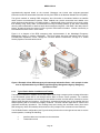
8.1.3
Typical Radio Station Installation and Testing .....................................................................................34
8.2
ALERT FM SYSTEM ............................................................................................................................................35
8.2.1
ALERT FM data input flow to the RDS encoder ....................................................................................36
8.2.2
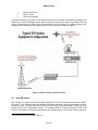
Typical radio station installation for ALERT FM ...................................................................................36
8.2.3
Programming of the RDS encoder’s Group Sequence with ALERT FM system .....................................36
8.2.3.1
8.2.3.2
8.2.3.3
8.2.3.4
Group Sequence ratios ..................................................................................................................................... 36
Alerting priorities ............................................................................................................................................. 37
Group Sequence programming example ......................................................................................................... 37
Injection levels ................................................................................................................................................. 38
8.3
NPR LABS EMERGENCY ALERTING ODA ................................................................................................................38
8.3.1
Technical overview ...............................................................................................................................39
8.3.2
The ODA in action ................................................................................................................................39
8.3.2.1
8.3.2.2
8.3.2.3
8.3.2.4
8.3.3
9
Receiver wakeup preamble .............................................................................................................................. 40
Rapid geo code sequence ................................................................................................................................ 40
Text interleave sequence ................................................................................................................................. 40
End of Transmission (EOT) marker ................................................................................................................... 40
ODA performance ................................................................................................................................41
RDS AND CHARACTER/FONT SETS ................................................................................................................ 46
9.1
OVERVIEW ......................................................................................................................................................46
9.2
DOLLAR SIGN DISPLAY PROBLEMS .........................................................................................................................46
9.2.1
Recommended actions for equipment vendors ...................................................................................47
9.2.2
Recommended actions for broadcasters .............................................................................................47
9.2.3
Recommended actions for receiver manufacturers .............................................................................48
9.3
OTHER 7-BIT CHARACTER MAP DIFFERENCES ..........................................................................................................48
9.4
SELECTED 8-BIT CHARACTER MAP DIFFERENCES .......................................................................................................48
9.5
RDS CHARACTER SET AND HD RADIO CHARACTER SET ..............................................................................................49
ANNEX 1: BROADCASTER INFORMATION ON RDS USAGE – RDS USE CASES ........................................................ 50
BROADCASTER TRAFFIC CONSORTIUM ..............................................................................................................................50
CLEAR CHANNEL MEDIA AND ENTERTAINMENT ..................................................................................................................50
COX MEDIA GROUP ......................................................................................................................................................51
ANNEX 2: RDS PROVIDERS LIST ............................................................................................................................ 53
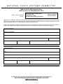
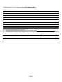
ANNEX 3: RDS PROVIDERS LIST SELF-NOTIFICATION FORM ................................................................................. 57
iv
FIGURES
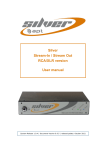
FIGURE 1. RDS ENCODER INSTALLATION – LOOP-THROUGH METHOD............................................................................................4
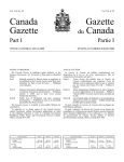
FIGURE 2. RDS ENCODER INSTALLATION – DISCRETE INPUT WITH SAMPLE OR “SIDECHAIN” METHOD ..................................................5
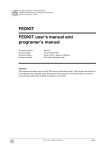
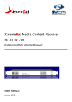
FIGURE 3. AN EXAMPLE FROM THE INOVONICS 730 USER MANUAL OF A PROPERLY SYNCHRONIZED RDS SUBCARRIER IN QUADRATURE WITH
THE PILOT, AS SHOWN FROM AN OSCILLOSCOPE ............................................................................................................... 6
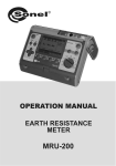
FIGURE 4. DIRECT AUTOMATION – RDS FEED ..........................................................................................................................7
FIGURE 5. LOCAL DATA MANAGEMENT ...................................................................................................................................8
FIGURE 6. SERVICE PROVIDER DATA MANAGEMENT ...................................................................................................................8
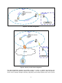
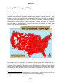
FIGURE 7. FM BROADCAST COVERAGE IN THE UNITED STATES ...................................................................................................32
FIGURE 8. EXAMPLE OF HOW RDS EMERGENCY ALERT MESSAGE INFORMATION FLOWS – THIS EXAMPLE IS TAKEN FROM AN
IMPLEMENTATION BY THE MISSISSIPPI EMERGENCY MANAGEMENT AGENCY EMERGENCY OPERATIONS CENTER........................ 34
FIGURE 9. STATION-SPECIFIC ALERTING OVERVIEW ..................................................................................................................35
FIGURE 10. NPR LABS EMERGENCY ALERTING ODA SYSTEM OVERVIEW .....................................................................................39
FIGURE 11: SYSTEM BLOCK DIAGRAM FOR MEASURING ODA PERFORMANCE METRICS ...................................................................41
TABLES
TABLE 1. MAIN FEATURE REPETITION RATES ...........................................................................................................................10
TABLE 2. LIST OF NIELSEN AUDIO FORMATS WITH SUGGESTED PTY CODES DEFINED IN NRSC-4-B ...................................................13
TABLE 3: RECOMMENDED RADIOTEXT (RT) SEND RATES FOR STATIONS WITH NO SIGNIFICANT ODA USE ...........................................24
TABLE 4. RECOMMENDED GROUP SEQUENCE PERCENTAGES FOR STATIONS WITH TMC TRAFFIC ODA USE .........................................25
TABLE 5. CHARACTER SET TRANSLATIONS FOR COMMON DOLLAR SIGN CHARACTERS.......................................................................46
TABLE 6. TEST STRINGS FOR TESTING DOLLAR SIGN BEHAVIOR ....................................................................................................47
TABLE 7. IMPORTANT SEVEN-BIT CHARACTERS THAT MAY SHOW UP INCORRECTLY ON RECEIVERS ......................................................48
TABLE 8. IMPORTANT EIGHT-BIT CHARACTERS AND THEIR RDS EQUIVALENTS ...............................................................................49
v
RDS USAGE GUIDELINE
1
SCOPE
This is an informative Guideline document which sets forth recommendations on the use of the Radio
Data System (RDS) FM data subcarrier in the U.S. for broadcasters, broadcast equipment manufacturers,
receiver manufacturers, and data service providers.
2
2.1
REFERENCES
Normative References
This is an informative specification. There are no normative references.
2.2
Informative References
The following references contain information that may be useful to those implementing this Guideline
document. At the time of publication the editions indicated were valid. All standards are subject to
revision, and users of this Guideline document are encouraged to investigate the possibility of applying
the most recent editions of the standards listed below.
[1]
[2]
[3]
[4]
[5]
[6]
[7]
[8]
[9]
[10]
[11]
NRSC-4-B United States RBDS Standard – Specification of the Radio Broadcast Data System,
National Radio Systems Committee, April 2011,
http://www.nrscstandards.org/download.asp?file=nrsc-4-B.pdf
IEC 62106/Ed.3, Specification of the Radio Data System (RDS) for VHF/FM sound broadcasting
in the frequency range from 87.5 MHz to 108.0 MHz, International Electrotechnical Commission
(IEC), Edition 3.0, 2013
NRSC-G200-A, Bandwidth Harmonization of RDS and IBOC Program Service Data (PSD)
Guideline, National Radio Systems Committee, September, 2007,
http://www.nrscstandards.org/download.asp?file=NRSC-G200-A.pdf
Coding of RadioText Plus information (RT+), RDS TS – Annex P, RDS Forum TS 2008,
R08_008_3
Radio Data System (RDS) – Receiver Products and Characteristics – Methods of Measurement,
IEC 62634/Ed.2, 2013
NRSC-R300 Program Associated Data (PAD) Field Length Study, National Radio Systems
Committee, November, 2011, http://www.nrscstandards.org/Reports/NRSC-R300.pdf
Information Technology - 8-bit single-byte coded graphic character sets - Part 1: Latin Alphabet 1,
ISO/IEC 8859-1:1998, International Organization for Standardization (ISO),
http://www.iso.org/iso/iso_catalogue/catalogue_tc/catalogue_detail.htm?csnumber=28245
Broadcaster Traffic Consortium web site, www.radiobtc.com
Total Traffic Network web site, www.totaltraffic.com
Alert FM web site, www.alertfm.com
IPAWS Radio Broadcast Data System (RBDS) Study, Federal Emergency Management Agency,
September 29, 2010, http://www.fema.gov/media-library/assets/documents/90051
1
[12]
NRSC-5-C, IBOC Digital Radio Broadcasting Standard, Reference Document 1028s rev. D
(Program service data), National Radio Systems Committee, September 2011,
http://www.nrscstandards.org/download.asp?file=NRSC-5-C.asp
NRSC-G301, Creation and Distribution Practices for Audio Program Metadata Guideline, National
Radio Systems Committee, April 2013, http://www.nrscstandards.org/download.asp?file=NRSCG301.pdf
[13]
2.3
Symbols and abbreviations
In this Guideline the following abbreviations are used:
AID
BTC
CAP
CEA
CMAS
EAN
EAS
EOT
FCC
FEMA
FM
IBOC
IPAWS
LTN
LTCC
NAB
NASBA
NRSC
NWS
ODA
PAD
PI
PICC
PRSS
PS
PSD
PTY
PTYN
RDS
RBDS
RUWG
RT
RT+
SCA
SMS
STL
TMC
UECP
VHF
WEA
Application Identification
Broadcaster Traffic Consortium
Common Alerting Protocol
Consumer Electronics Association
Commercial Mobile Alert System
Emergency Action Notification
Emergency Alert System
End of transmission
Federal Communications Commission (U.S.)
Federal Emergency Management Agency (U.S.)
Frequency Modulation
In-Band/On-Channel
Integrated Public Alert Warning System
Location Table Number
Location Table Country Code
National Association of Broadcasters
National Alliance of State Broadcasting Associations
National Radio Systems Committee
National Weather Service
Open Data Application
Program Associated Data
Program Identification
Program Identification Country Code
Public Radio Satellite System®
Program Service
Program Service Data
Program Type
Program Type Name
Radio Data System
Radio Broadcast Data System
RDS Usage Working Group
RadioText
RadioText+ ("plus"), an industry-standard ODA extension to RT
Subsidiary Communications Authority
Short Message Service
Station-Transmitter Link
Traffic Message Channel
Universal Encoder Communication Protocol
Very High Frequency
Wireless Emergency Alerts
2
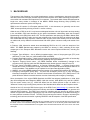
3
BACKGROUND
The purpose of this Guideline is to provide broadcasters, receiver manufacturers, data service providers
and other users with information that will help them make the best use of RDS technology and provide a
more useful and consistent RDS experience for consumers. The material which follows was discussed at
length over many months in meetings of the NRSC’s RBDS Usage Working Group (RUWG) and
represents the consensus opinion of that group.
RBDS is the US version of a European standard, RDS. In this document, we generally use the term
“RDS” unless specifically referring to the U.S. version or history.
While the use of RDS in the U.S. only became widespread with the rollout of digital radio services starting
in the mid-2000's, RDS was developed by the public broadcasters collaborating within the European
Broadcasting Union (EBU) from about 1975. The first specification was issued by the EBU in March 1984.
RDS technology take-off in radio receivers was relatively slow, as the first RDS car radios were all highend models that were fairly expensive. However within 10 years, there were already over 50 million RDS
car radios sold, and by 2004 the total had reached 200 million (these units were mostly sold outside of the
U.S.).
In February 1990, discussion started about standardizing RDS for the U.S. under the auspices of the
NRSC. The RBDS Standard was adopted by the NRSC on January 8, 1993, consisting of the major
components of the European RDS Standard but also with some important differences, including the
1
following:
● Program Type definitions – due to differing broadcast styles, some of the program type (PTY) code
definitions (i.e. Jazz, Rock, etc.) differ between RDS and RBDS;
● Program Identification coding – North American program identification (PI) codes differ in functionality
in three ranges. This affects alternate frequency switching and regionalization;
● “Dynamic” Program Service name – the RBDS Standard allows “nondistracting” changes to the
program service (PS) field, while the RDS Standard strictly forbids dynamic changes to the PS;
● ID Logic feature (IDL)/RDS updates to In Receiver Database (IRDS) – a licensed feature which
allowed the receiver to identify the call sign and format of non-RDS FM and AM broadcast stations via
a built in database. This database may be updated via an Open Data Application (ODA);
● AMRDS – the original RBDS standard reserved a section for a possible AM equivalent to FM RDS.
● Emergency Alert System (EAS) ODA – an ODA was developed ("Annex Q") to carry emergency
information compatible with the U.S. Federal Communication Commissions (FCC) EAS protocol. This
public ODA also offered increased consumer receiver functionality with emergency messaging.
Since the adoption of the original RBDS Standard, the NRSC has adopted modifications in 1998, 2004
(the official designation was changed to NRSC-4 with this version), 2005 (NRSC-4-A), and 2011 (NRSC4-B, the current version; see [1]). NRSC-4-B differs from the earlier versions in that it is written in a
"difference" format, only including those portions of the Standard which differ from the European version.
Outside of the U.S. the major RDS-focused group is the RDS Forum (www.rds.org.uk), created in 1993,
which is a non-profit international professional industry association that has the objective to promote and
maintain RDS technology. The RDS Forum serves its members and also acts as an efficient contact
network for experience exchange regarding the use and correct implementation of the RDS technology in
the many different countries involved. The RDS Forum has been the leader in Europe in advancing the
technology and has been successful in gaining CENELEC and IEC adoption of the RDS specification.
1
Note that many of these differences, including ID Logic, AM RDS, and the "Annex Q" EAS ODA were removed from
the NRSC version of the Standard starting with the NRSC-4-B version, so as to achieve greater harmonization with
the European version of the Standard and in recognition of the fact that these features were not in use or were never
developed.
3
4
4.1
RDS INSTALLATION
Hardware installation
RDS is a component of FM broadcasting that uses an encoder to create a signal which is combined with
other components of the FM baseband including the mono (L+R) and stereo multiplex (L-R) program
audio-derived signals. The RDS signal, also called the RDS subcarrier, is a 1,187.5 bits per second (bps)
data stream (with approximately 670 bps of usable data) encoded into a 4 kHz-wide suppressed-carrier
AM subcarrier centered at 57 kHz.
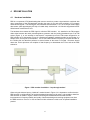
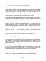
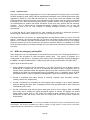
The hardware that creates the RDS signal is called an RDS encoder. It is installed in the FM program
chain either between the audio processing/stereo generator and the (analog) baseband input of an FM
exciter (Figure 1), or, the encoder is connected to a separate input on the FM exciter designed for an
RDS encoder or for subcarriers (Figure 2). Both these installation methods provide for the feeding of a
sample of the 19 kHz pilot to the encoder. The 57 kHz RDS subcarrier frequency is the third harmonic of
the 19 kHz pilot and therefore performs in similar fashion as the stereo L-R signal. Receivers should
detect the 19 kHz pilot then use multiples of that frequency to demodulate the L-R as well as the RDS
subcarrier.
Figure 1. RDS encoder installation – loop-through method
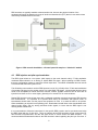
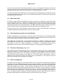
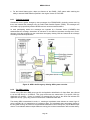
When using the discrete input or “sidechain” method shown in Figure 2, it is important to confirm that the
RDS encoder is configured NOT to feed the baseband input signal to its output. It is possible to install an
RDS encoder as shown in Figure 2 without connecting the FM baseband to the RDS encoder.
Improvements in frequency stability and quality of both transmitting and receiving equipment can allow
the RDS encoder to “free run” or use an internal 19 kHz reference but this is not an optimal installation
practice.
4
RDS encoders are typically installed at the transmitter site; however the physical location of the
equipment will largely be based on the type of studio-to-transmitter link (STL) that is in use and the data
connectivity available between the sites.
Figure 2. RDS encoder installation – discrete input with sample or “sidechain” method
4.2
RDS injection and pilot synchronization
The RDS signal exists as a low power (with respect to the main channel audio), 57 kHz amplitudemodulated data subcarrier on an analog or hybrid IBOC FM signal. When installing an RDS encoder,
there are configuration options to control the overall output level. The NRSC-4 Standard does not include
a recommended subcarrier injection level.
This Guideline recommends a nominal RDS injection level of 6% (4.5 kHz) of the 75 kHz total modulation
of an analog FM signal (or the analog portion of a hybrid IBOC FM signal). Values below this have been
found to be acceptable for mobile receivers; however, smaller, portable receivers tend to work with an
injection level closer to 6% or even higher, generally not to exceed 7% for most conditions.
Setting RDS injection levels is best done with a calibrated modulation monitor that supports RDS injection
level measurement. It is important to be precise about setting of modulation and injection levels, so
broadcasters should make sure the proper test equipment is used. It is worth the effort to be precise.
When establishing an injection level operating point, broadcasters should listen to the demodulated mainchannel audio signal, and any analog subcarrier audio signals, to insure that the RDS signal is not
causing audible interference.
It is recommended to follow the instructions for the specific RDS encoder used to synchronize and align
the RDS signal with the 19 kHz pilot. There are stations where RDS encoders are not synchronized or
have become unsynchronized, and this has been known to cause issues with RDS reception. It is
recommended that broadcasters observe the RDS encoder’s status regarding the pilot sync over time. If
5
the 19 kHz pilot sample into the encoder is marginal, there have been situations where an encoder was
going in and out of sync as a result. When an encoder is going in and out of sync, it can cause RDS
reception errors, thus creating a bad end-user experience by delaying the decoding of the RT and
skipping of PS frames.
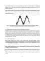
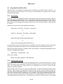
Another added benefit of going through the RDS encoder manufacturer’s synchronization process
besides better RDS performance at the receiver is that a properly synced RDS encoder will utilize a
subcarrier signal that is in quadrature with the 19 kHz pilot; this will slightly reduce the modulation peaks
of the subcarrier without reducing their actual levels, providing for more room for the main channel
modulation (see Figure 3).
Figure 3. An example from the Inovonics 730 user manual of a properly synchronized RDS
subcarrier in quadrature with the pilot, as shown from an oscilloscope
4.3
RDS Injection for stations with 67 kHz analog subcarriers
4.4
Initial programming
Stations that utilize 67 kHz analog subcarrier need to be aware that higher injection levels may result in
increased crosstalk from RDS into the 67 kHz subcarrier audio. A study was done in 2002 by Modulation
Sciences (under a contract with Minnesota Radio Talking Book) to test a wide variety of 67 and 92 kHz
analog subcarrier receivers and how their performance was impacted by RDS and multipath interference.
The RDS tests were done using two levels of RDS injection, 11.1% and 16%. It was found that the
11.1% injection level operation increased crosstalk into virtually all of the 67 kHz analog subcarrier
receivers tested, from 7 to 20 dB.
RDS encoders typically have on-board memory which allows configuration settings, encoder
programming and certain other data to be saved on-board. In locations where data connectivity is difficult
or impossible, stations should use this on-board memory to take advantage of RDS features and even
create a scrolling display of messages.
Certain RDS data, like PI, PTY, TP, AF and M/S are programmed into the encoder during installation,
even if the station is using a live data feed. In older encoders this data may need to be factory-encoded
using firmware although most encoders now allow changes to be made in the field using a computer and
a serial or IP connection to the device.
Many RDS encoders allow RadioText (RT) messages to be loaded into memory, allowing FM stations to
send data for display on RDS receivers, even if the station is not able to send live now-playing or program
associated data. Many encoders even allow such messages to be scheduled so that, for example a
different message could be scrolled during each program or could be used to identify the scheduled onair talent.
6
4.5
Data Feeds
Most RDS encoders provide a means to send live data to the RDS encoder. This is achieved using either
a serial data connection or an Internet protocol (IP) connection. Since the bandwidth of the entire RDS bit
stream is only 1,187.5 bits per second, integrating the data into a station STL or transmitter site data
connection will not require significant overhead. Typically stations feed live data using a data source like
the radio automation playback system. Many radio automation providers can export live data based on
the on-air programming and export this data to RDS encoders either as a function of the base automation
system or as an extra option. Automation equipment manufacturers and RDS equipment suppliers
should be able to provide guidance on appropriate means to interconnect the equipment.
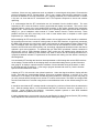
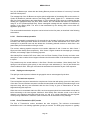
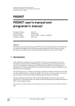
Figure 4. Direct automation – RDS feed
The basic connection is illustrated in Figure 4 which illustrates a data feed from a station automation
directly to the RDS encoder. Most automation systems can provide this using either an RS-232 Serial
connection or using TCP/IP. The RDS encoder will be programmed with static parameters such as PI and
repetition rate. Live data will typically appear as RT and/or a scrolling PS display.
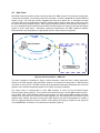
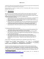
The native mode of communication of most RDS encoders is known as the Universal Encoder
Communication Protocol (UECP). This is still the most effective means to access RDS features like RT+,
song tagging, TMC (Traffic Message Channel) data, paging, etc. Most popular RDS encoders also offer
access to RT and other more common live data features to be sent using ASCII (ISO 8859-1) format
character data. Stations that wish to exploit more RDS features may find it advantageous to employ a
device to aggregate data and convert it to UECP. This could be done using a computer on-site (Figure 5)
or by establishing a connection to an outside service provider (Figure 6).
7
Figure 5. Local data management
Figure 6. Service provider data management
The data management computer can provide a means to “scrub” or “sanitize” the feed from the
automation system and optimize the data for RDS displays. The local computer or offsite data provider
can be used to manage message scheduling, dayparting, and message repetition rates; and to provide
8
access to RDS features like RT+. Outside data broadcasting providers can also provide a means to
incorporate special features such as Apple iTunes song tagging, and news or traffic data.
When stations use a live data feed, special arrangements will be required to accommodate long form
programming, live programming, and network feeds. During these periods most station automation
systems will not be sending new data to the encoder so an RDS display will show the last live event,
(e.g., the last song played before a pre-recorded talk show or network program). During these
circumstances the integrated message scheduling features of some RDS encoders can be used or an
intermediate device, a service provider, or even a network data feed could be used to provide the relevant
messages.
It should be noted that the NRSC has developed a guideline, NRSC-G301, which provides a data
standard/framework which supports live or network programming feeds to communicate to the automation
system the relevant program content [13]. For example, a syndicated music show from a network provider
could publish the programs content (song title/artist) that the automation playback system could then
export to the RDS encoder as if it were playing the music locally.
There are a number of data service providers that may offer hardware and services to manage RDS data.
Each supplier will have individual requirements and capabilities that will have an impact on the data paths
as displayed above. A reference list of providers appears in ANNEX 2: RDS Providers List.
9
5
SELECT FEATURES OF RDS
While the RDS Standard provides for a host of features, there are some features that are more widely
used than others. Discussed in this section are details about and considerations regarding usage of some
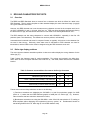
of the most frequently used RDS features. Most of those features are included in Table 1 (taken from the
NRSC-4-B standard).
Table 1. Main feature repetition rates
5.1
2
Program Identification (PI)
The original purpose of the PI code was to identify the station in a unique way. NRSC-4-B stipulates the
method for calculating the appropriate PI code, to generate a hexadecimal number that would be entered
into the encoder. There are a few software utilities available that will convert the station call letters to the
4-digit hex PI code. Most RDS encoder manufacturers should be able to provide information on this
calculation.
Those interested in implementing PI code translation on the receiver side need to be aware that there are
two PI code encoding methods used by broadcasters in the US
“Call letter conversion” encoding method, as described in NRSC-4-B Section D.7.1; and
An optional method for use with traffic information systems, as described in NRSC-4-B Section
D.7.4.
As a result of the popularity of the second method, there are stations that do not send call letters through
PI codes. In other words, the receiver cannot rely on PI codes to provide call letters for U.S. broadcast
2
NRSC-4-B [1], Table 4.
10
stations. For this reason, it is recommended that receiver manufacturers decode the RadioText Plus
(RT+) StationName.Short field in place of back-calculating the call sign using PI codes.
Besides situations where the method described in NRSC-4-B Section D7.4 is used, there may be other
cases where stations are not able to use a PI code derived from call letters. In such cases, an
appropriate PI code must be assigned. Original PI code creation may need to follow to station or
company agreements, or may need to follow additional technical requirements.
For example, if an FM station uses translators and boosters and that station employs the Alternate
Frequency (AF) capabilities of RDS, then RDS encoders at the booster and translator sites would send
the same PI code as the main station transmitter and not the PI codes corresponding to the particular
booster's and/or translator's call signs. A receiver with the ability to use the AF feature would then be
able to recognize that the booster or translator was the appropriate alternate signal because of the
matching PI codes. This is an RDS capability that is used more commonly in Europe but has not been
used widely in the U.S to date.
5.1.1
Designing the appropriate Program Identification (PI) code for boosters, translators, and
simulcasts
Increasingly, FM translators are used for cross-service stations (AM, FM hybrid IBOC multicast channels,
etc.). In such cases, PI code selection or creation may not be obvious. The following section provides
some guidance for PI code selection in these cases.
For stations which follow the following conditions:
1) Translator or booster carrying primary stations’ FM analog/IBOC main channel;
2) Translator carrying FM hybrid IBOC multicast of primary station which is simulcast of an AM with
unique call letters for market;
3) Main FM station or translator programming of an in-market AM with unique call letters.
The NRSC recommends using the PI code calculated from the call sign of the primary AM or FM station
originating programming, as defined in Section D.7.1 of NRSC-4-B.
For stations which exhibit any of the following conditions:
4) Translator carrying FM hybrid IBOC multicast channel of a primary station that is a simulcast of
an in-market AM with non-unique call letters (i.e., the primary is WXXX-FM but is a simulcast of
AM station WXXX);
5) Main FM station or translator carrying programming of an in-market AM with non-unique call
letters (the AM is WXXX, but there is already an WXXX-FM that is not the main FM station or
translator under consideration);
6) Translator carrying the FM hybrid IBOC multicast channel of a primary station which is a unique
program non-associated with any existing station.
Under conditions 4) through 6) above, the NRSC recommends carefully selecting another call sign from
the RDS PI code space outlined in [1] Table D.7 (page 20 only) using the following guidelines:
a) Avoid using a PI code based on a call sign assigned by the FCC to another station in the U.S. By
exception, if desired, the stations listed in conditions 4) through 6) above may consider swapping
the "W" or "K" prefix of the call sign with a "K" or "W" respectively, if such a swap will not cause
confusion with a station licensed to that call sign in that market or nearby markets.
11
For example, an FM translator of AM station WSEN in Syracuse would consider transmitting a PI
code "KSEN" to avoid duplicating the WSEN-FM PI code while retaining the last three characters.
The real KSEN AM and FM stations are some 2000 miles away. This is the only method by which
the NRSC recommends choosing a PI code that represents a call sign in use by another station
under conditions 4) through 6) above.
b) If desired, the stations listed in conditions 4) through 6) above may consider using an unassigned
call sign by referring to the FCC database. At any given time, there are more four-letter call signs
not assigned to AM and FM stations than are assigned. If at some time in the future a station or
stations using an unassigned call sign to generate a locally unique PI code learns that the call
sign is no longer unassigned, the station or stations should select a new unassigned call sign to
generate a new locally unique PI code.
Broadcasters and receiver manufacturers are discouraged from relying on generation of call signs from PI
codes for station identification to listeners for the reasons given in Section 5.1 and are encouraged to rely
on other methods outlined in NRSC-4-B and discussed in this Guideline to identify stations on user
displays (i.e., RT+ StationName.Short). Broadcasters are expected to verify they have not selected a
duplicate PI code that another broadcaster has selected. This is best done by calling or meeting with
other broadcasters in the local area.
5.2
Program Type (PTY)
The PTY code should be used as a format description for the station. Receivers that fully support PTY
use the code to categorize stations and provide ways for listeners to search for radio programming. It’s
not unusual for stations to choose a PTY code that doesn’t strictly adhere to their format definition. The
PTY code will often more closely match a marketing position or public image, as opposed to a strict,
industry definition of the station’s format.
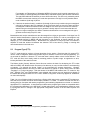
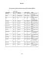
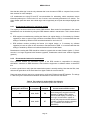
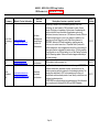
The Nielsen Audio (formerly Arbitron) format list was used as the basis for developing the PTY codes
defined in NRSC-4-B. Nielsen Audio uses terms of art that may or may not reflect listener’s understanding
or listening. For example the format “Urban” is not necessarily an accurate description. Likewise,
Spanish-formatted stations will likely not want their stations to appear on public radios under the label
“Language” or “Foreign Language.” With the release of the NRSC-4-B standard, the PTY codes for “Hip
Hop”, “Spanish Talk”, and “Spanish Music” were adopted and receivers are now beginning to appear on
the market that recognize these new PTY codes. Stations using these codes may appear as “Undefined”
on older radio displays.
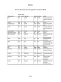
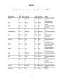
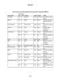
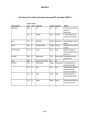
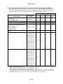
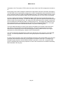
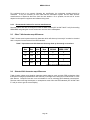
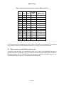
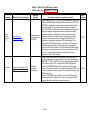
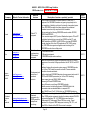
Table 2 is a list of Nielsen Audio formats (from a Spring 2013 listing) with a suggested PTY assignment.
Note that some formats are shown with multiple possible PTY codes. It’s best to consider this list as a
starting place for discussion with station programming and marketing departments to decide on a station's
appropriate PTY classification. It should also be noted that the program types listed are compatible within
the corresponding definitions in the HD Radio™ digital radio system, and considerations should be made
to synchronize the PTY settings in the appropriate configuration sections of an HD Radio Importer and
3
Exporter.
3
See pg. 59 of [12] for a list of genres supported by the NRSC-5-C Standard.
12
NRSC-G300-A
Table 2. List of Nielsen Audio formats with suggested PTY codes defined in NRSC-4-B
Page 13
NRSC-G300-A
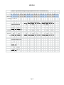
Table 2 (continued). List of Nielsen Audio formats with suggested PTY codes defined in NRSC-4-B
Page 14
NRSC-G300-A
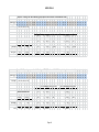
Table 2 (continued). List of Nielsen Audio formats with suggested PTY codes defined in NRSC-4-B
Page 15
NRSC-G300-A
Table 2 (continued). List of Nielsen Audio formats with suggested PTY codes defined in NRSC-4-B
Page 16
NRSC-G300-A
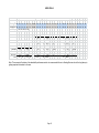
Table 2 (continued). List of Nielsen Audio formats with suggested PTY codes defined in NRSC-4-B
Page 17
NRSC-G300-A
5.3
Program Type Name (PTYN) codes
While PTYN is part of the European RDS Standard, the NRSC believes it is not commonly used in
receivers designed for the U.S. Given the finite bandwidth available for RDS applications, it is
recommended to not encode PTYN and instead use the available bandwidth for more useful features like
RT+ song tagging, and for increasing RT transmission rates which can be of benefit to a large number of
receivers.
5.4
Traffic programming (TP)/Traffic Announcement (TA) flags
While stations are encouraged to encode the Traffic Programming (TP) flag if they provide traffic reports,
and receiver manufacturers are encouraged to display that information, automatic receiver switching
using the Traffic Announcement (TA) flag is discouraged. The NRSC understands that there have been
complaints and confusion from listeners when the TA flag has been used to automatically switch a
receiver.
Since the development of the TP/TA feature set in RDS, more efficient and advanced traffic reporting
features have been made available to the general public. Instances of these include Global Position
Systems (GPS) navigation devices with embedded FM or HD Radio receivers that can decode traffic
incident data and display it on a map and provide re-routing assistance. Also, out-of-band data provided
on the Internet and viewed on smartphones provides another way in which to convey this information to
the public.
5.5
Music/Speech (MS)
Stations are encouraged to set this switch appropriately according to the programming being broadcast. A
value of 0 indicates speech is present and a value of 1 indicates that music is present.
5.6
Decoder Identification and Dynamic PTY indicator (DI)
These bits indicate audio modes that are appropriate for use with the broadcast and to indicate if PTY
codes are being switched dynamically. Typically in the U.S. a value of 0 on bit d0 is used if the audio on
the station is monaural, and a value of 1 is used if the station’s audio is in stereo.
5.7
Alternative Frequency (AF)
AF is frequently implemented in Europe but AF has not been a widely used feature in the U.S. AF is
primarily intended to enable receivers to find simulcast stations automatically. The PI code still controls
whether a receiver will automatically switch. The PI code is the broadcaster’s indication that the receiver
should automatically switch, if this feature is enabled on the receiver. The same PI code transmitted on
multiple stations means identical audio program content is being broadcast on those frequencies. RDS
encoders are programmed to transmit a list of frequencies directing a compatible receiver where to
receive the same programming. Its intended application in the U.S. would be to associate fill-in
translators and boosters, or full service FM stations that fully simulcast another station in the area. AFcompatible receivers should verify that the station on the alternate frequency is transmitting the identical
PI code as the current station and should not switch if the code is not the same.
It is important to stipulate that the purpose of the AF feature is not to control receivers in such a way that
the equipment will switch between co-owned full-service FM stations that broadcast different content, or
to link stations airing similar but not identical programming. The program content should be identical (i.e.,
simulcast) between the AF frequencies. Stations should consider carefully the listener experience when
Page 18
NRSC-G300-A
employing AF and ensure that the associated signals are transmitting the identical programming and to
limit the time offset (delay) of simultaneous programming to under 1-2 seconds.
Stations that implement AF to link full-service, booster, or translator stations must not only set the list of
alternative frequencies into the primary station’s encoder but should also program complimentary values
into encoders feeding all associated stations. Stations that choose to implement AF to link stations that
air common programming only during certain times should not publish on any of the stations' encoders
any AF channel numbers that refer to stations whose programming is not currently identical. If there are
no stations whose programming is currently identical, then the AF list should be deactivated until such
time as another station is again transmitting identical programming.
The European standard specifies two methods to transmit AF lists. The methods are called A and B. In
the U.S., only method A is used. Method A can carry up to 25 alternative frequencies for an identical
program. Information about this method is contained in IEC 62106 [2] beginning in Sections 6.2.1.6.2 and
6.2.1.6.3.
If a station is not explicitly using the AF feature it is recommended that the AF list be empty.
5.8
Clock Time (CT) Group
This group is sometimes sent if a station is sending a time/clock and date reference. To conserve
bandwidth, a single 4A group packet is sent every sixty seconds. If a station is not explicitly using this
feature it is recommended that the group not be sent. For stations electing to send the 4A CT group,
ensure that the RDS encoder is properly and continuously time synced to a reliable external time source.
Also be sure that the CT local offset is correctly set to the local time zone. These offsets must also be
adjusted in accordance with Daylight Saving Time changes. Stations transmitting inaccurate time or that
have improper local CT offset settings can cause issues with receivers that use the CT to display time.
Information about CT is contained in the IEC 62106 [2] beginning in Section 6.1.5.6.
Page 19
NRSC-G300-A
6
6.1
USING RDS FOR PROGRAM ASSOCIATED DATA
Overview
Program Associated Data (PAD) is a term used to describe data (usually textual) that is associated with
an audio program on the radio. PAD can vary depending on the type of material being aired on the radio
station. The most common use of PAD currently via RDS is the current song title and artist data.
However, there are many other types of PAD that can be encoded via RDS and displayed such as the
song’s album data, or in the case of non-music related programs, more information about the program.
For example, a radio station running a live talk show may include the show’s name, topic being
discussed, the name of the guests and, perhaps the phone number to call in and participate in the show.
The examples above are just some of the current and potential uses of PAD for RDS.
The importance of transmitting PAD data via RDS cannot be overstated. Broadcasters need to present a
consistent user experience to listeners across all stations in a given market. When only a few stations in
a market are transmitting PAD then this puts radio at a competitive disadvantage compared to other audio
services, in particular Satellite Digital Audio Radio Service (SDARS) and Internet based streaming audio
services that consistently provide PAD. The NRSC recommends that each and every station implement
dynamic PAD over RDS.
Increasingly, more radios are being sold that include RDS including smartphones with FM radio
capability. As these radios continue to be adopted by consumers; it is vital that broadcasters provide
information to the listener about the current programming on the air. The ability to make this information
available to the receiver display keeps terrestrial radio relevant with other forms of technology, such as
portable music MP3 players, satellite radios, and Internet streaming audio applications via a computer,
portable device or phone. For those stations also employing hybrid IBOC transmissions (both AM and
FM), many of the concepts here also apply to the HD Radio system's Program Service Data (PSD)
capability and can result in an overall improvement of PAD/PSD implementation across multiple
platforms.
As outlined below, it is recommended that stations encode PAD in the RadioText (RT) field, and
optionally in the Program Service (PS) field, as described in Sections 6.8 and 6.9 below.
6.2
Receiver display length considerations
For guidance on receiver alpha-numeric display length, and information on how many characters are
required to display artist and title information over a typical over-the-air broadcast RDS data stream,
receiver manufacturers are encouraged to consult the companion document to this Guideline, NRSCR300. NRSC-R300 is entitled Program Associated Data (PAD) Field Length Study. [6] This report
provides valuable information on song title, artist and album usage to help guide decisions when
designing receiver displays.
6.3
Confusion between PS and RT
PS and RT are different fields in the RDS Standard and can be treated differently by each receiver. While
the general listening public does not necessarily need to know what they are looking at (PS or RT), radio
stations encoding RDS should understand how both fields relate to the end-user experience.
It is important to know that there are newer radios that support RT equally, if not better than they do PS.
These new receivers display the RT in a more prominent manner. While so much of the emphasis in the
past within the U.S. has been on the dynamic PS and its scrolling/framing effects, broadcasters need to
be equally as aware of RT. Ignoring RT is ignoring the end-user experience that listeners on the newer
devices now have, and this could be detrimental to the future of RDS-enabled radio displays.
Page 20
NRSC-G300-A
Given that many feature-rich hand-held and portable receivers and advanced automotive receivers are
already on the market, the future should bring more receivers that display RT in a prominent way, and the
broadcast industry needs to make sure as much value is being placed on RT as on PS.
The NRSC has noted some stations that are doing dynamic PS scrolling/framing for PAD data, but are
not transmitting PAD data in the RT field. It is recommended that stations in this situation should transmit
PAD data in the RT field as well.
6.4
Album name data
All stations encoding RDS and supporting song title and artist are encouraged to transmit the album
name (if applicable) using RT. Satellite radio, digital cable radio and Internet streaming stations often
include the album name of the song they are currently playing. Many of the radio industry’s web-sites
and streaming initiatives show album name data. With RDS, broadcasters have the ability to provide the
same information about the songs playing and achieve parity with other competing mediums.
It should be noted, due to space limitations, that the inclusion of album name information in the shorter,
scrolling/framing/dynamic implementations of PS is not recommended.
6.5
Data formatting, truncation, and capitalization
Similarly, broadcasters are encouraged to review the quality of the data they are transmitting via RDS.
Look for music libraries that have truncated, incomplete or inaccurate title/artist/album data. Stations may
need to “groom” the music libraries to make sure the data is accurate.
When RDS was first implemented, it was the general consensus to capitalize everything sent because
some radios did not support lower case characters. The majority of receivers in use today do not have
this problem, so the use of proper capitalization is encouraged. If capitalization beyond what is
grammatically correct must be used, the recommendation is to use it sparingly (and appropriately).
6.6
Extra text (“Now playing…by…on”)
Some stations add the phrases “Now playing”, then insert the title of the song, then “by” followed by the
artist name, and then “on” and the station name. This practice is discouraged as discussed in NRSCR300 (reference [6], pages 18-19). This extra text will lengthen the time it takes for a driver to observe the
real information being conveyed on the display (i.e., Title, Artist, Album). “Now playing ” adds 12
characters to the required text length, and removes the key information (i.e. the Title) from the prime
location (the beginning of the text string on the display).
6.7
Data and song timing
For stations that are running an audio delay, whether it be for purposes of synchronizing analog and
digital audio in a hybrid IBOC transmissions, and/or for profanity deletion, it is strongly recommended that
adjustments be made in the RDS PAD data transmission delay so that the audio and corresponding PAD
are properly aligned at the receiver. Some hardware and software products on the market have this
ability, and it is best to research this and spend some time “fine tuning” it. If this is ignored, it is possible
that a song’s PAD could show up before the song is on the air. When transitioning into another song, the
new song’s data can be displayed for a period of time while the old song is still playing, which is also an
issue. For stations running in real-time (no delay) this alignment process is likely to be less of a factor, as
the data is likely being sent to the RDS encoder at the same time the song is changed.
Page 21
NRSC-G300-A
6.8
Using RadioText (RT) for PAD
RadioText (RT) is a 64-character field which can be transmitted via an RDS encoder to receivers. As
mentioned above, the PAD content of the RT field can vary depending on the program that is currently
airing on the radio station.
6.8.1
RT formatting
In the case of music, it is suggested to have the radio station’s name, along with the song’s title, artist and
album information (if applicable) sent via RT. A separator between each of the fields is recommended, to
give better readability for the listener. In the example below, a single hyphen character is used, - (ASCII
Decimal 45, Hex 2D), although other delimiters could be used, such as a foreword slash, / (ASCII Decimal
47, Hex 2F).
Uses may vary, but here are some suggested combinations:
Station Name – Song Title – Song Artist – Song Album
or
Song Title – Song Artist – Song Album – Station Name
or
Station Name Song Title/Song Artist/Song Album
or
Song Title/Song Artist/Song Album Station Name
In some cases the song’s album information is not available. This can be omitted, however, if the means
to provide this information are available, it is recommended that album information should be listed.
National Public Radio (NPR) has conducted studies that indicate for informational/topical/spoken word
formats, the suggested text might be:
Station Name – Program Name – Topic
Using a “live” example:
WZZZ – All Things Considered – Deficit Reduction
6.8.2
RadioText (RT) send rate
As discussed earlier, many newer receivers are displaying the RT in a more prominent manner. Almost
every RDS encoder has an adjustment controlling how frequently the RT is sent compared to other data
fields. The default settings of existing units are not necessarily set the best for a good end-user
experience and require attention.
When an RDS receiver first tunes to a station with RDS and RT, it locates the RDS data signal and starts
decoding. Many receivers are designed to wait until the RT has been sent twice before displaying to
make sure it was received without any errors. If RT is not being sent frequently, this can take some time
and result in excessive delay for displaying of RT information. RDS encoder defaults typically have a
very slow RT send rate setting. Many encoders dedicate 75% of the bandwidth to the PS and 25% to RT.
These default settings could take up to 15 seconds for the receiver to decode the RT under optimal
Page 22
NRSC-G300-A
conditions. If there are any impairments such as multipath or a weak signal during those 15 seconds the
process of displaying the RT can take longer. This, in turn, creates a bad end user experience. Couple
this with the addition of the new RadioText+ (RT+) tagging standards (to be discussed later in Section
6.10) and it is clear that the RT transmission rate is an important component to check and consider
optimizing.
It is recommended that the RT transmission rate be increased from the default values. The more
frequently the RT is sent, the faster a receiver can decode and display it to listeners. This is even more
important when it comes to the new portable RDS receivers on the market, because they prominently
display the RT. These receivers are also more likely to be operating at lower signal levels due to antenna
design (i.e., just a headphone cable instead of a better antenna found in mobile receivers). These
portable receivers are also more likely to be used in areas where there is multipath or other signal
impairments (i.e., inside buildings).
Before adjusting the RT send rate on the RDS encoder, the consequences of this should be considered.
By increasing the send rate, a trade-off is being made on other RDS functions. As previously mentioned,
the RDS signal operates at a low bit rate, with a useful capacity of approximately 670 bps. When the RT
rate is increased, other data types may suffer as fewer bits will be available for these functions. For
instance, the PS will be sent less frequently, and, accordingly, adjustments should be made to that field to
maintain a good user experience. For stations that use other RDS “specialized” features contained in
ODA groups, such as Traffic Message Channel (TMC), make sure the settings being changed do not
impact these services. Stations in this situation may need to reduce their RT sending rates down as a
compromise between a better RT experiences for the listener and making sure the station is meeting its
ODA obligations.
A recommended RT sending rate has been developed based on field testing with various RDS receivers
on the market. The benchmark for developing these recommended settings was to get the information
sent using RT to display in optimal reception conditions 3-4 seconds after tuning to the station, or after
the RT data had been changed (i.e., a new song or program element had come on). See the encoderspecific recommendations in Table 3.
A display of RT in 3-4 seconds is the optimal experience. Under bad signal conditions, display will take
longer. Even with the recommended settings, under poor reception conditions, it can take 10 or more
seconds for RT to display. If the RDS encoder has factory default RT send rates a receiver may take 30
(or more) seconds and/or perhaps never resolve RT in these environments. The NRSC encourages RDS
encoder manufacturers to consider using these recommendations below as the default settings for new
units.
It should be noted that the RT message should not change for a minimum of three times the transmission
time. With the settings below, it is recommended that the RT remain the same for a minimum of 15
seconds. Longer durations are preferred. Automation playback systems or other RDS metadata
solutions should not update the RT too often.
If making adjustments to your encoder, be sure to read Section 6.9 about Program Service (PS) scrolling
delay adjustments that should also be considered when making this change.
Page 23
NRSC-G300-A
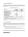
Table 3: Recommended RadioText (RT) send rates for stations with no significant ODA use
Note: these settings may interfere with any special ODA groups being transmitting such as leased traffic or
other data. When transmitting ODA data, it is best to consult with the station’s corporate engineering staff or
the company that is leasing the data to ensure there is no interference with these services.
RDS group type / feature
0A PS
(%)
2A RT
(%)
3A
(%)
RT+ ODA
(%)
RT_RATE=1
45
50
1
4
†
DRTS=9
63
32
1
4
Inovonics 720, 730 *
DRTS=9
24
71
1
4
GS=0A,2A,2A,2A
24
71
1
4
GRPSEQ=0222
24
71
1
4
25
69
1
5
Recommended
Setting
Encoder Type(s)
Inovonics 711
†
Audemat FMB1, FMB10
Inovonics 712, 713
Audemat (Worldcast) FMB-50, FMB-80
†
Burk RDS Master
††
BW Broadcast RDS3
††
Kvarta RDS1000
Pira32
††
††
DEVA SmartGen Mini, 4.1, 5.0
††
SQC=2A, 2A, 2A, 0A,
2A, 2A, 2A, 0A, 2A,
2A, 2A, 0A, 2A, 2A,
2A, 0A, 11A, 2A, 2A,
0A, 2A, 2A, 2A, 0A,
2A, 2A, 2A, 0A, 2A,
2A, 2A, 0A, 2A, 2A,
2A, 0A, 11A, 2A, 2A,
0A, 2A, 2A, 0A, 2A,
2A, 2A, 0A, 2A, 2A,
2A, 0A, 2A, 2A, 2A,
0A, 2A, 2A, 2A, 0A,
11A, 2A, 2A, 0A, 3A
2wcom C02, C04
†††
2A, 2A, 2A, 0A, 2A,
2A, 2A, 0A, 2A, 2A,
2A, 0A, 2A, 2A, 2A,
0A, 11A, 2A, 2A, 0A,
2A, 2A, 2A, 0A, 2A,
2A, 2A, 0A, 2A, 2A,
25
69
1
5
2A, 0A, 2A, 2A, 2A,
0A, 11A, 2A, 2A, 0A,
2A, 2A, 0A, 2A, 2A,
2A, 0A, 2A, 2A, 2A,
0A, 2A, 2A, 2A, 0A,
2A, 2A, 2A, 0A, 11A,
2A, 2A, 0A, 3A
†
Many legacy encoders do not support integrated RT+ from the manufacturer, but 3rd party hardware or software
solutions exist to enable these features.
* Requires firmware upgrade of 2.6 or higher to achieve desired group sequence.
††
May require firmware or software upgrade to enable integrated RT+ features.
†††
Requires ARCOS configuration software. Encoder -> Dataset -> General -> Group Sequence. GS= string, not required.
Replace 11A with desired RT+ ODA location. Encoder needs RT+ AID configured and 3A and RT+ ODA specifically
shown in Group Sequence and AUTO_RTPLUS enabled to use integrated RT+ transmission feature.
Page 24
NRSC-G300-A
Table 4. Recommended group sequence percentages for stations with TMC Traffic ODA use
Note: These group sequencing benchmarks are suggested for stations running Traffic Messaging Channel
(TMC). Generally, TMC requires 25% of RDS bandwidth to be allocated to its specific ODA. Specific
providers will likely have a customized group sequence setting specific to their service and encoders. The
NRSC encourages TMC providers to provide optimized group sequencing for RT 2A transmission.
RDS group type / feature
6.8.3
0A PS
(%)
2A RT
(%)
8A TMC
(%)
3A
(%)
RT+ ODA
(%)
24
45
25
2
4
RT length padding
To combat display problems on legacy receivers, some RDS encoders give the option to always send 64
characters in RT. If enabled, when the encoder sends something under 64 characters, it adds spaces to
the RT data so as to always transmit 64 characters. It is believed that few, if any, receivers still need this
option. For encoders with this ability, it is recommended that this padding feature be turned off.
The longer the RT is, the longer it takes to transmit. By always transmitting 64 characters, there will
always be the maximum delay. Most receivers do not display the RT data until it has been fully received
without errors twice. The process of displaying RT data to the receiver is being slowed down
unnecessarily in many cases. Look for settings related to short RT versus long RT. Unfortunately, with
some legacy encoders, this option cannot be turned off.
6.9
Using scrolling Program Service (PS) for PAD
NRSC-4-B does not support using the Program Service (PS) field for PAD, as it is a single, static 8
character field. However, use of a “dynamic,” “framing,” or “scrolling” PS is a common practice within the
U.S. Provided here is some best practice information for those stations that elect to provide PAD data via
dynamic PS.
The PS is an 8-character field that was designed to describe the radio station and remain static (i.e.,
never change or change only intermittently). Many of the early RDS receivers displayed only this field
prominently on the display. Over time, the use of the PS has evolved into a dynamic (i.e., changing)
“scrolling” or “framed” display. Many stations in the U.S. frequently change what is in this PS field to
interleave (or scroll) not only the station name but song artist, title, advertisements, promotional and other
messages.
Because there is a limitation of 8 characters in this field, many of the messages stations want to display
do not fit. RDS hardware and software vendors have developed solutions to take a long string of
characters and put it into the PS field 8 characters at a time, with a delay in between, creating a “scrolling”
or “framing” effect. The interval between these frames is the PS scroll delay. This delay is an adjustable
setting in most RDS hardware and/or software products. It should be clear, in this specific section, that
this delay is the time a particular 8 character PS field remains unchanged, and not the number of
individual 0A PS packets that are sent out during this time. This could also be described as the PS field
change rate.
Stations with low PS field change rates may have found the radio receiver dropping the 8 character PS
frames periodically. It has been found that many stations have this scrolling delay set too low (i.e., not
enough delay) and when the receiver has impairments (such as multipath) the PS frames drop. With
RDS encoder defaults, stations running a delay on their PS at under 2.0 (two) seconds were already
prone to this.
Page 25
NRSC-G300-A
In addition, because PS was originally intended to be ‘static’ some receivers interpret a changing PS to
be a fault and suppress any PS display until at least three receptions of the same text have been
received.
When the recommendations above in Table 3 and
Page 26
NRSC-G300-A
Table 4 for an aggressive RT send rate are followed, then the receivers that prominently display the PS
may start dropping frames, even under optimal conditions. Again, this is due to the data rate limitations of
the RDS signal. Given this, a minimum delay of 4 seconds between PS frames is recommended. For
more multipath-prone stations, or for stations that have chosen to have their RDS subcarrier injection
level below 6% (4.5 kHz), this could be set closer to 5 seconds to improve PS performance.
6.9.1
PS formatting
In the case of music, it is suggested to have the radio station’s name, along with the song’s title, and artist
information. Because of the limited amount of characters in the PS field, sending the song’s album
information via the PS field is not recommended.
Uses may vary, but here are some suggested combinations:
Stat ion Na me So ng Tit le Son g A rt is t
Using a “live” example:
WZZZ Fi ref lie s Ow l Ci ty
This would be broken up into several PS frames, which will be changed after the PS delay:
WZZZ
Fire fli e
iref lie s
Owl
City
Note, in the example above, the song title “Fireflies” has a length of 9 characters. The PS only supports 8
characters, so a framing technique has been employed.
National Public Radio (NPR) has conducted studies that indicate for informational/topical/spoken word
formats, a suggested text might be:
Stat ion Na me Pr og ram Nam e T opi c
Using a “live” example:
WZZZ Al l T hin gs C onsi der ed Def ic it Red uct ion
This would be broken up into several PS frames, which will be changed after the PS delay:
WZZZ
All
Thin gs
Cons ide r
nsid ere d
Defi cit
Redu cti o
educ tio n
Note, in the example above the word “Considered” has a length of 10 characters, and “Reduction” has a
length of 9 characters. The PS only supports 8 characters, so a framing technique has been employed.
Page 27
NRSC-G300-A
6.10 Using RadioText+ (RT+) for PAD
In Section 6.3 above, the importance of implementing PAD data within the RT field was stressed.
Broadcasters are also encouraged to adopt the RadioText+ (RT+) tagging standard for PAD data in the
RT field. [4]
RT+ is an additional ODA data stream defined in IEC 62106 Annex P that can be added to an RDS
stream, identifying the text being encoded in the RT field. Until the RT+ Standard was developed, there
was no way to know what the specific parts of the RT data were, from a hardware or software standpoint,
and this is important for song tagging. RT+ offers the ability to classify different types of information (such
as title) and their location within the RT field.
Because the RT field is so flexible, the receiver cannot make any assumptions as to what information is
contained within, but RT+ bridges the gap and essentially allows for definition of what each part of the RT
actually is. It also gives radio stations an “MP3 player feel” by making it possible to consistently show
title, artist, and album on separate, defined areas of the display. That in turn makes for better readability
for the listener.
The RT+ Standard was developed in 2005, by IRT, Nokia and WDR in Europe. It is an open standard,
free of charge for use and implementation. This standard has been improved since 2005, it is now
adopted by the RDS Forum, and, in the past few years several RT+ receivers have come to market in the
U.S., including the Apple iPod Nano 5th, 6th, and 7th generation units which support this standard. In
addition, Kenwood has supported RT+ in many models including 18 models for the 2012 model year.
Microsoft also included RT+ support in its Zune line of products (which was discontinued).
The iPod offers the ability to “tag” the song for later download by pressing and holding the center button.
The next time the listener connects the Nano to a computer and launches iTunes, the tagged songs may
be viewed and purchased.
It is recommended that all broadcasters deploy RT+ tagging for Item.Title, Item.Artist, Item.Album, as well
as StationName.Stort and StationName.Long. These are the most commonly used RT+ fields in receivers
today.
While most of today’s available receivers in the U.S. support just artist/title/album tagging, there are some
other promising things that can be tagged. There are over 60 content types available for use. Looking at
the list available, RT+ gives broadcasters the ability to tag phone numbers, websites, SMS text
messaging campaigns, addresses and times and dates. As more smart receivers with RDS/RT+ support
come to market, it is not hard to conceive a time when receivers will be able to act on other RT+ fields.
6.10.1 RT+ implementation for broadcasters
To add RT+ to an existing RDS stream, two Open Data Application (ODA) packets need to be broadcast
in the RDS stream from the RDS encoder. The first type of packet is the 3A packet which identifies to an
RT+ capable receiver that the station is encoding the RT+ standard. These packets shall be broadcast at
least once every 10 seconds by the station as per IEC 62106 Annex P.6. By encoding with Application ID
(AID) 4BD7, receivers that support RT+ know this station supports the RT+ standard. The contents of this
3A packet identify the ODA group that the RT+ tagging packets are located in.
The second ODA packet is where the RT+ tagging data is located. ODA is part of the regular RDS
Standard and is a way to add additional functionality. These packets shall be broadcast at least once
every 2 seconds as per IEC 62106 Annex P.6. Multiple ODA’s can be running on a single RDS stream,
but they must each be in a different “logical” numbered location. In the U.S., the NRSC-4-B Standard
specifies valid ODA group locations of 5A, 6A, 7A, 8A, 9A, 11A, 12A, 13A.
Page 28
NRSC-G300-A
It is important to note, if a station is broadcasting any traffic or other leased data applications using RDS,
the ODA group(s) these services are using should be confirmed with the station’s corporate engineering
staff, or the vendor who is leasing the data. RT+ must be put on a different ODA, or there will be a
conflict.
In the RT+ ODA packet, there are three important fields:
● Item Toggle bit is an important concept to understand in the RT+ Standard. In brief, every time a
new “Item” changes, this bit should be toggled. It is a single bit, meaning there are only two values
for it, 0 and 1. Essentially, this bit should only change when a programming element is changing.
The best way to relate to this is a song. When a song comes on, this bit should be set to 0 for the
entire duration of the song. When the song is over, and the next song is aired, the bit should be set
to 1. Changing the toggle bit signals the receiver to purge anything in memory related to ITEM. This
clears content types 1-11 which includes title, artist, album, and other song data from the receiver.
The next song played will have newer content types and start/length markers that it would then apply.
● Item Running bit essentially states that the current Item being displayed in the RT+ and RadioText
is actually running, or “on the air.” In most cases, this is set to 1.
● Content Types and Markers – each RT+ ODA tag allows for two “tags.” Each tag consists of a
Content Type, Start Marker and Length Marker. The Content type is a number from 0-63 that
identifies what type of tag the text is. The Start and Length markers define where in the RadioText
(RT) that field begins and where it ends. These are both 0 based numbers, so the counting has to
start from zero. Alternatively, these can just be counted and then from the result, subtract one.
6.10.1.1 Tag 2 length logic inversion
Note that in the RT+ Standard the Length on Tag 2 is 5 bits instead of 6 (like Tag 1) which limits Tag 2 to
32 characters. It is recommended that when developing RT+ solutions to keep this in mind and
dynamically flip the tags if the second one exceeds 32 characters but the first is under 32. Given that the
RadioText is only 64 characters in length, if Tag 2 had 33 or more characters, then the length of Tag 1
must be 32 or smaller and could easily fit in the second tag. The RT+ standard in Annex P of NRSC-4-B
calls for this action in Section P.5.2, however this point can be easily overlooked.
6.10.1.2 RT+ interleaving – having multiple RT+ tags per single RT
By understanding the Item.Toggle bit, it can be seen that a receiver will cumulatively store to memory any
supported RT+ field. This can occur on multiple RT+ tags on a single RT line, and even across multiple
RadioText transmissions, so long as the Item Toggle bit is held constant. The interleaving feature of the
RT+ Standard allows for tagging of more than just two fields at once.
In fact, having only 2 RT+ tags per a single RT is very limiting, especially when encoding information in all
of the 60+ RT+ tags is considered.
For example:
WZZZ – Fir efl ie s – OW L C ITY – CD : Ocea n E yes
In the case above, 4 RT+ tags could be used: StationName.Short, Item.Title, Item.Artist, Item.Album:
Page 29
NRSC-G300-A
WZZZ
Fire fli es
OWL CIT Y
Ocea n E yes
All RDS encoder manufacturers and software solution providers are encouraged to support RT+
Interleaving in their products. This will encourage broadcasters to encode more than just standard
Item.Title, Item.Artist, and Item.Album – and use the other 60+ RT+ content types. As broadcasters tag
additional RT+ fields, this will also encourage receiver manufacturers to support the additional content
types as well.
Page 30
NRSC-G300-A
7
USING RDS FOR TRAFFIC INFORMATION
7.1
Overview
Broadcasters in the U.S. (and much of the world) use TMC for providing traffic information. In the U.S.,
TMC services are offered on a commercial basis by two service providers - Broadcaster Traffic
Consortium (BTC) and Total Traffic Network (TTN). Most of the top 100 U.S. markets are covered by
both services. For additional information go to www.radiobtc.com and www.totaltraffic.com.
7.2
Traffic using RDS-TMC
NAVTEQ’s TMC uses Service Identifier (SID) = 7 for its TMC services which are transmitted in
accordance with the latest version of the RDS-TMC Standard (14819 parts 1,2,3,& 6). The data is
encrypted according to the conditional access specification. Single and multi-group messaging are
supported, and the service includes Incident data (e.g., accidents, road closures, road construction etc.),
real-time flow data derived by road sensors and GPS probe sources, and basic road-related weather
conditions.
The maximum rate of data transmission is used, with type 8A groups being sent out every fourth RDS
group using 25% of the available bandwidth, and tuning variants are used to reference other transmitters
in the same and adjacent market areas. The data is sent to the RDS encoders using the Universal
Encoder Communications Protocol (UECP).
7.2.1
Location Table Country Code (LTCC) definitions – old and new
In RDS-TMC, each Location table is identified by a Location Table Number (LTN) together with a
Location Table Country Code (LTCC).
In Europe, when RDS-TMC started, it was assumed that it was not necessary to transmit the LTCC as in
all cases would be the same value as the first element of the PI code, which in Europe indicates the
country of origin of the program audio (Program Identification Country Code, PICC). This assumption did
not hold in the U.S., however. As a result, the RDS-TMC standard was modified and since 2009, LTCC
should be explicitly transmitted, independently of PICC. All new RDS-TMC receivers must use LTCC and
not derive the LTCC from PICC, unless LTCC is not broadcast by the RDS-TMC Service Provider.
Page 31
NRSC-G300-A
8
8.1
Using RDS for Emergency Alerting
Overview
RDS and its ODA capability can be used for FM radio-based emergency alerts that enable first
4
responders to create and send text-based digital alerts and messages to targeted recipients. These
messages will typically require a dedicated RDS-equipped FM receiver (or an FM radio-equipped
smartphone with an "app") for reception; the messages will not generally be receivable over standard FM
receivers that consumers typically have in their cars, homes or work places. The single point to multipoint messaging functionality of the broadcast of RDS utilizes the overlapping data signal of local FM
radio stations to provide redundant emergency notification capability (see Figure 7). These RDS
emergency alerts can deliver emergency information using RDS ODA messaging to fixed or mobile
receivers, mobile phones, and other devices.
Figure 7. FM broadcast coverage in the United States
RDS emergency alerts can be designed as addressable, low-latency, high-value messages that can be
received across local, county, state or nationwide coverage areas, depending upon which broadcasters
are sending out the messages. A major design principle for RDS emergency alerts is typically to balance
message delivery speed with non-interference to other uses, especially considering the limited effective
throughput of the RDS data "pipe". RDS emergency alerting parameters can be structured to allow
4
The RDS-based emergency alerting described here is supplemental to the audio-based emergency alerts that
broadcasters transmit as part of their participation in the Emergency Alert System (EAS).
Page 32
NRSC-G300-A
implementation of emergency alerting without disabling standard broadcast station operation of song title
and artist info or traffic information.
Systems that generate RDS emergency alerts are a complement to cellular telephone-based systems,
the most common of which is the Wireless Emergency Alerts (WEA), as well as outdoor warning sirens or
telephone-based mass notification systems. Note that the performance of cellular telephone-based
systems can be adversely affected by network capacity issues and power outages which occur in
emergency situations. By contrast, the FM terrestrial radio stations that are used to transmit RDS
emergency alerts are significantly more robust and have a much greater probability of staying operational
during emergency situations.
8.1.1
Brief history of RDS Alerting in the United States
In 1997, Sage Alerting Systems implemented RDS using 9A blocks to send out alert messages.
In 2005, the State Office of Homeland Security for Mississippi (following Hurricane Katrina) implemented
the first statewide RDS emergency alerting system, which included installing broadcast equipment on 35
local FM radio stations and receivers in all 82 county emergency operations centers.
In 2008, the U.S. Federal Communications Commission released the First Report and Order on the
Commercial Mobile Alert System (CMAS), adopting technologically neutral rules, specifically mentioning
5
the use of RDS emergency alerts. As a consequence, CMAS participants were free to adopt FM-based
technologies for use of alerting on mobile devices-Part of the H.R. 5556 (109th): Warning, Alert, and
6
Response Network Act.
In 2010, the Federal Emergency Management Agency (FEMA) included FM-based RDS as a
dissemination path for emergency alerts as part of the Integrated Public Alert and Warning System
(IPAWS) architecture. The addition was a result of an one year study contract conducted by Northrop
Grumman (reference: FEMA Contract No. HSFEMW-09-F-053.
In 2011, CEA published CEA-CEB25, Best Practices for Implementing Common Alerting Protocol (CAP)
based Alerts for Consumer Electronics (CE) Devices (November, 2011). The best practice is used as a
guideline for consumer electronics manufacturers to integrate and receive FM-based RDS alerts in
common consumer electronic devices such as alarm clocks, smoke detectors.
Over the years, FM-RDS-based emergency alerting has gained support from the National Association of
Broadcasters (NAB) and National Alliance of State Broadcast Associations (NASBA).
8.1.2
Use of RDS for Emergency Alerting Overview
The only authorized emergency alert originators are first responders with credentials issued and
7
maintained by Federal and State governments.
To issue an emergency alert, typically the alert
originator will use a secure, web-based portal that allows emergency officials to create personalized
Common Alerting Protocol (CAP)-formatted alerts and distribute them to multiple alerting paths including
(but not limited to) EAS, WEA, and RDS emergency alerts. Messages can be geographically or
5
The Commercial Mobile Alert System First Report and Order, PS Docket No. 07-287, First Report and Order,
document FCC 08-99, file FCC-08-99A1.pdf
6
Note that as of April 2014, no cellular service providers are known to have elected to implement CMAS alerts using
RDS, however, a number of cellular handsets that include FM radio functionality can support RDS emergency alerts
in limited areas using "apps" designed for this purpose.
7
The principle authority for the IPAWS Program is Executive Order (E.O.) 13407, Public Alert and Warning System,
dated June 26, 2006.
Page 33
NRSC-G300-A
organizationally targeted based on the scenario. Messages can include alert originator-generated
information as well as automated information directly from FEMA or the National Weather Service (NWS).
The typical methods of sending RDS emergency alert information to broadcast facilities are satellite
and/or Internet communications systems. These methods can provide economical and reliable voice
and/or high-speed data delivery to multiple locations. Satellite data delivery typically occurs much quicker
than delivery using "daisy chain" communications among broadcast stations, as has been traditionally
done by radio broadcasters to distribute audio alert messages using EAS. With EAS, if the daisy chain is
broken, all stations below the broken link fail to get the critical alert information. Internet connectivity to
broadcasters has been used in some cases.
Figure 8 is a diagram of the RDS emergency alert implementation of the Mississippi Emergency
Management Agency in Jackson, Mississippi. The Figure shows how alert information flows from the
Police/Sheriffs Operations Center, through the FM and satellite infrastructure, through to a Global
Security Systems communications server.
Figure 8. Example of how RDS emergency alert message information flows – this example is taken
from an implementation by the Mississippi Emergency Management Agency Emergency
Operations Center
8.1.3
Typical Radio Station Installation and Testing
The Internet connection or satellite receive dish used to pass along emergency alert message information
in an RDS-based system will be run through various tests to ensure correct operation. For a satellite
system, the proper installation and mounting of the satellite receiver and dish will be reviewed to ensure
optimal signal strength and reception. All grounding, external and internal wiring of the satellite dish and
weather-proofing will be checked and integrity confirmed. Receiver indicator lights will be checked and
confirmed functionally operational. The message loop test including the command center (from which
RDS emergency alerts will emanate) will be tested to verify reception from command center interfaces.
The FM Radio Station configuration (see Figure 9 below) will then be run through various tests to ensure
correct operation, including the following:
Interface cables and connection to the transmitter
Transmission levels
Page 34
NRSC-G300-A
Signal-to-Noise ratio
Injection levels
Functional operations
A test RDS emergency alert from an authorized alert portal such as IPAWS or local/state CAP-based web
portal will be sent for broadcast system testing, verifying receipt by the receive-only satellite dish and
receiver, processing by the RDS encoder and broadcast over the FM signal. The RDS emergency alert
message will be verified with a designated wireless device held by the installation engineer.
Figure 9. Station-specific alerting overview
8.2
Alert FM system
One example of a system that generates RDS emergency alerts is the Global Security Systems ALERT
8
FM system. Alert FM has a network of affiliated FM stations that have agreed to transmit Alert FM RDS
emergency alerts. With Alert FM, RDS emergency alert messages are transmitted via RDS group 7A,
formerly used by “RP” (RDS Radio Paging). An important attribute of using the heritage 7A RP RDS
protocol is the ability to use battery saving features for handheld devices. The content of timing groups 4A
8
See the Alert FM web page at www.alertfm.com.
Page 35
NRSC-G300-A
and 1A indicate an ALERT FM station. Alert messages up to 240 characters are typically delivered in
less than 60 seconds.
8.2.1
ALERT FM data input flow to the RDS encoder
Similar to other RDS applications, messages intended for ALERT FM RDS emergency alerting are
ingested, authenticated and prepared for transmission via centralized, off-site servers. Connectivity into
the RDS encoder is nominally via satellite-delivered, one-way Multicast IP, using the UECP standards
mentioned in Section 4.5. Use of satellite delivery keeps this "backhaul" alerting data private and offers
high security, while use of Multicast IP allows for an addressing scheme that insures that each station's
FM RDS encoder only transmits alerting messages appropriate to that station’s coverage area – again in
keeping with the design goal of system bandwidth efficiency and minimal intrusion into other RDS
usages.
8.2.2
Typical radio station installation for ALERT FM
As noted above, ALERT FM data is delivered via the IP output of a small satellite data receiver, which is
normally placed on the same IP subnet as the IP address of the RDS encoder(s) at the transmit site,
following the networking convention that Multicast packets traditionally do not “cross” a router. The
affiliate FM station is either provided with a new industry-standard RDS encoder, or the existing RDS
encoder is programmed to accept ALERT FM RDS alerting data. A proviso for using an existing RDS
encoder is that it must have the ability to ingest Multicast packets, to read input data delivered via
standard UECP2 protocols, and also be able to emit group 1A and 7A packets conforming to the latest
CENELEC standard protocol IEC 62106/Ed.3.
8.2.3
Programming of the RDS encoder’s Group Sequence with ALERT FM system
Another benefit of being based upon the heritage RP standard is that when there is no alerting data
present, there are no data-bearing Group 7A packets emitted. Therefore, once a station has selected a
proper ratio of “public” (0A and 2A) and ODA packets (discussed in the following section), that Group
Sequence (GS) has to be overlaid with an interlace of 7A packet “placeholders”. Considerations include
group ratios, alerting priorities and the unique programming language needed to accomplish this within
each encoder, as discussed below.
8.2.3.1
Group Sequence ratios
The target ratio of RDS emergency alerts in the Alert FM system is a one-to-one interlace of alert
message-bearing RDS 7A Groups with all other data-bearing groups, such as 0A (PS), 2A (RT) and ODA
users like TMC (traffic info). Since it is possible that in the event of an emergency all such users may
have something to contribute over their data channel, the design goal is to get the 7A-carried alerting
message emitted as fast as possible, while still allowing other data users to emit their data, and while
maintaining minimum recommended levels of throughput.
7A alert message-bearing groups only appear in the RDS data stream for the duration of the RDS alert
message. Immediately on completion of the message, the order of RDS groups reverts back to the
normal sequence, with no 7A groups added. Blank, null or filler 7A groups are not emitted.
Depending on the priority of the RDS alert message (see Section 8.2.3.2), 7A groups are normally sent at
the start of each minute (as indicated by the output of a 4A clock time group) until a maximum of about 70
7A groups are emitted, or about 15 seconds, whichever comes first. While a one-to-one interlace of
alerting groups may at first appear to indicate that 7A alerting takes up 50% of the RDS throughput, the
normal use of only the first 1/4 of each minute drops the real per-minute throughput impact to a maximum
of 12.5%.
Page 36
NRSC-G300-A
Again, this assumes that each alerting message takes up a maximum possible length of around 240
characters. In the real world of 140-character-based Twitter and SMS messages, lengths approach half of
that maximum RDS message length – or even less – which would again drop the throughout impact down
to the single digits. And finally it is noted that Alert FM RDS emergency alert messages do not occur
every minute, so the 7A alerting group impact as measured over hourly, daily or weekly timeframes starts
to approach zero.
8.2.3.2
Alerting priorities
In addition to the normal Alert FM RDS emergency alert message activity described above, there is a
special alerting mode wherein 7A groups are emitted throughout the entire minute, with messages
starting at each 6 seconds. This is reserved for the highest-order (and shortest) alerts, similar to an
Emergency Action Notification (EAN)-level warning in the broadcast EAS system, and allows for the
fastest alerting response time, typically measured in the single-digit seconds.
There is also the possibility of deploying a slower, lower-priority 7A alerting system message, such as
would be used for background information or some of the larger data fields in the FEMA IPAWS system.
By design, this would have a slower 7A rate to prevent deleterious impact on other users as it would, in
effect, be always on for the longer time period of a large message. This would require dynamicallyswitching the programmed Group Sequence inside each RDS encoder to a different sequence – with the
goal of dropping the 7A ratio down to the low level of other ODA groups – unless a high-priority alert
required immediate switching back to a higher 7A rate.
Again, due to the unique method that 7A groups are interlaced on-demand, as of this writing it appears
that a slow-throughput feature would require an RDS encoder to have the ability to switch between two
separate "switchable group sequences." That is a feature that does not currently appear to be offered by
the major manufacturers of today's RDS encoders without at least the need of a reboot (system
initialization) or other drastic measures.
8.2.3.3
Group Sequence programming example
Since different makes of RDS encoders have unique means of programming the actual as-aired
sequence of RDS groups, it is important to note the difference between the programmed "Group
Sequence" – as defined as a setup list of RDS groups in a certain order – and the actual order of the RDS
groups that are sent out by the encoder.
An example would be of one popular RDS encoder which takes the programmed "Group Sequence” (GS)
list and automatically adds other groups, such as the top-of-the minute 4A and top-of-the-second 1A
timing groups. This encoder also interprets the entry of basic groups in the GS list – specifically 0A and
2A groups – as a simple ratio or repeating "wheel". This allows easy entry for a station which only carries
PS and RT information, for example a simple GS of 0A,2A,2A would create a 33%-66% 0A-to-2A
throughput ratio. Unfortunately, the same encoder interprets literally the number of requested groups for
other uses such as TMC and RDS emergency alerts. For this encoder, Alert FM writes out the entire astransmitted sequence of groups for the first 15 seconds, including the interlace of 7A alerting as well as
any other ODA groups, in order to maintain the proper throughput balance for each user.
Therefore, each radio station may require a separate style of "Group Sequence" program or setup list in
order to maintain a proper balance among normal users while still allowing proper entry and interlace of
alerting-on-demand packets.
Page 37
NRSC-G300-A
8.2.3.4
Injection levels
Due to the extremely small antenna aperture of some of the specialty FM receivers used to receive Alert
FM RDS emergency alerts, ALERT FM has experimented with higher levels of RDS injection than those
suggested in Section 4.2. Alert FM has observed over a long period of time that reliability of its RDS
emergency alerts continues to improve in the FM station's fringe reception area as injection is increased
to as high as 13%, above which limited improvement is noticed. However, such a high injection level is
not recommended for systems with 67kHz subcarriers as this level may interfere with the subcarrier
reception. This is experienced for small-aperture-antenna portable equipment such as Alert FM
receivers, as well as for car radio reception of scrolling messages in fringe or noisy reception
environments.
It is likely that the RF noise environment for radio reception will continue to deteriorate; therefore a
stronger signal is better than a weaker one, purely from a reception point of view.
That being said, the 13% injection is a highly-aggressive and impractical number for most if not all US
stations – although it should be noted that it is not rare to see those or higher levels while monitoring
stations in U.S. markets. Alert FM’s recommendation is to set the RDS injection level at or just slightlybelow the injection level of the 19 KHz pilot; this gives the maximum balance of inaudibility of the RDS
carrier with solid reception of scrolling messages out to the signal level point where most listeners would
tune away.
8.3
NPR Labs emergency alerting ODA
Under funding from the U.S. Department of Homeland Security’s Science and Technology Directorate, in
2013 NPR Labs developed an RDS emergency alerting ODA. This system is proposed as a
modernization of the Annex Q - Emergency Alert System Open Data Application originally published in
9
the NRSC U.S. RBDS Standard (April 9, 1998) through and including revision NRSC-4-A (April 2005).
Specific goals of this effort include:
●
Adopt updated conventions for the transmission of an ODA. Specifically, the 3A Beacon shall be
transmitted at a constant rate and use of its message bits limited to static configuration data. All
dynamic data is transmitted within the application group. Group 9A is commonly used for emergency
alerting but this ODA may be transmitted using any available mode 1.1 application group. As RDS
bandwidth is limited, no data is transmitted in the application group when the alerting system is idle;
●
Provide a mechanism that makes delivery of essential, important event information (severity,
certainty, and the like) a high priority;
●
Provide a mechanism for transmitting an event-related textual message of up to 4,032 characters
within the alerting ODA itself. Such a message provides at-risk populations with a richer context and
understanding of the event;
●
Provide a mechanism such that non-generic data types, such as Circle, Polygon, ANSI, and SAME
Geo Codes, can be redefined for logical geographic regions, as needed. For example, the United
States utilizes several types of Geo Codes for emergency alerts including FIPS codes for the
identification of state and county. These state and county FIPS codes are not useful outside the
United States;
9
Annex Q was removed from NRSC-4 so as to bring the NRSC and European versions of the Standard into closer
harmonization, and because the NRSC was unable to identify a single instance of when Annex Q had been
implemented either by a broadcaster or a receiver manufacturer.
Page 38
NRSC-G300-A
●
For the United States region, adopt new features of the IPAWS / CAP system while retaining the
ability to transmit SAME data as specified in the original “Annex Q” EAS ODA.
8.3.1
Technical overview
Centralized servers gather emergency alert messages from FEMA/IPAWS, minimally process and log
them, then transmit the messages over the Public Radio Satellite System (PRSS). The messages are
receivable only by specifically-enabled PRSS receivers at interconnected stations.
At each participating station the messages are ingested by a firmware device (CAPMGR) that
authenticates the message, determines its relevance to the station’s broadcast coverage area, and if
relevant, forms the message into the modernized emergency alerting ODA and transmits the message
according to that ODA specification.
Figure 10. NPR Labs Emergency Alerting ODA system overview
8.3.2
The ODA in action
Central to any ODA is the RDS group type 3A, the Application Identification for Open Data, also referred
to as the AID Group or 3A Beacon. This group announces the transmission of a specific ODA (by
Application ID number). Group 3A includes 16 message bits for use by the ODA and indicates the
Application Group Type (if any) used for transmission of additional ODA data.
The alerting ODA is transmitted in mode 1.1, meaning a broadcaster must allocate an unused “type A”
group---typically 9A---for transmission of emergency alerts. For broadcasts where emergency alerting is
the only ODA running, the minimum recommended transmission rate is twenty-four (24) 3A Beacons per
minute. For broadcasts where multiple ODAs are running, the minimum transmission rate remains twenty-
Page 39
NRSC-G300-A
four (24) 3A Beacons per minute with the Alerting Beacon present a minimum of once every 5 seconds
within the 3A sequence.
The message bits of the 3A Beacon convey the global configuration of the alerting ODA to the receiver. A
System ID identifies a particular variant of the alerting ODA, where System ID = 1 indicates the variant
with Geo Codes appropriate to the United States. A Text Location Bit (TLB), when set, indicates that alert
related text is transmitted within the ODA. When cleared, the TLB indicates that alert text is transmitted
using RT or eRT (Enhanced RadioText). Seven unassigned message bits are available for definition by
variants of the alerting ODA. The bulk of data transmitted by the alerting ODA occurs within the
application group itself.
The recommended transmission sequence can be broken into the four parts, as described in the following
sub-sections.
8.3.2.1
Receiver wakeup preamble
The wakeup preamble is transmitted for 10 seconds prior to the start of rapid geo code sequence. Data
included in the wakeup preamble allows the receiver to make an initial determination as to if the alert is
meaningful to a particular user and also allows time for battery powered receivers to wake from a low
power state prior to transmission of the geo codes.
The receiver wakeup preamble sequence must contain addresses 0 and 2 known as Alert Control /
Digest and Alert Identity Even respectively. Alert Control / Digest contains the message type, message
identifier, and message ‘digest’ for tracking purposes.
Alert Identity Even contains CAP short codes, such as Event Certainty, Event Severity and other event
descriptors. It also contains the text segment iterators and the total number of 64-character text segments
to expect.
The preamble may also contain address 1 Alert Start / Duration and address 3 Alert Identity Odd. The
rapid geo code sequence gives priority to the actual geo code addresses (4, 5 and 6) but should also
contain address 0 and 2. Each geo code should be transmitted at least twice as part of this sequence.
8.3.2.2
Rapid geo code sequence
The rapid geo code sequence indicates the geographic area or areas targeted by the alert.
8.3.2.3
Text interleave sequence
The text interleave sequence transmits the complete set of alert data with priority given to the text portion
of the alert. The text interleave sequence includes the same data as the wakeup preamble and geo code
sequence along with any text associated with the alert. Priority is given to transmission of the text
segments during this sequence.
When alert text is transmitted within the ODA, each text segment should be retransmitted at least twice
before advancing to the next segment. Address 2 Alert Identity Even includes a total count of the 64
character text segments associated with the alert, as well as a counter identifying the text segment
currently being transmitted. A maximum 4,032 characters can be transmitted in any message.
8.3.2.4
End of Transmission (EOT) marker
The End of Transmission marker terminates the alert sequence. The minimum recommended
transmission rate is two alerting application groups per second. The RDS group sequence is typically
Page 40
NRSC-G300-A
configured to replace the alerting application group with some other group type when the alerting ODA is
idle. For example, the 9A groups become 2A or 0A groups.
When transmission of the alert is complete, an End of Transmission (EOT) marker is sent and the
application group goes silent.
8.3.3
ODA performance
NPR Labs and its development partners continue to gather metrics of this system in early 2014 and
evaluate ODA performance under different bandwidth constraints and with different alert message
lengths. The metrics presented below were gathered during four alert transmission scenarios involving
bandwidth shared between alerting and commonly used RBDS services.
The four scenarios are the following:
1) High bandwidth Alerting Service. This scenario assumes that alerting is the only high bandwidth
ODA running and so is given 50% bandwidth when an alert is actively being transmitted.
2) Alerting and Traffic Message Channel (TMC) combined. This scenario assumes these two highbandwidth ODA each have a 25% bandwidth.
3) Dynamic group order with Alerting and TMC. Where two low-bandwidth ODAs stop during alert
transmission. In this example TMC continues to run at 25% but the low bandwidth ODAs are
stopped during alert transmission allowing about 35% bandwidth for the alerting ODA.
4) Low bandwidth alerting Service with TMC. Where two low-bandwidth ODAs continue during
alerting transmission. This metric is illustrative only and not a recommended alerting mode.
The following should be noted on these metrics:
The Wakeup preamble continuously transmits CAP short codes (start time and duration, event
code, category, response, severity, certainty, etc.). These codes are for a receiver to display
important event information while the text transmission is in progress.
Each Example Alert targets 10 unique geocodes and all codes repeat during transmission. In
these scenarios the geocodes are six digit FIPS codes denoting portion (digit 1), state (digit 2 and
3), and county (digits 4 through 6).
Each text segment is transmitted 3 times before advancing to next text segment.
NPR Labs plans additional testing in the future with over-the-air testing metrics and also
interoperability testing and metrics of both the NPR Labs emergency alerting ODA and the
AlertFM system on the same station. This data will be shared with the industry when it is
available.
A block diagram of the laboratory configuration used for capturing the data is shown in Figure 11.
Figure 11: System block diagram for measuring ODA performance metrics
The alerting content for these tests was created by capturing an actual Common Alerting Protocol
message from the IPAWS-OPEN aggregator’s public portal. The message was saved to an XML file,
10
keeping its CAP version 1.2 formatting intact . To change the character count for each of the scenarios,
the file’s <description> field was edited to include the appropriate number of characters for a given metric.
For example, the "512 char" metric originated from a CAP message that has 512 characters within the
10
The Common Alerting Protocol Version 1.2 OASIS
http://www.fema.gov/emergency-alert-system-participants
Page 41
Standard
can
be
downloaded
at
NRSC-G300-A
<description> field. The number of FIPS codes in the <area> field of the CAP message was increased to
10.
Each scenario used a CAP message file edited with the appropriate character count within <description>.
The RAE ONE encoder ingested the message from a custom Java application that simulated the TCP/IP
server connection found on an IDC SFX4104R Satellite Receiver. This model of satellite receiver is used
throughout the Public Radio Satellite System and the characteristics of its TCP/IP service are standard.
Once the message was ingested, the RAE ONE created an RDS signal that included the alerting data
associated with that CAP message. The RAE ONE RDS signal output was captured and decoded using a
2WCom model A20 monitoring receiver, the output of the A20 monitoring receiver resulted in a plain text
log file containing the raw RDS group data, one RDS group per line. The logging was started before the
alert transmission began, and logging terminated after the alert transmission had finished. This log file
represents the entire content of the RDS transmission, not just the 9A alerting group.
The log file data was analyzed ‘by hand’; each log file was loaded into a text editor, where the start of
each section of the transmission was identified manually. Counting the subsequent lines in the file
determined the elapsed time at each of the identified points in the log, where each line of the log file
represents one received RDS group, a duration of 87.579 milliseconds.
The various transmission bandwidths were achieved by adjusting the group sequence of the RAE ONE
encoder. The metrics spreadsheet includes the actual group sequence information used for each
scenario.
For those metrics intended to show shared-bandwidth performance with specified ODAs, group data was
scheduled and transmitted continuously in those ODAs for the duration of the test. For example, the
Example #2 group sequence includes additional ODAs in group 8A, 11A and 13A. As the other ODA
groups, transmitting data continuously represents a "worst case" transmit time for the NPR Labs alerting
data transmitted in the 9A group.
Page 42
NRSC-G300-A
Example #1 - High bandwidth alerting service (group sequence also includes 2 low bandwidth ODAs)
Alerting GS= 9A 3A 9A 2A
Normal GS= 0A 3A 2A 2A
AID Seq= 9A, 11A, 9A, 13A
9A
0A
0A
0A
Measured transmit time
Preamble
Geocodes
Text + EOT
Total
128 char
512 char
10.5
10.5
6.1
6.1
20.5
80.6
37.1 Sec
97.2 Sec
9A
2A
11A 9A
11A 0A
0A
2A
3A
9A
11A
13A
2.4522
0A
0A
9A
2A
2A
2A
9A
0A
9A
2A
3A
3A
Count / Bandwidth (Alerting Active)
6
21.4%
PS
4
14.3%
RT
2
7.1%
AID
14
50.0%
Alerting
1
3.6%
iTunes
1
3.6%
RT+
28 100.0%
Max length message tx time
4032 char
10.5
6.1
634.8
651.4 Sec
0A
0A
Preamble
Geocodes
Text + EOT
Total
Page 43
9A
0A
0A
0A
9A
2A
2A
2A
9A
0A
0A
0A
9A
2A
13A 9A
13A 0A
Count / Bandwidth (Alerting Idle)
13
46.4%
PS
11
39.3%
RT
2
7.1%
AID
0
0.0%
Alerting
1
3.6%
iTunes
1
3.6%
RT+
28 100.0%
0A
0A
9A
2A
NRSC-G300-A
Example #2 - Alerting and TMC combined (group sequence also includes 2 low bandwidth ODAs)
Alerting GS= 8A 0A 3A 9A 8A 2A
Normal GS= 8A 0A 3A 0A 8A 2A
AID Seq= 8A, 9A, 11A, 8A, 9A, 13A
Measured transmit time
Preamble
Geocodes
Text + EOT
Total
128 char
512 char
10.6
10.6
10.9
10.9
39.1
156.1
60.6 Sec
177.6 Sec
13A 9A
13A 2A
8A
8A
0A
2A
3A
8A
9A
11A
13A
2.4522
0A
0A
2A
2A
9A
0A
8A
8A
0A
0A
3A
3A
9A
2A
8A
8A
Count / Bandwidth (Alerting Active)
5
17.9%
PS
4
14.3%
RT
3
10.7%
AID
7
25.0%
TMC
7
25.0%
Alerting
1
3.6%
BTC
1
3.6%
RT+
28 100.0%
2A
2A
11A 9A
11A 0A
8A
8A
0A
0A
3A
3A
9A
2A
8A
8A
0A
0A
2A
2A
9A
0A
8A
8A
0A
0A
2A
2A
9A
0A
Count / Bandwidth (Alerting Idle)
9
32.1%
PS
7
25.0%
RT
3
10.7%
AID
7
25.0%
TMC
0
0.0%
Alerting
1
3.6%
BTC
1
3.6%
RT+
28 100.0%
Example #3 - Dynamic group order with Alerting and TMC (2 low bandwidth ODAs stop during alert transmission)
Alerting GS= 8A 0A 3A 9A 8A 2A
Normal GS= 8A 0A 3A 0A 8A 2A
AID Seq= 8A, 9A, 11A, 8A, 9A, 13A
Measured transmit time
Preamble
Geocodes
Text + EOT
Total
128 char
512 char
10.6
10.6
8.3
8.3
27.6
111.2
46.5 Sec
130.1 Sec
9A 9A
13A 2A
8A
8A
0A
2A
3A
8A
9A
11A
13A
2.4522
0A
0A
2A
2A
9A
0A
8A
8A
0A
0A
3A
3A
9A
2A
Count / Bandwidth (Alerting Active)
5
17.9%
PS
4
14.3%
RT
2
7.1%
AID
7
25.0%
TMC
10
35.7%
Alerting
0
0.0%
BTC
0
0.0%
RT+
28 100.0%
Page 44
8A
8A
2A
2A
9A 9A
11A 0A
8A
8A
0A
0A
9A
3A
9A
2A
Count / Bandwidth (Alerting Idle)
9
32.1%
PS
7
25.0%
RT
3
10.7%
AID
7
25.0%
TMC
0
0.0%
Alerting
1
3.6%
BTC
1
3.6%
RT+
28 100.0%
NRSC-G300-A
Example #4 - Low bandwidth Alerting with TMC (group sequence also includes 2 low bandwidth ODAs)
Alerting GS= 8A 0A 3A 9A 8A 2A
Normal GS= 8A 0A 3A 0A 8A 2A
AID Seq= 8A, 9A, 11A, 8A, 9A, 13A
Measured transmit time
Preamble
Geocodes
Text + EOT
Total
128 char
512 char
10.6
10.6
17.9
17.9
67.6
268.8
96.1 Sec
297.3 Sec
13A 0A
13A 0A
8A
8A
0A
2A
3A
8A
9A
11A
13A
2.4522
9A
0A
2A
2A
0A
0A
8A
8A
0A
0A
3A
3A
9A
2A
Count / Bandwidth (Alerting Active)
7
25.0%
PS
5
17.9%
RT
3
10.7%
AID
7
25.0%
TMC
4
14.3%
Alerting
1
3.6%
BTC
1
3.6%
RT+
28 100.0%
8A
8A
2A
2A
11A 0A
11A 0A
8A
8A
9A
0A
3A
3A
2A
2A
8A
8A
0A
0A
2A
2A
0A
0A
Count / Bandwidth (Alerting Idle)
10
35.7%
PS
6
21.4%
RT
3
10.7%
AID
7
25.0%
TMC
0
0.0%
Alerting
1
3.6%
BTC
1
3.6%
RT+
28 100.0%
Note: This scenario is illustrative of low bandwidth performance and is not recommended for use in Alerting Services due to the long latency in
getting important information to the user.
Page 45
NRSC-G300-A
9
9.1
RDS AND CHARACTER/FONT SETS
Overview
The RBDS and RDS Standards share a common font or character set, which is defined in a table in the
RDS Standard. That is, radios compliant to either standard display the same character image (or glyph)
for a given character code value.
However, this RDS character set is not the same as any character set used in the computer world, such
as ASCII, ISO-8859-1 (Latin 1), Unicode, Arial font, etc. RDS was being designed approximately during
the birth of the PC age, and at that time there was no clear need to use exactly identical font sets.
The RDS character set has many characters in common with ISO-8859-1, especially in the first 128
positions (lower 7 bit characters). The differences can be a problem, unfortunately.
Automation data is entered and stored in computer formats, so typically this is done in the character font
set used in that country. Obviously, these data must be translated to RDS character set data for
transmission, and the RDS receiver must be designed using the RDS character set as well.
9.2
Dollar sign display problems
The most common character translation problem is that some radios display the wrong character for the
dollar sign (“$”).
Table 5 shows the character maps for various standards. Two values are involved in the dollar sign:
0x24, which is where computer character sets locate the “$”, and 0xAB, where RDS has this character
located.
Table 5. Character set translations for common dollar sign characters
Character Set
0x24
0xAB
RBDS/RDS (IEC 62106 Table E.1)
¤
$
ASCII / ISO 646 1994 / ECMA 6 7-bit Char Set
$
n/a
ISO-8859-1 Latin 1
$
«
Arial font set (or various other font sets)
$
«
The two most common faulty behaviors are due to the following:
1) Receivers sometimes are displaying the ISO-8859-1 or Arial font equivalent graphic for 0xAB
(which is ‘«’) rather than the RDS Standard graphic at 0xAB (the U.S. dollar sign, “$”). However,
other character sets have also been observed on radios;
2) Broadcasters sometimes are using the ISO-8859-1 value of 0x24 for transmission of ‘$’, leading to
RDS-compliant radios displaying the international currency symbol, “¤”. Broadcasters should be
transmitting 0xAB for the U.S. dollar sign ‘$’ in the RDS character map.
Page 46
NRSC-G300-A
Note that the dollar sign is not the only character that is not the same in RDS vs. computer fonts; see the
later sections for more examples.
U.S. broadcasters are using PS and RT text transmission for advertising, which sometimes include
information about price. Prices in the U.S. are, of course, most commonly presented in U.S. dollars. The
singer Ke$ha spells her name with a dollar sign, and her popularity at her peak also helped highlight this
issue.
9.2.1
Recommended actions for equipment vendors
The majority of receivers tested show correct RDS behavior. Best results for broadcasters in the current
installed base can be obtained by using the RDS character tables in transmission. This is best achieved
by:
●
RDS equipment manufactures providing the feature (via original design, or if necessary by firmware
upgrades) to have an option in their encoders to translate 0x24 to 0xAB. It is recommended that this
setting be enabled by default on RDS encoders destined for use in the U.S.
●
RDS software vendors providing the feature (via original design, or if necessary by software
upgrades) to have an option in their encoders to translate 0x24 to 0xAB. It is recommended that this
setting be enabled by default on all software destined for the United States.
Broadcasters encoding with RDS should be advised to upgrade their encoder firmware (option 1). If their
encoder is no longer supported with firmware upgrades, broadcasters should seek software upgrades
(option 2).
9.2.2
Recommended actions for broadcasters
First, determine whether the automation system or the RDS encoder is responsible for changing
ISO-8859-1 characters to RDS characters. Check with the equipment or software makers to determine
this.
It is also a good idea to verify what the transmission system is actually sending. Note that the fifth, sixth,
and seventh generations of the iPod Nano from Apple exhibit the correct behavior.
Some test cases will also need to be constructed to verify both PS behavior and RT behavior. The strings
in Table 6 may be inserted at the automation text interface to send text over PS and RT.
Table 6. Test strings for testing dollar sign behavior
Text is inserted at the automation system user interface.
Desired string (as
displayed in Arial font)
As encoded
on computers
Intended
transport
“$«”
0x24, 0xAB
PS
“$«”
0x24, 0xAB
RT
Page 47
Correct result on RDS receiver
The automation system or encoder
should change the computer’s 0x24 “$”
character to 0xAB for RDS, and the
receiver should display it correctly as a
dollar sign; the automation system or
encoder may keep the second character
as 0xAB, or substitute another character
(the “«” character is not defined in
RDS/RBDS)
NRSC-G300-A
For equipment that is not correctly following the specification, the equipment provider should be
contacted. It may be necessary to work with both the automation system and the RDS encoder
manufacturers to determine where the fault lies and whether a fix is possible, but this will of course
depend on the specific equipment and software being used.
9.2.3
Recommended actions for receiver manufacturers
Receiver makers are also encouraged to follow the RDS standard (IEC 62106 Table E.1 a/b) for decoding
RBDS/RDS and getting the correct results onto receivers in the marketplace.
9.3
Other 7-bit character map differences
Table 7 shows some important seven-bit characters which will show up incorrectly if encoded or decoded
with a computer font set instead of the RDS standard.
Table 7. Important seven-bit characters that may show up incorrectly on receivers
Hex
Dec
Arial
Courier
New
ISO-646
RBDS / RDS†
24
136
$
$
$
¤
5E
129
^
^
^
─
60
130
`
`
`
║
7E
131
~
~
~
‾
†Closest Times New Roman equivalent
9.4
Selected 8-bit character map differences
Table 8, below, shows some eight-bit characters which might be used, and their RDS equivalents. Note
that RDS font images (simulated here with Arial font) in the right-most column do not match Arial or Times
New Roman. Computer fonts are not at all suitable for use in rendering RDS character transmissions.
Receiver makers and app developers on smartphones must follow the RDS standard (IEC 62106 Table
E.1 a/b) in order to get the correct display.
Page 48
NRSC-G300-A
Table 8. Important eight-bit characters and their RDS equivalents
Hex
Dec
Arial
Courier
New
80
128
€
€
á
85
133
…
…
ì
8B
139
‹
‹
Ç
91
145
‘
‘
ä
92
146
’
’
ê
93
147
“
“
ë
94
148
”
”
î
95
149
•
•
ï
96
150
–
–
ô
97
151
—
—
ö
98
152
˜
˜
û
99
153
™
™
ü
9B
155
›
›
ç
RBDS / RDS†
†Closest Arial font equivalent
This is not intended to be an exhaustive list; these tables are intended to show that there are reasonably
likely characters which cannot be transliterated directly from computer fonts to RDS radio fonts.
9.5
RDS character set and HD Radio character set
It should be noted that while the character sets above are for radios doing RBDS/RDS decoding, a
separate character set (ISO-8859-1 Latin 1) is needed for radios processing iBiquity Digital HD Radio™
PSD/PAD messages (see [7]). RBDS/RDS uses the character set defined in IEC 62106 Table E.1 a/b.
These character sets should not be confused between the two mediums.
Page 49
NRSC-G300-A
ANNEX 1: BROADCASTER INFORMATION ON RDS USAGE – RDS USE
CASES
Information in this subsection was either obtained from the Internet or provided by individual
broadcasters. The NRSC is looking to expand this subsection and encourages broadcasters interested in
sharing information about how they are using RDS to contact the NRSC by email at [email protected].
Broadcaster Traffic Consortium
The Broadcaster Traffic Consortium LLC (BTC) is a coalition of sixteen radio organizations across the
U.S. and Canada. Working together, these organizations have formed a coast-to-coast terrestrial
broadcasting network to distribute local traffic, weather and other map-related data, via radio technology.
Seven of the top ten U.S. radio organizations are BTC members.
BTC provides a single point of contact focused on building a North American HD Radio Data and RDSTMC network that offers a standardized data distribution channel. From member obligations as to
implementation and operations, BTC can add or subtract the best broadcasters and their station signals
as needed to meet the needs of our customers.
BTC has partnered with NAVTEQ, the leading provider of in-vehicle navigation and real-time digital map
data, to serve end users with up-to-the-minute traffic, weather, fuel prices and more. BTC strives to drive
HD Radio data content development, spurring the investment of broadcasters in HD Radio technology
and increasing the value of HD Radio technology for the radio industry by complimenting HD Radio audio
with utilitarian HD Radio data services.
BTC continues to research and test additional uses for HD Radio data services with partners other than
NAVTEQ. For additional information visit the BTC web site at www.radiobtc.com.
Clear Channel Media and Entertainment
Clear Channel Media and Entertainment is using RDS for a large variety of functions.
In 2002, Clear Channel began to dynamically update the Program Service (PS) field to allow for display of
Title and Artist to receivers which did not support the display of RadioText. This was in response to
research showing that satellite radio subscribers (whose satellite radio receivers always display this
information) found this function to be highly desirable. Subsequently, Clear Channel purchased hundreds
of RDS encoders and worked to custom-develop firmware that would allow for enhanced service. Clear
Channel also connected all of these devices to a centralized portal so that the consumer experience
would be identical across all Clear Channel stations.
In 2004, Clear Channel launched RDS-TMC (Real Time Traffic) in cooperation with Siemens. Garmin,
BMW and others soon followed. When Clear Channel looked to bring RDS-TMC to the U.S., it had never
been done before in North America. Unfortunately there was a conflict between the RBDS Standard at
11
that time and the RDS-TMC standard that was primarily European. The RDS-TMC standard required
that when a device was tuning to find an RDS-TMC station, it would first look to find a station with a PI
code whose country code matched the country code of the map data being used.
11
Note that with the adoption of NRSC-4-B in 2011, this conflict was resolved. See Section D.7.4 of the
Standard [1].
Page 50
NRSC-G300-A
In the case of the U.S., TeleAtlas and Navteq had agreed that the U.S. would have a country code of “1,”
and therefore any RDS-TMC receiver which was to follow the standard would ONLY look for stations
which start with a PI code of “1.” Under the RDS Standard, the PI code is calculated from the call letters
of the station, so no station east of the Mississippi could possibly have a 1xxx PI code.
Clear Channel clearly could not operate under both standards, so after verifying with the NRSC that the
RBDS Standard was voluntary and after some investigation of a variety of stations that did not have their
PI code set to the calculated value (many were set to the factory default of FFFF), Clear Channel chose
to follow the RDS-TMC standard and carefully break Clear Channel’s compliance with the RBDS
Standard in this one regard.
About 2 years after Clear Channel’s launch of RDS-TMC service, a few radios began to implement
backward calculation of call letters from PI code. This created a problem since stations transmitting the
RDS-TMC data with the “1” in the PI code (as just described) would likely not have their call letters
calculated correctly. Primarily, these initial devices were test equipment like the Audemat Golden Eagle
and not mainstream devices that were consumer focused. Then Microsoft launched ZUNE which also
used back calculation to display call letters.
Clear Channel had worked with Apple on implementing song tagging over the HD Radio system. Later,
Clear Channel worked with Jump2Go, Zune and Apple to develop song tagging over RDS using a
combination of RadioText+ and another ODA for sending specific song IDs over the air in an encrypted
format. While this song tagging ODA was being developed, Clear Channel inserted the ability to transmit
the correctly calculated PI code data over the air. While a “1” is still transmitted over the air as the first
digit of the PI code, the extended country code and the calculated first two nibbles of the PI code are also
transmitted in the ODA packet. This allows new devices to correctly decode and display the call sign for
Clear Channel stations using the modified PI code calculation method. Clear Channel also employs RT+
tagging of StationName.Short, and in this document, the NRSC encourages receivers to use this field to
display the station name instead of back calculating PI codes.
Currently, Clear Channel operates about 450 stations with RDS. Of those stations, the vast majority are
broadcasting RadioText+, Apple song tagging, MediaBase tagging (Zune and others), RDS-TMC,
dynamic PS and RadioText with up-to-date Title and Artist data. Clear Channel also has a few
experimental applications running.
In 2001, RDS in the U.S. was not gaining in popularity. Car companies were starting to take the feature
out of their vehicles as it was a function that was not consistently used across broadcast stations. Now,
RDS is the strongest it has ever been in the U.S. Clear Channel, through its development and
implementation of services over RDS, believes it has helped to keep radio relevant for U.S. consumers
and consumer electronics companies.
Cox Media Group
●
Some of the Cox Media Group markets began broadcasting an RDS signal as early as 1993, mostly
just displaying the call letters.
●
In June 2006 Cox began to support broadcast of Title and Artist information using RDS, and within
the year had at least one station in each market operating
●
In 2006 Cox began to work with and roll out the BTC project in many markets. The last-contracted
Cox stations went on the air with BTC in August 2009.
●
In December 2008 – 1st quarter 2009, Cox rolled out the “Jumpgate” devices for song tagging. All
Cox stations with active RDS are song tagging.
Page 51
NRSC-G300-A
●
Cox is sending Title and Artist and Station Name, scrolling this information using the PS field at a 2
second interval.
●
Cox is also sending information for Featured Advertisers, scrolling on the PS during the spots.
●
Cox is running the Station positioning statement, station web address, and featured advertiser
additional information using the RT field.
Hawaii Public Radio
(Submitted by Mr. Don Mussell, Consulting Engineer) Hawaii Public Radio (HPR) installed RDBS in the
2006 timeframe. It has really helped listeners identify HPR stations, and tourists know quickly where
public radio can be found because most of the rental fleet in Hawaii has RDS equipped radios in their
vehicles.
On Kaua`I, KKCR has had RDS since 1997, providing ID, scrolling slogans and announcements, AF for
repeaters and translators. Other HPR uses of RDS include the following:
● KHPR: Station ID, scrolling slogans and announcements, AF for translator, and using the RDBS
for activation of selected receivers by the local civil defense for various emergency notifications.
● KIPO: Station ID, scrolling slogans and announcements
● KKUA: Station ID, scrolling slogans and announcements, AF for translator
● KANO: Station ID, slogan
Page 52
ANNEX 2: RDS PROVIDERS LIST
UPDATED OCT. 11 2012_
The providers listed in this Annex are known service providers or they have been self-notified as providing hardware and/or services to manage data for RDS
applications. The suppliers listed herein have completed the form included in Annex 3 of the Guideline and submitted it to the NRSC, requesting inclusion in this
list. An updated list is published as new items are added.
IMPORTANT ADVISORY FOR USERS OF THIS LIST
Neither the NRSC nor its members, participants or co-sponsors make any claim as to the suitability of this services or equipment for use in managing
or transmitting RDS data. Parties interested in managing RDS data need to verify for themselves that the provider, service and/or equipment is in fact suitable for
their needs.
Providers that are NOT on this list may very well be suitable for use managing RDS data.
Suppliers that have submitted valid self-notifications are included here. The NRSC acknowledges that other providers may also be suitable, and encourages all
service providers and manufacturers who offer suitable products or services to self-notify with the NRSC.
Anyone wishing to provide information to the NRSC as to the suitability or unsuitability of these suppliers should send an email to [email protected]. Please include in
this email the supplier’s name and product or service(s) being discussed.
(continued on next page)
Page 53
ANNEX 2 - NRSC-G300-A, RDS Usage Guideline
RDS Providers List – UPDATED OCT. 11 2012
Company
Website / Contact Information
Nature of
business
Description of services or product(s) provided
Date of
Notification
Specializing in software for the broadcasting industry, Arctic Palm
Technology, Inc. was founded in 1997 and based in London, Ontario,
Canada. Combining our knowledge of the business of broadcasting with
the technical skills to meet the needs of broadcasters and a strong
commitment to service, there are over 1,200 stations in Canada, USA and
around the world using one or more of our products. In addition to our
award winning Center Stage Live and its Date Casting features for
RDS/RBDS, web sites, HD Radio broadcasting, streaming services,
Tunin.com, etc. we also have a line of "Paperless Studio" products for
contest management, script management and work flow, call screening for
Telos systems and an automated file transfer solution. With the popularity
of social media, our new CSSocial add-on for our Data Casting Contesting
and Call Screening updates Twitter and Facebook pages automatically or
from talent postings.
8/31/12
Arctic Palm
Technology,
Inc.
www.arcticpalm.com
[email protected]
Software
developments
specializing in
solutions for
Broadcasters
Audessence
Ltd.
www.audessence.com
[email protected]
Equipment
manufacturer
RDS encoders, audio processors, etc.
9/5/12
Broadcast
equipment
manufacturer
Deva Broadcast develops and manufactures a wide range of RDS/RBDS
encoders and decoders, modulation monitors, remote controls, off-air
monitoring receivers and other systems for the broadcasting industry. The
company was established in 1997 and is nowadays well known as a
market leader and international provider of user friendly, cost effective and
innovative broadcast products.
All RDS/RBDS encoders developed and manufactured by Deva Broadcast
are in compliance with the latest EBU (IEC) and NRSC Standards.
9/3/12
Deva
Broadcast
Ltd.
www.devabroadcast.com
[email protected]
Page 54
ANNEX 2 - NRSC-G300-A, RDS Usage Guideline
RDS Providers List – UPDATED OCT. 11 2012
Company
Website / Contact Information
Nature of
business
Global
Security
Systems,
LLC
www.alertfm.com
[email protected]
Broadcast-based
emergency alerts
using RDS
Inovonics,
Inc.
www.inovonicsbroadcast.com
[email protected]
Broadcast
equipment
manufacturer
Description of services or product(s) provided
Global Security Systems, LLC (GSS) is the systems integrator and service
provider of GSSNet (satellite CAP-based EAS data delivery), ALERT FM
(FM RBDS broadcast-based text emergency message system) and Alert
Studio (web-based CAP-compatible audio/text/image alert origination
portal). ALERT FM is a personal alert and messaging system that enables
company emergency management officials to create and send digital
alerts and messages, including NOAA weather warnings, workplace
evacuation instructions, and other company emergency information to
employees, board members, and other company officials based on
geographic or organizational groupings. GSS has participated in the
development of IPAWS-based systems, is a member of the Commercial
Mobile Alert Service systems committee, and is actively involved with
several EAS and CAP committees. The GSS nationwide GSSNet satellite
delivery system for emergency alerts currently is in operation at over 300
locations in 16 states and growing daily, and includes the ability to
generate and deliver CAP messages.
● Model 730 RDS/RBDS Encoder: full featured RDS encoder with LCD
front panel display for setup and verification of information. Accessible via
USB, RS232, TCP/IP, and UDP for remote updating of dynamic song title,
artist information, ODAs, RT+, clock time and all RDS data functions.
● Model 720 RDS/RBDS Encoder: RDS encoder with LCD front panel
display for verification of information. Accessible via USB and RS232. Can
be remotely updated to display song title, artist information and many other
RDS data functions.
● Model 703 RDS/RBDS Encoder: Basic functions of RDS supported.
Programmed via USB, the Model 703 is meant to give stations an RDS
presence with station identification and promotional text.
Page 55
Date of
Notification
9/11/12
8/30/12
ANNEX 2 - NRSC-G300-A, RDS Usage Guideline
RDS Providers List – UPDATED OCT. 11 2012
Company
Website / Contact Information
Nature of
business
Description of services or product(s) provided
Kvarta
www.kvarta.net
[email protected]
Radio & TV
equipment
Kvarta is widely considered as a reliable producer of radio and TV
equipment. Our RDS/RBDS encoders are growing in popularity due to
their reputation of reliability, quality and functionality at exceptional prices.
All our RDS/RBDS encoders have been designed for professional
broadcast use and are fully compliant with the standards.
We are supplying the following RDS/RBDS encoder models: RDS300,
RDS500 and RDS1000.
All our encoders support UECP protocol. Besides the dynamic PS and RT
text display features that you can get from RDS300 and the RT+ and
SNMP capabilities of RDS500, the RDS1000 our top class RDS/RBDS
Encoder supplies all the other ODA applications (TMC, EWS, paging,
etc.). RDS1000 also supports configuration and monitoring of the
RDS/RBDS encoder from multiple points.
Pira
www.pira.cz
[email protected]
Production of
complementary
FM broadcast
equipment
● RDS/RBDS encoders
● FM analysis equipment
● RDS/RBDS analysis and consultancy
2wcom
Systems
GmbH
Worldcast
Systems
Inc./
Audemat
www.2wcom.com
[email protected]
Development and
production of
broadcast
products
www.worldcastsystems.com
[email protected]
Broadcast
equipment mfg. /
RBDS generation,
analysis and
monitoring
Basic and full-featured RDS/RBDS encoders with more than 15 years of
experience in the market, fulfilling specifications like IEC 62106 und UECP
7.05.
Additional features like automation system support, RDS/RBDS decoder
(incl. full text TMC) inside the encoder and multi IP access available.
Excellent references worldwide.
Highly sophisticated RDS/RBDS decoders for measurement and control of
all FM and RDS/RBDS parameters (incl. full text TMC decoding).
Alarm support via email (SMS), SNMP and relay.
Streaming of FM and RDS/RBDS data.
Server Software to control large RDS/RBDS networks.
Satellite receivers for distributing dynamic RDS/RBDS data to the
transmission sites as embedded data or in separate PID.
New: FM-MPX over IP or E1 (2 Mbit-line), incl. RDS/RBDS distribution.
RBDS encoders including the world class FMB50 and the affordable RDS
Silver. RBDS analysis equipment including the industry standard FM-MC4
and versatile Navigator 100. 24/7 RBDS performance monitors
Goldeneagle HD, Goldeneagle FM and FM Silver monitor. Expert
assistance for all types of RBDS deployment including TMC, RT+, and
other ODA’s. Member of the RDS Forum since its inception.
Page 56
Date of
Notification
8/31/12
9/3/12
9/5/12
9/3/12
NRSC-G300-A
ANNEX 3: RDS PROVIDERS LIST SELF-NOTIFICATION FORM
The “RDS Usage Guideline RDS Providers List Self-Notification Form” begins on the following page.
Page 57
N A T I O N A L
R A D I O
S Y S T E M S
C O M M I T T E E
NRSC-G300-A, RDS Usage Guideline
RDS Providers List Self-Notification Form
Please submit completed
form to:
National Association of Broadcasters
1771 N Street, N.W.
Washington, DC 20036
Attn: Science & Technology Department
Email: [email protected]
Fax: 202-775-4981
This form is for suppliers of services and equipment managing and delivering RDS and/or HD Radio Program Associated
Data (PAD) in accordance with the techniques discussed in the NRSC-G300-A Guideline. Please complete this form and
submit it to NAB by mail, fax, or email, using the contact information above.
Completed forms will be reviewed by the NRSC and if found complete, the equipment described therein will be added to
Annex 2 of the NRSC-300-A Guideline, which lists providers of RDS data management services or equipment.
Company information:
COMPANY
NATURE OF YOUR BUSINESS
ADDRESS
CITY
PHONE (MAIN NUMBER)
FAX
STATE
ZIP CODE
STATE
ZIP CODE
WEBSITE
Contact information:
NAME
TITLE
ADDRESS
CITY
PHONE
FAX
EMAIL ADDRESS
Co-sponsored by the Consumer Electronics Association and the National Association of Broadcasters
CEA: 1919 South Eads Street, Arlington VA 22202 Tel: 703-907-4366 Fax: 703-907-4190
NAB: 1771 N Street NW, Washington DC 20036 Tel: 202-429-5346 Fax: 202-775-4981
http://www.nrscstandards.org
Description of services or product(s) provided (150 WORDS OR LESS):
By signing and submitting this form I certify that:
● I am authorized to make this submission on behalf of (company name)
● I understand that the inclusion of this equipment in Annex 2 of NRSC-G300-A is at the sole discretion of the NRSC and
that the NRSC may remove it from this list at any time.
SIGNATURE
DATE
Page 59
NRSC-G300-A
NRSC Document Improvement Proposal
If in the review or use of this document a potential change appears needed for safety, health or
technical reasons, please fill in the appropriate information below and email, mail or fax to:
National Radio Systems Committee
c/o Consumer Electronics Association
Technology & Standards Department
1919 S. Eads St.
Arlington, VA 22202
FAX: 703-907-4190
Email: [email protected]
DOCUMENT NO.
DOCUMENT TITLE:
SUBMITTER’S NAME:
TEL:
COMPANY:
FAX:
EMAIL:
ADDRESS:
URGENCY OF CHANGE:
_____ Immediate
_____ At next revision
PROBLEM AREA (ATTACH ADDITIONAL SHEETS IF NECESSARY):
a. Clause Number and/or Drawing:
b. Recommended Changes:
c. Reason/Rationale for Recommendation:
ADDITIONAL REMARKS:
SIGNATURE:
Date forwarded to NAB S&T:
Responsible Committee:
Co-chairmen:
Date forwarded to co-chairmen:
DATE:
FOR NRSC USE ONLY