1
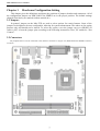
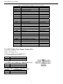
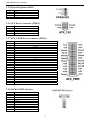
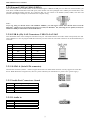
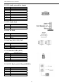
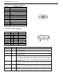
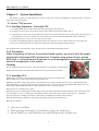
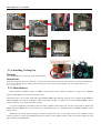
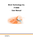
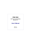
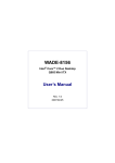
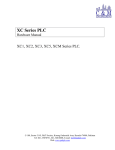
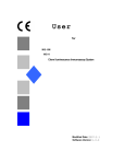
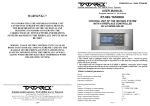
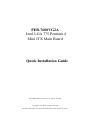
PEB-7600VG2A Intel LGA 775 Pentium 4 Mini ITX Main Board Quick Installation Guide P/N: PEB-7600VG2A Version 1.0 , August, 02 .2006 Copyright© Jun., 2002. All rights reserved All other brand names are registered trademarks of their respective owners. PEB-7600VG2A User’s Manual Note : (1)Memory type support dual-channel interleaved mode assuming DDR 400 MHz, all DIMMs in a system must be of the same type, the speed in all channels is the speed of the slowest DIMM in the system. (2)The Power Supply must be support Ver 2.2 or Ver 2.3 or high version. 1 PEB-7600VG2A User’s Manual Chapter 1 Hardware Configuration Setting This chapter gives the definitions and shows the positions of jumpers, headers and connectors. All of the configuration jumpers on PEB-7600VG2A SERIES are in the proper position. The default settings shipped from factory are marked with an asterisk (). 2.1 Jumpers In general, jumpers on the Mini ITX are used to select options for certain features. Some of the jumpers are designed to be user-configurable, allowing for system enhancement. The others are for testing purpose only and should not be altered. To select any option, cover the jumper cap over (SHORT) or remove (NC) it from the jumper pins according to the following instructions. Here, NC stands for “Not Connect”. 2.2 Connectors I/O peripheral devices will be connected to the interface connectors in (Figure 2-2) PEB-7600VG2A SERIES Connector Locations. 2 PEB-7600VG2A User’s Manual Figure 2-2 PEB-7600VG2A SERIES Connector Locations CONNECTOR PANEL1 1-3 PANEL1 2-4 PANEL1 6-8 PANEL1 5-7 VGA DVI SPK1 IDE1 PWR1 PWR2 COM1 COM2 PRT1 USB1 USB2 USB3 USB4 USB5 USB6 USB7 USB8 SPDIF I/O AUDIO1 CD1 IR1 GPIO1 KBMS1 SATA1 SATA2 SATA3 SATA4 TJ1 FUNCTION IDE1 active indicator System Power On LED System Power on Switch System reset DUB-15 port DF13-20DP External speaker interface IDE1 (Primary) interface 24-PIN ATX Power connector PW-4P2R Power connector COM1 serial port COM2 serial port Parallel port connector USB 2.0 port 1 USB 2.0 port 2 USB 2.0 port 3 USB 2.0 port 4 USB 2.0 port 5 USB 2.0 port 6 USB 2.0 port 7 USB 2.0 port 8 SPDIF I/O interface AUDIO interface CD-in from CD-ROM IR interface GIOS interface PS/2 keyboard & mouse connector Serial ATA interface Serial ATA interface Serial ATA interface Serial ATA interface For procreation test 2.2.1 RTC CMOS Clear Jumper Setting (JP1) OPEN: Normal operation SHORT: Clear CMOS contents 2.2.2 System Reset (PANEL1 5-7) PIN No. Signal Description 7 Reset 9 Ground 2.2.3 IDE1 active indicator (Panel1 pin #1-3) PIN No. Signal Description 1 +5V (Pull-up for HDD LED) 3 HDD active# (LED cathode terminal) 2.2.4 ATX Power Button (PANEL1 6-8) PIN No. Signal Description 6 Power button control signal 8 Ground 3 REMARK VGA connector Hirose:DF13-20DP For CPU Power COM1 connector 2x5 shrouded header Printer connector USB1LAN1 connector USB1LAN1 connector USB2LAN2 connector USB2LAN2 connector USB3 connector USB3 connector USB4 connector USB4 connector 1x4 shrouded header 2x5 shrouded header 1x4 shrouded header 2x3 shrouded header 2x5 shrouded header Double deck connector SATA connector SATA connector SATA connector SATA connector 2x4 shrouded header PEB-7600VG2A User’s Manual 2.2.5 External Speaker (SPK1) PIN No. 1 2 3 4 Signal Description Signal NC Ground +5V 2.2.6 ATX Power Connector (PWR2) PIN No. 1 2 3 4 Signal Description 12V_Power Ground 12V_Power Ground 2.2.7 ATX_24P2R Power Connector (PWR1) PIN No. 1 2 3 4 5 6 7 8 9 10 11 12 13 14 15 16 17 18 19 20 21 22 23 24 Signal Description +3.3V +3.3V Ground +5V Ground +5V Ground PW_OK +5V SB +12V +12V +3.3V +3.3V -12V Ground PS ON Ground Ground Ground -5V +5V +5V +5V Ground 2.2.8 COM1/COM2 Interface PIN No. 1 2 3 4 5 6 7 8 9 10 Signal Description Data Carrier Detect Received Data Transmit Data Data Terminal Ready Ground Data Set Ready Request To Send Clear To Send Ring Indicator Not used 4 PEB-7600VG2A User’s Manual 2.2.9 External USB3 & USB4 (USB2.0) This mainboard provides 2 USB headers on the board allowing for 4 additional USB ports. To make use of these headers, you must attach a USB bracket/cable with USB ports (some models will come packaged with a USB 4-port bracket-cable). The optionally packaged bracket will have two connectors that you can connect to the headers (USB1, USB2). The other end (bracket containing the USB ports) is attached to the computer casing. Note : If you are using a USB 2.0 device with Windows 2000/XP, you will need to install the USB 2.0 driver from the Microsoft® website. If you are using Service pack 1 (or later) for Windows® XP, and using Service pack4 (or later) for Windows® 2000,you will not have to install the driver. 2.2.10 USB & (Gb) LAN Connectors: USB/ Gb LAN 1&2 This mainboard comes with 4 USB ports and a Gb/s LAN port. The USB connectors are used to attach to keyboards, mice and other USB devices. You can plug the USB devices directly into this connector. The LAN connectors can be attached directly to a network. Pin Signal Description Pin Signal Description 1 TX+ 5 NC 2 TX- 6 RX- 3 RX+ 7 NC 4 Pin NC Signal Description 8 Pin NC Signal Description 1/5 +5 V (fused) 3/7 USBP0+/P1+ 2/6 USBP0-/P1- 4/8 Ground 2.2.11 SATA1-4 (Serial ATA connector) These SATA connectors (SATA1 – SATA4) support Serial ATA 150. Each SATA connector can only support one serial ATA device. Note: With most storage devices, there is a power cable that you need attach to a power source (power supply). 2.2.12 Audio Port Connectors: Sound PIN No. 1 2 3 4 Signal Description SPO VCC5 NC GND 2.2.12.1 Audio in PIN No. 1 2 3 4 Signal Description CD-L CD-GND CD-GND CD-R 5 PEB-7600VG2A User’s Manual 2.2.12.2 Audio external for chassis PIN No. 1 2 3 4 5 6 7 8 9 10 Signal Description F_MIC1 GND F_MIC2 VCC5 LOUTR F_R NC NC LOUTL F_L 2.2.12.3 Audio Jack PIN No. Signal Description 1(Blue) Lin-in 2(Green) Speak-Out 3(Red) MIC-in 2.2.13 CPU FAN PIN No. 1 2 3 4 Signal Description Ground +12V RPM signal Control 2.2.14 Chas_FAN / SYS_FAN PIN No. Signal Description 1 Ground 2 3 +12V RPM signal 2.2.15 Standard IrDA (KEY) PIN No. 1 2 3 4 5 6 Signal Description NC Not Used +5V Ground IRTX IRRX 2.2.16 PS/2 Keyboard & Mouse(KBMS1) PIN No. 1 2 3 4 5 6 Signal Description Keyboard Data Mouse Data Ground +5V Keyboard Clock Mouse Clock 6 PEB-7600VG2A User’s Manual 2.2.17 VGA D-SUB15 Connector PIN No. 1 2 3 4 5 6 7 8 9 10 11 12 13 14 15 Signal Description Red Signal Green Signal Blue Signal NC GND GND GND GND VCC GND NC DCC_DATA HSYNC VSYNC DCC_CLK 2.2.18 VGA DVI Connector Signal TDC0# TDC0 NC NC TDC1# TDC1 NC NC TDC2# TDC2 PIN 2 4 6 8 10 12 14 16 18 20 Signal TDC0,TDC0# Type O TDC1,TDC1# O TDC2,TDC2# O HPDET I TMDSDATA I/O TMDSDCLK I/O TLC,TLC# O 1 3 5 7 9 11 13 15 17 19 Signal VCC5 GND NC NC HPDET MDVIDATA MDVICLK GND TLC# TLC Signal Description DVI Data Channel 0 Output: These pins provide the DVI differential output for data channel 0 (Blue). DVI Data Channel 1 Output: These pins provide the DVI differential output for data channel 1 (Green). DVI Data Channel 2 Output: These pins provide the DVI differential output for data channel 2 (Red). Hot Plug Detect (internal pull-down): This input determines whether the DVI is connected to a DVI monitor. When terminated , the monitor is required to apply a voltage greater than 2.4 volts. Changes on the status of this pin will be relayed to the graphics controller via the P-OUT/TLDET* or GPIO(1)/TLDET* pin pulling low. DVI I2C Data: This signal is used as the I2C DOC clock for a digital display connector (i.e. TV-Out Encoder , TMDS transmitter ). This signal is tri-stated during a hard reset. DVI DOC Clock: This signal is used as the DOC clock for a digital display connector (i.e. primary digital monitor). This signal is tri-stated during a hard reset. DVI Clock Output: These pins provide the differential clock outputs to the DVI interface corresponding a data on TDC(0:2) outputs. 7 PEB-7600VG2A User’s Manual Chapter 2 System Installation This chapter provides you with instructions on how to setup your system. The additional information shows you how to install CPU/ FAN and memory . 2.1 Socket 775 Processor 2.1.1 Installing Pentium 4 / Celeron D CPU (1). Lift the handling lever of CPU socket outwards and upwards to the other end. (2). Align the processor pins with pin hones on the socket. Make sure that the notched corner or (3). dot mark (pin 1) of the CPU corresponds to the socket’s bevel end. Then press the CPU gently until it fits into place. If this operation is not easy or smooth, don’t do it forcibly. You need to check and rebuild the CPU pin uniformly. (4). Push down the lever to lock processor chip into the socket. (5). Follow the installation guide of cooling fan or heat sink to mount it on CPU surface and lock it on the socket 775. (6). Be sure to follow particular CPU speed and voltage type to adjust the jumper settings properly. Having figured out in general what you get, the next job is to bite the bullet and build your PC 2.1.2 Precautions When integrating a Pentium 4 processor-based system, be sure to take the proper electrostatic discharge (ESD) precautions. Consider using ground straps, gloves, ESD mats, or other protective measures to avoid damaging the processor and other electrical components in the system. Warning Do not touch socket sensitive contacts. Chain tech assumes no responsibility for the potential damages caused by this action and therefore the warranty we provide may be invalid. 2.1.3 Installing CPU #1 Disengage Load Lever by depressing down and out on the hook to clear retention tab. Rotate Load Lever to fully open position at approximately 135° #2 Rotate Load Plate to fully open position at approximately 100°. Remove Socket Protective Cover. With left hand index finger and thumb to support the load plate edge, engage protective cover finger tab with right hand thumb and peel the cover from LGA775 Socket while pressing on center of protective cover to assist in removal. #3 Locate the two orientation key notches. #4 Grasp the processor with thumb and index finger. (Grasp the edges without the orientation notches.) The socket has cutouts for your fingers to fit into. Carefully place the package into the socket body using a purely vertical motion. (Tilting the processor into place or shifting it into place on the socket can damage the sensitive socket contacts.) #5 Verify that package is within the socket body and properly mated to the orientation keys #6 Close the socket by 1. Close the Load Plate 2. While pressing down lightly on Load Plate, engage the Load Lever. 3. Secure Load Lever with Load Plate tab under retention tab of Load Lever 8 PEB-7600VG2A User’s Manual 2.1.4 Installing Cooling Fan Warning For a safety landing, avoid leaving prongs on hard surface. Instructions Smear thermal grease on the top of the CPU. Lower the CPU fan onto the CPU/CPU socket and secure it using the attachments or screws provided on the fan. Finally, attach the fan power cable to the CPUFAN adapter. For more details on this, go to http://www.intel.com 2.1.5 Main Memory PEB-7600VG2A SERIES provides 2 DIMMs (184-pin Dual In-line Memory Module) to support 2.6V DDRAM (Synchronized DRAM) as on-board main memory. The maximum memory size is 256B~ 1GB with using 256MB/512MB/1GB technology. Supports up to 2 double sided DIMMs at 266/333/400MHz. The memory architecture adopts 128-bit data interface to support for x8 and x16 DDRAM(DDR1) device width. In addition, it only support Non-ECC memory . For system compatibility and stability, don’t use memory module without brand. You can also use the single or double-side DIMM .The three DIMMs can be out of order. You can install different size of DDRAM module on DIMM1, DIMM2 or all to boot up system. Without out the contact and lock integrity of memory module with socket, it will impact on the system reliability. Follow normal procedure to install your DDRAM module into memory socket. Before locking, make sure that the module has been fully inserted into the DIMM slot. 9 PEB-7600VG2A User’s Manual NOTE: For maintaining system stability, do not change any of DDR memory parameters in BIOS setup to upgrade your system performance without acquiring technical information. 10