1
SilverLode™ CANopen®
User Manual
Revision 1.5
22 July 2009
For QuickControl Rev 4.6
CANopen User Manual Rev 1.5
Page 1 of 121
Table of Contents
Trademarks ..................................................................................................................... 6
Copyright......................................................................................................................... 6
Chapter 1 - Getting Started ............................................................................................. 7
Hardware Setup........................................................................................................... 7
QuickControl and CANopen ...................................................................................... 10
Combo-Commands ................................................................................................ 10
Slave, Master, Peer (Network Structure)................................................................ 10
CAN Initialization.................................................................................................... 11
Details: CAN Identity (CID) ................................................................................ 11
Details: CAN Baud Rate (CBD) ......................................................................... 11
Register Sharing Peer-To-Peer ................................................................................. 12
Transmitting ........................................................................................................... 12
Receiving (Mapping) .............................................................................................. 13
Advanced TPDO and RPDO .................................................................................. 14
Edit Register Mapping Option............................................................................. 14
TPDO Communication Parameters .................................................................... 14
Register Sharing Master-Slave .................................................................................. 15
Programming Unit 16 from Unit 1........................................................................... 15
Programming Unit 17 from Unit 1........................................................................... 16
Output Sharing .......................................................................................................... 18
Input Sharing ............................................................................................................. 19
Using Remote Inputs.............................................................................................. 21
In Move Commands ........................................................................................... 21
Flow Commands................................................................................................. 21
Chapter 2 – Introduction to CAN ................................................................................... 22
CAN Capabilities........................................................................................................ 22
CAN ........................................................................................................................... 22
CAN Physical Layer ............................................................................................... 22
CAN Bus Termination ............................................................................................ 23
CANopen Bus Length versus Baud Rate ............................................................... 24
CAN Message Frame Structure................................................................................. 25
CAN and Message Identifiers ................................................................................ 25
CAN Frame Structure............................................................................................. 25
Priority Arbitration................................................................................................... 25
CAN Bus Frame Fields .......................................................................................... 27
Chapter 3 – CANopen Protocol..................................................................................... 29
Introduction to CANopen Communications................................................................ 29
Network Management (NMT) Objects ....................................................................... 29
Monitoring NMT State Status..................................................................................... 30
Service Data Objects (SDO)...................................................................................... 31
Process Data Objects (PDO)..................................................................................... 32
Predefined Objects .................................................................................................... 33
SYNC ..................................................................................................................... 33
EMCY..................................................................................................................... 33
TIME ...................................................................................................................... 34
CANopen User Manual Rev 1.5
Page 2 of 121
Chapter 4 - QuickControl And CANopen....................................................................... 35
Input Sharing Details ................................................................................................. 35
Remote Output Control.............................................................................................. 35
Advanced CANopen Configuration ............................................................................ 36
Heartbeat................................................................................................................... 37
Limit and Home Switch Mapping ............................................................................... 37
Profile 402 Objects .................................................................................................... 38
CAN STATUS LED and CAN ERR LED .................................................................... 38
Chapter 5 - CANopen Commands................................................................................. 39
CAN Baud Rate (CBD) .............................................................................................. 39
CAN Connect to Remote (CCTR) .............................................................................. 40
CAN Dictionary Access, Local (CDL)......................................................................... 41
CAN Dictionary Access, Remote (CDR) .................................................................... 43
CAN Identity (CID) ..................................................................................................... 46
CAN Set NMT State, Local (CNL).............................................................................. 47
CAN Set NMT State, Remote (CNR) ......................................................................... 48
CAN Register Map, Local (CRML)............................................................................. 50
CAN Register Map, Remote (CRMR) ........................................................................ 52
CAN Transmit Register, Local (CTRL)....................................................................... 54
CAN Transmit Register, Remote (CTRR) .................................................................. 56
Chapter 6 - CANopen Configuration.............................................................................. 58
Starting Up CAN ........................................................................................................ 58
Configuring Process Data Objects (PDO).................................................................. 58
Initial PDO Configuration at Startup ....................................................................... 60
Transmit PDO Configuration .................................................................................. 60
CANopen Message Structure: COB-ID Allocation ..................................................... 63
EMCY Configuration .................................................................................................. 64
Heartbeat Configuration............................................................................................. 64
Chapter 7 - CANopen Data Dictionary .......................................................................... 66
Object Dictionary Structure........................................................................................ 66
Supported Simple Data Types ................................................................................... 66
Supported Manufacturer Data types: ......................................................................... 67
Object Dictionary Object Type Codes........................................................................ 67
Supported Structures / Complex data types .............................................................. 68
Supported Objects ..................................................................................................... 70
1000h Device Type ............................................................................................... 70
1001h Error Register............................................................................................. 70
1002h Manufacturer Status Word .......................................................................... 71
1003h – Predefined Error Field .............................................................................. 72
1005h COB-ID SYNC............................................................................................. 73
1006h Communication Cycle (SYNC) Period......................................................... 74
1007 h Synchronous Window Length..................................................................... 74
100Ch Guard Time................................................................................................. 74
100Dh Life Guarding .............................................................................................. 74
1012h TIME STAMP COB-ID................................................................................. 75
1013h High Resolution Time Stamp....................................................................... 75
1014h COB-ID EMCY ............................................................................................ 76
1015h EMCY Inhibit Time ...................................................................................... 76
1016h Consumer Heartbeat Time .......................................................................... 76
1017h Heartbeat Producer Time ............................................................................ 77
CANopen User Manual Rev 1.5
Page 3 of 121
1018h Identity Object ............................................................................................. 78
1019h Synchronous Counter ................................................................................. 78
1029h Error Behavior Object.................................................................................. 79
1200h SDO Server 1 Parameters .......................................................................... 79
1201h SDO SERVER 2 Parameters ...................................................................... 80
1280h SDO CLIENT 1 Parameters ........................................................................ 80
1281h SDO Client 2 Parameters............................................................................ 81
1400h 1st Receive PDO Communications Record ................................................. 81
1401h 2nd Receive PDO Communications Record ............................................... 81
1402h 3rd Receive PDO Communications Record ................................................ 82
1403h 4th Receive PDO Communications Record ................................................ 82
1600h First Receive PDO Mapping........................................................................ 83
1601h Second Receive PDO Mapping................................................................... 84
1602h Third Receive PDO Mapping....................................................................... 84
1603h Fourth Receive PDO Mapping .................................................................... 84
1800h – 1803h Transmit PDO Communications Parameters ................................ 85
1800h First Transmit PDO Communications Parameters ...................................... 86
1801h Second Transmit PDO Communications Parameters ................................. 86
1802h Third Transmit PDO Communications Parameters ..................................... 86
1803h Fourth Transmit PDO Communications Parameters ................................... 87
1A00h First Transmit PDO Mapping ...................................................................... 87
1A01h Second Transmit PDO Mapping ................................................................. 87
1A02h Third Transmit PDO Mapping ..................................................................... 88
1A03h Fourth Transmit PDO Mapping ................................................................... 88
Manufacturer Specific Data Dictionary Objects 2000H – 2FFFh ............................... 88
2000h Critical Error Mask....................................................................................... 89
2001 EMCY Report Mask ...................................................................................... 91
2002 CAN Errors Reported Register...................................................................... 93
2003h Trigger Event Driven PDO........................................................................... 94
2004h Limit Switch and Home Switch Mapping ..................................................... 94
2005h Heartbeat Monitoring Status/State .............................................................. 97
2006h Read/Clear CAN Hardware Error Status Bits .............................................. 98
2007h Current CAN ERRORS Register ................................................................. 98
2008h Remote Input Register Map ........................................................................ 98
2009h SSI Data Port .............................................................................................. 99
200Ah CAN Switch Data ........................................................................................ 99
User Register Mapping to CAN Data Dictionary ...................................................... 100
Objects 2100h to 21FCh ...................................................................................... 101
402V02 Object Mapping .......................................................................................... 107
6007h Abort Connection Option Code ................................................................. 108
603Fh – Most Recent Error Code ........................................................................ 108
6040h Control Word ............................................................................................. 108
6041h Status Word .............................................................................................. 109
605Ah Quick Stop Options................................................................................... 109
605Bh Shutdown Option ...................................................................................... 110
605Ch Disable Option .......................................................................................... 110
605Dh Halt Option................................................................................................ 111
605Eh Fault Reaction Option ............................................................................... 111
6060h Modes of Operation................................................................................... 112
6061h Modes of Operation Display ...................................................................... 112
CANopen User Manual Rev 1.5
Page 4 of 121
6062h Position Demand Value............................................................................. 112
6063h Position Actual Value ................................................................................ 113
6064h Position Actual Value ................................................................................ 113
607Ah New Target Position ................................................................................. 113
607Ch Home Offset ............................................................................................. 113
607Dh Position Limits Array ................................................................................. 114
607Fh Maximum Profile Velocity.......................................................................... 115
6081h Profile Velocity .......................................................................................... 115
6083h Profile Acceleration ................................................................................... 115
6084h Profile Deceleration................................................................................... 115
6085h Quick Stop Deceleration ........................................................................... 116
6098h Homing Method......................................................................................... 116
6099h Homing Speeds Array ............................................................................... 116
609Ah Homing Acceleration................................................................................. 117
60C5h Maximum Acceleration ............................................................................. 117
60C6h Maximum Deceleration ............................................................................. 117
60F2h Position Demand Value............................................................................. 117
60F4h Following Error Actual Value..................................................................... 118
60FCh Position Demand Value ............................................................................ 118
60FDh Digital Inputs............................................................................................. 118
60FEh Digital Outputs .......................................................................................... 119
6502h Supported Drive Modes ............................................................................ 120
67FFh Single Device Type ................................................................................... 120
CANopen User Manual Rev 1.5
Page 5 of 121
Trademarks
QuickControl® and QCI® are Registered Trademarks of QuickSilver Controls, Inc.
SilverLode™, SilverNugget™, SilverDust™, PVIA™, QuickSilver Controls™, and
AntiHunt™ are trademarks of QuickSilver Controls, Inc.
CANopen® and CiA® are registered community trade marks of CAN in Automation e.V.
Copyright
The SilverLode servo family's embedded software, electronic circuit board designs,
embedded CPLD logic, and this User Manual are Copyright 1996-2006 by
QuickSilver Controls, Inc.
CANopen User Manual Rev 1.5
Page 6 of 121
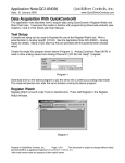
Chapter 1 - Getting Started
Chapter 1 - Getting Started
This chapter will get take you through the basics of using CAN on the SilverDust
controller/driver including register and I/O sharing.
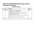
Hardware Setup
There are four physical connections for the CAN bus:
CAN V+ (Power in DC 7V-24V)
CAN V- (Power Ground 0V)
CAN H (CAN High)
CAN L (CAN Low)
2
V-
V+
V+ Pr
DRV ENA
Clamp +
Clamp -
CHSSY
CAN V+
IO +24
IO +24
IO +24
IO +24
IO +24
IO +24
IO +24
IO GND
IO GND
IO GND
IO GND
IO GND
IO GND
IO GND
IO GND
1
9
2
10
1
11
12
13
A/R
6
14
7
15
8
16
B
Z
B/5
Z/6
232 / 485
232 / 485
4
5
A
A/4
ENC IN
3
B/T
IO GND
IO GND
IO GND
IO GND
1
9
2
10
3
11
RT
4
12
B/T
5
13
A/R
6
14
7
15
8
16
GND
ENC ERROR
ENC ERROR
COMM
COMM
STATUS
MOTOR / ENC
CAN V-
Term
CAN H
IO +24
IO +24
ENC OUT
IO +24
IO +24
RT
GND
CAN L
V-
V+
V+ Pr
DRV ENA
ENC IN
Z/6
Clamp +
A/4
B/5
Clamp -
Z
CHSSY
B
CAN V+
CAN V-
Term
CAN H
CAN L
ENC OUT
See Note
A
IO +24
STATUS
COMM / IO
MOTOR / ENC
COMM / IO
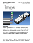
1) If all QCI-D2-IGB units are within a few feet of each other (or on the same DIN rail),
connect the two DB-9 together to form the CAN bus. Please note that power (24V max)
must be provided to at least one unit through the green terminal block. In addition,
termination should only apply at the end of the bus. In this case, there are only two
units on the bus, so the terminations are on both of the units.
2) The second option is wiring all the connections through the green terminals. There
are four physical connections on the QCI-D2-IGB. QuickSilver recommends using CAT
5 twisted pair cables commonly referred to as Ethernet cable. CAT 5 cables are
inexpensive, rugged, reliable, and are available in almost every local electronic store.
They also are twisted pairs with controlled impedances and relatively low capacitances.
3) A 5th pin is provided to connect a CAN termination. This is jumpered to CAL_L only at
the far ends of the run.
CANopen User Manual Rev 1.5
Page 7 of 121
Chapter 1 - Getting Started
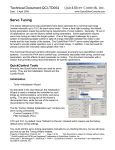
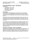
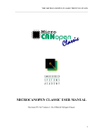
4) QCI-D2-IG8 controllers have three physical connections for CAN. Wires may be
landed on the 5 pin screw terminal connectors on the front panel.
These pins are
labeled as:
SHLD (Shield)
V+
(12-24v)
L
(CAN_L)
H
(CAN_H)
V(0v)
Only L, H, and V- are
needed for the IG8 as
an isolated
CAN power is derived
from the
processor/driver
power input. The
Shield and V+ signals
are provided to power
the RJ12 connectors,
but are not otherwise
used in the IG8.
All 5 signals are also connected to the RJ12 connectors on the bottom of the unit.
These connectors provide for easy daisy-chaining of the QCI-D2-IG8 units via untwisted
RJ12 patch cords. These are available from QCI. This unit also has CAN status LEDs
and CAN address and Baud Rate switches. See QCI-DS-018 for details.
(BP2) CAN Daisy Chain Interface
Pinout
1 CAN SHIELD
2 CAN V+
3 CAN H
4 CAN L
5 CAN GND
6 CAN SHIELD
1
6
1
6
5) The CAN signals for the QCI-D2-IGB and the QCI-D2-IG8 are galvanicly isolated
from the other controller signals. The CAN signals for the QCI-D2-MG-C are NOT
isolated, rather the CAN transceiver is powered from the local 5V supply. The CAN
transceivers used are internally protected to +/- 80v. This configuration allows
deployment of CAN within smaller systems at minimal cost.
CANopen User Manual Rev 1.5
Page 8 of 121
Chapter 1 - Getting Started
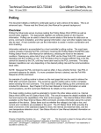
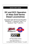
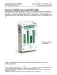
6) The QCI-D2-MG provides only three, non-isolated, CAN connections: CAN_L,
CAN_H, and GND. These signals may be connected to isolated CAN signals, or to
other non-isolated CAN signals if the Ground signals are common with in the system.
CAN_L
CAN_H
GND
The power for the
CAN is derived
from the local +5V
supply, thus no
extra power source
for CAN is required.
CANopen User Manual Rev 1.5
Page 9 of 121
No provision for
onboard CAN
termination is
provided. The user
must provide a 120
ohm, ¼ to ½ watt
termination resistor
at each end of the
CAN run.
Chapter 1 - Getting Started
QuickControl and CANopen®
QuickControl 4.4 or greater required. QuickControl 4.4 can be found on QuickSilver
Controls website, www.QuickSilverControls.com under the Software section.
Combo-Commands
Combo-Commands were introduced in QuickControl Rev 4.4. Combo-Commands
provide a macro like program construct in which user selections cause the parameters
of multiple native commands to be simultaneously edited. All native commands have
three letter acronyms, where as the Combo-Commands have four letter acronyms, to
allow for easy recognition. The combo commands may be expanded to see the
underlying commands by right clicking on the Combo-Command and selecting Expand
from the pop up menu. They may be restored to a single line by the same process. The
individual commands are “greyed out” as they may not be edited individually. However,
they may be copied and pasted in to a program by selecting only the individual
commands (and not the Combo-Command) and performing a copy and then a paste
operation. At this point, they are no longer associated with the Combo-Command and
may be individually edited.
Slave, Master, Peer (Network Structure)
The QuickSilver CANopen implementation supports both Master-Slave configuration, in
which a “Master” device configures the other “Slave” devices via the CAN bus, as well
as Peer-To-Peer operation in which each node configures itself. These modes may also
be mixed, with some nodes “self configuring” while other nodes are remotely configured,
as could be the case with the use of CANopen encoders or I/O blocks.
CANopen User Manual Rev 1.5
Page 10 of 121
Chapter 1 - Getting Started
CAN Initialization
Each unit should be configured using the Initialization Wizard and the “Factory Default
Initialization – CAN.qcp” initialization file. This file has two extra commands, CAN
Identity (CID) and CAN Baud Rate (CBD). By default, it configures each node to
communicate at 1Mbit/sec using the same CAN ID as Unit ID (see below).
Factory Default Initialization – CAN.qcp
Details: CAN Identity (CID)
Every unit on the network must have a unique CAN
ID. A CAN ID of zero forces the CAN ID to be the
same as the serial communication Unit ID as set by
the Identity (IDT) command. For example, if the
IDT command sets Unit ID to 16, setting the CAN
ID to 0, will force the CAN ID to match the Unit ID
of 16.
Note: Unit ID in the IDT command is addressable from 1-255. If Unit ID is set to 128+,
and CAN ID=0, the CID command will error out.
Details: CAN Baud Rate (CBD)
CAN networks can operate up to 1 megabit per
second (1 Mb/sec). The trade off for lower baud
rate is bus length. QuickSilver’s default baud rate is
1Mb/sec
CANopen User Manual Rev 1.5
Page 11 of 121
Chapter 1 - Getting Started
Register Sharing Peer-To-Peer
User registers may be easily shared across the CAN network in a multi-axis application.
There are two ways to setup register sharing, one is Peer-To-Peer and the other is
Master-Slave (discussed in the next section).
Peer-To-Peer Network Diagram
<16 Data>...............<16 Data>................<16 Data>................<16 Data>
1
16
17
Transmitting
In Peer-To-Peer, each unit will “locally” configure itself to either transmit or receive. In
this example, unit 16 is configured to transmit its register onto the bus. Once
configured, any unit on the bus may receive the data. This is done using the CAN
Transmit Register, Local (CTRL) Combo-Command.
Each device has four independent
communication channels to transmit data.
Once configured, the data register will
transmit data “continuously” onto the bus.
In CANopen terminology, this is called a
Transmit Process Data Object (TPDO).
See TPDO section for more details.
CANopen User Manual Rev 1.5
Page 12 of 121
Chapter 1 - Getting Started
Once data transmission is configured, use the
CAN Set NMT State, Local (CNL) command to set
the Network Management (NMT) state to
Operational. This allows the unit to start
transmitting data.
Example Program: Unit 16 transmits its actual position onto the bus. See Diagram
above.
Receiving (Mapping)
One or more units on the CAN bus may receive
or map the transmitted register into any local user
Register using the CAN Register Map, Local
(CRML) Combo-Command.
The local receive channels are independent of
the local transmitting channels. In this example,
unit 17 will continuously receive data from the
unit 16. In CANopen terminology, this is called a
Receive Process Data Object (RPDO). See
RPDO section.
Example Program:
Note: If unit ID 1 wants to receive the same
data transmitted by unit 16, repeat this process.
At this point, the unit sourcing the data need
merely modify its local register to cause the
same data to appear in the remote node’s
mapped register. The register number of the
source (producer) is independent from the
receiving (consumer) node register. For
example, the actual position of the producer
node may be broadcast, with the consumer node mapping it to register 30.
CANopen User Manual Rev 1.5
Page 13 of 121
Chapter 1 - Getting Started
Advanced TPDO and RPDO
CAN Transmit Register, Local (Advanced)
The Advanced option has two parameters:
• Edit Register Mapping
• Edit TPDO communication Parameters.
Edit Register Mapping Option
This advanced function allows user to select a
second register for the same communication
channel. One TPDO channel can transmit up
to two registers at the same time.
By default, the second register transmission is
disabled. User must enable the second
channel and select the desired register.
TPDO Communication Parameters
This advanced function allows user to select the
type and frequency of transmission. See
Process Data Objects in Chapter 3 for details.
CANopen User Manual Rev 1.5
Page 14 of 121
Chapter 1 - Getting Started
Register Sharing Master-Slave
Master-Slave is the second option in setting up the CAN network. The advantage of
Master-Slave configuration is centralized control in large networks. Setting up each
peer to transmit and receive a PDO locally is not practical in a large network in terms of
software management because there are too many programs to keep track and debug.
In Master-Slave configuration, the master remotely configures the TPDO and RPDO on
the other nodes. There is only one program on the master unit, which makes
debugging easier.
<1 Config 16 to transmit>...<1 Config 17 to Receive>.....<16 Data>.............<16 Data>
1
CAN Init and Program
16
CAN Init
17
CAN Init
In this example, unit 1 will configure unit 16 to transmit it’s Actual position register onto
the bus using a TPDO. Then unit 1 will configure unit 17 to map unit 16's Actual
Position register into unit 17's local register using an RPDO.
Programming Unit 16 from Unit 1
Before any unit can be configured remotely,
a connection must be established. This is
done using the CAN Connect to Remote
(CCTR) Combo-Command.
Once the CCTR command is executed, Unit
1 can configure Unit 16 to transmit its
register using the CAN Transmit Register,
Remote (CTRR) Combo-Command. CTRR is just like the local version, CTRL except it
configures the "connected" remote unit to
transmit a register.
CANopen User Manual Rev 1.5
Page 15 of 121
Chapter 1 - Getting Started
Like the Peer-to-Peer example, the final step is to put the remote unit into NMT
Operational state. Master units put slaves into
Operational state using the CAN NMT State,
Remote (CNR) command.
Configuring any remote unit to transmit a
TPDO is a three step process. First, connect
to the remote unit. Second, configure the
TPDO. Third, put the remote unit into operational mode.
Programming Unit 17 from Unit 1
1) Use CCTR to connect to Unit 17.
2) Use CRMR to map 16's Transmit Channel #1
data to 17's register 30 through 17's Receive
Channel #1.
3) Set 17 to Operational using CNR.
Now, unit 16 will transmit its actual position register onto the bus. Unit 17 will receive
unit 16 TPDO into register 30 through its RPDO. The entire configuration was done
through unit ID 1. See diagram above.
CANopen User Manual Rev 1.5
Page 16 of 121
Chapter 1 - Getting Started
Example program
CANopen User Manual Rev 1.5
Page 17 of 121
Chapter 1 - Getting Started
Output Sharing
The following diagram and procedure shows how to have unit 16 share 17's outputs.
OUTPUT
16
17
Outputs
1) From unit 16, use CCTR to connect unit 17.
2) Use the CAN Dictionary Access, Remote
(CDR) command (Remote Output tab) to clear
or set a remote unit’s output.
For an example program see "QCI Examples\CAN\CDR Remote Output.qcp" in the
QuickControl folder.
CANopen User Manual Rev 1.5
Page 18 of 121
Chapter 1 - Getting Started
Input Sharing
Any device may share its extended inputs (i.e. #101-116) with everybody else on the
CAN network. A unit shares a remote unit's inputs by mapping a specific register on
the remote unit to a specific local register. Once mapped, the "Remote Inputs" can be
used in many commands just like local inputs (see below). For details on the specific
registers 238 and 199, see Input Sharing in Chapter 4.
The following diagram and procedure shows unit 16 sharing unit 17's inputs.
INPUTS
<17 TPDO Register 238>....<16 RPDO Register 199>
Map I/O Register 199
16
Map I/O commands
17
Unit 16 Sharing Unit 17's Inputs
CANopen User Manual Rev 1.5
Page 19 of 121
INPUTS
Chapter 1 - Getting Started
1) Unit 17 program uses CTRL to share the upper word of register 238 (extended I/O
input states) with everybody on the CAN bus.
2) Unit 16 program uses CRML to map unit 17's remote inputs to lower word of register
199.
CANopen User Manual Rev 1.5
Page 20 of 121
Chapter 1 - Getting Started
Using Remote Inputs
In Move Commands
All move commands can stop on remote unit’s input. Under the “Advance” option of any
move command, the user may select any remote input.
Flow Commands
The following Program Flow commands can use
remote inputs:
• Jump On Input (JOI)
• Program Call On Input (PCI)
• Program Return On Input (PRI)
• Wait On Bit Edge (WBE)
• Wait On Bit State (WBS )
This is the end of the Getting Started chapter. For users who want to fully understand
CAN structures and how it really works "under the hood", please continue….
CANopen User Manual Rev 1.5
Page 21 of 121
Chapter 2 – Introduction to CAN
Chapter 2 – Introduction to CAN
CAN Capabilities
CAN provides a robust networking capability, and has been in use for more than 15
years. Originally designed for the harsh under-hood car environment, it has multiple
error detection and correction methods built in to provide predictable, robust, and
virtually error-free communications for industrial control. The network allows multimaster, multi-destination communications, with communication speeds up to 1Mbit per
second. Each frame of data sent includes a message identifier; this is used by all of the
receiving nodes to determine if they are configured to react to the frame. This allows
data to be sent from one to many nodes, with all nodes receiving the message at the
same point in time.
CAN uses a message arbitration scheme rather than a message collision scheme to
decide which node on the network is allowed to transmit its data in a particular time slot.
The message assigned the highest priority goes first with no impact on its sending time,
even if other nodes are attempting to send lower priority messages. The lower priority
messages then follow, highest priority to lowest priority.
Using the CAN framework for communications, nodes may share registers, with any
change in the shared register automatically reflected in multiple other nodes. A master
node may control other nodes – even resetting them. Error conditions may be conveyed
between nodes on occurrence rather then requiring constant polling to determine error
conditions. Register read and write operations are allowed between nodes. Data may
be exchanged based on update times, synchronous events, upon changes in data, or
combinations of these, with provisions for minimum and maximum update rates, all
operating modally in the background without user program intervention. This allows cam
following operations to use a CANopen encoder, or another node’s target or position to
control another node, without extra step-and-direction wiring.
It is also easy to implement automatic Heartbeat monitoring, in which each node
produces a timed heartbeat signal, and up to eight other nodes are monitored for their
presence as well as critical changes in state. A consistent system time may be
distributed across multiple nodes, with each other node frequency locking their local
time to the designated master node to eliminate the effects of differences in oscillator
frequencies.
CAN
The CAN network and its principles of operation were originally defined by Bosch:
(www.can.bosch.com), standardized by the International Organization for
Standardization as ISO11898
CAN Physical Layer
CANopen defines a Physical layer having at least two nodes connected by a twisted
pair data bus, having each end of the data bus terminated with 120 ohms. (See data
sheets for connections, power requirements, etc.) The Bus assumes one of two states
at any point in time, Passive or Dominant. Passive state exists when no drivers are
CANopen User Manual Rev 1.5
Page 22 of 121
Chapter 2 – Introduction to CAN
active on the bus, causing the differential voltage to be pulled close to zero due to the
action of the terminating resistors. The Dominant state exists when one or more of the
bus drivers are driving the bus; in the Dominant state the CAN_H line is driven high
(approximately 4v typically) while the CAN_L line is driven low (approximately 1v). The
state of the bus thus assumes a level which is the logical “OR” (active low logic) of the
transmitters on each of the nodes of the bus – that is it is in the Passive state if all of the
nodes are transmitting a passive state (driver inactive) and it is in the dominant state if
any of the nodes are transmitting a dominant state (driver active). Each node monitors
the state of the bus, both when listening and when transmitting. The Dominant State
Represents a “0” level, while the Recessive State represents a “1” level.
CAN Bus Termination
120 ohm termination resistors are required at each end of the bus. These terminating
resistors are required even for very small networks, as the drivers only drive in the
Dominant state, while the line terminators return the network to the Passive state levels.
The wiring between nodes should be twisted pair 120 ohm impedance wire, preferably
shielded. The two CAN_H and CAN_L should be one pair of wires, while CAN_V+ and
CAN_V- should be on a separate set of wire. The CAN enabled SilverLode controllers
include a 120 ohm terminating resistor that may be connected by wiring between
CAN_L and TERM; only the units at the ends of the bus should be terminated.
On the CAN enabled SilverLode controllers, the CAN bus signals CAN_H and CAN_L
should be twisted pair wiring, preferably shielded. The signals may be connected via the
topside terminal strips or via the 9-pin D-Sub connectors. It is common practice to feed
the CAN power from approximately the center of the network, along with the CAN
signals. Use only one connection from the power source to the CAN power bus to
prevent ground loops which may degrade signals and increase EMI emissions and
susceptibility.
WARNING: The 9 pin CAN/COMM connectors carry both Communications and CAN
signals and do not follow the standard CANopen signal pin-out convention. See the
documentation before connecting anything to these connectors.
CANopen User Manual Rev 1.5
Page 23 of 121
Chapter 2 – Introduction to CAN
CANopen Bus Length versus Baud Rate
Maximum cable length is dependent upon the baud rate and upon the number of nodes
and wire gauge (See DR303 V 1.3). CANopen defines the following rates versus bus
lengths (we also support 100kbps):
Baud Rate
1 Mbps
800 kbps
500 kbps
250 kbps
125 kbps
50 kbps
20 kbps
10 kbps
Max Bus length
25 m
50 m
100 m
250 m
500 m
1000 m
2500 m
5000 m
The above Maximum bus length should include the length of all stubs on the bus, due to
their loading of the bus. These individual stub lengths should be kept to less than 2% of
the maximum bus length, with the sum of all of the stubs less than 10% of the maximum
Bus length.
Bus Length
Length related
resistance
Wire CrossSection
meters
Milliohm/meter Square mm
0 to 40
70
0.25 to 0.34
40 to 300
<60
0.34 to 0.6
300 to 600
<40
0.5 to 0.6
600 to 1000 <26
0.75 to 0.8
(Recommendations from DR 303-1 V1.3)
Wire Gauge
(approximat
e)
AWG
24 GA
22 GA
20 GA
18 GA
Terminatio
n
resistance
ohms
124
150 to 300
150 to 300
150 to 300
The baud rate for the Node is set via the CAN Baud Rate (CBD) command.
CANopen User Manual Rev 1.5
Page 24 of 121
Chapter 2 – Introduction to CAN
CAN Message Frame Structure
CAN and Message Identifiers
Each message sent across the bus is uniquely identified by a pre-assigned
Communications Object Identifier or COB-ID. The COB-ID not only designates the type
of communications and how its data will be handled, it also specifies the priority of the
message, with the lowest numbered COB-ID’s receiving the highest priority in
transmission.
Each Node must be assigned a unique CAN ID in the range of 1 to 127. The CAN ID is
used to build the default COB-ID values used by the frames, so a lower numbered node
will be assigned higher priorities by default. The CAN ID is set using the CAN Identity
(CID) command; this command assigns the ID, builds the default COB-ID values for the
various objects, and then starts up the CAN background processes.
CAN Frame Structure
The CAN Frame includes:
• Start of Frame (synchronizes multiple devices to arbitrate the bus)
• Arbitration Field (contains the Communication Object Identifier or COB-ID of the
Frame)
• Control Field (defines frame type and number of data bytes)
• Data Field (0 to 8 bytes of data)
• CRC Field (16 bit CRC to check for errors)
• ACK Field (Response that at least one other CAN device properly decoded the
frame)
• End of Frame (Quiet time at end of frame so new Start of Frame may be
detected)
A new CAN frame is permitted following a BUS IDLE period. The BUS IDLE period
consists of a sufficiently long period of Recessive state to indicate that no active frame
is present. Following a valid BUS IDLE, all nodes having messages to transmit assert a
Start of Frame. As the bus is wire-OR, all nodes will read the bus as Dominate State.
The falling edge of Start of Frame is used to synchronize all of the nodes for the
Arbitration Field (COB-ID).
Priority Arbitration
During the Arbitration Field, each node drives the bus the COB-ID of the message it is
sending, starting with the Most Significant Bit. Each node monitors the bus to determine
the resulting state of the CAN BUS. If the Node sees the same state on the BUS as it
was asserting, it is allowed to continue the arbitration the following bit cycle. If the node
sees a different state of the bus, it has lost the arbitration and must wait until the next
Interframe space to try again. Because the Dominant State represents a “0” level, and
because the Dominant State is present on the bus when both Dominant and Recessive
states are asserted by different nodes, the Node transmitting the message with the
lowest COB-ID (arbitration field) wins the arbitration cycle. This is repeated for all 11 (or
29) bits of the COB-ID. The node that was sending the lowest numbered COB-ID
remains active and continues to transmit the balance of the frame except for the ACK
bit. The ACK bit must be provided by a different Node to indicate that the frame was
CANopen User Manual Rev 1.5
Page 25 of 121
Chapter 2 – Introduction to CAN
received properly. If any error active Node detects a problem with the frame, it asserts
an Error Frame, which causes the sending Node to stop sending and to retry. (There
are several error recovery mechanisms built into CAN, not described here to simplify the
description.)
To restate, the highest priority messages need to be assigned the lowest COB-ID
values, while the lower priority messages are assigned the higher COB-ID values.
Upon receipt of a valid frame, each node (other than the node that originated the
Frame) then examines the COB-ID (transmitted during the Arbitration Frame) to see if it
needs to act upon the frame or whether it may discard the frame.
Note: It is important that all COB-ID values are unique to prevent more than one node
from winning arbitration, only to have mismatching data collide. This will result in
resending of data until nodes go offline due to excessive errors.
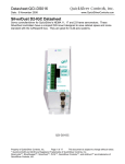
Non-Destructive Message Arbitration Process
COB-ID/
Arbitration field
Start Bit
11010001011
Node 1
COB-ID=68B
1 1 1 XXXXXXXX
Node 2
COB-ID=723
Node 2 loses arbitration
1 1 0 1 0 0 1 XXXX
Node 3
COB-ID=692
Node 3 loses arbitration
11010001011
Bus
CANopen User Manual Rev 1.5
Page 26 of 121
Chapter 2 – Introduction to CAN
CAN Bus Frame Fields
The basic message frame (including inter-frame intermission) consists of the following
bits, excluding data and bit stuffing:
Bits
3
1
11
1
2
4
0
16
2
7
Purpose
Intermission
Start of Frame (SOF)
Identifiers (COB-ID)
Remote Transmit Request
R0/R1 (reserved bits)
Data Length Count (DLC) = # of bytes
Data (0 to 8 bytes)
Cyclic Redundancy Code (CRC)
Acknowledge slot (ACK)
End of Frame (EOF)
47
Total
This represents the minimum frame size with no data payload. Eight bits of data are
added for each byte of data payload. However, the CAN specification prevents more
than 5 consecutive bits of the same value with in a packet (excluding the EOF and
intermission time); in the case of 5 consecutive bits of the same value, a “stuff bit” of the
opposite state is automatically inserted at the transmitter and removed by the receiver.
The Acknowledge slot must also have a fixed Passive Guard, Active Ack, Passive
Guard timing. This leaves 34 of the basic frame bits subject to bit stuffing rules, as well
as all of the data bytes. Bit stuffing is data/identifier dependent.
Minimum packet size it therefore 47+8*d where d=number of data bytes
Maximum packet size is 47+8*d + {34+8d-1}/4:
Bytes of Data
Minimum Packet - bits
Maximum Packet - bits
0
1
2
3
4
5
6
7
8
47 55 63 71 79 87 95 103 111
55 65 75 85 95 105 115 125 135
Min. Time @ 1Mbps - microseconds
Max. Time @ 1Mb/Sec - microseconds
Min. Time @ 250kbps - microseconds
Max. Time @ 250kbps - microseconds
47
55
188
220
55
65
220
260
63
75
252
300
71
85
284
340
79
95
316
380
87
105
348
420
95
115
380
460
103
125
412
500
111
135
444
540
Thus a frame carrying 0 bytes of data requires between 47us and 55us at 1Mbps baud
rate, while it takes 188us to 220us for the same packet if the bus speed is lowered to a
250kbps baud rate. A frame carrying 8 bytes of data takes between 111uS and 135us
vs. 444us and 540us for the same 1Mbps and 250 kbps data rates.
CANopen User Manual Rev 1.5
Page 27 of 121
Chapter 2 – Introduction to CAN
Example Data Frame with Two Bytes of Data
SOF
(Start of Frame)
COB-ID/
Arbitration field
Control Field
16 bit CRC
(example)
Data Field
ACK
Slot
End of Frame
110100010110000011000101001010100101010110010100001011111111
RTR (1=request, 0=message
IDE (0=11 bit, 1=29 bit)
R0 (Reserved Bit)
Stuff bit
CANopen User Manual Rev 1.5
00
10
Low Byte
29h
Data Length
Count (DLC)
Page 28 of 121
High Byte
52h
ACK is supplied by One
or more Other Nodes
ACK Delimiter - Must be Recessive,
or start of Error Frame
Chapter 3 – CANopen Protocol
Chapter 3 – CANopen Protocol
Introduction to CANopen Communications
CANopen provides communications between sensors, controllers, drives, I/O, and other
devices. This communication provides:
• Access to device and communication parameters
• Cyclical and event based process data communications
• Synchronization between devices
• Configuration
• Fault detection
Four Communication Objects (COB), each with its own characteristics are defined:
• Network Management (NMT, Heartbeat)
• Service Data Objects (SDO)
• Process Data Objects (PDO)
• Pre-defined objects (SYNC, EMCY, TIME)
CAN in Automation (CiA) is responsible for the standards and profiles that define the
CANopen standard (www.CAN-CiA.org).
All of the Node Data and Configuration available to and through the CAN bus is defined
in a data structured called the Data Dictionary. Each entry in the Data Dictionary is
called a Data Dictionary Object, and is referenced by an Index. These Objects may be
simple, such as bytes, words, long words, strings, etc., or may be complex, such as
arrays or data structures. A Sub-Index is used to reference the elements of complex
structures. Simple Objects use the appropriate Index with a Sub-Index = 0. Uploading
(reading) and Downloading (writing) of these Data Dictionary Objects will be described
in the SDO Object section, below. The object data may also be conveyed from it source
node to multiple destination nodes using various PDO Objects (see below).
Network Management (NMT) Objects
Each node on the network has a NMT state machine. The NMT state machine indicates
the Network state of the node.
• Resetting = Initializing and testing hardware
• Initializing Communications = Hardware OK, initializing CAN and default COBID’s
• Pre-Operatonal = able to process NMT and SDO objects, but not PDO objects
and Predefined Objects. Use this state to configure Nodes before they go active.
• Operational = able to process all object types (although some configuration
changes may not be allowed).
• Stopped = an error was detected, and the Node will only respond to NMT frames.
A Node is allowed to either change its NMT state itself (Master or Peer), or to wait until
a Master node changes its state.
The Master node may change the state of any other node by use of the Node Control
Protocol. The NMT operation may be used to cause the Node to transition to PreCANopen User Manual Rev 1.5
Page 29 of 121
Chapter 3 – CANopen Protocol
Operational, Operational or Stopped state; it may also reboot the node, or to cause the
node to reset its communication parameters their initialization state.
The local Node NMT state may be set via the CAN Set NMT State, Local (CNL)
command.
If the SilverLode is operating as the master, other nodes NMT state may be set via the
CAN Set NMT State, Remote (CNR) command.
See Starting up CAN for details.
Monitoring NMT State Status
Each node, upon completion of Initialization, transmits a Boot-Up Frame, and then
transitions to PreOperational state. This Boot-Up frame is of the same COB-ID and
form as the HeartBeat frame (described below), having a COB-ID of 1792 (700h) + CAN
ID, and having one byte of data to convey the NMT State. The “NMT State” field is zero
to indicate boot-up.
Each node may be configured to produce a “Heartbeat” message. The combination of
the COB-ID and the data indicates the current state of the given node. The presence of
the message being repeated/updated within the expected time frame indicates the node
is still alive and well. The NMT states expected in the heartbeat are:
0 = boot-up
4 = Stopped
5 = Operational
127 = Pre-Operational
The Heartbeat protocol allows each node to produce a “Heartbeat” frame at the
selected interval in milliseconds. The Heartbeat Producer time is configured by setting
the CAN Dictionary Object 1017:0 = to the desired time in milliseconds. A value of zero
disables the heartbeat.
Each node may also be configured to monitor one or more (SilverLode units allow up to
8) heartbeats associated with other nodes, via object 1018h. The user program may be
configured to react to the absence of a heartbeat as well as to the change in state of
another node to determine its own actions. The detecting nodes software (.qcp) must
be programmed to determine whether to shut down and/or disable itself and/or other
drives in the system, or to take other corrective or reporting action, if any. The Heartbeat
Consumer time should be configured to be somewhat longer than the monitored node’s
Heartbeat Producer Time to allow for bus loading delaying the heartbeat packet, as it is
a low priority message.
Note that the various NMT objects are “Unconfirmed” services, meaning the frame is
sent, but no response/confirmation is produced to the frame. Zero or more nodes may
be consumers of the given frame.
CANopen User Manual Rev 1.5
Page 30 of 121
Chapter 3 – CANopen Protocol
Service Data Objects (SDO)
Service Data Objects provide communications between nodes to allow the uploading
(reading) or downloading (writing) of Data Dictionary Objects of other nodes. These
services allow wide access to the various Data Dictionaries, but are slower, typically
using lower priority COB-Ids, and requiring a response, as the SDO services are all
Confirmed. The SDO services also require a one-to-one mapping from the SDO Client
(requestor of the read or write) to the SDO Server (node being read or written). Only
one Client should be mapped to each Server at a time, although each Node may
support multiple clients and servers. The SilverLode CANopen software provides two
clients and two servers per node.
The SDO service may be accessed through the CAN Dictionary Access, Remote (CDR)
command. Prior to using the CDR command, the SDO Communications Parameters
must be configured. Each Node has one Root SDO server that is configured to default
COB-Ids (Server Rx at 1536 (600h) + CAN ID, Tx at 1408 (580h) + CAN ID. The
communications parameters for this server are Read Only.
Accessing a remote SDO Server requires configuring the local Data Dictionary Objects
for the SDO Client being used (Client 1 or Client2). The Client Tx COB-ID must be set
to the wanted Server Rx COB-ID, and the Client Rx COB-ID must be set to the wanted
Server Tx COB-ID. Client SDO parameters are accessed via Data Dictionary Object
1280 Sub-Indexes 1 through 3).
The local Data Dictionary Objects may be accessed using the access CAN Dictionary
Access, Local (CDL) command. This command allows uploading (reading) from the
Data Dictionary object into User Registers, as well as downloading (writing) to the Data
Dictionary object from a constant or from User Registers.
CANopen User Manual Rev 1.5
Page 31 of 121
Chapter 3 – CANopen Protocol
Process Data Objects (PDO)
Process data objects provide real time data communications between nodes with
minimal program intervention. These objects are unconfirmed, meaning that the data is
sent to zero or more consumers, with each object having only one producer. Each PDO
object is provided with a unique COB-ID. PDO objects are normally configured to
operate in a Modal Fashion:– once they have been configured they continue to operate
autonomously in the background until they are again reconfigured.
The producer of a PDO must be configured to produce the PDO (send data). Likewise,
every consumer of a PDO must be configured to receive the PDO. Each PDO may only
have one producer, but may have zero or more consumers.
The producer configuration includes selecting:
• Which local Data Dictionary Objects to map into the PDO data
o Order of mapping and size of each object
o Number of objects mapped (up to 4) - Maximum of 8 bytes of data
• Synchronous or Asynchronous transmission
o Synchronous simultaneous updates all nodes at SYNC event
o May be sent every SYNC event, or every X SYNC events.
o May be sent on particular SYNC events, such as 1,4,7,…
o May be triggered by time or change, but sent at the next SYNC event.
• Triggering mechanism and/or Time interval
• Inhibit Time to prevent overloading the bus if rapid changes would otherwise
cause overly rapid triggering and transmission of data.
• COB-ID of the given PDO.
Each PDO consumer must also be configured, but require fewer parameters:
•
•
•
Which local Data Dictionary Objects receive the PDO data
o Order of mapping and size of each object
o Number of objects mapped - Maximum of 8 bytes of data
o The data does NOT need to be mapped to the same Data Dictionary
Object as was the PDO producer, and in practice is usually not mapped to
the same Object. The data sizes of the producer and consumer should be
compliant, however.
o The Consumer does NOT need to map all of the data sent by the
producer, but will produce an (optional) error is the more data is mapped
than sent by the producer.
Synchronous or Asynchronous operation - Synchronous updates the local object
at the next SYNC event, Asynchronous updates the object immediately.
COB-ID of the given PDO.
Once these objects have been configured, and the nodes are in the Operational NMT
state, the PDO producers automatically produce the PDO data frames, and the PDO
consumers automatically consume them. Common uses for PDO objects would be to
allow one node to send an operation state to one or more other nodes; to convey I/O
status from one node to one or more other nodes; to broadcast the position of a master
axis to one or more CAM following axes; or to use a CAN open encoder to provide
position feedback information to close a dual loop control operation.
CANopen User Manual Rev 1.5
Page 32 of 121
Chapter 3 – CANopen Protocol
Predefined Objects
CANopen also defines certain other objects to be used by the nodes. These include the
SYNC object, the EMCY object, and the TIME object.
SYNC
The SYNC object, with a default COB-ID of 128 (80H) is broadcast by the designated
node in the system, and consumed by the other nodes (that have configured to use the
same SYNC COB-ID). The SYNC event (completion of transmission of the SYNC object
for the SYNC producer, and the reception of the SYNC object for all SYNC producers)
causes all synchronous PDO producers to sample their data and begin sending data, as
well as all synchronous consumers to update their internal Data Dictionary Objects with
any data received since the last SYNC event.
The SYNC producer must be configured to select the SYNC period. It may optionally be
configured to send a SYNC cycle counter with the given cycle modulus. The SYNC
cycle counter may be used to cause PDO data production on the wanted SYNC cycle
from multiple nodes. For example, to prevent bus overloading, three different PDOs
could send on different SYNC cycles, with PDO “x” sending on cycles 1, 4, 7; PDO “y”
sending on cycles 2, 5, 8; and PDO “z” sending on cycles 3, 6, 9. Other PDOs could
produce data every SYNC event, while yet others send only when the Data changes.
EMCY
The EMCY object is used to signal emergency conditions from a Node to other nodes
monitoring the given node. These conditions include communications problems,
voltage, current and temperature problems, user or runtime code errors, etc.,. The
candidates for generating EMCY messages are enabled by setting the appropriate bits
via Object 2001H. (By default all are enabled unless Object 2001h is otherwise
configured.) Similarly, Object 2000h sets local CAN Error triggers (which cause the
CAN Error – Bit 10 in IS2 – to be set, able to trigger a Kill Motor Extended (KMX)
condition if KMX has been configured to include a trigger on the CAN Error bit.
The EMCY object includes the ID implicitly via the COB-ID, defaulting to 80h+NodeID,
unless modified via Object 1014h. Object 1015h sets the inhibit time for EMCY
messages so that they do not overload the communications.
Each time a qualified (see Object 2001h) error occurs, the contents of the Error register
data (Object 1001h) as well as a specific error code is transmitted. The error code
information is also saved to the Predefined Error Field, Object 1003h, with Sub-Index 0
indicating how many errors (0 to 4) are queued in the FIFO buffer of 1003h, with the
most recent error stored at Sub-Index 1, and the oldest at Sub-Index 4. (The FIFO
buffer implementation allows up to four errors before discarding the oldest). The error
storage may be cleared by writing a zero (0) to Sub-Index 0. When a qualified error that
has already been reported has cleared, then an Error Cleared frame is sent, indicating
any error conditions (Object 1001h) that may still be pending. Transient errors, such as
a short PDO frame will produce an Error frame followed by an Error Cleared frame, as
these errors are transient by nature. If the error repeats, it will only be reported after the
Error Cleared frame associated with that error has been sent, the multiple detections
CANopen User Manual Rev 1.5
Page 33 of 121
Chapter 3 – CANopen Protocol
being considered as a single error occurrence. Other errors, such as drive disabled or
over temperature, will only generate a single error message at the onset of the error,
and a single Error Cleared frame when the error has been resolved. Local action for any
of these errors may be triggered by configuring object 2000h as well as the appropriate
bits (including the CAN Error bit) in the Kill Motor Extended command.
The EMCY frame consists of eight bytes of data. The first two bytes are the EMCY
Error Code (EEC - see Object 2002h for a list of codes), sent low byte, high byte. Next
byte is a copy of the contents of the Error Register (Object 1001h), followed by an error
type byte, bit 0 indicates a hardware error, while bit 1 indicates a communications error.
The last four bytes are the current state of the Error Status bits (as of the time of the
EMCY frame), the same as the contents of Object 2007h.
TIME
The TIME object is used to broadcast Time of Day to all nodes in the system. The
nodes thus all keep time with the Time Master Node. The SilverLode CAN software also
provides crystal frequency compensation to allow the node to lock onto the master time
to cancel out crystal tolerance and drift between nodes. (The master may have drift with
respect to true time, but all nodes on the bus will drift together.) The time object maps
Date and milliseconds since midnight. The SilverLode may be configured as a Time
Consumer, but lacking time of day / calendar capability, it may not be configured as a
Time Producer.
NOTE: The High Speed Time Object may be mapped to a PDO to produce a time basis
to allow locking the time/frequency of multiple SilverLode units. The high-speed Time
counter a 32-bit microsecond counter, so it repeats approximately every 71.58 minutes.
The suggested PDO transmit time 10 to 50 milliseconds. The time base between units
should substantially lock within 30 to 60 seconds. Large differences in time will cause a
direct setting of local High Speed Time, while smaller changes will adjust the local time
base and reset the local Time. Still smaller changes will only adjust the local time base,
as random variation in the BUS communications (such as the length of the preceding
frame) will be greater than the actual clock drift. This PDO should be mapped to a high
priority (low COB-ID) for best accuracy.
CANopen User Manual Rev 1.5
Page 34 of 121
Chapter 4 - QuickControl And CANopen
Chapter 4 - QuickControl And CANopen
This chapter documents using QuickControl to access some of CANopen's advanced
features. Please read Chapter 1 for basic CANopen initialization, register sharing and
I/O sharing.
Input Sharing Details
I/O #101 through I/O #116 may be shared by transmitting register 238, which contains
the extended input states in the upper word, and the output drive state (1=output
transistor turned on, load energized, output low, 0 = output transistor off, load not
energized, output passively pulled high). Register 238 may be transmitted using either
the CTRL or CTRR commands.
The consumer node need merely map this to register 199 (default register for mapped
I/O – may be changed via Object 2008h). Jump, wait, and motion completion may be
selected by use of the Remote Input Enable Codes, #1 through #32 corresponding to
bits 0 through 31. In the given example, the unit will wait for a 0 to 1 transition on unit
16’s IO116.
Too share inputs from two remote devices, map the first to the lower word of register
199 and the second to the upper word. The first remote unit's inputs will be accessible
via Enable Codes Remote Input #1-#16 and the second via Remote Input #17-#32.
Remote Output Control
Individual or multiple extended I/O outputs may be set and cleared using an SDO
(similar to the Configure I/O (CIO) command). The remote unit must first be connected
to using the CAN Connect to Remote (CCTR) command (stays connected to the given
client until changed). The outputs may then be set or cleared via the SDO command
CAN Dictionary Access, Remote (CDR). Sub-Index 9 is used to set bits in the lower
word, while Sub-Index D is used to clear bits in the lower word, Index 21EEh
corresponding to register 244, the XIO register.
Note, the CCTR command allows a connection to be established using one of two SDO
clients. This means that two remote units can be "connected" at the same time. If your
application only needs to access the outputs of one or two remote units, you only need
to establish the connection(s) at the beginning of the program. The CDR command
defaults to using SDO Client 1. SDO Client 2 can be selected from the CDR Advanced
button as follows.
CANopen User Manual Rev 1.5
Page 35 of 121
Chapter 4 - QuickControl And CANopen
Advanced CANopen Configuration
CANopen provides many advanced capabilities through the configuration of the CAN
Data Dictionary. Additional information about the node status is also available via the
CAN dictionary. For example, the ISW and IS2 status words of any node are available
via Object 1002h of that node. These may be shared via register sharing, using the
advanced addressing, or via the CAN Dictionary Access Remote to see a snapshot.
Various error status sources are available via objects 1001h and 1003h, with 1001h
holding the present state, and 1003h holding up to 4 previous error states. The
particular errors that are serious enough to generate emergency frames (EMCY) and to
be logged to 1003 are selected via Object 2001h.
The SYNC communications cycle may be configured via objects 1005h and 1006h. For
example to set the local node as the SYNC producer. The CAN Dictionary Access,
Local (CDL) command is used to Access the CAN Dictionary. CDL allows data to be
read from the object into a register via Mode 0 (the second parameter is the User
Register), to be written from a user register via Mode 1 (the second parameter is the
register containing the data to be written, or written from a constant immediate value via
Mode 2 (the second parameter contains the data to be written). The Index and SubIndex are the pointers to the object to be read or modified.
In this case, we want to write a 4000 0080h into object 1005.0 (object 1005 Sub-Index
0). We will use Mode 2 to perform this operation. Bit 30 indicates the node is to be a
SYNC producer, while the lower 11 bits indicate the default SYNC message ID of 80h.
To set a communications period of 2 milliseconds (2000 microseconds), the time in
microseconds needs to be set via object 1006h. Convert 2000 into Hexadecimal
(0x07D0).
The resulting program does this configuration.
The time base of the units may be locked to a master unit to avoid the slight drift caused
by differences in crystal frequencies. This is done by transmitting object 1013h via a
time triggered PDO roughly between 10 and 100 milliseconds (ok to be more frequent if
sharing a PDO with other data needing more frequent update rate). The PDO data for
the High Resolution Time Stamp Object 1013h from the time master must be mapped to
Object 1013 on all the units to be synchronized to the master. The High Resolution
CANopen User Manual Rev 1.5
Page 36 of 121
Chapter 4 - QuickControl And CANopen
Time Stamp is the free running time in microseconds (locally updated every 40
microseconds). The data is treated in a special manner when updated via a PDO. If the
times are significantly differing, the slave unit will merely update its local time data. If the
time is fairly close, a the interrupt rate is modified to occasionally add or delete a tick
(25nS) to the interrupt rate to frequency lock the local interrupt rate to master unit. If the
local time is very to the master time (there is an internal offset added to compensate for
sending and processing overhead), then no changes are made, allowing for some
random variation in transport times. The free running high speed time should remain
locked within a couple of ticks on all units.
Heartbeat
Each unit may be configured to produce a local heartbeat signal. Each unit may also be
configured to monitor one to eight other heartbeat sources. The heartbeat is produced
every x milliseconds (as configured via object 1017h) and identifies the node producing
the heartbeat as well as the NMT state of the producing node. The monitoring node
configures, via Object 1016h, the nodes it wishes to monitor, as well as the expected
heartbeat time. As the heartbeat message is sent as a very low priority message, the
expected heartbeat time should typically be set to some 50% greater than the producer
heartbeat to allow for delay caused by higher priority traffic. The monitoring node is
notified if the heartbeat stops or is late, as well as if the remote Node has changed its
NMT state due to an error condition.
These conditions may be configured to produce errors/EMCY messages, or to trigger a
Kill Motor Recovery if the error is considered critical.
Critical error detection is enabled via Object 2000h (the entire mask word may be
written to Sub-Index 1, bits may be Set via Sub-Index 2, or Cleared via Sub-Index 3.) A
critical error sets bit 10 in the IS2 word. If this bit is enabled in the kill motor recovery
extended (KMX) word, a kill motor recovery operation will result. Many different error
sources are available. See object 2000h.
Emergency (EMCY) errors generate EMCY messages and log the errors to object
1003h if EMCY is enabled (via object 1014h). The specific error sources that generate
EMCY messages are selected via object 2001h.
These conditions may change over the operation of a system. A limit switch may be
used in homing. While homing, the tripping of the limit switch should not result in an
error. However, following the homing routine, the limit switches may be configured to
generate EMCY messages and/or to cause a kill motor recovery if the normal travel
should never reach the limit switch.
Limit and Home Switch Mapping
CANopen Profile 402 uses limit switches for homing and other operations. To take
advantage of the advanced motion stop conditions, which allow compound stop
conditions on motions without having to do multiple motions. These make it easy to
implement a homing routine such as move until off of limit switch and stop when first
index pulse is found (see advanced stop conditions). These options were previously
only able to use IO 1,2, and 3 (plus index) for their operation. These inputs to the
advanced stop conditions are now mappable to any IO, including remotely mapped IO
CANopen User Manual Rev 1.5
Page 37 of 121
Chapter 4 - QuickControl And CANopen
and other status conditions as are available to the Jump command. This mapping is
done via object 2004h. Advanced Stop condition “IO1” or Positive limit switch is
mapped via 2004.1, “IO2” or Negative limit switch is mapped via 2004.2, and “IO3” or
Home switch is mapped via 2004.3. “External Drive Enable”, reported via the profile
402 registers, is configured via 2004.4.
Positive limit switch, Negative Limit Switch, and Home switch default to IO1, IO2, and
IO3 by default for back compatibility.
Profile 402 Objects
Profile 402 is a CAN open profile for servo drives. It describes a standard set of
registers used to control the motions of a remote drive. Registers 100 through 126 are
reserved for a special “402” user program if the unit is to be operated as a 402 device
these are mapped to various objects in the 6xxxh range. This user program interprets
these registers to provide the requested motions and operations. The other 402 objects
directly access the related data without intervention of the user program. See the Data
Dictionary 402V02 Object Mapping for more information.
CAN STATUS LED and CAN ERR LED
Some units, such as the QCI-D2-IG8, provide two additional LEDs for CAN STATUS
and CAN ERROR. The CAN STATUS LED (GREEN) indicates the NMT status of the
unit:
CAN STATUS LED (GREEN)
Off
CAN not initialized
Blinking
Pre-Operational
Single Flash Stopped
On
Operational
The CAN ERROR LED (RED) indicates the following CAN system errors:
CAN ERROR LED (RED)
Off
No error
Single Flash Warning Limit Reached
Double Flash Heartbeat error
On
Bus off
The highest error is indicated.
CANopen User Manual Rev 1.5
Page 38 of 121
Chapter 5 - CANopen Commands
Chapter 5 - CANopen Commands
CAN Baud Rate (CBD)
Description
The CAN Baud Rate command sets the CAN baud rate from the standard list of
CANopen Baud Rates (see below). The power-on default CAN baud rate is 1Mb/Sec.
Note that Baud rate 5 is “Reserved” in the CANopen implementation; a 100 kb/sec rate
is included for compatibility with other CAN systems which use that baud rate.
BAUD Rotary Switch
One controllers with a BAUD Rotary Switch, setting CBD to 255 ("Rotary Switch" in
QuickControl) will cause the CAN Baud Rate to be read from the BAUD Rotary Switch.
This allows a user to change the CAN Baud Rate without re-programming. The BAUD
Rotary Switch information is available on bits 4-7 of CAN object 200Ah.
Command Info
Command Command
Name
Type/Num
CAN Baud Program
Rate
Class D
(CBD)
Code
(Hex):
71 (0x47)
2 words
Parameters Param
Type
Baud Rate
U16
Example
Configure baud rate to 1 Mb/sec.
0 = 1 Mb/Sec
1 = 800 kb/sec
2 = 500 kb/sec
3 = 250 kb/sec
4 = 125 kb/sec
5 = 100 kb/sec *Reserved
6 = 50 kb/sec
7 = 20 kb/sec
8 = 10 kb/sec
255 = Get Baud from
BAUD Rotary Switch
0-8: Same as above
9-F: 1Mb/Sec.
QuickControl Example
@16 71 0 (CR)
Response
ACK only
CANopen User Manual Rev 1.5
Parameter Range
Page 39 of 121
Chapter 5 - CANopen Commands
CAN Connect to Remote (CCTR)
Description
This command configures the CAN SDO client 1 or client 2 on the local unit to
communicate with the default SDO server on the selected unit. This configuration is
required to select the remote node prior to using the CAN Dictionary Access Remote
(CDR) command.
The CCTR command sets the appropriate parameters in object 1280h (Client 1) or
1281h (Client 2) in the local Data Dictionary. CCTR is a Combo Command, internally
consisting of three CAN Dictionary Access, Local (CDL) commands.
Command Info
Command Command
Name
Type/Num
CAN
Program
Connect to Class
Remote
COMBO D
(CCTR)
Code
18 words
Parameters
Parameter Range
Remote ID
Select the CAN ID with which to
establish communications
1 to 127 (1 to 7fh)
Client
Number
Select which local client to use for
communications
QuickControl Example
CANopen User Manual Rev 1.5
Page 40 of 121
Chapter 5 - CANopen Commands
CAN Dictionary Access, Local (CDL)
See Also CAN Dictionary Access, Remote (CDR)
Description
The CAN Dictionary Access Command provides read/write access to the local CAN
Data Dictionary Objects. Read access copies the Data Dictionary Object value to a User
Register. Write Access copies the value from a Register to the selected Data Directory
Object, or alternately, from a Constant to the selected Data Dictionary Object.
The Data Dictionary contains all objects accessible from CAN; some of these must be
configured by a controller serving as a Master prior to accessing CAN. The Data
Dictionary is accessed via a 16-bit Index and an 8-bit Sub-Index.
See CANopen User manual for a detailed listing and explanation of supported Data
Dictionary Objects.
Note: An invalid access will generate a Command Error and halt the program
Note: Time of Day Objects require two Registers.
Command Info
Command Command
Name
Type/Num
CAN
Program
Dictionary
Class D
Access,
72 (0x48)
Local (CDL) 6 words
CANopen User Manual Rev 1.5
Parameters
Mode
Param
Type
U16
Parameter Range
Data
Register or
Constant
S32
Index
U16
0 = Read (Dictionary => Register)
1 = Write (Register => Dictionary)
2 = Write (Constant => Dictionary)
Holds either Register number or
Data:
Register Number (Modes 0 or 1)
32-bit Constant (Mode 2)
0 to FFFFh (0 to 65536)
Sub-Index
U16
0 to FFh (0 to 255)
Page 41 of 121
Chapter 5 - CANopen Commands
Example
Set Communications Cycle Time (Sync
period) to 1000 microseconds. Data
Dictionary 1006h Sub-Index 00h
@16 72 2 1000 0x1006 0x00 (CR)
or
@16 72 2 1000 4102 0 (CR)
Response
ACK only
Second Example
Read Heartbeat Status of first Heartbeat
Consumer (Data Dictionary 2005h SubIndex 01h) into User Register 30
@16 72 0 30 0x2005 0x1(CR)
or
@16 72 0 30 8197 1(CR)
Response
ACK only
CANopen User Manual Rev 1.5
Page 42 of 121
QuickControl Example
Chapter 5 - CANopen Commands
CAN Dictionary Access, Remote (CDR)
See Also CAN Dictionary Access, Local (CDL)
Description
The CDR command provides a means to access another Node’s Data Dictionary. This
command will not operate properly until the SDO (Service Data Object) Client
Communication objects in the local Data Dictionary have been initialized to specify
which node is to be contacted (see Combo Cmd CCTR). Unless the node has been
previously configured (either locally by its internal user program) or by a Master node,
the initial communications must be configured to use the remote Node’s default SDO
server COB-ID’s. These must be configured using the CAN Dictionary Access, Remote
(CDR) command to set the local SDO Client Communications via Object 1280h (Client
1) or 1281h (Client2). These do not need to be reconfigured as long as the local Node is
communicating with the same remote Node, but do need to be reconfigured to
communicate (with the same client) to a different Node. With two SDO clients available,
a Master Node may communicate to up to two slave/peer nodes without reconfiguring
the SDO client communications each time.
Mode: Specifies the type of action requested for this SDO communication. Mode 0
Performs an upload (Read remote) to Register, Mode 1 performs a download (write
remote) from register, Mode 2 performs a download (write remote) from constant. See
the Errors section below for more details. QuickControl determines this automatically
when using the Remote Output tab.
Data Register or Constant: For Mode types 0 and 1, this parameter specifies the
starting register to use, with additional data taken from/delivered to subsequent
registers, as needed. For Mode type 2 (Download/write Constant), the second
parameter is a 32 bit constant. If the transfer is greater than four bytes, additional
registers will be used, in an ascending order. Strings will be transferred to Registers low
byte of the lowest numbered Register, up to the high byte, to the next register low byte,
and so on. Mode 2, Constant style downloads, are limited to no more than four bytes.
QuickControl determines this automatically when using the Remote Output tab.
Index and Sub Index: These parameters specify the entry in the remote Data
Dictionary being accessed. Note that these addresses are normally specified in
Hexadecimal, and many of the values written are specified in Hexadecimal for
consistency with CANopen convention. QuickControl determines this automatically
when using the Remote Output and Remote Register Access tabs.
Byte Count: In the case of a download (write) action, this is the number of bytes
available for transfer, which may exceed those required by the object accessed in the
remote Node. (Data is sent low byte first; an 8-bit transfer from a 32-bit source will only
transfer the lowest byte, even if four bytes were specified as being available.) In the
case of an upload (read) action, the byte count specifies the maximum number of bytes
to transfer from the remote node so as not to exceed the local register space reserved
for the transfer. For single register transfers - upload or download - this parameter may
be set to 4. When uploading strings, setting bit 15 in addition to the number of bytes will
allow up to the number of bytes to be transferred without an error if more byte of data
are available (i.e. only read up to first x bytes of the string). QuickControl determines
this automatically when using the Remote Output and Remote Register Access tabs.
CANopen User Manual Rev 1.5
Page 43 of 121
Chapter 5 - CANopen Commands
Timeout: This parameter specifies the number of cycles to wait for the remote node to
complete the SDO transfer before the local node times out. This is needed to prevent
the user program from hanging on a remote node not present, excessive bus usage,
etc. This value is dependent upon the bus loading as well as the baud rate and the size
of the transfer. At 1Mb/sec, a value of 40 (4.8 ms) should normally be sufficient if the
bus is not overly loaded, and the transfer is up to four bytes. You may need to
experiment to determine the setting for your configuration. In QuickControl, this is
edited using the Advanced button.
Client: This parameter specifies which local SDO client to use. The use of more than
one client allows access to more than one node without reconfiguring the SDO client
communication parameters. Each Node has at least one SDO server (the SilverLode
CANopen code provides two) to service SDO client requests. Each server/client
connection is a one-to-one mapping, that is, each client may only access one server
and each server may only service one client. In QuickControl, this is edited using the
Advanced button.
Error Bits
A time-out may occur with this command if the remote node does not respond within the
specified time period. If a timeout occurs, the command will terminate, but the ISW
“Positive” condition bit will be set (testable with the Jump command testing for Positive)
while the “Zero” and “Negative” bits will be cleared. This allows the user code to
determine that the command timed out. An error may also occur if attempting to write
to a read-only variable, or attempting to access an object that does not exist. If this type
of error occurs, the command will terminate, but the ISW “Negative” condition bit will be
set, while the “Positive” and “Zero” bits will be cleared.
If the command terminates normally, the ISW “Zero” bit is set, and the “Positive” and
“Negative” bits are cleared. A jump on Positive or Negative to an error recovery routine
after each CDR command should be used if the data sent or received is critical.
Accumulating Error Bits
Setting bit 2 in the Mode word (i.e. actions 4,5,6) does not alter the action, but allows
accumulation of the returned ISW "error" bits to allow a single test at the end of a series
of CDR commands (as long as no other register type commands – such as a calculation
command – have been executed). To implement this, the first CDR command would not
have the accumulate bit (bit2) set in the Mode word, so as to clear out any prior settings
of the ISW Zero, Negative, and Positive bits, replacing them with the results of the first
CDR command. The rest of the CDR commands would have the accumulate bit set. At
the end of a series of CDR commands, a Jump on Negative would detect any
disallowed operations (such as attempting to write to a read-only object), and a Jump
on Positive would indicate if there were any timeouts (as would be caused by a busy
bus, an improperly wired bus, or a remote module not powered up/initialized for CAN). If
neither of these bits were set, then all of the series of CDR commands succeeded. In
QuickControl, this is edited using the Advanced button.
See Service Data Objects (SDO) section in the CAN Data Dictionary.
CANopen User Manual Rev 1.5
Page 44 of 121
Chapter 5 - CANopen Commands
Command Info
Command
Name
CAN Dictionary
Access, Remote
(CDR)
Command
Type/Num
Program
Class D
80 (0x50)
9 words
Parameters
Mode
Data Register
or Constant
S32
Index
U16
Sub-Index
Byte Count
Timeout
U16
U16
U16
Client
Example:
Upload remote unit Actual Position
(Register 1) via Data Dictionary Object
Index 2101h Sub-Index 00h, 4.8ms
timeout using Client 1. Results are
written to Register 30.
@16 80 0 30 0x2101 0 4 40 1 (CR)
or
@16 80 0 30 8449 0 4 40 1(CR)
Response
ACK only
CANopen User Manual Rev 1.5
Param
Type
U16
Page 45 of 121
Parameter Range
Dictionary refers to
Remote Dictionary
0 = Read (Dictionary =>
Register)
1 = Write (Register =>
Dictionary)
2 = Write (Constant =>
Dictionary)
Setting Bit 2 (i.e. 4,5,6)
does same function, but
accumulates status bits.
Register (Actions 0 or 1)
32 bit constant (Mode 2)
Remote Node Index
Remote Node Sub-Index
Number of Bytes to
Number of 120uS ticks
before Timeout occurs.
U16
Local SDO client to use,
1 or 2
QuickControl Example
Chapter 5 - CANopen Commands
CAN Identity (CID)
Description
CAN Identity for the first time sets the CANopen CAN ID and starts up CAN frame
processing; it also results in an initialization of the COB-ID’s (including those previously
configured). This command cannot be processed (will produce a command error) if the
CAN NMT state is “Operational” or “Stopped”; it will only work in “Pre-Operational” or
prior to configuring CAN (CAN initialization state).
Setting the CAN ID after it has been previously set only changes the current CAN CAN
ID; to force a re-initialization of the COB-ID’s, it is necessary to negate the ID value (i.e.
–1 to –127).
The CAN CAN ID may be set explicitly (1 to 127) or it may be set to the lower 7 bits
Node’s Serial ID by setting the ID to zero (0). If using the lower 7 bits of the Serial ID, do
not use Serial ID 128 as this would result in an invalid CAN CAN ID of 0, which is
reserved for broadcast (will produce a command error). The user must assure the
resulting CAN ID values are unique within a system as duplicate CAN ID values will
cause communications errors.
Command Info
Command Command
Name
Type/Num
CAN
Program
Identity
Class D
(CID)
73 (0x49)
2 words
Parameters
CAN CAN ID
Param
Type
S16
Example
Set CAN CAN ID to 0
0 (use lower 7 bits of Serial ID)
1-127 (Set and initialize)
-1 to –127 (Set)
QuickControl Example
@16 73 0 (CR)
Response
ACK only
CANopen User Manual Rev 1.5
Parameter Range
Page 46 of 121
Chapter 5 - CANopen Commands
CAN Set NMT State, Local (CNL)
See Also CAN Set NMT State, Remote (CNR)
Description
Transitions the local NMT (Network Management) State. Used by Peer or Master mode
Nodes to change between NMT states “Pre-Operational”, “Operational”, “Stopped”, and
to Re-initialize Communications parameters.
The NMT State of each node determines what types of CAN communications are
allowed to take place. Some Data Dictionary Objects may only be written while in the
Pre-Operational State (see CAN Data Dictionary).
See CNR for state definitions.
Note: The Transition Request Value is limited to the four documented values. The NMT
State is transitioned to the requested state, but the Transition Value does not
correspond to the resulting NMT State. See table
See Network Management (NMT) Objects in Chapter 3 for more details.
Command Info
Command Command
Name
Type/Num
CAN Set
Program
NMT State, Class D
Local
74(0x4A)
(CNL)
2 words
Parameters
Param
Type
NMT State
Transition
Request
Example
Transition to NMT State “Operational”
@16 74 1 (CR)
Response
ACK only
CANopen User Manual Rev 1.5
Page 47 of 121
U16
Parameter Range
1 = Transition to Operational
2 = Transition to Stopped
128 = Go Pre-Operational
130 = Reset Communications
Parameters (when done
transition to Pre-Operational)
(NMT State 127)
QuickControl Example
Chapter 5 - CANopen Commands
CAN Set NMT State, Remote (CNR)
See Also CAN Set NMT State, Local (CNL)
Description
Transitions the Network Management (NMT) State for one or all other nodes on the
CANopen Network. Used by the Master Node to transition other nodes to the desired
NMT state “Pre-Operational”, “Operational”, “Stopped”, and to Re-initialize
Communications parameters of the target node(s) or to Reset the target node(s).
The NMT State of each node determines what types of CAN communications are
allowed take place. Some Data Dictionary Objects may only be written while in the PreOperational State (see CAN Data Dictionary).
Pre-Operational (NMT State 127)
Access to NMT State dependent Data Dictionary Objects allowed. NMT
communications allowed. PDO communications not allowed. SDO communications
allowed.
Operational (NMT State 5)
All communication modes allowed
Stopped (NMT State 4)
Only NMT communications allowed.
Reset Communications
Sets Communications parameters (COB-ID’s) back to their default value, and then
transitions to “Pre-Operational”
Reset Node
Forces a full hardware reset of the selected node(s), the nodes should return to PreOperational when done.
NOTE: Resetting a Node causes the Node to temporarily revert to RS-232 mode, single
drop until the initialization has reached a certain point. This may cause the serial
communications to temporarily “drop out”. This is normal.
The NMT management commands structures in CANopen require that only one Master
Node produce Commands and zero or more Nodes consume them. There is no direct
handshake mechanism, however, if the consumer node has its heartbeat configured,
then the heartbeat will reflect the new state on its next transmission.
If the transmit buffer is free to transmit (no other pending transmission from a CNL
command), this command returns only the Zero flag set. If the prior transmission has
not yet successfully completed, the command terminates with only the Negative flag
set. The Jump conditional command may be used to retry the command or to enter an
error recovery routine.
CANopen User Manual Rev 1.5
Page 48 of 121
Chapter 5 - CANopen Commands
Note: The Transition Request Value is limited to the five documented values. The NMT
State is transitioned to the requested state, but the Transition Value does not
correspond to the resulting NMT State. See table below.
See Network Management (NMT) Objects in the CAN Data Dictionary Document for
more details.
Command Info
Command Command Parameters Param Parameter Range
Type
Name
Type/Num
CAN Set
Program
0 = Broadcast (All Nodes)
CAN ID
U16
NMT State, Class D
1-127 = Nodes 1 to 127
Remote
81(0x51)
1 = transition to Operational
(CNR)
3 words
(NMT State 5)
2 = transition to Stopped
(NMT State 4)
128 = Go Pre-Operational (NMT
NMT State
State 127)
Transition
U16
129 = Reset Node (when done
Request
transition to Pre-Operational)
(NMT State 127)
130 = Reset Communications
Parameters (when done transition
to Pre-Operational)
(NMT State 127)
Example
Transition Node 16 to NMT state
“Operational”.
QuickControl Example
@16 81 16 1 (CR)
Response
ACK only
CANopen User Manual Rev 1.5
Page 49 of 121
Chapter 5 - CANopen Commands
CAN Register Map, Local (CRML)
Description
This combo-command configures CAN to receive the selected Producer Data Object
(PDO) into a user register (or registers). Multiple nodes may be configured to
simultaneously consume the PDO data produced by any remote node.
PDO data streams may be used to dynamically share a register contents from a
producer (sending node) to zero or more consumers (receiving nodes).
The PDO identifier is selected by choosing the Node number and transmit channel of
the PDO producer. The local receive channel merely selects which local resource is
used to receive the data; any receive channel not already in use may be used. The data
is deposited into the selected register whenever it is received.
The default configuration maps the receive PDO data onto a single register, configured
for Asynchronous (immediate) update.
The Advanced button allows selecting Rx Type (Asynchronous or Synchronous), as well
the editing the register mapping. Synchronous Rx Type holds the received data until the
next SYNC (Synchronization) frame is sent, allowing all nodes to simultaneously update
their data from multiple data sources (as well as sampling the new data to be sent
synchronized to the SYNC frame, if the Transmit PDO data set to type synchronous).
The Edit Register Mapping button on allows for finer mapping of the PDO data. The
incoming data may be directed to up to two destinations. The destinations may be long
words, word, 24 bit data, or 8-bit bytes. The data may be written, used to set bits (OR
function) or used to clear bits (AND with NOT of data) in the designated registers.
Additionally, under the advanced button on the Edit Can Register Mapping panel, the
data may be also be manually mapped to CAN Directory Objects by specifying the
desired index, subindex, and number of bits to be mapped to the selected object
(number of bits must correspond to size of object). The Mode pull down box must be set
to manual to manually map this data.
The CRMLcommand sets the appropriate parameters in objects 1400h and 1600h (Rx
channel 1), 1401h and 1601h (Rx Channel 2), 1402h and 1602h (Rx channel 3), or
1403h and 1603h (Rx Channel 4) in the local Data Dictionary. CRML is a Combo
Command, internally consisting of seven CAN Dictionary Access, Local (CDL)
commands.
Note: The Receive and Transmit PDO objects may have up to 4 objects and up to 64
bits mapped to them if configured manually. The CRML combo command is limited to
the more common configurations, allowing up to 2 objects to be mapped. See Data
Dictionary for information on manual mapping.
CANopen User Manual Rev 1.5
Page 50 of 121
Chapter 5 - CANopen Commands
Command Info
Command Command
Name
Type/Num
CAN
Program
Register
Class
Map Local COMBO D
(CRML)
Code
42 words
Parameters
Parameter Range
Remote Unit Select the node ID of the remote unit
ID
producing the data.
1 to 127 (1 to 7fh)
Remote Tx
Channel
Local Rx
Channel
Register to
Map
Advanced
Select the transmit channel used by
the remote unit.
1 to 4
Choose the desired receive channel
(does not need to match Tx
channel)
1 to 4
Local user register to be updated
with the received data. Register
must be writable.
See above notes
QuickControl Example
CANopen User Manual Rev 1.5
Page 51 of 121
Chapter 5 - CANopen Commands
CAN Register Map, Remote (CRMR)
Description
This combo-command configures another node via CAN to receive the selected
Producer Data Object (PDO) into its user register (or registers). Multiple nodes may be
configured to consume the PDO data produced by the producer node.
This combo-command performs a function very similar to the CAN Register Map Local
(CRML), except that instead of configuring the local node, a remote node is being
configured to receive data. The configuration is done via the CAN bus, using SDO
operations.
PDO data streams may be used to dynamically share a register contents from a
producer (sending node) to zero or more consumers (receiving nodes).
The unit to be configured must first be selected via the CAN Connect to Remote
(CCTR) command. (CRMR defaults to Client 1, but may use either client via the
advanced options).
The PDO identifier is selected by choosing the Node number and transmit channel of
the PDO producer. The receive channel merely selects which local resource of the node
being configured is used to receive the data; any receive channel not already in use
may be used. The data is deposited into the selected register of the selected node
whenever it is received.
The default configuration maps the receive PDO data onto a single register, configured
for Asynchronous (immediate) update. CRMR uses Client 1 as its default SDO channel,
and a 1 second timeout per operation. A failure of communications will cause this
combo-command to repeat until successful.
The Advanced button allows selecting Rx Type (Asynchronous or Synchronous), as well
the editing the register mapping. Synchronous Rx Type holds the received data until the
next SYNC (Synchronization) frame is sent, allowing all nodes to simultaneously update
their data from multiple data sources (as well as sampling the new data to be sent
synchronized to the SYNC frame, if the Transmit PDO data set to type synchronous).
The Edit Register Mapping button on allows for finer mapping of the PDO data. The
received PDO data may be directed to up to two destinations. The destinations may be
long words, word, 24 bit data, or 8-bit bytes. The data may be written, used to set bits
(OR function) or used to clear bits (AND with NOT of data) in the designated registers.
The Edit SDO Communications Parameters button under the advanced tab allows
selection of either Client 1 or Client 2 operation, as well as setting the SDO timeout.
Additionally, under the advanced button on the Edit Can Register Mapping panel, the
data may be also be manually mapped to CAN Directory Objects by specifying the
desired index, subindex, and number of bits to be mapped to the selected object
CANopen User Manual Rev 1.5
Page 52 of 121
Chapter 5 - CANopen Commands
(number of bits must correspond to size of object). The Mode pull down box must be set
to manual to manually map this data.
The CRMR command sets the appropriate parameters in objects 1400h and 1600h (Rx
channel 1), 1401h and 1601h (Rx Channel 2), 1402h and 1602h (Rx channel 3), or
1403h and 1603h (Rx Channel 4) in the selected node’s Data Dictionary. CRMR is a
Combo Command, internally consisting of seven CAN Dictionary Access, Local
(CDL) commands and one Jump (JMP) command.
Note: The Receive and Transmit PDO objects may have up to 4 objects and up to 64
bits mapped to them if configured manually. The CRML combo command is limited to
the more common configurations, allowing up to 2 objects to be mapped. See Data
Dictionary for information on manual mapping.
Command Info
Command Command
Name
Type/Num
CAN
Program
Register
Class
Map Local COMBO D
(CRML)
Code
46 words
Parameters
Parameter Range
Remote Unit Select the node ID of the remote unit
ID
producing the data.
1 to 127 (1 to 7fh)
Remote Tx
Channel
Local Rx
Channel
Register to
Map
Advanced
Select the transmit channel used by the
remote unit.
1 to 4
Choose the desired receive channel (does
not need to match Tx channel)
1 to 4
Local user register to be updated with the
received data. Register must be
writable.
See above notes
QuickControl Example
CANopen User Manual Rev 1.5
Page 53 of 121
Chapter 5 - CANopen Commands
CAN Transmit Register, Local (CTRL)
Description
This command configures the selected local Transmit PDO to broadcast the selected
register data.
The register to be transmitted is selected, as well as the PDO transmit channel to be
configured.
The default configuration selects 32 bits from the given register, has a Transmission
Type of 255: Asynchronous, set to transmit:
1) when the unit first goes into operation state (or the Transmit PDO is configured if
dynamically configured (already in operational mode).
2) whenever the data changes
3) At least every 200 milliseconds (so that the state is refreshed)
4) But not more than every 2 milliseconds (so constantly changing data will not
overload the bus.
Via the Advanced tab, the transmit type may be selected to be Synchronous (0 through
240 SYNC cycles, with 0 indicating to send synchronously only on change. The Inhibit
time determines how fast back to back transmissions may occur. If using synchronous
mode, the inhibit time may be set to 0. The event timer determines minimum frequency
of transmission. In synchronous mode, the transmission will still be delayed until the
next SYNC signal. Normally, the event timer is set to 0 (disabled) in synchronous mode.
The starting SYNC # is used to delay the given number of sync cycles before
transmitting. This may be further enhanced by configuring Data Dictionary Object 1019h
for the least common factor of the various Synchronous transmission times. See Object
1019h and Synchronous Communications sections for more details.
The transmit channel combined with the node number determine the priority of the data
frame. The lower 7 bits of the frame address (by default) are the transmitting CAN ID,
while the upper 5 bits grow in value as the transmit channel is increased. The frame
identifier for Tx channel 1 is 180h + CAN ID, Tx channel 2 is 280h + CAN ID, Tx
channel 3 is 380h + CAN ID, Tx channel 4 is 480h + CAN ID. The frame with the lowest
identifier has the highest transmission priority over the CAN bus.
Internally, the CCTR combo-command consists of 11 CDL commands and one CLD
command which configure data dictionary objects 1800h and 1A00h for Tx channel 1,
objects 1801h and 1A01h for Tx channel 2, objects 1802h and 1A02h for Tx channel 3,
or objects 1803h and 1A03h for Tx channel 4.
Note: transmissions will not begin until the transmitting unit is in NMT state Operational.
Units configured to receive data will not react to PDO data until they are set to NMTstate Operational. If synchronous mode is configured, one of the nodes must be
configured to produce a SYNC signal by configuring objects 0x1005 (bit 30 must be set
on producer), and 1006h (sync time in microseconds).
CANopen User Manual Rev 1.5
Page 54 of 121
Chapter 5 - CANopen Commands
Command Info
Command Command
Name
Type/Num
CAN
Program
Transmit
Class
Register
COMBO D
Local
Code
(CTRL)
72 words
Parameters
Parameter Range
Tx Channel
1 to 4
lowest numbered channel
has highest priority for
node. For the same
channel, lowest
numbered node has
highest priority.
Selects the Data register
to transmit
Data Register
Advanced options:
2nd transmit channel,
Transmit type,
inhibit time, event
timer, starting sync.
QuickControl Example
CANopen User Manual Rev 1.5
Page 55 of 121
See description above for
details
Chapter 5 - CANopen Commands
CAN Transmit Register, Remote (CTRR)
Description
The CAN Transmit Register, Remote (CTRR) combo–command is used to configure a
remote node to transmit data via a PDO object.
This combo-command performs a function very similar to the CAN Register Map Local
(CRML), except that instead of configuring the local node, a remote node is being
configured to transmit data. The configuration is done via the CAN bus, using SDO
operations.
PDO data streams may be used to dynamically share a register contents from a
producer (sending node) to zero or more consumers (receiving nodes).
The unit to be configured must first be selected via the CAN Connect to Remote
(CCTR) command. (CTRR defaults to Client 1, but may use either client via the
advanced options).
The register to be transmitted is selected via the pull down menu, as well as the PDO
transmit channel to be configured.
The default configuration selects 32 bits from the given register, has a Transmission
Type of 255: Asynchronous, set to transmit:
1) when the unit first goes into operation state (or the Transmit PDO is configured if
dynamically configured (already in operational mode).
2) whenever the data changes
3) At least every 200 milliseconds (so that the state is refreshed)
4) But not more than every 2 milliseconds (so constantly changing data will not
overload the bus.
Via the Advanced tab, the transmit type may be selected to be Synchronous (0 through
240 SYNC cycles, with 0 indicating to send synchronously only on change. The Inhibit
time determines how fast back to back transmissions may occur. If using synchronous
mode, the inhibit time may be set to 0. The event timer determines minimum frequency
of transmission. In synchronous mode, the transmission will still be delayed until the
next SYNC signal. Normally, the event timer is set to 0 (disabled) in synchronous mode.
The starting SYNC # is used to delay the given number of sync cycles before
transmitting. This may be further enhanced by configuring Data Dictionary Object 1019h
for the least common factor of the various Synchronous transmission times. See 1019h
and Synchronous Communications sections for more details.
Under the SDO Client Parameters tab of the Advanced panel, the SDO Client number
may be selected, as well as the SDO timeout period (for each CDR command).
The transmit channel combined with the node number determine the priority of the data
frame. The lower 7 bits of the frame address (by default) are the transmitting CAN ID,
while the upper 5 bits grow in value as the transmit channel is increased. The frame
identifier for Tx channel 1 is 180h + CAN ID, Tx channel 2 is 280h + CAN ID, Tx
CANopen User Manual Rev 1.5
Page 56 of 121
Chapter 5 - CANopen Commands
channel 3 is 380h + CAN ID, Tx channel 4 is 480h + CAN ID. The frame with the lowest
identifier has the highest transmission priority over the CAN bus.
Internally, the CCTR combo-command consists of 11 CDR commands, one CLD
command, and one JMP command which configure data dictionary objects 1800h and
1A00h for Tx channel 1, objects 1801h and 1A01h for Tx channel 2, objects 1802h and
1A02h for Tx channel 3, or objects 1803h and 1A03h for Tx channel 4. The Jump
command repeats the sequence in the case of errors or timeouts. The jump may be
manually modified to vector to an error recovery routine.
Note: transmissions will not begin until the transmitting unit is in NMT state Operational.
Units configured to receive data will not react to PDO data until they are set to NMTstate Operational. If synchronous mode is configured, one of the nodes must be
configured to produce a SYNC signal by configuring objects 1005h (bit 30 must be set
on producer), and 1006h (sync time in microseconds).
Command Info
Command Command
Name
Type/Num
CAN
Program
Transmit
Class
Register,
COMBO D
Remote
Code
(CTRR))
109 words
Parameters
Parameter Range
Tx Channel
1 to 4
lowest numbered
channel has highest
priority for node. For
the same channel,
lowest numbered
node has highest
priority.
Selects the Data register
to transmit
Data Register
Advanced options:
2nd transmit channel,
Transmit type, inhibit
time, event timer,
starting sync., SDO
client, timeout.
QuickControl Example
CANopen User Manual Rev 1.5
Page 57 of 121
See description above
for details
Chapter 6 - CANopen Configuration
Chapter 6 - CANopen Configuration
Starting Up CAN
Before the CAN network can be accessed, the device must be configured.
First, the CAN Baud Rate must be selected. This is done using the CAN Baud Rate
(CBD) command. If not set, the default baud rate is 1 Mbps.
The next step is to set a CAN CAN ID using the CAN Identity (CID) command. This
configures the default addresses or CAN ID. A parameter of 0 will cause the unit to use
the lower 7 bits of its Unit ID (serial port) as set by the IDT command as its CAN ID,
values of 1 to 127 will cause the CAN ID to be set to 1 through 127 respectively. Note: 0
is reserved as a broadcast address. After the default CAN communication parameters
have been initialized, the CAN routines are started: A boot up message is sent, ant then
the NMT-State transitions to Pre-Operational. In this state, the CAN Dictionary objects
may be changed via the CAN Dictionary Access, Local (CDL) command, as well as
by remote nodes using the Service Data Object (SDO) functions (through the CAN bus)
accessed via the CAN Dictionary Access, Remote (CDR) command on the remote
node.
NOTE: The commands CID and CBD are included in the "Factory Default Initialization CAN.qcp" file when QuickControl is installed. If the device is initialized with this file
(using the Initialization Wizard), CID is set to 0 making the CAN CAN ID the same as
the Unit ID (serial) and CBD is set to 1 Mbps.
If the node (SilverLode controller) is operating as a slave to a remote CAN master, then
that master should then configure the local Node, and, when ready, switch the NMTState to Operational.
However, if the node is operating as either a peer or master, then the local program
should configure the needed entries in the Data Dictionary by means of the CDL
command. The program may set the local node to Operational via the CAN Set NMT
State, Local (CNL) command.
The Node responds to all communication types when in Operational state, although
some objects become Read Only (RO) in NMT Operational state. SDO and NMT
objects (but not PDO objects) are available in the Pre-Operational NMT state. Only
NMT objects (heartbeat, NMT state) are available in NMT STOPPED state.
If the COB-ID (Communication Object Identifier) corresponds to any of the Node’s
Communication objects, and the Node is in a state in which the objects are active, then
the Node will act upon the received frame; otherwise, the frames are discarded.
Configuring Process Data Objects (PDO)
Process data objects provide a means of automatically communicating data between a
data provider and one or more data consumers. There are four default Receive PDO
COB-Ids assigned for each CAN ID, as well as four default Transmit PDO COB-Ids.
CANopen User Manual Rev 1.5
Page 58 of 121
Chapter 6 - CANopen Configuration
A Transmit PDO is configured by Mapping Objects (data to be sent), configuring
Communications Parameters (Type, Timing, etc.), and setting a COB-ID for the
transmission.
Similarly, a Receive PDO must be configured by Mapping Objects (where the received
data is to be stored), configuring Communication Parameters (Type), and setting the
COB-ID of the message to be consumed. The Receive COB-ID must match the
Transmit COB-ID of the wanted data, or no data will be received by the Receive PDO.
The PDO traffic is only enabled in the NMT state OPERATE.
The Data Dictionary Objects used to configure a PDO must be done in a certain
sequence to prevent errors. This sequence prevents accidental data transmission with a
partially configured or partially altered PDO configuration.
Transmit PDO 1 (TPDO 1)
Data Frame
1800: Comm. Parameters
1800.1: COB-ID
1800.2: Type
1800.3: Inhibit Time
1800.5: Event Timer
1800.6: Starting Sync #
Node “A”
1A00:Object Mapping
1A00.0: # of Objects
1A00.1: First Object, # Bits
nd
1A00.2: 2 Object, # Bits
rd
1A00.3: 3 Object, # Bits
Receive PDO 3 (RPDO 3)
1402: Comm. Parameters
1402.1: COB-ID
1402.2: Type
Node “B”
1602:Object Mapping
1602.0: # of Objects
1602.1: First Object, # Bits
nd
1602.2: 2 Object, # Bits
rd
1602.3: 3 Object, # Bits
CANopen User Manual Rev 1.5
Page 59 of 121
Chapter 6 - CANopen Configuration
Initial PDO Configuration at Startup
Both Receive (RPDO) and Transmit (TPDO) configuration COB-ID registers default to
disabled with their addresses set to their default COB-ID. The Type, Inhibit Time, Event
Timer, and Sync Start Value fields all default to zero. If the PDO has previously been
mapped, then the order for destructing the PDO is to first disable the PDO by setting bit
31 of the COB-ID high (1) Next, the number of mapped objects must be set to zero (0) if
any of the object mapping is being change.
Receive PDO communications for RPDO 1 through RPDO 3 are configured through
Objects 1400h through 1403h respectively. Object mapping for RPDO 1 through
RPDO3 configured via objects 1600h through 1603h, respectively
Transmit PDO communications for TPDO 1 through TPDO 3 are configured through
Objects 1800h through 1803h. Object mapping for TPDO 1 through TPDO 3 are
configured via objects 1A00h through 1A03.
Transmit PDO Configuration
Sync
PDO "A"
PDO "B"
PDO "C"
Sync
PDO "A"
PDO "B"
PDO "C"
Synchronous PDO Operation
Sync
PDO "A"
Sync
PDO "A"
PDO "B"
Sync
PDO "A"
Sync
PDO "A"
PDO "B"
"A" "B" &"C" Type = 1: Send data every SYNC
"A" Type = 1: Send data every SYNC
"B" Type = 2: Send data every other Sync
The Transmission Type should be determined first. These may be Synchronous or
Asynchronous. They may also be triggered, time based, or RTR based.
Synchronous operation requires one of the nodes to be configured as a SYNC
producer.
Upon detection of a SYNC signal (or the completion of Transmission of the SYNC signal
for the producer), each CAN bus node determines if there are any Synchronous
transmissions that need to be produces, and samples the data for those synchronous
TPDOs ready to transmit. Each node must also update any pending synchronous
RPDO data received since the last SYNC signal. The Synchronous transmissions may
be sent every SYNC signal, or may be sent every N sync signals. The user may also
CANopen User Manual Rev 1.5
Page 60 of 121
Chapter 6 - CANopen Configuration
select every N sync cycle starting with sync cycle M, where N and M are between 1 and
240. A synchronous TPDO may also be configured as triggered or Remote Transmit
Request (RTR) based. In the case of a synchronous triggered or RTR based TPDO,
following their trigger (change in data) or the receipt of an RTR frame, the PDO is
marked as transmit pending. Data will be sent following the next SYNC signal.
PDO "B"
PDO "A"
PDO "B"
PDO "A"
PDO "A"
PDO "B"
Asynchronous PDO Operation
"A" Type = FFh, Inhibit = 13: Transmits every data change
But not faster than every 1.3 milliseconds
"B" Type = FEh, Event Timer =3: Transmits every 3 milliseconds
Asynchronous TPDOs may be configured as triggered (due to data change), and/or
time based. They may also be configured to be RTR triggered and/or time based. This
allows a data set to be produced every N milliseconds or when the data changes,
whichever happens first. An inhibit time may also be specified which sets the minimum
time between transmissions to prevent constantly changing data from overloading the
CAN bus.
The Type, Inhibit Time, Event Timer, and Sync Start value must be configured while the
COB-Ids associated with the PDO are disabled (Bit 31 high).
Next, the Objects to be mapped onto the selected PDO must be selected and
configured.
The Object Mapping may not be updated while the Number of Objects Mapped is
non-zero. The Number of Objects Mapped may not be changed while the associated
COB-Id is enabled.
At reset, the COB-IDs are disabled and the Number of Objects Mapped are set to
zero for all objects, so the next step is to map the Data Dictionary Objects onto the
PDO. The PDO is capable of carrying up to eight bytes of information. The purpose of
mapping is determining which data (if any) is sent in each of those bytes. The first
object mapped starts in Byte 0 and consumes as many bytes as are needed for its data
type. The smallest increment of data supported in this implementation is eight bits
(byte), so 1,2,3,4 byte (8, 16, 24, and 32 bit) data fields are supported. The Index and
Sub-Index of the Data Dictionary Object, as well as the number of bits for that object
form the map. The object corresponding to the next set of data is mapped next. Up to
four objects may be mapped to each PDO in this implementation. The data type of the
object is compared with the number of bits and an error will result if the two are not
CANopen User Manual Rev 1.5
Page 61 of 121
Chapter 6 - CANopen Configuration
consistent. After all objects for a given PDO have been mapped, the Number of
Objects Mapped parameter may be written. If fewer objects have been mapped than
are indicated by Number of Objects Mapped parameter, then an error will result.
Finally, the COB-ID may be set and enabled.
Once the COB-ID has been enabled, bits 30:0 may not be altered without first disabling
the COB-ID. This then enables changes to the PDO communications parameters, and
the Number of Objects Mapped parameter. Setting the Number of Objects Mapped
parameter to zero again allows the PDO mapping parameters to be modified.
There are fewer Communication parameters associated with the RPDOs than the
TPDOs because they do not require trigger times nor inhibit times, nor starting SYNC
values. One or more TPDOs being used must be configured on each CANopen node
supplying process data. A corresponding RPDO must be configured on each CANopen
node consuming each process data stream.
If any of the data streams is synchronous, then one of the nodes must be configured to
be a SYNC producer (1005h, 1006h and optionally 1007h).
The SYNC counter (1019h) may be configured to include a modulo count as part of the
SYNC message. This provides a reliable method of determining SYNC cycle count so
that the variously TPDO transmissions will occur on the wanted cycle number. The
starting Sync number for the TPDO may be selected via Objects1800h-1803h SubIndex 6 for the corresponding TPDO 1 through TPDO 3.
Example SYNC Producer Configuration (Only One Node)
1005h (SYNC COB-ID) = 80h (Default COB-ID, pre-configured)
1006h (Comm. SYNC Cycle) = 3000 (BB8h) for 3 millisecond Sync (time in microseconds)
1007h (SYNC Window) = 2000 (7D0h) for 2 millisecond (may only transmit SYNC PDO
inside this window to leave time for other communications
1019h (SYNC Counter) = 6 (Sync will carry a payload which counts 1 through 6, 1 through 6
this is set to the least common multiple of all Type numbers in
the range of 1 through 240 (Synchronous types). This is optional.
CANopen User Manual Rev 1.5
Page 62 of 121
Chapter 6 - CANopen Configuration
CANopen Message Structure: COB-ID Allocation
The CANopen document DS310V4 (communication profile) specifies the various
communication objects, Data Directory structure and standard objects, as well as the
allocation structure for COB-Ids (Communication Object Identifiers).
The Basic COB-ID structure breaks the 11-bit COB-ID into a 4-bit function code (bits
7:10) and a 7-bit node ID (bits 0:6). Remember, the lower the COB-ID, the higher
priority of the message. The COB-ID’s are broken into Broadcast Messages (CAN ID
bits 0:6 = 0) and Peer-to-Peer messages (CAN ID <> 0).
•
•
•
Broadcast
o NMT: Function Code = 0, CAN ID = 0 => COB-ID = 0
o SYNC: Function Code = 1, CAN ID = 0 => COB-Id = 80h (128)
o TIME: Function Code = 2, CAN ID = 0 => COB-ID = 100h (256)
Peer-to-Peer
o EMCY: Function Code = 1, CAN ID => COB-ID = 81h to FFh (129 to 255)
o TPDO1: Function Code = 3, CAN ID => COB-ID = 181h to 1FFh (385 to 511)
o RPDO1: Function Code = 4, CAN ID => COB-ID = 201h to 27fh (513 to 639)
o TPDO2: Function Code = 5, CAN ID => COB-ID = 281h to 2FFh (641 to 767)
o RPDO2: Function Code = 6, CAN ID => COB-ID = 301h to 37fh (769 to 895)
o TPDO3: Function Code = 7, CAN ID => COB-ID = 381h to 3FFh (897 to
1023)
o RPDO3: Function Code = 8, CAN ID => COB-ID = 401h to 47fh (1025 to
1151)
o TPDO4: Function Code = 9, CAN ID => COB-ID = 481h to 4FFh (1153 to
1279)
o RPDO4: Function Code = Ah, CAN ID => COB-ID =501h to 57fh (1281 to
1407)
o SDO Tx: Function Code = Bh, CAN ID => COB-ID=581h to 5FFh (1409 to
1535)
o SDO Rx: Function Code = Ch, CAN ID => COB-ID=601h to 67Fh (1537 to
1663)
o Heartbeat: Function Code = Eh, CAN ID => COB-ID=701h to 77Fh (1793 to
1919)
Reserved
o 0h NMT (as described above, not configurable)
o 1h (1) reserved
o 71h-7Fh (113 to 127) reserved
o 101h to 180h (257 to 384) reserved
o 581h to 5FFh (1409 to 1535) default SDO (Tx) (described above, not
configurable)
o 601h to 67Fh (1537 to 1663) default SDO (Rx) (described above, not
configurable)
o 6E0h to 6FFh (1760 to 1791) reserved
o 701h to 77fh (1793 to 1919) NMT Error Control / Heartbeat (described above,
not configurable)
o 780h to 7ffh (2020 to 2047) reserved
CANopen User Manual Rev 1.5
Page 63 of 121
Chapter 6 - CANopen Configuration
COB-Ids that are not reserved may be used for SDO server/clients and for PDOs.
Note: Some devices only support the default SDO Server and PDO COB-ID
enumeration (their COB-Id fields are not configurable); the paired nodes must be
mapped to the fixed nodes’ enumeration.
EMCY Configuration
1014h (COB-ID EMCY) = 80h + COB-ID (set by default, no need to modify)
1015h (EMCY Inhibit) = 30 (1Eh) (Example value – don’t update EMCY messages more
Than once every 3 milliseconds (100uS increments)
(Optional)
2001h (EMCY Report) = 11FF FFFFh (report all errors except limit switches via EMCY)
Emergency Communications frames (EMCY) provide means to notify other nodes of
error problems. These nodes must support EMCY consumer (not currently
implemented). The selected errors also are indicated via objects 1001h, 1003h, and in
raw bit form in 2002h and 2007h.
Heartbeat Configuration
Each (SilverLode) node is capable of both producing and consuming (monitoring)
Heartbeat messages. Each node to be monitored by any other node (or nodes) must be
configured via Object 1017h (Heartbeat Producer Time in milliseconds). To have a node
report its continued operation as well as its current NMT state every 10 milliseconds,
configure 1017h=10 (0Ah).
To configure a node to monitor other node’s Heartbeats, configure Object 1016h
(Consumer Heartbeat Time). For example, to monitor Node 17 (11h) and Node 18
(12h), with each producing a heartbeat every 10ms, the heartbeat consumer should be
configured for a slightly larger value, such as 15ms (0Fh) to allow for a busy bus
transmitting higher priority frames.
1016.1 = 0011 000Fh (Node 17, 15ms)
1016.2 = 0012 000Fh (Node 18, 15ms)
The status of these nodes is indicated in the contents of Object 2005h, 2005.01 for
Node 17, and 2005.02 for Node 18.
Immediately following configuring the heartbeat monitoring, the pending bit (Bit 14 in
object 2005 with the corresponding Sub-Index) is set and the heartbeat timed out (Bit
15) is cleared. The pending bit stays high until the first heartbeat is detected; until the
first heartbeat is detected, the heartbeat will not time-out. The pending bit may be
checked to see if the unit being monitored has started up (if it is self configured to
produce a heartbeat) prior to initiating other configuration. With each heartbeat, the
current NMT state is sent as well as the CAN ID; Bit 13 in the corresponding Sub-Index
of Object 2005 is set if the NMT state has changed since configuring object 1016, or
since clearing this bit by writing a 1 to it. Bit 12 is set if the node has changed from
Operational to either Pre-Operational or Stopped State.
CANopen User Manual Rev 1.5
Page 64 of 121
Chapter 6 - CANopen Configuration
A logical OR of all monitored heartbeat errors is reported in CAN_Errors, reflected in
Objects 2002h and 2007h ; CAN_Errors is also used by 2000h and 2001h to generate
the CAN Error Status bit (Bit 10 in IS2), as well as to report EMCY frames, respectively.
The same is true of Changed to non-operational status via Bit 22 of CAN_Errors. This
provides rapid access to these conditions without constantly polling them. In order for a
local serious condition to be reported via the Heartbeat, the detecting routine (such as
the Kill Motor Recovery routine) should change state to either Pre-Operational or
Stopped when the error is detected. This will signal the serious problem to other nodes
which may then respond.
Object 2000h may be configured to report any serious error condition to IS2 via the
CAN Error bit. The CAN Error bit may be, in turn, monitored via the Kill Motor Extended
(KMX) command to cause a Kill Motor Recovery (KMR) for any condition considered
serious enough to warrant it. Alternatively, a second thread program may monitor the
CAN Error bit to determine other actions. Combinations of these may also be employed.
Note: If Thread 2 is being used to check for serious errors, the Thread 2 Active bit in IS2
word may be monitored via the KMX command to trigger appropriate action if Thread 2
dies (is not operating - Low).
CANopen User Manual Rev 1.5
Page 65 of 121
Chapter 7 - CANopen Data Dictionary
Chapter 7 - CANopen Data Dictionary
Object Dictionary Structure
Index
Description
0000h – 001Fh Static data types
0020h – 003Fh Complex data types
0040h – 005Fh Manufacturer specific data types
0060h – 02FFh Device profile specific data types
0260h – 0FFFh Reserved
1000h – 1FFFh Communications Profile Area
2000h – 5FFFh Manufacturer Specific Profile Area
6000h – 67FFh Standardized profile area
6800h – 9FFFh Profile area for additional logical devices
A000h – AFFFh Standardized interface profile area
B000h – FFFFh Reserved
Supported Simple Data Types
Index
0002h
0003h
0004h
0005h
0006h
0007h
Type
I8
I16
I32
U8
U16
U32
000Ch
Time of Day
000Dh
0010h
0016h
Behavior when destination is user register
Single word written, sign extended to full word
Sign extends to both words
Both words written
Single word written, lower 8 bits contain data
Single word written
Both words written
2 registers written, day into base register,
milliseconds into base+1 register
High Speed TimeSingle word written
I24
2 words written, sign extended
U24
2 words written, no sign extension
CANopen User Manual Rev 1.5
Page 66 of 121
Chapter 7 - CANopen Data Dictionary
Supported Manufacturer Data types:
Behavior when destination is user
Index Type register
0060h O32 32-bit OR the bits into the register
0061h O16 16-bit OR the bits into the register
0062h O8 8-bit OR the bits into the register
0063h C32 32-bit Clear the indicated bits
0064h C16 16 bit Clear the indicated bits
0007h C8 8-bit Clear the indicated bits
These Data types provide the ability to OR bits into the given register, or to clear the
given bits. They are interpreted as unsigned numbers when evaluating. They are Write
Only.
Object Dictionary Object Type Codes
Object
Code
00h
Object Name
Comment
08h
A dictionary entry with no data fields
Large variable block of data, such as
DOMAIN
program code
DEFTYPE Denotes a TYPE definition, U16, I24, etc.
DEFSTRUCT Defines a record type, such as PDO mapping
Single value, such as U16, I8, Visible string.
VAR
Multiple data field object with each field
having the same data type (such as U16,
etc.). Note: Sub-index 0 is U8 and represents
the size of the array. It is not part of the array
ARRAY
data.
09h
Multiple data field object where data fields
are any combination of simple variables. Sub
index 0 describes the number of data fields;
it is U8 and not a part of the Record data.
02h
05h
06h
07h
NULL
RECORD
All
Note: Sub-Index 255 for all complex objects
is of type U32, and is not part of any data
object. It returns the OBJECT CODE of the
object in bits 0:7, and the Data type in bits
8:23; bits 24:31 are reserved (00h).
CANopen User Manual Rev 1.5
Page 67 of 121
Chapter 7 - CANopen Data Dictionary
Supported Structures / Complex data types
Index
0020h
0020h
0020h
0020h
0020h
0020h
0020h
0020h
Sub Type
Index
0021h
0021h
0021h
0021h
0021h
0021h
Sub Type
Index
0022h
0022h
0022h
0022h
0022h
Sub Type
Index
0023h
0023h
0023h
0023h
0023h
0023h
Sub Type
00
01
02
03
04
05
06
00
01
02
03
04
00
01
02
03
00
01
02
03
04
U8
U32
U8
U16
U8
U16
U8
U8
U32
U32
U32
U32
U8
U32
U32
U8
U8
U32
U32
U32
U32
Purpose
PDO Communication Parameter
Highest Sub-Index supported
COB-ID
Transmission Type
Inhibit Time
Reserved
Event Timer
Sync Start Value
Purpose
PDO Mapping Parameter Record
Number of Objects Mapped
Object 1
Object 2
Object 3
Object 4
Purpose
PDO Mapping Parameter Record
Highest Sub-Index supported
COB-ID Client -> Server
COB-ID Server -> Client
CAN ID of Client
Purpose
PDO Mapping Parameter Record
Highest Sub-Index supported
Vendor ID
Product Code
Revision Number
Serial Number
CANopen User Manual Rev 1.5
Page 68 of 121
Chapter 7 - CANopen Data Dictionary
Index Sub Type Purpose
0040h
User Register Access Type Mapping
0040h 0 U8 Number of Access types
0040h 1 U32 32 bit access to User Register
0040h 2 U16 16 bit access to upper User Register
0040h 3 U16 16 bit access to lower User Register
0040h 4 U24 U24 access to User Register (no sign extension)
0040h 5 I24 I24 access to User Register (sign extension to 32 bits)
0040h 6 U8 8 bit access to lowest byte of register
0040h 7 O32 32-bit OR the bits into the register
0040h 8 O16 16-bit OR the bits into upper User Register
0040h 9 O16 16-bit OR the bits into lower User Register
0040h Ah O8 8 bit OR the bits into lowest byte of register
0040h Bh C32 32-bit Clear the indicated bits
0040h Ch C16 16-bit Clear the bits upper User Register
0040h Dh C16 16-bit Clear the bits lower User Register
0040h Eh C8 8-bit Clear the bits lowest byte of register
Note: Sub-index 7 through E are Write Only operations, and will produce an error if
attempting to modify a Read Only (RO) register. These accesses provide the ability to
set bits or clear bits in the given register without affecting the other bits. These mode
are available while through the Dictionary (Local or Remote), as well as via PDO
services.
CANopen User Manual Rev 1.5
Page 69 of 121
Chapter 7 - CANopen Data Dictionary
Supported Objects
1000h Device Type
Describes the type of device and its functionality. Defines a Servo Drive with
configurable PDOs
Index Sub Type Access Purpose
1000h 00 U32 RO
Device Type = Servo Drive
Value
Ref
PDO
0002 0192h 402v02 No
1001h Error Register
Bit field of current errors.
Bit
7
6
5
4
3
2
1
0
Meaning
Manufacturer specific
Reserved = 0
device profile specific
communications error
temperature error
voltage error
current error
generic error - set for ANY error
Note: Bit 0 is set if any of the other bits is set.
See Object 2001h information for specific error sources, gating of these sources as
errors, as well as the related error codes. Object 2000h selects which of these
conditions generate a CAN Error bit in Internal Status Word 2 (IS2), triggering a Kill
Motor Recovery if so enabled.
See 1003 Predefined Error Field for specific sources of these errors.
Index Sub Type Access Purpose
1001h 00 U8 RO
Error Register - Bit Mapped
CANopen User Manual Rev 1.5
Page 70 of 121
Ref
402v02
PDO
Yes
Chapter 7 - CANopen Data Dictionary
1002h Manufacturer Status Word
32-bit Manufacturer Status word. The upper 16 bits is IS2, the lower 16 bits is ISW
Index Sub Type Access Purpose
1002h 00 U32 RO
Manufacturer Status Word
bit
bit
bit
bit
bit
bit
bit
bit
bit
bit
bit
bit
bit
bit
bit
bit
bit
bit
bit
bit
bit
bit
bit
bit
bit
bit
bit
bit
bit
bit
bit
bit
Ref
301v04
PDO
Yes
31 IO7 (Dynamic)
30 IO6 (Dynamic)
29 IO5 (Dynamic)
28 IO4 (Dynamic)
27 THREAD2 Running (1=active)
26 CAN Communication Error (1=error) (Dynamic)
25 Extended I/O has isolated power missing (LATCHED)
24 Encoder Analog Signals Out of Spec (LATCHED)
23 Hardware over temp bit set (LATCHED)
22 External Drive Enable Low (LATCHED)
21 High power driver over temp analog sensors (LATCHED)
20 Motor temperature fault (too high) (LATCHED)
19 Motor Driver Disabled by Factory block (Dynamic)
18 Encoder re-phased itself (lost encoder counts)(LATCHED)
17 Velocity limit exercised (LATCHED)
16 Millisecond Timeout counter active (Dynamic)
15 reserved
14 under-voltage
13 over-voltage
12 wait exhausted
11 sensor found on last move
10 halt command
9 position error
8 motion error
7 Driver Enabled (low from multiple causes including over temp)
6 IO3
5 IO2
4 IO1
3 Negative result
2 positive result
1 zero
0 Index found
CANopen User Manual Rev 1.5
Page 71 of 121
Chapter 7 - CANopen Data Dictionary
1003h – Predefined Error Field
This array is a First-In-First-Out buffer (FIFO) holding (up to ) the four most recent errors
produced (as configured by Object 2001 to produce EMCY messages).
Sub-Index 0 is an error counter, taking values in the range of 0 to 4. This error counter
may be cleared by writing a zero (0) to Sub-Index 0. Any other value will produce an
error. Clearing the error counter also clears any errors stored at Sub-Indexs 1 through
4.
Sub-Indexes 1 through 4 hold the error information. Bits 31:16 are Manufacturer
specific, currently reserved, set to 0, but subject to change. Bits 15:0 are the respective
Error Codes.
Index Sub Type Access
1003h
1003h
0 U8 RW*
1003h
1 U32 RO
1003h
2 U32 RO
1003h
3 U32 RO
1003h
4 U32 RO
Purpose
Predefined Error Object
Number of Errors in Array
Most recent Error
Next most recent error
Next to oldest error
Oldest error
CANopen User Manual Rev 1.5
Default
Page 72 of 121
Ref
301v04
PDO
No
Chapter 7 - CANopen Data Dictionary
2001h
Error Error
Enable
Bits Code
Bit
Error Source
Driver over temp
0
Driver over voltage
1
Driver under voltage
2
Motor over temp
3
Encoder Analog Error 4
Phasing error
5
N.V Memory error
6
PDO data out of range 7
Position error
8
Motion error
9
Command error
10
Heartbeat Error
11
Error passive
12
Protocol Error
13
Extended IO power off 14
Drive disabled
15
Velocity limit exercised 16
PDO data too short
17
PDO data too long
18
Processor over temp 19
Recovered from bus-off 20
Sync Late
21
Heartbeat - NMT
22
CAN Error Warning
23
Against CW/CCW limits 24
Negative Limit Switch 25
Positive Limit Switch
26
Reserved
27
Driver Interlock
28
Reserved
29
Reserved
30
Reserved
31
0, 3
0, 2
0, 2
0, 3
0, 7
0, 7
0, 7
0, 4
0, 7
0, 7
0, 7
0, 4
0, 4
0, 4
0, 2
0, 7
0, 7
0, 4
0, 4
0, 3
0, 4
0, 4
0, 4
0, 4
0, 7
0, 7
0, 7
0, 7
0, 7
0, 7
0, 7
0, 7
4310h Driver Over Temp Digital output, HC drive Thermistor
3210h As set by OVT command
3120h As set by LVP,LVT
4000h As configured via upper word of Register 241
7305h Encoder voltages indicate open or short
7122h Apparently lost encoder counts - Encoder re-phrased via Index
5530h EEPROM read failure
6320h PDO data out of range for Object
8611h As configured by the ERL command
8612h As configured by the ERL command
6200h Command error - command parameters not valid at processing time
8130h One of the nodes monitored via Object 1016h timed out
8120h Excessive Error responses from this node, no longer signaling errors
8200h Not sufficient data for Time of Day message
3000h Extended I/O not functioning, usually power not applied
5440h Drive Enable signal not present
8400h Closed loop velocity loop limit (VLL) command restricting motion
8210h Received PDO not processed because of insufficient data in frame
8211h Received PDO had excess data, PDO was still processed
4110h As set by the MTT command
8140h CAN experienced a Bus-Off condition
0F001h Sync not sent by time of next sync - bus overload
0F002h Received Heartbeat changed to non-operational
0F003h Almost at Error Passive due to error count
0F004h Either soft limits SSL or hard limits LCW & LCC
5441h Negative Limit Switch Active
5442h Positive Limit Switch Active
5443h Reserved
5444h Driver Interlock Inactive (Disabled)
5445h Reserved
5446h Reserved
5447h Reserved
1005h COB-ID SYNC
Sets the consumer or producer COB-ID for the SYNC (Synchronization) signal. The
default value is 80H or 128 in reception mode. Bits 29:0 are used to map the COB-ID,
as used for other COB-Ids in this manual. Setting bit 29 indicates a 29 bit extended ID,
with bits 0:28 forming the ID. Clearing bit 29 indicates standard 11-bit ID in bits 0:10.
Setting bit 30 causes the device to produce the SYNC signal rather than to monitor it.
The period between SYNC signals when defined as a producer is determined by the
value in Communication Cycle Period (1006h)
CANopen User Manual Rev 1.5
Page 73 of 121
Chapter 7 - CANopen Data Dictionary
Index Sub Type Access Purpose
1005h 00 U32 RW*
COB-ID for SYNC
Default
0080h
Ref
PDO
301v04 No
*RW only when in PreOperational NMT state. RO in all other NMT states.
1006h Communication Cycle (SYNC) Period
Sets the time in microseconds between SYNC periods. A value of 0 disables the SYNC
production.
Index Sub Type Access Purpose
1006h 00 U32 RW*
COMM Cycle Period
Default
0000h
Ref
PDO
301v04 No
*RW only when in PreOperational NMT state. RO in all other NMT states.
Note: time will be rounded up to next highest 120uS period. Maximum setting is
7,864,199uS.
1007 h Synchronous Window Length
Defines the time window for Synchronous communications following a SYNC signal,
time in microseconds. The maximum value is 7,864,199 (7.86 seconds) in SilverLode
implementation.
Index Sub Type Access Purpose
1007h 00 U32 RW*
Sync. Window Length
Default
0000h
Ref
PDO
301v04 No
*RW only when in PreOperational NMT state. RO in all other NMT states.
Note: time will be rounded up to next highest 120uS period. Maximum setting is
7,864,199uS.
100Ch Guard Time
CANopen provides two different guarding methods, Guarding and HeartBeat. The
preferred method is HeartBeat as it eliminates the extra CAN frames associated with
the Guard method sending RTR frames to poll the other devices. HeartBeat protocol
has been implemented; Guarding protocol is not permitted.
Index Sub Type Access Purpose
100Ch 00 U16 RO
Guard Time
Value
0000h
Ref
PDO
301v04 No
100Dh Life Guarding
Used with Lifetime for the life guarding protocol. Life Guarding not implemented. See
notes above on 100Ch.
Index Sub Type Access Purpose
100Dh 00 U8 RO
Guard Time
CANopen User Manual Rev 1.5
Value
0000h
Page 74 of 121
Ref
PDO
301v04 No
Chapter 7 - CANopen Data Dictionary
1012h TIME STAMP COB-ID
Defines the COB-ID of the time stamp object and whether it is a consumer or generator.
Setting bit 31 enables the TIME consumer. Bit 30 is used to enable the TIME producer;
TIME producer is not implemented, attempting to set Bit 30 will produce an error. Bits
29:0 define the COB-ID
Index Sub Type Access Purpose
1012h 00 U32 RW*
COB-ID for TIME
Default
0100h
Ref
PDO
301v04 No
*RW only when in PreOperational NMT state. RO in all other NMT states.
1013h High Resolution Time Stamp
The High Resolution Time Stamp is a 32-bit free running microsecond counter. It starts
at zero when reset. The High Resolution Time Stamp may be included in a TPDO to
accurately determine the time of a transaction, or it may be mapped to a RPDO to
cause multiple units to keep their local time synchronized. A write operation to 1013h
(by PDO or SDO or local operation) is handled in one of two ways. If the difference
between the value being written and the current value is small, the write is blocked, but
the difference between the two time values is used to adjust the ISR cycle so as to lock
the local clock onto the transmitted clock. If the time difference is too great, the time is
merely updated with no modification to the ISR cycle time, as this may be an initial
setting, or one of the units may have restarted.
It is recommended that one unit is configured (via a TPDO) to transmit the High
Resolution Time Stamp approximately every 10ms to 100ms, and the other units be
configured to consume the Time Stamp (Via an RPDO).
Index Sub Type Access Purpose
1013h 00 U32 RW
High Resolution Time Stamp
CANopen User Manual Rev 1.5
Page 75 of 121
Default
None
Ref
PDO
301v04 Yes
Chapter 7 - CANopen Data Dictionary
1014h COB-ID EMCY
This object sets the COB-ID used for the Emergency (EMCY) frames. The sources for
the EMCY frames are configured via Object 2001h. The default COB-ID is 128+ CAN ID
(80h+NodeID), with EMCY enabled. See Object 1003h for a description of Error Codes
and their causes.
Bit 31 is set low to enable the EMCY producer. Bit 30 is reserved and must be set to 0.
Bits 29:0 are the standard COB-ID format: Bit 29 set (1) indicates an extended frame 29
bit ID with bits 28:0 holding the extended frame COB-ID; Bit 29 cleared (0) indicates a
standard frame with bits 10:0 holding the standard frame COB-ID.
Index Sub Type Access Purpose
1014h 00 U32 RW
EMCY COB-ID
Default
Ref
PDO
80h+NodeID 301v04 No
1015h EMCY Inhibit Time
EMCY Inhibit time sets the minimum time in 100uS increments between successive
EMCY messages to prevent overloading the bus due to repeated intermittent errors. A
value of 0 disables the inhibit time.
Index Sub Type Access Purpose
1015h 00 U32 RW
EMCY Inhibit Time (100uS)
Default
0
Ref
PDO
301v04 No
1016h Consumer Heartbeat Time
This array may be used to denote the CAN ID and the respective HeartBeat timeout
time (in 1millisecond increments) for up to 8 CANopen devices.
Bits 31:24 are reserved (Set to 0)
Bits 23:16 contain the CAN ID to monitor
Bits 15:0 contain the related Heartbeat time in 1mS increments (0 = disabled)
Attempting to configure the same CAN ID at different Sub-Indexes will produce an error.
Reconfiguring the same CAN ID at the same Sub-Index will reset the heartbeat
consumer state back to pending (that is no timeout countdown until the first heartbeat is
detected). Setting the CAN ID to a valid node, but setting the heartbeat time to 0 will
allow detection of state and state changes, as well as proper operation of the pending
detection, but will disable the timeout function.
Index Sub Type Access Purpose
1016h
Heartbeat Consumer Array
1016h 00
1016h 01
1016h 02
1016h 03
1016h 04
U8
U32
U32
U32
U32
RO
RW*
RW*
RW*
RW*
Highest Sub-Index supported
CAN ID and Heartbeat Time
CAN ID and Heartbeat Time
CAN ID and Heartbeat Time
CAN ID and Heartbeat Time
CANopen User Manual Rev 1.5
Page 76 of 121
Default
Ref
PDO
301v04 No
8
0
0
0
0
Chapter 7 - CANopen Data Dictionary
1016h 05
1016h 06
1016h 07
1016h 08
U32
U32
U32
U32
RW*
RW*
RW*
RW*
CAN ID and Heartbeat Time
CAN ID and Heartbeat Time
CAN ID and Heartbeat Time
CAN ID and Heartbeat Time
0
0
0
0
*RW only when in PreOperational NMT state. RO in all other NMT states.
1017h Heartbeat Producer Time
Heartbeat Producer Time sets the time in milliseconds between generated Heartbeat
frames. A time of 0 disables the function. A non-zero value immediately starts
transmitting a heartbeat.
Index Sub Type Access Purpose
1017h 00 U16 RW*
Heartbeat Producer Time
Default
0
Ref
PDO
301v04 No
*RW only when in PreOperational NMT state. RO in all other NMT states.
CANopen User Manual Rev 1.5
Page 77 of 121
Chapter 7 - CANopen Data Dictionary
1018h Identity Object
The identity object array contains four 32-bit data entries.
Sub-Index 01 contains the unique vendor code assigned to each vendor.
Sub-Index 02 contains a vendor unique product code.
Sub-Index 03 contains the software revision number information: The high word
contains the major revision number, which changes if CANopen functionality has
changed; the low word contains minor revision number, which is used to track
minor code revisions.
Sub-Index 04 contains the product serial number. These must be unique for all
CANopen devices.
Index Sub Type Access Purpose
Default
Ref
PDO
1018h
PDO Mapping Parameter Record
301v04 No
1018h 00 U8 RO
Highest Sub-Index supported
4
1018h 01 U32 RO
Vendor ID
0000 01CCh
1018h 02 U32 RO
Product Code
Varies
1018h 03 U32 RO
Revision Number
Varies
1018h 04 U32 RO
Serial Number
Varies
1019h Synchronous Counter
The SYNC message may carry no data, or may carry an 8-bit synchronous cycle
counter value. The cycle counter allows easy triggering of different CANopen nodes to
synchronize up to specific cycles or groups of cycles for their various TPDO operations.
An example would be to have one node send its data on odd cycles and another on
even cycles to balance the communications load.
Setting the Synchronous Counter to 0 (default) transmits the Sync message with no
data. The setting of 1 is reserved, as is 241 through 255. Setting the Sync message to 2
through 240 will cause a count to be included in the Sync message, ranging from 1
through the selected count, and then back to 1 in a cyclic fashion. The value should be
selected to be the smallest number (Least common denominator) into which all of the
cyclic counts used within the CAN group can be evenly divided.
1019h Sub Type Access Purpose
1019h 00 U8 RW
Synchronous Counter
CANopen User Manual Rev 1.5
Page 78 of 121
Default
Ref
PDO
0 301v04 No
Chapter 7 - CANopen Data Dictionary
1029h Error Behavior Object
This object allows the selection of the response to the detection of a serious error when
the NMT state is Operational. By default this value is 0, causing the devious to
autonomously change to NMT state Pre-Operational. A value of 1 causes no change of
NMT state. A value of 02 causes a change in the NMT state to Stopped. A serious
communication error includes a Bus-off condition, and a Heartbeat event with state
“occurred”.
Severe internal errors may also trigger changes in NMT state. The same state
transitions are selected by values of 00, 01 or 02.
The value written to Sub-Index 01 selects the reaction to severe communications
problems. The value written to Sub-Index 02 selects the reaction to severe internal
problems.
NOTE: These responses must be implemented in the user code Kill Motor Recovery
(KMR) routine, using Kill Motor Extended (KMX) to trip on CAN ERROR as one of the
sources. The Kill Motor Recovery routine must examine Registers 122 (Response to
COMM ERROR) and Register 123 (Response to Internal Error) to determine what it
must do.
Index Sub Type Access Purpose
Default
1029h
Error Behavior Object
1029h 00 U8 RO
Highest Sub-Index supported
1029h 01 U8 RW
Response to Communication Error
1029h 02 U8 RW
Response to Internal Error
Ref
PDO
301v04 No
2
0
0
1200h SDO Server 1 Parameters
The first SDO server is not able to be modified. It provides an SDO server accessible by
an SDO client on another node. The SDO server provides access to the local nodes
Data Dictionary. The Rx and Tx COB-ID values update when the CANopen CAN ID is
changed. “ID” is the CAN ID (1 to 127). Rx is the COB-ID associated with an SDO
request; the response is transmitted to Tx COB-ID.
Index Sub Type Access Purpose
1200h
SDO Server 1 Parameter
1200h 00 U8 RO
Highest Sub-Index supported
1200h 01 U32 RO
COB-ID Rx
1200h 02 U32 RO
COB-ID Tx
CANopen User Manual Rev 1.5
Page 79 of 121
Default
2
0000 0600h+ID
0000 0580h+ID
Ref
PDO
301v04 No
Chapter 7 - CANopen Data Dictionary
1201h SDO SERVER 2 Parameters
The second SDO server also provides access to the local Data Dictionary. It must be
configured prior to use. Bit 31 in both the Rx and Rx COB-ID fields must be set low to
enable the server. Bit 30 in each field designates the COB-ID as static (0) or dynamic
(1). Dynamic SDO mapping is not currently supported; attempting to set Bit 30 = 1 will
result in an error. Bits 29:0 are the standard COB-ID format, described above. The third
entry is the node-id of the SDO client. Configuring the third entry is optional.
Index Sub Type Access Purpose
1201h
SDO Server 2 Parameter
1201h 00 U8 RO
Highest Sub-Index supported
1201h 01 U32 RW
COB-ID Rx Client->Server
1201h 02 U32 RW
COB-ID Tx Server->Client
1201h 03 U8 RW
SDO client ID
Default
Ref
PDO
301v04 No
3
8000 0000h
8000 0000h
0
1280h SDO CLIENT 1 Parameters
The SDO Client Parameters configure the communications information to allow the local
CANopen node to access the SDO servers on other nodes so as to access (read and
write) information through their data dictionaries. SDO communications may be initiated
via local program control: With the CAN communications enabled (see Starting Up
CAN), first configure the Client Parameters via the CAN Dictionary Access, Local
(CDL). Next read (upload) and write (download) to the remove node via the CAN
Dictionary Access, Remote (CDR) command.
The client parameters must be configured prior to use. Bit 31 in both the Rx and Rx
COB-ID fields must be set low to enable the server. Bit 30 in each field designates the
COB-ID as static (0) or dynamic (1). Dynamic SDO mapping is not currently supported;
attempting to set Bit 30 = 1 will result in an error. Bits 29:0 are the standard COB-ID
format, described above. The third entry is the node-id of the SDO server. Configuring
the third entry is optional.
Note: The default SDO Server 1 addresses for each node are 600h + NodeID for Tx and
580h + NodeID for Rx. Tx and Rx are with respect to the Client when setting up both
the Client and the Server communications configurations.
Index Sub Type Access Purpose
1280h
SDO Client 1 Parameter
1280h 00 U8 RO
Highest Sub-Index supported
1280h 01 U32 RW
COB-ID Tx Client->Server
1280h 02 U32 RW
COB-ID Rx Server->Client
1280h 03 U8 RW
SDO Server ID
CANopen User Manual Rev 1.5
Page 80 of 121
Default
Ref
PDO
301v04 No
3
8000 0000h
8000 0000h
0
Chapter 7 - CANopen Data Dictionary
1281h SDO Client 2 Parameters
Provides the same configuration information for Client 2 as 1280h does for Client 1.
Provides a second SDO communications channel.
Index Sub Type Access Purpose
1281h
SDO Server Parameter
1281h 00 U8 RO
Highest Sub-Index supported
1281h 01 U32 RW
COB-ID Tx Client->Server
1281h 02 U32 RW
COB-ID Rx Server->Client
1281h 03 U8 RW
SDO Server ID
Default
Ref
PDO
301v04 No
3
8000 0000h
8000 0000h
0
1400h 1st Receive PDO Communications Record
Provides COB-ID for the first Receive PDO (RPDO1). Bit 31 low enables the PDO as
valid. Bit 30 high enables RTR (Remote Transmit Request frame) data request
compatibility. The Node is compatible with RTR requests from the TPDO, but will not
generate RTR requests; in this respect, this bit is ignored. Bits 29:0 form a standard
COB-ID, as described above.
The Rx Type parameter selects whether incoming data updates the Data Dictionary
object immediately upon receipt, or whether it waits until the next SYNC event. Values 0
to F0h as well as FCh indicate synchronous operation. FDh-FFh indicate event driven
(immediate update). FCh, FDh also indicate Remote Transmit Request (RTR)
operation, which this unit may receive. The node responds to RTR messages but does
not support the generation of RTR messages.
Index Sub Type Access Purpose
Default
Ref
PDO
1400h
Receive PDO Communication
301v04 No
1400h 00 U8 RO
Highest Sub-Index supported
2
1400h 01 U32 RW
COB-ID for RPDO 1
8000 0200h+ID
1400h 02 U8 RW
Rx Type
0
1401h 2nd Receive PDO Communications Record
Provides COB-ID for the second Receive PDO (RPDO2). Bit 31 low enables the PDO
as valid. Bit 30 high enables RTR (Remote Transmit Request frame) data request
compatibility. The Node is compatible with RTR requests from the Transmit PDO
(TPDO), but will not generate RTR requests; in this respect, this bit is ignored. Bits 29:0
form a standard COB-ID, as described above.
The Rx Type parameter selects whether incoming data updates the Data Dictionary
object immediately upon receipt, or whether it waits until the next SYNC event. Values 0
to F0h as well as FCh indicate synchronous operation. FDh-FFh indicate event driven
(immediate update). FCh, FDh also indicate Remote Transmit Request (RTR)
operation, which this unit may receive. The node responds to RTR messages but does
not support the generation of RTR messages.
CANopen User Manual Rev 1.5
Page 81 of 121
Chapter 7 - CANopen Data Dictionary
Index Sub Type Access Purpose
Default
Ref
PDO
1401h
Receive PDO Communication
301v04 No
1401h 00 U8 RO
Highest Sub-Index supported
2
1401h 01 U32 RW
COB-ID for RPDO 2
8000 0300h+ID
1401h 02 U8 RW
Rx Type
0
1402h 3rd Receive PDO Communications Record
Provides COB-ID for the third Receive PDO (RPDO3). Bit 31 low enables the PDO as
valid. Bit 30 high enables RTR (Remote Transmit Request frame) data request
compatibility. The Node is compatible with RTR requests from the Transmit PDO
(TPDO), but will not generate RTR requests; in this respect, this bit is ignored. Bits 29:0
form a standard COB-ID, as described above.
The Rx Type parameter selects whether incoming data updates the Data Dictionary
object immediately upon receipt, or whether it waits until the next SYNC event. Values 0
to F0h as well as FCh indicate synchronous operation. FDh-FFh indicate event driven
(immediate update). FCh, FDh also indicate Remote Transmit Request (RTR)
operation, which this unit may receive, but the node does not generate RTR messages.
Index Sub Type Access Purpose
Default
Ref
PDO
1402h
Receive PDO Communication
301v04 No
1402h 00 U8 RO
Highest Sub-Index supported
2
1402h 01 U32 RW
COB-ID for RPDO 3
8000 0400h+ID
1402h 02 U8 RW
Rx Type
0
1403h 4th Receive PDO Communications Record
Provides COB-ID for the fourth Receive PDO (RPDO4). Bit 31 low enables the PDO as
valid. Bit 30 high enables RTR (Remote Transmit Request frame) data request
compatibility. The Node is compatible with RTR requests from the Transmit PDO
(TPDO), but will not generate RTR requests; in this respect, this bit is ignored. Bits 29:0
form a standard COB-ID, as described above.
The Rx Type parameter selects whether incoming data updates the Data Dictionary
object immediately upon receipt, or whether it waits until the next SYNC event. Values 0
to F0h as well as FCh indicate synchronous operation. FDh-FFh indicate event driven
(immediate update). FCh, FDh also indicate Remote Transmit Request (RTR)
operation, which this unit may receive, but the node does not generate RTR messages.
Index Sub Type Access Purpose
Default
Ref
PDO
1403h
Receive PDO Communication
301v04 No
1403h 00 U8 RO
Highest Sub-Index supported
2
1403h 01 U32 RW
COB-ID for RPDO 4
8000 0500h+ID
1403h 02 U8 RW
Rx Type
0
CANopen User Manual Rev 1.5
Page 82 of 121
Chapter 7 - CANopen Data Dictionary
1600h First Receive PDO Mapping
Each Receive PDO (RPDO) may carry one to four data elements. These data elements
must be mapped to their destination Data Dictionary. This is the function of the RPDO
mapping. Each element map entry contains the Index and Sub-Index of its destination
Data Dictionary object, as well as the number of bits corresponding to that object.
Object Mapping Bits 31:16 contain the Index. Bits 15:8 contain the Sub-Index. Bits 7:0
contain the number of bits. A consistency check between the number of bits and the
data type of the mapped object is done as each object mapping parameter is written; an
inconsistency results in an error being generated.
The PDO being mapped must be inactive before any changes may be made to the
mapping objects; The PDO is inactive if Bit31 of the COB-ID is set high. Any write
operations to the mapping object will generate an error if the associated COB-ID is
active.
All objects must be mapped prior to configuring Number of Objects Mapped . The first
N objects must be mapped if Number of Objects Mapped is written to N, or an error
will result. Mapping objects with Number of Objects Mapped not equal to zero will also
result in an error.
Index Sub Type Access Purpose
1600h
Receive PDO Mapping
1600h 00 U8 RW
Number of Objects Mapped.
1600h 01 U32 RW
1st Object Mapping
1600h 02 U32 RW
2nd Object Mapping
1600h 03 U32 RW
3rd Object Mapping
1600h 04 U32 RW
4th Object Mapping
CANopen User Manual Rev 1.5
Page 83 of 121
Default
Ref
PDO
301v04 No
0
0
0
0
0
Chapter 7 - CANopen Data Dictionary
1601h Second Receive PDO Mapping
All four of the Receive PDO mapping parameter objects work in the same fashion.
Index Sub Type Access Purpose
1601h
Receive PDO Mapping
1601h 00 U8 RW
Highest Sub-Index supported
1601h 01 U32 RW
1st Object Mapping
1601h 02 U32 RW
2nd Object Mapping
1601h 03 U32 RW
3rd Object Mapping
1601h 04 U32 RW
4th Object Mapping
Default
Ref
PDO
301v04 No
0
0
0
0
0
1602h Third Receive PDO Mapping
All four of the Receive PDO mapping parameter objects work in the same fashion.
Index Sub Type Access Purpose
1602h
Receive PDO Mapping
1602h 00 U8 RW
Highest Sub-Index supported
1602h 01 U32 RW
1st Object Mapping
1602h 02 U32 RW
2nd Object Mapping
1602h 03 U32 RW
3rd Object Mapping
1602h 04 U32 RW
4th Object Mapping
Default
Ref
PDO
301v04 No
0
0
0
0
0
1603h Fourth Receive PDO Mapping
All four of the Receive PDO mapping parameter objects work in the same fashion.
Index Sub Type Access Purpose
1603h
Receive PDO Mapping
1603h 00 U8 RW
Highest Sub-Index supported
1603h 01 U32 RW
1st Object Mapping
1603h 02 U32 RW
2nd Object Mapping
1603h 03 U32 RW
3rd Object Mapping
1603h 04 U32 RW
4th Object Mapping
CANopen User Manual Rev 1.5
Page 84 of 121
Default
Ref
PDO
301v04 No
0
0
0
0
0
Chapter 7 - CANopen Data Dictionary
1800h – 1803h Transmit PDO Communications Parameters
The communications parameters for the Transmit PDOs are configured in the same
manner as for the Receive PDO channels (See 140xh), except that Inhibit Time, Event
Timer, and Starting Sync may also be configured for each TPDO.
Sub-Index 1 holds the COB-ID for the first Receive PDO (RPDO1). Bit 31 low enables
the PDO as valid. Bit 30 high enables RTR (Remote Transmit Request frame) data
request compatibility. The Node is compatible with RTR requests from the TPDO, but
will not generate RTR requests; Bits 29:0 form a standard COB-ID, as described above.
The Tx Type parameter selects when and how Transmit PDO data is sent. A value of 0
is a Synchronous Triggered event. This means the event must be triggered by a time
elapse or by a manual trigger via object 2003h, but that the data won’t be sent until the
next SYNC event. Values 1 through F0h cause the data to be sent every 1 through 240
Sync events, respectively. A value of FCh indicates a synchronous RTR transmit,
meaning a Remote Transmit Request is required to trigger the transmission, which will
be delayed until the next SYNC event.
A value of FDh indicates an asynchronous RTR triggered transmission, meaning the
frame is sent as soon as the RTR is received.
FEh, and FFh are asynchronous triggered. They may be triggered by the elapse of the
time counter (if not zero), or manually triggered by writing to Object 2003H in the CAN
Dictionary. Type FFh may also be triggered by a change in data value for any of the
mapped values since the last transmission.
The Inhibit time is the minimum time, in increments of 100uS, required between
successive transmissions of the TPDO. This prevents a change driven TPDO from
consuming excessive bus bandwidth. A value of 0 disables the inhibit time function.
The Event Timer is the time in milliseconds between triggering of the TPDO
transmission. A value of 0 disables the time trigger function.
The starting Sync Number may be used to delay the given number of sync cycles
before transmitting for synchronous TPDOs. If the Synchronous Counter Parameter
(1017h) has been configured on the SYNC master, the event will be triggered when
(SYNC Cycle – Starting Sync Number)/Type has a remainder of 0 (for Types 1 through
240). In this mode, Type should be greater than or equal to the Starting Sync Number.
For example, to have two TPDOs transmit on alternate cycles, the Synchronous
Counter Parameter (1017h) on the SYNC producer node should be set to 2; The Event
Timer on both TPDOs should be configured for 2, and the Starting Sync Number of the
first TPDO should be 1, and the Starting Sync Number of the second TPDO should be
2. The Event Timer should be set to 0 (disabled).
CANopen User Manual Rev 1.5
Page 85 of 121
Chapter 7 - CANopen Data Dictionary
1800h First Transmit PDO Communications Parameters
Index Sub Type Access Purpose
Default
Ref
PDO
1800h
Transmit PDO Communication
301v04 No
1800h 00 U8 RO
Highest Sub-Index supported
3
1800h 01 U32 RW
COB-ID for TPDO 1
C000 0180h+ID
1800h 02 U8 RW
Tx Type
0
1800h 03 U16 RW
Inhibit Time
0
1800h 04 U8 RO
Reserved
0
1800h 05 U16 RW
Event Timer
0
1800h 06 U8 RW
Starting Sync Number
0
1801h Second Transmit PDO Communications Parameters
The Transmit PDO Communications Parameters of all four TPDOs are configured
similarly.
Index Sub Type Access Purpose
Default
Ref
PDO
1801h
Transmit PDO Communication
301v04 No
1801h 00 U8 RO
Highest Sub-Index supported
3
1801h 01 U32 RW
COB-ID for TPDO 2
C000 0280h+ID
1801h 02 U8 RW
Tx Type
0
1801h 03 U16 RW
Inhibit Time
0
1801h 04 U8 RO
Reserved
0
1801h 05 U16 RW
Event Timer
0
1801h 06 U8 RW
Starting Sync Number
0
1802h Third Transmit PDO Communications Parameters
The Transmit PDO Communications Parameters of all four TPDOs are configured
similarly.
Index Sub Type Access Purpose
Default
Ref
PDO
1802h
Transmit PDO Communication
301v04 No
1802h 00 U8 RO
Highest Sub-Index supported
3
1802h 01 U32 RW
COB-ID for TPDO 3
C000 0380h+ID
1802h 02 U8 RW
Tx Type
0
1802h 03 U16 RW
Inhibit Time
0
1802h 04 U8 RO
Reserved
0
1802h 05 U16 RW
Event Timer
0
1802h 06 U8 RW
Starting Sync Number
0
CANopen User Manual Rev 1.5
Page 86 of 121
Chapter 7 - CANopen Data Dictionary
1803h Fourth Transmit PDO Communications Parameters
The Transmit PDO Communications Parameters of all four TPDOs are configured
similarly.
Index Sub Type Access Purpose
Default
Ref
PDO
1803h
Transmit PDO Communication
301v04 No
1803h 00 U8 RO
Highest Sub-Index supported
3
1803h 01 U32 RW
COB-ID for TPDO 4
C000 0480h+ID
1803h 02 U8 RW
Tx Type
0
1803h 03 U16 RW
Inhibit Time
0
1803h 04 U8 RO
Reserved
0
1803h 05 U16 RW
Event Timer
0
1803h 06 U8 RW
Starting Sync Number
0
1A00h First Transmit PDO Mapping
The Transmit PDO mapping is identical to the Receive PDO mapping (1600h) except
the transmit PDO mapping is defining a data producer, and the Receive PDO mapping
is defining a data consumer. The object mapping may only be changed when the
Highest Object Mapped (Sub-Index 00) = 0. The Highest Object Mapped may only be
set to 1 through 4 if at least that number of objects have been mapped (starting at 1
though number indicated). See notes in 1800h First Transmit PDO Communications
Parameters.
Index Sub Type Access Purpose
1A00h
Transmit PDO1 Mapping
1A00h 00 U8 RW
Highest Object Mapped
1A00h 01 U32 RW
1st Object Mapping
1A00h 02 U32 RW
2nd Object Mapping
1A00h 03 U32 RW
3rd Object Mapping
1A00h 04 U32 RW
4th Object Mapping
Default
Ref
PDO
301v04 No
0
0
0
0
0
1A01h Second Transmit PDO Mapping
The Transmit PDO mapping is identical to the Receive PDO mapping (1600h) except
the transmit PDO mapping is defining a data producer, and the Receive PDO mapping
is defining a data consumer.
Index Sub Type Access Purpose
1A01h
Transmit PDO2 Mapping
1A01h 00 U8 RW
Highest Object Mapped
1A01h 01 U32 RW
1st Object Mapping
1A01h 02 U32 RW
2nd Object Mapping
1A01h 03 U32 RW
3rd Object Mapping
1A01h 04 U32 RW
4th Object Mapping
CANopen User Manual Rev 1.5
Page 87 of 121
Default
Ref
PDO
301v04 No
0
0
0
0
0
Chapter 7 - CANopen Data Dictionary
1A02h Third Transmit PDO Mapping
The Transmit PDO mapping is identical to the Receive PDO mapping (1600h) except
the transmit PDO mapping is defining a data producer, and the Receive PDO mapping
is defining a data consumer.
Index Sub Type Access Purpose
1A02h
Transmit PDO3 Mapping
1A02h 00 U8 RW
Highest Object Mapped
1A02h 01 U32 RW
1st Object Mapping
1A02h 02 U32 RW
2nd Object Mapping
1A02h 03 U32 RW
3rd Object Mapping
1A02h 04 U32 RW
4th Object Mapping
Default
Ref
PDO
301v04 No
0
0
0
0
0
1A03h Fourth Transmit PDO Mapping
The Transmit PDO mapping is identical to the Receive PDO mapping (1600h) except
the transmit PDO mapping is defining a data producer, and the Receive PDO mapping
is defining a data consumer.
Index Sub Type Access Purpose
1A03h
Transmit PDO4 Mapping
1A03h 00 U8 RW
Highest Object Mapped
1A03h 01 U32 RW
1st Object Mapping
1A03h 02 U32 RW
2nd Object Mapping
1A03h 03 U32 RW
3rd Object Mapping
1A03h 04 U32 RW
4th Object Mapping
Default
Ref
PDO
301v04 No
0
0
0
0
0
Manufacturer Specific Data Dictionary Objects 2000H –
2FFFh
The objects mapped between 2000h and 2FFFh are Manufacturer Specific – that is,
they vary from vendor to vendor.
The Silver Lode CANopen software divides these up as:
2000h – 2080h = special purpose CAN registers
2100h – 21ffh = User registers
The User Registers correspond to the local program accessible Registers, as are
defined in the user manual. (As not all 255 registers are currently defined, those not
defined will not exist in the Data Dictionary).
CANopen User Manual Rev 1.5
Page 88 of 121
Chapter 7 - CANopen Data Dictionary
2000h Critical Error Mask
The Critical Error Mask determines which errors are of Critical status, causing a CAN
Error (Bit 10) to be set in Internal Status Word 2 (IS2). Sub-Index 1 provides a RW
operation, while Sub-Index 2 provides a WO set bit operation, and Sub-Index 3 provides
a WO clear bit operation. Enabling the CAN Error bit in the Kill Motor Extended (KMX)
command will cause a critical error to force a Kill Motor Recovery.
The mask must be initialized before any error sources will be reported via the CAN
STATUS bit.
Bit # Error Cause
0 Driver Over Temperature
1 Driver Over Voltage
2 Driver Under Voltage
3 Motor Over Temp
4 Encoder Analog Error
5 Motor Commutation Realign
6 Non-Volatile Memory Error
7 PDO data out of range
8 Position Error
9 Motion Error
10 Command error
11 Heartbeat Error
12 Error Passive
13 Protocol Error
14 Extended IO power missing
15 Drive Disabled
16 Velocity Limit Exercised
17 PDO Data Too Short
18 PDO Data Too Long
19 Processor Over Temp
20 Recovered from Bus Off
21 Bus Overload – new data can not be sent
22 HeartBeat changed to non-operational
23 CAN Error Warning
24 Against CW/CCW limits
25 Negative Limit Switch Active
26 Positive Limit Switch Active
27 Reserved
28 Driver Interlock Inactive
29 Reserved
30 Reserved
31 Reserved
CANopen User Manual Rev 1.5
Page 89 of 121
Chapter 7 - CANopen Data Dictionary
Index
2000h
2000h
2000h
2000h
Acces
Sub Type s
0 U8 RO
1 U32 RW
2 U32 WO
3 U32 WO
Purpose
Max Array Size
R/W Critical Error Mask
Set bits Critical Error Mask
Clear Bits Critical Error Mask
CANopen User Manual Rev 1.5
Page 90 of 121
Default Ref
3
0
PDO
No
No
No
No
Chapter 7 - CANopen Data Dictionary
2001 EMCY Report Mask
The EMCY Report Mask determines which errors will be reported via EMCY, and
through 1001h Errors, 1003h Predefined Errors, as well as 603fh most recent error
code. These errors will only be reported via EMCY and register 1003h if EMCY is
enabled via Object 1014h.
The mask must be initialized before any error sources will be reported via EMCY.
Bit # Error Code Error Cause
0
4310h Driver Over Temperature
1
3210h Driver Over Voltage
2
3120h Driver Under Voltage
3
4000h Motor Over Temp
4
7305h Encoder Analog Error
5
7122h Motor Commutation Realign
6
5530h Non-Volatile Memory Error
7
6320h PDO data out of range
8
8611h Position Error
9
8612h Motion Error
10
6200h Command error
11
8130h Heartbeat Error
12
8120h Error Passive
13
8200h Protocol Error
14
3000h Extended IO power missing
15
5440h Drive Disabled
16
8400h Velocity Limit Exercised
17
8210h PDO Data Too Short
18
8211h PDO Data Too Long
19
4110h Processor Over Temp
20
8140h Recovered from Bus Off
21
F001h
Bus Overload – new data can not be sent
22
F002h
HeartBeat changed to non-operational or timed out
23
F003h
CAN Error Warning
24
F004h Against CW/CCW limits
25
5441h
Negative Limit Switch Active
26
5442h Positive Limit Switch Active
27
5443h
Reserved
28
5444h
Driver Interlock Inactive (Disabled)
29
5445h
Reserved
30
5446h
Reserved
31
5447h
Reserved
CANopen User Manual Rev 1.5
Page 91 of 121
Chapter 7 - CANopen Data Dictionary
Index
2001h
2001h
2001h
2001h
Acces
Sub Type s
0 U8 RO
1 U32 RW
2 U32 WO
3 U32 WO
Purpose
Max Array Size
R/W EMCY Report Mask
Set bits EMCY Report Mask
Clear Bits EMCY Report Mask
CANopen User Manual Rev 1.5
Page 92 of 121
Default Ref
3
0
PDO
No
No
No
No
Chapter 7 - CANopen Data Dictionary
2002 CAN Errors Reported Register
This register contains all Errors that have been reported, whether or not they have been
enabled to produce a CAN_ERROR or whether or not they have been enabled to be
reported via EMCY frames. These bits may be set high for test purposes, and may be
cleared to remove backed up error reporting while unit was in a NMT “STOPPED” state,
or EMCY disabled state. Bits so cleared may not be reported. The sending of the EMCY
message with a cleared error for the related error bit also clears the bit in this register.
Note: bits 27, 29, and 30 are reserved. Bit 31 is User, meaning the user may trigger an
error that is uniquely reported by setting via Sub-Index 2 bit 31. The resulting actions
are defined via the bit configurations of objects 2000h and 2001h.
Bit # Error Cause
0 Driver Over Temperature
1 Driver Over Voltage
2 Driver Under Voltage
3 Motor Over Temp
4 Encoder Analog Error
5 Motor Commutation Realign
6 Non-Volatile Memory Error
7 PDO data out of range
8 Position Error
9 Motion Error
10 Command error
11 Heartbeat Error
12 Error Passive
13 Protocol Error
14 Extended IO power missing
15 Drive Disabled
16 Velocity Limit Exercised
17 PDO Data Too Short
18 PDO Data Too Long
19 Processor Over Temp
20 Recovered from Bus Off
21 Bus Overload – new data can not be sent
22 HeartBeat changed to non-operational
23 CAN Error Warning
24 Against CW/CCW limits
25 Negative Limit Switch Active
26 Positive Limit Switch Active
27 Reserved
28 Driver Interlock Inactive (Disabled)
29 Reserved
30 Reserved
31 Reserved
CANopen User Manual Rev 1.5
Page 93 of 121
Chapter 7 - CANopen Data Dictionary
Index
2002h
2002h
2002h
2002h
Acces
Sub Type s
0 U8 RO
1 U32 RW
2 U32 WO
3 U32 WO
Purpose
Max Array Size
R/W Reported Errors
Set bits Reported Errors (Simulate or errors)
Clear Bits Reported Errors
Default Ref
3
PDO
No
No
No
No
2003h Trigger Event Driven PDO
2003h Sub Index 1 to 4 corresponds to Transmit PDO1 through Transmit PDO4.
Downloading (writing) any value (value ignored) to the object will trigger the
corresponding Transmit PDO. This corresponds to triggered PDO types 0, Fen, Fifth. 0,
Fen may be triggered by a time elapse or this trigger event mechanism; type Fifth is
also triggered by a change in value of any of the mapped objects. This auxiliary trigger
may originate within the node, or may be sent via CAN. These 4 objects are write only
(WO).
Index Sub Type Access Purpose
2003h
Trigger TPDO
2003h 00 U8 RO
Highest Sub-Index supported
2003h 01 U8 WO
Trigger TPDO 1
2003h 02 U8 WO
Trigger TPDO 2
2003h 03 U8 WO
Trigger TPDO 3
2003h 04 U8 WO
Trigger TPDO 4
Default
Ref
PDO
No
4
2004h Limit Switch and Home Switch Mapping
The Negative Limit Switch is configured via Sub-Index 1. The Positive Limit Switch is
configured via Sub-Index 2, and the Home Switch is configured via Sub-Index 3. These
three bits are mapped to bits inputs #1, #2, and #3 of the Advanced Stop Conditions,
with a default mapping to IO1, IO2, and IO3, respectively.
The Interlock input is configured via Sub-Index 4, and defaults to Test 36, (FLGINP bit
7), which is the combination of External Driver Enable, Factory Enable, No Driver Over
Temperature, No Over Voltage.
Mapping to IO is done by selecting the appropriate IO number. For example, to map the
Home Switch to IO115, configure Index 2004, Sub-Index 3 to 115 (0073h). To configure
the Home switch to IO115, but with an active low state, configure Index 2004, SubIndex 3 to –115 (FF8Dh). Mapping the IO to a value of 0 disables (always returns the
selected bit as 0 - inactive.
NOTE: These mappings may NOT be changed in NMT state “Operational”
NOTE: “Mapped Register” is a user register selected via Object 2008h.
In addition to mapping I/O bits, other status bits may be mapped. See the table below.
Again, negating the value inverts sense of the input data.
CANopen User Manual Rev 1.5
Page 94 of 121
Chapter 7 - CANopen Data Dictionary
Bit Test
0
1
2
3
4
5
6
7
8
9
10
11
12
13
14
15
16
17
18
19
20
21
22
23
24
25
26
27
28
29
30
31
36
40
41
42
43
44
45
46
47
48
49
50
51
52
53
54
55
56
Test
No Test
IO1
IO2
IO3
IO4
IO5
IO6
IO7
Current Index found
Internal Index found
External Index found
Position Error
Motion Error
Trajectory Active
Delay Counter Active
Millisecond Delay Active
Encoder Re-phased
Driver Disable Factory
Motor Over Temp
Driver Analog Over Temp
Driver Not Enabled
Driver Digital Over Temp
Encoder Analog Error
External IO Power off
Velocity Limit Exercised
CAN Error
Thread 2 Active
CAN NMT is "Operational"
CAN initialized
CAN able to receive frames
Can able to process PDO
CAN NMT is "Stopped"
ALL Driver Enable OK
Mapped Register
Mapped Register
Mapped Register
Mapped Register
Mapped Register
Mapped Register
Mapped Register
Mapped Register
Mapped Register
Mapped Register
Mapped Register
Mapped Register
Mapped Register
Mapped Register
Mapped Register
Mapped Register
Mapped Register
CANopen User Manual Rev 1.5
Word
Bit
N/A
FLGINP
FLGINP
FLGINP
FLGINP
FLGINP
FLGINP
FLGINP
FLGINP
FLGINP
FLGINP
FLGINP
FLGINP
FLGINP
FLGINP
IS2
IS2
IS2
IS2
IS2
IS2
IS2
IS2
IS2
IS2
IS2
IS2
CAN_STATE
CAN_STATE
CAN_STATE
CAN_STATE
CAN_STATE
FLGINP
N/A
Bit 4
Bit 5
Bit 6
Bit 12
Bit 13
Bit 14
Bit 15
Bit 0
Bit 1
Bit 2
Bit 8
Bit 9
Bit 3
Bit 10
Bit 0
Bit 2
Bit 3
Bit 4
Bit 5
Bit 6
Bit 7
Bit 8
Bit 9
Bit 1
Bit 10
Bit 11
Bit 15
Bit 14
Bit 13
Bit 12
Bit 11
Bit 7
Bit 0
Bit 1
Bit 2
Bit 3
Bit 4
Bit 5
Bit 6
Bit 7
Bit 8
Bit 9
Bit 10
Bit 11
Bit 12
Bit 13
Bit 14
Bit 15
Bit 16
Page 95 of 121
Chapter 7 - CANopen Data Dictionary
57
58
59
60
61
62
63
64
65
66
67
68
69
70
71
101 #
102 #
103 #
104 #
105 #
106 #
107 #
108 #
109 #
110 #
111 #
112 #
113 #
114 #
115 #
Mapped Register
Mapped Register
Mapped Register
Mapped Register
Mapped Register
Mapped Register
Mapped Register
Mapped Register
Mapped Register
Mapped Register
Mapped Register
Mapped Register
Mapped Register
Mapped Register
Mapped Register
IO101
IO102
IO103
IO104
IO105
IO106
IO107
IO108
IO109
IO110
IO111
IO112
IO113
IO114
IO115
G_16_BITS
G_16_BITS
G_16_BITS
G_16_BITS
G_16_BITS
G_16_BITS
G_16_BITS
G_16_BITS
G_16_BITS
G_16_BITS
G_16_BITS
G_16_BITS
G_16_BITS
G_16_BITS
G_16_BITS
Bit 17
Bit 18
Bit 19
Bit 20
Bit 21
Bit 22
Bit 23
Bit 24
Bit 25
Bit 26
Bit 27
Bit 28
Bit 29
Bit 30
Bit 31
Bit 0
Bit 1
Bit 2
Bit 3
Bit 4
Bit 5
Bit 6
Bit 7
Bit 8
Bit 9
Bit 10
Bit 11
Bit 12
Bit 13
Bit 14
116 #
IO116
G_16_BITS
Bit 15
* 32 through 35 = Not available for mapping CAN switches, available for jumps
and motion end conditions. They correspond to CAN_IO bits 0 to 3
# = only if extended IO is present, Set to 1 if
External IO power is not present.
Index Sub Type Access Purpose
Default
2004h
Switch Mapping
2004h 00 U8 RO
Highest Sub-Index supported
2004h 01 U16 RW
IO select for Negative Limit Sw. 1
IO select for Positive Limit Sw. 2
2004h 02 U16 RW
IO select for Home Sw.
2004h 03 U16 RW
3
IO
select
for
Interlock
2004h 04 U16 RW
36 (24h)
CANopen User Manual Rev 1.5
Page 96 of 121
Ref
4
PDO
No
Chapter 7 - CANopen Data Dictionary
2005h Heartbeat Monitoring Status/State
2005h Sub-Index 1 through 8 correspond to the nodes configured in 1016h Sub-Index 1
to 8, respectively. The upper 4 bits indicate the status of the heartbeat timer, while the
lower 7 bits correspond to the most recently received Node NMT State.
Bit 15 is set to 1 if the Heartbeat is currently timed out.
Bit 14 is set to 1 if the first Heartbeat is still pending (no heartbeats received since
configuration of Node via 1016.
Bit 13 is set to 1 if NMT states have changed
Bit 12 is set to 1 if NMT states changed to Pre-Operational or Stopped
Note: These objects are read/clear. The write operation may be used to clear the
selected bits by writing a 1 to that value. Typically, only bits 12, 13, and/or 14 should be
cleared. Bit 15 will immediately (within 1 ms) retrigger if no heartbeat has been
detected. The Heartbeat Consumer may also be reset (back to pending bit set) by
writing (downloading) to Object 1016 with the Sub-Index selecting the specific
consumer; the same data should be configured.
Index Sub Type Access Purpose
Default
2005h
Trigger TPDO
2005h 00 U8 RO
Highest Sub-Index supported
2005h 01 U16 RW*
Status|State 1st HB Consumer
2005h 02 U16 RW*
Status|State 2nd HB Consumer
RW*
2005h 03 U16
Status|State 3rd HB Consumer
2005h 04 U16 RW*
Status|State 4th HB Consumer
2005h 05 U16 RW*
Status|State 5th HB Consumer
RW*
2005h 06 U16
Status|State 6th HB Consumer
2005h 07 U16 RW*
Status|State 7th HB Consumer
2005h 08 U16 RW*
Status|State 8th HB Consumer
Ref
PDO
No
8
*Actually a Read/Clear register. Bits written will be cleared from the object.
CANopen User Manual Rev 1.5
Page 97 of 121
Chapter 7 - CANopen Data Dictionary
2006h Read/Clear CAN Hardware Error Status Bits
This object allows access to the hardware register that accumulates the various CAN
error bits. This may be used to monitor the accumulation of various error bits as well as
to clear out the non-critical bits. The self clearing bits may only be cleared by allowing
the normal operation of the hardware CAN error recovery protocols; the other bits are
latched and may be cleared by writing a “1” to them.
Bit0 = (self clearing) Error Warning (at least 1 error counter reached 96)
Bit1 = (self clearing) Error Passive Mode
Bit2 = (Self clearing) Bus-Off State (TEC reached 256 = no CAN Rx or Tx
allowed
until it recovers)
Bit3 = ACK error - we did not receive an acknowledge
Bit4 = Stuff bit error rule violated
Bit5 = CRC Error detected
Bit6 = Stuck-At-Dominant error - seen after Bus-Off recovery
Bit7 = Bit error flag - Rx bit did not match Tx bit outside arbitration field - or
inside arbitration field, a dominant bit set, and a passive detected
Bit8 = Form Error Flag - fixed form field bit had wrong level
Index Sub Type Access Purpose
Default
2006h 00 U16 RW*
Read/Clear CAN Error Status Bits
Ref
PDO
No
* Read/Clear, only bits 3:8 can be cleared by writing a 1 to the respective bits.
2007h Current CAN ERRORS Register
Provides the current state of the CAN ERRORS showed latched in Object 2002h. These
bits are dynamically updated every 480uS. See Object 2002h for details on bit
configuration.
Index Sub Type Access Purpose
2007h 00 U16 RO
Read CAN Error Register
Default
Ref
PDO
No
2008h Remote Input Register Map
Selects which register Enable Codes 40 through 71 (Remote Input #1-32) uses. Select
a USER REGISTER 0 through 199.
Index Sub Type Access Purpose
2008h 00 U16 RW
Register Mapping for Bit Test
CANopen User Manual Rev 1.5
Page 98 of 121
Default
199
Ref
PDO
No
Chapter 7 - CANopen Data Dictionary
2009h SSI Data Port
The SilverDust QCI-D2-IG8 provides an SSI port for synchronous data exchange. The
data received from the SSI port is stored to Object 2009 Subindex 1, while data from
Object 2009 Subindex 2 is transmitted to the SSI port. Both the reception and
transmission are dependent upon the SSI port being configured for operation.
Index Sub Type Access Purpose
2009h
Default Ref PDO
Trigger TPDO
2009h
0 U8
RO
Highest Sub-Index supported
2009h
1 U32
SSI Received Data
Yes
2009h
2 U32
RO
RW
2
SSI Transmit Data
Yes
200Ah CAN Switch Data
Read back register for CAN switch Data (lower 8 bits) as well as related information.
Only valid for units having CAN Switches (currently SilverDust IG8).
Index Sub Type Access Purpose
200Ah 00 U16 RO
CAN Switch Data
Bit 15
Bit 14
Bit 13
Bit 12
Bit 11
Bit 10
Bit 9
Bit 8
Bit 7
Bit 6
Bit 5
Bit 4
Bit 3
Bit 2
Bit 1
Bit 0
Default
Ref
PDO
Yes
Input from IO3 of Ethernet Interface
Input from IO2 of Ethernet Interface
Reserved
Reserved
SSI MISO Input
SSI CS/Z Input
SSI CLK/B Input
SSI MOSI/A Input
High switch 8
High switch 4
High switch 2
High switch 1
Low switch 8
Low switch 4
Low switch 2
Low switch 1
Default IG8 configuration uses these switches to set unit ID (1..16 for positions 1..15,0),
and CAN baud rate (Valid CAN baud rates; 1Mb/sec for invalid selections).
CANopen User Manual Rev 1.5
Page 99 of 121
Chapter 7 - CANopen Data Dictionary
User Register Mapping to CAN Data Dictionary
The SilverLode Registers are mapped in multiple fashions to the Data Dictionary to
allow them to be accessed as 8, 16, 24, or 32 bit numbers, either signed or unsigned.
The User Register space is mapped to values 0 to 255 (see User Manual, not all 255
are implemented) are mapped as objects 2100h through 21FFh. The Access (RO, RW,
etc.) for each register is as it is defined for the corresponding register. Attempted access
to non-existent registers will produce the corresponding errors. The register may be
accesses as a 32-bit number by referencing Sub-Index 1 of the User Register Object.
The upper word of the register may be accessed by referencing Sub-Index 2, etc., See
Table:
Index Sub Type Purpose
21xxh
User Register Access Type Mapping
21xxh
0 U8 Number of Access types
21xxh
1 U32 32 bit access to User Register
21xxh
2 U16 16 bit access to upper User Register
21xxh
3 U16 16 bit access to lower User Register
21xxh
4 U24 U24 access to User Register (no sign extension)
21xxh
5 I24 I24 access to User Register (sign extension to 32 bits)
21xxh
6 U8 8 bit access to lowest byte of register
21xxh
7 O32 32 bit OR to User Register
21xxh
8 O16 16 bit OR to upper User Register
21xxh
9 O16 16 bit OR to lower User Register
21xxh A O8 8 bit OR to lowest byte of register
21xxh B C32 32 bit Clear bits of User Register
21xxh C C16 16 bit Clear bits of upper User Register
21xxh D C16 16 bit Clear bits of lower User Register
21xxh E C8 8 bit Clear bits of lowest byte of register
Access
PDO
RO
Yes
See User Manual Yes
See User Manual Yes
See User Manual Yes
See User Manual Yes
See User Manual Yes
See User Manual Yes
WO**
Yes
WO**
Yes
WO**
Yes
WO**
Yes
WO**
Yes
WO**
Yes
WO**
Yes
WO**
Yes
** Only avaliable if base register is RW.
O32, O16, O8, C32, C16, and C8 are special manufacturer data types
which perform the set bits (OR) and clear bits functions. They are Write Only.
The OR functions are used to set one or more bits in the destination register without
modifying unselected bits. The Clear function is used to clear one or more bits in the
destination register without modifying unselected bits.
CANopen User Manual Rev 1.5
Page 100 of 121
Chapter 7 - CANopen Data Dictionary
Objects 2100h to 21FCh
Purpose
Index Reg # Access
High Word
Low Word
2100h
0
RW
Target Position
2101h
1
RW
Actual Position
2102h
2
RW
Last Index Position
2103h
3
RO
2104h
4
RW
Last Trig Position
2105h
5
RW
Delay Counter
2106h
6
RW
Max Position Error
Current Position Error
2107h
2108h
2109h
210Ah
210Bh
210Ch
210Dh
210Eh
210Fh
2110h
2111h
2112h
2113h
2114h
2115h
2116h
2117h
2118h
2119h
211Ah
211Bh
211Ch
211Dh
211Eh
211Fh
2120h
2121h
2122h
2123h
2124h
2125h
2126h
2127h
2128h
2129h
212Ah
7
8
9
10
11
12
13
14
15
16
17
18
19
20
21
22
23
24
25
26
27
28
29
30
31
32
33
34
35
36
37
38
39
40
41
42
RO
RO
RO
RW
RW
RW
RW
RW
RW
RW
RW
RW
RW
RW
RW
RW
RW
RW
RW
RW
RW
RW
RW
RW
RW
RW
RW
RW
RW
RW
RW
RW
RW
RW
RW
RW
Velocity 1
Velocity 2
Internal Status Word
Notes
Make only slight/gradual adjustments
to prevent rapid motions
Reserved
Integrator Value
Reserved
CANopen User Manual Rev 1.5
Torque
User Register 10
User Register 11
User Register 12
User Register 13
User Register 14
User Register 15
User Register 16
User Register 17
User Register 18
User Register 19
User Register 20
User Register 21
User Register 22
User Register 23
User Register 24
User Register 25
User Register 26
User Register 27
User Register 28
User Register 29
User Register 30
User Register 31
User Register 32
User Register 33
User Register 34
User Register 35
User Register 36
User Register 37
User Register 38
User Register 39
User Register 40
User Register 41
User Register 42
Page 101 of 121
Thread 1 Register 10
Chapter 7 - CANopen Data Dictionary
Purpose
Index Reg # Access
212Bh
212Ch
212Dh
212Eh
212Fh
2130h
2131h
2132h
2133h
2134h
2135h
2136h
2137h
2138h
2139h
213Ah
213Bh
213Ch
213Dh
213Eh
213Fh
2140h
2141h
2142h
2143h
2144h
2145h
2146h
2147h
2148h
2149h
214Ah
214Bh
214Ch
214Dh
214Eh
214Fh
2150h
2151h
2152h
2153h
2154h
2155h
2156h
2157h
2158h
43
44
45
46
47
48
49
50
51
52
53
54
55
56
57
58
59
60
61
62
63
64
65
66
67
68
69
70
71
72
73
74
75
76
77
78
79
80
81
82
83
84
85
86
87
88
High Word
RW
RW
RW
RW
RW
RW
RW
RW
RW
RW
RW
RW
RW
RW
RW
RW
RW
RW
RW
RW
RW
RW
RW
RW
RW
RW
RW
RW
RW
RW
RW
RW
RW
RW
RW
RW
RW
RW
RW
RW
RW
RW
RW
RW
RW
RW
CANopen User Manual Rev 1.5
User Register 43
User Register 44
User Register 45
User Register 46
User Register 47
User Register 48
User Register 49
User Register 50
User Register 51
User Register 52
User Register 53
User Register 54
User Register 55
User Register 56
User Register 57
User Register 58
User Register 59
User Register 60
User Register 61
User Register 62
User Register 63
User Register 64
User Register 65
User Register 66
User Register 67
User Register 68
User Register 69
User Register 70
User Register 71
User Register 72
User Register 73
User Register 74
User Register 75
User Register 76
User Register 77
User Register 78
User Register 79
User Register 80
User Register 81
User Register 82
User Register 83
User Register 84
User Register 85
User Register 86
User Register 87
User Register 88
Page 102 of 121
Low Word
Notes
Chapter 7 - CANopen Data Dictionary
Purpose
Index Reg # Access
High Word
Low Word
2159h
215Ah
215Bh
215Ch
215Dh
215Eh
215Fh
2160h
2161h
2162h
2163h
2164h
2165h
2166h
2167h
2168h
2169h
216Ah
216Bh
216Ch
216Dh
216Eh
216Fh
2170h
2171h
2172h
2173h
2174h
2175h
2176h
89
90
91
92
93
94
95
96
97
98
99
100
101
102
103
104
105
106
107
108
109
110
111
112
113
114
115
116
117
118
RW
RW
RW
RW
RW
RW
RW
RW
RW
RW
RW
RW
RW
RW
RW
RW
RW
RW
RW
RW
RW
RW
RW
RW
RW
RW
RW
RW
RW
RW
User Register 89
User Register 90
User Register 91
User Register 92
User Register 93
User Register 94
User Register 95
User Register 96
User Register 97
User Register 98
User Register 99
User Register 100 Reserved for 402 object 607Ch
User Register 101 Reserved for 402 object 6098h
User Register 102 Reserved for 402 object 6099h
User Register 103 Reserved for 402 object 6099h
User Register 104 Reserved for 402 object 609Ah
User Register 105 Reserved for 402 object 60C5h
User Register 106 Reserved for 402 object 60C6h
User Register 107 Reserved for 402 object 6060h
User Register 108 Reserved for 402 object 6061h
User Register 109 Reserved for 402 object 605Ah
User Register 110 Reserved for 402 object 605Bh
User Register 111 Reserved for 402 object 605Ch
User Register 112 Reserved for 402 object 605Dh
User Register 113 Reserved for 402 object 605Eh
User Register 114 Reserved for 402 object 6081h
User Register 115 Reserved for 402 object
User Register 116 Reserved for 402 object 6083h
User Register 117 Reserved for 402 object 6084h
User Register 118 Reserved for 402 object 6085h
2177h
2178h
2179h
217Ah
217Bh
217Ch
217Dh
217Eh
217Fh
2180h
2181h
2182h
2183h
2184h
2185h
2186h
119
120
121
122
123
124
125
126
127
128
129
130
131
132
133
134
RW
RW
RW
RW
RW
RW
RW
RW
RW
RW
RW
RW
RW
RW
RW
RW
User Register 119 Reserved for 402 object
User Register 120 Reserved for 402 object 6040h
User Register 121 Reserved for 402 object 6041h
User Register 122 Reserved for 402 object 1029h
User Register 123 Reserved for 402 object 1029h
User Register 124 Reserved for 402 object 607Ah
User Register 125 Reserved for 402 object 607Fh
User Register 126 Reserved for 402 object 6007h
User Register 127
User Register 128
User Register 129
User Register 130
User Register 131
User Register 132
User Register 133
User Register 134
CANopen User Manual Rev 1.5
Page 103 of 121
Notes
See 402V02 Object Mapping
See 402V02 Object Mapping
See 402V02 Object Mapping
See 402V02 Object Mapping
See 402V02 Object Mapping
See 402V02 Object Mapping
See 402V02 Object Mapping
See 402V02 Object Mapping
See 402V02 Object Mapping
See 402V02 Object Mapping
See 402V02 Object Mapping
See 402V02 Object Mapping
See 402V02 Object Mapping
See 402V02 Object Mapping
See 402V02 Object Mapping
See 402V02 Object Mapping
See 402V02 Object Mapping
See 402V02 Object Mapping
See 402V02 Object Mapping
See 402V02 Object Mapping
See 402V02 Object Mapping
See 402V02 Object Mapping
See 402V02 Object Mapping
See 402V02 Object Mapping
See 402V02 Object Mapping
See 402V02 Object Mapping
See 402V02 Object Mapping
Chapter 7 - CANopen Data Dictionary
Purpose
Index Reg # Access
2187h
2188h
2189h
218Ah
218Bh
218Ch
218Dh
218Eh
218Fh
2190h
2191h
2192h
2193h
2194h
2195h
2196h
2197h
2198h
2199h
219Ah
219Bh
219Ch
219Dh
219Eh
219Fh
21A0h
21A1h
21A2h
21A3h
21A4h
21A5h
21A6h
21A7h
21A8h
21A9h
21AAh
21ABh
21ACh
21ADh
21AEh
21AFh
21B0h
21B1h
21B2h
21B3h
21B4h
135
136
137
138
139
140
141
142
143
144
145
146
147
148
149
150
151
152
153
154
155
156
157
158
159
160
161
162
163
164
165
166
167
168
169
170
171
172
173
174
175
176
177
178
179
180
High Word
RW
RW
RW
RW
RW
RW
RW
RW
RW
RW
RW
RW
RW
RW
RW
RW
RW
RW
RW
RW
RW
RW
RW
RW
RW
RW
RW
RW
RW
RW
RW
RW
RW
RW
RW
RW
RW
RW
RW
RW
RW
RW
RW
RW
RW
RW
CANopen User Manual Rev 1.5
Low Word
User Register 135
User Register 136
User Register 137
User Register 138
User Register 139
User Register 140
User Register 141
User Register 142
User Register 143
User Register 144
User Register 145
User Register 146
User Register 147
User Register 148
User Register 149
User Register 150
User Register 151
User Register 152
User Register 153
User Register 154
User Register 155
User Register 156
User Register 157
User Register 158
User Register 159
User Register 160
User Register 161
User Register 162
User Register 163
User Register 164
User Register 165
User Register 166
User Register 167
User Register 168
User Register 169
User Register 170
User Register 171
User Register 172
User Register 173
User Register 174
User Register 175
User Register 176
User Register 177
User Register 178
User Register 179
User Register 180
Page 104 of 121
Notes
Chapter 7 - CANopen Data Dictionary
Purpose
Index Reg # Access
21B5h
21B6h
21B7h
21B8h
21B9h
21BAh
21BBh
21BCh
21BDh
21BEh
21BFh
21C0h
21C1h
21C2h
21C3h
21C4h
21C5h
21C6h
21C7h
21C8h
21C9h
21CAh
21CBh
21CCh
21CDh
21CEh
21CFh
21D0h
21D1h
21D2h
21D3h
21D4h
21D5h
21D6h
21D7h
21D8h
21D9h
21DAh
21DBh
21DCh
21DDh
21DEh
21DFh
21E0h
21E1h
21E2h
21E3h
181
182
183
184
185
186
187
188
189
190
191
192
193
194
195
196
197
198
199
200
201
202
203
204
205
206
207
208
209
210
211
212
213
214
215
216
217
218
219
220
221
222
223
224
225
226
227
RW
RW
RW
RW
RW
RW
RW
RW
RW
RW
RW
RW
RW
RW
RW
RW
RW
RW
RW
RW
RW
RO
RO
RO
RO
RW
RW
RW
RO
RO
RW
RO
RO
RO
RO
RO
RO
RW
RW
RW
RW
RW
RW
RW
RW
RW
RO
High Word
Low Word
Notes
User Register 181
User Register 182
User Register 183
User Register 184
User Register 185
User Register 186
User Register 187
User Register 188
User Register 189
User Register 190
User Register 191
User Register 192
User Register 193
User Register 194
User Register 195
User Register 196
User Register 197
User Register 198
User Register 199
External Encoder Position
External Index Position
Reserved
Reserved
Target Acceleration
Target Velocity
Closed Loop Torque Hold Closed Loop Torque Move
Open Loop Torque Hold
Open Loop Torque Move
Error Limit Moving
Error Limit Holding
Sense Mask
IO Status Word
Program Buffer Size
Program Buffer Start
Kill Motor Conditions ISW
Kill Motor States ISW Cause of KMR
Analog Input 1
Analog Input 2
A/D from IO4 and IO5, respectively
Analog Input 3
Analog Input 4
A/D from IO6 and IO7, respectively
Driver Volt
Processor Temp
N2/N3 Process Volt
N2/N3 Analog Driver Temp
Max Driver Volt
Driver Cal
Max HC Driver Temp
HC Processor Volt Cal
Reserved
Group ID
Unit ID
DIF IO Line 1 Filter Constant DIF IO Line 1 Filter Count
DIF IO Line 2 Filter Constant DIF IO Line 2 Filter Count
DIF IO Line 3 Filter Constant DIF IO Line 3 Filter Count
DIF IO Line 4 Filter Constant DIF IO Line 4 Filter Count
DIF IO Line 5 Filter Constant DIF IO Line 5 Filter Count
DIF IO Line 6 Filter Constant DIF IO Line 6 Filter Count
DIF IO Line 7 Filter Constant DIF IO Line 7 Filter Count
Reserved
CANopen User Manual Rev 1.5
Page 105 of 121
Chapter 7 - CANopen Data Dictionary
Purpose
Index Reg # Access
21E4h
21E5h
21E6h
21E7h
21E8h
21E9h
21EAh
21EBh
21ECh
21EDh
21EEh
21EFh
21F0h
21F1h
21F2h
21F3h
21F4h
21F5h
21F6h
21F7h
21F8h
21F9h
21FAh
21FBh
21FCh
228
229
230
231
232
233
234
235
236
237
238
239
240
241
242
243
244
245
246
247
248
249
250
251
252
RW
RO
RO
RO
RO
RO
RO
RO
RO
RW
RW
RW
RW
RW
RO
RW
RW
RW
RO
RC
RW
RW
RW
RO
RO
High Word
Low Word
Reserved
Reserved
Reserved
Reserved
Reserved
Reserved
Encoder CPR
Encoder Modulo Position
Reserved
IS2
Reserved
Reserved
XIO In
XIO Output
Reserved
Reserved
Motor Max Temp
Motor Temp
Reserved
Reserved
Millisecond Free running Count Up Timer
Millisecond Count Down timer
CAN Error Register
CAN State
CANESR
CANGSR
Thread 2 local copy of Register 10
Reserved
Reserved
Reserved
Reserved
CANopen User Manual Rev 1.5
Page 106 of 121
Notes
Locked in once index has been found
Only write to lower word
Available on IP65 motors
Read/Clear (not all bits are clearable)
Chapter 7 - CANopen Data Dictionary
402V02 Object Mapping
Device Profiles are used to establish common object usage for common functions. The
402 profile defines such common object usage for Servo and Stepper Drives.
Some of these objects are mapped to user registers in the SilverLode memory map.
These are intended to provide an interface to the User Program running on the
SilverLode controller that then implements the requested function via program control.
The balance of the objects are internal data used by the CANopen processing routines
to configure operation.]
For Further information on CiA 402 implementation see AN060 CiA 402 Implementation
Register Description
Type Mapping Object Sub
100 Home Offset
I32 Long Word 607Ch 00
101 Homing Method
I8
Lowest Byte 6098h 00
102 Homing Speed Switch
U32 Long Word 6099h 01
103 Homing Speed Zero
U32 Long Word 6099h 02
104 Homing Acceleration
U32 Long Word 609Ah 00
105 Max Acceleration
U32 Long Word 60C5h 00
106 Max Deceleration
U32 Long Word 60C6h 00
107 Mode of Operation: Command I8
Lowest Byte 6060h 00
108 Mode of Operation: Display
I8
Lowest Byte 6061h 00
109 Quick Stop Option
I16 Low Word 605Ah 00
110 Shutdown Option
I16 Low Word 605Bh 00
111 Disable Operation Option Code I16 Low Word 605Ch 00
112 Halt Option Code
I16 Low Word 605Dh 00
113 Fault Reaction Operation Code I16 Low Word 605Eh 00
114 Profile Velocity
U32 Long Word 6081h 00
115 Reserved - not used
116 Profile acceleration
U32 Long Word 6083h 00
117 Profile deceleration
U32 Long Word 6084h 00
118 Quick Stop Deceleration
U32 Long Word 6085h 00
119 Reserved – not used
120 Control Word
U16 Low Word 6040h 00
121 Status Word
U16 Low Word 6041h 00
122 Error Behavior - Communications U8 Lowest Byte 1029h 01
123 Error Behavior - Internal
U8 Lowest Byte 1029h 02
124 New Target Position
I32 Long Word 607Ah 00
125 Max Profile Velocity
U32 Long Word 607Fh 00
126 Abort Connection Option
I16 Lower Word 6007h 00
127 Supported Drive Modes
U32 Long Word 6502h 00
128 Lower Position Limit
I32 Long Word 607D 01
129 Upper Position Limit
I32 Long Word 607D 02
CANopen User Manual Rev 1.5
Page 107 of 121
Chapter 7 - CANopen Data Dictionary
6007h Abort Connection Option Code
This object selects the drive reaction to loss of network connection:
0 = no action
1 = malfunction
2 = Device Control command “Disable Voltage”
3 = Device Command “Quick Stop”
The user program code interprets this code in the case of loss of network connection.
This object is mapped to the lower word of Register 126.
Index Sub Type Access Purpose
6007h 00 I16 RW
Abort Connection Option
Default
Ref
PDO
0 402v02 No
603Fh – Most Recent Error Code
Most Recent Error Code reflects the lower 16 bits of Object 1003h Sub-Index 1. See
Object 1001h for a listing of error codes. This error code is Not cleared when the error
clears, but is cleared by writing a 0 to Object 1003h Sub-Index 0
Index Sub Type Access Purpose
603Fh 00 U16 RO
Most Recent Error
Default
Ref
PDO
402v02 Yes
6040h Control Word
This object is used to request the new Operation Mode and State Machine State.
The State Machine is used to determine and control the readiness of the machine to
accept power and to enable the drive. It also handles fault shutdown and recovery.
Object 6040h is used to request a wanted mode or state, which, when accepted, is
reflected in the value of object 6041h – Status Word. These to words are used to
handshake between the drive the master unit. The several bits in both the Control Word
and the Status Word change their use according to the mode selected.
See Control Word and Status Word – System State Machine chapter.
The Control Word is mapped to the low word of Register 120
Index Sub Type Access Purpose
6040h 00 U16 RW
Control Word
CANopen User Manual Rev 1.5
Default
Page 108 of 121
Ref
PDO
402v02 Yes
Chapter 7 - CANopen Data Dictionary
6041h Status Word
This object is used to indicate the present Operating Mode and
State Machine status. It is used with Object 6040h to provide a feedback response to
the requested State and Mode.
See Control Word and Status Word – System State Machine chapter.
The Status Word is mapped to the low word of Register 121
Index Sub Type Access Purpose
6041h 00 U16 RO
Status Word
Default
Ref
PDO
402v02 Yes
605Ah Quick Stop Options
This object is used to determine the reaction to a Quick Stop condition triggered by to
change in Machine State to Quick Stop. Various options are available:
1=slow stop ramp -> switch on disabled
2 = quick stop ramp -> switch on disabled
3 = stop abruptly -> switch on disabled
4 ** = slow down on voltage limit -> switch on disabled
5 = slow stop ramp -> quick stop
6 = quick stop ramp -> quick stop
7 = stop abruptly -> quick stop
8 ** = slow down on voltage limit -> quick stop
Mode 3 and 4 produce the same motion with the onboard clamp present. Mode 7 and 8
produce the same motion with the onboard clamp present.
The Quick Stop Options object is mapped to the lower word of Register 109. The User
Program implements its functionality, and must also set the default state prior to CAN
startup.
Index Sub Type Access Purpose
605Ah 00 I16 RW
Quick Stop Options
CANopen User Manual Rev 1.5
Page 109 of 121
Default
Ref
PDO
2 402v02 No
Chapter 7 - CANopen Data Dictionary
605Bh Shutdown Option
The Shutdown option determines what action to take if there is Machine State transition
OPERATION ENABLE => READY TO SWITCH ON
0 = Disable drive function
1 = Slow down with slow down ramp, then disable the drive function
The Shutdown Option is mapped to the low word of Register 110. Functionality is
implemented by User Program.
Index Sub Type Access Purpose
605Bh 00 I16 RW
Shutdown Option
Default
Ref
PDO
1 402v02 No
605Ch Disable Option
The Disable option determines what action to take if there is Machine State transition
OPERATION ENABLE => SWITCHED ON
0 = Disable drive function
1 = Slow down with slow down ramp, then disable the drive function
The Disable Option is mapped to the low word of Register 111. Functionality and
initialization is implemented by User Program.
Index Sub Type Access Purpose
605Ch 00 I16 RW
Disable Option
CANopen User Manual Rev 1.5
Default
Page 110 of 121
Ref
PDO
1 402v02 No
Chapter 7 - CANopen Data Dictionary
605Dh Halt Option
The Halt Option determines the action to be taken if Bit8 (halt) of 6040h (Control Word)
is set active.
0 = Reserved
1 = slow down on slow down ramp
2 = slow down on quick stop ramp
3 = slow down on current limit
4 = slow down on voltage limit
The Halt Option is mapped to the low word of Register 112. Functionality is
implemented by User Program.
Index Sub Type Access Purpose
605Dh 00 I16 RW
Halt Option
Default
Ref
PDO
1 402v02 No
605Eh Fault Reaction Option
The Fault Reaction Option determines what action should be taken of a fault occurs in
the drive.
0 = disable drive, motor is free to rotate
1 = slow down on slow down ramp
2 = slow down on quick stop ramp
3 = slow down on current limit
4 = slow down on voltage limit
The Fault Option is mapped to the low word of Register 113. Functionality is
implemented by User Program.
Index Sub Type Access Purpose
605Eh 00 I16 RW
Fault Reaction Operation
CANopen User Manual Rev 1.5
Page 111 of 121
Default
Ref
PDO
2 402v02 No
Chapter 7 - CANopen Data Dictionary
6060h Modes of Operation
Modes of Operation Register is used to select the wanted mode of operation:
-1 to -128 = manufacturer specific (user defined)
0 = reserved
1 = Profile Position Mode (pp)
2 = Not supported (Velocity Mode)
3 = Profile Velocity Mode (pv)
4 = Torque Profile mode (tq)
5 = reserved
6 = Homing Mode
7 = Not yet supported (Interpolated Position Mode)
8 to 127 = reserved
Mode of Operation is mapped to Register 107, lowest byte. Both Default value and the
interpretation of the mode are implemented in the user program.
Index Sub Type Access Purpose
6060 00 I8
RW
Operation Mode
Default
Ref
PDO
1 402v02 Yes
6061h Modes of Operation Display
Displays the current Mode of Operation. Data values correspond to 6060h Modes of
Operation. The new mode is not accepted until the previous mode has completed.
Mode of Operation Display is mapped to Register 108, lowest byte. Update of this
values representing the current mode is implemented in the user program.
Index Sub Type Access Purpose
6061h 00 I8
RO
Operation Mode Display
Default
Ref
PDO
1 402v02 Yes
6062h Position Demand Value
Displays the current Position Demand Value (Target Position). This is the same data as
User Register 0.
Index Sub Type Access Purpose
6062h 00 I32 RO
Position Demand Value
CANopen User Manual Rev 1.5
Default
Page 112 of 121
Ref
PDO
402v02 Yes
Chapter 7 - CANopen Data Dictionary
6063h Position Actual Value
Displays the current Actual Position Value (Actual Position). This is the same data as
User Register 1.
Index Sub Type Access Purpose
6063h 00 I32 RO
Position Actual Value
Default
Ref
PDO
402v02 Yes
6064h Position Actual Value
This Register displays the same information as 6063h. Displays the current Actual
Position Value (Actual Position). This is the same data as Register 1.
Index Sub Type Access Purpose
6064h 00 I32 RO
Position Actual Value
Default
Ref
PDO
402v02 Yes
607Ah New Target Position
Defines the new Target Position. It may be either absolute or relative, according to the
state of the ABS/REL bit in the Control Word.
New Target Position is mapped to Register 124. The user program is responsible for
updating the trajectory generator from this value.
Index Sub Type Access Purpose
607Ah 00 I32 RW
New Target Position
Default
Ref
PDO
402v02 Yes
607Ch Home Offset
Home Offset is the difference between the zero position for the application and the
machine home position found during homing, in encoder counts. During the homing
motion, the machine home position is found and once the homing is completed, the zero
position is offset from the home position by adding the home offset to the home position.
User program is responsible to implement this function. Home offset is mapped to
register 100.
Index Sub Type Access Purpose
607Ch 00 I32 RW
Home Offset
CANopen User Manual Rev 1.5
Default
Page 113 of 121
Ref
PDO
0 402v02 Yes
Chapter 7 - CANopen Data Dictionary
607Dh Position Limits Array
The Position Limits Array defines the Lower and Upper software limits. Distance is in
encoder counts relative to the home zero point. If both values are equal or the upper is
less than the lower limit, then the limits are not engaged.
The limits must be configured via user code.
Lower Limit is mapped to Register 128.
Upper Limit is mapped to Register 129.
Index Sub Type Access Purpose
Default
607Dh
Homing Speeds Array
607Dh 00 U8 RO
Highest Sub-Index supported
607Dh 01 I32 RW
Lower Software Position Limit
607Dh 02 I32 RW
Upper Software Position Limit
CANopen User Manual Rev 1.5
Page 114 of 121
Ref
PDO
402v03
2
No
0
Yes
0
Yes
Chapter 7 - CANopen Data Dictionary
607Fh Maximum Profile Velocity
Maximum Profile Velocity is the maximum slowed speed (magnitude) during a profiled
move. It has the same units as Profile Velocity.
The user code is responsible for implementing this limiting function. Maximum Profile
Velocity is mapped to Register 125.
Index Sub Type Access Purpose
607Fh 00 U32 RW
Maximum Profile Velocity
Default
Ref
PDO
402v02 Yes
6081h Profile Velocity
Profile Velocity is the velocity normally attained at the end of the acceleration ramp
during a profiled move. The units are in SilverLode units (unless converted by user
program).
The user code is responsible for implementing limits and setting up the profiled move
operation. Profile Velocity is mapped to Register 114
Index Sub Type Access Purpose
6081h 00 U32 RW
Profile Velocity
Default
Ref
PDO
402v02 Yes
6083h Profile Acceleration
Profile Acceleration in SilverLode units (unless converted by user program).
The user code is responsible for setting up the profiled move operation. Profile
Acceleration is mapped to Register 116.
Index Sub Type Access Purpose
6083h 00 U32 RW
Profile Acceleration
Default
Ref
PDO
402v02 Yes
6084h Profile Deceleration
Profile Deceleration in SilverLode units (unless converted by user program).
The user code is responsible for setting up the profiled move operation. Profile
Deceleration is mapped to Register 117.
Index Sub Type Access Purpose
6084h 00 U32 RW
Profile Deceleration
CANopen User Manual Rev 1.5
Default
Page 115 of 121
Ref
PDO
402v02 Yes
Chapter 7 - CANopen Data Dictionary
6085h Quick Stop Deceleration
Determines the deceleration used if the ‘Quick Stop’ command is given and the Quick
Stop Option Code (605Ah) is set = 2. The units are the same as for Profile Acceleration.
User Code is responsible for implementation. Quick Stop Deceleration is mapped to
Register 118.
Index Sub Type Access Purpose
6085h 00 U32 RW
Quick Stop Deceleration
Default
Ref
PDO
402v02 Yes
6098h Homing Method
Homing Method determines the method that will be used during homing. Methods 1..35
are defined in 402v02 section 13.4.1.1 (See Homing Methods Section). Methods –1 to 128 are available for custom methods, to be implemented in user code.
The homing procedure, including decoding the method, is implemented in user code.
Homing Method is mapped to Register 101.
Index Sub Type Access Purpose
6098h 00 I8
RW
Homing Method
Default
Ref
PDO
402v02 Yes
6099h Homing Speeds Array
The homing Speeds Array defines the speeds used during homing. Speed is given in
SilverLode units, unless converted by user program. The user program is responsible
for implementing the homing routines, including configuring velocity.
Speed during search for Switch is mapped to Register 102.
Speed during search for Zero is mapped to Register 103.
Index Sub Type Access Purpose
Default
6099h
Homing Speeds Array
6099h 00 U8 RO
Highest Sub-Index supported
6099h 01 U32 RW
Speed during search for Switch
6099h 02 U32 RW
Speed during search for Zero
CANopen User Manual Rev 1.5
Page 116 of 121
Ref
PDO
402v02
2
No
0
Yes
0
Yes
Chapter 7 - CANopen Data Dictionary
609Ah Homing Acceleration
Homing Acceleration determines the acceleration used during the Homing Operation. It
is given in SilverLode Acceleration units unless converted by the user program. The
user program is responsible for implementing the homing procedures.
Homing Acceleration is mapped to Register 104.
Index Sub Type Access Purpose
609Ah 00 U32 RW
Homing Acceleration
Default
Ref
PDO
402v02 Yes
60C5h Maximum Acceleration
Maximum Acceleration defines the maximum acceleration for all operations. It is in
SilverLode Acceleration units unless converted by user program. The user program is
responsible for implementing the limiting function.
Maximum Acceleration is mapped to Register 105.
Index Sub Type Access Purpose
60C5h 00 U32 RW
Maximum Acceleration
Default
Ref
PDO
402v02 Yes
60C6h Maximum Deceleration
Maximum Deceleration defines the maximum deceleration for all operations. It is in
SilverLode Acceleration units unless converted by user program. The user program is
responsible for implementing the limiting function.
Maximum Deceleration is mapped to Register 106.
Index Sub Type Access Purpose
60C6h 00 U32 RW
Maximum Deceleration
Default
Ref
PDO
402v02 Yes
60F2h Position Demand Value
Position Demand Value is the output from the Trajectory Generator defining what
position is currently being provided as the desired position for the position control loop.
It is in Encoder Counts.
Position Demand Value is an alternate mapping of Register 0.
Index Sub Type Access Purpose
60F2h 00 I32 RO
Position Demand Value
CANopen User Manual Rev 1.5
Default
Page 117 of 121
Ref
PDO
402v02 Yes
Chapter 7 - CANopen Data Dictionary
60F4h Following Error Actual Value
Position Error is the difference in encoder counts between Position Demand Value and
Actual Position. It is in Encoder Counts.
Index Sub Type Access Purpose
60F4h 00 I32 RO
Following Error Actual Value
Default
Ref
PDO
402v02 Yes
Default
Ref
PDO
402v02 Yes
60FCh Position Demand Value
This is a duplicate of 60F2h.
Index Sub Type Access Purpose
60FCh 00 I32 RO
Position Demand Value
60FDh Digital Inputs
Provides links to the various IO. The Negative, Positive, and Home Switches are user
definable via 2004H, defaulting to IO 1, 2, and 3, respectively. The interlock is the Driver
Enable input, forming both a hardware and software interlock.
Bit 0 = Negative Limit Switch
Bit 1 = Positive Limit Switch
Bit 2 = Home Switch
Bit 3 = Interlock
Bits 16:31 = Extended IO bits 101 through 116 (copy from G_16_BITS each cycle)
Index Sub Type Access Purpose
60FDh 00 U32 RO
Digital Input Word
CANopen User Manual Rev 1.5
Page 118 of 121
Default
Ref
PDO
402v02 Yes
Chapter 7 - CANopen Data Dictionary
60FEh Digital Outputs
Provides link to Digital Outputs 101 through 116.
Sub-Index 01 allows reading and writing the IO bits (once Sub-Index 02 and 03 have
been configured). IO101 through IO116 are mapped to bits 16 through 31, respectively.
Bits 0 through 15 are reserved. They are not acted upon.
Sub-Index 02 is a gating mask to enable output bits to be altered via the Digital Output
command, preventing non-gated bits from being altered. This allows a division between
IO which is locally controlled and that which may be controlled through the CAN bus.
Setting a 1 in the mask allows the corresponding IO to be updated when Sub-Index 01
is written.
Sub-Index 03 selects the physical output state corresponding to the logical output state.
A “0” in the corresponding bit will cause the output to be non-inverting, while a “1”
causes the output to be inverted. Inverting the output is useful to allow VIO+ referenced
devices, such as solenoids, to be energized when a “1” is output to the digital output
word. Non-Inverted outputs allow connection to other logic inputs with a high output for
a “1” input. Again bits 16 through 31 correspond to IO101 through IO116.
Sub-Index 02 and 03 must be configured before writing to Sub-Index 01, or the action
will be ignored. The IO is not affected by writing to Sub-Index 02 or 03 until Sub-Index
01 is written. Note that reading back the IO, the same inversion from Sub-Index 03 is
applied so that the written data should produce the same read results for those bits
which are enabled in Sub-Index 02.
Index Sub Type Access Purpose
Default Ref
PDO
60FEh
Homing Speeds Array
402v02
60FEh
0 U8 RO
Highest Sub-Index supported
2
No
60FEh
1 U32 RW
IO Word
0
Yes
60FEh
2 U32 RW
IO Mask
0
Yes
60FEh
3 U32 RW
IO Sense
0
No
CANopen User Manual Rev 1.5
Page 119 of 121
Chapter 7 - CANopen Data Dictionary
6502h Supported Drive Modes
Mapped to User Register 127. Indicates those modes supported by the drive. These are
implemented in user code, so this register must be initialized to indicate the modes that
have been implemented.
Bit 0 = pp
Bit 1 = vi
Bit 2 = pv
Bit 3 = tq
Bit 4 = r
Bit 5 = hm
Bit 6 = ip
Bit 7..15
Bit 16..31
Position Profile
Velocity
Profile velocity
Torque mode
Reserved
Homing
Interpolated Profile
Additional reserved modes
Manufacturer Specific Modes
Index Sub Type Access Purpose
6502h 00 U32 RO
Digital Input Word
Default
No
Ref
PDO
402v03 Yes
67FFh Single Device Type
This is a duplicate of Device Type (1000h)
Describes the type of device and its functionality. Defines a Servo Drive with
configurable PDOs
Index Sub Type Access Purpose
67FFh 00 U32 RO
Device Type = Servo Drive
CANopen User Manual Rev 1.5
Value
Ref
PDO
0002 0192h 402v02 No
Page 120 of 121
Index
Index
402 ..................................................... 38
Arbitration........................................... 25
ARI ..................................................... 41
Baud Rate .......................................... 24
CAN Baud Rate.................................. 11
CAN Baud Rate (CBD)....................... 39
CAN Connect to Remote (CCTR) 15, 40
CAN Dictionary Access, Local (CDL) . 41
CAN Dictionary Access, Remote (CDR)
.................................................. 18, 43
CAN H .................................................. 7
CAN ID ............................................... 25
CAN Identity ....................................... 11
CAN Identity (CID).............................. 46
CAN Initialization ................................ 11
CAN L................................................... 7
CAN NMT State, Remote (CNR)........ 16
CAN Register Map, Local (CRML) 13, 50
CAN Register Map, Remote (CRMR). 52
CAN Set NMT State, Local (CNL) ...... 47
CAN Set NMT State, Remote (CNR).. 48
CAN Transmit Register, Local (CTRL)
.................................................. 12, 54
CAN Transmit Register, Remote
(CTRR) ........................................... 56
CAN V- ................................................. 7
CAN V+ ................................................ 7
CBD.............................................. 11, 39
CCTR ........................................... 15, 40
CDL .................................................... 41
CDR ............................................. 18, 43
CID ............................................... 11, 46
CII....................................................... 46
CIO..................................................... 47
CNL .................................................... 47
CNR ................................................... 48
COB ................................................... 45
COB-ID............................................... 25
Combo-Commands ............................ 10
CRML ........................................... 13, 50
CRMR ................................................ 52
CTRL............................................ 12, 54
CANopen User Manual Rev 1.5
CTRR ................................................. 56
DEM ................................................... 49
Edit Register Mapping Option ............ 14
EMCY................................................. 33
Frame................................................. 27
Getting Started ..................................... 7
Heartbeat ........................................... 37
Initialization ........................................ 11
Initializing Communications................ 29
Input Sharing...................................... 19
Length ................................................ 24
Limit and Home Switch Mapping........ 37
Master ................................................ 10
Network Management (NMT) ............. 29
NMT ................................................... 29
Operational......................................... 29
Output Sharing ................................... 18
PDO ................................................... 32
Peer.................................................... 10
Physical Layer.................................... 22
Pre-Operatonal................................... 29
Process Data Objects (PDO) ............. 32
Protocol .............................................. 29
Receive Process Data Object (RPDO).
........................................................ 13
Register Sharing Master-Slave .......... 15
Register Sharing Peer-To-Peer.......... 12
Remote Inputs.................................... 21
Resetting ............................................ 29
RPDO................................................. 13
SDO ................................................... 31
Service Data Objects (SDO) .............. 31
Sharing Master-Slave......................... 15
Sharing Peer-To-Peer ........................ 12
Slave .................................................. 10
Stopped.............................................. 29
SYNC ................................................. 33
Termination ........................................ 23
TIME................................................... 34
TPDO Communication Parameters .... 14
Transmit Process Data Object (TPDO)
........................................................ 12
Page 121 of 121