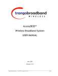
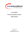
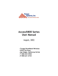
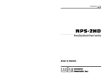
1
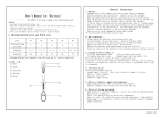
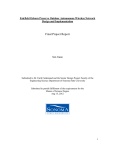
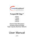
TrangoFOX™
Subscriber Unit
(for Access5830™ Wireless Broadband System)
User Manual
TrangoFOX™ Subscriber Unit User Manual
Overview
This manual covers basic configuration and installation of TrangoFOX Subscriber Units for the Access5830
Wireless Broadband System. The FOX series subscriber units are available three variations.
Model
FOX5800
FOX5300
FOX5800-D
Part #
M5800S-FSU
M5300S-FSU
M5800S-FSU-D
Description
__________
5.8 GHz FOX SU with internal 15 dBi antenna
5.3 GHz FOX SU with internal 15 dBi antenna
5.8 GHz FOX SU for Reflector Dish Part# AD5800-25
TrangoFOX subscriber units work in conjunction with 5.8/5.3 GHz dual-band Access5830™ access points. The
FOX5800 and FOX5800-D also work in conjunction with 5.8 GHz single -band Access5800™ access points.
Please refer to the Access5830 (or Access5800) user manual for detailed information on overall system
implementation, configuration, and management of your point-to-multipoint system. The Access5830 User Manual
also covers many important details of subscriber unit configuration.
FCC Information
This device complies with Part 15 of FCC Rules and Regulations. Operation is subject to the following two
conditions: (1) This device may not cause harmful interference and (2) this device must accept any interference
received, including interference that may cause undesired operation.
This equipment has been tested and found to comply with the limits for a Class B digital device, pursuant to Part 15
of the FCC Rules. These limits are designed to provide reasonable protection against harmful interference in a
residential installation. This equipment generates, uses, and can radiate radio-frequency energy and, if not installed
and used in accordance with these instructions, may cause harmful interference to radio communications. However,
there is no guarantee that interference will not occur in any particular installation. If this equipment does cause
harmful interference to radio or television reception, which can be determined by turning the equipment off and on,
the user is encouraged to correct the interference by one of more of the following measures:
1)
2)
3)
4)
Reorient the antenna;
Increase the separation between the affected equipment and the unit;
Connect the affected equipment to a power outlet on a different circuit from that which the receiver is
connected to;
Consult the dealer and/or experienced radio/TV technician for help.
FCC ID: NCYM5800SFSU
NCYM5800SFSUD
NCYM5300SFSU
Canada: to be announced soon
IMPORTANT NOTE:
Intentional or unintentional changes or modifications must not be made unless under the express consent of the
party responsible for compliance. Any such modifications could void the user’s authority to operate the equipment
and will void the manufacturer’s warranty. To comply with FCC RF exposure requirements, the following antenna
installation and device operating configurations must be satisfied. The antenna for this unit must be fixed and
mounted on outdoor permanent structures with a separation distance of at least two meters from all persons.
Furthermore, it must not be co-located or operating in conjunction with any other antenna or transmitter.
Trango Broadband Wireless
Page 2
TrangoFOX™ Subscriber Unit User Manual
Warranty Information
TrangoFOX Subscriber units are provided with a limited 1 year warranty from date of purchase. Please see
www.trangobroadband.com for complete description of warranty coverage and limitations.
Trango Broadband Wireless
Page 3
TrangoFOX™ Subscriber Unit User Manual
Getting to Know Your Radio
Contents
Each TrangoFOX subscriber unit comes equipped with the radio itself, a power-over-Ethernet (PoE) J-Box, an AC
adapter, and mounting hardware. The FOX5800 and FOX5300 include hardware for wall or pole mounting (except for
wall mount screws and pole-mount hose clamps which are not included). The FOX5800-D is equipped with a dish
(reflector) mounting bracket.
Figure 1. Components of TrangoFOX Subscriber Unit
MOUNTING HARDWARE (FOX5300 & FOX5800)
POWER SUPPLY
(120 VAC - 20 VDC)
- BRACKET, STANDARD
- EXTENDER
- (2) 1/4-20 HARDWARE
DISH MOUNTING HARDWARE (FOX5800-D ONLY)
RADIO
J BOX
(POWER OVER ETHERNET INJECTOR)
- BRACKET, REFLECTOR
- 10-32 X 1" HARDWARE
- 1/4-20 HARDWARE
The radio’s model number and FCC ID are located on the side of the radio.
Figure 2. Radio Side View
TRANGO BROADBAND
WIRELESS
M5800S-FSU
FOX5800 (TM)
REV A
FCC ID: NCYM5800SFSUD
CANADA: XXXXXXXXXX
Trango Broadband Wireless
Page 4
TrangoFOX™ Subscriber Unit User Manual
The TrangoFOX radio is equipped with a removable “boot” and weatherproofing foam insert. Removing the boot and
foam insert reveals the radio’s Ethernet port, LED status lights, reset button, MAC address, and serial number.
Figure 3. Exploded View of Radio, Foam Insert, and Boot
FOX RADIO
FOAM INSERT
BOOT
Figure 4. Bottom View (Boot Removed)
M5300S-FSU
MAC:
S/N:
0001DE FF FF FF
XXXXXXXXXX
|||||||||||
|||||||||||
|||||||||||
TEST DATE:
Trango Broadband Wireless
XX-XX-XX
Page 5
TrangoFOX™ Subscriber Unit User Manual
Getting Started
It is recommended to first provision and test the radio on the bench before deploying in the field. This is a particularly useful
exercise to the novice user.
Connections and Power
?? Remove the “boot” and foam insert from the bottom of the radio.
?? Connect a Cat-5 (straight through) Ethernet cable (we recommend shielded twisted pair) between the ODU (out door
unit) port of the J-box and the RJ-45 connector on the radio. Note that this cable will carry power over Ethernet
(PoE).
?? If connecting to a COMPUTER, use a Cross-Over Ethernet cable from the NET port of the J-box to the computer’s
Ethernet port.
If connecting to a HUB, SWITCH, or ROUTER, use a Straight-Thru cable.
?? Plug the AC adapter into an AC outlet.
Figure 5. Wiring Diagram
FOX RADIO
NETWORK
OR
COMPUTER
INDICATES POWER TO RADIO
INDICATES POWER TO J BOX
CAT-5
USE STRAIGHT-THRU CABLE
IF TO HUB, SWITCH OR ROUTER
CAT-5
STRAIGHT-THRU CABLE
USE CROSS-OVER CABLE IF TO COMPUTER
AC POWER
20 VOLT POWER
SUPPLY
POWER OVER ETHERNET
J BOX
Once the radio is powered, check the LED lights on the bottom of the unit for status information. If the unit is powered,
and not associated with an AP, the ASSOC light should be blinking. The NET LED will light if the unit is connected
to a 100 Base-T Network.
Trango Broadband Wireless
Page 6
TrangoFOX™ Subscriber Unit User Manual
Figure 6. Radio LEDs and Reset Button
M5300S-FSU
MAC:
S/N:
0001DE FF FF FF
XXXXXXXXXX
|||||||||||
|||||||||||
|||||||||||
|||||||||||
TEST DATE:
XX-XX-XX
ACT NET –
RSSI –
LED Guide
Indicates Ethernet Receive/Transmit activity.
This LED lights when connected to a 100 BaseT
network. The LED remains unlit when connected
to a 10 BaseT network
Relative Signal Strength Indicator. See Antenna
Alignment section for more details.
ASSOC – This LED indicates one of four statuses:
1. Off - when there is no power at the
radio.
RESET BUTTON
Pressing the Reset Button (while the unit is
powered) will restore the radio’s factory
default IP address and password. The Reset
Button does NOT reset any other parameters.
2. Blinks once every second - unit is
powered on but opmode is OFF.
3. Blinks twice per second - unit is in
opmode SU and scanning for an AP
4. Solid On - unit is associated with an AP..
Basic Configuration
The TrangoFOX can be configured using either the Command Line Interface (CLI) or the Web Browser (HTTP) interface.
This manual covers the basic HTTP screens from the radio’s built in web server. For a more comprehensive description of the
provisioning and management tools, as well as the complete command line interface reference guide, please see the
Access5830 User Manual.
NOTE: The screenshots presented in this manual are from the FOX5800. Similar screenshots are available on the FOX5300
and FOX5800-D
Browser Interface
The Web browser interface is a powerful and easy-to-use configuration and management tool. Its functionality is a subset of
the commands available in the CLI. To use the browser interface – you must have the following:
?? An Ethernet connection between a PC and the radio
?? Setup your Ethernet PC connection to the subnet that is routable to the radio (default IP address=192.168.100.100)
?? A web browser (i.e. Microsoft Internet Explorer)
In order to use the browser interface – simply connect the radio to a PC, and type the radio’s IP address into the web browser
(i.e. Microsoft Internet Explorer). This will bring up a logon page.
Trango Broadband Wireless
Page 7
TrangoFOX™ Subscriber Unit User Manual
Current Status information is provided in the lower left-hand corner of on all screens. The Current Status shows Base ID, AP
ID, SU ID, Current Opmode, Current Channel and polarization, and its RF link status to the AP(Connected or Disconnected).
Type the password (default trango) and continue. This will bring up the radio’s system information page.
System Information
The Browser Interface features useful Help pages which explain all listed parameters. To access the help pages click on
the Help link.
Hardware Version: Hardware version (Fox5300 is 0003; Fox5800 and FOX800-D is 0004). This parameter is set by
the factory and cannot be altered by the user.
FPGA Version: Field-Programmable Gate Array (FPGA) firmware version. This version will change in the event that
new FPGA version is loaded into the radio.
Trango Broadband Wireless
Page 8
TrangoFOX™ Subscriber Unit User Manual
Firmware Version: Main firmware version. This version will change in the event that new firmware is loaded in the
radio.
Checksum: Firmware checksum is comprised of FPGA firmware and main firmware. Each firmware release has its
own specific checksum provided by manufacturer. Checksum which does not match the number provided by
manufacturer indicates corrupt firmware.
DEVICE ID: MAC address of the radio.
Base ID: See definition in Configuration section.
AP ID: See definition in Configuration section.
SU ID: See definition in Configuration section.
Opmode: Current operation mode of the radio. "SU" indicates transmitting. "OFF" indicates not transmitting.
Default Opmode: See definition in Configuration section.
System Up Time: Time since radio was last rebooted.
IP Address, Subnet Mask and Gateway: See definition in Configuration section.
Telnet Port: User changeable telnet port of radio.
Tftpd: Current status of TFTP daemon. Used for uploading firmware.
Active Channel: See definition in Configuration section.
RF Rx Threshold: See definition in Configuration section.
Tx Power: Current power output of the radio at the antenna port (in dBm). This parameter varies as directed by the
Access Point as a result of AP command “su powerleveling”.
Channel Table (MHz): Shows correlation between channel number and assigned center frequency. Table allows 30
entries. User can make changes to this table under Advanced Setup section. Default table includes channels in both
ISM and U-NII band. Note: lined-out frequencies are not available on this radio.
Scan AP Sequence: See definition of this switch setting in Configuration section.
Broadcast Packet: See definition of this switch setting in Configuration section.
Auto Scanning AP: See definition of this switch setting in Configuration section.
TCP/IP Service for AP: See definition of this switch setting in Configuration section.
TCP/IP Service for Ethernet port (opmode su): See definition of this switch setting in Configuration section.
Remarks: See definition in Configuration section.
Trango Broadband Wireless
Page 9
TrangoFOX™ Subscriber Unit User Manual
Configuration Page
Many of the parameters listed on the System Information page can be changed by the user. Click on Configuration page
for user changeable parameters.
Configuration Page Parameters
Base ID: User definable base station ID (1-127); typically assigned to a group of APs at a particular cell site. The Base
ID in AP must match the Base ID in SU in order for link to be established. This parameter can only be changed while
opmode is "OFF".
AP ID: User definable AP ID (1-255). This parameter is for informational purposes only and does not play a role in the
link establishment. This parameter can only be changed while opmode is "OFF".
SU ID: This parameter is used to uniquely identify the SU within a particular sector. The range is 1-8190. The SUID,
along with its priority type, SU to SU group (if active), CIR, MIR, and device ID must be in the AP's subscriber
database before a link with the AP is established. This parameter can only be changed while opmode is "OFF".
IP Address, Subnet Mask and Gateway: The IP Address, Subnet Mask, and Gateway of this radio for configuration,
and network management purposes. Since this is a layer-II device, these parameters do not play a role in the
establishment of the wireless link.
Default Opmode: Operation mode of the radio after power cycle or reboot. When the radio enters opmode "SU", it will
be transmitting. When the radio enters opmode "OFF" the radio is not transmitting, but can be accessible via the
Ethernet port. The radio can be put into opmode "OFF" regardless of its default opmode by telneting into the radio or
accessing the radio via HTTP within the first 30 seconds after power cycle or reboot.
Switches: Checked means active
Block Broadcast and multicast packets - Block these types of Ethernet packets when active- ARP and DHCP
packets will be passed regardless of this setting.
Trango Broadband Wireless
Page 10
TrangoFOX™ Subscriber Unit User Manual
Auto Scan AP - Active channel and polarization scan sequence below.
TCP/IP Service for AP - Allow TCP/IP access into the SU via the RF link when the SU opmode is "SU".
TCP/IP Service for Ethernet port (opmode su) - Allow TCP/IP access into the SU via the Ethernet port when the
SU opmode is "SU".
Scan AP Sequence: The set of channels and antenna polarizations the SU will automatically scan while it searches for
an AP.
Remarks: A descriptive text field for general use (i.e. the location of the unit). It does not affect system performance.
Save and Activate Settings: Saves to memory any settings that were altered. These settings are then activated. Note:
All changed settings will revert to previous values on power cycle if Save and Activate is not selected.
Activate Opmode: Activates radio's Opmode to "SU"-transmitting. To turn a radio to opmode "OFF", see Default
Opmode.
Reboot System: Reboots the system. Make sure all settings have been saved first.
Advanced Setup Page
In order to optimize your wireless link it may be necessary to reassign channels or change the receivers RF Threshold. To
access these parameters, click on the Advanced Setup link.
Channel Table: Allows user to define a new channel by assigning the center frequency to a specific channel number.
RF Rx Threshold: Sets the receive threshold of the radio. The radio will not process signals received below this level,
so it is very useful for interference mitigation. Setting the Threshold higher (less negative) raises the level of the noise
floor the radio can handle. However, setting the threshold higher will reduce range.
Trango Broadband Wireless
Page 11
TrangoFOX™ Subscriber Unit User Manual
Save and Activate Settings: Saves the setting to FLASH memory and activates setting.
Site Survey
The TrangoFOX includes a site survey tool for detecting RF interference. To utilize this feature, click on the Site
Survey link.
The radio must be in Opmode "OFF" in order to use this feature. Enter the number of minutes desired for the survey,
and select the polarization. Click "Start Survey". A survey of the default channels (6 for ISM band (FOX5800) and 5 for
U-NII band (FOX5300)) will be performed. Results are reported in dBm per channel as average and peak. A channel is
reported to be "Clear" if the peak and average are below the RF RX Threshold by more than 8 dB.
Command Console
In addition to the functionality of the HTTP browser interface, more functions can be performed via the command line
interface (CLI) Most Command Line Interface (CLI) commands may be entered directly from the HTTP Browser’s Command
Console screen. For a complete list of CLI commands, type “help” in the command box and press “Run”.
Trango Broadband Wireless
Page 12
TrangoFOX™ Subscriber Unit User Manual
Telnet
Although most radio functions can be managed via the browser interface, the command line interface (CLI) does provide
slightly more functionality. Most importantly, there are two important functions that must be performed via CLI, that can not
be performed via the web browser interface:
CLI Functions not available in the Browser Interface
?? Change Password (_password command)
?? RSSI Continuous readout (rssi command)
To initiate a Telnet session with the TrangoFOX, first open a command prompt (DOS) session on your PC. Open a Telnet
session by typing
telnet [ip address of radio]
Example:
C:>telnet 192.168.100.100
?
Note: All Trango radios (AP and SU) come factory pre-configured with a defa ult IP address 192.168.100.100.
You will be greeted with current hardware and firmware information and prompted for a password. Type in the password and
press enter.
?
?
Note: The factory default password is trango.
Note: If you can not telnet into the radio, check cable connections, ensure proper use of cross-over vs. straight-through
cable, ensure PC’s subnet is routable to radio’s IP address.
Trango Broadband Wireless
Page 13
TrangoFOX™ Subscriber Unit User Manual
Installation
Hardware
The TrangoFOX is supplied with hardware for pole or wall-mount installations. The diagrams below show a variety of
mounting configurations. Note that a variety of hose clamp mounting straps (not included) may be used depending on
pole diameter. Alternatively 2” U-Bolts (not included) may be used for 2-21/2” diameter poles.
Figure 7. Pole Mount (1” – 2” Diameter)
1/4-20 X 1" HEX HEAD BOLT
FOX RADIO
1"-2" MAST
MOUNTING STRAP (2 PLACES)
(NOT INCLUDED)
1/4-20 KEP NUT
1/4 EXT. TOOTH WASHER (H-9182)
BRACKET (ES-9232)
Trango Broadband Wireless
Page 14
TrangoFOX™ Subscriber Unit User Manual
Figure 8. Wall Mount
1/4-20 X1" HEX HEAD BOLT (2 PLACES)
EXTENDER (ES-9233)
FOX RADIO
NOTE: HARDWARE FOR MOUNTING
BRACKET TO WALL NOT SUPPLIED
BRACKET (ES-9232)
1/4-20 KEP NUT (2 PLACES)
1/4 EXT. TOOTH WASHER (H-9182)(2 PLACES)
Figure 9. FOX5800-D Mounting on AD5800-25 Reflector
FOX RADIO
FEED ARM FROM 18" OFFSET ANTENNA
(AD5800-25)
1/4-20 X 1" HEX HEAD BOLT
DISH MOUNT BRACKET (ES-9231)
1/4-20 KEP NUT
#10 STAR WASHER
10-32 X 1" PAN HEAD SCREW
Trango Broadband Wireless
Page 15
TrangoFOX™ Subscriber Unit User Manual
Figure 10. FOX5800-D / AD5800-25 Reflector Dish on Pole
DISH MOUNTED ON MAST USING U-BOLTS
FOX RADIO (M5800S-FSU-D)
MOUNTED ON DISH
Figure 11. FOX5800-D / AD5800-25 Reflector Dish on Wall
DISH MOUNTED ON WALL (HARDWARE
WILL DEPEND ON MATERIAL OF WALL)
FOX RADIO (M5800S-FSU-D)
MOUNTED ON DISH
Trango Broadband Wireless
Page 16
TrangoFOX™ Subscriber Unit User Manual
Cabling and Grounding Considerations
Shielded twisted pair Cat-5 cable is recommended for all installations.
It is important to provide strain relief and drip loop for STP Cat-5 cables. Strain relief holes are provided on the FOX5800
and FOX5300 mounting bracket for use with cable tie. Create drip loop and strain relief as shown below.
Figure 12. Cat-5 Cable Stain Relief
CABLE TIE
It is advised that the radio be grounded through use of the shielded twisted pair’s drain wires. Prior to crimping the STP Cat-5
cable, strip back approximately 18” of sheathing to expose the drain wires. Cut all wires except the drain wires and then
crimp as normal. Ensure that the drain wires make contact with the RJ-45 metal housing. Twist together the individual drain
wires and connect the other end to a known ground.
Figure 13. Grounding with Drain Wires of Shielded Twisted Pair Cat-5 Cable
TO GROUND
TWISTED DRAIN WIRES
SHIELDED RJ45
SHIELDED CAT5 CABLE
Trango Broadband Wireless
Page 17
TrangoFOX™ Subscriber Unit User Manual
Weather Considerations
It is imperative that the radio be COMPLETELY SEALED when in use. Take care to ensure that the boot and foam
insert are properly installed on the bottom of the radio. Without proper sealing, moisture may enter the radio and
potentially cause damage which will not be covered under warranty.
Access to the radio RJ-45 Port and LED status lights are purposely located at the bottom of the radio to minimize the risk of
water intrusion. Do not mount the radio upside down.
?
Note: The J-Box is not a weatherized device and must be located either indoors or in a weather-protected cabinet.
Antenna Alignment
The four LED RSSI indicators on the bottom of the radio provide a handy alignment tool. If all four LEDs are lit, the
unit is receiving –60 dBm or stronger. If no LEDs are lit, there is not sufficient signal strength to establish a wireless
link.
LIT LEDs
0 LED
1 LED
2 LED
3 LED
4 LED
Signal Strength
-80 dBm
-75 dBm
-70 dBm
-65 dBm
-60 dBm
For more precise RSSI readings utilize the command line interface RSSI tool according to the procedure presented
below.
SU Antenna Alignment Procedure
1. Ensure AP is in opmode “AP”
2. Telnet into the SU
3. Type command RSSI <channel> <polarization> - Example RSSI 3 V (chan. 3, vertical polarization)
4. Telnet session screen will begin a continuous readout of the received signal strength.
5. As you read the RSSI reading, move the antenna in the horizontal and vertical planes until the maximum RSSI
reading is achieved. For short links you can expect an RSSI of – 60 dBm or better. For longer links and RSSI
of –75 dBm is acceptable. Any RSSI of less than –80 dBm may be too weak for the radios to reliably associate
and pass data.
6. If it is not possible to receive an adequate RSSI reading, it may be necessary to reorient the AP (up/down,
left/right), to increase the output power of the AP, or to move the SU to a location with better line-of-sight
conditions to the AP.
Once you are satisfied with the RSSI reading, tighten down the SU in the optimum position. To stop the RSSI
continuous readout, hit SPACE ENTER.
? Note: SU RSSI (both LED and command line) will provide signal strength from any device transmitting on
the chosen frequency. In order to identify the source of the signal as the AP, use the APSEARCH command.
Syntax: apsearch <seconds> <channel > <polarization>
Example: apsearch 30 3 v (run search for 30 seconds on channel 3, vertical polarization).
This command will identify any AP by AP number which is within range and broadcasting on the specified
channel.
Trango Broadband Wireless
Page 18
TrangoFOX™ Subscriber Unit User Manual
Specifications
Radio Transmit Specifications
FOX5800 and FOX5800-D
Frequency Range: 5.736 to 5.836 GHz adjustable in 1 MHz channel increments
Default Channels Channel 1: 5.736 GHz
Channel 2: 5.756 GHz
Channel 3: 5.776 GHz
Channel 4: 5.796 GHz
Channel 5: 5.816 GHz
Channel 6: 5.836 GHz
FOX5300
Frequency Range 5.260 to 5.340 GHz adjustable in 1 MHz channel increments
Channel 7: 5.260 GHz
Channel 8: 5.280 GHz
Channel 9: 5.300 GHz
Channel 10: 5.320 GHz
Channel 11: 5.340 GHz
RF Conducted Power:
EIRP Max:
Freq. Stability:
Freq. Plan:
Modulated BW:
2nd Harmonic atten:
LO Supression:
Symbol Rate:
Error Correction:
Modulation:
FOX5800:
Max: +21 dBm +/ - 2 dB
Min: -12 dBm +/- 2 dB
FOX5800-D:
Max: +21 dBm +/ - 2 dB
Min: -12 dBm +/- 2 dB
FOX5300:
Max: +15 dBm +/ - 2 dB
Min: -12 dBm +/- 2 dB
FOX5800
FOX5800-D
FOX5300
+36 dBm
+46 dBm (with AD5800-25-D Reflector)
+30 dBm
.00025 % PLL Stabilized (2.5 ppm) over temp
Single upconversion, 480 MHz IF
22 MHz (null to null, 20 dB)
Per CFR47 part 15.205
Per CFR47 part 15.205
1.375 MSPS
None
1 Mbps DBPSK for header, 11 Mbps CCK spread spectrum for payload
Receiver Section (check these figures)
Cascade Noise Figure:
< 6 dB
Sensitivity:
- 82 dBm typical-1600 byte packet
(1E10-6 BER)
- 87 dBm typical-64 byte packet
Adj. Channel Rejection: > 20 dB for 10 % PER
Image Rejection:
> 60 dB for 10% PER
Frequency Plan:
Single conversion, IF at 480 MHz
LO stability:
.00025% PLL stabilized (+/-2.5ppm) over temperature range
Data Input Section
Trango Broadband Wireless
Page 19
TrangoFOX™ Subscriber Unit User Manual
Data Rate (User):
Format:
Ethernet packet:
Power
Input Voltage:
Up to 10 Mbps Sustained throughput
10/100 BaseT IEEE 802.3 Ethernet compliant
Up to 1600 byte long packets
Input voltage range at unit is 10.5 VDC to 24 VDC max
Power is supplied on Ethernet cable using junction box provided with up to 330 foot 24 AWG STP cable.
Current Cons.:
400 mA in transmit mode at max power using 20 V standard adapter (8 W)
Data Output Section
Data Rate (User):
Format:
Ethernet Protocols:
10 Mbps Maximum sustained throughput
10/100 BaseT IEEE 802.3 Ethernet compliant
TCP/IP, Telnet, TFTP, UDP, HTTP
Physical Interfaces
LAN Interface:
Power:
Shielded RJ45 connector
Carried on 4 unused pins of Ethernet cable
Mechanical and Environmental
General Material:
High Temp ABS/Polycarbonate Enclosure
Size:
9.2”x4.25”3.1”
Weight:
1.5 lb (radio)
Mounting:
Polycarbonate Wall/Pole mount bracket
Environmental
Operating Temp:
Storage:
Humidity:
NEMA Rating:
-40 to 60 deg C
-40 to 85 deg C
100 % When sealed properly
NEMA 4
Standard Power Supply
20 Volt DC Power adapter and J-Box supplied with product.
Type:
Linear wall mount transformer
Input:
120 VAC
Output:
20 VDC +/- 1 V
Max current:
1200 mA
FCC Compliance
The transceiver complies with the following regulations:
FOX5800 and FOX5800-D: FCC 15.247 Spread Spectrum transmitter - 5.725 to 5.85 GHz – EIRP = +36 dBm max
FOX5300: FCC 15.407(2) U-NII Band 2 transmitter - 5.25 to 5.35 GHz – EIRP = +30 dBm max
Subpart B
Class B Digital device verification
Subpart C
FCC 15.203 Antenna connection requirement – non-standard connection
FCC 15.209 Unwanted emissions below 1GHz FCC 15.207(a) AC conducted emissions 450Khz to 30 MHz
FCC 15.205 Restricted bands (LO and harmonics)= 54 dBuV average @3 meters
Trango Broadband Wireless
Page 20
TrangoFOX™ Subscriber Unit User Manual
FOX5800 and FOX5300 Antenna Specifications
Type
Patch Array Antenna
Polarization
Vertical, Horizontal electronically selectable
Range
FOX5800: 4 Miles (LOS) from Access5830 AP with 10 dB fade margin.
FOX5300: 2 Miles (LOS) from Access5830 AP with 10 dB fade margin.
Frequency
5.2 to 5.9 GHz
Gain
+15 ? 1 dBi
Azimuth Beamwidth
32?
Elevation Beamwidth 18?
FOX5800-D Antenna Specifications (when mounted on AD5800-25 Reflector Dish)
Type
DSS Style Dish Antenna
Polarization
Vertical, Horizontal electronically selectable
Range
10 Miles (LOS) from Access5830 AP with 10 dB fade margin.
Frequency
5.7 to 5.9 GHz
Gain
+25 dBi
Azimuth Beamwidth
9?
Elevation Beamwidth 9?
Trango Broadband Wireless
Page 21