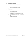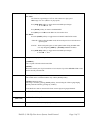
1
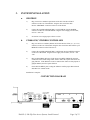
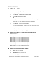
12843 Foothill Blvd. Suite C Sylmar, California 91342 V: 818.898.3380 F: 818.898.3360 [email protected] Model No. 2044CL-L (& 2044CL-L-T) 300 CLIP FAST ACCESS SYSTEM Louth Protocol USER MANUAL Ver. 1.52 TABLE OF CONTENTS 1. REVISION HISTORY GETTING STARTED . . . 2. 3. A. B. 4. 5. 6. A. B. 7. A. B. 8. 9. A. B. 10. 11. SYSTEM DESCRIPTION DEFINITIONS SYSTEM INSTALLATION SHOTBOX ST400-S/SM, VTR/DDR CONTROLLER VIDEO SERVER SETUP LOAD A CLIP LEARN A CLIP OR CLIP COMBINATION ON THE ST400 ON THE SHOTBOX RECALL A CLIP OR CLIP COMBINATION ON THE ST400 ON THE SHOTBOX RECUE CLIP CLEAR CUE POINTS ON THE ST420 SHOTBOX ON THE ST400 LOOP CLIP ON THE ST400 PLAY CLIP SEGMENT ADVANCED FEATURES . . . 14. 15. 16. 17. 18. 19. CREATE A CLIP SHOTBOX SHOTKEY MAPPING TO SHOTLIST LOCATIONS SHOTBOX CONTROL SWITCHES VIEW SHOTKEY ASSIGNMENTS ON THE SHOTBOX REALIGN GANGED CHANNELS CREATE CUE POINT LABELS ON THE ST400 REFERENCE . . . 20. 21. 22. A. B. 23. A. 24. 25. SETUP MENU FUNCTION TABLE SPECIFICATIONS ST400 ST420 (SHOTBOX) TROUBLESHOOTING ST420 TROUBLESHOOTING KEY LAYOUT DNF CONTROLS LIMITED WARRANTY 3 4 4 4 5 5 5 6 6 7 7 8 8 8 8 8 8 9 9 10 10 10 11 11 11 11 12 12 12 12 12 13 13 16 18 18 19 21 21 22 23 Manual Version......................................…...................1.52 092007 Document ID.................................... 2044CL-L User Manual.doc 2044CL-L, 300 Clip Fast Access System, Louth Protocol Page 2 of 23 1. REVISION HISTORY 120303 1.0 Original document. 011204 1.1 Corrected Key Layout. 120104 1.2 Updated ST420 Troubleshooting section. 012005 1.3 Revised to conform to software V5.3. 063005 1.4 Added Video Reference instructions 102705 1.5 Update to current manual convention. 092706 1.51 Updated GPI connector specifications. 092007 1.52 . Added DSK setup chart. 2044CL-L, 300 Clip Fast Access System, Louth Protocol Page 3 of 23 Getting Started . . . 2. SYSTEM DESCRIPTION The 2044CL system includes DNF’s most robust controller, the ST400, with the industry’s premiere Shotbox, the ST420. The ST400 controls up to 6 video channels individually or ganged. It features full transport functionality. The LCD buttons on the Shotbox display clip names and delivery instant access to video clips on up to 6 channels. The assign-able keys on the ST420 Shotbox allow clip names to be organized on ten different banks of keys for easy access. The 2044CL provides instant access to fill clip and key clip combinations with the press of one key. The 2044CL-L supports VDCP protocol and requires that the Video Server be controllable under VDCP Protocol. The 2044CL provides instant access to existing video clips stored in the Grass Valley Group PROFILE, the Leitch VR, and other Video Servers supporting VDCP Protocol. DEFINITIONS Throughout this document, DDR, VDR & Video Server will be referred to collectively as “Video Server.” The ST400-S/SM will be referred to as ST400. The ST420 SHOTBOX will be referred to as “Shotbox.” SHOTKEY refers to the 1-30 switches on the Shotbox. Words surrounded by brackets, for example, [ENTER], are keys on the ST400 or the SHOTBOX. [XXX] + [XXX] means hold the two keys down simultaneously. The 6 keys directly below the display are referred to as “Softkey.” For example {GANG}. Their function changes as indicated on the last line of the display. Shotkeys and Cue Points refer to the same memory locations. Both terms are interchangeable. 2044CL-L, 300 Clip Fast Access System, Louth Protocol Page 4 of 23 3. SYSTEM INSTALLATION a. b. SHOTBOX 1) Plug one end of a standard 9-pin, RS422 serial cable into the OUTPUT connector on the rear of the Shotbox. Plug the other end of the cable into the “SHOTBOX” connector on the rear of the ST400. 2) Connect the supplied POWER SUPPLY, AULT#SW300, into the POWER connector on the rear of the SHOTBOX. Plug the Power Supply into an outlet, 90 VAC - 240 VAC. 3) See Section 19 to assign proper software version. ST400-S/SM, VTR/DDR CONTROLLER 1) Plug one end of a 9-conductor, RS422 serial cable into the VTR1 (2, 3, 4, 5 or 6) connector on the rear of the ST400. Plug the other end of the cable into the 9-pin REMOTE connector on the Video Server. 2) Connect the supplied POWER SUPPLY, APX#4108, into the POWER connector on the rear of the ST400. Plug the Power Supply into an outlet, 90 VAC - 240 VAC. 3) Plug in a Black Burst Reference Video Source into REF. VIDEO IN connector on the back of the ST400 using a BNC cable to utilize the capture function or the gang function. Video Reference must be connected for frame accurate playout of ganged channels, and for Capture function. 4) Check SETUP MENU prior to using the ST400 to confirm proper Record mode and other User settable modes. Installation is complete. CONNECTION DIAGRAM 2044CL-L, 300 Clip Fast Access System, Louth Protocol Page 5 of 23 4. VIDEO SERVER SETUP a. Select Louth Broadcast communications protocol on the VIDEO SERVER to be controlled. b. Assign a serial port on the VIDEO SERVER through which the ST400 will control it. NOTES: In Louth mode, the VIDEO SERVER ONLY allows Full Record. INSERT and ASSEMBLE record modes are disabled. Setup is complete 5. LOAD A CLIP a. Select a VTR by pressing VTR [1], [2], [3], [4], [5], or [6]. b. Press [CLIP LIST] to view the list of CLIP IDs that are resident on the Video Server. The CLIP LIST indicator will turn on. c. Press {CREATE} to create and load a new clip. (Creating a clip is described in the CREATING A CLIP section.) OR Turn the Wheel to view the existing CLIP IDs on the video server. Turn the Wheel clockwise to scroll forward, or counter-clockwise to scroll backward, through the list of available CLIPs. Press the [LAST] key to move back one page. Press the [NEXT] key to move ahead one page. Press [ALT] + [LAST] or [ALT] + [NEXT] to move 50 clips, back or ahead for long lists. OR Press [ENTER] to manually enter a CLIP ID using the ST400 numeric keypad, PC keyboard or QWERTY keyboard on the shotbox. d. Press [LOAD] to load the entered CLIP ID for playout. e. Repeat steps a. thru d. to load clips on desired VTRs. 2044CL-L, 300 Clip Fast Access System, Louth Protocol Page 6 of 23 6. LEARN A CLIP OR CLIP COMBINATION a. ON THE ST400 1) Press VTR [1], [2], [3], [4], [5], or [6]. 2) Load a clip on the selected channel. See section LOAD A CLIP. 3) Use the transport functions to view the clip. Press [IN] to mark an IN point. The IN LED will blink. On recall, the clip will cue to the IN time, not the beginning of the clip and the LED will stay on steady. Optional- Press [OUT] to mark an OUT point. The OUT LED will blink. On recall, the clip will play to the OUT point then stop. To delete an IN or OUT point, press and hold [DEL], then press [IN] or [OUT]. The IN/OUT LED will turn off. If no IN point is marked, the current location of the clip will be learned as the IN point. 4) For GANGs, repeat steps 1), 2) and 3) for each channel. Then press the {GANG} softkey. Press VTR [1], [2], [3], [4], [5], or [6] to add the VTR to the GANG. The VTR LED will turn on. Press the VTR key again to remove it from the gang. The VTR LED will turn off. Press [ESC] to exit GANG mode. The LED of all GANGed VTRs will turn on. 5) Select the desired Cue Point by pressing [NEXT CUE], [LAST CUE] or by manually entering the Cue Point using the numeric keypad, followed by [ENTER]. The selected Cue Point number is shown on the bottom part of the display. 6) Press [SHIFT] + [MARK] to initiate the Learn. The display will show: “Select VTRs to learn:--------” 7) Select the VTRs to be learned by pressing VTR keys [1], [2], [3], [4], [5], and/or [6]. 8) Press {LEARN} or [MARK] to complete the Learn process. NOTE: Learn will overwrite the previous contents of the Cue Point. Press [ESC] at anytime to escape without LEARNing. 2044CL-L, 300 Clip Fast Access System, Louth Protocol Page 7 of 23 b. ON THE SHOTBOX 1) Press [LEARN]. The LEARN indicator will turn on. 2) Select the desired BANK by pressing BANK [1], [2], [3], [4], [5], [6], [7], [8], [9], or [0]. 3) Press the desired Shotkey to complete the learn process. The learned CLIP ID is displayed on the Shotkey. LEARN will save the CLIP ID on the channel selected in step #1, the IN and OUT points marked in step #2, and the GANG configuration selected in step #3. NOTE: LEARN will overwrite the previous contents of the Shotkey. 3) Press [LEARN] at anytime to escape without LEARNing. 7. RECALL A CLIP OR CLIP COMBINATION a. ON THE ST400 1) Select the desired Cue Point by pressing [NEXT CUE], [LAST CUE] or by manually entering the Cue Point using the numeric keypad. The selected Cue Point number is shown on the bottom of the display. 2) Press [LOAD] on the ST400. The ST400 will automatically load the learned clips on the learned VTRs. Cue the clips to the learned IN time. b. 8. 9. ON THE SHOTBOX 1) Select the desired BANK by pressing BANK [1], [2], [3], [4], [5], [6], [7], [8], [9] or [0]. The Shotkeys will display the assigned CLIP IDs for the selected bank. 2) Press the desired Shotkey. The selected clip or clip combination will be loaded on the learned channels, and cued to the learned IN point. The learned OUT point and GANG mode will be set. RECUE CLIP a. Press [RECUE]. If an IN Point is marked (the IN indicator is on), the clip will RECUE to the IN Point. b. Press {CUE OUT} to cue to the marked OUT point. CLEAR CUE POINTS 2044CL-L, 300 Clip Fast Access System, Louth Protocol Page 8 of 23 a. ON THE ST420 SHOTBOX 1) Select the desired BANK by pressing the desired bank key. 2) Press and hold the [SHIFT] key. 3) Press the desired Shotkey to be cleared. After the cue point is cleared, the Shotkey will be blank. OR b. ON THE ST400 1) Select the cue point to be cleared using [NEXT CUE], [LAST CUE], or manually entering the cue point number. 2) Press [SHIFT] + [LEARN]. The {CLR-CUE} softkey will be displayed on the bottom of the display. 3) Press the {CLR-CUE} softkey to clear the cue point. The cue point will be cleared and the display will return to the normal screen. OR Press [ESC] to escape without clearing. 2044CL-L, 300 Clip Fast Access System, Louth Protocol Page 9 of 23 10. LOOP CLIP ON THE ST400 a. Load the clip using CLIP LIST, or recall a cue point. (The clip MUST be loaded from the 2044CL.) b. Optional: Set an IN Point and/or OUT Point. Jog/Shuttle to the desired IN point. Press [IN]. Jog/Shuttle to the desired OUT point. Press [OUT]. OR Press [SHIFT] + [IN]. Manually enter the IN time on the numeric keypad. Press [ENTER]. Press [SHIFT] +[OUT]. Manually enter the OUT time on the numeric keypad. Press [ENTER]. c. Press [LOOP ENABLE]. The clip will immediately start looping. NOTE: If the CLIP ID ends with an asterisk (“*”), it will automatically loop when either [LOOP ENABLE] or [PLAY] is pressed. 11. PLAY CLIP SEGMENT a. Set an IN Point and OUT Point. Jog/Shuttle to the desired IN point. Press [IN]. The IN LED will blink. Jog/Shuttle to the desired OUT point. Press [OUT]. The OUT LED will blink. OR Press [SHIFT] + [IN]. Manually enter the IN time on the numeric keypad. Press [ENTER]. Press [SHIFT] + [OUT]. Manually enter the OUT time on the numeric keypad. Press [ENTER]. b. Learn the segment into a cuepoint. b. Recall a cuepoint. The IN and OUT LEDs turn on steady. c. Press [PLAY]. The clip will play to the OUT point, then stop. NOTE: If IN & OUT LEDs blink, the clip will not stop at the OUT point. It will only stop at the OUT point of LEDs are on steady. 2044CL-L, 300 Clip Fast Access System, Louth Protocol Page 10 of 23 Advanced Features . . . 14. CREATE A CLIP a. In the Setup Menu, configure Louth port as Input Port. b. Press [CLIP LIST]. c. Press {CREATE}. The display will show the default CLIP ID. d. Press [LOAD] to accept the default CLIP ID. OR Manually enter an ID with a maximum of 32 characters from the ST400 numeric keypad. OR Manually enter an ID with a maximum of 32 characters from a PC keyboard. e. Press {CREATE}. The clip will be created and loaded. If the entered CLIP ID already exists, a warning message will be displayed. Press any key to rename clip. Press [RECORD] to start recording. OR Press [ESC] to exit without loading the existing clip. 15. SHOTBOX SHOTKEY MAPPING TO SHOTLIST LOCATIONS The Shotkeys on the Shotbox access the cue point locations in the ST400 as follows: BANK 0, Shotkeys 1 Æ 30 access cue point locations 001 Æ 030. BANK 1, Shotkeys 1 Æ 30 access cue point locations 101 Æ 130. BANK 2, Shotkeys 1 Æ 30 access cue point locations 201 Æ 230. BANK 3, Shotkeys 1 Æ 30 access cue point locations 301 Æ 330. BANK 4, Shotkeys 1 Æ 30 access cue point locations 401 Æ 430. BANK 5, Shotkeys 1 Æ 30 access cue point locations 501 Æ 530. BANK 6, Shotkeys 1 Æ 30 access cue point locations 601 Æ 630. BANK 7, Shotkeys 1 Æ 30 access cue point locations 701 Æ 730. BANK 8, Shotkeys 1 Æ 30 access cue point locations 801 Æ 830. BANK 9, Shotkeys 1 Æ 30 access cue point locations 901 Æ 930. 16. SHOTBOX CONTROL SWITCHES a. [PLAY]: Plays out the selected clip. b. [RECUE]: Returns to the IN point of the clip. c. [STOP]: Stops playout of the clip. 2044CL-L, 300 Clip Fast Access System, Louth Protocol Page 11 of 23 17. VIEW SHOTKEY ASSIGNMENTS ON THE SHOTBOX a. Press [VIEW]. The VIEW LED indicator will turn on. b. Select the desired BANK by pressing the appropriate bank key. c. Press and hold the desired Shotkey. d. The LCD display on the Shotkeys will show the current assignment of all 6 VTRs for the pressed Shotkey. e. Release the Shotkey when done viewing. f. Repeat steps a through e. 18. REALIGN GANGED CHANNELS When the channels are Jogged/Shuttled/Slomoed in gang, they may drift apart. To bring the channels back to their initial offsets, press [SHIFT] + [STOP]. 19. CREATE CUE POINT LABELS Use LABELS mode to assign meaningful names to cue points. Rather than viewing cryptic CLIP IDs on the Shotkeys, LABELS provides a faster and easier method to select cue points. If different parts of the same clip are assigned to many Shotkeys, LABELS allows a unique name to be assigned to each Shotkey. ON THE ST400 a. In Setup Menu, turn LABEL MODE on. b. Select cue point to label. c. Press the [LABEL] key. d. Manually enter a label, up to 8 characters in length, using the numeric keypad, ST420 Shotbox QWERTY keyboard, or PC keyboard. e. Press the [LOAD] shotkey on the Shotbox to assign the entered label to the selected cue point. OR [ENTER] on the ST400. OR [ENTER] on the PC keyboard. OR [NEXT CUE] or [LAST CUE]. NOTE: Labels are saved in non-volatile memory in the ST400, not in the Shotbox. They are not saved in the video server. 2044CL-L, 300 Clip Fast Access System, Louth Protocol Page 12 of 23 Reference . . . 20. SETUP MENU Press [MENU]. The MENU indicator will turn on. The display will show the following parameters with their current settings. Turn the wheel to select a menu option. Press the {CHANGE} softkey to modify the current setting, then press {BACK} after making selection. Press the {EXIT} softkey to exit the Setup Menu. PARAMETER LOUTH (PER/VTR) DESCRIPTION Enter the controlled channel’s Louth port number (1 - 9) on the numeric keypad. Then press the {INPUT} or {OUTPUT} softkey. An INPUT is indicated by ‘-‘ before the port number. To CREATE (RECORD) clips, an INPUT channel must be selected. To playout CLIPS, an OUTPUT channel must be selected. Enter ‘0’, to turn off the port. PROTOCOL (PER/VTR) {LOUTH} or {BVW}. STANDARD {NTSC} or {DF} or {PAL} WIND MODE {HOLD} (Fast wind is maintained only while key is depressed.) OR {LATCH} (Fast wind is initiated and maintained with momentary key press.) {SPEED} Press the softkey to change the speed setting (3.9, 6.0, 8.1, 10.0, 23.7). EXTENDED IDs {ON} – Allow up to 32-character CLIP IDs. {OFF} – Allow up to 8-character CLIP IDs. RECORD MODE (PER/VTR) Press a softkey to select the desired record mode: Lockout or Crash. 2044CL-L, 300 Clip Fast Access System, Louth Protocol Page 13 of 23 SLOMO Press the {TBAR} (or {WHEEL}) softkey to select the T-bar or wheel for slomo. For T-bar: The T-bar has a speed range of 0 Æ 2x with a detent at 1x play speed OR a range of 0 Æ 1x (detent at 1x play speed). Press {SPD-RNG} softkey to toggle between SLOMO speed ranges: -1 Æ +2x OR 0 Æ +2x. Press {BACK} softkey to return to SLOMO MENU. Press [ESC] to exit OR turn the Wheel to select another item. For Wheel: Press the {PRSET} softkey to toggle between UPDATE and STATIC modes. UPDATE: When exiting SLOMO mode, the last used speed is saved in the Preset Speed register. STATIC: The Preset Speed register is NOT updated when exiting SLOMO mode. It is only changed by [SHIFT] + [SLOMO] (PRESET SLOMO). Press {SPD-RNG} softkey to toggle between SLOMO speed ranges: 0 Æ 2x OR -1 Æ 2x. RECALL MODE Press {NORMAL} or {REDIR} (redirect). {NORMAL} The cue point will load on the learned VTR. {REDIR} When one and only one clip is learned into a Cue Point, the Clip will be REDIRECTED to load On the currently selected VTR. GANG MODE {PERM} Permanent Gang – The GANG can be created and undone only with the {GANG} softkey. {TEMP} Temporary Gang – The Gang is created by pressing {GANG} softkey, then selecting the VTRs to gang/ungang. Quickly undo the GANG by pressing any VTR key. Video Reference must be connected for frame accurate playout of ganged channels. DISK PREROLL See Disk Preroll Setup Chart PLAY PREROLL (PER/VTR) See Disk Preroll Setup Chart REC. DELAY Enter frames on keyboard, then {OK} or [ENTER]. 2044CL-L, 300 Clip Fast Access System, Louth Protocol Page 14 of 23 PREROLL DESTINATION REF. VIDEO {SERVICE} Enter frames and seconds on keyboard, then {OK} or [ENTER] Select VTR for destination (during Record). {ON} or {OFF} The ST400 will lock to external reference. Required for accurate ganged events. {DEFAULTS} {CLEANUP} {BACK} {DEFAULTS} Set ST400 to factory defaults. Follow the prompts on the display. Press {YES} to continue or press {NO} to exit without changing ST400. {CLEANUP} Clears all cue points in all banks. Follow the prompts on the display. {BACK} Return to prior menu item. DISK PREROLL SETUP CHART Server Menu Settings Disk Preroll Play Preroll 360 systems V1 10 frames Avid Airspeed OFF 8 frames Doremi V2 16 frames EVS XT V1 2 frames GV PDR, XP V2 40 frames GV K2 V2 10 frames GV M-series, Turbo V2 20 frames Leitch NX400 OFF 11 frames Leitch NX3600, NX4200 OFF 6 frames V1 20 frames Omneon 2044CL-L, 300 Clip Fast Access System, Louth Protocol Page 15 of 23 21. FUNCTION TABLE Function Key Press Description CUE TO OUT POINT {CUE OUT} If OUT point is marked, cue to the OUT point. FFWD [FFWD] Press and hold to FFWD. Release key to stop. Set WIND SPEED in MENU. GO TO ENTERED TIME [SHIFT] + [RECUE] To search, manually enter the desired time on the ST400’s numeric keypad. Press [ENTER] or [RECUE]. GANG SETUP {GANG} Individually press the VTR keys to be included in the gang. The LED above the key will turn on. Press the VTR key again to remove from gang; the LED above the key will turn off. Press [ESC] to exit. Upon exiting, all members of the gang will have their VTR LEDs turned on. The flashing LED shows which VTR is currently selected. JOG [JOG] Select JOG mode and enable Wheel. LABEL [LABEL] Press [LABEL]. Enter a label (name) for the selected Cue Point. Use the Shotbox or PC keyboard. Press [ENTER] on PC keyboard or ST400. Press [LOAD] on Shot Box. LAST CUE [LAST] Step to the previous Cue Point Location. NEXT CUE [NEXT] Step to the next Cue Point Location. RECORD [REC] Places VTR into the Record mode selected by RECORD MODE in the SETUP MENU. Press [RECORD] or [RECORD] + [PLAY]. REWIND [RWD] Press and HOLD to rewind. Release key to stop. Set WIND SPEED in MENU. SHUTTLE [SHUTTLE] Select SHUTTLE mode and enable Wheel. SLOMO [SLOMO] Press [SLOMO] to slo-mo the VTR. Turn the Wheel (or move the T-bar, if available) to change the play speed. Press [SLOMO] to STILL frame OR press any transport key to exit SLOMO. 2044CL-L, 300 Clip Fast Access System, Louth Protocol Page 16 of 23 STOP [STOP] Press once to STILL frame VTR. Press again to put VTR into STOP mode. TIME MODE SELECT [TIME MODE] Press to toggle between Timecode (TC), VITC (VT) or Tape Timer (TM) display modes on a VTR and between Remaining Time (RT) and Elapsed Time (ET) on a Video Server. PLAY [PLAY] If an OUT point is marked, play to the OUT point and stop. If no OUT point is marked, play normally. If the clip ID ends with an “*”, the clip will loop continously. RECUE [RECUE] If the IN point is marked, cue to the IN point REALIGN GANGED CHANNELS [SHIFT] + [STOP] Search ganged channels to the appropriate time to resynchronize them. STEP 1 FRAME FORWARD [SHIFT] + [FFWD] Moves the video forward by 1 frame. STEP 1 FRAME BACK [SHIFT] + [REWIND] Moves the video back by 1 frame. 2044CL-L, 300 Clip Fast Access System, Louth Protocol Page 17 of 23 22. SPECIFICATIONS a. ST400 Power: 90 VAC to 265 VAC adapter supplied with IEC connector APX Model #AP4108 +5v @ 4A, +12v @ 1.0A, -12V @ 0.6A Size: [L” x W” x H”] 12 3/4” x 8” x 1 3/4” (front) 3 5/8” (rear) [8 5/8” high to top of display] Weight: 10 lbs. Rear Panel Connectors: VTR1, 2, 3, 4, 5, 6 GPI Power SHOTBOX PBIO Keyboard Ref. Video In Ground Display: Easy to read, back-lit LCD display Jog/Shuttle Wheel: With mechanical detents (All DB9F) (DBF25F) (DB9M) (DB9F) (DB9F) (6-pin mini DIN) (BNC) #6 Threaded stud RS422 SERIAL CONNECTOR 9-Pin D-Type, Female (DB9F) Pin # 1 2 3 4 5 Frame Ground Receive A- Í Transmit B+ Î Transmit Common Spare 6 7 8 9 Receive Common Receive B+ Í Transmit A- Î Frame Ground 6 7 8 9 +5 VDC Ground Ground Ground POWER CONNECTOR 9-Pin D-Type, Female (DB9M) Pin # 1 2 3 4 5 +5v DC +5v DC Ground +12 VDC –12 VDC 2044CL-L, 300 Clip Fast Access System, Louth Protocol Page 18 of 23 GPI IN/OUT CONNECTOR 26-Pin D-Type, Female (D26HDF) b. Pin # OUT 1 2 3 4 5 6 7 8 9 10 11 12 13 OUT OUT OUT OUT OUT OUT OUT OUT IN IN IN IN IN/ Function Pin # OUT GPO 0 – No function GPO 1 – No function GPO 2 – No function GPO 3 – No function GPO 4 – No function GPO 5 – No function GPO 6 – No function GPO 7 – No function Ground PLAY STOP RECUE NEXT CUE 14 15 16 17 18 19 20 21 22 23 24 25 26 IN IN IN/ Function LAST CUE RECALL CUE No Function No Function Ground +5V +5V No Connection No Connection No Connection No Connection No Connection Ground ST420 (SHOTBOX) Power: 90 VAC to 265 VAC adapter supplied with IEC connector AULT Model #SW300 +5v @ 3.5A, +12v @ 2A, -12v @ 0.8A Size: [L” x W” x H”] 11.5” x 6 .5” x 1.75” (front) 3.5” (rear) Weight: 4 lbs. Rear Panel Connectors: Out GPI Power Aux (DB9F) (DBF15F) (DB9M) (DB9F) RS422 SERIAL CONNECTOR 9-Pin D-Type, Female Pin # 1 2 3 4 5 Frame Ground Transmit A- Î Receive B+ Í Receive Common Spare 6 7 8 9 Transmit Common Transmit B+ Î Receive A- Í Frame Ground 6 7 8 9 No Connection Ground Ground Ground POWER CONNECTOR 9-Pin D-Type, Male Pin # 1 2 3 4 +5v DC +5v DC Ground No Connection 2044CL-L, 300 Clip Fast Access System, Louth Protocol Page 19 of 23 5 No Connection 2044CL-L, 300 Clip Fast Access System, Louth Protocol Page 20 of 23 23. TROUBLESHOOTING a. ST420 TROUBLESHOOTING a. All Shotkeys are RED - No communication with the ST400. b. All Shotkeys are DARK - No communication between the ST400 and the Video Server. c. Set the ST420 version to match the ST400: On the ST420 V4.02, V4.03, V4.12, V4.13: 1) Press [SHIFT] + [STOP] + [PLAY]. The key that displays the current version is RED. 2) The ST420 displays: “ST300/400 SELECT” [ST300 V2.X] [ST300 V3.X] [ST400 2044CL-O] [ST400 2044CL-L] 3) Press the [ST400 2044CL-L] key for communication with the ST400. On the ST420 V4.04, V4.14 and above: 1) Press [SHIFT] + [STOP] + [PLAY]. The key that displays the current version is RED. 2) The ST420 displays: “ST300/400 SELECT” [ST300 V2.X] [ST300 V3.X] [ST400 V4.X – V5.20] [ST400 V5.30 and up] 3) Press a key that corresponds to the version of the ST400 that you are using. 2044CL-L, 300 Clip Fast Access System, Louth Protocol Page 21 of 23 24. KEY LAYOUT 2044CL-L, 300 Clip Fast Access System, Louth Protocol Page 22 of 23 25. DNF CONTROLS LIMITED WARRANTY DNF Controls warrants its product to be free from defects in material and workmanship for a period of one (1) year from the date of sale to the original purchaser from DNF Controls. In order to enforce the rights under this warranty, the customer must first contact DNF’s Customer Support Department to afford the opportunity of identifying and fixing the problem without sending the unit in for repair. If DNF’s Customer Support Department cannot fix the problem, the customer will be issued a Returned Merchandise Authorization number (RMA). The customer will then ship the defective product prepaid to DNF Controls with the RMA number clearly indicated on the customer’s shipping document. The merchandise is to be shipped to: DNF Controls 12843 Foothill Blvd., Suite C Sylmar, CA 91342 USA Failure to obtain a proper RMA number prior to returning the product may result in the return not being accepted, or in a charge for the required repair. DNF Controls, at its option, will repair or replace the defective unit. DNF Controls will return the unit prepaid to the customer. The method of shipment is at the discretion of DNF Controls, principally UPS Ground for shipments within the United States of America. Shipments to international customers will be sent via air. Should a customer require the product to be returned in a more expeditious manner, the return shipment will be billed to their freight account. This warranty will be considered null and void if accident, misuse, abuse, improper line voltage, fire, water, lightning or other acts of God damaged the product. All repair parts are to be supplied by DNF Controls, either directly or through its authorized dealer network. Similarly, any repair work not performed by either DNF Controls or its authorized dealer may void the warranty. After the warranty period has expired, DNF Controls offers repair services at prices listed in the DNF Controls Price List. DNF Controls reserves the right to refuse repair of any unit outside the warranty period that is deemed non-repairable. DNF Controls shall not be liable for direct, indirect, incidental, consequential or other types of damage resulting from the use of the product. ### 2044CL-L, 300 Clip Fast Access System, Louth Protocol Page 23 of 23