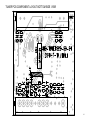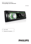
1
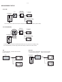
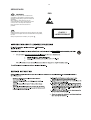
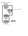
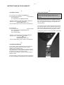
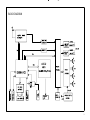
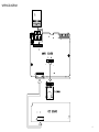
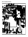
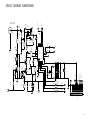
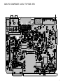
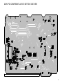
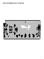
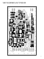
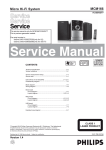
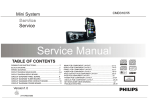
Car audio system
CE130/ 55/51, CE130X/78
TABLE OF CONTENTS
Page
Technicalspecification.............................................1-2
Versionvariation......................................................1-2
Servicemeasurementsetup.....................................1-3
Serviceaids............................................................1-4
InstructionsonCDplayability..................................2-1..2-2
Disassemblydiagram...............................................2
SetBlockdiagram....................................................3
SetWiringdiagram..................................................4
Circuitdiagram
Mainboard.........................................................5,6
Panelboard........................................................7
Tunerboard........................................................8
Layoutdiagram
Mainboard..........................................................9,10
Panelboard........................................................11,12
Tunerboard........................................................13,14
MechanicalExplodedview......................................15
Copyright2010PhilipsConsumerElectronicsB.V.Eindhoven,TheNetherlands
©
Allrightsreserved.Nopartofthispublicationmaybereproduced,storedinaretrievalsystemor
transmitted,inanyformorbyanymeans,electronic,mechanical,photocopying,orotherwisewithout
thepriorpermissionofPhilips.
Published by LX 1110 Service Audio
Version 1.1
Printed in The Netherlands
Subject to modification
314178535401
1-2
TECHNICAL SPECIFICATION
• Type: High contrast B/W LCD (8 characters)
• Key illumination: Red
Display
• Output power (MAX): 45Wx4 channels
• Output power (RMS): 22Wx4 channels (4 ohms,
10% T.H.D.)
Audio Playback
Connectivity
•
•
•
•
•
•
•
•
•
Playback Media: USB flash drive, SD Card
Compression format: MP3, WMA
ID3 Tag support: Song title, artist, album
MP3 bit rates: 32-320kbps and variable bit rate
USB Direct / SD Modes: Play/Pause, Fast
Backward/Fast Forward, Previous/Next, Repeat,
Shuffle
Security/Anti-thief
• Front panel: Detachable
• Display blackout: 10/20 sec selectable
Tuner/Reception/Transmission
•
•
•
•
USB: USB 2.0 Host
Memory card: SD, SDHC
MP3-Link: For portable MP3 music playback
Preamp output: 2 pairs RCA(L/R)
Accessories
Tuner Bands: AM, FM Stereo
Auto digital tuning
Tuner Enhancements: Auto search and store
No. of preset stations: 18(FM), 12(AM)
• Remote control: Not included
• User Manual: Brazilian Portuguese
• Quick start guide: Brazilian Portuguese
Sound
Power
• Power supply: 12V DC
• Equalizer: 2-bands
• Equalizer settings: Classic, Jazz, Pop, Rock, Flat,
Optimal, Techno, User defined
• Sound Enhancement: MAX Sound, Dynamic Bass
Boost
Dimensions
• Product dimensions (W x H x D):
188 x 58 x 140 mm
• Chassis: 1 Din
•
VERSION VARIATION
CE130
Type /Versions:
Service policy
Board in used:
Tuner BOARD
Main BOARD
Type /Versions:
Features
Feature diffrence
RDS
VOLTAGE SELECTOR
ECO STANDBY - DARK
* TIPS : C -- Component Lever Repair.
M -- Module Lever Repair
Used
/51
C&M
C&M
/12
/55
/58
/61
/93
C&M
C&M
CE130
/93
/98
1-3
MEASUREMENT SETUP
Tuner FM
DUT
RF Generator
Bandpass
250Hz-15kHz
LF Voltmeter
e.g. 7122 707 48001
e.g. PM2534
Ri=50:
e.g. PM5326
S/N and distortion meter
e.g. Sound Technology ST1700B
Use a bandpass filter to eliminate hum (50Hz, 100Hz) and disturbance from the pilottone (19kHz, 38kHz).
Tuner AM (MW,LW)
DUT
Bandpass
250Hz-15kHz
LF Voltmeter
e.g. 7122 707 48001
e.g. PM2534
RF Generator
e.g. PM5326
S/N and distortion meter
Ri=50:
e.g. Sound Technology ST1700B
Frame aerial
e.g. 7122 707 89001
To avoid atmospheric interference all AM-measurements have to be carried out in a Faraday´s cage.
Use a bandpass filter (or at least a high pass filter with 250Hz) to eliminate hum (50Hz, 100Hz).
Recorder
CD
Use Audio Signal Disc
(replaces test disc 3)
SBC429 4822 397 30184
Use Universal Test Cassette CrO2 SBC419 4822 397 30069
or Universal Test Cassette Fe
SBC420 4822 397 30071
LF Generator
DUT
e.g. PM5110
L
DUT
L
R
R
S/N and distortion meter
S/N and distortion mete
e.g. Sound Technology ST170
e.g. Sound Technology ST1700B
LEVEL METER
e.g. Sennheiser UPM550
with FF-filter
LEVEL METER
e.g. Sennheiser UPM550
with FF-filter
1-4
SERVICE AIDS
GB
ESD
WARNING
All ICs and many other semi-conductors are
susceptible to electrostatic discharges (ESD).
Careless handling during repair can reduce life
drastically.
When repairing, make sure that you are
connected with the same potential as the mass
of the set via a wrist wrap with resistance.
Keep components and tools also at this
potential.
GB
Safety regulations require that the set be restored to its original
condition and that parts which are identical with those specified,
be used
Safety components are marked by the symbol
Lead free
!
.
CLASS 1
LASER PRODUCT
2-1
INSTRUCTIONS ON CD PLAYABILITY
Customer complaint
"CD related problem"
Set remains closed!
check playability
1
playability
ok ?
N
Y
"fast" lens cleaning
3
For flap loaders (= access to CD drive possible)
cleaning method 4 is recommended
check playability
playability
ok ?
N
Y
Play a CD
for at least 10 minutes
check playability
playability
ok ?
N
Y
add Info for customer
"SET OK"
2
return set
1 - 4 For description - see following pages
Exchange CDM
2-2
INSTRUCTIONS ON CD PLAYABILITY
1
PLAYABILITY CHECK
4
LIQUID LENS CLEANING
For sets which are compatible with CD-RW discs
use CD-RW Printed Audio Disc ....................7104 099 96611
TR 3 (Fingerprint)
TR 8 (600µ Black dot) maximum at 01:00
• playback of these two tracks without audible disturbance
playing time for: Fingerprint 10seconds
Black dot from 00:50 to 01:10
• jump forward/backward (search) within a reasonable time
For all other sets
use CD-DA SBC 444A..................................4822 397 30245
TR 14 (600µ Black dot) maximum at 01:15
TR 19 (Fingerprint)
TR 10 (1000µ wedge)
• playback of all these tracks without audible disturbance
playing time for: 1000µ wedge 10seconds
Fingerprint 10seconds
Black dot from 01:05 to 01:25
• jump forward/backward (search) within a reasonable time
2
CUSTOMER INFORMATION
It is proposed to add an addendum sheet to the set which
informs the customer that the set has been checked
carefully - but no fault was found.
The problem was obviously caused by a scratched, dirty or
copy-protected CD. In case problems remain, the customer
is requested to contact the workshop directly.
The lens cleaning (method 3) should be mentioned in the
addendum sheet.
The final wording in national language as well as the printing
is under responsibility of the Regional Service Organizations.
Before touching the lens it is advised to clean the
surface of the lens by blowing clean air over it.
This to avoid that little particles make scratches on
the lens.
Because the material of the lens is synthetic and coated
with a special anti-reflectivity layer, cleaning must be done
with a non-aggressive cleaning fluid. It is advised to use
“Cleaning Solvent
The actuator is a very precise mechanical component and
may not be damaged in order to guarantee its full function.
Clean the lens gently (don’t press too hard) with a soft and
clean cotton bud moistened with the special lens cleaner.
The direction of cleaning must be in the way as indicated in
the picture below.
DISMANTLING INSTRUCTIONS
Note:put on static belt during operation and keep yourself from electronic screw driver static.
1)Detach the the panel by press push button
2)Remove screw on cover "A"
3)Remove cover on unit
on it.
A
Main
3
2
1
4)Remove 6pcs 2X6BTP screw on panel button cover'B'
5)Detach the button cover
Handy back
B
4
面咀+KB板
面咀+KB板
Panel
5
2
BLOCK DIAGRAM
3
WIRING DIAGRAM
4
CIRCUIT DIAGRAM MAIN BOARD
5
CIRCUIT DIAGRAM MAIN BOARD
6
CIRCUIT DIAGRAM PANEL BOARD
RED+8V
CEM2000-LCD
BLUE+8V
S12
S13
S14
S15
S16
12
13
14
15
16
S9
9
10
S10
S11
S8
8
S2
S3
S41
S42
S43
S44
S45
S46
S47
S48
S35
S1
S2
S3
S4
S5
S6
S7
S8
S9
S10
S11
S12
S13
S14
S15
S1
S16
S17
S18
S19
S20
S21
S22
S23
S24
S25
S44
S26
S27
S28
S29
S52
S16
S30
S31
S32
S33
S34
S35
S36
S37
S38
S39
S55
S53
S54
S55
S51
S55
S54
S53
S49
S50
S5
R+B
S4
R+B
R+B
5
6
R+B
4
R+B
S40
1
2
3
4
5
6
7
8
9
10
11
12
13
14
15
16
17
18
19
20
21
22
23
24
25
26
27
28
29
30
31
32
33
34
35
36
37
38
39
40
41
42
43
44
45
46
47
48
49
50
51
52
53
54
55
56
57
58
59
60
61
62
63
NC
R953
NC
R951
R952
LED11
270
390
LED9
R950
390
NC
R949
LED7
R947
R946
R944
LED6
LED13
LED15
R+B
NC
R939
R943
LED3
S1
Q903
NC
NC
R938
R945
BLUE+8V
R948
NC
270
NC
NC
270
R942
390
NC
Q901
NC
R935
R941
R964
270
0R
LCD1
R940
RED+8V
S6
S7
R963 NC
R+B
R958
47K
64
19
S19
S20
20
21
S21
22
23
S23
S24
24
25
S25
54
26
27
S27
S28
S52
53
52
28
S29
S51
51
S30
S50
50
29
30
S49
49
31
S32
R977
LED14
LED2
60
59
R+B
56
270
R902
R903
220
330
9
4
AUX_R
3
AUX_L
2
GND
1
4K7
R902A
SW2
SONG+
EC904
10uF
104
C907
R924
R923
R922
R921
220
330
470
180
USB-GND
AUX IN
EN
1
2
3
SW23
DISP
R928
22P
ZR901
EN901
AUX1
680
1K
EQ/AUDIO
SW6
SOURCE
R907
R908
1K5
2K2
SW7
BACK/BAND
SW8
TUNE/SEEK-UP
TRACK-UP
36
35
34
33
S35
S33
S34
SW9
TUNE/SEEK-DN
TRACK-DN
USB+5V
R927
22P
R906
SW5
MAX/DBB
SW25
ZR902
R905
470
SW4
SW3
FOLDER-
R904
4K7
5
KEY1
R901A
KEY2
POWER
6
180
SW1
OPTIONS/CLOCK
47K
GND
S36
22
R901
82K
CON1
24PIN-CON
22
R930
ENCODER 8
+5V
7
S31
22
R931
10
REMOTE
37
11
2COLOR
38
12
CE
S37
13
CLK
S39
S38
DATA
S26
32
104
40
39
14
6V8
R961
R932
LAMP_VCC 15
S22
22
R933
16
INH
C908
C902
17
BT_LED
C906
USB+5V
18
SYS_5V
C903
ZD901
6V8
ZD904
41
19
GND
C905
LED
2P
48
47
20
USB_5V
6V8
2P
S55
S54
S53
VDD
S48
USB_DN
LED21
2P
ZD903
USB_UP 21
2P
ZD902
1
2
3
4
USBIN
22
USB
USB-GND
GND
6V8
R934
55
S40
R966
NC
S[0:100]
NC
INH
S41
R+B
SC75823
42
R+B
R+B
58
57
S43
S42
R+B
44
43
R+B
R+B
R+B
R+B
45
NC
Q905
IC901
VSS
S44
LED12
OSC
S45
R979
R974
R973
LED10
R968
R967
R971
R972
R969
R970
R956
R957
LED8
LED5
LED4
CE
46
LED16
LED17
R954
R955
R976
R975
R981
NC
11
S18
18
62
61
CLK
S47
S46
R936
NC
Q902
R980
NC
S17
DO
17
63
R965
7
C901
680P
NC
270
NC
270
NC
270
NC
390
NC
270
NC
390
NC
390
NC
270
NC
270
1
2
NC
BLUE+8V
R937
NC
Q904
3
RED+8V
R929
10
680
SW22
PHONE
SW21
TERMINATE CALL
SW24
1
2
3
EC901
10uF
MENU
R920
POWER/MUTE
REMOTE
IC902
POWER
7
RDS-INT
R108
100R
2
CHGND
U16
GND
RST
AMI
C110
7
R110
TUNER-DA
R112
100R
TUNER-CLK
DCLK
C107
1U
CHGND
1UF
C1
47uF/16V
100R
R116
100R
8
7
6
TUNER-DA
CHGND
TUNER-CLK
104
C111
RDS-INT
104
C106
C112
NC
TUNER-RES
CHGND
22P
22P
TUNER-3V3
AM_LOC2
CHGND
1
EC1
ANT
104
2
C113 102
CHGND
10
4K7
10K
19
X101
32.768K
C43
MF862
CHGND
2U2
S
C108
15
ROUT
14
GND
13
VDD
C114
Q103
L104
D
G
R105
R1
TUN-RCH
TUN-LCH
10K
225
TUN-RCH
R103
16
C116
XOUT
C119
104
17
TUN-LCH
MF862
R107
C104
18
474
R106 C105
4K7 474
20
CTUNE SI4740/41
220UH
S
Q102
1MH
D
G
10M
4
6
R102
Q101
2SC9018
3
5
122
DFS
DO
LOUT
RFGND
AGC
225
12
183
C103
CHGND
L105A
R104
NC
C109
FMI
C115
RCLK
VIO
L106
33UH
C102
23
24
1
SEN
33NF
NC
TUNER-3V3
8
L103
15P
L107
223
15P
C123
47P
2.7UH
C120
C118
220NH
L101
R4
10K C122
21
1
220NH
GPO1
INT
4
R100
47
11
2
22
L102
3
10
30P
ANT
ANT
FB/1.5K
2
C121
NC
30P
1
XOUT
Q104
3SK254
NC
C101
SCLK
SDIO
R101
270K
9
ANT
TUNER PART
AM_LOC2
CIRCUIT DIAGRAM TUNER BOARD
4
3
2
1
TUNER-RES
TUNER-3V3
12 11 10
9
5
CON-12P
CON103
8
MAIN PCB COMPONENT LAYOUT TOP SIDE VIEW
9
MAIN PCB COMPONENT LAYOUT BOTTOM SIDE VIEW
10
PANEL PCB COMPONENT LAYOUT TOP SIDE VIEW
11
PANEL PCB COMPONENT LAYOUT BOTTOM VIEW
12
TUNER PCB COMPONENT LAYOUT TOP SIDE VIEW
13
TUNER PCB COMPONENT LAYOUT BOTTOM SIDE VIEW
14
SET EXPLODER VIEW DRAWING
15