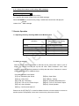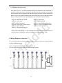
1
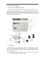
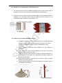
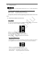
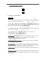
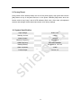
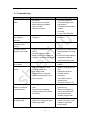
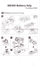
GSM Home Alarm System User Manual http://www.usmartbuy.com 1 1. Factory default Normally, all sensors in the big box have been coded (learnt) to the control host Operation Password: 0000 Long-Distance Control Enabled Programming Password: 8888 Call-In Ring Times 1 Siren Duration 300 Seconds Schedule Setting Disabled Wired Zone Disabled Delay Setting Disabled Power Output ON Zone Type Real-Time 2. Manipulation specification 2.1 Arming Arming means all-around guarded when there is no person at home. All detectors are working. Once something triggers any of the detectors, the alarm sets off. After arming operation, the ARM LED on the host will be blinking twice per second. Remote key fob operation: pressing arming key on the key fob. 2.2. At-home arming (Intelligent defense) Home arming means that when there is someone at home, for the sake of security, it is needed to make the outside doors, windows, balconies, and around detectors working. But, it is also needed to avoid the person at home from triggering the domestic detectors to alert wrongly. At this time, we choose home arming, letting some detectors work and the others not. After at-home arming operation, the ARM LED on the host will be blinking once per second. Remote key fob operation: pressing at-home arming key on the key fob. 2.3 Disarming Disarming means that when control host sets off, it can stop the alerting or makes the system on the disarmed status. After disarming, even triggering detectors can NOT make the control host alert, except the detectors in emergency zone or emergency key in the remote control. After disarming, ARM LED on the host dies out. Remote key fob operation: pressing disarm key on the key fob. 2.4 Emergency alerting When emergency happens, press the emergency key on the key fob. The siren will set off and the alarm will send SMS message or call to stored phone numbers. 2 3. Installation n and deb bugging 3 3.1 Control Host and SIM S Card In stallation he host in th he central zo one of the g uarding plac ce to We should try our bestt to install th s detectors ccan have th he best rece eiving effect.. Take care and makke sure thatt all wireless keep away from m large-scale metal objjects or hou usehold appliances withh high-freque ency interference. Att the same time, the hosst should be e away from m the steel-bbar concrete wall and anti-fire doo or, and othe er barriers. 3..2 Initialization A After installing the SIM card, conne ecting all wired sensors s (if applica ble), small siren s and antenna, tu urn on the ba ackup batterry switch at back of the host and thee power ada apter also o needs to be b connecte ed to the ho ost. Upon power p up, th he alarm paanel will carrry a self--test for few seconds. If GSM LED on the host h is blinki king once forr every 5 se econds, that means the host has found d the GSM signal s and iss ready to wo ork. 3 3.3 Indicating Information function Buzzer Defence Zone LED Arming LED Signal Interpretation Long “Beep” once Confirm prompt short “Beep” for 4 times Error prompt Always lit Defence zone alerting Defence zone is triggered when Blinking alarm is disarmed Blinking twice per second Arming status Blinking once per second Coming into At-home arming status Blinking once per second or always lit GSM LED Blinking once for every 5 seconds Not lit 3.4 1. 2. 3. 4. 5. 6. 7. 8. GSM signal weak, or SIM card not found GSM module, and SIM card working properly Without electricity Key fob Coding Press and hold [SET] for 3 seconds and release after a “Beep” and Arm LED flashes slowly Press the [SET] key again, all Defence zone LEDs lid, this is the configuration mode for remote control coding. Press any key on the key fob to trigger a wireless signal to the Panel. When control host receives signal and say “successfully added”, it means key fob has been added to panel successfully, this key fob can be used to control the alarm. If control host gives 4 short “Beep”, it means key fob has been learnt before. If control host says “error”, this means the wrong sensor were used to code You can take out all key fobs required to configure and trigger them one by one by repeating step (3) above. Pressing [SET] key again and again until all Defence zone LED off to exit the configuration status. Note: The control host allows up to 10 key fob to be coded. 4 3.5 1. 2. 3. Key Fob Decoding Press and hold [SET] for 3 seconds and release after a “Beep” and Arm LED flashes slowly Press the [SET] key again, all Defence zone LEDs lid, this is the configuration mode for remote control coding. Then press and hold the [SET] key for 3 seconds. Release after a long “Beep” and all Defence zone LED turn off means all key fobs are deleted. Note: All key fobs will be disconnected from the control host. 3.6 1. 2. 3. 4. 5. 6. 7. 8. 3.7 1. 2. 3. 4. Defence Zone Coding Press and hold [SET] for 3 seconds and release after a “Beep” and Arm LED flashes slowly Press the [SET] key again, all Defence zone LEDs lid, this is the configuration mode for remote control coding. Press [SET] key again, Defence Zone 1 LED on, this is the configuration mode of zone 1 ( You can press [SET] key again and again and the Defence Zone LED can switch from 1 to 6. So that you can choose to code sensor to different zones. Note: Each zone can learn 10 sensors. ) Trigger the detector When control host receives signal and say “successfully added”, it means the sensor has been added to host successfully. If control host gives 4 short “Beep”, it means the sensor has been learnt before. You can take out all sensors required to configure and trigger them one by one by repeating step (3) above. Pressing [SET] key again and again until all Defence zone LED off to exit the configuration status. Defence Zone Decoding Press and hold [SET] for 3 seconds and release after a “Beep” and Arm LED flashes slowly Press the [SET] key again, all Defence zone LEDs lid, this is the configuration mode for remote control coding. Press [SET] key again and again until the LED of Defence Zone that you want to delete the sensor from is ON. Then press and hold the [SET] key for 3 seconds, release after a long “Beep” and all Defence zone LED if off to indicate the successful operation. Note: All sensors will be disconnected from the selected zone. 5 3.8 Guideline for Installing Door or Window Sensor 1. The surface for door sensor installation should be clean so door sensor can be attached to the door and frame firmly with double faced adhesive tap. 2. Each door sensor consists of sensor part and magnet. The sensor part should be installed on the fixed door frame and the magnet should be placed on the movable door with a distance not exceeding 1 cm. 3.9 Guideline for Installing PIR Motion Sensor 1. Installation height is about 2.2 meters above ground and the optimized detection angle for most motion detector is 90 degree. The sensor should face the detected area with this consideration for best coverage. 2. Within coverage of detection, there should be no any objects for obstruction. 3. There should be no two infrared detectors in the same as they will possibly intervene with each other. 4. Avoid the detector facing window, cooling or warming machines, or other appliances that cause the temperature changing sharply and thus cause false alarm. 5. Most infra-red detector needs about 5 minutes to heat up before READY for normal operation. 6. Unless specifies otherwise, most infra-red detector are indoor use and not reliable to use outdoor. 6 4. Difference Between Password Types Operation password: This is used when you change the alarm status, e.g. arm or disarm Programming password: This is used when you configure or change the alarm setting, e.g. add a personal phone number 5. Voice Message Recording Make sure the alarm is in disarmed status, press [Set] for 3 times, the control host will say “record”, and recording starts: recording at 30cm away from the host. 10 seconds later and after one beep, recording stops. 6. Remote Programming ■ All programming for the alarm control host are completed through a phone call to the host and pressing on the calling phone keys or sending control SMS text message through a mobile phone to the host. 6.1 Call-In to Program On working status, use a phone to dial the SIM card phone number in the host. After control host picks up the call and say “input password”, enter the programming passwords (default is 8888). When each phone key is pressed, user can hear the voice to play the key number to confirm the entered key is accepted by the control host, otherwise please enter again. Once the password is entered correctly, the control host will enter long-distance programming status and then input the call-in command to program. 6.2 Sending SMS to Program Just send SMS text message command. Command format: Programming Password * or # Command parameter * or # 7 6.3 Change Password * 1 xxxx yyyy * Where “xxxx” is new 4-digit operation password and “yyyy” is 4-digit programming password. e.g. change operation password to 1234 and programming password to 8765: Call-in Command *112348765* (refer to section 6.1) SMS Command ProgrammingPassword*112348765* The operation password and the programming password cannot set to be the same. 6.4 Store Phone numbers into Control Host 6.4.1 Call Alert The control host will call store phone numbers when alarm is set off. The control host can store up to 6 phone numbers for call alert. # 1 ××…×× # # 2 ××…×× # # 3 ××…×× # # 4 ××…×× # # 5 ××…×× # # 6 ××…×× # Where “xx…xx” is the phone number. e.g. store 12345678 as first call alert phone number Call-in Command: #112345678# (refer to section 6.1) SMS command: ProgrammingPassword #112345678# 6.4.2 SMS Text Message Alert The control host will send SMS text message to store phone numbers when alarm is set off. The control host can store up to 3 mobile phone numbers for SMS alert. #7 #8 #9 ××…×× # ××…×× # ××…×× # Where “xx…xx” is the mobile phone number. e.g. store 12345678 as first SMS alert phone number Call-in command: #712345678# (refer to section 6.1) SMS command: ProgrammingPassword #712345678# 8 6.4.3 Delete stored Phone Numbers #1# #2# … #9# 6.5 Defence Zone Programming *8ABC* Where “A” is the defence zone number (For wireless zone, can be [1~6]). (For wired zone can be [7~0], where 0 stands for 10) “B” is the type of defence zone: [0]deleted zone; [1]real-time; [2]intelligent defense (home-armed) area; [3]emergency zone; [4]multi-checked defense area; [5] alarm delay (entry delay) defense area; [6] repeat triggered defense area “C” indicates if the siren sounds when sensor in select zone number A is triggered. [0] is siren-off and [1] is siren-on e.g. set the defence zone 1 to Emergency zone,siren is on for this zone Call-in command: *8131* (refer to section 6.1) Or SMS Command: ProgrammingPassword *8131* Emergency zone: No matter the alarm is armed or disarmed, the sensor in this zone will set off the alarm immediately, which is suitable for the gas, smoke, safe, emergency accesses and other special occasions. Intelligent (Home/Partial armed) zone: The sensor in this zone will not set off alarm when the alarm is Intelligent armed. Multi-checked zone: Under the situation of arming or intelligent arming, only if two or more detectors in multi-checked zone are triggered within 30 seconds, the alarm sets off. In this case, it can avoid false alarm caused by individual detector. Delay alarm zone: When a sensor in this zone is triggered, the alarm will delay to set off. Repeat triggered zone: When the detector is triggered once, the alarm will not go off immediately. Only when it is triggered again within 5-30 seconds after the first trigger, the alarm goes off. 9 6.6 Siren Options #0ABC# Where “A” can be 0 or 1. 0 is to turn on the siren prompt for arming and disarm when using the remote control (key fob). 1 is to turn off the prompt. “B”: can be 0 - 9 (minutes) and 0 is to turn off the siren. This is used to set the siren alarm length “C ": can be 0- 9 and 0 is to turn off the siren. This is used to set the siren sound volume. e.g. Siren prompts when arming/disarming by using key fob, siren sounds for five minutes and siren sound volume is 9 Call-in command:#0159# (refer to section 6.1) SMS Command: ProgrammingPassword #0159# 6.7 Power Output Setting *0AB* Where “A”: can be 0 – 9, it used to control the power output at back of the control host: 0= not turn on 12V output 1= turn on 12V output on disarming status, while close 12V output under other status. 2 or 3=turn on 12V output in arming status 4 or 5=turn on 12V output in home-armed status 6 or 7= turn on 12V output arming or home-armed status 8= turn on 12V output in when alarm is set off 9=always turn on 12V output “B”: can be 0 (means not sending SMS alert when the external power is cut) or 1 (means sending SMS alert when the external power is cut). 6.8 Clock Setting * 2 HH MM * “HH”: 2 digits of the present hour. “MM”: 2 digits of the present minute. e.g. set the time to 19:18 Call-in command: *21918* (refer to section 6.1) SMS Command: ProgrammingPassword *21918* 10 6.9 Schedule Setting 6.9.1 Scheduled Arming * 3 HH MM C * “HH”: the hour of the setting time “MM”: the minute of the setting time “C” : Can store 9 schedules. 1 - 5 are used to store daily repeat schedules and 6 - 9 are used to store one time schedules. 0 is to cancel all schedules e.g. Set to arm every day at 17:40 and store at the 1st schedule Call-in command: *317401* (refer to section 6.1) SMS Command: ProgrammingPassword *317401 6.9.2 Scheduled Disarming * 4 HH MM C * “HH”: the hour of the setting time “MM”: the minute of the setting time “C” : Can store 9 schedules. 1 - 5 are used to store daily repeat schedules and 6 - 9 are used to store one time schedules. 0 is to cancel all schedules e.g. Set to disarm on 8:00 once and store at the 9th schedule Call-in command: *408009* (refer to section 6.1) SMS Command: ProgrammingPassword *408009* 6.9.3 Scheduled Power Output * 5 HH MM C D * “HH”: the hour of the setting time “MM”: the minute of the setting time “C”: Can store 9 schedules. 1 - 5 are used to store daily repeat schedules and 6 - 9 are used to store one time schedules. 0 is to cancel all schedules “D”: 1 is to Turn on 12V power output,0 is to Turn off 12V power output e.g. Turn on 12V power output every day at 12:30 and store at the 5th schedule Call-in command: *5123051* (refer to section 6.1) Or SMS Command: ProgrammingPassword *5123051* e.g. Turn off 12V power output at 13:00 once and stored at the 9th schedule Call-in command: *5130050* (refer to section 6.1) Or SMS Command: ProgrammingPassword *5130050* 11 6.10 Call-in Ringing Times, Arm Delay (Exit Delay) & Alarm Delay (Entry Delay) Settings *6ABC* "A": can be 0 – 9. This is used to set the call-in ring times before host picks up the call. 0 means control host does not pick up the call "B": Arming delay time, can be 0 – 9 (10 seconds), 0 is to turn off the arming delay. Each value is equal to 10 seconds. "C": Alarm delay, can be 0 – 9 (10 seconds), 0 is to turn off the alarm delay. Each value is equal to 10 seconds e.g. Ring 9 times to answer, arming delay 50 seconds, alarm delay 10 seconds Call-in command: *6951* (refer to section 6.1) Or SMS Command: ProgrammingPassword *6951* 6.11 Set Up Wired Defense Area *7ABCD* A B C D refers to L1, L2, L3, L4 respectively. The value can be 1 or 0, 1 means wired normal open zone, 0 means wired normal close zone. Close wired zones:* 7 * 6.12 SMS Related Operation (For Advance User ONLY) 6.12.1 SMS alert message allocation *9AB* A: wireless zone number 1 ~ 6, wired zone number 7 ~ 0 (7, 8, 9, 0 is L1 ,L2, L3, L4 respectively) . B: SMS message series number and can be value 1 ~ 9 6.12.2 Set 9 groups of self-editing SMS messages Programming Password A SMS Content A is SMS series number, can be 1~9 e.g. set 9th SMS as “This is an alarm in emergency zone”. You can send SMS text message 88889This is an alarm in emergency zone to the control host by using a mobile phone. 12 6.12.3 Query the contents of self-editing SMS messages: Programming Password A * “A” is 1-9 (the SMS message serial number) e.g. querying the stored content for the 2nd SMS message: Send SMS 88882* to control host by using a mobile and control host will reply the stored nd content for 2 SMS message. 7. Remote Operation 7.1 Operating Alarm by Sending SMS from A Mobile Phone SMS Message Need to Send Operation (where default programming password is 8888) Arming ProgrammingPasswordSF Home-Arming ProgrammingPasswordBF Disarming ProgrammingPasswordCF Turn on 12V Power Output ProgrammingPasswordON Turn off 12V Power Output ProgrammingPasswordOFF 7.2 Call-in to control Dial the phone number associated to SIM card in the control host. After a cycle of ringing, the control host will pick up the call. After “Enter Password” voice, enter operation password (default password is 0000) and then after “Password is correct” voice, pressing phone or cellphone keys. Concrete operation is as follows: 【1】key: Monitoring the Scene 【3】key: Close Siren 【5】【#】key: Disarming 【7】Key: Turn on 12V Power Output 【9】Key: Open Speaker 【#】key: Confirm and Hand UP 【2】key: Open Siren 【4】【#】key: Arming 【6】Key: Playback Recorded Voice 【8】Key: Turn off 12V Power Output 【0】Key: Close Speaker Please note for【9】&【0】, is used for talkback function, the host needs to connect to another passive loudspeaker, which are 8 ohm and its power above 0.5W. 13 7.3 Telephone alert-receiving After alarm is set off, it will automatically dial pre-set telephones and cellphones in sequence. When user picks up the phone, the alarm will play recorded voice message and tell which zone is triggered and the following keys can be used to operate the alarm. If there is no person receiving call or the line is busy, the host will dial the next phone numbers until the alert call is picked up and confirmed by press【#】key. 【1】key: Monitoring the Scene 【3】key: Close Siren 【5】【#】key: Disarming 【7】Key: Turn on 12V Power Output 【9】Key: Open Speaker 【#】key: Confirm and Hand UP 【2】key: Open Siren 【4】【#】key: Arming 【6】Key: Playback Recorded Voice 【8】Key: Turn off 12V Power Output 【0】Key: Close Speaker Please note for【9】&【0】, is used for talkback function, the host needs to connect to another passive loudspeaker, which are 8 ohm and its power above 0.5W. 8. Wiring Diagram on the Host SP + & SP- are used to connect a passive speaker which is 8 ohm and its power above 0.5W, for talkback function. OUT is 12V programmable output drive current of 1A, 12V is a fixed output power, external electrical supply power. 14 9. Factory Reset Firstly switch off the backup battery and cut off the power supply, then press and hold the [Set] button on top of the panel and turn on the power. Release [Set] button when the buzzer emits a long “beep” and all LED indicators flash once. After reset, all registered sensors and settings will be cleared and return to its factory settings. 10. System Specification Input Voltage: DC9V~12V Standby Current: <55mA Alarm Current: <450mA Wireless Frequency: 433.92MHz GSM Frequency: 900/1800/1900MHz Backup Battery: NI-HI AAA*6 Alarm Loudness: 110dB Power Output DC12V 1A 15 DC7.4V 11. Troubleshooting Problem Probable Reasons Available Solutions 1. cannot dial for alarm do arming operation re-set according to the specification no arming alerting phone unsetted parts improperly installed code no match SIM card overdue coordinating the location of parts re-coding 5. pay to the SIM card 2. cannot long-distance operation password input wrongly ( or forgotten ) retry password or reset password 3. no record indication when alerting voice message not recorded record voice message 4. remote control (keyfob) out of order coding un-matched with the Panel re-learn the remote control change battery to correct type insufficient battery power battery pieces poor contact or contact the local dealer to change the matched voltage un-matched with Panel remote control (keyfob) 5. infrared detector out of order low power change to the same type battery 6. siren without sound siren plug or jack in short circuit or broken-line repair or change plug or jack siren out of order closed siren by command positive and ground wires of siren reversed change the jack line activate siren by command use another siren to double check reverse the wires to try 7. the transmission distance of detector to panel shorten 8. the signal LED blinking quickly a nearby emitter is sending code move one detector next to panel and try Panel receiver stoppage standby battery of the Panel insufficient identify the interfering source and eliminate it SIM card un-loaded SIM card is setting PIN code GSM signal weak 16 check Panel power whether plugged well reload SIM card cancel PIN code of SIM change to place with strong signal