1
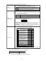
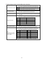
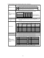
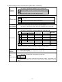
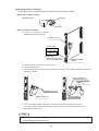
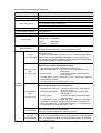
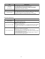
Ver.1.0
Produced in Jan. 1998
®
VME built-in controller
Model name
JW-32CV1
JW-32CV2
Instruction Manual
We thank you for your purchase of the SHARP built-in controller JW-32CV1/32CV2.
Carefully read this instruction manual so that having thoroughly familiarized yourself with the
functions and their operation method.
We are confident that these booklets will be helpful whenever you face problem.
Note
• This module is made in accordance with Japanese domestic specifications. Its
guarantee clauses are described in a separate guarantee card (packed together with the
module). When this module is used outside Japan, these guarantee clauses are not
applicable. In addition, the guarantee should be understood as a guarantee of the
delivered product as a single unit and every other damages or losses due to damage or
malfunction of the product will not be included in this guarantee.
• Should you have any questions and inquiries, please feel free to contact our dealers.
• The whole or partial photocopy of this booklet is prohibited.
• Contents of this booklet may be revised for improvement without notice.
Table of contents
Safety precautions .................................................................................................................................... 1
Chapter 1 Outline .................................................................................................................................... 3
Chapter 2 Precautions for use ................................................................................................................ 4
Chapter 3 System configuration .............................................................................................................. 5
3-1 System configuration ................................................................................................................. 5
3-2 System configuration using communication .............................................................................. 6
[1] Communication system using communication port ........................................................... 6
[2] Communication system using the satellite I/O link function ............................................... 7
[3] Communication system using the data link function .......................................................... 7
3-3 Cautions on system design ...................................................................................................... 10
Chapter 4 Name and function of each part ........................................................................................... 11
Chapter 5 Installation method ............................................................................................................... 12
Chapter 6 Wiring ................................................................................................................................... 13
6-1 Wire connections for the halt output and ground ..................................................................... 13
6-2 Wiring for satellite I/O link, data link (JW-32CV2) .................................................................. 14
[1] Wiring for satellite I/O link ................................................................................................ 14
[2] Wiring for data link ........................................................................................................... 14
6-3 Wiring for communication port ................................................................................................. 17
[1] Pin arrangement of PG/COMM1 port, PG/COMM2 port .................................................. 17
[2] Wiring figure ..................................................................................................................... 18
Chapter 7 How to use ........................................................................................................................... 19
7-1 Switch setting ......................................................................................................................... 19
[1] Switch setting of JW-32CV1 ............................................................................................ 19
[2] Switch setting of JW-32CV2 ............................................................................................ 20
7-2 Memory map ............................................................................................................................ 29
[1] Relationship between this module’s memory and the VME master memory ................... 29
[2] PC section memory ......................................................................................................... 30
7-3 Access method of dual port RAM ............................................................................................ 31
[1] Data transfer using a ladder program indirect assignment instruction ............................. 31
[2] Data transfer by area assignment .................................................................................... 33
7-4 Operation check of the VME master and the JW-32CV1/32CV2 ............................................ 35
[1] To use this module to check the VME master operation. ................................................ 35
[2] To check the operation of the module with the VME master ........................................... 35
7-5 Allocation of I/O address .......................................................................................................... 36
Chapter 8 Troubleshooting and maintenance ....................................................................................... 38
[1] Troubleshooting ............................................................................................................... 38
[2] Self-diagnostic function .................................................................................................... 38
[3] Exchange method of batteries ......................................................................................... 39
Chapter 9 Specifications ....................................................................................................................... 40
[1] General specifications ..................................................................................................... 40
[2] PC section performance specifications ............................................................................ 41
[3] Interface specifications .................................................................................................... 42
Safety precautions
Read this manual and attached documents carefully before installation, operation, maintenance and
checking in order to use the machine correctly. Understand all of the machine knowledge, safety
information, and cautions before starting to use. In this instruction manual, safety precautions are ranked
into “danger” and “caution” as follows.
Danger
: Wrong handling may possibly lead to death or heavy injury.
Caution
: Wrong handling may possibly lead to medium or light injury.
Even in the case of
Caution , a serious result may be experienced depending on
the circumstances. Anyway, important points are mentioned. Be sure to observe them
strictly.
The picture signs of prohibit and compel are explained below.
: It means don’ts. For example, prohibition of disassembly is indicated as (
: It means a must. For example, obligation of grounding is indicated as (
).
).
1) Installation
Caution
• Use in the environments specified in the catalog and instruction manual.
Electric shock, fire or malfunction may be caused when used in the environments of high
temperature, high humidity, dusty or corrosive atmosphere, vibration or impact.
• Install according to the manual.
Wrong installation may cause drop, trouble or malfunction.
• Never admit wire chips or foreign matter.
Or fire, trouble or malfunction may be caused.
2) Wiring
Compel
• Be sure to ground.
Unless grounded, electric shock or malfunction may be caused.
Caution
• Connect the rated power source.
Connection of a wrong power source may cause a fire.
• Wiring should be done by qualified electrician.
Wrong wiring may lead to fire, trouble or electric shock.
–1–
3) Use
Danger
• Don’t touch the terminal while the power is being supplied or you may have on electric shock.
• Assemble the emergency stop circuit and interlock circuit outside of the JW-32CV1/32CV2.
Otherwise breakdown or accident damage of the machine may be caused by the trouble of
the JW-32CV1/32CV2.
Caution
• “Run” or “stop” during operation should be done with particular care by confirming safety.
Misoperation may lead to damage or accident of the machine.
• Turn ON the power source in the specified sequence. Turn ON with wrong sequence may
lead to machine breakdown or accident.
4) Maintenance
Danger
• Never connect battery in wrong polarity, or charge, disassemble, heat, throw into fire, or
short-circuit. Or it may be broken or ignited.
• Do not subject the battery to impact of any kind. Do not pull on the lead wires of the battery,
or liquid leakage accident may occur.
Prohibit
• Don’t disassemble or modify the modules.
Or fire, breakdown or malfunction may be caused.
Caution
• Turn OFF the power source of VME rack panel before detaching or attaching the JW-32CV1/
32CV2. Or electric shock, malfunction or breakdown may be caused.
–2–
Chapter 1 Outline
The JW-32CV1/32CV2 VME built-in controller (hereafter referred to as “the module”) can be connected
directly to the VME bus by installing it in a VME slot. This is a high performance programmable controller
(hereafter referred to as a “PC”). It can easily create a data interface to a VME master through its dual port
RAM.
Its PC section is based on a CPU core which is equivalent to Sharp’s JW30H series PC control module JW32CUH1, and offers super high speed PC operation.
With variety of interfaces equivalent to the JW30H series PC (I/O bus, communication port, I/O link, and
data link), it can easily be integrated into a system together with other PCs, LCD control terminals, and host
computers.
[JW-32CV1/32CV2 function]
Contents
Item
JW-32CV1
JW-32CV2
Maximum number of input/output points 1024 points
Program capacity
Data
memory
31.5 K words
Register*
25 K bytes
File memory
32 K bytes (file 2)
Clock function
Standard
Communication port data transfer rate
115200/57600/38400/19200/9600/4800/2400/
1200 bits/s
Basic instruction: 0.038μs
Transfer instructions (F-00): 1.22μs
Instruction processing speed
Number of modules on a single
expansion rack panel
3 modules maximum
Total I/O expansion cable distance
14 m maximum
Satellite I/O link
(functionally equivalent to the JW-23LMH)
Data link
(functionally equivalent to the JW-21CM)
None
Yes
*The general registers include a register (16K bytes) for file 1 which can use application
instructions to directly assign addresses.
· The JW-32CV2 has both a satellite I/O link function and a data link function. However, the JW32CV1 does not have these functions.
[Other reference manuals]
This manual describes the installation method, wiring method, switch settings, memory map, and
specifications of the module. For details about its use and other settings, see the instruction manuals
listed below.
· PC functions ⇒ See the description for the JW-32CUH1 functions (program capacity: 31.5 K
words, file 2 capacity: 32 K bytes) in the “JW30H user’s manual - hardware
version” and the “JW30H programming manual - ladder instruction version.”
· Satellite I/O link functions ⇒ See the description for the JW-23LMH functions in the “JW-23LMH
user’s manual.”
· Data link functions (remote I/O, DL1 data link, DL9 data link, computer link)
⇒ See the description for the JW-21CM in the “JW-21CM user’s manual.”
· Data link functions (M net communication) ⇒ See the “M net user’s manual.”
–3–
Chapter 2 Precautions for use
Pay attention to the following items when installing or using the module.
(1) Handling
· Do not install or store the module in places that are subject to direct sunlight, rapid temperature
variation, high humidity, dust, strong magnetic fields, vibration, or strong shocks.
· In order to protect the LSIs and ICs inside the module from damage by static electricity, cover
the modules with anti-static conductive sheets to transport or store them.
· Make sure to turn OFF the power, before changing the jumper shunts on the module.
· If you set up a separate power supply for the module, make sure the power it supplies has a low
output impedance with very low ripple and noise characteristics.
(2) Installation and removal of the module
· Make sure to turn OFF the power before installing or removing the module.
· If you install the module on a VME bus (install the module in the 2nd or lower slots of the VME
bus back plane), make sure to remove the respective jumper shunt on the VME bus back
plane.
1. Check the setting of the jumpers on the module.
2. Turn OFF the VME system power, and remove all the jumper shunts on the respective VME
back plane position where the module is installed.
3. Connect all necessary connectors before turning ON the power.
4. Turn ON the power to the system and check the operation of each module.
Jumper shunt
VME rack connector
· To install or remove the module in a VME rack, push it straight in or pull it straight out in order
not to make contact with other modules in the adjacent slots. (See page 12)
· If the module does not function after installation, the jumper shunt for the module on the VME
back plane may not have been removed (or some other jumper shunt was removed), or the
module may not be set appropriately. Be careful. If the module is not set appropriately, it may
malfunction.
· Make sure to disconnect both the module halt output signal lines before removing the module
from the slot. If you want to remove another module next to this module, you should also
disconnect the power to the halt output signal of the module. (See page 12)
–4–
Chapter 3
System configuration
3-1 System configuration
I/O module, special I/O module
Expansion rack panel
(No. of connected modules: 3 sets max.)
JW-32CV1/32CV2
RUN FAULT
PG/COMM1
PG/COMM2
I/O expansion cable
Cable total length
: 14m max.
Betweem rack panels
: 10m max.
Rack 3
Rack 2
Rack 1
PG connection cable
JW-32CV1
JW-32CV2
I/O
・Allocation of I/O address
⇒ See page 36.
Support tool
Personal computer (IBM-PC)
Programmer
Multi-purpose
programmer
Ladder software
3 modules maximum (3 racks maximum)
Number of modules on
· The module can be connected to JW-34ZB/36ZB/38ZB expansion
a single expansion rack
rack panel for the JW20H/30H. (An I/O bus extension adapter
panel (maximum number
cannot be used.)
of racks)
Number of input/output
and special I/O modules
Total cable extension
length
A total of 24 modules can be installed on racks 1 through 3.
· I/O modules and special I/O modules for the JW20H/30H can be
installed, but the option module cannot be used.
14 m maximum (10 m maximum between any two basic rack panels)
· A JW-203EC/207EC/22EC/25EC/210EC I/O expansion cable for the
JW20H/30H can be used to connect rack panels.
–5–
3-2 System configuration using communication
[1] Communication system using communication port
By using a communication port of the module, the JW-32CV1/32CV2 can communicate with a host
computer such as a personal computer and a LCD control terminal.
JW-32CV1/32CV2 have 2 ports (PG/COMM1,PG/COMM2) for communication port.
JW-32CV1/32CV2
Host computer
RUN FAULT
PG/COMM1 port
PG/COMM1
RS-422A only
(Usable when the support tool
PG/COMM2
is not connected.)
Host computer
PG/COMM2 port
RS-232C or RS-422A
(Usable when the support tool
is not connected.)
I/O
Specifications
Item
RS-232C connection
Number of connected modules
of JW-32CV1/32CV2
Communication cable
RS-422A connection
1 sets (1: 1 connection)
31 sets max. (1: N connection)
*1
Shielded cable
15 m max.
Shielded twisted pair cable
Cable total length: 1 km max.
4-wire system
*2
(Party line connection)
Transfer speed
115200/57600/38400/19200/9600/4800/2400/1200 bits/s
Data formats
Start bit
Data length
Parity bit
Stop bit
Used characters
ASCII alphanumerical characters
: 1 bits
: 7 bits
: 1 bit (odd/even/none)
: 1/2 bits
*1 To obtain data transfer speeds higher than 38400 bit/s, the JW-32CV1 must be
connected directly to a host computer.
*2 Two-wire system communications are not possible.
The use of the communication port, such as for setting system memory, is the same as for the JW32CHU1.
⇒ See “JW30H user’s manual hardware version.”
–6–
[2] Communication system using the satellite I/O link function
The system can communicate between a JW-32CV2 as an I/O link master station and an I/O link
slave station.
JW-32CV2 (master station)
RUN FAULT
PG/COMM1
PG/COMM2
(Slave station)
8-point module
(Slave station)
16-point module
(Slave station)
32-point module
(Slave station)
LCD control terminal,
manifold solenoid valve, etc.
I/O
Shielded twisted pair cable
Total maximum
172.8 k bits/s
32 slave stations max.
extension length: 1km 345.6 k bits/s ※Note
Note: The communication speed of 345.6 k bits can be achieved only when in communication
with high speed type slave module as follows:
Specifications
Item
8-point module
16-point module
: ZW-82N (input), ZW-82S (output)
: ZW-161N/162N (input), ZW-161S/162S/164S
(output), ZW-162M (I/O)
16-point module : ZW-164NH (input), ZW-162SH (output),
(high speed type) ZW-162MH (I/O)
Model name of slave 32-point module : ZW-324NH (input), ZW-322SH (output),
(high speed type) ZW-322MH (I/O)
station
8-point module (sensor connector system, high speed type)
: ZW-84NC (input)
16-point module (sensor connector system, high speed type)
: ZW-162MC (I/O)
LCD control terminal: Z-SM10
No. of slave station connected 32 sets max.
504 points max.
No. of I/O link points
[3] Communication system using the data link function
By toggling switch SW10, you can set the JW-32CV2 to function as a remote I/O master station, a
DL1 data link (N: M system), a DL9 data link (1: N system), a computer link, or a M net communication
device. With this selection, you can use any one communication system and the satellite I/O link
function [2].
(1) Remote I/O master station
The system can communicate between a JW-32CV2 as remote I/O master station and a JW series
module as remote I/O slave station.
JW-32CV2 (master station)
JW-21RS
(slave station)
RUN FAULT
PG/COMM1
PG/COMM2
JW-21RS
(slave station)
JW-21RS
(slave station)
JW-21RS
(slave station)
I/O
Shielded twisted pair cable
Total maximum
307.2 k bits/s
extension length: 500m
Specifications
Item
Model name of slave station (PC)
No. of slave stations connected
No. of remote I/O points
No. of I/O points per station
No. of special I/O modules mounted
on a JW-21RS
4 slave station max.
JW-21RS (JW20H, JW30H)
4 sets max.
Total points: 512 (64 bytes)
128 points (16 bytes)
8 max. (total of 4 slave stations)
–7–
(2) DL1 data link
The system communicates between the JW30H and JW series PC through the JW-32CV2 as a
master or a slave station.
This link offers communication between a master and a slave station, or between 2 slave stations.
(N: M method). JW-32CV2
JW-32CV2
(slave station)
(master station)
RUN FAULT
JW-21CM
(slave station)
RUN FAULT
PG/COMM1
PG/COMM1
PG/COMM2
PG/COMM2
I/O
I/O
JW30H
Shielded twisted pair cable
Total maximum
extension length: 1km
Item
JW-10CM
(slave station)
JW70H
153.6 k bits/s
15 slave
stations max.
Specifications
Model name of
master/slave station (PC)
No. of modules
connected
No. of link bytes
No. of link bytes
per station
JW-32CV2
JW-21CM (JW20H, JW30H)
JW-10CM (W70H/100H, JW50H/70H/100H)
Z-331J/332J (J-board)
16 sets max. (including master station)
Total 64 bytes (512 points)
· Divided equally according to the number of slave stations when a JW-32CV2,
JW-21CM, or a Z-331J/332J is used as master station. (1 station: 32 bytes, 2
or 3 stations: 16 bytes each, 4 to 7 stations: 8 bytes each, and 8 to 15 stations:
4 bytes each.)
· When master station is other than JW-32CV2, JW-21CM, or Z-331J/332J, total
of max. 64 bytes will be allocated.
(3) DL9 data link
The system communicates between the JW30H and JW series PC through the JW-32CV2 as a
master or a slave station.
This link offers communication between a master and a slave station. It cannot perform
communication between 2 slave stations (1: N method).
JW-32CV2
(slave station)
JW-32CV2
(master station)
RUN FAULT
JW-21CM
(slave station)
RUN FAULT
PG/COMM1
PG/COMM1
PG/COMM2
PG/COMM2
I/O
I/O
Shielded twisted pair cable
JW30H
Total maximum
extension length: 1km
Item
Model name of
master/slave station (PC)
No. of slave stations connected
No. of link bytes
No. of link bytes
per station
JW-10CM
(slave station)
JW70H
153.6 k bits/s
15 slave
stations max.
Specifications
JW-32CV2
JW-21CM (JW20H, JW30H)
JW-10CM (W70H/100H, JW50H/70H/100H)
Z-331J/332J (J-board)
15 sets max.
· Select from 512/256/128/64 bytes when a master station is a JW-32CV2, JW21CM, or Z-331J/332J.
· When master station is other than JW-21CM, or Z-331J/332J, total of max. 512
bytes will be allocated.
· Divided equally according to the number of slave stations when a JW-32CV2,
JW-21CM or a Z-331J/332J is used as master station. (1or 2 stations: 128
bytes, 3 or 4 stations: 64 bytes each, 5 to 8 stations: 32 bytes each, and 9 to 16
stations: 16 bytes each.)
· When master station is other than JW-32CV2, JW-21CM, or Z-331J/332J, total
of max. 127 bytes will be allocated.
–8–
(4) Computer link
The link offers communication between a host computer as a master station and a JW-32CV2 as a
JW-10CM
slave station.
JW-32CV2
(slave station)
Host computer
JW-21CM
(slave station)
RUN FAULT
PG/COMM1
JW30H
PG/COMM2
(slave station)
JW70H
I/O
RS-232C/422 converter
RS-485
RS-232C
31 slave stations max.
Z-101HE
Item
Specifications
Model name of
slave stations (PC)
JW-32CV2, JW-21CM (JW20H, JW30H), Z-331J/332J (J-board),
JW-10CM (W70H/100H, JW50H/70H/100H)
No. of slave stations connected
31 sets max. (1: N connection)
Communication
cable
A shielded twisted pair cable. Cable total length: 1 km. 2-wire system.
Transfer speed
19200/9600/4800/2400/1200/600/300 bits/s
Data formats
Start bit
Data length
Parity bit
Stop bit
Used characters
ASCII alphanumeric characters
: 1 bit
: 7 bits
: 1 bit (odd/even)
: 2 bits
(5) M net communication
With M net communication, automatic control facility equipment for production (such as a PC or
robot controller) controls the data sent and received between a master station and slave station.
This system cannot be used to communicate directly between slave stations.
RUN FAULT
PG/COMM1
PG/COMM2
JW-32CV2
(matser station)
JW-32CV2
(slave station)
I/O
JW-21CM
(slave station)
RUN FAULT
PG/COMM1
PG/COMM2
JW30H
M-net
specification
device
I/O
7 slave stations max.
Specifications
Item
Master station and slave
stations
Equipment M net specifications
(When using Sharp PC series controllers)
· Models which can be used as master and slave stations
JW-32CV2, JW-21CM (JW20H, JW30H)
JW-10CM (W70H/100H, JW50H/70H/100H), Z-331J/332J (J-board)
· Models which can be used as slave stations.
ZW-82N/82S, ZW-161N/162N/161S/162S/164S/162M, ZW-84NC/162MC
ZW-164NH/162SH/162MH, ZW-324NH/322SH/322MH
Number of stations that can
be connected
Number of linke points
connectable
8 stations maximum
Same as on the left
(1 master and 7 slave stations)
512 points maximum
(a total of 64 bytes for sending and receiving) 256 points maximum (32 bytes)
Transfer speed
19.2 k bits/s, 38.4 k bits/s
Data transfer specifications
Equivalent to M net specifications
Communication cable
Cable total length 1 km maximum
Cable total length 100 m maximum
Communication method
Half-duplex system
Same as on the left
Sharp PC specifications
(master station)
19.2 k bits/s
Standard M net system
specifications (reference)
· M net is a system equivalent to an “interface standard between stations” for creating a data link
between a PC and other devices.
–9–
3-3 Cautions on system design
A principle difference between a programmable controller (PC) and a conventional relay circuit is that a
PC controls each operation cyclically (in series), whereas relay circuit controls it in parallel.
Therefore, relay circuits limit the effect of an abnormal operation to a block.
However, a PC allows abnormal operations of the whole system when an abnormal condition occur.
In order to create a fail-safe system, we recommend preparing independent external protective circuits for
following functions, which may cause a breakdown of machine or injury to workers:
• Emergency stop circuit,
• Protection circuit,
• Operating circuit of high voltage device.
Also, be aware of the operation response time, as a PC operates using cyclic processing.
To prevent mis-operation due to output signal of the output module soon after switching on power to the
JW-32CV1/32CV2, connect in series the halt output for the JW-32CV1/32CV2 in the following operation
stand-by circuit.
· Connecting the input module and output
module for lighting lamps in front of emergency stop circuit makes it possible to grasp
the stop condition of devices.
JW-32CV1/32CV2
Input module
· When the JW-32CV1/32CV2 stops its operation, all the output module indicate ON/OFF
condition just before stopping.
Note: When setting an output holding address in the system memory, all the
output after the setting address is retained and you can reset the previously set address. (only available
when power is supplied to the JW32CV1/32CV2.)
Output module
Emergency
stop
Operation
preparation
JW-32CV1
JW-32CV2
Halt output
· Halt output
An output which opens when the CPU has
an error (internal watch dog timer times out)
or is halted.
MC
Thermal
MC
Output module
Relay output (normally closed, opens on
error/halt)
Maximum load: 1 A/30 VDC, 250 VAC
MS1
MS2
MS2
MS1
· Interlock circuit
Prepare external interlock circuit to prevent
reverse operation, damage of machines and
injury of workers.
Note: When DC output module is used as a
output module, use AC relay and install its contact in the emergency stop
circuit.
–10–
Chapter 4
Name and function of each part
(Front view)
①
⑩
JW-32CV2
②
(Side view)
⑨
RUN FAULT
PG/COMM1
③
SW12
④
SW13
PG/COMM2
⑤
HALT
OUTPUT
HALT
OUTPUT
100-240VAC
100-240VAC
24VDC
24VDC
+
LM-L2
SW3
SW2
CM-L1
CM-L2
SHLD
FG
FG
SW5
FG
SW4
SW1
LM-L1
⑥
(JW-32CV2)
(JW-32CV1)
⑦
I/O
SW6
Version label
SW16 SW17
SW15
⑧
SW10 SW11 SW9 SW8 SW7
⑪
⑩
⑨
• SW1 to 13, SW15 to 17 are switches. (JW-32CV1 uses SW1/12/13/15 only.)
For setting contents of switch, see “7-1 Switch setting.”
Function
Name
①
Model name label
②
RUN lamp (green)
③
FAULT lamp (red)
JW-32CV1 or JW-32CV2
· Lights when the module is operating normally.
· Programming after connecting support tool: Blinking, (PC stops operation)
· Detect errors by self-diagnosis function: Lights OFF.
(when battery is error, lights ON.)
Lights when detecting errors by self-diagnosis. PC stops its operations.
(However, it operates even when battery is error.)
· Connecting with support tool.
· Connecting with device having serial I/O port such as personal computer.
(RS-422)
· Connecting with device having serial I/O port such as personal computer.
(RS-422/RS-232C) (Also possible to connect with support tool.)
④
PG/COMM1 port
⑤
PG/COMM2 port
⑥
⑦
Terminal block
Connecting extended line of halt output, FG, I/O link, and data link.
I/O expansion connector Install an I/O expansion cable, and connect it with this connector.
⑧
Battery label
Indicates the battery is low, and shows the time left to change the battery
without data loss. (See page 39)
⑨
Module retention screw
Install the module on the VME rack.
⑩
Ejector handle
Used to remove the module from the VME rack.
⑪
Battery
Backup battery for the module.
–11–
Chapter 5 Installation method
This chapter describes how to install or remove the module on a VME rack.
Make sure to turn OFF the power to the VME rack before installing or removing the module.
[Installation procedure]
① Insert the module into a slot (connector) on the VME rack.
· Insert it straight into the VME module while being careful that the connector marked with an asterisk
* in the figure below does not touch an adjacent module.
② Secure the module in the VME rack using the two module screws.
Installation hole of
VME rack
Module retention
screw (②,③) Ejector handle (④)
VME rack
side connector
*
Ejector handle (④)
Module retention
screw (②,③)
Installation hole of VME rack
[Removal procedure]
Before removing the module, make sure to disconnect the power lines to both terminals for the module’s
halt output signal.
③ Remove the two screws securing the module in the VME rack.
④ Pull the module out from the VME rack using the two ejection handles.
· Pull the module straight out while being careful not to allow the connector marked with an asterisk
* in the figure above to touch an adjacent module.
For precautions about working around the VME rack, see “Chapter 2 Precautions for use” in this manual.
–12–
Chapter 6
Wiring
6-1 Wire connections for the halt output and ground
(1) In case of JW-32CV1
(Front view)
①
⑩
JW-32CV2
②
(Side view)
⑨
RUN FAULT
PG/COMM1
③
SW12
④
SW13
PG/COMM2
⑤
HALT
OUTPUT
HALT
OUTPUT
100-240VAC
100-240VAC
24VDC
24VDC
+
SW4
SW1
LM-L1
⑥
LM-L2
CM-L1
CM-L2
FG
SHLD
FG
FG
SW3
SW2 SW5
(JW-32CV2)
(JW-32CV1)
⑦
I/O
SW6
SW16 SW17
SW15
Version label
⑧
SW10 SW11 SW9
SW8
SW7
⑪
⑩
⑨
(2) In case of JW-32CV2
JW-32CV2
RUN FAULT
PG/COMM1
PG/COMM2
HALT
OUTPUT
100-240VAC
24VDC
HALT
OUTPUT
100-240VAC
24VDC
LM-L1
LM-L1
LM-L2
LM-L2
CM-L1
CM-L1
Halt output
}
· Be sure to connect the line to the emergency stop circuit.
· The halt output does not have a built in protection circuit.
You must provide a protection externally with a fuse or
similar device.
CM-L2
SHLD
CM-L2
FG
SHLD
This SHLD (shield) terminal and FG (frame ground) terminal
are conductive inside.
FG
I/O
Ground line
· To prevent noise error, be sure to separately prepare class-3
ground.
–13–
6-2
Wiring for satellite I/O link, data link (JW-32CV2)
Shown below is a method for hooking up a JW-32CV2 using the satellite I/O link function and the data
link function.
[1] Wiring for satellite I/O link
Connect to a two-wire system.
[Example]
Slave station 03(8)
(ZW-161N)
L1
L2
SG
SHIELD
FG
Class-3 grounding
Class-3
grounding
∼
∼∼
∼∼
∼∼
∼
Slave station 01(8)
(ZW-161N)
L1
L2
SG
SHIELD
FG
Master station
(JW-32CV2)
LM-L1
LM-L2
CM-L1
CM-L2
SHLD
FG
Slave station 37(8)
(ZW-161S)
L1
L2
SG
SHIELD
FG
Class-3 grounding
Class-3 grounding
Shielded twisted pair cable
Cable total length: 1km or less
(No. of slave stations: 32 sets max.)
Slave station 01(8)
(ZW-324NH)
Slave station 03(8)
(ZW-322SH)
L1
L2
SHIELD
FG
L1
L2
SHIELD
FG
Class-3 grounding
∼
∼∼
∼∼
∼∼
∼
Master station
(JW-32CV2)
LM-L1
LM-L2
CM-L1
CM-L2
SHLD
FG
Class-3 grounding
Slave station 37(8)
(ZW-322MH)
L1
L2
SHIELD
FG
Class-3 grounding
Shielded twisted pair cable
Class-3
grounding
Cable total length: 1km or less
(No. of slave stations: 32 sets max.)
[2] Wiring for data link
(1) When using remote I/O function
Mater station
(JW-32CV2)
LM-L1
LM-L2
CM-L1
CM-L2
SHLD
FG
Shielded twisted pair cable
Slave station 01(8)
(JW-21RS)
L1
L2
SHIELD
FG
Class-3
grounding
Slave station 02(8)
(JW-21RS)
L1
L2
SHIELD
FG
Slave station 03(8)
(JW-21RS)
L1
L2
SHIELD
FG
Class-3 grounding Class-3 grounding
Cable total length: 500m or less
(No. of slave stations: 4 sets max.)
–14–
Slave station 04(8)
(JW-21RS)
L1
L2
SHIELD
FG
Class-3 grounding
Class-3 grounding
(2) When using DL1 data link function
Mater station
Slave station 01(8)
(JW-32CV2)
(JW-32CV2)
LM-L1
LM-L2
CM-L1
CM-L2
SHLD
FG
Class-3
grounding
∼
∼
∼∼ ∼
∼∼
∼
LM-L1
LM-L2
CM-L1
CM-L2
SHLD
FG
Shielded twisted pair cable
Slave station 02(8)
Slave station 17(8)
(JW-10CM)
(JW-21CM)
L1
L2
SHIELD
GND
L1
L2
SHIELD
FG
Class-3 grounding Class-3 grounding
Class-3 grounding
Cable total length: 1km or less
(No. of slave stations: 15 sets max.)
(3) When using DL9 data link function
Slave station 01(8)
(JW-32CV2)
LM-L1
LM-L2
CM-L1
CM-L2
SHLD
FG
Class-3
grounding
Shielded twisted pair cable
Slave station 02(8)
(JW-21CM)
L1
L2
SHIELD
FG
1
2
Receiving data
3
Sending request
4
Signal grounding
7
Sending data
Cable total length: 1km or less
(No. of slave stations: 15 sets max.)
LM-L1
LM-L2
CM-L1
CM-L2
SHLD
FG
Z-101HE
FG
TD
RD
RS
SG
RD(+)
RD(-)
SHIELD
Class-3
grounding
15m or less
RS-232C
Class-3 grounding
Shielded twisted pair cable
Slave station 02(8)
Slave station 37(8)
(JW-21CM)
(JW-10CM)
L1
L1
L2
L2
SHIELD
SHIELD
GND
FG
∼
∼∼
∼∼
∼∼ ∼
FG
TD
RD
RS
SG
Outside body
grounding
Slave station 17(8)
(JW-10CM)
L1
L2
SHIELD
GND
Class-3 grounding Class-3 grounding
(4) When using computer link function
Connect to a two-wire system.
Slave station 01(8)
(JW-32CV2)
RS-232C/422 converter
Host computer
∼
∼∼
∼∼
∼∼
∼
Master station
(JW-32CV2)
LM-L1
LM-L2
CM-L1
CM-L2
SHLD
FG
Class-3 grounding Class-3 grounding
Class-3 grounding
Cable total length: 1km or less
RS-485 (No. of slave stations: 31 sets max.)
(5) When using M net communication function
Connect to a two-wire system.
Shown below is an example using Sharp PC devices for all master and slave stations.
Slave station 01(8)
(JW-32CV2)
LM-L1
LM-L2
CM-L1
CM-L2
SHLD
FG
Class-3
grounding
Shielded twisted pair cable
Slave station 02(8)
(JW-21CM)
L1
L2
SHIELD
FG
∼
∼∼
∼∼
∼∼
∼
Master station
(JW-32CV2)
LM-L1
LM-L2
CM-L1
CM-L2
SHLD
FG
Class-3
Class-3
grounding
grounding
Cable total length: 1km or less
(No. of slave stations: 7 sets max.)
–15–
Slave station 07(8)
(JW-10CM)
L1
L2
SHIELD
GND
Class-3
grounding
Note
· Connect the shield line of the cable with SHIELD terminal of master/slave station.
· Be sure to execute class-3 groundin FG terminal of the master station JW-32CV2 and slave station
via the basic rack panel. Avoid co-grounding with other modules. If not grounded, modules easily
pick up electric noise, which causes a malfunction.
· Do not execute multiple-wiring from one source point for communication cable.
Good
No good
Connected using
a connector
Conjunction terminal
· Keep the communication cable as far away as possible from the high voltage and power lines, so as not
to close in parallel.
· Use our recommended cable for communication cable and keep its total length within provisional length.
· Not necessary to set the master station JW-32CV2 and the slave station in order, one by one nor setting
the master station as terminal station. The following example is available.
Slave station 4 Slave station 1 Slave station 2 Master station Slave station 3
Turn ON termination resistance switch for terminal station
· Do not wire load driving cabels and power supply in the same duct of communication cable. (For the
cable supplying power to a slave station exclusively and not for load driving, wiring in the same duct is
available.)
Communication cable
Slave station
Mater
Wiring for DC
station
power supply Power cable pipe
DC power
supply
–16–
6-3 Wiring for communication port
Shown below is a method for connecting the module communication port (PG/COMM1, PG/COMM2)
to equipment with an RS-232C/RS-422A I/O port, such as a host computer.
[1] Pin arrangement of PG/COMM1 port, PG/COMM2 port
PG/COMM1 port
8
7
6
5
4
3
2
1
9 10 11 12 13 14 15
Pin No.
(15 pin D-sub
female connector)
JW-32CV1/32CV2
RUN FAULT
PG/COMM1
1
2
3
4
5
6
7
8
9
10
11
12
13
14
15
Signal
name
FG
Contents
Signal
Outside body grounding
*
SD (+) Sending data (PC to personal computer) RS-422A
*
RS-422A
RTS (–)
Signal grounding
SG
Signal grounding
SG
*
RD (+) Receiving data (personal computer to PC)
RD (–) Receiving data (personal computer to PC) RS-422A
SD (–) Sending data (PC to personal computer)
RS-422A
RTS (+) *
+5V
+5V
* Not connected with pin No. 2, 4, 8, and 12.
PG/COMM2
PG/COMM2 port
8
7
6
5
4
3
2
1
I/O
9 10 11 12 13 14 15
Pin No.
(15 pin D-sub
female connector)
1
2
3
4
5
6
7
8
9
10
11
12
13
14
15
Signal
name
FG
SD
SD (+)
RD
RTS (–)
SG
SG
RTS
RD (+)
RD (–)
SD (–)
CTS
RTS (+)
+5V
+5V
–17–
Contents
Signal
Outside body grounding
Sending data (PC to personal computer) RS-232C
Sending data (PC to personal computer) RS-422A
Receiving data (personal computer to PC) RS-232C
RS-422A
Signal grounding
Signal grounding
ON while PC is supplied power source RS-232C
Receiving data (personal computer to PC)
Receiving data (personal computer to PC) RS-422A
Sending data (PC to personal computer)
ON : Available sending, OFF : Ban sending RS-232C
RS-422A
[2] Wiring figure
(1) When using RS-232C for communication method of host computer side
Be within 15m for the total length of a communication cable.
JW-32CV1/32CV2
(PG/COMM2 port)
Pin No. Signal
name
FG
1
Shielded wire
Host computer
Signal
name
FG
2
SD
RD
4
RD
TD
8
RTS
CS
12
CTS
RS
7
SG
SG
15m or less
RS-232C
Use the RS-232C/RS-422 converter, such as Z-101HE, when the total length of the communication
cable is over 15m.
JW-32CV1/32CV2
RS-232C/RS-422 converter
PG/COMM1 port
(Z-101HE)
or PG/COMM2 port
Host computer
Signal
Signal
Signal
Terminal
Pin No. name
block name Pin No. name
name
RD
3
3
SD (+)
RD (+)
RD
11
SD (-)
RD (-)
2
TD
TD
9
RD (+)
TD (+)
4
RS
RS
10
RD (-)
TD (-)
7
SG
SG
1
FG
SHIELD
1
FG
FG
Shielded
wire
Shielded
wire
Class-3 grounding
1km or less
RS-422A
15m or less
RS-232C
(2) When using RS-422A for communication method
Be within 1km for the total length of a communication cable.
JW-32CV1/32CV2
PG/COMM1 port
or PG/COMM2 port
JW-32CV1/32CV2
PG/COMM1 port
or PG/COMM2 port
Host computer
Pin No. Signal
name
Pin No. Signal
name
Signal
name
3
SD (+)
3
SD (+)
RXD
11
SD (-)
11
SD (-)
RXD
9
RD (+)
9
RD (+)
TXD
10
RD (-)
10
RD (-)
TXD
1
FG
1
FG
Shielded wire
1 km or less
RS-422A
FG
Shielded wire
*1 To obtain data transfer speeds higher than 38400 bit/s, the JW-32CV1 must be connected
directly to a host computer.
Two-wire system communications are not possible.
–18–
Chapter 7 How to use
7-1 Switch setting
[1] Switch setting of JW-32CV1
Figures in brackets ( ):Set at delivery
JW-32CV1
RUN FAULT
SW12
1
2
23
89
67
SW13
01
(F)
EF
CD
AB
SW13
PG/COMM2
(OFF) O
F
(ON)F
SW12
PG/COMM1
45
HALT
OUTPUT
100-240VAC
SW1
24VDC
FG
FG
SW1
I/O
SW15
ON
(OFF)
SW15
Switch No.
SW1
Item set
Select prohibit/enable for the program memory and system
Prohibit/enable memory.
ON
ON Prohibit writing
writing
OFF
OFF Enable writing
SW12
System
SW13
VME address
SW15
Setting details
SW12-1: Always set to OFF
SW12-2: Always set to ON
Assign the address of the module on the VME. (See page 29 for details)
Use this mode if an endless loop sequence is created in a use
Forced program program and you are unable to stop the program by waiting for
the watchdog timer to time out.
mode
· Turn ON the power while pressing this switch, and the system
will be forced into program mode.
–19–
[2] Switch setting of JW-32CV2
Figures in brackets ( ): Set at delivery
JW-32CV2
RUN FAULT
67
45
(All OFF)
CM-L2
SW5
SHLD
FG
O
F
F
1
2
I/O
2
3
4
5
6
7
8
45
4 5 6
89
4 5 6
23
89
4 5 6
23
67
2 3
2 3
(0)
2 3
67
7 8
(0)
(0)
(0)
ON
45
–20–
SW7
7 8
9 0 1
(0)
SW8
7 8
9 0 1
(All OFF)
SW9
CD
AB
9 0 1
4
SW11
01
3
CD
AB
EF
(All OFF)
2
SW10
01
4
1
(OFF)
SW10 SW11 SW9 SW8 SW7
EF
3
SW17
2
O
F
F
SW6
1
SW6
SW15
SW16 SW17
SW15
O
F
F
1
SW1
SW16
(ON)
(ON)
O
F
F
SW3
SW3
CM-L1
1 2 4 10 20 40 SY TEST
(ON)
SW2
SW5
LM-L2
4 5 6
2 3
LM-L1
SW4
SW1
ON
24VDC
SW4
HALT
OUTPUT
7 8
9 0 1
SW2
(1)
01
89
CD
AB
ON
(ON)
100-240VAC
2
EF
(F)
1
SW13
SW13
PG/COMM2
O
F
F
23
SW12
(OFF)
(ON)
SW12
PG/COMM1
Setting function
Setting the all
functions
I/O link
Remote I/O
DL1 data link
DL9 data link
Computer link
M net communication
Switch
No.
SW1
Item set
Prohibit/enable
writing
Setting details
Select prohibit/enable for the program memory
and system memory.
ON
ON Prohibit writing
OFF
OFF Enable writing
SW2
Termination resistance
SW3
No. of link bytes
SW4
Mode
SW5
Termination resistance
SW6
Operation mode
SW7
Station number (lower)
SW8
Station number (upper) · DL1 date link ⇒ See page 24
SW9
I/O area
Link area
⇒ See the next page
· Remote I/O ⇒ See page 23
· DL9 date link ⇒ See page 25
· Computer link ⇒ See page 26
SW10 Select function
· M net communication ⇒ See page 27
No. of slave stations
SW11 connected
(transfer rate)
SW12-1: Always set to OFF
SW12 System
SW12-2: Always set to ON
SW13 VME address
Setting the all
functions
SW15 Forced program
mode
Assign the address of the module on the VME.
(See page 29 for details)
Use this mode if an endless loop sequence is
created in a use program and you are unable to stop
the program by waiting for the watchdog timer to
time out.
· Turn ON the power while pressing this switch, and
the system will be forced into program mode.
SW16 System
SW16-1 to 2: Always set to OFF
SW17 System
SW17-1 to 4: Always set to ON
–21–
(1) Switch settings for the I/O link (SW2 to 4: JW-32CV2)
Set the termination resistance for the I/O link circuit.
⇒ This switch is equivalent to LT switch on the JW-23LMH
SW2
Impose a termination resistance
ON (when this module is the last one on either end of the link circuit)
(termination resistance)
Do not impose a termination resistance
OFF (when this station is not on the end of the link circuit)
Set the number of I/O link bytes used by the slave module with switches 1 to 6 (1
to 40) on SW3, and set the communication cycle mode using switch 7 (SY) on
SW3.
⇒ These switches are equivalent to the number of I/O link bytes set with
switch (SW2) on the JW-23LMH.
7 (SW) of SW3
ON
I/O link communication is synchronized with the PC’s function.
OFF
I/O link communication is not synchronized with the PC’s function.
[Ex.] When the number of I/O link bytes is 16 (20(8))
8
7
6
5
4
3
O
F
F
2
SW3
1
SW3
(number of bytes in
the I/O link)
Communication cycle
1 2 4 10 20 40 SY TEST
· Always set switch 8 (TEST) on SW3 to OFF.
· If you connect more slave modules than the number of I/O link bytes set by these
switches, data may collide with each other and may cause a communication
malfunction.
· If the number of I/O link bytes exceeds the total number of possible bytes for the
slave module, a communication error (mode 1) may occur.
Set the operation mode and transfer rate.
⇒ Equivalent to the model switch on the JW-23LMH.
Operation contents
SW4 (mode )
At communication error
At normal
1
Mode switch
setting value
2 3 4 5
6
• When power to the JW-32CV1/32CV2
turns “ON,” the module intially checks its
connected stations one time.
○ ○ ○ ○ ○ ○
• The master module continues to check its
connected stations once per 100
communications with all slave module.
○ ○ − ○ ○ −
• When the CHECK relay is “ON,” the
master module checks its connected
stations.
− − ○ − − ○
• The master module repeats connected
station check until communication
becomes normal.
○ − − ○ − −
• The master module checks its connected
stations once per 100 communications
− ○ − − ○ −
with all slave module, and check no
response station’s recovery
• When the CHECK relay is ON, the master
module checks its connected stations, and − − ○ − − ○
check no response station’s recovery.
• The master module executes communication regarding no response slave module
− ○ ○ − ○ ○
as disconnected station.
• No response station number is output to
display panel and status section.
• Only PC 1 cycle of no response station
number is output to status section.
○ − − ○ − −
− ○ ○ − ○ ○
Transfer speed (k bits/s)
172.8
345.6
・If the switch is set to “0” or “7” through “9”, errors will arise and the module will
not function.
· The I/O link area and flag area are fixed, as shown below.
I/O link area
Flag area
コ2000 to コ2077 (512 points) コ1570 to コ1571
⇒ Equivalent to the module No. switch on the JW-23LMH.
–22–
(2) Setting remote I/O switches (SW5 to SW11: JW-32CV2)
SW5
(termination resistance)
Set the termination resistance for the remote I/O circuit.
⇒ This switch is equivalent to switch SW7 (LT) on the JW-21CM.
Impose a termination resistance
ON (when this module is the last one on either end of the remote I/O circuit)
Do not impose a termination resistance
OFF (when this station is not on the end of the remote I/O circuit)
Set the operation mode when an error occurs using switches 3 and 4 of SW6.
⇒ This switch is equivalent to switch SW3 on the JW-21CM.
SW6-3 SW6-4
SW6
(operation mode)
Mode
Operation response
OFF
OFF
Mode 0
When any station has an error due to a mis-set
parameter or a slave station error, the module will
stop remote I/O operation and halt PC operation.
OFF
ON
Mode 1
When any slave station has an error, the module
will stop remote I/O operation. But, the PC will
ON
OFF
Mode 2
When a single slave station has an error, other
normal slave stations and the PC will continue
· When the error is corrected, the module will automatically return to normal operation in modes 0 to 2.
· The remote I/O error is a kind of I/O errors. Therefore, normally set to mode 0
(stop PC when the error occurs).
· Mode 1 or mode 2 should be selected when the module operation is not directly
related to the system sequence operations (such as simply using the remote I/O
as an output to a monitor board), or when you want to stop a remote slave
station operation for tests.
· Set switches 1 and 2 of SW6 to OFF (setting when delivered).
SW7: Station No. lower bit Set to 00 (8) (To use as master station).
SW8: Station No. upper bit
⇒ This switch is equivalent to switch SW1 and SW2 (station No.) on the JW-21CM.
Set the areas to be used for the remote I/O (memory address for slave stations 01
to 04).
⇒ This switch is equivalent to switch SW8 (module No.) on the JW-21CM.
SW9 (I/O area)
SW10
(function selection)
SW9
0
1
2
3
4
5
6 to 9
Remote I/O area
コ1000 to コ1007
コ1100 to コ1177
コ1200 to コ1277
コ1300 to コ1377
コ1400 to コ1477
89000 to 89077
Must not be changed
Set to 1 (remote I/O)
⇒ This switch is equivalent to switch SW0 on the JW-21CM.
Set the number of slave stations to be connected.
⇒ This switch is equivalent to switch SW4 on the JW-21CM.
SW11
(number of slave
stations connected)
SW11 Number of slave stations
Must not be changed
0
1
1
2
2
3
3
4
4
Must not be changed
5 to F
–23–
(3) Switch settings for the DL1 data link (SW5 to SW11: JW-32CV2)
Sets the termination resistance for the data link circuit.
⇒ This switch is equivalent to switch SW7 (LT) on the JW-21CM.
SW5 (termination resistance)
Impose a termination resistance
(When this module is the last one on either end of the link circuit)
ON
Do not impose a termination resistance
OFF (when this station is not on the end of the link circuit)
SW6 (operation mode)
SW7: Station No. lower bit
SW8: Station No. upper bit
Set all switches 1 to 4 on SW6 to OFF.
⇒ This switch is equivalent to SW3 on the JW-21CM.
Set to 00 (8) if it is master station. Set to 01 to 17 (8), if it is a slave station.
⇒ This switch is equivalent to switches SW1 and 2 (station No.) on the
JW-21CM.
Sets the relay area for the data link.
⇒ This switch is equivalent to switch SW8 (module No.) on the JW-21CM.
SW9 (link relay area)
SW10 (function selection)
SW9
0
1
2
3
4
5
6 to 9
Data link area
Communication monitor flag
コ1000 to コ1077
15000 to 15017
コ1100 to コ1177
15100 to 15117
コ1200 to コ1277
15200 to 15217
コ1300 to コ1377
15300 to 15317
コ1400 to コ1477
15400 to 15417
15500 to 15517
89000 to 89077
Must not be changed
Set to 2 (data link DL1)
⇒ This switch is equivalent to switch SW0 on the JW-21CM.
Sets the number of slave stations to be connected, if it is master station.
⇒ This switch is equivalent to switch SW4 on the JW-21CM.
SW11
(number of slave stations
connected. Set only for a
master station)
SW11 Number of slave stations
0
Must not be changed
1
1
2
2
3
3
4
4
5
5
6
6
7
7
SW11 Number of slave stations
8
8
9
9
A
10
B
11
C
12
D
13
E
14
F
15
· This switch is not set when the module is used as a slave station.
–24–
(4) Switch settings for the DL9 data link (SW5 to SW11: JW-32CV2)
Sets termination resistance for the data link circuit.
⇒ This switch is equivalent to switch SW7 (LT) on the JW-21CM.
SW5
(termination resistance)
ON
Impose a termination resistance
(when this module is the last one on either end of the link circuit)
Do not impose a termination resistance
OFF (when this station is not on the end of the link circuit)
Sets the total number of DL9 data link if it is master station.
⇒ Sets the total number of DL9 data link if it is master station.
SW6
(total number of bytes.
Set only if it is master
station)
Total number of bytes
64
128
256
512
1
OFF
OFF
OFF
OFF
SW6
2
3
OFF OFF
OFF OFF
OFF
ON
OFF
ON
4
OFF
ON
OFF
ON
· This switch is not set
when the module is
used as a slave station.
SW7: Station No. lower Set to 00 (8) if it is master station. Set to 01 to 17 (8), if it is a slave station.
bit
⇒ This switch is equivalent to switches SW1 and 2 (station No.) on the SW8: Station No. upper
JW-21CM.
bit
Set the data link area for the data link.
⇒ This switch is equivalent to switch SW8 (module No.) on the JW-21CM.
Communication Initial sequence Link operation Individual monitor
flag
flag
SW9 Data link monitor flag completion flag
area
(slave station) (master station) (master station) (master station)
SW9 (link area)
SW10
(function selection)
0
1
2
3
4
5
6 to 9
15000
コ1000 to
15100
コ1100 to
15200
コ1200 to
15300
コ1300 to
15400
コ1400 to
15500
89000 to
Must not be changed
15001
15101
15201
15301
15401
15501
15003
15103
15203
15303
15403
15503
15020 to 15077
15120 to 15177
15220 to 15277
15320 to 15377
15420 to 15477
15520 to 15577
Set to 3 (data link DL9)
⇒ This switch is equivalent to switch SW0 on the JW-21CM.
Sets the number of slave stations to be connected, if it is master station.
⇒ This switch is equivalent to switch SW4 on the JW-21CM.
SW11
(number of slave
stations connected.
Set only for a master
station)
SW11 Number of slave stations
0
Must not be changed
1
1
2
2
3
3
4
4
5
5
6
6
7
7
SW11 Number of slave stations
8
8
9
9
A
10
B
11
C
12
D
13
E
14
F
15
· This switch is not set when the module is used as a slave station.
–25–
(5) Switch settings for the computer link (SW5 to SW11: JW-32CV2)
Sets termination resistance for the computer link circuit.
⇒ This switch is equivalent to switch SW7 (LT) on the JW-21CM.
SW5
(termination resistance)
ON
Impose a termination resistance
(when this module is the last one on either end of the link circuit)
OFF
Do not impose a termination resistance
(when this station is not on the end of the link circuit)
Sets the communication system parameters and parity check mode.
⇒ This switch is equivalent to switch SW3 on the JW-21CM.
SW6
(operation mode)
SW7: Station No. lower
bit
SW8: Station No. upper
bit
SW6
1
2
3
4
Operation mode
OFF: Invalid setting
OFF: Two-wire system, ON: Four-wire system
OFF: Invalid setting
OFF: Even, ON: Odd
Set to 01 to 37 (8).
⇒ This switch is equivalent to switches SW1 and 2 (station No.) on the JW-21CM.
Sets the flags which will be used when the module receives a command,
including a global address.
⇒ This switch is equivalent to switch SW8 (module No.) on the JW-21CM.
SW9 (flag)
SW10
(function selection)
SW9
0
1
2
3
4
5
6
7 to 9
Completion of global address
15000
15100
15200
15300
15400
15500
15600
Must not be changed
Set to 4 (computer link). ⇒ This switch is equivalent to switch SW0 on the JW-21CM.
Set transfer speed (baud rate).
⇒ This switch is equivalent to switch SW4 on the JW-21CM.
SW11
(transfer speed)
SW11
0
1
2
3
4
5
6
7 to F
Transfer speed (bit/s)
19200
9600
4800
2400
1200
600
300
Must not be changed
–26–
(6) Switch setting for M net communication (SW5 to SW11: JW-32CV2)
Sets the termination resistance for the M net circuit.
⇒ This switch is equivalent to switch SW7 (LT) on the JW-21CM.
SW5
(termination
resistance)
Impose a termination resistance
(when this module is the last one on either end of the M net circuit)
Do not impose a termination resistance
OFF (when this station is not on the end of the M net circuit)
ON
Sets the operation mode when an error occurs.
⇒ This switch is equivalent to switch SW3 on the JW-21CM.
SW6
(operation mode)
SW6-1
Always OFF
SW6-2
ON : Continue communication only with normal stations when an error occurs.
SW6-3
OFF: Stop all communication when an error occurs.
SW6-4 Always OFF
SW7: Station No.
lower bit
Set to 00 (8) if it is master station. Set to 01 to 07 (8) if it is slave station.
SW8: Station No.
⇒ This switch is equivalent to switches SW1 and 2 (station No.) on the JW-21CM.
upper bit
Sets the top address, parameter storage area, communication selection register,
and error flags for the data memory.
⇒ This switch is equivalent to switch SW8 (module No.) on the JW-21CM.
Data memory
Top address Area (64 bytes)
SW9 setting
SW9 (address)
0
1
2
3
4
5
6∼9
Station
selected
コ1000
コ1000 to コ1077
コ1100
コ1100 to コ1177
コ1200
コ1200 to コ1277
コ1300
コ1300 to コ1377
コ1400
コ1400 to コ1477
89000
89000 to 89077
Invalid setting
Master station/slave station
Parameter
storage area
Communication
selection register
O−0 000 to 017
O−1 000 to 017
O−2 000 to 017
O−3 000 to 017
O−4 000 to 017
O−5 000 to 017
Invalid setting
Master station/
slave station
コ1500
コ1510
コ1520
コ1530
コ1540
コ1550
Invalid setting
Master station
Error flag
15010
15110
15210
15310
15410
15510
Invalid setting
Master station/
slave station
* Slave stations do not use the communication selection register.
· Both master and slave stations use maximum of 64 bytes for data memory.
· For details about the parameter storage area, see the next page.
SW10
(function
selection)
Set to 7 (M net communication)
⇒ This switch is equivalent to switch SW0 on the JW-21CM.
Sets the transfer speed (baud rate).
⇒ This switch is equivalent to switch SW4 on the JW-21CM.
SW11
(transfer speed)
1 19.2 k bits/s
7 38.4 k bits/s
· Normally, the module is used with a data transfer speed of 19.2 k bits/s. If you want to use it
at a speed of 38.4 k bits/s, you must set the transfer speed of all the modules to 38.4 k
bits/s.
–27–
[M net communication parameter storage area]
· When the module is used as a master station
SW9
setting
value
0
1
2
3
4
5
Contents
O-0 000 O-1 000 O-2 000 O-3 000 O-4 000 O-5 000 Number of bytes to be transferred from the master
station 00 to slave station 01.
O-0 001 O-1 001 O-2 001 O-3 001 O-4 001 O-5 001 Number of bytes to be transferred from the slave
station 01 to the master station 00.
O-0 002 O-1 002 O-2 002 O-3 002 O-4 002 O-5 002 Number of bytes to be transferred from the master
station 00 to slave station 02.
Parameter storage area
O-0 003 O-1 003 O-2 003 O-3 003 O-4 003 O-5 003 Number of bytes to be transferred from the slave
station 02 to the master station 00.
O-0 004 O-1 004 O-2 004 O-3 004 O-4 004 O-5 004
Number of bytes to be transferred from the master
station 00 to slave station 03.
O-0 005 O-1 005 O-2 005 O-3 005 O-4 005 O-5 005
Number of bytes to be transferred from the slave
station 03 to the master station 00.
O-0 006 O-1 006 O-2 006 O-3 006 O-4 006 O-5 006
Number of bytes to be transferred from the master
station 00 to slave station 04.
O-0 007 O-1 007 O-2 007 O-3 007 O-4 007 O-5 007
Number of bytes to be transferred from the slave
station 04 to the master station 00.
O-0 010 O-1 010 O-2 010 O-3 010 O-4 010 O-5 010
Number of bytes to be transferred from the master
station 00 to slave station 05.
O-0 011 O-1 011 O-2 011 O-3 011 O-4 011 O-5 011
Number of bytes to be transferred from the slave
station 05 to the master station 00.
O-0 012 O-1 012 O-2 012 O-3 012 O-4 012 O-5 012
Number of bytes to be transferred from the master
station 00 to slave station 06.
O-0 013 O-1 013 O-2 013 O-3 013 O-4 013 O-5 013
Number of bytes to be transferred from the slave
station 06 to the master station 00.
O-0 014 O-1 014 O-2 014 O-3 014 O-4 014 O-5 014
Number of bytes to be transferred from the master
station 00 to slave station 07.
O-0 015 O-1 015 O-2 015 O-3 015 O-4 015 O-5 015
Number of bytes to be transferred from the slave
station 07 to the master station 00.
O-0 016 O-1 016 O-2 016 O-3 016 O-4 016 O-5 016 Number of slave station connected.
O-0 017 O-1 017 O-2 017 O-3 017 O-4 017 O-5 017 00 (No setting)
· When the module is used as a slave station
SW9
setting
value
0
1
2
3
4
5
Contents
Number of bytes to be transferred from the
O-0 000 O-1 000 O-2 000 O-3 000 O-4 000 O-5 000
master station 00 to slave station 01.
Parameter
storage
area
O-0 001 O-1 001 O-2 001 O-3 001 O-4 001 O-5 001 Number of bytes to be transferred from the
slave station 01 to the master station 00.
–28–
7-2 Memory map
[1] Relationship between this module’s memory and the VME master memory
Shown below is the relationship between this module’s memory map and the VME master memory.
JW-32CV1/32CV2
VME master memory (16 M bytes)
VME master
address (H)
PC file address (8)
10—0000
*1
Dual port
RAM
(2 K bytes)
*3
10—3777
Address (H)
000000
*1
PC section memory
(see the next page)
File 0 register
(15 K bytes)
File 1 register
(16 K bytes)
1 M byte
*2
File 2 register
(32 K bytes)
Not used
File 10 (H)
register
(2 K bytes)
*2
Reserved area
FFFFFF
· The memory address (1 M byte: within the range of *1 to *2) for this module, which is installed on
a VME back place, is set by switch SW13 on the module. The memory for file 10(H) (2 K bytes)
used for this PC’s memory must be within the range of *1 to *3, and the VME master will access it
on odd byte boundaries.
SW13 setting
value in a
JW-32CV1/32CV2
Memory address (H)
allocated to the VME master
• When SW13 is set to “0”
VME master PC file address
address
(file 10 (H))
*1
*2
*3
0
000001
0FFFFF
000FFF
0001 (H)
0000 (H) 0000 (8)
1
100001
1FFFFF
100FFF
0003 (H)
0001 (H) 0001 (8)
2
200001
2FFFFF
200FFF
0005 (H)
0002 (H) 0002 (8)
3
300001
3FFFFF
300FFF
·
·
·
4
400001
4FFFFF
400FFF
·
·
·
5
500001
5FFFFF
500FFF
·
·
·
6
600001
6FFFFF
600FFF
7
700001
7FFFFF
700FFF
8
800001
8FFFFF
800FFF
9
900001
9FFFFF
900FFF
A
A00001
AFFFFF
A00FFF
B
B00001
BFFFFF
B00FFF
C
C00001
CFFFFF
C00FFF
D
D00001
DFFFFF
D00FFF
E
E00001
EFFFFF
E00FFF
F
F00001
FFFFFF
F00FFF
0FFD (H)
07FE (H) 3776 (8)
0FFF (H)
07FF (H) 3777 (8)
Note: If you install more than one module on the same VME rack, do not use the same settings for switch
SW13 on each module. Double use of the same settings will cause malfunctions.
–29–
[2] PC section memory
File number, file address, and application of PC memory assignment is shown below.
File
No. (H)
0
1
File address (8)
(capacity)
Assignment
Relay
Timer (TMR)
000000 to 035777 Counter (CNT)
(15 K bytes)
Register
000000 to 037777 Register
(16 K bytes)
Comment memory
Register
2
10
000000 to 077777 Comment memory
(32 K bytes)
Structural
programing memory
How to use
Direct access using basic instructions
(reading/writing)
Direct/indirect access using application
instructions (reading/writing)
Direct/indirect access using application
instructions (reading/writing)
Used to store ladder software comments
Indirect access using application instructions
(reading/writing)
Used to store ladder software comments.
Used to create structural program from
ladder software instructions
000000 to 003777 VME master memory Access to the VME master memory through
the dual port RAM (2 K bytes)
(2 K bytes)
· The details of files No. 0 to 2 are the same as when setting the JW-32CUH1 “program capacity:
31.5 K words, file 2 capacity: 32 K bytes.”
For more information about the details, see the “JW30H programming manual - ladder instruction
version.”
–30–
7-3 Access method of dual port RAM
The module exchanges data with the VME master memory through the dual port RAM inside the
module. (See page 29)
There are two methods to transfer data between the module’s PC section memory and the dual port
RAM.
① Data transfer using an indirect assignment instruction in a ladder program ⇒ See item [1]
② Programless data transfer by assigning a specific area ⇒ See item [2].
The data transfer method is selected by setting system memory address #261 in this module.
System
memory No. (8)
#261
Item set
Contents
Data transfer
system
Specify whether the module’s PC section memory
or the dual port RAM will be used for data transfer.
00 (H) ··· Data transfer using indirect assignment
instruction in a ladder program
22 (H) ··· Data transfer by area assignment
without program
· The initial value of address #261 is 00 (H).
Note: When a JW-32CV2 is used, it uses a part of the PC section memory for the I/O link function and
the data link function. Therefore, do not send data to these areas.
Ex.: The I/O link function always uses file address 030000(8) (byte address: コ2000) as its
status area.
For details about each function, see the description on page 3.
[1] Data transfer using a ladder program indirect assignment instruction
With this method, the module reads/writes data directly to the dual port RAM by using a ladder
program application instruction (indirect assignment). (The dual port RAM is treated as file 10(H) by
the module’s PC section memory.)
(1) System memory setting
Set to 00(H) (data transfer using a ladder program indirect assignment instruction) at system memory
address #261 in the module. (Initial value: 00(H))
(2) Example program
① An example of a ladder program for writing the value 55 in file 10(H) : VME master address = 061(H),
at the VME master address 030 (H) in the dual port RAM.
F-01
BCD
F-01w
BCD
F-01
BCD
10
09002
Assign file 10 (H) to register 09002.
0030
09000
Assign registers 09000 and 09001 to
address 0030 (H).
55
@09000
–31–
Write the number 55 at address 0030 (H)
in file 10 (H) (indirect assignment).
② Shown below is an example of a ladder program for transferring the data from registers 19000 to
19007 (8 bytes) in the PC’s section memory to addresses 050(H) to 057(H) in the dual port RAM,
and the data from addresses 080(H) to 08F(H) (16 bytes) in dual port RAM to addresses コ0400 to
コ0417 in the PC’s section memory in each scan sequence.
Dual port RAM
PC file address (*)
0050 (H) (00A1 (H))
0057 (H) (00AF (H))
PC section memory
Byte address
コ0400
16 bytes
8 bytes
コ0417
0080 (H) (0101 (H))
8 bytes
16 bytes
19000
19007
008F (H) (011F (H))
* The figures in parenthesis ( ) are VME master side addresses(H). (When SW13 is set to “0.”)
F-47
ONLS
07366
F-01
BCD
10
09002 Assign file 10 (H) to register 09002.
F-01w 0050
09000 Assign address 0050 (H) to registers 09000, and 09001.
BCD
F-70
FILE
010
Transfer the data from 19000 through 19007 to file
19000 @09000 10 (H) addresses 0050 to 0057 (H) in the dual port
RAM. (8 bytes transfer)
F-01w 0080 09000 Assign address 0080 (H) to registers 09000 and 09001.
BCD
F-70
FILE
020
Transfer the data from file 10 (H), addresses 0080
@09000 コ0400 to 008F (H) in the dual port RAM to addresses
コ0400 to コ0417. (16 bytes transfer)
F-48
ONLR
–32–
[2] Data transfer by area assignment
This method does not need a ladder program to transfer data between the module PC’s section
memory (file 0) and the dual port RAM. It can transfer data during each scan by putting the data in
system memory.
(1) Data transfer area
The dual port RAM in this module is divided into 4 areas.
Dual port RAM
PC file
(2 K bytes)
address (H) (*)
0000 (H) (0001 (H))
① Area 1
(1016 bytes)
PC section memory
(file 0)
File address 000000 (8) (コ0000)
Receive the number of data bytes indicated in
addresses #462 and 463, starting from the file
address contained in addresses #460 and 461.
03F8 (H) (07F1 (H)) ③ Command area
(8 bytes)
0400 (H) (0801 (H))
② Area 2
(1016 bytes)
Receive the number of data bytes indicated in
addresses #466 and 467, starting from the file
address contained in addresses #464 and 465.
07F8 (H) (0FF1 (H)) ④ Status area
(8 bytes)
* The figures in parenthesis ( ) are VME master side addresses(H). (When SW13 is set to “0”)
① Area 1: Area used to transfer data from the dual port RAM to the PC’s section memory.
② Area 2: Area used to transfer data from the PC’s section memory to the dual port RAM.
③ Command area: Area used to store control data which is sent from the VME master to the
module.
· This area occupies 8 bytes of the dual port RAM.
· The control data is written from the VME master.
03F8 (H) (07F1 (H))
03F9 (H) (07F3 (H))
03FA (H) (07F5 (H))
03FB (H) (07F7 (H))
Reserved area
03FC (H) (07F9 (H))
03FD (H) (07FB (H))
03FE (H) (07FD (H))
03FF (H) (07FF (H)) Timer reset for operation check
④ Status area: Area used to store operating condition data being sent from the module to the
VME master.
· This area occupies 8 bytes of dual port RAM.
· This module automatically writes data from addresses コ0730 to コ0737
in the PC’s section memory.
07F8 (H) (0FF1 (H))
07F9 (H) (0FF3 (H))
07FA (H) (0FF5 (H))
07FB (H) (0FF7 (H))
07FC (H) (0FF9 (H))
07FD (H) (0FFB (H))
07FE (H) (0FFD (H))
07FF (H) (0FFF (H))
コ0730 data
コ0731 data
コ0732 data
コ0733 data
コ0734 data
コ0735 data
コ0736 data
コ0737 data
–33–
· Error codes are stored at addresses コ0734 and コ
0737 when the PC has an error. For the details
about the error codes, see the “JW30H
programming manual, ladder instruction”
Reference
Operation flow chart for the PC
Area 1 in the dual port RAM Data memory
I/O processing
Data memory Area 2 in the dual port RAM
Optional processing
Tool processing
Calculation
(2) System memory setting
Set system memory addresses #261 and #460 to #467 in the module using the settings shown
below.
System
memory
No. (8)
Item set
Contents
#261
Data transfer Select the data transfer system between this module’s PC section
memory and the dual port RAM. Enter 22(H) for this system.
system
22 (H) ··· Data transfer by area assignment.
#460
#461
Set the PC’s section memory top address which is used to transfer
data from dual port RAM area 1. Set this top address with a file
Transfer top address (octal) in word notation.
address
[Ex.] When register using 09000 (file address 004000 (8)) for the top
(RAM → PC) address.
# 461
# 460
004000 (8)
#462
#463
Number of Set the number of bytes to be transferred from the dual port RAM
transfer bytes area 1 to the PC’s section memory. Enter this number in word
(RAM → PC) notation within the range of 0000 to 1016 (0000 to 03F8 (H)).
#464
#465
Transfer top
Set PC’s section memory top address which will be used to transfer
address
data to dual port RAM area 2.
(PC → RAM)
#466
#467
Number of
Set the number of bytes to be transferred from the PC’s section
transfer
memory to dual port RAM areas. Enter this number in word
bytes
notation within the range of 0000 to 1016 (0000 to 03F8 (H)).
(RAM → PC)
· The initial value is 00 (H) for address #261, and is not fixed for addresses #460 to #467.
–34–
7-4 Operation check of the VME master and the JW-32CV1/32CV2
(Programless data transfer mode only)
The operation of the module and the VME master can be checked against each other using this
function.
However, this function can only be used when the dual port RAM access system is in the
“programless data transfer mode.” (Enter 22(H) at system memory address #261. See page 33 and
34.)
[1] To use this module to check the VME master operation
The timer in this module is used to check the operation of the VME master.
· The operation check timer is reset by an instruction from the VME master.
· If the VME master does not send a reset signal within the specified time, the operation
check will time out and relay 07300 in the PC’s section memory turns ON.
Therefore, the module can check for VME master errors by checking the ON status of relay
07300.
(1) Resetting the operation check timer
To reset the operation check timer, rewrite the data at address 03FF(H) (address 07FF(H) in the
VME master station) in the dual port RAM (command area) using the VME master. The module
samples this data once each scan. If the sampled data is different from the previous data, the
timer has been reset.
(2) Setting the time for the operation check timer
Enter a time for the operation check timer at system memory addresses #262 and 263. Enter a
value between 0 and 1000 ms (minimum unit: 1 ms) in word notation.
[Ex.] Enter a time of 300 ms for the operation check timer.
Write 0300 in decimal notation, or 012C(H) in hexadecimal notation.
#263
#262
012C (C)
[2] To check the operation of the module with the VME master
The D4 and D0 bits at address 07FE(H) (VME master address 0FFD(H)) in the dual port RAM (status
area) are clock signals. Bit D4 is a one second clock (0.5 second ON and OFF intervals), and bit D0
is a 0.1 second clock (0.05 second ON and OFF intervals). The clock stops when the module’s PC
section has been stopped by an error, or it is in program mode.
Therefore, by using this clock, the operating condition of the module (PC section) can be checked
by an application running in the VME master.
Dual port RAM address
07FE(H) (0FFD(H))
D7 D6 D5 D4 D3 D2 D1 D0
One second clock
0.1 second clock
The figures in parentheses ( ) are VME master side addresses.
(When SW13 is set to “0”.)
–35–
7-5 Allocation of I/O address
I/O address of I/O module, special I/O module installed on expansion rack panel are assigned by automatic registration when the power source is turned ON (switch SW1: OFF), or by I/O registration (automatic registration/table creation) of the support tool (corresponding to JW30H). (Same as JW-32CUH1)
However, the actual installation position of the module is in slot 0 or later in rack 1.
(1) In case of auto registration
Top address of rack number 1 is set automatically in the continuous address from コ0000 (JW32CV1), コ0010 (JW-32CV2).
Rack No.3
123
– OFF –
Top address of rack 1
JW-32CV1 コ0000
Rack No.2
123
– OFF –
JW-32CV2 コ0010
*
Occupied I/O address of JW-32CV1/32CV2
JW-32CV1 Not having occupied I/O address
Rack No.1
123
– OFF –
コ0000 to コ0007
コ0000, コ0001: I/O link function port
JW-32CV2 コ0002, コ0003: Data link function port
コ0004 to コ0007: Dummy area
Rack number switch
JW-32CV1/32CV2
* The top addresses of JW-32CV1 and JW-32CV2 are different. To make the top address of the
JW-32CV1, コ0010, the same address as in the JW-32CV2, you have to create the table
described in item (2) below.
(2) In case of table creation
In the expansion rack panel (rack numbers 1 to 3), the top address of relay number is set in even
address (within area of コ0000 to コ1577).
Set top address
Rack No. 3
123
– OFF –
Set top address
Rack No. 2
123
– OFF –
Set top address
Occupied I/O address of JW-32CV1/32CV2
JW-32CV1 Not having occupied I/O address
Rack No. 1
123
– OFF –
コ0000 to コ0007
コ0000, コ0001 : I/O link function port
JW-32CV2 コ0002, コ0003 : Data link function port
コ0004 to コ0007: Dummy area
Rack number switch
JW-32CV1/32CV2
–36–
■ Max. no. of control I/O points of JW-32CV1/32CV2
Maximum number of I/O
I/O address area
Max. no. of
relay points that can be
control I/O points
Auto registration Table creation
allocated
JW-32CV1
1024 points
JW-32CV2
768 points
コ0000 to コ0137
832 points
コ0000 to コ0147
コ0000 to コ1577
■ The maximum number of relay points and slave modules that can be installed for each model.
Kinds of modules
Maximum
Maximum
The number of relay
number
number of I/O
points affecting
the maximum number relay points that of modules that
can be allocated can be installed
of I/O points
8 points input/output module
16 points
16 points
24 sets
16 points input/output module
16 points
16 points
24 sets
32 points input/output/I/O module
Special 64 points input/output
I/O
module Except 64 points input/output
32 points
32 points
24 sets
64 points *
16 points
16 sets
0
16 points
24 sets
0
16 points
Vacant slot
*Control relay of 64 points input/output module use relay area (コ3000 to コ3777) for special I/O module.
–37–
Chapter 8 Troubleshooting and maintenance
[1] Troubleshooting
In the event of error, check the LED (RUN, FAULT) of the JW-32CV1/32CV2, and remedy according
to the check flow depending on the state.
[State of LED]
RUN
FAULT
Remarks
OFF ○
ON ●
Detectable error for self-diagnosis
OFF ○
OFF ○
Power supply OFF
Blink ◎
OFF ○
Halt mode
ON ●
OFF ○
ON ●
ON ●
Disable detection error by self-diagnosis (input relation)
Disable detection error by self-diagnosis (output relation)
Others
For contents of countermeasure, see “JW30H user’s manual hardware version.”
[2] Self-diagnostic function
By the self-diagnostic function, the system is running while checking if its own hardware is normal or
not. As a result of self-diagnosis, if an error is detected, the stop output is turned OFF (opened), and
the fault lamp lights up to stop operation.
Self-diagnosis is executed in every scan, and when recovered to normal state, the stop output is
automatically turned ON (closed), and the operation is resumed. (By the infinite loop of user program
or the like, when the watchdog timer is actuated, the operation is stopped by the program mode, and
the stop output is opened.)
See “JW30H user’s manual hardware version” in detail.
–38–
[3] Exchange method of batteries
Exchange battery for memory backup in JW-32CV1/32CV2 within its validity.
[Model name of battery module]
UBATN5005NCZZ
Lead wires
Connector
Battery
[Battery exchange procedure]
① Prepare a new battery module
UBATN5005NCZZ for exchange.
JW-32CV1/32CV2
Battery label
電池交換時期
This battery expires
2002. 11
Expiry date
(In this case, the expiry
date is November 2002)
Battery installation
position
② Remove the fixing screws on the battery cover.
③ Open the battery cover.
④ Disconnect the battery module connector from the JW-32CV1/32CV2 battery connector and remove
the battery module.
Battery connector of
JW-32CV1/32CV2 (④)
Connector of battery
module (④)
Installation screw (②)
Battery module
(UBATN5005NCZZ)
Battery cover (③)
⑤ Insert a new battery module connector in the battery connector of the JW-32CV1/32CV2.
The battery change must completed within 5 minutes. Otherwise, the memory may be erased.
⑥ Mounting the battery cover.
Note
· Do not subject the battery to impact of any kind. Do not pull on the lead wires of the battery,
or liquid leakage accident may occur.
–39–
Chapter 9
Specifications
[1] General specifications
Specifications
Item
Power voltage
5 VDC current consumption
JW-32CV1
JW-32CV2
5 VDC (4.75 to 5.25V): Power supply from VME bus side
900mA max. 1100mA max.
Storage temperature
−20 to 70˚C
Ambient temperature
0 to 90˚C
Ambient humidity
35 to 90%RH (non-condensing)
Atmosphere
Free from corrodive gas
Vibration resistance
JIS C 0911 or equivalent (2 hours in X, Y, Z axis)
Shock resistance
JIS C 0912 or equivalent (10G, 3 times in each X, Y and Z axis)
20mm (W)×262mm (H)×188mm (D)
Outside dimesion (module alone)
Weight
Approx. 350g
Approx. 400g
Standard which apply
None
Accessories
One instruction manual
–40–
[2] PC section performance specifications
Specifications
Item
Program system
Control system
Stored program system
Compatible cyclic calculation and interrupt dealing system
Basic instruction (except OUT, TMR, CNT, MD): 0.038μs/instruction
Processing speed
OUT instruction: 0.076μs/instruction
Application instructions, TMR, CNT, MD instructions: average numberμ to several tens μs
Type and numbers of instruction Basic instruction: 20
No. of control I/O points
Program size
Application instruction: 177
1024 points max.
31.5K words
Relay : 30720 points (includes special relay)
Data memory
TMR/CNT/MD : 1024 points
Register : 25600 bytes
File register : 32K bytes
Memory back-up
By built-in lithium battery. (Back up period: Five years)
(available for ROM operation using integrated flash ROM.)
· A maximum of three expansion rack panels can be connected to work with
the JW30H series.
I/O bus
To connect an expansion rack panel, use an I/O extension cable for the
(40-pin connector) JW20H/30H. The total allowable cable length is a maximum of 14 m.
· I/O modules and special I/O modules can be connected to JW20H/30H
series. Option modules cannot be connected.
Communication
port 1
(D-sub 15-pin)
External
interface
Both support tool and computer link communications can be used.
[When using computer link communication]
Communication standard: RS-422A (four-wire system)
Communication protocol : Equivalent to the Sharp computer link
specifications.
Transfer speed:
115200/57600/38400/19200/9600/4800
/2400/1200 bits/s
· If an RS-422A is used, a network of 1: N (N = maximum 31 modules)
connections is possible.
The total maximum extension length is 1 km.
Both support tool and computer link communications can be used.
[When using computer link communication]
Communication standard: Selectable from RS-232C and RS-422A
(four-wire system)
Communication Communication protocol:
Equivalent to the Sharp computer link
specifications.
port 2
Transfer speed:
115200/57600/38400/19200/9600/4800
(D-sub 15-pin)
/2400/1200 bits/s
· If an RS-422A is used, a network of 1: N (N = maximum 31 modules)
connections is possible. However, if you want to use a transfer rate
higher than 38400 bits/s., connect the module in a 1: 1 arrangement.
The total maximum extension length is 1 km.
Communication as a master station in a satellite I/O link
I/O link *
(the same function as in the JW-23LMH).
(terminal block)
Note: This can only be done with a two-wire system.
Select a remote I/O master station, DL1 data link, DL9 data link, computer
link, or M net communication mode. (The same function as in the JW-21CM)
Date link *
Note:
The computer link and M net communications modes are available
(terminal block)
only in two-wire system.
* The I/O link function and data link function are only available in the JW-32CV2.
–41–
Specifications
Item
Halt output
(terminal block)
Clock feature
Programming tool
This output opens when the CPU detects an error
(the internal WDT has timed out) or the module is in halt mode.
Relay output (normally closed, opens on error or when halted)
Maximum load: 1 A/30 VDC, 250 VAC
Integrated
The support tools that can be used with the JW30H series, such as the
JW-13PG and JW-50SP can be used with these models.
(Specify the model that can handle JW-32CUH1, 31.5 K words)
[3] Interface specifications
Item
Usable VME slot
Specifications
Double width slot (only connector P1 is used)
· The module occupies one slot.
Bus system in the VME
Address bus: 24 bits (A23 to A0)
Data bus: 16 bit (D15 to D0)
· The module uses 8 bits (D0 to D7, a one byte unit) only for data exchange.
Therefore, only odd addresses are available for access from the VME
master.
Data exchange system
By reading/writing data in the integrated dual port RAM, the module and
VME master are able to exchange data.
(Simultaneous access is possible from both sides of the port.)
· Dual port RAM addresses in the VME master can be set to a base address
(A20 to A23) by using switch SW13.
· Dual port RAM addresses in the module PC will be at file 10. They can
be read and written by ladder program.
–42–