1
Instruction Manual
FCX-AIII SERIES TRANSMITTERS
TYPE:
FKA
FKB
FKC
FKD
FKE
FKG
FKP
FKH
INF-TN5FCXA34a-E
INTRODUCTION
Thank you very much for your purchase of the Fuji FCX-AIII Series Transmitter.
• First read this instruction manual carefully until an adequate understanding is required, and then
proceed to installation, operation and maintenance of the FCX-AIII Series transmitter.
• The specifications of the transmitter will be changed without prior notice for further product improvement.
• Modification of the transmitter without permission is strictly prohibited. Fuji will not bear any responsibility for a trouble caused by such a modification.
• This instruction manual should be kept by a person who is actually using the transmitter.
• After reading this manual, keep it at a place easier to access.
• This manual should be delivered to the end user without fail.
• For detail specifications and outline diagrams, refer to the specifications furnished separately.
The product conforms to the requirements of “the Electromagnetic compatibility Directive 2004/108/EC” and “Equipment and protective systems intended for use in potentially
explosive atmospheres Directive 94/9/EC”. For detail, refer
to EMC CONFORMITY on the next page. The applicable
standards used to demonstrate compliance are :
EN 61326 -1: 2006
Class A
EN 61326 -1: 2006
Table 2
Manufacturer:
Type:
Date of manufacture:
Product nationality:
Fuji Electric France S.A.S.
Fuji Electric Co.,Ltd.
Described in nameplate on main frame (see Page v)
Described in nameplate on main frame
France, Japan
Request
• Transcription of a part or the whole of this manual without permission
is prohibited.
• The contents of this manual are subject to change without prior notice.
INF-TN5FCXA34-E
© Fuji Electric Co., Ltd.
2014
Issued in NOV, 2014
Revised (Rev. a) in APR, 2015
i
Product Warranty and Maintenance
1. Scope of application
To use this product, the following conditions must be met:
• the use of the product incurs no risk of a serious accident even if a failure or malfunction occurs
on the product, and
• in case of product failure or malfunction, safety measures such as redundant design, prevention of
malfunction, fail safe system, and foolproof mechanism are provided outside of the product.
Be sure to use this product under the conditions or environment mentioned in this instruction
manual. Please consult us for specifications for the following applications:
Nuclear power plants, radiation-related facilities, aerospace/aircraft facilities, or other usages which
may have large impact on lives, bodies, property, or other rights or interests.
2. Operating conditions and environment
For the operating conditions and environment, refer to "A4. HAZARDUS LOCATION
INSTALLATION INFORMATION".
3. Precautions and prohibitions
Refer to "Caution on safety".
4. Warranty
4.1 Period of warranty
(1) Warranty period for this product including accessories is one year after delivery.
(2) Warranty period for the parts repaired by our service providers is six months after the completion of
repair.
4.2 Scope of warranty
(1) If any failure or malfunction attributable to Fuji Electric occurs in the period of warranty, we shall
provide the product after repairing or replacing the faulty part for free of charge at the place of
purchase or delivery. The warranty does not apply to failure or malfunctions resulting from:
a) inappropriate conditions, environment, handling or usage that is not instructed in a catalog,
instruction book or user's manual, or overuse of the product,
b) other devices not manufactured by Fuji Electric,
c) improper use, or an alteration or repair that is not performed by Fuji Electric,
d) damages incurred during transportation or fall after purchase,
e) any reason that Fuji Electric is not responsible for, including a disaster or natural disaster such as
earthquake, thunder, storm and flood damage, or inevitable accidents such as abnormal voltage.
(2) Regardless of the time period of the occurrence, Fuji Electric is not liable for the damage caused
by the factors Fuji Electric is not responsible for, opportunity loss of the purchaser caused by
malfunction of Fuji Electric product, passive damages, damage caused due to special situations
regardless of whether it was foreseeable or not, and secondary damage, accident compensation,
damage to products that were not manufactured by Fuji Electric, and compensation towards other
operations.
ii
INF-TN5FCXA34-E
Product Warranty and Maintenance
5. Failure diagnosis
Regardless of the time period of the occurrence, if any failure occurs, the purchaser shall perform a
primary failure diagnosis. However, at the purchaser's request, Fuji Electric or our service providers
shall provide the diagnosis service for a fee. In such a case, the purchaser shall be charged for the
service.
6. Service life
This product is designed for a service life of 10 years under general operating conditions (with an
average ambient temperature of 30°C).
The service life may be shortened depending on operating conditions and environment. To ensure
the service life, it is important to perform planned maintenance of the product.
7. Maintenance plan
Maintenance can be divided into "preventive maintenance" and "corrective maintenance".
Preventive maintenance can further classified into "daily inspection" and "periodic inspection".
Preventive maintenance is achieved through systematic implementation of "daily inspection" and
"periodic inspection".
Maintenance
Preventive
maintenance
Daily inspection
Periodic inspection
Corrective
maintenance
Troubleshooting
(1) Periodic inspection
Periodic inspection is to replace limited-life parts before their service lives are over, thus preventing
failure. Recommended inspection interval is 12 months. If you are using the product under harsh
environment, we recommend you to shorten the inspection interval. For the specific items of
periodic inspection, refer to Chapter “5. Maintenance".
(2) Corrective maintenance
Corrective maintenance is a measure to be taken after a trouble has occurred. Refer to “5.2
Troubleshooting”. If the measures mentioned in this instruction manual do not solve the problem,
please contact one of our sales offices or service offices.
8. Limited-life parts and consumable parts
This product uses the limited-life parts such as gaskets which may affect the service life of the
product itself. Estimate the lifetime of those parts according to your operating environment, and
replace them at appropriate time.
(Refer to “5.3 Replacement of parts”.)
9. Spare parts and accessories
Refer to "Confirmation of your specification" and "Confirmation of delivered product" for spare
parts and accessories.
INF-TN5FCXA34-E
iii
Product Warranty and Maintenance
10. Period for repair and provision of spare parts after
product discontinuation (maintenance period)
The discontinued models (products) can be repaired for five years from the date of discontinuation.
Also, most spare parts used for repair are provided for five years from the date of discontinuation.
However, some electric parts may not be obtained due to their short life cycle. In this case, repair or
provision of spare parts may be difficult even in the above period.
Please contact one of our sales offices or service offices for further information.
iv
INF-TN5FCXA34-E
EMC CONFORMITY
EMC CONFORMITY OF FCX-AIII
EMC Directive (2004/108/EC)
Emission limits:
EN 61326-1: 2006 Class A (Industrial location)
Frequency range
Limits
Reference standard
30 to 230 MHz
40 dB(μv/m) quasi peak,
measured at 10m distance
230 to 1000 MHz
47 dB(μv/m) quasi peak,
measured at 10m distance
EN 55011:1998
+A1:1999
+A2:2002
(Group 1 class A)
Immunity requirements:
EN 61326-1: 2006 Table 2 (Industrial location)
Phenomenon
Test value
Basic standard
Performance
criteria
Electrostatic discharge
4kV (Contact)
8kV (Air)
EN 61000-4-2:1995
IEC 61000-4-2
+A1:1998
+A2:2001
B
Electromagnetic field
10V/m (80 to 1000 MHz)
3V/m (1.4 to 2.0GHz)
1V/m (2.0 to 2.7GHz)
80% AM(1kHz)
EN 61000-4-3:2002
IEC 61000-4-3
+A1:2002
A
Rated power frequency
magnetic field
30A/m
50/60Hz
Burst
2kV
Surge
Conducted RF
1kV line to line
2kV line to ground
1.2/50μs (Voltage)
8.0/20μs (Current)
3V
150kHz to 80MHz
80% AM (1kHz)
EN 61000-4-8:1993
IEC 61000-4-8
+A1:2001
EN 61000-4-4:2004
IEC 61000-4-4
A
B
EN 61000-4-5:1995
IEC 61000-4-5
+A1:2001
B
EN 61000-4-6:1996
IEC 61000-4-6
A
Definition of performance criteria:
A: During testing, normal performance within the specification limits.
B: During testing, temporary degradation, or loss of function or performance which is self-recovering.
INF-TN5FCXA34-E
v
CAUTION ON SAFETY
First of all, read this “Caution on Safety” to ensure correct operation of the transmitter.
• The cautionary descriptions listed here contain important information about safety, so they should be
observed without fail. Those safety precautions are classified into ranks “DANGER” and “CAUTION”.
DANGER
Wrong handling may cause a dangerous situation, in which there is a risk
of death or heavy injury.
CAUTION
Wrong handling may invite a dangerous situation, in which there is a
possibility of medium-level trouble or slight injury or only physical damage is predictable.
On items listed under “
CAUTION”, they may also lead to serious accidents depending on circumstances, and must be fully observed.
• The signs of prohibition and indication are explained in the following.
PROHIBITION
General items which pertain to prohibition (DO NOT)
INDICATION
General items which pertain to user’s action
Installation and Piping
DANGER
• Non-explosion-proof transmitter must not be used in a place with explosive gases to prevent serious
accidents such as explosion, fire, etc.
CAUTION
• The transmitter is heavy. Be careful when handling it.
• The transmitter should be installed in a place that meets the operating conditions shown in DS sheet
or this instruction manual.
• Install the transmitter according to the instruction manual. Improper installation may lead to the
cause of fall, trouble or incorrect operation.
• When installing, make sure that the transmitter interior is free from cable chips and other foreign
objects to prevent fire, trouble, or incorrect operation.
• When power is ON, do not change the position of the amplifier unit in an explosion-proof area.
• When power is ON, do not change the angle of the indicator.
• Main valve used for piping should be selected with the maximum pressure of the process taken into
account (piping parts such as main valve, etc. should be furnished by user). If the main valve and
other parts do not meet the rating, it may result in leakage of gas or liquid which could lead to hazard.
• Pressure pipes to be used must meet the temperature/pressure rating.
vi
INF-TN5FCXA34-E
CAUTION ON SAFETY
Wiring
DANGER
• On explosion-proof type transmitter, its wiring work must be performed according to the required
laws and regulations. Incorrect wiring may cause explosion, fire or other serious accidents.
CAUTION
•
•
•
•
•
Before making wiring work, be sure to turn OFF the main power to prevent electric shocks.
Use wiring materials of correct rating to prevent fire accidents.
Connect a power source of correct rating to prevent fire accidents.
The transmitter should be grounded as specified to prevent electric shocks or incorrect operation.
After installing the transmitter, firmly close the covers of the amplifier unit and terminal box.
If not, rain water enter the transmitter which may result in trouble or incorrect operation.
Adjustment
DANGER
• When using a flame-proof transmitter, do not connect HHC to the transmitter terminals and junction terminals in hazardous area.
• Do not open the cover from amplifier case with active DC power supply in hazardous area.
Replacement of Maintenance Parts
DANGER
• When removing an explosion-proof transmitter, turn OFF the main power, then disconnect the piping and wiring. Do not remove it when the power is ON to prevent serious accident such as explosion, fire, etc.
INF-TN5FCXA34-E
vii
CAUTIONS ON USE
Be sure to observe the following instructions
Storage for a long period
Store the transmitter in a dry room at normal temperature and humidity.
Keep protection caps in place at the conduit connection and process connection.
For installation, select an appropriate place
Site at location with minimal vibration, dust and corrosive gas
At a place allowing an adequate space for checkup
Site at location large enough to allow maintenance and checking.
(See “Check space” in Section 6.1.)
Mounting angle
Mount to a pipe horizontally or vertically.
Attention to overload
Do not apply a pressure outside the specified range.
Other
Besides the above, be sure to observe the cautions given in this manual.
CONFIRMATION OF YOUR SPECIFICATION
The instrument nameplate as shown below is attached at the amplifier unit of this transmitter. Before use,
make sure the contents of the nameplate agree exactly with your specifications.
Tag No.
Model
Range
Power Supply
Output
4 - 20mA DC
OAN
M.W.P
Mfd
Ser.No.
Fuji Electric Co., Ltd.
viii
(191-8502 Japan)
Assembled in France
INF-TN5FCXA34-E
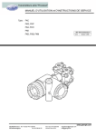
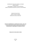
CONFIRMATION OF DELIVERED EQUIPMENT
• Transmitter body (1 set)
(An example of a differential pressure transmitter is shown in the figure on the right.)
• Instruction manual (One copy)
This manual (to be supplied when the instruction manual is required)
,QVWUXFWLRQ0DQXDO
)&;$,,,6(5,(675$160,77(56
7<3(
).$
).%
).&
).'
).(
).*
).3
).+
,1)71)&;$(
• Mounting bracket (One set)
(To be supplied when mounting bracket is required)
or
Used for direct
mount type
INF-TN5FCXA34-E
ix
CONTENTS
INTRODUCTION .......................................................................................................................i
PRODUCT WARRANTY AND MAINTENANCE ................................................................. ii
EMC CONFORMITY ................................................................................................................v
CAUTION ON SAFETY ..........................................................................................................vi
CAUTIONS ON USE............................................................................................................. viii
CONFIRMATION OF YOUR SPECIFICATION ................................................................. viii
CONFIRMATION OF DELIVERED EQUIPMENT ...............................................................ix
CONTENTS ...............................................................................................................................x
1. OUTLINE .............................................................................................................................1
2. OPERATING PARTS AND THEIR FUNCTIONS .............................................................3
3. OPERATION AND SHUTDOWN ......................................................................................6
3.1 Preparation for operation ..................................................................................................................... 6
3.2 Operation ............................................................................................................................................. 7
3.3 Shutdown ............................................................................................................................................. 8
4. ADJUSTMENT ....................................................................................................................9
4.1 Adjustment procedure using the external adjusting screw .................................................................. 9
4.2 Adjustment procedure by local configurator unit with LCD display ................................................ 12
4.2.1 Menu list ...................................................................................................................................... 13
4.2.2 Switching menus .......................................................................................................................... 14
4.2.3 Operating procedure .................................................................................................................... 15
• TAG NO. ................................................................................................................................... 15
• Model code (TYPE) .................................................................................................................. 16
• SERIAL NO. ............................................................................................................................. 17
• Engineering unit ........................................................................................................................ 18
• Range limit ................................................................................................................................ 18
• Measuring range (LRV, URV) ................................................................................................... 19
• Damping .................................................................................................................................... 21
• Output mode .............................................................................................................................. 22
• Burnout direction....................................................................................................................... 24
• Zero/span calibration ................................................................................................................. 26
• Calibration of output circuit (D/A)............................................................................................ 28
• Self-diagnosis ............................................................................................................................ 29
• Lock of adjustment function...................................................................................................... 30
• Setting of LCD display range .................................................................................................... 31
• Input-output range adjustment (Rerange: adjustment by LRV/ URV change) .......................... 35
• Value and specification of saturation current ............................................................................ 38
• Protective function of set value (Write protect) ........................................................................ 40
x
INF-TN5FCXA34-E
CONTENTS
• History information ................................................................................................................... 41
4.3 Adjustment with HHC ....................................................................................................................... 43
4.3.1 Connection of HHC ..................................................................................................................... 43
4.3.2 Outline of HHC operation ........................................................................................................... 44
4.3.3 Operating procedure .................................................................................................................... 45
TAG.No........................................................................................................................................ 45
Type ............................................................................................................................................. 46
Display of serial No.. ................................................................................................................... 46
Industrial value unit ..................................................................................................................... 47
Range limit................................................................................................................................... 48
Range change (LRV, URV) .......................................................................................................... 48
Damping adjustment .................................................................................................................... 49
Output mode ................................................................................................................................ 50
Burnout direction and value......................................................................................................... 51
Zero/span adjustment ................................................................................................................... 52
Calibration of output circuit (D/A) .............................................................................................. 53
Indication of measured data ......................................................................................................... 54
Self-diagnosis .............................................................................................................................. 54
Printer function ............................................................................................................................ 55
Lock of adjustment function ........................................................................................................ 56
Indication of digital indicator ...................................................................................................... 57
Programmable linearization function .......................................................................................... 60
Rerange (Set LRV/URV calibration) ........................................................................................... 62
Saturation current value and specification ................................................................................... 63
Write protect ................................................................................................................................ 64
History information ..................................................................................................................... 66
5. MAINTENANCE ...............................................................................................................67
5.1
5.2
5.3
5.4
Periodic inspection ............................................................................................................................ 67
Troubleshooting ................................................................................................................................. 68
Replacement of parts ......................................................................................................................... 69
Adjustment after replacement of unit ................................................................................................ 78
6. INSTALLATION AND PIPING .......................................................................................79
6.1 Installation ......................................................................................................................................... 79
6.2 Piping ................................................................................................................................................. 83
7. WIRING ...........................................................................................................................104
7.1 Wiring procedure ............................................................................................................................. 104
7.2 Power voltage and load resistance ................................................................................................... 107
7.3 Grounding ........................................................................................................................................ 107
A1
A2
A3
A4
A5
A6
BUILT-IN ARRESTER ....................................................................................................108
CALIBRATION ...............................................................................................................110
PARAMETER SETTING PRIOR TO DELIVERY .........................................................114
HAZARDOUS LOCATION INSTALLATION INFORMATION ..................................115
HART COMMUNICATION FUNCTION .......................................................................124
USE IN SAFETY INSTRUMENTED SYSTEM ............................................................129
INF-TN5FCXA34-E
xi
1. OUTLINE
The FCX-AIII series transmitter detects the differential pressure or pressure of various fluids, converts it
into a current signal of 4 to 20mA DC and transmits it.
All the adjustment functions are incorporated in the amplifier unit for making adjustments easily and exactly.
Transmitter settings (such as range, damping time constant and self-diagnosis, etc.) can be changed from
an HHC (Hand Held Communicator) or a local configurator unit with LCD display.
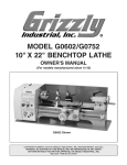
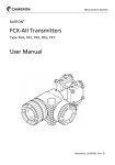
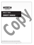
Principle
The operating principle of the FCX-AIII series transmitter is shown in the block diagram below.
The input pressure is changed into an electrostatic capacitance in the detecting unit. The change proportional to the pressure undergoes conditioning and amplification in the amplifier unit, and is then
output as a current of 4 to 20mA DC.
Sensor Unit
Amplifier Unit
FUJI/HART®
Communication
0
EEPROM
Transmitters
Parameters
Analog indicator
(option)
0
%
10
20
40 60 80
EEPROM
Sensor
parameters
Analog to
Digital
Converter
Micro Processor
・Signal conditioning
・Reranging
・Diagnositics
・Communicaiton
4-20mA signarl
Digital to Analog
Converter
Control system
Manual Zero/Span
Adjustment
OUT
DISP
FIX
SPAN
ZERO
abs
LCD digital indicator
(option)
MODE
Micro
Capacitance
Silicon Sensor
HHC
LP
Low
pressure
side
INF-TN5FCXA34-E
HP
High pressure
side
1
Type of electronics unit
There are two types of the electronics unit for the FCX-AIII series transmitter. One is T type (the 4th
digit in the code symbol is 5, 6. 7, 8 or 9) and the other is L type (the 4th digit is S, T, V, W or X).
4TYPE
,TYPE
*) Explanation in this instruction manual is based on the L type.
Measuring range
Model
Absolute
pressure
Pressure
Differential
pressure
Level
Type
FKA
FKH
FKG,
FKB (*1)
FKB (*2)
FKP
FKC
FKD (*1)
FKD (*2)
FKE (*1)
FKE (*2)
Measurable range
1.6-3000 (kPa abs)
8.125-3000 (kPa abs)
1.3-50000 (kPa)
50-10000 (kPa)
8.125-10000 (kPa)
0.1-3000 (kPa)
0.32-500 (kPa)
3-500 (kPa)
0.32-500 (kPa)
3-500 (kPa)
Environmental protection
IP67 (JIS C0920, IEC60529) and
NEMA 6/6P
Dielectric voltage
Power supply 500V AC
Between output circuit and earth
50/60Hz 1min.
Leak current 5 mA or less
*1 Flange size, 3B (3 inches) 80A or more.
*2 Flange size, 2B (2 inches) 50A or below.
2
INF-TN5FCXA34-E
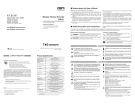
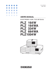
2. OPERATING PARTS AND THEIR FUNCTIONS
FCX-AIII Series transmitter
Terminal unit
Amplifier unit
Analog indicator connector
LCD unit connector
Note) For detail, refer to
page 77.
Process
connection
Zero/Span adjustment
selector switch
Detecting
unit
Indicator
(Digital)
Vent/drain
plug
Amplifer
unit
(Analog)
(Local configurator unit
with LCD display)
OUT
DISP
FLX
OUT
DISP
%
FLX
SPAN
ZERO
abs
%
SPAN
ZERO
abs
Adjusting screw
Description of FCX-AIII Series transmitter
Part name
Description
Detecting unit
Detects pressure, differential pressure or level of fluid.
Amplifier unit
Converts the detected signal into an output signal.
Vent/drain plug
Used for gas discharge or draining.
Process connection
Connects impulse pipes from the process.
Conduit connection
Connects the output cable.
Adjusting screw
Used for adjustment (see Section 3.1).
Terminal unit
External terminal unit to connect an input-output line and ground wire
Amplifier unit
Part name
Description
Analog indicator connector
Used for connecting an analog indicator.
LCD unit connector
Used to connect the digital indicator or the local configurator unit with
LCD display.
Indicator (option)
The analog or digital indicator, or the local configurator unit with LCD
display can be mounted.
Zero/Span adjustment
selector switch
Used to select the function (zero/span) to be adjusted by the external
adjusting screw.
Terminals
Symbol
Description
Connects the output cable.
Used for checking the output current or connecting a separated
indicator. (Note).
Note) Impedance of indicator must be less than 12 Ω (Ohm).
An external terminal used for grounding.
INF-TN5FCXA34-E
3
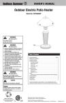
Mode indicating function of digital indicator
OUT
DISP
%
FIX
SPAN
ZERO
abs
Mode indication
Mode
%
When indicated
When not indicated
% output
Actual scale
ZERO
External zero adjustment possible
External zero adjustment impossible
SPAN
External span adjustment
possible
External span adjustment impossible.
Digital indicator
Digital indicator LIN display
DISP
OUT
FIX
abs
display
output
LIN output
Fixed current mode
Measurement mode
The transmitter is in operation
(blinking).
The transmitter is not in operation.
Absolute pressure
Gauge pressure
Output value < Zero
Output value ≥ Zero
(a part of unit indicator)
4
INF-TN5FCXA34-E
Modes of the local configurator unit with LCD display and functions of the 3 push button key switches
Plus key
Minus key
OUT
DISP
%
FIX
SPAN
ZERO
abs
Mode key
MODE
Normal mode (normal mode for indicating a measured value)
"LINKING
-EASUREDVALUE
4HETRANSMITTER
ISBEING
OPERATED
30!.
* For status indication in the normal mode, refer to the previous section “Mode indicating function of
digital indicator.”
Setting mode (functions of the 3 push button key switches)
Lighting
(The setting of
the transmitter is
being adjusted.)
Item No.
Item name
Functions of the 3 push button key switches
Name
Main function
Mode key
Switches between the normal and setting modes.
Minus key
Changes an item No. or item name to the minus (decrease) direction.
Plus key
Changes an item No. or item name to the plus (increase) direction.
* Refer to Section 4.2 “Adjustment procedure by the local configurator unit with LCD display” for
details.
INF-TN5FCXA34-E
5
3. OPERATION AND SHUTDOWN
3.1 Preparation for operation
Before operating the transmitter, be sure to perform the following checks and procedures. While adjusting the explosion-proof transmitter in a hazardous area, do not open the covers of the transmitter
and terminal.
Preparation procedure
(1) Check for liquid or gas leakage from the process connection,
etc. by applying soapy water or the like.
(2) Check the signal wiring according to the “Terminal block
connection diagram” shown in 7.1.
(3) Vent gas from the transmitter in the case of liquid measurement.
Important
When the plant requires chemical cleaning at the start of operation, be sure to
close the valve of the transmitter to prevent entry of cleaning liquid into the
pressure receiving unit.
(4) Perform zero point adjustment.
Zero point check
Turn on the power to the transmitter.
Check the output signal of the transmitter by connecting a DC ammeter across CK+ and CK– of the
terminal block.
After ten minutes or longer, adjust the transmitter output current to 4 mA (zero adjustment).
(See below.)
Zero adjustment
(1) Adjustment by zero adjustment screw
Adjust zero point of the transmitter to 4 mA
by turning the zero adjustment screw.
Fine adjustment
: turning slowly
(approximately 5sec per turn)
Rough adjustment : turning quickly
(approximately 1sec per turn)
Increase
Decrease
* Refer to “Zero adjustment” in Section 4.1 “Adjustment procedure using the external adjusting
screw” for details.
(2) If using the local configurator unit with LCD display, refer to “A: Zero/span adjustment” in Section 4.2.1 “Menu list” in Section 4.2 “Adjustment procedure by the local configurator unit with
LCD display.”
(3) Adjustment by HHC
Refer to “Zero/span calibration” in section 4.3 “Adjustment wiht HHC”.
Important
6
1. After adjustment of the transmitter, it should be kept energized for about 10
seconds to write the adjustment results into memory.
2. Use a blade-edge screwdriver for adjusting the zero adjustment screw.
INF-TN5FCXA34-E
3.2 Operation
(1) Operation of differential pressure transmitter
Set the operating status by manipulating the equalizing valve.
Stop valve
on the low
pressure side
Make sure the equalizing valve is open.
Open
Equalizing
valve
Stop valve
on the high
pressure side
Open the stop valve on the high pressure side slowly.
Open
Close
Close the equalizing valve.
Open
Finally, open the stop valve on the low pressure side
slowly.
(2) Operation of pressure transmitter
Open the valve slowly to apply a pressure. When a pressure is applied, the transmitter is set in
the operating status.
Open the valve slowly.
Check of operating status
Use a field indicator, receiving instrument or HHC to check the operating status.
INF-TN5FCXA34-E
7
3.3 Shutdown
(1) Shutdown of differential pressure transmitter
Set the shutdown status by manipulating the equalizing valve.
Turn off power supply.
Close the stop valve on the high pressure side (H side) slowly.
Close
Open
Open the equalizing valve.
Close
Close the stop valve on the low pressure side (L side) slowly.
(2) Shutdown of pressure transmitter
Close the valve slowly to stop applying a pressure. The transmitter is set in the measurement stop
status.
#LOSETHEVALVESLOWLY
Important
Before a long shutdown, discharge the process fluid and drain completely from
the transmitter. (Loosen the vent drain plug.)
This is to protect the transmitter from freezing, corrosion, etc.
Vent/drain plug
Process fluid discharge
8
INF-TN5FCXA34-E
4. ADJUSTMENT
4.1 Adjustment procedure using the external adjusting screw
Do not open the cover from amplifier case to make following adjustments with
DANGER active DC power supply in hazardous area.
For changing the measuring range, carry out zero adjustment first, and span adjustment next. (If zero
adjustment is performed after span adjustment, the 100% point may not be adjusted correctly.)
Accordingly, the zero point (LRV) or span (URV-LRV) of the measuring range is changed. To confirm
the changed values, display the measuring range (LRV, URV) by the HHC or the LCD unit with three
push buttons after this operation.
Zero adjustment
To adjust the zero point of the transmitter, set the selector switch to “ZERO” and adjust the zero point
by the external adjusting screw.
Before touch the selector switch, touch the metallic part of the case to prevent
CAUTION electrostatic discharge.
(1) Set the selector switch to “ZERO.”
(2) Apply standard input pressure corresponding to new Lower Range Value.
(3) Adjust output signal to 4.00mA by turning the external adj. screw.
Set switch to “zero” position
for zero calibration
External adj. screw
SPAN
ZERO
Increase
Decrease
Fine adjustment
: turning slowly
(approximately 5sec per turn)
Rough adjustment : turning quickly
(approximately 1sec per turn)
Important
INF-TN5FCXA34-E
1. After adjustment, the transmitter should be kept energized for about 10 seconds to write the adjustment results into memory.
2. If the lock function is effective (see p. 30) the transmitter cannot be adjusted
by the external adjusting screw.
9
For zero suppression or elevation ranges, apply the specified LRV pressure in advance and
adjust the output signal to 4.00mA using the external adj. screw.
2EMARKS
3UPPRESSION2ANGE
3EETHEDIAGRAMATRIGHT
%LEVATION2ANGE
/UTPUT
%LEVATION2ANGE
3EETHEDIAGRAMATRIGHT
3UPPRESSION
2ANGE
)NPUT
,260RESSURE 5260RESSURE
.OTE4HISDIAGRAMINDICATESNORMALACTION
Span adjustment
The measuring range for each transmitter is determined according to its type.
To adjust the span, set the selector switch to “SPAN” and adjust the span by the external adjusting
screw.
Before touch the selector switch, touch the metallic part of the case to prevent
CAUTION electrostatic discharge.
(1)
(2)
(3)
(4)
Set the selector switch to “SPAN.”
Apply the standard input pressure.
Adjust output to 20.00mA by turning the external adj. screw.
Set the pressure back to the minimum measuring pressure and check that the output is 4 mA.
Set switch to “zero”
for zero calibration
External adj. screw
SPAN
ZERO
Increase
Decrease
Fine adjustment
: turning slowly
(approximately 5sec per turn)
Rough adjustment : turning quickly
(approximately 1sec per turn)
10
INF-TN5FCXA34-E
After adjusting the span as mentioned above, set the selector switch back to “Zero” before using
the transmitter.
INF-TN5FCXA34-E
SPAN
ZERO
Important
After adjustment, the transmitter should be kept energized at about 10 seconds
to write the adjustment parameter into memory.
11
4.2 Adjustment procedure by local configurator unit with
LCD display
Do not open the cover from amplifier case to make following adjustments with active
DANGER DC power supply in hazardous area.
You can use various functions of the FCX- AIII series transmitter with 3 push button key switches by
installing the local configurator unit with LCD display in the transmitter.
Cautions for operation
To change the set value, check that the control loop of the host system (such as an in-
DANGER strumentation system) can be performed manually.
Key switch name
key
(plus key)
key
(minus key)
OUT
DISP
%
FIX
SPAN
ZERO
abs
M key
(mode key)
MODE
Mode switching
"LINKING
,IGHTING
.ORMALMODE
4WOSECONDS
ORMORE
3ETTINGMODE
• To switch the normal mode to the setting mode:
Press the
key for two seconds or more.
• To switch the setting mode to the normal mode:
Press the
key for two seconds or more on the item name selection screen.
If no operation is performed for three minutes in the setting mode, the mode is automatically
switched back to the normal mode.
Cautions for setting
• Setting error
If a setting error occurs, an error display shown on the lower right appears in the display.
Press the
key to return to the item name selection screen in the setting mode.
• Adjusting screw
You cannot use the adjusting screw in the setting mode.
• HHC transmission
After switching to the setting mode, you can input commands during the item name selection
screen.
After switching to the setting mode, you cannot input commands after selecting items.
12
INF-TN5FCXA34-E
4.2.1 Menu list
The following are the menu items. Adjust each setting as required.
Item (large classification)
Item name
Description
Relevant page
1 TAG No.
1. TAG
Display and setting of TAG No. (*1)
15
2 Model code
2. TYPE
Display and setting of type (*1)
16
3-1. SERIAL N
Display of serial No.
17
3 Serial No.
3-2. VER
Display of transmitter software version
17
4 Engineering unit
4. UNIT
Display and change of engineering unit (*1)
18
5 Range limit
5. URL
Display of maximum measuring range
18
6-1. LRV
Change of LRV (lower range value of measuring range = 0% point) (*1)
19
6-2. URV
Change of URV (upper range value of measuring range = 100% point)
(*1)
20
7. DAMP
Change of damping time constant (*1)
21
8-1. OUT Md
Change of output mode (*3) (*1)
22
8-2. CUT Pt
Setting of low flow rate cut point (*3) (*1)
22
8-3. CUT Md
Setting of low flow rate cut mode (*3) (*1)
23
9-1. BURNOT
Change of burnout direction (*1)
24
6 Measuring range
7 Damping
8 Output mode
9
Direction and value of
burnout
A Zero/span calibration
B
Output circuit
calibration
D Self-diagnosis
F
G
Locking of adjustment
functions
LCD display range
setting
Input-output range
I
adjustment
J
K
9-2. OVER
Chang of output value when burnout direction = OVERSCALE (*4) (*1)
24
9-3. UNDER
Chang of output value when burnout direction = UNDERSCALE (*5) (*1)
25
A-1. ZERO
Zero calibration (*6) (*2)
26
A-2. SPAN
Span calibration (*6) (*2)
27
b-1. 4mAAdj
4 mA calibration (*8) (*2)
28
b-2. 20mAAdj
20 mA calibration (*8) (*2)
28
b-3. FIXcur
Constant current output (*8)
28
d-1. AMPTMP
Display of internal temperature of transmitter
29
d-2. ALMCHK
Display of self diagnosis.
29
F. LOCK
Locking and unlocking of the adjusting screw and the adjustment function
in the setting mode (*1)
30
G-1. LDV
LDV (Lower Display Value) setting (*1)
31
G-2. UDV
UDV (Upper Display Value) setting (*1)
32
G-3. DP
DP (number of digit after Decimal Point) setting (*1)
32
G-4. LcdUnit
LcdUnit (LCD Unit Code) setting (*1)
33
G-5. LcdoOpt
LcdOpt (LCD Option) setting (*1)
34
I-1. LRVAdj
Zero adjustment by range (LRV) change (*6) (*2)
35
I-2. URVAdj
Span adjustment by range (URV) change (*6) (*2)
36
J-1. SAT LO
Change of saturation current value (lower limit) (*7) (*1)
38
Value and specification J-2. SAT HI
of saturation current
J-3. SPEC
Protective function of
set value
L History information
Change of saturation current value (upper limit) (*7) (*1)
39
Selection (Nomal specification/expanded specification) of specifications
of burnout & saturation current (*1)
39
K. GUARD
Setting and cancellation of set value protection (write protect) (*9)
40
L-1. HisZERO
Display of zero calibration data for users
41
L-2. HisSPAN
Display of span calibration data for users
L-3. HisCLEAR Clearing of zero/span calibration data (*1)
41
41
L-4. HisAMP
Display of min/max of amplifier temperature history information
42
L-5. HisCELL
Display of min/max of cell temperature history information
42
*1: If the write protect is selected at “K. GUARD,” the display for selecting whether the setting will be performed does not appear, but “GUARD”
appears. You cannot change the value in this condition.
*2: If the adjustment function is locked at “F.Lock” or the write protect is selected at “K. GUARD,” the item names is not displayed.
*3: Only differential pressure transmitters have this function. Other transmitters do not display the item name.
*4: This item is valid only if when the burnout direction = “OVERSCALE.” If not, the item name is not displayed.
*5: This item is valid only if when the burnout direction = “UNDERSCALE.” If not, the item name is not displayed.
*6: This item is valid only if polygonal line correction is invalid. If the polygonal line correction is valid or the equipment is defective, the item
name is not displayed.
*7: You cannot change the value if the nomal specification is selected at “J-3: SPEC.”
*8: In the multidrop mode, this item is invalid and the item name is not displayed.
*9: If the write protect function (with a password) is selected by the HHC, the item name is not displayed.
INF-TN5FCXA34-E
13
4.2.2 Switching menus
Setting mode (item name selection screen ↔ display and setting of each item)
key for a few seconds to switch the normal mode to the setting mode (item name sePress the
lection screen).
Press the
key for a few seconds to switch the setting mode (item name selection screen) to the
normal mode.
After selecting an item with the / keys, press the ) key (in normal operation) to move to
each item.
Normal mode
(A measured value is displayed.)
Press the
key for two seconds or more.
Setting mode
Item name selection screen
key (in normal operation)
Setting mode
Display and setting of each item
You can move to a next
upper item with the
key.
You can move to a next
lower item with the
key.
1. TAG
2. TYPE
3-1. SERIAL N
3-2. VER
4. UNIT
5. URL
6-1. LRV
6-2. URV
7. DAMP
8-1. OUT Md
8-2. CUT Pt
8-3. CUT Md
9-1. BURNOT
9-2. OVER
9-3. UNDER
A-1. ZERO
A-2. SPAN
B-1. 4mAAdj
B-2. 20mAAdj
B-3. FIXcur
D-1. AMPTMP
D-2. ALMCHK
F. LOCK
G-1. LDV
G-2. UDV
G-3. dP
G-4. LcdUnit
G-5. LcdOpt
I-1. LRVAdj
I-2. URVAdj
J-1. SAT LO
J-2. SAT HI
J-3. SPEC
K. GUARD
L-1. HisZERO
L-2. HisSPAN
L-3. HisCLEAR
L-4. HisAMP
L-5. HisCELL
14
1. Display and setting of TAG No.
2. Display and setting of type
3-1. Display of serial No.
3-2. Display of transmitter software version
4. Display and change of engineering unit
5. Display of maximum measuring range
6-1. Change of LRV (lower range value of measuring range = 0% point)
6-2. Change of URV (upper range value of measuring range = 100% point)
7. Change of damping time constant
8-1. Change of output mode
8-2. Setting of low flow rate cut point
8-3. Setting of low flow rate cut mode
9-1. Change of burnout direction
9-2. Chang of output value when burnout direction = OVERSCALE
9-3. Chang of output value when burnout direction = UNDERSCALE
A-1. Zero calibration
A-2. Span calibration
B-1. 4 mA calibration
B-2. 20 mA calibration
B-3. Constant current output
D-1. Display of internal temperature of transmitter
D-2. Display of self-diagnosis.
F. Locking and unlocking of the adjusting screw and the adjustment function in the setting mode
G-1. LDV (Lower Display Value) setting
G-2. UDV (Upper Display Value) setting
G-3. DP (Digit Number Under Decimal Point) setting
G-4. LcdUnit (LCD Unit Code) setting
G-5. LcdOpt (LCD Option) setting
I-1. Zero adjustment by range (LRV) change
I-2. Span adjustment by range (URV) change
J-1. Change of saturation current value (lower limit)
J-2. Change of saturation current value (upper limit)
J-3. Selection (nomal specification/expanded specification) of specifications of burnout & saturation current
K. Setting and cancellation of set value protection (write protect)
L-1. Display of zero calibration data for users
L-2. Display of span calibration data for users
L-3. Clearing of zero/span calibration data
L-4. Display of min/max of amplifier temperature history information
L-5. Display of min/max of cell temperature history information
INF-TN5FCXA34-E
4.2.3 Operating procedure
TAG NO.
To set the TAG NO. of each field device, use
the procedures shown in the following diagram. TAG NO. can be inputted up to 26
character of alphanumeric codes.
M
①
• Press the
key on the screen to display the TAG No. setting ().
• Input alphanumeric characters as required
with the
and
keys on the screen .
Functions of the keys:
key: To input characters at the cursor
position
③
(0 to 9, space, A to Z, –)
key: To move the cursor position to the
next
(1 2 3 ... 26 1)
②
M
#ANCELTHESETTING
M
3AVETHESETTING
Note) Characters other than numerical characters, capital letters of the alphabet,
④
space, and “–” are displayed as “*.”
Initial six characters are displayed.
(The cursor position is displayed by a
vertical bar.)
To display the seventh and following
characters, scroll the characters to the
left. (The cursor position (far right) is
displayed as a number.)
The cursor position is 1 in the example
. (Number 1 is input as the first
character.)
The cursor position is 8 in the example
. (Number 8 is input as the eighth
character.)
If HART is selected, the initial eight
characters are treated as TAG information.
• Select whether the TAG No. setting is
saved on the screen .
Press the
key to save the TAG No. setting.
or
key to cancel the setting.
Press the
INF-TN5FCXA34-E
15
Model code (TYPE)
Model code of field device is displayed and
changed (example of differential pressure
transmitter).
M
①
M
#ANCELTHESETTING
M
3AVETHESETTING
• Press the
key on the screen to display
the
model
code setting screen ().
②
• Input alphanumeric characters as required
with the
and
keys on the screen .
Functions of the keys:
key: To input characters at the cursor
position.
(0 to 9, space, A to Z, –)
③
key: To move the cursor position to the
next.
(1 2 3 ... 16 1)
Note) Characters other than numerical characters, capital letters of the alphabet,
space, and “–” are displayed as “*.”
④
Initial six characters are displayed.
(The cursor position is displayed by a
vertical bar.)
To display the seventh and following
characters, scroll the characters to the
left. (The cursor position (far right) is
displayed as a number.)
The cursor position is 2 in the example
. (“K” is input as the second character.)
The cursor position is 8 in the example
. (“5” is input as the eighth character.)
• Select whether the type setting is saved on
the screen .
Press the
key to save the type setting.
or
key to cancel the setting.
Press the
* Description of the displays on the first line
on the item name selection screen ()
: Differential pressure transmitter
: Pressure (gauge pressure) transmitter
: Absolute pressure transmitter
16
INF-TN5FCXA34-E
SERIAL NO.
SERIAL NO.(8 letters) and transmitters software version are displayed.
M
①
M
M
④
⑤
M
INF-TN5FCXA34-E
Display of SERIAL No.
key on the screen to dis② • Press the
play the SERIAL No.()
Note) Characters other than numerical
characters, capital letters of the alphabet, space, and “–” are displayed
as “*.”
Initial six characters are displayed.
③
(The cursor position is displayed by
a vertical bar.)
To display the seventh and following
characters, scroll the characters to
the left by pressing key. (The cursor position (far right) is displayed
as a number.)
Display of transmitter software version
• To display the software version (), press
the
key on the screen .
17
Engineering unit
M
①
②
• To display the screen for changing the enkey on
gineering unit ( ), press the
the screen .
and
• Select an engineering unit with the
keys on the screen .
Important
③
M
#ANCELTHESETTING
The engineering unit is set according to the
range as ordered, but the display resolution
lowers depending on the unit being set.
Available unit for FCX-AIII
(The units with * cannot be used because
they are not legal units in Japan.)
M
3AVETHESETTING
mmH2 O
cmH 2 O
mH 2 O
g/cm 2
kg/cm2
Pa
hPa
kPa
MPa
mbar
bar
psi
inH 2 O
ftH 2 O
mmAq
cmAq
mAq
mmWC
cmWC
mWC
mmHg
cmHg
mHg
inHg
< Torr >
< atm >
④
M
①
M
②
Note: The mark < > is settable for absolute pressure transmitter only.
Range limit
Indicates the maximum measuring range of
this transmitter.
• To display the range limit value (), press
key on the screen .
the
Note) If “UUUUU” is displayed as a URL
value, the unit is not supported.
18
INF-TN5FCXA34-E
Measuring range (LRV, URV)
LRV: Lower range value (0% point)
M
URV: Upper range value (100% point)
ZERO
Selectable setting range
②
/UTPUTM!
2EVERSE
ACTION
526
ZERO
③
M
ZERO
,26
,26 .ORMAL
ACTION
)NPUT
①
526
-AXIMUMMEASURINGRANGE
Note) If the set value of the LRV is outside
the range, an error also occurs in the
URV setting, and vice versa.
The maximum setting range is ±99999.
The URV may exceed the upper limit
depending on the change of the UNIT.
If that happens, change the URV first.
Change of LRV (lower limit of the measuring range = 0% point)
key on the screen to dis• Press the
play the screen for setting the zero point
range ().
and
• Input the numerical values with the
keys on the screen .
Functions of the keys:
⑤
key: To decrease the value.
key: To increase the value.
Range: –99999 ≤ LRV ≤ 99999
Note) If “UUUUU” is displayed as a LRV
value, the unit is not supported.
• To set the decimal point position, press the
key on the screen . “P” is displayed
at the left of the unit name () and you
can set the decimal point position with the
and
keys.
key: To move the decimal point position to left
key: To move the decimal point position to right
• Select whether the LRV setting is saved on
the screen .
key to save the zero point
Press the
range setting.
Press the
or
key to cancel the setting.
④
M
#ANCELTHESETTING
M
3AVETHESETTING
INF-TN5FCXA34-E
19
Change of URV (upper limit of the measuring range = 100% point)
M
①
M
M
#ANCELTHESETTING
• Press the
key on the screen to display the screen for setting the 100% point
SPAN
().
• Input the numerical values with the
and
②
keys on the screen .
Functions of the keys:
key: To decrease the value.
key: To increase the value.
Range: –99999 ≤ URV ≤ 99999
Note) If “UUUUU” is displayed as a URV
SPAN
value, the unit is not supported.
•
To
set
the decimal point position, press the
③
key on the screen . “P” is displayed
at the left of the unit name () and you
can set the decimal point position with the
and
keys.
key: To move the decimal point posiSPAN
tion to left
key: To move the decimal point posi④
tion to right
• Select whether the URV setting is saved on
the screen .
Press the
key to save the 100% point
setting.
or
key to cancel the setting.
Press the
M
3AVETHESETTING
20
⑤
INF-TN5FCXA34-E
Damping
M
①
②
In the case where the process input fluctuation is large, the vibration of the installation
site is large, and minute differential pressure
is measured, if the output fluctuation is large,
set appropriate damping time constant to
suppress the output fluctuation.
Change of damping time constant
③
M
(Cancel the setting)
M
(Save the setting)
④
Note 1) It is settable to two places of
decimals point After setting, exact
numbers may not be shown due to
resolution capability.
• Press the
key on the screen to display the screen for changing the damping
time constant ().
• Input the damping time constant with the
and
keys on the screen . Press the
key to decrease the value and press the
key to increase the value.
Settable range: 0.06 to 32.0 sec Note 1)
• Select whether the damping time constant
setting is saved on the screen .
key to save the damping time
Press the
constant setting.
or
key to cancel the setting.
Press the
About the output fluctuation of the transmitter caused by vibration and damping
1) Magnitude of output fluctuation (oscillation) caused by vibration
If the transmitter is mounted to a place subject to severe vibration, output fluctuation (oscillation) may increase. Since the transmitter uses oil as internal pressure transmitting medium,
if acceleration is caused by vibration, internal pressure is generated in accordance with the
acceleration value, thus resulting in the output fluctuation. The magnitude of output oscillation may become the value shown below at the maximum.
Oscillation frequency: 10 to 150 Hz
Within ±0.25% of URL/(9.8m/s2)
2) Damping
The output fluctuation (oscillation) of the transmitter in an environment subject to vibration
can be damped by setting appropriate damping time constant using the HHC. The following
table shows the effect of damping on the vibration of 10Hz where the output fluctuation becomes the maximum.
Guideline of the effect of damping on the output fluctuation (oscillation)
Damping set value [sec]
Damping of output oscillation
1.2
1/3 or lower
4.8
1/5 or lower
19.2
1/10 or lower
Remarks
Note) In the oscillation range from 10 to 150Hz, the output fluctuation (oscillation) becomes the
maximum at 10Hz, that is, the lowest frequency.
INF-TN5FCXA34-E
21
Output mode
The output mode is used to select the proportional mode (proportional to input differential pressure) or square root extraction
mode (proportional to flow rate) for the output signal (4 to 20 mA) of the differential
②
pressure transmitter.
M
①
#ANCELTHESETTING
In the square root extraction mode, you can
set the cut point of low cut and the modes
below the cut point.
M
Change of output mode
key on the screen to dis• Press the
play the screen for changing output mode
().
• You can select the proportional or square
root extraction mode on the screen .
Select LIN (proportional mode) or SQR
(square root extraction mode) with the
%
key and press the
key.
or
• Select whether the output mode setting is
saved on the screen .
⑤
key to save the output mode
Press the
setting.
or
key to cancel the setting.
Press the
③
②
M
3AVETHESETTING
M
④
%
M
#ANCELTHESETTING
M
3AVETHESETTING
Low cut point setting
If you select the square root mode, set the
⑥
low cut point.
Cut point is adjustable within the range of
0.00 to 20.00%. Note that if the cut point is
set to a small value around 0%, even a minute differential pressure change causes a
sudden output fluctuation. The cut point is
⑦ used for stabilizing output near 0% when the
square root extraction mode is selected for
output signal.
• Press the
key on the screen to display the screen for setting the low cut point
().
• You can set and change the low cut point
by inputting the numerical values with the
and
keys on the screen .
Settable range: 0.00 to 20.0%
• Select whether the cut point setting is
saved on the screen .
Press the key to save the cut point setting.
or
key to cancel the setting.
Press the
22
INF-TN5FCXA34-E
Low cut mode setting
There are two modes; in one mode, proportional output is selected for output below a
cut point (Fig. A) and in the other mode, output is forcibly reduced to 0% for output below a cut point (Fig. B).
M
⑧
⑨
/UTPUT
/UTPUT
#ANCELTHESETTING
,OWCUT
POINT
M
&IG!7ITHLINEAR
OUTPUTSELECTEDIN
LOWCUTMODE
⑩
M
3AVETHESETTING
INF-TN5FCXA34-E
,OWCUT
POINT
$IFFERENTIAL
INPUT
&IG"7ITHZERO
OUTPUTSELECTEDIN
LOWCUTMODE
$IFFERENTIAL
INPUT
⑨
• Press the
key on the screen to display the screen for changing the outputs
below the cut point ().
• Select LIN (linear) or ZERO on the screen
with the or key and press the
key.
• Select whether the low cut point setting is
saved on the screen .
key to save the low cut point
Press the
setting.
or
key to cancel the setting.
Press the
23
Burnout direction
Used for selecting output at occurrence of a
fault in the detecting unit.
M
Change of burnout direction
①
②
NotUse Output hold
OVER OVERSCALE
UNDER UNDERSCALE
(Cancel the setting)
key on the screen to dis• Press the
play the screen for changing the burnout
direction ().
②
• Select NotUse, OVER or UNDER on the
screen (2) with the
or
key and press
key.
the
• Select whether the burnout direction setting is saved on the screen .
Press the
key to save the burnout direc②
tion setting.
or
key to cancel the setting.
Press the
M
③
M
(Save the setting)
M
④
M
(Cancel the setting)
M
(Save the setting)
Change of burnout current when OVER
(OVERSCALE) is selected for the burnout
direction
This display appears if you select “OVER”
for the burnout direction.
key on the screen to dis• Press the
⑤
play the screen for changing the burnout
current for OVERSCALE ().
• You can change the burnout current with
the
and
keys on the screen .
Settable range:
Saturation current value (upper limit) ≤
Burnout (OVER) ≤ 22.5 mA
⑥
Note) You can change the saturation current value (upper limit) setting at
“J: Value and specification of saturation current.”
• Select whether the burnout current setting
is saved on the screen .
⑦
Press the
key to save the burnout current setting for OVERSCALE.
or
key to cancel the setting.
Press the
See the next page for the procedure when UNdER is
selected.
24
INF-TN5FCXA34-E
Change of burnout current when UNDERSCALE is selected for the burnout direction
This display appears if you select “UNDER”
for the burnout direction.
M
⑧
M
#ANCELTHESETTING
key on the screen to dis• Press the
play the screen for changing the burnout
⑨
current for UNDERSCALE ().
• You can change the burnout current with
and
keys on the screen .
the
Settable range:
3.2 mA ≤ Burnout (UNDER) ≤ Saturation current value (lower limit)
⑩ • Select whether the burnout current setting
is saved on the screen .
key to save the burnout curPress the
rent setting for UNDERSCALE.
or
key to cancel the setting.
Press the
M
3AVETHESETTING
INF-TN5FCXA34-E
⑪
Note) You can change the saturation current
value (lower and upper limits) setting
in “J. Value and specification of saturation current.”
25
Zero/span calibration
,IGHTING
M
Zero and span are adjustable by applying an
actual pressure.
%
ZERO
①
,IGHTING
M
Important
②
M
3AVE
THESETTING
,IGHTING
M
,IGHTING
1. After performing a zero calibration, perform a span calibration.
2. If you input the value that exceeds the
adjustable range, the setting will not be
changed even after the setting is saved.
%
Adjustable range
ZERO "LINKING
Zero calibration: within ±40% of the
maximum span
③
Span calibration: within ±20% of the
set span
Zero calibration
OR
%
ZERO
#ANCEL
THESETTING
④
"LINKING
M
⑤
26
• Press the
key on the screen to select
the zero calibration mode.
The measured value and unit on the screen
( ) are the same as those in the normal
mode and “” and “ZERO” light up.
• Apply the actual input pressure on the
screen . After checking the measured
key.
value, press the
• “ZERO” blinks on the screen . Press the
key on the screen to perform a zero
calibration at the input pressure at the time.
To perform a zero calibration at a point
other than 0%, input an appropriate set
and
keys,
value (%) ( ) with the
key.
and press the
Settable range:
–1.000%CS ≤ PL ≤ 100.000%CS
Lower limit of adjustment point × 100
PL =
Setting range
* CS is an abbreviation of Calibrated Span,
which means an actual measurement
range.
• Select whether the zero calibration value
setting is saved on the screen .
Press the
key to save the zero calibration value setting and return to the screen
.
Press the
or
key to cancel the setting
and return to the screen .
• Check that the zero calibration was performed as intended.
Press the
key to perform a zero calibration again.
or
key to move to the next
Press the
screen for item name selection.
INF-TN5FCXA34-E
Span calibration
,IGHTING
M
⑥
M
,IGHTING
3AVE
THESETTING
M
OR
#ANCEL
THESETTING
M
,IGHTING
• Press the
key on the screen to select
the span calibration mode.
The measured value and unit on the screen
%
SPAN ,IGHTING
( ) are the same as those in the normal
mode and “” and “SPAN” light up.
⑦
• Apply the actual input pressure on the
screen . After checking the measured
value, press the
key.
• “SPAN” blinks on the screen . Press the
key on the screen to perform a span
%
calibration
at the input pressure at the time.
SPAN "LINKING
To perform a span calibration at a point
other than 100%, input an appropriate set
⑧
and
keys,
value (%) ( ) with the
key.
and press the
Settable range:
0.000%CS ≤ PH ≤ Saturation current (upper limit) set value (%CS)
%
SPAN
Upper limit of adjustment point × 100
PL =
Setting range
•
Select
whether
the span calibration value
⑨
"LINKING
setting is saved on the screen .
M
Press the
key to save the span calibration value setting and return to the screen
.
Press the
or
key to cancel the setting
and return to the screen .
• Check that the span calibration was per⑩
formed as intended.
Press the
key to perform a span calibration again.
or
key to move to the next
Press the
screen for item name selection.
* CS is an abbreviation of Calibrated Span,
which means an actual measurement range.
INF-TN5FCXA34-E
27
Calibration of output circuit (D/A)
The output circuit (D/A) should be calibrated
by the following procedure when necessary.
M
Lighting
'
FIX
①
②
M
(Calibration)
M
Lighting
'
FIX
③
④
M
(Calibration)
M
⑤
⑥
M
(Setting)
⑦
M
FIX
M
*When a display
other than EXITFIX
is selected.
Lighting
*Press the M key
when EXIT FIX is displayed.
FIX
Blinking
Note) If 3.1mA is set, FiX sign is blinking which
indicate EXIT FIX.
28
⑧
⑨
Make calibration wiring transmitter according to “Calibration” in Appendix A2, and
calibrate the output circuit using the following procedure.
4 mA adjustment
• Press the
key on the screen to display the screen for calibrating the constant
current mode 4 mA ().
• Perform a calibration for 4 mA on the
screen with the
and
keys.
key to
• After the calibration, press the
move to the screen for calibration of 20 mA.
20 mA adjustment
key on the screen to dis• Press the
play the screen for calibrating the constant
current mode 20 mA ().
• Perform a calibration of 20 mA on the
screen with the
and
keys.
key to
• After the calibration, press the
move to the constant current output screen.
Constant current output
key on the screen to dis• Press the
play the screen for performing a constant
current output ().
• Input a current to be output on the screen
with the and keys.
Output value range
3.2 mA 21.6 mA EXITFIX (cancelation) 3.2 mA
key on the screen to output
• Press the
the input current value and the screen
appears.
or
key to cancel the input
Press the
and return to the screen .
or
key on the screen .
• Press the
FIX blinks and you can reset the constant
current output value (). Input a set value
and
keys, press the
key
with the
to return to the screen , and output the
reset current.
• Select EXITFIX on the screen and
key to terminate the constant
press the
current output and move to the item name
selection screen.
Note) If nothing is input for three minutes in
the status of the constant current output, the screen returns to the normal
mode with the constant current output
kept. You can confirm it by the lighted
FIX. Select the setting mode again.
Select “FIX cur” on the display in
the items of “6-3. FIX cur” and press
key to terminate the constant
the
current output.
INF-TN5FCXA34-E
Self-diagnosis
Self-diagnosis display shows the internal
temperature of the transmitter and the failure
description.
M
①
Internal temperature of the transmitter
• Press the
key on the screen to display the screen of internal temperature of
the transmitter ().
When a temperature alarm is issued,
“TEMP” is changed to “ALM.”
(This corresponds to “AMP TMP” of “Error
display of self-diagnosis” in the following
table.)
④
If the temperature cannot be measured due
to defective internal data, “IMPOSS” is
displayed.
(This corresponds to any of “RAM ER”,
“PAR ER” or “AMP EP” of “Error display
of self-diagnosis” in the following table.)
②
M
M
③
M
Display of self-diagnosis results
• Press the
key on the screen to show
the self-diagnosis results ().
Press the
and
keys to display errors
sequentially.
See the following table “Contents of message” for the errors of the transmitter.
[Contents of message]
As a result of self-diagnosis, the message below is appeared on the LCD display, when there are trouble in
the transmitter. For each error, its cause and remedy are suggested.
Error display of
self-diagnosis
C1 ERR
~
C9 ERR
Display in
normal mode
FL-1
RAM ER
FL-1
PAR ER
AMP EP
CEL EP
AMP TMP
CEL TMP
FL-2
FL-3
T. ALm
T. ALm
OVER
UNDER
INF-TN5FCXA34-E
Cause
Error of detecting unit
Calculation parameter (RAM)
error
Error of magnitude relation of
temperature data
EEPROM error on amplifier side
EEPROM error on cell side
Amplifier temperature error
Cell temperature error
Input pressure: J-2, saturation
current (Hi) or higher
Input pressure: J-1, saturation
current (Lo) or lower
Remedy
Check the wiring between the
detecting unit and transmitter.
If the error is not recovered,
replace the detecting unit.
Replacement of amplifier
Replacement of amplifier
Replacement of detecting unit
Transmitter temperature is
normalized.
Correction of input pressure
Correction of input pressure
29
Lock of adjustment functions
You can lock/unlock the adjustment function
of the local configurator unit as follows.
M
When the adjustment functions are locked,
the external adjusting screw is also locked.
①
#ANCELTHESETTING
M
③
M
3AVETHESETTING
• Press the
key on the screen to display the lock selection screen of adjusting
functions ().
• Select the locking/unlocking of the adjustment functions on the screen with the
and
keys.
Select the locking to lock the adjustment
②
functions of the local configurator unit
with LCD display.
Select the UnLock to cancel the lock of the
adjustment functions of the local configrator unit with LCD display.
• Select whether the locking/unlocking of
the adjustment functions are saved on the
screen .
After selecting the locking/unlocking,
press the
key to save the setting.
or
key to cancel the setting
Press the
and return to the screen .
②
List of adjustment functions locked/unlocked
30
A. Zero/span
calibration
A-1. ZERO
B Output circuit
calibration
b-1. 4mA Adj
I. Input-Output range
adjustment
I-1. LRV Adj
A-2. SPAN
b-2. 20mA Adj
I-2. URV Adj
INF-TN5FCXA34-E
Setting of LCD display range
You can set the indicated value corresponding to 0% (4 mA) and 100% (20 mA) for the
actual scale display of the LCD unit.
M
①
②
M
#ANCELTHESETTING
M
3AVETHESETTING
M
LDV (Setting of the indicated value of 0%
(4 mA))
key on the screen to dis• Press the
play the screen for setting the indicated
value corresponding to 0% ().
• Input the indicated value corresponding to
0% of the actual scale on the screen
with the
and
keys.
③
Functions of the keys:
key: To decrease the value
key: To increase the value
• To set the decimal point position, press the
key on the screen . “P” is displayed
at the right of the unit name () and you
can set the decimal point position with the
and
keys.
④
key: To move the decimal point position to left
key: To move the decimal point position to right
• Select whether the indicated value setting
of 0% is saved on the screen .
key to save the indicated value
Press the
setting.
or
key to cancel the setting.
Press the
Actual scale value setting conditions
│ Saturation current value (Lower limit)
without decimal point │ ≤ 99999
│ Saturation current value (Upper limit)
without decimal point│ ≤ 99999
0 < │ (value corresponding to 100%
without decimal point) – (value corresponding to 0% without decimal point)
│ ≤ 20000
When decimal point is used for values
corresponding to 0% and 100% respectively, the number of digits after the
decimal point should be the same.
INF-TN5FCXA34-E
31
UDV (Setting of the indicated value of 100%
(20 mA))
M
⑤
⑥
M
⑦
(Cancel the setting)
M
M
(Save the setting)
⑧
M
⑨
⑩
(Cancel the setting)
M
M
(Save the setting)
Menu I
Menu I
⑪
• Press the
key on the screen to display the screen for setting the indicated
value corresponding to 100% ().
• Input the indicated value corresponding to
100% of the actual scale on the screen
with the
and
keys.
• Functions of the keys:
key: To decrease the value
key: To increase the value
• To set the decimal point position, press the
key on the screen . “P” is displayed
at the right of the unit name () and you
can set the decimal point position with the
and
keys.
key: To move the decimal point position to left
key: To move the decimal point position to right
• Select whether the indicated value setting
of 100% is saved on the screen .
Press the
key to save the indicated value
setting.
or
key to cancel the setting.
Press the
DP setting (number of digits after Decimal
Point))
Set the number of digits after decimal point
for the LCD indicated value.
• Press the
key on the screen to display the screen for setting the DP ().
• Input the DP on the screen (10) with the
keys.
and
Setting range:
0 ≤ DP ≤ 4
Actual scale value setting conditions
│ Saturation current value (Lower limit)
without decimal point │ ≤ 99999
│ Saturation current value (Upper limit)
without decimal point│ ≤ 99999
0 < │ (value corresponding to 100%
without decimal point) – (value corresponding to 0% without decimal point)
│ ≤ 20000
When decimal point is used for values
corresponding to 0% and 100% respectively, the number of digits after the
decimal point should be the same.
32
Display range
DP=0
-99999 ~ 99999
DP=1
-9999.9 ~ 9999.9
DP=2
-999.99 ~ 999.99
DP=3
-99.999 ~ 99.999
DP=4
-9.9999 ~ 9.9999
• Select whether the DP setting is saved on
the screen .
Press the
key to save the DP setting.
or
key to cancel the setting.
Press the
INF-TN5FCXA34-E
LCD Unit (Setting of the actual scale unit)
M
⑫
#ANCELTHESETTING
M
• Press the
key on the screen
to display the screen for setting the unit ( ).
with the
• Input the unit on the screen
keys.
and
• Select whether the unit setting is saved on
⑬
the screen .
Press the
key to save the unit setting.
or
key to cancel the setting.
Press the
Available unit for FCX-AIII
(The units with * cannot be used because
they are not legal units in Japan.)
M
3AVETHESETTING
⑭
(a)
%(LIN)
NONE(LIN)
MPa
kPa
hPa
Pa
bar
mbar
kg/cm2 g/cm2 mmH2O cmH2O mH2O inH2O ftH2O mmAq cmAq mAq
mmWC cmWC mWC mmHg cmHg mHg
inHg
PSI
<atm> <Torr> (b)
mm
cm
m
in ft The units in parentheses < >
are displayed only when the
absolute pressure transmitter
is used.
(c)
%(SQR)
NONE(SQR)
Nm3/s
Nm3/min
Nm3/h
Nm3/d
m3/s
m3/min
m3/h
m3/d
Nl/s
Nl/min
Nl/h
Nl/d
l/s
l/min
l/h
l/d
gal/s gal/min gal/h gal/d ft3/s
ft3/min ft3/h
ft3/d
bbl/s bbl/min bbl/h bbl/d kg/s
kg/min
kg/h
kg/d
t/s
t/min
t/h
t/d
The flow units in the column (c)
can be set only for the group of
differential pressure transmitters.
INF-TN5FCXA34-E
33
LCD Option
key on the screen
to dis• Press the
play the screen for setting the LCD option
( ).
• Input the option No. on the screen to set
the LCD option with the
and
keys.
⑯
Setting range:
0 ≤ LCD Option ≤ 3
M
⑮
#ANCELTHESETTING
M
LCD Option
0
Normal display (Display
set at G1 to G4)
1
Alternate display (Display
set at G1 to G4 and %
display [in increments of
1%])
2
Alternate display (Display
set at G1 to G4 and %
display [in increments of
0.1%]
3
Alternate display (Display
set at G1 to G4 and %
display [in increments of
0.01%]
M
3AVETHESETTING
⑰
Function
• Select whether the option setting is saved
on the screen .
Press the
key to save the option setting.
or
key to cancel the setting.
Press the
34
INF-TN5FCXA34-E
Input-output range adjustment
(Rerange: adjustment by LRV/URV
change)
,IGHTING
M
%
ZERO
①
,IGHTING
②
M
,IGHTING
%
ZERO
3AVE
THESETTING
M
"LINKING
③
M
,IGHTING
OR
%
ZERO
#ANCEL
THESETTING
④
"LINKING
M
⑤
INF-TN5FCXA34-E
(application to level measurement) at change
of level (LRV/URV)
The input-output range adjustment enables
you to change the measurement range by readjusting the lower limit of the measurement
(LRV) or the upper limit of the measurement
(URV) in the level measurement of the tank.
Zero adjustment by changing the range
(LRV) (LRV adjustment)
• Press the
key on the screen to select
the LRV adjustment mode.
The measured value and unit on the screen
are the same as those in the normal
mode and “” and “ZERO” light up.
• Apply the actual input pressure on the
screen . After checking the measured
value, press the (M) key.
• “ZERO” blinks on the screen . Press the
key on the screen to perform a zero
adjustment at the input pressure at the
time. To perform a zero adjustment at a
LRV point other than 0%, input an approand
priate set value (%) () with the
keys. Press the
key to set the new
measurement range appropriate for the input pressure.
Settable range:
–1.00% ≤ LRV (Note 1) ≤ 100.00%
Note 1: Output adjustment value (%) corresponding to the input pressure
for the LRV adjustment
• Select whether the LRV adjustment value
setting is saved on the screen .
Press the
key to save the LRV adjustment value setting and return to the screen
.
or
key to cancel the setting
Press the
and return to the screen .
• Check that the zero adjustment (LRV) was
performed as intended on the screen .
Press the
key to perform a zero adjustment again.
or
key to move to the next
Press the
screen for item name selection.
35
Span adjustment by changing the range
(URV) (URV adjustment)
,IGHTING
M
⑥
M
,IGHTING
3AVE
THESETTING
M
OR
#ANCEL
THESETTING
M
,IGHTING
• Press the
key on the screen to select
the URV adjustment mode.
%
SPAN ,IGHTING
The measured value and unit on the screen
are the same as those in the normal
⑦
mode and “” and “ZERO” light up.
• Apply the actual input pressure on the
screen . After checking the measured
value, press the
key.
• “SPAN” blinks on the screen . Press the
%
key on the screen to perform a span
SPAN "LINKING
(100% point) adjustment at the input pressure at the time. To perform a span adjust⑧
ment at a URV point other than 100%, input an appropriate set value (%) () with
the
and
keys. Press the
key to set
the new measurement range appropriate
for the input pressure.
%
SPAN
Settable range:
0.00% ≤ URV (Note 2) ≤ Saturation
⑨
current value (upper limit)
"LINKING
Note 2: Output adjustment value (%) corM
responding to the input pressure
for the URV adjustment
• Select whether the URV adjustment value
setting is saved on the screen .
Press the
key to save the URV adjustment
value
setting
and return to the screen
⑩
.
Press the
or
key to cancel the setting
and return to the screen .
• Check that the span adjustment (URV) was
performed as intended on the screen .
Press the
key to perform a span adjustment again.
or
key to move to the next
• Press the
screen for item name selection.
CAUTION
If the input-output is adjusted, the measurement range is changed as shown in the
following page.
36
INF-TN5FCXA34-E
LRV adjustment
► The measurement range (LRV and
URV) are changed. The span is not
changed.
URV adjustment
► Only the URV (span) of the measurement range is changed. The zero point
(LRV) is not changed.
The following are the setting conditions for
the adjustment point:
–1.00% ≤ LRV (Note 1) ≤ 100.00%
0.00% ≤ URV (Note 2) ≤ Saturation current
value (upper limit)
Note 1: Output adjustment value (%) corresponding to the input pressure for
the LRV adjustment
Note 2: Output adjustment value (%) corresponding to the input pressure for
the URV adjustment
INF-TN5FCXA34-E
37
CAUTION
1) You cannot change the saturation current setting if “NoRMAL (normal specification)” is selected at menu “J-3”. To change the saturation current setting, select
“EXP (expanded specification)” at menu “J-3” first.
2) Relation between “Burnout current” and “Saturation current” is as following.
3.2mA ≤ Burnout current (UNDER) ≤ Saturation current (lower limit) ≤ 4.0mA
20.0mA ≤ Saturation current (upper limit) ≤ Burnout current (OVER) ≤ 22.5mA
Example-1) Setting “Saturation current (lower limit)” into 3.2mA
Please set “Burnout current (UNDER)” into 3.2mA at menu “9-3” first, then set
“Saturation current (lower limit)” in to 3.2mA secondary.
Example-2) Setting “Saturation current (upper limit)” into 22.5mA
Please set “Burnout current (OVER)” into 22.5mA at menu “9-3” first, then set
“Saturation current (upper limit)” in to 22.5mA secondary.
Value and specification of saturation current
Change of the saturation current value (lower
limit) (available only when the expanded
specification is selected)
M
①
②
③
(Cancel the setting)
M
M
(Save the setting)
38
• Press the
key on the screen to display the screen for setting the lower limit
of the saturation current ().
• Input the lower limit on the screen with
the
and
keys.
Setting range:
3.2 mA ≤ Burnout current (UNDER) ≤
Saturation current (lower limit) ≤ 4.0 mA
• Select whether the lower limit setting of
the saturation current is saved on the
screen .
Press the
key to save the lower limit
setting.
or
key to cancel the setting.
Press the
④
INF-TN5FCXA34-E
M
⑤
⑥
⑦
(Cancel the setting)
M
M
(Save the setting)
⑧
Selection of the burnout & saturation current
value specification (normal specification/expanded specification)
M
⑨
(Cancel the setting)
M
⑪
• Press the
key on the screen to display the screen for selecting the burnout &
saturation current value specification ().
⑩ • Select “NoRMAL (normal specification)”
or “EXP (expanded specification)” on the
screen with the
and
keys.
Select “NoRMAL” for the normal setting.
Select “EXP” for the expanded setting.
* To change the saturation current value
(upper limit, lower limit), select the expanded specification.
⑩
M
(Save the setting)
Burnout
(UNDER)
Change of the saturation current value (upper
limit) (available only when the expanded
specification is selected)
key on the screen to dis• Press the
play the screen for setting the upper limit
of the saturation current ().
• Input the upper limit on the screen with
and
keys.
the
Setting range:
20.0 mA ≤ Saturation current (upper limit) ≤ Burnout current (OVER) ≤ 22.5 mA
• Select whether the upper limit setting of
the saturation current is saved on the
screen .
key to save the upper limit
Press the
setting.
Press the
or
key to cancel the setting.
* You can change the burnout current setting
at “9: Direction and value of burnout.”
Normal
specification
3.2 to 3.8 mA
Expanded
specification
3.2 mA to
saturation
current value
(lower limit)
20.8 to 21.6 mA Saturation
current value
(upper limit) to
22.5 mA
Normal
Expanded
specification
specification
Saturation
3.8 mA
3.2 mA to 4.0 mA
current
(fixed)
Settable in
value (lower
increments of
limit)
0.1 mA
Saturation
20.8 mA 20.0 mA to 22.5 mA
Settable in
current
(fixed)
increments of
value
0.1 mA
(upper limit)
The table lists the output current value for
burnout (OVER, UNDER).
Burnout
• Select whether the NoRMAL/EXP setting
(OVER)
is saved on the screen .
Press the
key to save the NoRMAL/
EXP
setting.
The values in the table above can be set in
or
key to cancel the setting
Press the
increments of 0.1 mA.
and return to the screen .
INF-TN5FCXA34-E
39
Protective function of set value (Write protect)
M
①
(Cancel the setting)
M
③
M
(Save the setting)
40
• Press the
key on the screen to display the screen for setting/canceling write
protect ().
• Select oN (setting)/oFF (canceling) on the
and
keys.
screen with the
②
To enable write protect, select “ON.”
To disable write protect, select “OFF.”
• Select whether the selection of oN (setting)/
oFF (canceling) is saved on the screen .
key to
After selecting oN/oFF, press the
save the setting.
or
key to cancel the setting
Press the
and return to the screen .
②
Note:
• If you enable write protect and set a
password by the HHC, you cannot cancel the setting with the 3 push buttons
and the item name of “K. GUARD”
does not appear.
• If you enable write protect by setting the
protective function of set value
(GUARD) with the 3 push buttons, you
can cancel the setting by the HHC.
INF-TN5FCXA34-E
History information
Display of zero calibration data for users
M
• The zero calibration value at the time is
displayed.
ZERO
• Press the
key on the screen to display
the
zero
calibration
value ().
②
• Press the
key on the screen to move
to “Display of span calibration data for users.”
%
①
M
M
%
Display of span calibration data for users
• The span calibration value at the time is
displayed.
④
key on the screen to dis• Press the
play the span calibration value ().
• Press the
key on the screen to move
to “Clearing of zero/span calibration data.”
SPAN
③
M
M
Clearing of zero/span calibration data
,
• The zero/span calibration value at the time
⑤
⑥
is cleared.
4HEDATAISNOTCLEARED
key on the screen to dis• Press the
M
play
the
screen
for confirming the zero/
4HEDATAISCLEARED
span calibration value ().
• Press the
key on the screen to clear
the zero/span calibration data.
or
key to return to the
Press the
screen without clearing the data.
CAUTION
Note that if you clear the zero/span calibration data, the adjusted zero/span calibration
value is deleted and reset to the factory default.
INF-TN5FCXA34-E
41
Display of min/max of amplifier temperature
history information
M
• The min/max values of the amplifier temperature history are displayed.
• Press the
key on the screen to display the min/max values of amplifier tem②
perature ().
• Select and display the min/max values on
the display with the
and
keys.
Select “Amin” to display the min value of
the amplifier temperature history.
Select “Amax” to display the max value of
the amplifier temperature history.
②
key on the screen to move
• Press the
to “Display of min/max of cell temperature
history information.”
M
Display of min/max of cell temperature history information
• The min/max values of the cell tempera④
ture history are displayed.
key on the screen to dis• Press the
play the min/max values ().
• Select and display the min/max values on
the display with the
and
keys.
Select “Cmin” to display the min value of
the cell temperature history.
④
Select “Cmax” to display the max value of
the cell temperature history.
key on the screen to return
• Press the
to “TAG No.”
①
M
③
2ETURNTOh4!'.Ov
42
INF-TN5FCXA34-E
4.3 Adjustment with HHC
To operate the FCX-AIII series transmitter, the HHC is used for each adjustment.
Startup and usage of the Hand Held Communicator (HHC) are detailed in the instruction manual for
HHC. Please refer to this manual before commencing adjustment.
4.3.1 Connection of HHC
The HHC can be connected to the transmitter, junction terminal or the terminals in the instrument
room.
Field device
To junction
terminal or
instrument
room
To HHC
Instrument room
Junction terminal
Safety barrier
Terminal block
DC power supply
16.1 to 45V DC Note)
Load resistor 250 or more Note)
Note) See 7.2 “Power voltage
and load resistance.
HHC
(Intrinsic safety
specification)
HHC
(Non-intrinsic safety
specification)
Explosion-proof area
Non-explosion-proof area
In the case of a explosion-proof transmitter, never connect the HHC to the terminal
DANGER block of the transmitter in hazardous area installations.
Cautions for operation
To change the set value, check that the control loop of the host system (such as an
DANGER instrumentation system) can be performed manually.
Important
INF-TN5FCXA34-E
• To set, change, adjust the field device, set the protector key on the right side of
the HCC to ON. The above operations cannot be performed when the key is
OFF.
• When “Write protect setting” of the transmitter is ON, changing parameter and
calibrating are disable. For changing parameter and calibrating, please set
“Write protect setting” of the transmitter into OFF first.
• After adjustment of the transmitter, it should be kept energized for about
10 seconds to write the adjustment results into memory.
43
4.3.2 Outline of HHC operation
The following shows the flow of key operations, explained for FXW Version 7.1 (FXW
1- 4).
-
FXW prior to Version 6.* are not available of operation of FCX-AIII sereis transmitter.
In this case, the user is requested to contract our office for ROM Version Up.
Classification
Display symbol
Referential
page
Key symbol
1
TAG No.
INC 1: TAG No.
2
Type
INC 2: TYPE
3
Display of serial No.
INC 3: SERIAL No.
4
Industrial value unit
INC 4: UNIT
5
Range limit
INC 5: RANGE LIMIT
6
Range change
(LRV,URV)
INC 6: RANGE
RANG
48
7
Damping adjustment
INC 7: DAMPING
DAMP
49
8
Output mode and value
INC 8: OUTPUT MODE
LIN
/ √
9
Burnout direction
INC 9: BURNOUT
A
Zero/span adjustment
INC A: CALIBRATE
B
Calibration of output circuit
INC B: OUTPUT ADJ
C
Indication of measured data INC C: DATA
D Self-diagnosis
INC D: SELF CHECK
E Printer function
INC E: PRINT
Lock of adjustment
F functions
INC F: XMTR EXT. SW
G
Indication of digital
indicat
H
Programmable linearization INC
H: LINEARIZE
function
I
Rerange
(Set LRV/URV calibration)
J
INC G: XMTR DISPLAY
MENU
46
INC
51
CALB
52
OUT
53
DATA
54
DATA
DATA
48
50
LIN
/ √
DATA
47
INC
UNIT
INC
INC
INC
54
INC
INC
55
INC
DATA
INC
INC
INC
INC
DATA
INC
INC
INC
INC
DATA
INC
57
INC
INC
INC
62
INC
DATA
INC
INC
INC
INC
INC
63
INC
INC
INC
INC
INC
INC
INC
INC K:WRITE PROTCT
64
DATA
INC L:HISTORY
56
60
INC
INC
History information
INC
UNIT
DATA
L
INC
46
INC :
I RERANGE
Saturation current value INC
J:SATURATE CUR
and specification
K Write protect
INC
MENU
MENU
45
INC
INC
INC
INC
INC
INC
INC
INC
INC
INC
INC
66
INC
44
INF-TN5FCXA34-E
4.3.3 Operating procedure
In case of a flameproof transmitter, never connect the HHC to the terminal block of transmitter in
hazardous area installations.
TAG NO.
0:
PUSH MENU KEY
1-1: TAG CHANGE
FICRA-1234 × × × × ×
MENU
1:
< ENT > < CL >
ENT
TAG No
FICRA-1234 × × × × ×
×××××××××××
1
Available characters are as below.
CL
×××××××××××
CHNG OK?< ENT/CL >
after setting
ENT
To TYPE SETTING image
2
CHNG 1-1: TAG CHANGE
FICRA-4321 × × × × ×
< INC > < CHANGE >
INC
CL
×××××××××××
To set the TAG NO. of each field device, use
the procedures shown in the following diagram. TAG NO. can be inputted up to 26
character of alphanumeric codes.
3
1-2: TAG WRITE
FICRA-4321 × × × × ×
•
×××××××××××
4
•
•
•
•
•
INF-TN5FCXA34-E
Numbers: 0 - 9
Alphabets: A - Z (Capital letter only)
Period
Space
Minus (Hyphen)
After PUSH MENU KEY is displayed,
press the <MENU> key to display TAG
NO.
To make changes press the <CHNG> key
and the cursor will be displayed under
display .
Set the alphanumeric keys as necessary
under display .
To set the alphabet, press the <CHNG
ALHA> key first.
Using < >< > keys, cursor position
can be moved.
At the completion of setting, press the
<ENT> key and a prompt is displayed
check entry under display .
If the entry is correct, press the <ENT>
key to input it to the field device under
display
and
and the initial image
is displayed.
To display TYPE display, press the
<INC> key under display .
45
TYPE
TAG No.
INC
2:
TYPE
FKCS35V5-AAAYYBA-A
< INC > < CHANGE >
INC
To SERIAL No.display
2-1: TYPE CHANGE
FKCS35V5-AAAYYBA-A
< ENT > < CL >
ENT
CHNG 2-1: TYPE CHANGE
FKCS35V5-AAAYYBA-A
1
CHNG OK?< ENT/CL >
after setting
ENT
CL
2
CL
3
2-2: TYPE WRITE
FKCS35V5-AAAYYBA-A
4
Type of field device is displayed and
changed (example of differential pressure
transmitter).
• After TAG NO. is displayed, press the
<INC> key to display TYPE image.
• To make changes press the <CHNG> key
and the cursor will be
under display
displayed under display .
• Set the alphanumeric keys as necessary
under display .
To set the alphabet, press the <CHNG
ALHA> key first.
Using < >< > keys, cursor position
can be moved.
• At the completion of setting, press the
<ENT> key and a prompt is displayed
check entry under display .
• If the entry is correct, press the <ENT>
key to input it to the field device under
display
and
and the initial image
is displayed.
• To display SERIAL NO., press the
<INC> key under display .
Display of SERIAL NO.
TYPE
INC
3:
SERIAL No.
N8G07131
VERSION 5.15
< INC >
INC
SERIAL NO. and transmitters software version are displayed.
• After setting TYPE, press the <INC>
key to display SERIAL NO. and software version of transmitter.
• By pressing the <INC> key, UNIT setting image is displayed.
To UNIT setting image
46
INF-TN5FCXA34-E
Industrial value unit
UNIT
4:
Available unit for FCX-AIII
UNIT
kPa
< INC >
INC
< CHNG >
1
CHNG
4-1: UNIT CHANGE
kPa
(NEXT MPa)
< INC > < ENT >
< CL >
INC
ENT
< UNIT CHANG >
mmH2 O
cmH 2 O
mH 2 O
g/cm 2
kg/cm2
Pa
hPa
kPa
MPa
mbar
bar
psi
inH 2 O
ftH 2 O
mmAq
cmAq
mAq
mmWC
cmWC
mWC
mmHg
cmHg
mHg
inHg
< Torr >
< atm >
2
CL
4-1: UNIT CHANGE
kPa
(NEXT MPa)
CHNG OK? < ENT/CL >
CL
ENT
3
4-1: UNIT WRITE
kPa
4
Not suitable unit display
4-1: UNIT WRITE
Pa
NOT SUITABLE
UNIT < CL >
CL
MENU NO. 5
INC
•
•
•
•
DEC
Note: The mark < > is settable for absolute pressure transmitter only.
When pressing <CHNG> under display
, the display for changing the unit of
industrial value appears.
The desired unit of industrial value is selectable by using <INC> or <DEC> under
display .
Display
is provided for confirming
your change.
Display
is for registering the unit of
industrial value.
Important
The unit of industrial value is set according to the range as ordered, but the display resolution lowers depending on the unit being set.
When
4-1:UNIT CHANGE
Pa
NOT SUITABLE
UNIT <CL>
is displayed upon changing the unit of industrial value, output cannot be displayed in the engineering unit selected.
In this case, press the CL key and change the engineering unit to a different one.
INF-TN5FCXA34-E
47
Range limit
Indicates the maximum measuring range of
this transmitter.
5: RANGE LIMIT
× × × kPa
< INC >
Range change (LRV, URV)
INC
LRV: Lower range value (0% point)
URV: Upper range value (100% point)
CHNG
6:
INC
RANGE
LRV × × × . × kPa
URV × × × . × kPa
< INC > < CHANGE >
1
6-1:
RANGE CHANGE
LRV × × × . × kPa
URV × × × . × kPa
< LRV > < URV > < CL >
LRV
CL
6-2:
RANGE CHANGE
LRV × × × . × kPa
URV × × × . × kPa
< LRV > < URV > < CL >
URV
CL
6-2:
RANGE CHANGE
LRV × × × . × kPa
URV × × × . × kPa
< LRV > < URV > < CL >
ENT
CL
6-2:
RANGE CHANGE
LRV × × × . × kPa
URV × × × . × kPa
CHNG OK? < ENT/CL >
CL
2
3
4
5
ENT
6-3:
48
Selectable setting range
Output (mA)
20
RANGE WRITE
LRV × × × . × kPa
URV × × × . × kPa
Reverse
action
6
Important
• When pressing <CHNG> under display
, display changes to the LRV and URV
selection screen.
Press <LRV> for presenting the display
for setting the zero point range display
( ), or <URV> for presenting the display for setting the span range (display
).
• Under displays
and
, input zero
point and span values.
* Press <ENT> after setting LRV and
URV.
• When pressing <+/–> under display ,
, negative value is available.
Normal
action
URV LRV LRV 4
URV
Maximum measuring range
Input
In case of the actual scale specification with a digital indicator provided, if the
range is changed, indicator display does not match. So, setting is required
again in response to the display in the digital indicator (G: XMTR DISPLAY).
In case of the actual scale specification with an analog indicator provided, if
the range is changed, indicator display does not match. So, replacement of the
analog indicator is required.
INF-TN5FCXA34-E
Damping adjustment
In the case where the process input fluctuation is large, the vibration of the installation
site is large, and minute differential pressure
is measured, if the output fluctuation is large,
set appropriate damping time constant to suppress the output fluctuation.
CHNG
7:
DAMPING
0.3SEC
7-1:
< INC > < CHANGE >
< INC > < ENT > < CL >
1
INC
DAMP CHANGE
0.3SEC
CL
after
setting
2
CL
Input time constant value under display
time constant can be changed.
ENT
7-1:
DAMP CHANGE
1.2SEC
CHNG OK? < ENT/CL >
Selectable time constant value:
0.06 to 32 sec (two significant
figure)
3
ENT
7-2:
,
DAMP WRITE
1.2SEC
Note 1) In the case of FCX-AIII series
transmitters, when there are no
damping, then 0.12 sec is appeared on HHC.
Note 2) The above damping constants
are used only for the electronics
unit. The detecting unit has its
own constants independent of
the electronics unit (for details,
refer to the data sheet).
4
About the output fluctuation of the transmitter caused by vibration and damping
1) Magnitude of output fluctuation (oscillation) caused by vibration
If the transmitter is mounted to a place subject to severe vibration, output fluctuation (oscillation) may increase. Since the transmitter uses oil as internal pressure
transmitting medium, if acceleration is caused by vibration, internal pressure is
generated in accordance with the acceleration value, thus resulting in the output
fluctuation. The magnitude of output oscillation may become the value shown below at the maximum.
Oscillation frequency: 10 to 150 Hz
Within ±0.25% of URL/(9.8m/s2)
2) Damping
The output fluctuation (oscillation) of the transmitter in an environment subject to
vibration can be damped by setting appropriate damping time constant using the
HHC. The following table shows the effect of damping on the vibration of 10Hz
where the output fluctuation becomes the maximum.
Guideline of the effect of damping on the output fluctuation (oscillation)
Damping set value [sec]
1.2
Damping of output oscillation
1/3 or lower
4.8
1/5 or lower
19
1/10 or lower
Remarks
Note) In the oscillation range from 10 to 150Hz, the output fluctuation (oscillation) becomes the maximum at 10Hz, that is, the lowest frequency.
INF-TN5FCXA34-E
49
LIN/
Output mode
(a)
D
(DP)
8:
The output mode is used to select the proportional mode (proportional to input differential pressure) or square root extraction
mode (proportinal to flow rate) for output
signal (4 to 20 mA). In case of square root
extraction mode, the cut point and the mode
below the cut point can be set. Under display , press <INC> or <DEC> for selection of the square root extraction mode or
proportional mode.
GP, AP, LL (Liquid Level)
OUTPUT MODE
XMTR:DP
OUT=LIN
< INC > < CHANGE >
INC
8
: OUTPUT MODE
XMTR:GP
OUT=LIN
< INC >
1
INC
1
Menu No.9
8-1: MODE CHANGE
XMTR : DP
OUT=LIN
< INC > < ENT > < CL >
2
ENT
CL
*1
<OUTPUT MODE
In case of OUT= SQR
CHANGE>
8-1: MODE CHANGE
XMTR:DP
OUT=SQR
CHNG OK? < ENT/CL >
5
CL
ENT
In case of OUT=LIN
8-1: MODE CHANGE
XMTR:DP
OUT=LIN
CHNG OK? < ENT/CL >
8-2: MODE WRITE
XMTR:DP
OUT=SQR
8-2:
8-4:
(a)
< INC >
7
*2
< ENT > < CL >
CL
ENT
*1 < INC >
8
< DEC > Available Mode
8-4: POINT CHANGE
××.××%FLOW
1 OUT=LIN
2 OUT=SQR
CHNG OK? < ENT/CL >
8-5:
Note) GP, AP, LL : OUT = LIN only
*2 0.00% Cut Point 20.00% FLOW
9
CL
ENT
POINT WRITE
××.××%FLOW
10
8-6:
8-6: LOW CUT MODE
LINEAR
11
CL
8-6: LOW CUT MODE
< 1 > LINEAR
< 2 > ZERO
< 1 > < 2 > <CL >
1
2
CL
LOW CUT MODE
ZERO
CHNG
CL
Output
Low cut
point
8-6:
CHNG OK? < ENT/CL >
CL
Cut point is adjustable within the range of
0.00 to 20.00%. Note that if the cut point is
set to a small value around 0%, even a minute differential pressure change causes a
sudden output fluctuation. The cut point is
used for stabilizing output near 0% when the
square root extraction mode is selected for
output signal. There are two modes; in one
mode, proportional output is selected for
output below a cut point (Fig. A) and in the
other mode, output is forcibly reduced to 0%
for output below a cut point (Fig. B).
12
13
8-6: MODE CHANGE
LINEAR
ENT
a OUT=LIN
b OUT=SQR
< CHANGE > < CL >
< CHANGE > < CL >
CHNG
< DEC >
Since display
is presented when the
square root extraction mode is selected, the
low flow cut point should be set.
oooooo = LINEAR or ZERO
POINT CHANGE
××.××%FLOW
Change of output mode
4
8-3: LOW CUT
POINT=××.××%FLOW
MODE=oooooo
< CHANGE > < CL >
CL
3
MODE WRITE
XMTR:DP
OUT=LIN
6
ENT
CHNG
CL
ENT
MODE CHANGE
ZERO
CHNG OK? < ENT/CL >
ENT
CL
14
8-7: MODE WRITE
LINEAR
8-7:
15
Output
Low cut
point
Differential
input
16
MODE WRITE
ZERO
17
Fig. A: With linear
output selected in low
cut mode
Differential
input
Fig. B: With zero
output selected in
low cut mode
Under display , linear or zero output is selectable for output below the cut point.
(a)
50
INF-TN5FCXA34-E
Burnout direction and value
CHNG
9:BURNOUT
NOT USED
(HOLD)
< INC > < CHANGE >
9-1: BURNOUT
< 1 > NOT USED
< 2 > OVER SCALE
< 3 > UNDER SCALE
2
1
INC
Used for selecting output at occurrence of a
fault in the detecting unit. Burnout direction
is selectable under display .
1
or
2
or
3
Selection of
burnout direction
for Menu No.A
(ex) 3
9-2:
BURNOUT
CHANGE
UNDER SCALE
< ENT > < CL >
CL
3
CL
ENT
9-2:
BURNOUT
CHANGE
UNDER SCALE
CHNG OK? < ENT/CL >
ENT
9-5: BURNOUT
Saturate Current
3.8-20.8mA
< CL >
Current set value of
CL
saturation current is
displayed.
for display 1
CL
6
4
9-4:
BURNOUT
UNDER SCALE
Y.YmA
< CHANGE > < CL >
5
CHNG
7
UNDER SCALE (burnout current)
INC
Upon pressing <DEC> or <INC>
burnout current can be changed.
(See above.)
(The upper limit value is the lower
limit value of saturation current
value.)
9-5: BURNOUT CHNG
UNDER SCALE
Y.YmA
CHNG OK? < ENT/CL >
8
9-7: BURNOUT
Saturate Current
3.8-20.8mA
< CL >
9
CL
9: BURNOUT
UNDER SCALE
Y.YmA
< INC >
< CHANGE >
for Menu No.A
INF-TN5FCXA34-E
CHNG
DEC
Settable in increments of 0.1mA.
ENT
INC
INC
20.0mA
CL
ENT
DEC
Note) Output value just before the occurrence of trouble is given in the
output hold mode.
• OVER SCALE → Over scale (Output saturation current value to 22.5mA)
Saturation current = Current set value
• UNDER SCALE → Under scale (Output
3.2mA to saturation current value)
Saturation current = Current set value
Change of Over scale current
22.5mA
CL
9-5: BURNOUT CHNG
UNDER SCALE
Y.YmA
< DEC > <ENT > < CL >
Y.YmA
4.0mA
3.9mA
3.8mA
3.7mA
3.6mA
3.5mA
3.4mA
3.3mA
3.2mA
• For selection of NOT USED, press <1>.
• For selection of OVER SCALE, press <2>.
• For selection of UNDER SCALE, press
<3>.
The meaning of each condition above is
as follows.
• NOT USED → Not used (Output hold)
Saturation current = Current set value
10
(Lower limit value is the upper limit value of
saturation current value.)
*Specification of the saturation current
value (Upper limit, Lower limit) is
changeable according to the "J. Saturation current value and specification setting".
The lower limit value of saturation current value is settable up to 4.0mA at
extended specifications. (3.2mA to
4.0mA)
Display symbol of Menu No.9 is "9:
BURNOUT EXP." at extended specifications.
51
Zero/span adjustment
LRV < Zero adjustment >
A:
CALIBRATE
A-1:
< INC > < LRV > < URV >
1
INC
Zero and span are adjustable by applying
an actual pressure.
CALIBRATE
LRV ×××.××%
×××.× kPa
< ENT > < CL >
2
CL
ENT
A-1:
URV
CL
CALIBRATE
LRV ×××.××%
×××.× kPa
CHNG OK? < ENT/CL >
3
ENT
A-2:
CALIBRATING
LRV ×××.××%
×××.× kPa
4
< Span adjustment >
A-3:
CALIBRATE
URV ×××.××%
×××.× kPa
< ENT > < CL >
A-3:
6
When adjustment is made at any point
other than span, input the pressure value
at that point at the display of , then
press the <ENT> key at the display of
while applying a corresponding pressure
to the transmitter.
ENT
A-4:
When adjustment is made at any point
other than zero, input the pressure value
at that point at the display of , then
press the <ENT> key at the display of
while applying a corresponding pressure
to the transmitter.
Under display , after applying actual
pressure equal to desired span, press
<ENT> two times. Span adjustment will
be over.
ENT
CALIBRATE
URV ×××.××%
×××.× kPa
CHNG OK? < ENT/CL >
Under display , after applying actual
pressure equal to zero point, press <ENT>
two times. Zero adjustment will be over.
5
CL
CL
When pressing <LRV> under display ,
the screen for zero adjustment appears,
appears
and that for span adjustment
when pressing <URV>.
CALIBRATING
URV ×××.××%
×××.× kPa
7
Important
Press LRV or URV at display of
.
When the following is displayed, it means that calibration can not be made because
Menu No. H: LINEARIZE is effective. In this case, set INVALID on the panel of No. H:
LINEARIZE.
A-1:CALIBRATE
Can’t proceed.
Set Linearize
invalid
<CL>
1. Span adjustment should be performed after zero adjustment is completed.
2. When the actual input exceeds the adjustable range, [NOT CALB <CL>] is displayed.
In this case, adjustment is required again.
Adjustable range
Zero adjustment: Within ±40% of maximum span
Span adjustment: Within ±20% of calibrated span
3. When the adjustment point does not meet the following condition,
[SETTING ERR<CL>] is displayed. In this case, adjustment is required again.
Adjustment point setting condition
0.000%CS(*) PH 105.000%CS(*)
–1.000%CS (*) PL 100.000%CS(*)
(Lower adjustment point) - LRV
× 100
URV - LRV
(Higher adjustment point) - LRV
× 100
PH =
URV - LRV
(*) : CS (Calibrated Span) is equal to measuring range.
PL =
52
INF-TN5FCXA34-E
Calibration of output circuit (D/A)
G
OUT
B:
The output circuit (D/A) should be calibrated
by the following procedure when necessary.
OUTPUT ADJ
< INC > < CHANGE >
Make calibration wiring transmitter according to "Calibration" in Appendix A2, and
calibrate the output circuit with the HHC using the following procedure.
CHNG
INC
B-1: OUTPUT SET
0mA
< LRV/URV/ENT/CL >
1
LRV
URV
ENT
CL
(Input of XX.XXXmA at 1 )
B-1: OUTPUT SET
4.000mA
B-1: OUTPUT SET
20.000mA
B-1: OUTPUT SET
XX.XXXmA
CHANGE OK? < ENT/CL >
CHANGE OK? < ENT/CL >
7
ENT CL
CHANGE OK? < ENT/CL >
8
ENT CL
2
CL
ENT
(OTHERS)
(4 , 20mA)
B-2:
OUTPUT MODE
XX.XXXmA
CURRENT CONST.
< CALB > < CHNG > < CL >
CL
CALB
CHNG
3
< OTHERS >
B-2: OUTPUT MODE
XX.XXXmA
CURRENT CONST.
< CHANGE > < CL >
9 CHNG
CL
B-3: OUTPUT CALIB
XX.XXXmA CONST.
0mA (EXT.mA)
< ENT > < CL >
4
Under display , input a desired value within a range of 3.2 to 22.5mA and then press
<ENT> two times. At this input value, a
regulated current output is available.
Under display , input digital values measured by digital voltmeter.
CL
ENT
B-3:
When the <LRV> key is pressed at the display of , the display
for 4mA current
output and its calibration will appear on the
screen. When the <URV> key is pressed,
for 20mA current output and
the display
its calibration will appear on the screen.
OUTPUT CALIB
XX.XXXmA CONST.
YY.YYYmA (EXT.mA)
CHANGE OK? < ENT/CL >
5
ENT
Under display , the output circuit is calibrated when pressing <ENT>.
CL
Important
B-4:
OUTPUT
XX.XXXmA CONST.
YY.YYYmA (EXT.mA)
CALIBRATING
6
B:
Calibration
impossible
B-4:
After setting and calibrating the constant current output, be sure to reset the
HHC display to the initial display.
OUTPUT
XX.XXXmA CONST.
YY.YYYmA (EXT.mA)
NOT CAL1B. < CL >
10
CL
appears when the
adjustable range is
exceeded.
10
INF-TN5FCXA34-E
OUTPUT ADJ
<INC> <CHANGE>
In this way, the transmitter output is reset to the measurement output. It
should be noted that if HHC is removed
from the transmitter loop or the HHC
power is turned OFF when the constant
current output has been set, the transmitter output is retained at the constant
current output.
53
Indication of measured data
B
DATA
The measured value can be indicated.
C:
C-1:
DATA
< INC > < ENT >
INC
DATA
XXX.X %FLOW
XXXXX kPa
< CHANGE > < CL >
CHNG
ENT
:
"FLOW" is displayed
when output mode is
square root extraction
mode.
:
" flicker" is displayed
when the communication between transmitter
and HHC is normal.
CL
C-1: DATA
XXX.XX %FLOW
XXXXX kPa
< CHANGE > < CL >
CHNG
CL
(HHC is not used for 10 minutes)
STANDBY
PUSH CL KEY
CL
Self-diagnosis
ENT
D:
D-1:
SELF CHECK
< INC > < ENT >
INC
1
1
SELF CHECK
< 1 > AMP TEMP
< 2 > ALM CHECK
< 1 > < 2 > <CL >
2
D-2:
CL
Use for displaying the measured temperature
in the transmitter and the alarm information.
2
SELF CHECK
TEMP=XXX.X C
(YYY.Y F)
< CL >
3
CL
D-2:
Result of diagnosis
SELF CHECK
ALM CHECK
GOOD
< CL >
CL
4
(Temperature alarm is displayed)
D-2:
SELF CHECK
TEMP=XXX.X C
TEMP.ALARM
D-2: SELF CHECK
TEMP= ×××.×˚C
TEMP. ALARM
<CL>
When no error has occurred:
(Trouble in transmitter)
SELF CHECK
CELL FAULT (C1)
D-2: SELF CHECK
ALM CHECK
GOOD
<CL>
< CL > < INC >
CL
D-2: SELF CHECK
TEMP= ×××.×˚C
When temperature alarm is detected:
Temperature is displayed in C and F
alternately at each press of the <INC> key.
D-2:
When the temperature in the amplifier is
normal:
<CL>
5
INC
When pressing <1> on display , the temperature in the amplifier (AMP TEMP) is
displayed. When pressing <2>, result of
self-diagnosis about transmitter (ALM
CHECK) is displayed.
6
When an error has occurred:
D-2: SELF CHECK
CELL FAULT (C1)
<CL> <INC>
For contents of error, refer to "Contents of
message" on the next page.
54
INF-TN5FCXA34-E
[Contents of message]
As a result of self-diagnosis, the message below is appeared on the LCD display of HHC, when
there are trouble in the transmitter. For each error, its cause and remedy are suggested.
Indication on
digital indicator
Message
Cause
CELL FAULT (C1)
FL-1
Error of detecting unit
FL-2
EEPROM error on amplifier
side
EEPROM error on cell side
CELL FAULT (C9)
EEPROM (AMP) FLT
FL-3
EEPROM (CELL) FLT
T.ALM
(*1)
TEMP. ALARM
ZERO
XMTR FAULT
FL-1
OVER
Replacement of detecting
unit
Replacement of amplifier
Replacement of detecting
unit
Transmitter temperature is
notrmalized.
Replacement of amplifier
(*1)
Input pressure is saturation
current value (upper limit)
• Properly controlled.
• Set measuring range
(LRV, URV) properly.
(*1)
Input pressure is saturation
current value (lower limit)
• Properly controlled.
• Set measuring range
(LRV, URV) properly.
ZERO
Under
Transmitter temperature is not
within the allowable range (–50
to 95°C).
Amplifier error
Remedy
ZERO
(*1) Real indication
With Printer Unit
E:
Printer function
PRINT
Usable only when a printer is connected.
< INC > < ENT >
INC
ENT
Set Year/Month/Date
Time (Hour, Minute)
E-1: PRINT
DATE YY : MM : DD
TIME HH : MM
< ENT > < CL >
CL
ENT
(Indicated when the printer unit is active)
E-2: PRINT OUT
INC
E-3: PRINT OUT
PRINT OUT END
< INC >PAPER FEED
< CL >
CL
Paper Feed (Printer)
Without Printer Unit
E:
PRINT
NO CONNECTION
< INC >
INC
INF-TN5FCXA34-E
55
Lock of adjustment function
CHNG
F:
XMTR EXT. SW
F-1:
ENABLE
< INC > < CHANGE >
INC
1
XMTR EXT. SW
< 1 > INHIBIT
< 2 > ENABLE
< 1 > < 2 > < CL >
2
The adjustment function by screw at the
transmitter body and the adjustment function
by local configurator unit with LCD display
can be locked.
CL
1
F-2:
XMTR EXT. SW
CHANGE
INHIBIT
< ENT > < CL >
ENT
F-2:
CL
3
CL
XMTR EXT. SW
CHANGE
INHIBIT
CHNG OK? < ENT/CL >
When pressing <1> (INHIBIT) under display , the external switch lock function is
activated, and it is released when pressing
<2> (ENABLE).
4
ENT
F-3:
XMTR EXT. SW
WRITE
INHIBIT
5
56
INF-TN5FCXA34-E
2
G : XMTR DISPLAY YYYYYY=XMTR DISPLAY
at 4mA
YYYYYY/ZZZZZZ
ZZZZZZ=XMTR DISPLAY
UUUUUUU
at 20mA
< INC > < CHANGE >
UUUUUUU=XTMR DISPLAY
CHNG
CHNG
INC
INC
UNIT
Note1) 0.00-100.00%LIN
Menu No.H
0.0-100.0% LIN
3 G-1: DISP. CHANGE
0-100%
LIN
< 1 > % DISPLAY
0.00-100.00%FLOW
< 2 >ACTUAL DISP.
0.0-100.0% FLOW
< 1 > < 2 > < CL >
0-100%
FLOW
CL
1
2
1 or 2
A
4
G-2: DISP. CHANGE
< 1 > % LIN
< 2 > % FLOW
< 1 > < 2 > < CL >
1
G : XMTR DISPLAY
or
% DISPLAY
X.XX-XXX.XX%YYYY Note 1
< INC > < CHANGE >
1
2
5
1
2
3
8
CL
6
<2> % FLOW
<1> % LIN
G-2: DISP. CHANGE
< 1 > 0.00-100.00%
< 2 > 0.0-100.0%
< 3 > 0-100% < CL >
1
2
3
CL
9
CHNG OK?<ENT/CL>
CL
7
G-4: DISP. WRITE
X.XX-XXX.XX%LIN
1
INF-TN5FCXA34-E
DP
4
G-4: DISP. CHANGE
X.XX-XXX.XX%LIN
ENT
GP, AP, LL
(liquid Level)
G-2: DISP. CHANGE
< 1 > 0.00-100.00%
< 2 > 0.0-100.0%
< 3 > 0-100% < CL >
G-4: DISP. CHANGE
X.XX-XXX.XX%FLOW
0.00-100.00%
or 0.0-100.0%
or 0-100%
CHNG OK?<ENT/CL>
CL
ENT
4
10
CL
In setting % display, proportional mode and
square root extraction mode is selectable as
shown in .
In
,
<2> %FLOW is set by % in the square root
extraction mode (proportional to flow)
G-2: DISP. CHANGE
Can't proceed.
XMTR doesn't
support.
< CL >
4
For digital indicator, either % display or actual-scale display is selectable. In display on
the actual scale, display values corresponding to 0% (4mA) and 100% (20mA) are settable.
<1> %LIN is displayed in % in the proportional mode
CL
3
Indication of digital indicator
4
In case of pressure transmitter, absolute pressure transmitter and level transmitter, <2> %
FLOW cannot be set in .
4
G-4: DISP. WRITE
X.XX-XXX.XX%FLOW
B
57
A
11
G-2 : DISP. CHANGE
LRV: 4mA=±YYYYYY
URV: 20mA=±ZZZZZZ
< LRV >< URV ><CL>
LRV
12
URV
CL
G-2 : DISP. CHANGE
LRV: 4mA=±YYYYYY
URV: 20mA=±ZZZZZZ
< ENT >< URV ><CL>
ENT
URV
CL
13
14
G-2 : DISP. CHANGE
LRV: 4mA=±YYYYYY
URV: 20mA=±ZZZZZZ
SET OK?< ENT ><CL>
ENT
16
CL
ENT
CL
19
18
G-5 : DISP. CHANGE
DispUNIT=UUUUUUU
(NEXT XXXXXXX)
<INC><ENT><CL>
INC
ENT
CL
18
17
13
11
15
2
3
CL
<2>LEVEL
G-5 : DISP. CHANGE
DispUNIT=UUUUUUU
(NEXT XXXXXXX)
<INC><ENT><CL>
INC
CL
11
12
G-2 : DISP. CHANGE
LRV: 4mA=±YYYYYY
URV: 20mA=±ZZZZZZ
SETTING ERR <CL>
CL
11
ENT
CL
40 GP, AP, LL
(liquid Level)
11
[In case of FCX-AIII series transmitters]
Actual scale value setting conditions
G-2: DISP. CHANGE
Can’t proceed.
XMTR doesn't
support.
< CL >
16 <3>FLOW
18
17
19
G-5 : DISP. CHANGE
<DISP. UNIT CHANGE> DispUNIT=UUUUUUU
(b) (c)
(a)
mmH2O mm Nm3/s SET OK?<ENT><CL>
cmH2O cm Nm3/min
ENT CL
mH2O m
Nm3/h
17
g/cm2 in
Nm3/d 20
m3/s
kg/cm2 ft
G-6 : DISP. CHANGE
m3/min
Pa
±YYYYYY/±ZZZZZZ
hPa
m3/h
UUUUUUU
kPa
m3/d
CHNG OK?<ENT/CL>
MPa
Nl/s
ENT CL
mbar
Nl/min
11
bar
Nl/h
21
Nl/d
DEC psi
G-7 : DISP. CHANGE
inH2O
l/s
±YYYYYY/±ZZZZZZ
l/min
ftH2O
UUUUUUU
l/h
mmAq
l/d
cmAq
gal/s
mAq
gal/min
mmWC
gal/h
cmWC
gal/d
mWC
ft3/s
mmHg
cmHg
ft3/min
2
mHg
ft3/h
(UNIT=PRESS. LEVEL)
inHg
ft3/d
(Torr)
bbl/s
(atm)
bbl/min
bbl/h
( ) is available
bbl/d
for AP.
kg/s
t/s
kg/min
t/min
kg/h
t/h
kg/d
t/d
(C) is available for DP.
58
ENT URV
CL
17
40
DP
G-5 : DISP. CHANGE
DispUNIT=UUUUUUU
(NEXT XXXXXXX)
<INC><ENT><CL>
INC
ENT
CL
17
(c)
(b)
(a)
INC
G-2 : DISP. CHANGE
LRV: 4mA=±YYYYYY
URV: 20mA=±ZZZZZZ
< ENT >< URV ><CL>
11
G-4 : DISP. CHANGE
<1>PRESS.<3>FLOW
<2>LEVEL
<1><2><3><CL>
1
<1>PRESS
3
G-3 : DISP. CHANGE
DispUNIT=UUUUUUU Already set value of transmitter
oooooo = PRESS./LEVEL/FLOW
(oooooo)
<CHNG><ENT><CL>
CHNG
17
Already set value
of transmitter
When setting the actual-scale display, first
select <2> ACTUAL DISP in . Next, after setting the actual-scale display value (
to ), perform the actual-scale display unit
setting ( to ).
In case of pressure transmitter, absolute
pressure transmitter and level transmitter,
the flow units cannot be set as shown in .
After making sure of the setting of the actual-scale display , enter the [ENT] and
then data is written in the transmitter.
19
G-5 : DISP. CHANGE
DispUNIT=UUUUUUU
SET OK?<ENT><CL>
ENT
CL
20
17
│ Saturation current value (Lower limit) without decimal point │ ≤ 99999
│ Saturation current value (Upper limit) without decimal point│ ≤ 99999
0 < │ (value corresponding to 100%
without decimal point) – (value corresponding to 0% without decimal point)
│ ≤ 15000
When decimal point is used for values
corresponding to 0% and 100% respectively, the number of digits after the
decimal point should be the same.
G-6 : DISP. CHANGE
±YYYYYY/±ZZZZZZ
UUUUUUU
CHNG OK?<ENT/CL>
ENT
CL
21
G-7 : DISP. CHANGE
±YYYYYY/±ZZZZZZ
UUUUUUU
B
(UNIT=FLOW)
11
[Example] 0.0 to 500 : Not settable
0.0 to 500.0 : Settable
If SETTING ERR <CL> is displayed,
press CL key and then set it again to
meet the requirement.
CAUTION
Indication of the transmitter digital indicator may have ±1 digit error against
the setting by HHC.
INF-TN5FCXA34-E
B
OUT=SQR at Menu No.8
OUT=LIN at
Menu No.8
22
23
G-8 : LOW CUT
G-8 : LOW CUT
POINT=XX.XX%FLOW
POINT=XX.XX%FLOW
MODE=YYYYYY
MODE=YYYYYY
<CHANGE><CL>
<CL>
CHNG
CL
CL
1 or 2
1 or 2
24
Note2) CUT POINT and CUT MODE
are set at Menu No.8
YYYYYY=LINEAR or ZERO
G-9 : POINT CHANGE
XX.XX%FLOW
<ENT><CL>
CL
ENT
22
25
G-9 : POINT CHANGE
XX.XX%FLOW
When setting of % flow in %display or flow
unit in actual scale display, low flow cut
point and low flow cut mode are displayed
( or ).
When, in the OUTPUT MODE (Menu No.
8), OUT = SQR is set, already set low flow
cut point and low flow cut mode are displayed ( ).
With OUT = LIN set, the present low flow
cut point and low flow cut mode are displayed ( ). Then, enter <CHANGE>, and
the setting can be renewed.
CHNG OK?<ENT/CL>
CL
ENT
24
26
27
G-A : POINT WRITE
XX.XX%FLOW
G-B : LOW CUT MODE
LINEAR
27
G-B : LOW CUT MODE
ZERO
<CHANGE><CL>
CHNG
<CHANGE><CL>
CL
CL
CHNG
1 or 2
28
1 or 2
G-C : MODE CHANGE
<1>LINEAR
<2>ZERO
<1><2><CL>
1
2
CL
27
29
G-D : MODE CHANGE
LINEAR
29
CHNG OK?<ENT/CL>
ENT
G-B : MODE CHANGE
ZERO
CHNG OK?<ENT/CL>
ENT
CL
CL
28
30
G-D : MODE WRITE
LINEAR
28
30
G-B : MODE WRITE
ZERO
1 or 2
INF-TN5FCXA34-E
59
Programmable linearization function
H:
LINEARIZE
INVALID
< INC > < CHNG >
1
CHNG
INC
CL
H-1:
CHNG
LINEARIZE
INVALID
H-2:
LINEARIZE
< 1 > INVALID
< 2 > EFFECTIVE
< 1 > < 2 > < CL >
< INC > < CHNG > < CL >
CL
CL
INC
H-2:
19
2
CL
2
LINEARIZE
H-3: LINEARIZE
CHANGE
EFFECTIVE
CHNG OK? < ENT/CL >
POINT 0
< INC > < CHNG > < CL >
3
CHNG
LINEARIZE
CHANGE
POINT 0
< ENT > < CL >
H:
< INC > < CHNG > < CL >
CHNG
21
CHNG
INC
ENT
INC
LINEARIZE
EFFECTIVE
4
CL
Input the value of
point and press
ENT (POINT XX)
20
ENT
H-3:
CL
for display 19
H-2:
In the case
where POINT
XX has been
set
LINEARIZE
for Menu No.I
POINT XX
< INC > < CHNG > < CL >
INC
5
CL
H-3: LINEARIZE
< 1 >Lin. point:LP
< 2 >Comp value:CV
< 1 > < 2 > < CL >
CL
6
CL
1
2
H-4:
LINEARIZE
H-4:
LP1 XXX.XX%
< INC > < CNG/ENT/CL >
7
INC
15
H-4:
LP3 XXX.XX%
< INC > < CNG/ENT/CL >
CL
16
H-4:
LP2 XXX.XX%
< INC > < CNG/ENT/CL >
8
for display
for Menu No.I
15
16
9
INC
Next
parameter
LINEARIZE
INC
LINEARIZE
15
16
LINEARIZE
LP14 XXX.XX%
< INC > < CNG/ENT/CL >
CL
10
INC
for display 7
15
16
for display 11
Important
Note) In the key stroke for Linearization, please
set each parameter in the below sequence.
1. Set the number of compensation points in the
range of 2 to 14.
2. Set each linearization option point (LP*) correctly, and write them.
3. Set each compensation value (CV*) correctly,
and write them.
4. Set linearization option into EFFECTIVE and
write.
60
CL
User can set output compensation against the
input using 14 compensation points, (X 1,
Y1), (X2, Y2)…(X14, Y14). Each compensation value between (Xn, Yn) and (Xn+1,
Yn+1) is connected by first order approximate formula.
This linearization function is useful to compensate the tank figure in level measurement
application and the flow rate of steam or gas
in flow measurement application .
Functions for LINEARIZE are available for
FXW Version 6.0 and upward.
By pressing INC at display of , the display
is shifted to the setting of LINEARIZE
POINT . Press CHNG at display of
and input POINT XX to be compensated.
Then press ENT and the display will be
shifted to .
Press INC at display of
and the display
will be shifted to for selection of <1> Lin.
point: LP and <2> Comp. value:CV.
Select <1> Lin. point: LP at display of
and input XXX.XX% to each point (LP1LP ).
At the completion of input to all the compensated points, press ENT twice and the
write of LP will be finished.
At this time, the display is shifted to .
Select <2> Comp. point: CV at display of
and input XXX. XX% to each point (CV1CV ) in the same manner as noted in <1>
LP. At the completion of input to all the
compensated points, press ENT twice and
the write of CV will be finished.
At the completion of write of compensated
program for LP/CV, press CL twice at the
for shifting to . Then, press
display of
CHNG for selection of <1> INVALID and
<2> EFFECTIVE of . At display of ,
press <2> and the display will be changed to
EFFECTIVE.
Change of compensated
point for LP
INC
LP1
LP2
LP3
DEC
LP14
INF-TN5FCXA34-E
CL
2
H-4:
LINEARIZE
H-4:
CV1 XXX.XX%
< INC> < CNG/ENT/CL >
17
H-4:
18
LINEARIZE
CL
CV2 XXX.XX%
< INC> < CNG/ENT/CL >
8
for display 17
CL
CV14
LINEARIZE
14
INC
17
18
CL
for display 7 , 8 , 9 , 10
CL
for display 11, 12 , 13, 14
18
ENT
for display 8
CL
for display 11, 12 , 13, 14
Important
When ENT is pressed at display of
is displayed,
the following
H-3: LINEARIZE
Set LINEARIZE
Point, LP and CV
correctly.
<CL>
Requirement of setting
1. LP≤LP2≤LP3…LP8≤LP9…LP13≤LP14 (In the
case that LP1-LP14=All Zero, it is inhibited to be
set enable)
2. If CVa≠CVb, then it must be LPa < LPb. (Note 1)
3. If LPa =LPb, then it must be CVa= CVb. (Note 1)
Note 1) a, b show next numeral such as a=1 b=2
or a=2 b=3 or ………a=13 b=14.
4. The compensate value CV1 and CVn corresponding
to start point LP1 and last point LPn, should be set
as below;
CV1=0.00%
CVn=0.00%
or
the following is displayed.
H-3: LINEARIZE
Set OUTPUT MODE
LIN-LIN or
SQR-SQR
<CL>
INF-TN5FCXA34-E
,
H-3: LINEARIZE
POINT
15
POINT
SET
SETTING ERR <CL>
H-5: LINEARIZE
CHANGE
CV1-14
CHNG OK? < ENT/CL >
17
POINT
0
SETTING ERR <CL>
or
When ENT is pressed at display of
the following is displayed,
for display 7 , 8 , 9 , 10
CL
,
H-2: LINEARIZE
16
ENT
Important
When INC is pressed at display of
the following is displayed,
for display 8
ENT
DEC
CV14 XXX.XX%
< INC> < CNG/ENT/CL >
15
H-5: LINEARIZE
CHANGE
CV
XXX.XX%
< ENT > <CL >
CV3
INC
18
H-5: LINEARIZE
CHANGE
LP1-14
CHNG OK? < ENT/CL >
H-5: LINEARIZE
CHANGE
LP
XXX.XX%
< ENT > <CL >
ENT
17
for display 11
18
CV2
13
INC
Next
parameter
H-4:
INC
LINEARIZE
CV3 XXX.XX%
< INC> < CNG/ENT/CL >
11 CL
INC
Change of compensated
point for CV
CV1
POINT=2≤(number of correction)≤14
setting err=00 or 01 or≥15
When ENT is pressed at display of
the following is displayed,
,
H-5: LINEARIZE
CHANGE
LP
150.01%
SETTING ERR <CL>
Requirement of setting
Saturation current value (Lower limit) ≤
LP1 ≤ LP2…≤ LP14 ≤ Saturation current
value (Upper limit)
,
When ENT is pressed at display of
the following is displayed,
H-5: LINEARIZE
CHANGE
CV
100.01%
SETTING ERR <CL>
Requirement of setting
-100% ≤ CV1, CV2… CV14 ≤ +100%
Before performing the LINEARIZE setting,
set either of the following equations in the
OUTPUT mode (Menu No. 8) and XMTR
DISPLAY (Menu No. G):
OUT = LIN SMTR DISP = LIN or
OUT =SQR XMTR DISP = FLOW (Note 1)
Note 1) XMTR DISP = FLOW means the settings of % FLOW in %display or of
FLOW units in actual-scale display.
61
I:
Rerange (Set LRV/URV calibration)
RERANGE
(application to level measurement) at change
of level (LRV/URV)
Functions of RERANGE can be made with
FXW Version 6.0 or upward.
< INC > < CHNG >
1
CHNG
INC
I-1:
RERANGE
< LRV > < URV > < CL >
I-2:
CL
2
CL
LRV
RERANGE
I-2:
LRV 0.00%
< ENT > < CL >
ENT
RERANGE
URV 100.00%
< ENT > < CL >
3
CL
ENT
I-3:
RERANGE
CHANGE
LRV
.
%
CHNG OK? < ENT/CL >
ENT
CL
CL
6
I-3:
RERANGE
CHANGE
URV
%
CHNG OK? < ENT/CL >
4
ENT
I-5: RERANGE
LRV
kPa
LRV
kPa
< CL >
for Menu No.I
CL
URV
7
I-5: RERANGE
LRV
kPa
URV
kPa
< CL >
5
CL
8
Important
Adjustment point setting condition
-1.00%≤LRV (Note 1)≤100.00%
0.00%≤URV (Note 2)≤Saturation current value (Upper limit)
Note 1)
LRV: Output value (%) corresponding to the input
pressure when RERANGE → LRV was implemented.
Note 2)
URV: Output value (%) corresponding to the input
pressure when RERANGE → URV was implemented.
In the case that point is out of setting limit.
(Ex) 1-2: RERANGE
LRV
100.01%
SETTING ERR <CL>
In case of the actual scale specification with a digital indicator provided, if the range is changed, indicator display might not match. So, setting is required again in response to the display in the digital indicator (G:XMTR
DISPLAY).
In case of the actual scale specification with an analog
indicator provided, if the range is changed, the scale for
indicator might not ensure exact reading.
When CHNG is pressed at display of , the following is
displayed.
1-1: RERANGE
Can’t proceed.
Set Linearize
invalid.
<CL>
This means that RERANGE cannot be made because
MENU No. H: LINEARIZE is set in EFFECTIVE. In
this case, press the CL key and set in INVALID on the
panel of No. H: LINEARIZE.
62
When the lower range value (LRV) and uppeer range value (URV) need to be adjusted
again during measurement of tank level, the
measurement levels can be changed at the
same time by setting the LRV or URV to be
adjusted from HHC(FXW).
Apply an input pressure required for rerange
of LRV at display of
and press ENT
twice.
In this way, the rerange of LRV is completed,
then the new measurement range LRV and
URV, which conforms to the actual input
pressure, is displayed.
When rerange is made at a point other than
0%, input the set value (PV%) of that point
at display of , and press ENT at display of
while applying a corresponding pressure.
In this way, the measurement range can be
changed to the input corresponding to that
pressure.
Apply an input pressure required for rerange
of URV at display of
and press ENT
twice. The rerange of URV is completed,
then the new measurement range LRV and
URV corresponding to the actual input pressure is displayed. When rerange is made at a
point other than 100%, input the set value
(PV%) of that point at display of
and
press ENT at display of
while applying a
corresponding pressure. In this way, the
measurement range can be changed to the
input corresponding to that pressure.
Note) The unit of LRV/URV at
and are displayed in the unit
selected by Menu No. 4:UNIT.
CAUTION
This rerange function adjusts input and
output by range change.
Upon implementation of rerange, the
measurement range changes as follows.
If RERANGE → LRV is implemented:
Measurement range (LRV and URV)
changes. However, span remains
unchanged.
If RERANGE → URV is implemented:
Only URV (span) of measurement
range changes. Zero point (LRV)
remains the same.
INF-TN5FCXA34-E
Saturation current value and specification
Saturation current value (Lower limit value=SAT LO, Upper limit value=SAT HI) and specification (NORMAL= Existing specification, EXP.=Extended specification) are settable.
1) When the setting of specification (SPEC) is for “NORMAL (standard specification)”, saturation current is not be settable. When change the setting of saturation
current, “EXP. (Expanded specification) should be set for the SPEC setting first.
2) Relation between “Burnout current” and “Saturation current” is as following.
3.2mA ≤ Burnout current (UNDER) ≤Saturation current (lower limit) ≤ 4.0mA
20.0mA ≤ Saturation current (upper limit) ≤ Burnout current (OVER) ≤ 22.5mA
Example-1) Setting “Saturation current (lower limit)” into 3.2mA
Please set “Burnout current (UNDER)” into 3.2mA at menu “9-3” first, then set
“Saturation current (lower limit)” in to 3.2mA secondary.
Example-2) Setting “Saturation current (upper limit)” into 22.5mA
Please set “Burnout current (OVER)” into 22.5mA at menu “9-3” first, then set
“Saturation current (upper limit)” in to 22.5mA secondary.
CAUTION
INC
1
J: SATURATE CUR
< 1 >SAT LO Y.YmA
< 2 >SAT HI YY.YmA
< 3 >SPEC XXXXXX
CL
J-1: SATURATE CUR
SATURATE LO
Y.YmA
< CHANGE > < CL >
2
1
INC
CHNG
CL
1 SATURATE LO
2 SATURATE HI
3 SPEC
SATURATE LO
(Lower limit value of
saturation current)
INC
Y.YmA
4.0mA
3.9mA
3.8mA
3.7mA
3.6mA
3.5mA
3.4mA
3.3mA
3.2mA
ENT
DEC
3
CL
J-2: SATURAT CHNG
SATURATE LO
Y.YmA
CHNG OK?< ENT/CL >
Press <INC> or <DEC> to change
the saturation current value.
(See above)
INF-TN5FCXA34-E
J-2: SATURAT CHNG
SATURATE LO
Y.YmA
< INC > < ENT> < CL >
4
• Change of saturation current value (Lower limit)
(Changeable only for the extended specification)
Settable setting range by <INC> or
is as fol<DEC> key on the display
lows.
3.2m Burnout current (UNDER SCALE) ≤
Saturation current (Lower limit value) ≤
4.0mA
• Change of saturation current value (Upper
limit value)
Make a setting as same as the setting of
the lower limit value by input
from
Menu.
Selectable setting range by <INC> or
<DEC> key is as follows.
20.0mA ≤ Saturation current (Upper limit
value) ≤ Burnout current (OVER
SCALE) ≤ 22.5mA
*Burnout current is settable according to
"9. Burnout direction and value".
63
INC
3
J: SATURATE CUR
< 1 >SAT LO Y.YmA
< 2 >SAT HI YY.YmA
< 3 >SPEC XXXXXX
J-1: SATURATE CUR
SELECT SPEC
XXXXXX
< INC> < ENT> < CL>
CL
5
1
INC
SPEC
CL
ENT
Menu No.K
NORMAL
J-1: SATURATE CUR
SELECT SPEC
XXXXXX
CHNG OK?< ENT/CL>
DEC
INC
EXP.
• Change of the specification
“Standard specification” or “Expanded
specification” is selectable.
Refer to “J-3” in “J. Saturation current
value and specification” of a local configurator unit with LCD display for details.
6
XXXXXX part:
NORMAL=Standard spec.
EXP.=Expanded spec.
Write protect
INC
K: WRITE PROTCT
WRITE PROTECT
XXX
<INC><CHANGE>
INC
CHNG
Write protect is settable by setting a PASSWORD
1
CL
1
K-1: WRITE PROTCT
<1>WRITE PR CHNG
<2>PASSWORD SET
<1><2><CL>
CL
K-2: WRITE PROTCT
WRITE PROTECT
XXX
<INC><ENT><CL>
2
2
WRITE PROTECT
ON/OFF is selectable by
using <INC> or <DEC>
7
3
ENT
When the write protect is ON by this function, the write protect can not be cancelled
by 3-push button of local configurator unit
with LCD display.
Refer to "K Write protect" of Local configurator unit with LCD display for details.
CL
*The target of write protect is same as
the protect function of set value by
3-push button.
K-3: WRITE PROTCT
PASSWORD
_
<ENT><CL>
4
After input of PASSWORD
ENT
PASSWORD
for normal state
CL
K-3: WRITE PROTCT
PASSWORD
XXXXXXXX
CHNG OK?<ENT/CL>
5
PASSWORD
for error state
K: WRITE PROTECT
WRITE PROTECT
XXX
<INC><CHANGE>
INC
K-4: WRITE WRITE
PASSWORD
XXXXXXXX
WRITE ERROR<CL>
1
6
Menu No.L
64
INF-TN5FCXA34-E
2
After input of old PASSWORD
ENT
K-3: WRITE PROTCT
NEW PASSWORD
_
<ENT><CL>
CL
CL
K-2: WRITE PROTCT
OLD PASSWORD
_
<ENT><CL>
8
7
After input of
new PASSWORD
ENT
K-4: WRITE PROTCT
NEW PASSWORD
XXXXXXXX
CHNG OK?<ENT/CL>
PASSWORD
for error state
INF-TN5FCXA34-E
9
PASSWORD
for normal state
CL
K-5: WRITE WRITE
NEW PASSWORD
XXXXXXXX
WRITE ERROR<CL>
CL
10
K: WRITE PROTCT
WRITE PROTECT
XXX
<INC><CHANGE>
1
65
History information
INC
1
L: HISTORY
<1>CALIBRATION
<2>TEMPERATURE
<INC><1><2>
INC
CL
L-1: HISTORY
ZERO -XXX.XX%URL
SPAN -XXX.XX%CS
<1.RESET><CL>
2
1
2
1
CL
ENT
L-2: HISTORY
ZERO -XXX.XX%URL
SPAN -XXX.XX%CS
RSET OK?<ENT/CL>
3
L-2: HISTORY
AMP MIN XXX.X°C
AMP MAX XXX.X°C
<CL>
5
Clear of ZERO/SPAN adjustment data for
users
It is cleared by selecting <1> on the display
.
CL
1
L-1: HISTORY
<1>AMP. TEMP
<2>CELL TEMP
<1><2><CL>
4
2
CL
CL
L-2: HISTORY
CELL MIN XXX.X°C
CELL MAX XXX.X°C
<CL>
Display of ZERO/SPAN adjustment data for
users
It is displayed by selecting <1> on the display .
ZERO means ZERO adjustment value.
SPAN means SPAN adjustment value.
Display of history information of AMP temperature (MIN/MAX)
Displaying the min/max value of history information of AMP temperature.
6
Display of history information of CELL temperature (MIN/MAX)
Displaying the min/max value of history information of CELL temperature (display )
66
INF-TN5FCXA34-E
5. MAINTENANCE
5.1 Periodic inspection
In order to ensure the measurement accuracy and long life of the transmitter, it is essential to inspect
the transmitter periodically according to the operating conditions. (approximately once per year)
Visual inspection
Visually inspect each part of the transmitter for damage, corrosion, etc.
If you detect any material which may cause corrosion, it should be cleaned off.
Check of covers of transmitter and terminal and O-ring
The transmitter has a water and dust-proof construction.
Make sure the O-rings of the case covers, etc. are not damaged or deteriorated.
Carefully prevent foreign materials from sticking to threads.
Before attaching the covers of the transmitter and terminal, apply grease to them.
Piping leakage check
Using soapy water or the like, check the all process connections for leakage of process fluid.
If necessary, drain the moisture which has accumulated in the transmitter and process pipe.
INF-TN5FCXA33-E
67
5.2 Troubleshooting
If an abnormality occurred in the process or transmitter, action should be taken with reference to the
table below.
Symptom
(1)
Output
current
overshoots
scale
(The value
is more
than the
upper limit
of the
saturation
current.).
(2)
(3)
(4)
(5)
Cause
The equalizing valve does
not open/close normally.
Pressure leak is occurring.
Process piping is improper.
Process pipe is clogged.
Power supply voltage and/
or load resistance is
improper.
(6) Voltage between the
external connection
terminals of amplifier unit is
wrong.
(7) Zero and span or fixed
output current(4, 20mA) are
not adjusted.
(8) Amplifier unit is faulty.
No output
current
(The value
is less than
the lower
limit of the
saturation
current.).
(1) Same as (1) to (4) above
(2) Power supply polarity is
wrong.
(3) Power supply voltage and/
or load resistance is
improper.
(4) Voltage between the
external connection
terminals is wrong.
(5) Zero and span or fixed
output current(4, 20mA) are
not adjusted.
(6) Amplifier unit is faulty.
Output
current
error.
When the
indicator is
abnormal.
(1) Process piping is improper.
(2) Gas or solution is mixed in.
(3) Liquid density changes.
(4) Ambient temperature
changes widely.
(5) Zero, span or fixed output
current(4, 20mA) has
deviated.
(6) Amplifier unit is faulty.
(1) An error display is
appeared.
Remedy
Repair the valve so that it opens/closes
normally.
Repair a leak.
Make correct piping.
Eliminate the cause of clogging.
Make arrangement to obtain proper values.
For power supply voltage and load resistance,
refer to 7.2.
(For intrinsically safe installations, the power
supply voltage should be 16.1 to 26V DC.)
Check for faulty cable, insulation, etc. and
repair as needed.
For power supply voltage and load resistance,
refer to 7.2.
(For intrinsically safe installations, the power
supply voltage should be 16.1 to 26V DC.)
Readjust according to chapter 4.
Replace the amplifier unit according to 5.3.
Correct wiring according to 7.1.
Make arrangement to obtain proper values.
(For power supply voltage and load resistance,
refer to 7.2.)
(For intrinsically safe installations, the power
supply voltage should be 16.1 to 26V DC.)
Check for faulty cable, insulation, etc. and
repair as needed.
(For power supply voltage and load resistance,
refer to 7.2.)
(For intrinsically safe installations, the power
supply voltage should be 16.1 to 26V DC.)
Readjust according to chapter 4.
Replace the amplifier unit according to 5.3.
Correct the piping.
Vent or drain the transmitter.
Perform density compensation.
Minimize the temperature change.
Readjust according to chapter 4.
Replace the amplifier unit according to 5.3.
P28 capital to “contents of message”
If remedy is impossible, contact Fuji Electric’s service department.
68
INF-TN5FCXA33-E
5.3 Replacement of parts
If the transmitter requires a replacement part, drain process fluid from the transmitter, disconnect it
from the process and carry out replacement in an instrument room.
DANGER
Do not change the parts of the explosion-proof transmitter and replace the unit by customer. When replacement is required, please contact Fuji Electric Co., Ltd. When power
is ON at the place where explosion-proof transmitter is installed, removing unit may
cause exprosion,fire,and any or all serious accident .
To identify faulty part
Replace the transmitter with a spare in order to determine whether it is the detecting unit or transmitter
which is faulty.
When the faulty unit is identified, it should be replaced with a new one.
Refer to “Separate volume: Parts list” for main replacement parts.
Replacement of amplifier unit
Indicator
Amplifer
— Replacing procedure —
(1) Turn off the power supply.
(2) Remove the indicator.
(3) Remove the amplifier unit.
(4) Unplug each connector.
(5) Replace the amplifier unit with a new one and assemble it by reversing the above procedure from (4)
to (1).
)MPORTANT
The amplifier unit should be removed carefully so as not to damage the internal
wiring.
(6) After completion of replacement, perform zero and span adjustments.
)MPORTANT
INF-TN5FCXA33-E
When installing the amplifier unit, make sure that the zero adjust screw and the volume control are positioned as shown the :ERO
6OLUMECONTROL
ADJUSTMENTSCREW
right.
69
Replacement of detecting unit
Hexagon socket bolt
Detecting unit
Amplifer
Flatcable
— Replacing procedure —
(1) Remove the amplifier unit according to “Replacement of amplifier unit.”
(2) Remove three hex. socket bolts from the electronic housing.
Pull the electronics housing straight forward and away from the detecting unit.
(3) Replace the detecting unit with a new one of the same type.
(4) Fit the amplifier unit to the detecting unit and tighten it.
(5) Connect each connector to the amplifier unit in the transmitter case and assemble them.
(6) After reassembly, carry out zero and span adjustments.
)MPORTANT
70
• Ensure that replacement detector unit is the same specification as the original
by comparing dataplates.
• When removing the transmitter case, pay attention not to damage the flatcable.
INF-TN5FCXA33-E
Replacement of the internal parts of detecting unit
In case of differential and flow transmitter (code symbol: FKC)
Nut
Gasket
Seal diaphragm
Oval flange surface
Measurement
chamber cover
Bolt
Seal tape
— Replacing procedure —
(1) Remove four hexagon socket head bolts with a torque wrench, etc..
(2) Disassembly gives access to the casing covers, gasket, hexagon socket head bolts and nuts.
(3) After disassembly, replace the faulty part with a new one.
(4) Before reassembly, clean the gasket face of casing cover with the soft cloth immersed in water,
alcohol, or similar detergent.
(5) Reassemble the detecting unit by reversing the disassembling procedure. The casing covers
should be assembled so as to be symmetrical with each other in the left-right direction and carefully so as not to damage the seal diaphragm. Tightening torque should follow the table below.
Bolt size
Bolt material
M10
Carbon steel
M10
316SS
M10
660SS
M12
Carbon steel
M12
660SS
Tightening torque
[N·m]
(kgf·m)
<ft-lb>
50±2.5
(5±0.25)
<36±1.8>
30±1.5
(3±0.15)
<22±1.1>
50±2.5
(5±0.25)
<36±1.8>
60±3.0
(6±0.30)
<43±2.1>
60±3.0
(6±0.30)
<43±2.1>
(6) After assembly, carry out a pressure test. Apply a pressure equal to 150% of the maximum working pressure to both high pressure (H) and low pressure (L) measurement chambers of the transmitter simultaneously for 15 minutes, and make sure there is no leakage.
INF-TN5FCXA33-E
71
In case of absolute pressure and gauge pressure transmitter (code symbol: FKA and FKG)
Nut
Seal diaphragm
Gasket
Oval flange sureface
Measurement
chamber cover
Bolt
(1) Remove four bolts with a torque wrench, etc..
(2) Disassembly gives access to casing covers, gasket, bolts and nuts.
(3) After disassembly, replace the faulty part with a new one.
(4) Before reassembly, clean the gasket face of casing cover with the soft cloth immersed in water,
alcohol, or similar detergent.
(5) Reassemble the detecting unit by reversing the disassembling procedure. The casing covers
should be assembled so as to be symmetrical with each other in the left-right direction and carefully so as not to damage the seal diaphragm. Tightening torque should follow the table below.
In case of absolute pressure transmitter (FKA)
Bolt size
Bolt material
M10
Carbon steel
M10
316SS
Tightening torque
[N·m]
(kgf·m)
<ft-lb>
50±2.5
(5±0.25)
<36±1.8>
30±1.5
(3±0.15)
<22±1.1>
In case of gauge pressure transmitter (FKG)
Bolt size
Bolt material
M10
Carbon steel
M10
316SS
M10
660SS
M12
Carbon steel
M12
660SS
Tightening torque
[N·m]
(kgf·m)
<ft-lb>
50±2.5
(5±0.25)
<36±1.8>
30±1.5
(3±0.15)
<22±1.1>
50±2.5
(5±0.25)
<36±1.8>
60±3.0
(6±0.30)
<43±2.1>
60±3.0
(6±0.30)
<43±2.1>
• After assembly, carry out a pressure test.
Apply the maximum allowable pressure to the test chamber on the high-pressure side of the transmitter for 15 minutes to check that there is no leakage.
72
INF-TN5FCXA33-E
In case of level transmitter (code symbol: FKE)
Bolt
Measurement
chamber cover
Gasket
Seal diaphragm
Seal tape
(1) Remove four hexagon socket head bolts with a torque wrench, etc..
(2) Disassembly gives access to the casing cover, gasket and hexagon socket head bolts.
(3) After disassembly, replace the faulty part with a new one.
(4) Before reassembly, clean the gasket face of casing cover with the soft cloth immersed in water,
alcohol, or similar.
(5) Reassemble the detecting unit by reversing the disassembling procedure. The casing cover should
be assembled carefully so as not to damage the seal diaphragm. Tightening torque should follow
the table below.
Bolt size Bolt material
M10
M10
Carbon steel
316SS
Tightening torque
[N·m]
(kgf·m)
<ft-lb>
50±2.5
(5±0.25)
<36±1.8>
30±1.5
(3±0.15)
<22±1.1>
Application
Up to rated flange pressure
(6) After assembly, carry out a pressure test. Apply a pressure equal to 150% of the maximum working pressure to both flange side (high pressure side) and low pressure (L) measurement chamber
of the transmitter simultaneously for 15 minutes, and make sure there is no leakage.
INF-TN5FCXA33-E
73
Removing and mounting the flange adaptor for small size flange type transmitter.
Vent/drain plug
Nut
Seal tape
Pressure bed
Bolt
Flange adaptor
Gasket
(1) The flange adaptor is fitted to the pressure bed with six M8 bolts. Loosen the bolts and remove
the adaptor.
(2) It is disassembled into flange adaptor, gasket, bolts and nuts.
(3) After disassembling, replace damaged parts with new ones.
(4) Before reassembling, clean the flange adaptor, the pressure bed and the gasket with a soft cloth
moistened with water or alcohol.
(5) Assemble all the parts in reverse order of disassembly.
When assembling, care should be taken not to damage the seal diaphragm at the pressure bed.
Tighten the M8 bolts (SCM435) to 10±0.5N·m (1±0.05kgf·m) <7±0.35ft·lb> torque using a
torque wrench.
(6) After assembly, carry out a pressure test (leak test). Apply a pressure (150% of rated flange pressure) to the flange adaptor for 15 minutes and confirm that it is free from leakage.
74
INF-TN5FCXA33-E
Maintenance parts list
(1) Gasket for measurement chamber cover
When the measurement chamber cover of the transmitter is removed, replace the following gasket.
Subject product
Subject model
Item name
Drawing No.
Quantity
Differential
pressure
transmitter
FKC33V5, FKC35V5, FKC36V5,
FKC33W5, FKC35W5, FKC36W5,
FKC33J5, FKC35J5, FKC36J5
Gasket
TK7N0785P1
2 pieces/set
Differential pressure transmitter other than above models
(FKC)
Gasket
TK7K7545P1
2 pieces/set
FKG01V5, FKG02V5, FKG03V5,
FKG04V5, FKG05V5, FKG01W5,
FKG02W5, FKG03W5, FKG04W5,
FKG05W5, FKG01J5, FKG02J5,
FKG03J5, FKG04J5, FKG05J5
Gasket
TK7N0785P1
1 piece/set
Pressure transmitter other than above models (FKG)
Gasket
TK7K7545P1
1 piece/set
Absolute
pressure
transmitter
FKA01V5, FKA02V5, FKA03V5,
FKA04V5, FKA05V5
Gasket
TK7N0785P1
1 piece/set
Absolute pressure transmitter other than above models (FKA)
Gasket
TK7K7545P1
1 piece/set
Level
transmitter
FKE3V5, FKE5V5, FKE6V5,
FKE3J5, FKE5J5, FKE6J5,
FKE3C5, FKE5C5, FKE6C5,
FKE3D5, FKE5D5, FKE6D5,
FKE3E5, FKE5E5, FKE6E5
Gasket
TK7N0785P1
1 piece/set
Level transmitter other than above models (FKE)
Gasket
TK7K7545P1
1 piece/set
Pressure
transmitter
(2) Gasket for flange adaptor
When the flange adaptor is removed from the small flange remote seal type transmitter, replace
the following gasket.
Subject product
Subject model code specification
Item name
Drawing No.
Quantity
Remote seal type
differential pressure
transmitter (FKD)
- Flange size, 2B (2 inches) 50A or below.
Gasket
TK7J0114P1
2 pieces/set
Remote seal type
differential pressure
transmitter (FKD)
- Flange size, 2B (2 inches) 50A or below.
- Model code 7th digit (special application and fill fluid for
the diaphragm) in the remote seal part, “High
temperature specification”.
Gasket
TK7J0115P1
2 pieces/set
Remote seal type
pressure transmitter
(FKB)
- Flange size, 2B (2 inches) 50A or below.
- Model code 7th digit (special application and fill fluid for
the diaphragm) in the remote seal part, “standard”.
Gasket
TK7J0114P1
1 piece/set
Remote seal type
pressure transmitter
(FKB)
- Flange size, 2B (2 inches) 50A or below.
- Model code 7th digit (special application and fill fluid for
the diaphragm) in the remote seal part, “High
temperature specification”.
Gasket
TK7J0115P1
1 piece/set
INF-TN5FCXA33-E
- Model code 7th digit (special application and fill fluid for
the diaphragm) in the remote seal part, “standard”.
75
Replacement of field indicator
1.
Replacement of analog indicator
Analog indicator
Transmitter cover
Amplifer
— Replacing procedure —
(1) Detach the transmitter cover.
(2) Remove the analog indicator.
(3) Pull out the connector extending from the analog indicator.
(4) Connect the connector of a new analog indicator to the electronics section. (See the figure below.)
(5) Then, mount the analog indicator at the electronics section.
(6) Attach the transmitter cover.
2.
Replacement of digital indicator
Digital indicator
Transmitter cover
Amplifer
76
INF-TN5FCXA33-E
— Replacing procedure —
(1) Detach the transmitter cover.
(2) Remove two fixing screws which fasten the digital indicator and remove the indicator.
(3) Remove the connector pin connecting the digital indicator and the amplifier unit.
However, if you replace only the digital indicator, you need not remove the connector pin.
(4) Connect a new digital indicator and connector pin to the amplifier unit.
LCD unit
connector
connector pin
CAUTION
While the digital indicator connector has 6 pins, the LCD unit connector on the amplifier
unit has 10 pins. Insert the connector pin into the six pins in the center (see below).
If the connector pin is inserted into the pins on the right or left side, proper display cannot be achieved.
)NSERTTHECONNECTORPIN
,#$UNITCONNECTOR
Since the connector of the local configurator unit with LCD display has ten pins, connect
it to the LCD unit connector as it is.
(5) Fasten the digital indicator to the electronics section by tightening two fixing screws.
&IXINGSCREWS
3MALLRECESS
(6) Attach the transmitter cover.
INF-TN5FCXA33-E
77
5.4 Adjustment after replacement of unit
Adjustment
After completion of the assembly work mentioned above, use the following procedures for adjustment
and setting. Adjustment should be performed using the local configurator unit with LCD display or
the HHC.
(1) After replacement of amplifier unit (including replacement of internal parts)
No.
Item
Display symbol of
local configurator
unit with LCD display
(Relevant
page)
Display symbol
of HCC
(Relevant
page)
Contens of setting adjustment
1
TAG No
1 : TAG
(P 15) 1 : TAG No.
(P 45) Set the previous data before replacement of amp unit.
2
Model code
2 : TYPE
(P 16) 2 : TYPE
(P 46) Set the previous data before replacement of amp unit.
3
Serial No.
3-1 : SERIAL No
3-2 : VER
(P 17) 3 : SERIAL No
(P 46) Not necessary for operation
4
Engineering unit
4 : UNIT
(P 18) 4 : UNIT
(P 47) Set the previous data before replacement of amp unit.
5
Range limit
5 : URL
(P 18) 5 : RANGE LIMIT
(P 48) Not necessary for operation
6
Measuring range
6-1 : LRV
6-2 : URV
(P 19) 6 : RANGE
(P 48) Set the previous data before replacement of amp unit.
7
Damping
7 : DAMP
(P 21) 7 : DAMPING
(P 49) Set the previous data before replacement of amp unit.
8
Output mode
8-1 : OUT Md
8-2 : CUT Pt
8-3 : CUT Md
(P 22) 8 : OUTPUT MODE
9-1 : BURNOUT
9-2 : OVER
9-3 : UNDER
(P 24) 9 : BURNOUT
(P 51) Set the previous data before replacement of amp unit.
10 Zero/span
calibration
A-1 : ZERO
A-2 : SPAN
(P 26) A : CALIBRATE
(P 52)
11 Calibration
output circuit
b-1 : 4mAAdj
b-2 : 20mAAdj
b-3 : FIXcur
(P 28) B : OUTPUT ADJ
(P 53) Loop check & calibrate fixed output current
(4mA,20mA).
12 Measurement data
(Normal mode)
C : DATA
13 Self-diagnosis
d1 : AMPTMP
d2 : ALMCHK
(P 29) D : SELF CHECK
9
Burnout direction
14 Printer function
E : PRINT
15 Lock of adjustment F : LOCK
functions
(P 30) F : XMTR EXT.SW
16 Indication of
digital indicator
(P 31) G : XMTR DISPLAY
G-1 : LDV
G-2 : UDV
G-3 : DP
G-4 : LcdUnit
G-5 : LcdOpt
17 Programmable
lineari-zation function
Set the previous data before replacement of amp unit.
(P 50)
H : LINEARIZE
18 Input-output
range adjustment
I-1 : LRVAdj
I-2 : URVAdj
(P 35) I : RERANGE
19 Change of
saturation current
J-1 : SAT LO
J-2 : SAT HI
J-3 : SPEC
(P 38) J : SATURATE CUR
Implement span calibration after zero calibration.
(P 54) Check the measurement data.
(P 54) Check, if it is necessary.
(P 55) In case of HHC with printer option, print if it is
necessary.
(P 56) Set the previous data before replacement of amp unit
Set the previous data before replacement of amp unit
(P 57)
(P 60) Set the previous data before replacement of amp unit
(P 62) Adjust the input-output range (RERANGE)
as required.
Set the previous data before replacement of amp unit.
(P 63)
20 Protective function K : GUARD
of set value
(P 40) K : WRITE PROTCT
(P 64) Set the previous data before replacement of amp unit.
21 History information L-1 : His ZERO
L-2 : His SPAN
L-3 : His CLEAR
L-4 : His AMP
L-5 : His CELL
(P 41) L : HISTORY
(P 66) Check data as necessary
(2) After replacement of detecting unit (including replacement of internal parts)
No.
1
78
Item
Zero/span
calibration
Display symbol of
local configurator
unit with LCD display
A-1 : ZERO
A-2 : SPAN
(Relevant Display symbol
of HCC
page)
(P 26) A : CALIBRATE
(Relevant
page)
(P 52)
Contens of setting adjustment
Implement span calibration after zero calibration.
INF-TN5FCXA33-E
6. INSTALLATION AND PIPING
6.1 Installation
After unpacking, check the delivered items.
This transmitter can be mounted on a pipe or on a wall.
(However, level transmitters (types: FKE) require flange mounting).
Install the transmitter according to the figure below.
CAUTION
DANGER
• The transmitter is heavy. Be careful when handling it.
• The transmitter should be installed in a place that meets the operating conditions
shown in DS sheet or instruction manual.
• Install the transmitter according to the instruction manual. Improper installation may
lead to the cause of fall, trouble or incorrect operation.
• When installing, make sure that the transmitter interior is free from cable chips and
other foreign objects to prevent fire, trouble or incorrect operation.
• Non-explosion-proof transmitter must not be used in a place with explosive gas to
prevent serious accidents such as explosion, fire, etc.
If the transmitter is not used soon after delivery, then leave it packed and store it in
a room at the normal temperature and humidity (25°C <77°F>, 60%RH).
)MPORTANT
Bracket mounting
Mount the bracket to the transmitter.
The bracket should be mounted to the process cover as shown below.
(Differential pressure/flow transmitters,
pressure transmitters, and absolute pressure
transmitters, types: FKC, FKG, FKA)
(Remote seal type transmitters, types: FKD,
FKB)
Transmitter
Transmitter
Mesurement chamber cover
Bracket
Plain washer
Spring washer
Mounting bolt
(M8 12)
Bracket
Plain washer
Spring washer
Mounting bolt
(M8 12)
(Piping of direct mount type absolute pressure
and guage pressure transmitters types: FKP,
FKH)
4RANSMITTER
"RACKET
0LAINWASHER
3PRINGWASHER
-OUNTINGBOLT
-§
!DAPTOR/PTION
INF-TN5FCXA34-E
79
Mounting
Pipe mounting
(Differential pressure/flow rate transmitter, pressure transmitter, absolute pressure transmitter)
U-Bolt
(Remote seal type transmitter)
(Direct-mount type pressure transmitter)
(1) Fasten a vertical or horizontal pipe with nuts (M8) and the provided U-bolt
(tightening torque: 15 ±0.8 N∙m).
(2) Select a pipe of 50A (2B, outside diameter: Ø60.5).
Wall mounting
(1) Fasten to wall face by M8 bolt utilizing the U-bolt holes.
Flange mounting
(Level transmitter)
Transmitter
Nut
Spring washer
Plain washer
Bolt
Fasten the pressure receiving flange and the flange of the tank with bolts.
Mounting bolt, nut, and packing are not included as the delivered equipment.
80
INF-TN5FCXA34-E
Change of transmitter position
CAUTION
Avoid the following procedure in an explosion-proof area when applying current.
Wiring is sometimes difficult depending on the installation location. In such a case, it is convenient to
carry out the following.
Before rotating the transmitter, remove the amplifier unit.
The transmitter is secured by 3 hex socket bolts.
Loosen the bolts, rotate the transmitter clockwise or counterclockwise by 90˚ or 180˚ and fix it by the
screws. Then, carry out wiring.
0
20
40
%
60
80
0
10
Front
)MPORTANT
INF-TN5FCXA34-E
Front
Rotate the transmitter
Rotate the transmitter
clockwise by 90°.
counterclockwise by 90°.
If you rotate the transmitter by 360° or more without removing the amplifier unit,
the flat cable that connects the amplifier unit in the transmitter and the detecting
unit may be twisted. If that happens, straighten the twist and reassemble it.
81
Change of indicator angle
CAUTION
Avoid the following procedure in an explosionproof area.
In case of an analog indicator, it can be turned ±180˚ in 90˚ increments because it is connected with a
pin plug.
0
Change of vent/drain plug position
Grasp the hexagon part of vent/drain plug and rotate it to remove.
Bind vent/drain plug's thread with new seal tape and mount vent/drain plugs to new process connections.
Tightening torque : 25±1.3N·m (2.5±0.13kgf·m) <18±0.9ft·lb>
If the vent/drain plug is reattached, check the airtightness by applying pressure.
0ROCESSCONNECTION
Check space
Ensure a space of about 500mm against the cover in order to facilitate check, adjustment, etc.
4SHAPEAMPLIFIERCASE
,SHAPEAMPLIFIERCASE
5NITMM
82
INF-TN5FCXA34-E
6.2 Piping
It is generally recognized that there are appropriate positioning relationship between the transmitter
and main process piping for accurate measurement to avoid harmful gas or liquid accumulation.
General recognizations are;
Mount transmitter below main process piping for liquid or steam measurement.
Mount transmitter above main process piping for gas measurement.
The standard style of FCX-AIII series transmitter correspond to the piping procedure mentioned
above. Change the vent/drain plug to correspond to the piping procedure .
CAUTION
Main valve used for piping should be selected with the maximum pressure of the process taken into account (piping parts such as main valve, etc. should be furnished by
user). If the main valve and other parts do not meet the rating, it may result in leakage
of gas or liquid which could lead to a hazard.
Piping of differential pressure and flow transmitters
(type: FKC)
Check of high/low pressure sides of transmitter
The detecting unit of the differential pressure transmitter bears
symbols H and L which represent high and low pressure sides,
respectively.
H
Removal of protective cap
The process connection ports of the transmitter and manifold (equalizer) valve are
fitted with protective caps. Before piping, be sure to remove the caps. When
removing the caps, carefully protect the
threaded portion and sealing face from
damage.
L
4HREADEDPORTION
3EALSURFACE
Connection of transmitter and impulse pipes
(1) When using the manifold valve, it should be fixed to the transmitter by tightening four oval
flange setbolts (7/16-20UNF), and then the impulse pipe should be connected to the manifold
valve. Tightening torque of 7/16-20UNF mounting bolt should be 35±5 N·m (3.5±0.5
kgf·m) <26±4 ft·lb>.
(2) If a manifold valve is not used, the impulse pipes can directly be screwed into the transmitter.
If thread size does not match between the transmitter and impulse pipes, an oval flange
should be used. Tightening torque of 7/16-20UNF mounting bolt in an oval flange should be
35±5 N·m (3.5±0.5 kgf·m) <26±4 ft·lb>.
INF-TN5FCXA34-E
83
Position of process taps (Horizontal main process piping)
The position of the process tap is determined by the relationship between the condition, characteristics and measuring point of the process fluid.
Note the following figures when planning and installing the piping.
'ASMEASUREMENT
,IQUIDMEASUREMENT
3TEAMMEASUREMENT
-AINPROCESSPIPING
5PPER
5PPER
,OWER
,OWER
$IFFERENTIALPRESSURE
SOURCEISLOCATEDUPPER
SIDEOFMAINPROCESSPIPING
$IFFERENTIALPRESSURE
SOURCEISLOCATEDLOWER
SIDEOFMAINPROCESSPIPING
$IFFERENTIALPRESSURESOURCE
$IFFERENTIALPRESSURE
SOURCEISLOCATEDUPPER
SIDEOFMAINPROCESSPIPING
Typical examples of piping
(1) Flow measurement (in case of gas)
Place the transmitter above the differential pressure
source.
ZERO
Equalzing valve
Impulse pipe
Stop valve
Process pipe
Differencial pressure source (orifice)
(2) Flow measurement (in case of liquid)
Differencial pressure source (orifice)
Place the transmitter below the differential pressure
source.
Process pipe
Make piping so that gas in the impulse pipe is not deStop valve
livered to the transmitter, and incorporate gas reserImpulse pipe
voirs as required.
Equalizing valve
ZERO
(3) Flow measurement (in case of steam)
Set two condensers at the same height near the process
tap. Fill the line between the condensers and transmitter with condensed water.
Install a drain port as required.
Stop valve
Process pipe
Condenser
Impulse pipe
Equalizing valve
ZERO
84
INF-TN5FCXA34-E
(4) Pressure measurement (in case of liquid)
Pressure source
Zero point can be checked with a equalizing valve
installed.
Atmospheric air inlet
Process pipe
Stop valve
Impulse pipe
Equalizing valve
ZERO
)MPORTANT
• Protection is required to prevent dust from entering through the atmospheric air
inlet after installation of the equalizing valve.
• When measuring a small pressure of 10 kPa or lower, pay attention to the pressure fluctuation by wind near the atmosphere inlet. It is effective to attach a
throttle to the atmosphere inlet and to put the atmosphere inlet and the transmitter
in the container.
ZERO
(5) Pressure measurement (in case of gas)
Mount the transmitter above the process pipes to
preventing moisture from entering the inside of
transmitter.
Equalizing valve
Impulse pipe
Stop valve
Atmospheric
air inlet
Process pipe
Pressure source
(6 ) Level measurement
(1) In case of wet leg:
For measurement, connect the highest liquid
level tapping of tank with the low pressure
side of transmitter, and the lowest liquid
level tapping of tank with the high pressure H 1
side of transmitter.
Condensor
h
R0
INF-TN5FCXA34-E
Max. liquid level
Min. liquid level
R
Equalizing H 2
valve
High pressure
side
Low pressure
side
Level calculation formula
LRV : ρH2 – ρ0H1
URV : ρH2 + ρ1h – ρ0H1
Span (∆P): ρ1h
LRV : Low limit of measurement (0% point)
URV : High limit of measurement (100% point)
ρ0,ρ,ρ1: Density
H1, H2: Liquid level, h: Liquid level change
R1
ZERO
85
(2) In case of dry leg:
For an open tank, leave the low pressure
Atomospheric
side of transmitter open to atmosphere.
air inlet
Level calculation formula
LRV: ρH1
Low pressure
side
URV: ρH1 + ρ1h
Span (DP): ρ1h
LRV: Low limit of measurement (0%
point)
URV: High limit of measurement (100% point)
ρ,ρ1: Density
Liquid level, h: Liquid level change
H 1:
R1
Max. liquid level
Min. liquid level
h
R
H
Equalizing 1
valve
High pressure side
ZERO
Cautions on impulse piping
• For liquid, the impulse pipes should have an upward slope of 1/10 or more between the process connection and the transmitter to prevent accumulation of gas, etc. in the detecting unit.
• For gas, the impulse pipes should have a downward slope of 1/10 or more between the process connection and transmitter to prevent accumulation of moisture, etc. in the detecting
unit.
• Do not perform piping work, for example bending the impulse pipes near the terminals of
differential pressure detection such as an orifice, which causes gas or drain to accumulate in
the impulse pipes.
• Be sure to check the airtightness after installing the piping.
• Take care not to apply an excessive force to the transmitter during its connection.
• The impulse pipes used should be suitable for the working temperature, pressure, etc.
• When the measuring fluid is likely to freeze in the cover of the measurement chamber, the
cover needs to be warmed up with steam or a heater.
86
INF-TN5FCXA34-E
Piping of pressure and absolute pressure transmitters
(types: FKG, FKA)
Removal of protective cap
The process connection port of the transmitter is fitted with a protective cap. Before piping, remove the cap carefully. When removing the cap, carefully protect the threaded portion and sealing face from damage.
4HREADEDPORTION
3EALSURFACE
Connection of transmitter and impulse pipe
Impulse pipe should be connected with an oval flange. Also, the pipe can directly be screwed into
the transmitter.
After connection, close the stop valve of transmitter in order to prevent foreign materials from
entering the inside.
Position of process taps (Horizontal main process piping)
The position of the process tap is determined by the relationship between condition, characteristics and measurement point of process fluid. Note the following figures when planning and installing the piping.
'ASMEASUREMENT
,IQUIDMEASUREMENT
3TEAMMEASUREMENT
-AINPROCESSPIPING
0RESSURESOURCEIS
LOCATEDUPPERSIDEOF
MAINPROCESSPIPING
INF-TN5FCXA34-E
5PPER
5PPER
,OWER
,OWER
0RESSURESOURCEIS
LOCATEDLOWERSIDEOF
MAINPROCESSPIPING
$IFFERENTIALPRESSURESOURCE
0RESSURESOURCEIS
LOCATEDUPPERSIDEOF
MAINPROCESSPIP
87
Typical examples of piping
(1) Gas measurement
Place the transmitter above the pressure source.
ZERO
Manual valve
Impulse pipe
Stop valve
Process pipe
Pressure source
(2) Liquid measurement
Place the transmitter below the pressure source.
Make piping so that gas in the process pipe is not
delivered to the transmitter, and incorporate gas
reservoirs as required.
Pressure source
Process pipe
Stop valve
Impulse pipe
Manual valve
ZERO
(3) Steam measurement
Place the transmitter below the pressure source.
Pressure source
Stop valve
Impulse pipe
Manual valve
ZERO
Cautions on impulse piping
• For liquid, the impulse pipe should have an upward slope of 1/10 or more between the process connection and transmitter to prevent accumulation of gas, etc. in the detecting unit.
• For gas, the impulse pipe should have a downward slope of 1/10 or more between process
connection and transmitter to prevent accumulation of moisture, etc. in the detecting unit.
• Avoid any sharp bends in impulse pipe which may cause gas or moisture to accumulate in the
impulse pipe.
• Take care not to apply an excessive force to the transmitter during its connection.
CAUTION
The impulse pipe used should be suitable for the working temperature, pressure, etc.
• Be sure to check the airtightness after installing the piping.
• When the measuring fluid is likely to freeze in the cover of the measurement chamber, the
cover needs to be warmed up with steam or a heater.
88
INF-TN5FCXA34-E
Piping of direct mount type absolute pressure and guage pressure transmitters
(type: FKP, FKH)
Removal of protective cap
The process connection port of the transmitter is fitted with a protective cap. Before piping, remove the cap carefully. When removing the cap, carefully protect the threaded portion and sealing
face from damage.
Connection of transmitter and impulse pipe
• Impulse pipe should be connected with an adapter. Also, the pipe can directly be screwed into
the transmitter.
• After connection, close the stop valve of transmitter in order to prevent foreign materials from
entering the inside.
Position of process taps (Horizontal main process piping)
The position of the process tap is determined by the relationship between condition, characteristics and measurement point of process fluid. Note the following figures when planning and installing the piping.
'ASMEASUREMENT
,IQUIDMEASUREMENT
-AINPROCESSPIPING
5PPER
5PPER
,OWER 0RESSURESOURCEIS
LOCATEDUPPERSIDEOF
MAINPROCESSPIPING
7ITHIN UPWARDFROM
VERTICALDIRECTION
INF-TN5FCXA34-E
3TEAMMEASUREMENT
$IFFERENTIALPRESSURESOURCE
,OWER
0RESSURESOURCEIS
LOCATEDLOWERSIDEOF
MAINPROCESSPIPING
7ITHIN DOWNWARD
FROMHORIZONTALDIRECTION
0RESSURESOURCEIS
LOCATEDUPPERSIDEOF
MAINPROCESSPIPING
7ITHIN UPWARDFROM
HORIZONTALDIRECTION
89
Typical examples of piping
(1) Gas measurement
Place the transmitter above the pressure source.
-ANUALVALVE
)MPULSEPIPE
3TOPVALVE
0RESSURESOURCE 0ROCESSPIPE
(2) Liquid measurement
Place the transmitter below the pressure source.
Make piping so that gas in the process pipe is not
delivered to the transmitter, and incorporate gas
reservoirs as required.
0ROCESSPIPE
0RESSURESOURCE
3TOPVALVE
)MPULSEPIPE
-ANUALVALVE
(3) Steam measurement
Place the transmitter below the pressure source.
0RESSURESOURCE
3TOPVALVE
)MPULSEPIPE
-ANUALVALVE
Cautions on impulse piping
• For liquid, the impulse pipe should have an upward slope of 1/10 or more between the process connection and transmitter to prevent accumulation of gas, etc. in the detecting unit.
• For gas, the impulse pipe should have a downward slope of 1/10 or more between process
connection and transmitter to prevent accumulation of moisture, etc. in the detecting unit.
• Avoid any sharp bends in impulse pipe which may cause gas or moisture to accumulate in the
impulse pipe.
• In order to prevent vibration of the transmitter body from interfering with output, the transmitter body should be installed at a vibration-free place.
• Take care not to apply an excessive force to the transmitter during its connection.
CAUTION
The impulse pipe used should be suitable for the working temperature,
pressure, etc.
• When the measuring fluid is likely to freeze in the measurement chamber, the cover needs to
be warmed up with steam or a heater.
90
INF-TN5FCXA34-E
Piping of level transmitter
(type: FKE)
Check of high/low pressure sides of transmitter
The detecting unit of the level transmitter bears symbols H and L which represent high and low
pressure sides, respectively.
L
H
Seal on mounting flange face
When mounting the flange on the high pressure side, a gasket should be inserted as follows.
4RANSMITTERFLANGE
#OMPANIONFLANGE
'ASKET
On the flush flange type, be sure to use a gasket with an internal diameter larger
than shown in the table below, to prevent the gasket from touching the seal diaphragm.
On the 80A (3B) type particularly, it should be noted that the 80A (3B) gasket
available from the market is such that its inside diameter is smaller than the size
shown below. If it is used, it touches the seal diaphragm and cause errors in measurements.
)MPORTANT
Minimum internal diameter of flush flange type gasket
)MPORTANT
INF-TN5FCXA34-E
Flange size
Minimum internal diameter of gasket
40A (1½B), 50A (2B)
49mm
80A (3B), 100A (4B)
100mm
It should be noted that leakage of fluid from the wetted parts would affect the performance due to the progress of corrosion.
91
Connecting method of the mounting flange
Tighten bolts of mounting flange and process flange in a diagonal order and about three cycles.
Removal of protective cap from process connection port
The process connection port on the low pressure side is fitted with a protective cap. Before piping, remove the cap carefully. When removing the cap, carefully protect the threaded portion and
sealing face from damage.
4HREADEDPORTION
3EALSURFACE
Connection of transmitter and impulse pipe
• The pipe on the low pressure side can be connected with an oval flange. Also, the impulse
pipe can directly be screwed into the transmitter. Tightening torque of 7/16-20UNF mounting bolt in an oval flange should be 35±5 N·m (3.5±0.5 kgf·m) <26±4 ft·lb>.
• After installing the piping, close the stop valve of the impulse pipe and the vent/drain plug of
the transmitter in order to prevent foreign materials from entering the transmitter.
If an order is placed for a level transmitter fitted with a Teflon membrane, the following items are supplied.
• Teflon membrane
• Oil for attaching a Teflon diaphragm (Fluorinated oil)
Please refer to the attached document TN55704-E as to how to mount it.
Typical examples of piping
(1) Level measurement of open tank
Leave the low pressure side of transmitter open
to atmosphere.
Max. liquid level
h
R
Min. liquid level
H1
Level calculation formula
LRV: ρH1
URV: ρ (H1 + h)
Span (∆P): ρh
LRV: Low limit of measurement (0%)
URV: High limit of measurement (100%)
ρ:
Measuring liquid density
H1: Liquid level (Refer to “Cautions on installation”)
h:
Liquid level change
92
INF-TN5FCXA34-E
(2) Level measurement of enclosed tank
(1) In case of wet leg:
Connect the highest liquid level tapping of tank to the low pressure side of transmitter,
and the lowest liquid level tapping of tank to the high pressure side (flange side) of
transmitter.
Level calculation formula
Stop valve
R
LRV: ρH1 – ρ0H2
URV: ρ (H1 + h) – ρ0H2
Max. liquid level
Span (∆P): ρh
h
LRV: Low limit of measurement
Min. liquid level
(0%)
H1
URV: High limit of measurement
(100%)
ρ:
Measuring liquid density
ρ0:
Seal liquid density
H1: Liquid level (Refer to “Cautions on installation”)
h:
Liquid level change
H2: Seal liquid level
Drain port
R0
H2
(2) In case of dry leg:
Connect the highest liquid level tapping of tank to the low pressure side of transmitter,
and the lowest liquid level tapping of tank to the high pressure side (flange side) of
transmitter.
Level calculation formula
Stop valve
R
LRV: ρH1
URV: ρ (H1 + h)
Max. liquid level
h
Span (∆P): ρh
LRV: Low limit of measurement (0%)
Min. liquid level
H1
URV: High limit of measurement
(100%)
ρ:
Measuring liquid density
H1: Liquid level (Refer to “Cautions on installation”)
h:
Liquid level change
INF-TN5FCXA34-E
93
Cautions on installation
• Restriction on H1
Liquid level is not proportional to the transmitter output at some points inside the seal diaphragm.
Therefore, H1 should be set higher than the value shown in the table below.
Minimum value of H1
Flange size type
Flush flange type
Extension flange
40A (1½B)
30mm
––––
50A (2B)
30mm
30mm
80A (3B)
55mm
40mm
100A (4B)
55mm
55mm
• Do not shock the seal diaphragm by hitting hard object against it, for example.
• Take care not to apply an excessive force to the flange during connection.
• When the measuring fluid is likely to freeze in the cover of the low pressure measurement
chamber, the cover needs to be warmed up with steam or a heater.
• After piping, be sure to check airtightness.
94
INF-TN5FCXA34-E
Piping of remote seal type transmitter
(types: FKD)
(1) Piping of remote seal type differential pressure transmitter
Check of high/low pressure sides of transmitter
The detecting unit of the remote seal type differential pressure transmitter bears symbols H and L which represent high
and low pressure sides, respectively.
For the capillary of the remote seal, provide 100mm or more
for minimum bending radius.
H
L
Seal on mounting flange face
When mounting the flange, a gasket should be inserted as follows.
4RANSMITTERFLANGE
'ASKET
#OMPANIONFLANGE
)MPORTANT
On the flush flange type, be sure to use a gasket with an internal diameter larger
than shown in the table below, to prevent the gasket from touching the seal diaphragm.
On the 80A (3B) type particularly, it should be noted that the 80A (3B) gasket
available from the market is such that its inside diameter is smaller than the size
shown below. If it is used, it touches the seal diaphragm and cause errors in measurements.
Minimum internal diameter of flush flange type gasket
)MPORTANT
Flange size
Minimum internal diameter of gasket
40A (1½B), 50A (2B)
49mm
80A (3B), 100A (4B)
100mm
When measuring a highly corrosive process fluid, care should be taken as corrosion may occur if the fluid leaks past wetted parts.
Connecting method of the mounting flange
Tighten the bolts of mounting flange and process flange in a diagonal order and about three
cycles.
INF-TN5FCXA34-E
95
)MPORTANT
When mounting the flange, make sure that the capillary connecting portion is below the center line of flange.
5PPER
,OWER
#APILLARY
Piping for small flange transmitter with flange adaptor
When connecting the flange adaptor to the proProcess
piping
cess piping, make sure that the 2 vent/drain plugs
fitted to the adaptor are positioned up and down,
respectively.
Gaskets, bolt and nuts used for connecting the
process piping are not supplied from Fuji, and
should be prepared by user.
Flange adaptor
Capillary
Vent/drainplug
Scope of supply from Fuji
Typical examples of piping
(1) Level measurement
Open tank
An open tank should be piped so that the flange
on the low pressure side is open to atmosphere.
Level calculation formula
LRV: ρH1 – ρ’D
URV: ρ (H1 + h) – ρ’D
Span (∆P): ρh
LRV: Low limit of measurement (0%)
URV: High limit of measurement (100%)
ρ:
Measuring liquid density
ρ’:
Seal liquid density
Liquid level (Refer to “Cautions on instalH1:
lation”)
h:
Level change
96
Max. liquid level
h
Min. liquid level
R
D
H1
R’
Low pressure
side
High pressure
side
INF-TN5FCXA34-E
Enclosed tank
Connect the low pressure side flange to the highest liquid level tapping of tank, and the high pressure side flange to the lowest liquid level tapping
of tank.
Max. liquid level
h
R
D
Min. liquid level
H1
Level calculation formula
LRV: ρH1 – ρ’D
URV: ρ (H1 + h) – ρ’D
Span (∆P): ρh
Low pressure
LRV: Low limit of measurement (0%)
side
URV: High limit of measurement (100%)
ρ:
Measuring liquid density
ρ’:
Seal liquid density
H 1:
Liquid level (Refer to “Cautions on installation”)
h:
Level change
R’
High pressure
side
* The seal liquid density ρ’ is a value at 25°C.
13th digit of type code
Density
(g/cm3)
Y, G
0.96
For general measurement (silicone oil)
W, A, D
1.9
For oxygen and chlorine measurement
(fluorine-group oil)
U, S, K
1.07
X, T
1.09
)MPORTANT
Description
For high temperature, high temperature
and vacuum, and high temperature and
high vacuum (silicone oil)
The transmitter body should be installed below any pressure receiving unit. This is
mandatory where process pressure may become vacuum due to application.
Cautions on installation
• Restriction on H1
Liquid level is not proportional to the transmitter output at some pints inside the seal diaphragm. Therefore, H1 should be set higher than the value shown in the table below.
Flange size type
Flush flange type
Extension flange
40A (1½B)
30mm
––––
50A (2B)
30mm
30mm
80A (3B)
55mm
40mm
100A (4B)
55mm
55mm
• In order to prevent vibration of the transmitter body and capillary from interfering with output, the transmitter body should be installed at a vibration-free place and the capillary should
be fixed to a stable support.
• For minimizing the influence by a difference in the ambient temperature, the capillaries on
the high and low pressure sides should be laid together.
• Do not shock the seal diaphragm by hitting a hard object against it, for example.
• Water head pressure due to difference in the height of flange
INF-TN5FCXA34-E
97
• Water pressure head due to the difference in height of the flanges
When there is a difference (D) in flange mounting position between the high-pressure side
and the low-pressure side, a water pressure head “–ρ’D” is applied to the transmitter, so a
zero point shift for the water head pressure (–ρ’D) due to difference in height of flange is required at range setting as shown in the example of typical piping.
<Example of water head pressure due to difference in the height of flange>
For the remote seal type differential pressure transmitter, take care so that the head difference
does not exceed the maximum range. The following relation is established in the figure
shown below.
Zero point (minimum liquid level) = ρH1 –ρ’D
100% point (maximum liquid level) = ρ(H1+h) – ρ’D
For example, in the case of head difference D = 4m, ρ’ = 0.96 (silicon oil) and H1 = 0, pressure
of –ρ’D = –38.4kPa (3.84mH2O) is always applied to a transmitter. Accordingly measurement
cannot be taken for a product whose maximum range is 32kPa (3.2mH2O). Also density of an
inner fill fluid shall be considered. For fluorinated oil, as ρ’ = 1.9, –ρ’D = –76kPa (7.4mH2O).
Therefore the range of 130kPa (13mH2O) shall be selected.
Max. liquid level
R
h
Min. liquid level
D
H1
R’
Low-pressure side
High-pressure side
The zero point shift can be made by the following methods.
(1) You can use any of the following three methods to change the zero point.
(2) Rerange with the HHC or Input-output range adjustment with the local configurator unit
with LCD display.
(3) Zero adjustment with the external adjustment screw
For details of the necessary procedure, refer to the relevant item.
• After piping, be sure to check airtightness.
98
INF-TN5FCXA34-E
Piping of remote seal type pressure transmitter
(type: FKB)
Seal on mounting flange face
When mounting the flange, a gasket should be inserted as follows.
4RANSMITTERFLANGE
'ASKET
#OMPANIONFLANGE
On the flush flange type, be sure to use a gasket with an internal diameter larger
than shown in the table below, to prevent the gasket from touching the seal diaphragm.
On the 80A (3B) type particularly, it should be noted that the 80A (3B) gasket
available from the market is such that its inside diameter is smaller than the size
shown below. If it is used, it touches the seal diaphragm and cause errors in measurements.
)MPORTANT
Minimum Minimum internal diameter of flush flange type gasket
Flange size
Minimum internal diameter of gasket
40A (1½B), 50A (2B)
49mm
80A (3B), 100A (4B)
100mm
)MPORTANT
When measuring a highly corrosive process fluid, care should be taken as corrosion may be aggravated if the fluid leaks out of wetted parts.
Connecting method of the mounting flange
When mounting the transmitter flange on the companion flange, tighten the bolts in a diagonal order in about three cycles to prevent uneven clamping.
INF-TN5FCXA34-E
99
Mounting method of screw-in type pressure receiving unit
(1) The pressure receiving unit of this transmitter is of
G1 screw-in type. The process tap should be made
as shown at the right. Also, care should be taken to
the sealing face.
-INF
F
F
'
3
3EALSURFACE
-IN
^
^
(2) Install the furnished gasket.
'ASKET
&IXINGBOLT
'SCREW
(3) Apply lubricant on the G1 screw of the fixing bolt so that friction is decreased and the specified torque can be received.
100
INF-TN5FCXA34-E
(4) Tighten the fixing bolt by hands after confirming that the supplied gasket is inserted. Then,
tighten the fixing bolt using the torque wrench following the proper tightening torque table
below.
The minimum value of the tightening torque differs depending on the working pressure.
When you want to unify the tightening torque for the whole working pressure range,
315 ± 10N·m torque is recommended. Mounting is performed using the large tightening
torque. (The tightening torque becomes 315N·m when the wrench of length 1m is used and
315N (approximately 32kgf) force is applied.)
Take into consideration the intensity of pipe, the tools to be used for tightening such as
wrench and secure enough site space.
Width across flat of the fixing bolt: 38mm
4ORQUEWRENCH
Working pressure
Minimum value
10MPa or less
110 N·m
10MPa to 20MPa
160 N·m
20MPa to 30MPa
210 N·m
30MPa to 40MPa
260 N·m
40MPa to 50MPa
305 N·m
Upper limit
325 N·m
Proper tightening torque for the fixing bolt (G1 screw)
)MPORTANT
When mounting the flange, make sure that the capillary connecting portion is below the center line of flange.
5PPER
,OWER
#APILLARY
INF-TN5FCXA34-E
101
Typical examples of piping
(1) Gas measurement
Locate the process tap above the pressure
source.
Pressure receiving unit
Atmospheric
air leak valve
Transmitter
Stop valve
Process tap
Pressure source
(2) Liquid measurement
Locate the process tap below the pressure source.
Pressure source
Process tap
Stop valve
Pressure receiving unit
Atmospheric air leak valve
Transmitter
(3) Level measurement
Open tank
ρ
Pressure receiving unit
An open tank should be connected on the
lowest liquid level tapping point.
Level calculation formula
Transmitter
LRV: ρH1 + ρ’D
URV: ρ (H1 + h) + ρ’D
Span (∆P): ρh
LRV: Low limit of measurement (0%)
URV: High limit of measurement (100%)
ρ:
Measuring liquid density
ρ’: Seal liquid density
H1: Liquid level (Refer to “Cautions on installation”)
h:
Liquid level change
)MPORTANT
102
Stop valve
Max. liquid
level
Min. liquid
level
h
H1
D
ρ
The transmitter body should be installed below any pressure receiving unit. This is
mandatory where process pressure becomes vacuum due to application.
INF-TN5FCXA34-E
Cautions on process piping
• Restriction on H1
Liquid level is not proportional to the transmitter output at some pints inside the seal diaphragm. Therefore, H1 should be set higher than the value shown in the table below.
Minimum value of H1
Flange size type
Flush flange type
Extension flange
40A (1½B)
30mm
––––
50A (2B)
30mm
30mm
80A (3B)
55mm
40mm
100A (4B)
55mm
55mm
• In order to prevent vibration of the transmitter body and capillary from interfering with
output, the transmitter body should be installed at a vibration-free place and the capillary
should be fixed to a stable support.
• Do not shock the seal diaphragm by hitting hard object against it, for example.
• After piping, be sure to check airtightness.
INF-TN5FCXA34-E
103
7. WIRING
Cautions on wiring
(1) Application of a voltage exceeding 45 V DC or 32 V AC (exceeding 32 V DC or 23 V AC when
arrester equipped) between “+” and “–” terminals may result in damage to the transmitter.
(2) Use a shielded cable for the transmission line where possible.
(3) Avoid installation of signal cable and power cable in same conduit or cable tray in order to prevent increased noise. Also, do not bring the signal cable close to large electrical equipment.
DANGER
In case of an explosionproof arrangement, wiring shall be made in accordance with the
relevant regulations to ensure the explosionproofing.
Effect of cellular phone
The use of a cellular phone near the transmitter or the cables may adversely affect the output of the
transmitter. Do not use a cellular phone within 20cm of the transmitter or the cables.
7.1 Wiring procedure
CAUTION
• Before making wiring work, be sure to turn OFF the main power to prevent electric
shocks.
• Use wiring materials of correct rating to prevent fire accidents.
• After installing the transmitter, firmly close the covers of the transmitter and terminal
box. If not, rain water enter the transmitter which may result in trouble or incorrect
operation.
Sealing of conduit connection
Use sealing tape, if using metal pipe screw coupling or rubber gasket and fastening gland in the case
of cable (outside diameter ø11) <0.43"> to ensure airtightness of the connection box.
Metal pipe
)MPORTANT
104
JIS F 8801 A15C
1. If the connection box is located above the transmitter when using a protective
tube for the wiring, then moisture may enter the protective tube and have an
adverse effect on the transmitter. So maintaining airtightness of the connection box is an important practice.
2. The thread of conduit tube should meet the selected size and a seal fixture
should be used.
INF-TN5FCXA34-E
Terminal block connection diagram
Tighten the terminal screws (M3.5 × 10) to a torque of approximately 1.5 N·m (15 kgf·cm) <11ft-lb>
so that the wires will not loosen.
After connection, fasten the cover until it does not turn.
Terminal
16.1 to 45 V DC
Output DC4 to 20mA
Important
Converter
Take care not to mistake + for – when connecting the terminals.
Wiring diagram
DC power supply
Transmitter
Load resistance
When using an external field indicator
For direct connection to an external field indicator, connect the “+” and “–” sides of the field indicator to CHECK terminals (+ and –) of the transmitter as shown below.
Use an external field indicator with internal resistance of 12Ω or less.
Terminal
4 to 20mA DC
+
− External field indicator
16.1 to 45 V DC
Output DC4 to 20mA
INF-TN5FCXA34-E
Converter
105
Things convenient to know beforehand
When using conduit connection at the top
For wiring from the top conduit connection, use the following procedure.
(1) Remove the screw plug of the top conduit connection.
(2) Screw the removed screw plug into the bottom conduit connection.
(3) Insert the cable from the top and connect it.
Hexagon key
wrench
Flash screw
Important
106
• The unused conduit connection is of great importance to flameproofing and moisture
prevention. So be sure to tighten the flush screw and packing into the connection.
• When performing an insulation check after wiring, use a Megger (insulation resistance meter) of 250 V DC or less and avoid applying a high voltage. If an arrester is
equipped, avoid the insulation resistance test and the dielectric strength measurement.
INF-TN5FCXA34-E
7.2 Power voltage and load resistance
Make sure the load resistance of the wiring connected to the loop is within the range shown below.
CAUTION
Connect power source of correct rating. Use of power source in excess of the rating may
cause a fire.
[Ω]
Load resistance
2000
1500
1000
1474Ω
R=
E-10.5
(Imax+0.9)x10-3
577Ω
Operating
area
500
250
0
24V
10
Note)
Communicating zone
with HHC
45V
16.35
10.5V
Power voltage (DC)
50
E[ V ]
Note) Imax is the bigger one, either upper saturation current [mA] or upper burnout current [mA].
When Imax is from 20mA to 21.6mA, calculate load resistance using Imax of 21.6mA.
And when Imax is from 21.7mA to 22.5mA, calculate load resistance using the formula
in the figure.
7.3 Grounding
CAUTION
The transmitter must be grounded. Otherwise, it may cause electric shocks or incorrect
operation.
Grounding terminals are provided at two places (at the inside of terminal box and on the side of conduit connection).
By any of the methods given below, ground the transmitter in compliance with the relevant stipulation
in the standard on explosionproof installation (for example, grounding resistance 100 Ω or less by one
of the methods given below). In case of intrinsically safe and flameproof installation, be sure to use
the ground terminal for grounding.
Grounding of transmitter casing
Grounding from ground terminal
4ERMINALUNIT
External grounding terminal
INF-TN5FCXA34-E
107
A1 BUILT-IN ARRESTER
General
An arrester is used to protect a transmitter or receiver from an abnormal voltage such as lightning
surges induced into signal lines. A built-in type arrester is mounted behind the terminal unit. A nameplate marked “with arrester” is attached to the terminal unit of transmitter with a built-in arrester.
Installation
The built-in arrester should be used in combination with panel mounting type arrester for distributor
protection.
+
−
Transmitter
(with arrester)
E
Panel mounting
type arrester
E
Distributor
Grounding
Ground the transmitter as shown in the figure below.
There are grounding terminals inside the terminal box and on the side of the cable port.
Perform class D or higher grounding (grounding resistance: 100Ω or less) by one of the following
method.
If the transmitter is intrinsic safety or explosion-proof type, be sure to use the grounding terminals.
'ROUNDINGTERMINAL
!)))SERIESTRANSMITTER
%XTERNALGROUNDINGTERMINAL
Important
108
1. Grounding resistance should be 100Ω or less.
2. Avoid common grounding with a lightning rod.
INF-TN5FCXA34-E
Maintenance
Check of arrester
• Measure output current from the transmitter check terminals and output current to flow into
transmitter (see figure below).
When current is measured with an ammeter connected to CHECK terminals ( + and – ), the
internal resistance of the ammeter should be 12Ω or less.
• If the measured two output current are the same, the arrester is normal.
In case the measured values have a difference of 0.016mA or more, the arrester is not functioning.
In the above case, the arrester unit (terminal unit) should be replaced with a new one. (Drawing
No.: TK7N5932C1)
Limitation of insulation resistance
An insulation resistance test should be avoided as a rule, since it may damage the arrester.
Output measurement at check terminals
Digital voltmeter
To (+)
terminal
To (–) terminal
Standard resistor
(17 or 107 )
Output measurement outside transmitter
* Disconnect the wire from the – (minus) terminal and connect the measurement device a shown
below.
To (–) terminal
Digital voltme
To (+) terminal
DC power
supply
To (+) side wiring
To (–) side wiring
Standard resistance
(17 or 107 )
INF-TN5FCXA34-E
109
A2 CALIBRATION
Preparation for calibration
The transmitter should be calibrated in a calibration room.
For the calibration room, refer to “JIS Z 8703 Standard condition of calibration room.”
For calibration of each transmitter, the following devices are required.
• Pressure source and pressure measuring equipment (should have as high an accuracy as possible)
* Measurable ranges are listed in the table below.
• Power supply: DC power supply (24 V DC) or Fuji Electric FC series power supply unit
(type PXJ)
• Load resistor: Standard resistor 250 Ω (within ±0.0125 Ω)
• Measuring device: Digital voltmeter (capable of measuring transmitter output with an accuracy
better than 0.1%)
* Use meter having a 5-digit display.
• Hand Held Communicator (HHC) type FXW
Measurable range
Differential pressure range of FKC
Differential pressure range
[kPa] {mbar} <inH2O>
0.1 to 1 {1 to 10} <0.4 to 4>
0.1 to 6 {1 to 60} <0.4 to 24>
0.32 to 32 {3.2 to 320} <1.25 to 12.5>
1.3 to 130 {13 to 1300} <5.2 to 520>
5 to 500 {50 to 5000} <0.7 to 70psi>
30 to 3000 {300 to 30000} <4.3 to 430psi>
Pressure range of FKG
Pressure range
[kPa] {bar} <psi>
1.3 to 130 {0.013 to 1.3} <0.2 to 20>
5 to 500 {0.05 to 5} <0.7 to 70>
30 to 3000 {0.3 to 30} <4.3 to 430>
100 to 10000 {1 to 100} <15 to 1500>
500 to 50000 {5 to 500} <70 to 7000>
Pressure range of FKA
Pressure range
[kPa abs] {bar•abs} <inHg abs>
1.6 to 16 {0.016 to 0.16} <0.46 to 4.6>
1.6 to 130 {0.16 to 1.3} <0.46 to 38>
5 to 500 {0.05 to 5} <0.7 to 70psi abs>
30 to 3000 {0.3 to 30} <4.3 to 430psi abs>
110
INF-TN5FCXA34-E
Differential pressure range of FKD
Flange size 3B(3 inches) 80A or more
Differential pressure range
[kPa] {bar} <inH2O>
0.32 to 32 {0.0032 to 0.32} <1.25 to 125>
1.3 to 130 {0.013 to 1.3} <5.2 to 520>
5 to 500 {0.05 to 5} <0.7 to 70psi>
Pressure range of FKB
Flange size 3B(3 inches) 80A or more
Pressure range
[kPa] {bar} <psi>
1.3 to 130 {0.013 to 1.3} <0.2 to 20>
5 to 500 {0.05 to 5} <0.7 to 70>
30 to 3000 {0.3 to 30} <4.3 to 430>
100 to 10000 {1 to 100} <15 to 1500>
500 to 50000 {5 to 500} <70 to 7000>
Differential pressure range of FKE
Flange size 3B(3 inches) 80A or more
Differential pressure range
[kPa] {mbar} <inH2O>
0.32 to 32 {3.2 to 320} <1.25 to 125>
1.3 to 130 {13 to 1300} <5.2 to 520>
5 to 500 {50 to 5000} <0.7 to 70psi>
Differential pressure range of FKD
Flange size 2B(2 inches) 50A or below
Differential pressure range
[kPa] {mbar} <inH2O>
3 to 32 {30 to 320} <12 to 125>
13 to 130 {130 to 1300} <52 to 520>
50 to 500 {500 to 5000} <200 to 2000>
Pressure range of FKB
Flange size 2B(2 inches) 50A or below
Pressure range
[kPa] {bar} <psi>
50 to 500 {0.5 to 5} <7 to 70>
300 to 3000 {3 to 30} <43 to 430>
1000 to 10000 {10 to 100} <150 to 1500>
Differential pressure range of FKE
Flange size 2B(2 inches) 50A or below
Differential pressure range
[kPa] {mbar} <inH2O>
3 to 32 {30 to 320} <12 to 125>
13 to 130 {130 to 1300} <52 to 520>
50 to 500 {500 to 5000} <200 to 2000>
INF-TN5FCXA34-E
111
Direct mount type, pressure range of FKP
Pressure range
[kPa] {bar} <psi>
8.125 to 130 {0.08125 to 1.3} <1.2 to 20>
31.25 to 500 {0.3125 to 5} <4.5 to 70>
187.5 to 3000 {1.875 to 30} <27 to 430>
625 to 10000 {6.25 to 100} <90 to 1500>
Direct mount type, pressure range of FKH
Pressure range
[kPa abs] {bar abs} <psi abs>
8.125 to 130 {0.08125 to 1.3} <1.2 to 20>
31.25 to 500 {0.3125 to 5} <4.5 to 70>
187.5 to 3000 {1.875 to 30} <27 to 430>
112
INF-TN5FCXA34-E
Calibration procedure
(1) Make wiring according to the diagram below.
Connect the DC power supply, digital voltmeter, HHC, standard resistance, and load resistance.
When current is measured with an ammeter connected to CK+ and CK – terminals, the internal
resistance of the ammeter should be 12Ω or less.
HHC
Local configurator unit
Digital voltme
DC power supply
Load resistance
Standard resistance
For communication with the HHC, a load resistor of 250Ω is necessary.
Important
(2) Calibration of output circuit (D/A)
Local configurator unit with LCD display: Calibrate with reference to “Output circuit calibration”
in the section 4.2 “Adjustment procedure by local configurator unit with LCD display”.
HHC: Calibrate with reference to “Calibration of output circuit” in the section 4.3 “Adjustment
with HCC”.
(3) Zero/span calibration
Local configurator unit with LCD display: Calibrate with reference to “Zero/span calibration” in
the section 4.2 “Adjustment procedure by local configurator unit with LCD display”.
HHC: Calibrate with reference to “Zero/span adjustment” in the section 4.3 “Adjustment with
HCC”.
(4) Accuracy test
Apply input pressures in the order of 0%, 25%, 50%, 75%, 100%, 75%, 50%, 25% and 0%, and
read output at each input pressure.
Make sure the difference between each output value and input pressure (%) is within the accuracy
rating listed in the table below.
The voltage values in the table are dependent on use of “DC power supply + standard resistor
250Ω + digital voltmeter (measuring device).
Measurement category
Reference value
Percent display (%)
Accuracy (example)
Accuracy:0.065%
Accuracy:0.2%
0, 25, 50, 75, 100
±0.065% ± 1 digit
±0.2
Current measurement (mA)
4, 8, 12, 16, 20
±0.0104
±0.032
Voltage measurement (V)
1, 2, 3, 4, 5
±0.0026
±0.008
INF-TN5FCXA34-E
113
A3 PARAMETER SETTING PRIOR TO DELIVERY
The damping value (time constant), function of zero/span adjusting screw, output current mode, indicator
scale, cut point, modes below cut point, burnout, polygonal line correction, saturation current, and write
protect were set at the factory as shown in the following.
No.
Contents of parameter
1
Damping value (time constant)
0.06s(min)
2
External adjustment function of
the transmitter
Adjustable (ENABLE)
Current output mode
Linear (Note 2)
Digital indicator scale (9th digit
of code symbols)
To be set by designating type when
ordering
3
4
Cut point (square-root extraction
7.07%
mode setting)
5
Mode below cut point (squareroot setting)
Linear
6
Burnout
HOLD (Note 3)
7
Polygonal line correction
Not corrected (INVALID)
8
Saturation current
Normal specification (NORMAL)
9
Protective function of set value
(write protect)
Canceled (OFF)
Note 1)
Note 2)
Note 3)
114
Item
Use the HHC or the local configurator unit with LCD display to change the setting of all
the items except “7: Polygonal line correction,” which can be changed only by the HHC.
In both the differential pressure transmitter (Type: FKC) and remote seal type (Type: FKD),
the output current mode is set in linear unless it is designated.
“Hold” is selected for “Burnout” unless otherwise specified by the order.
INF-TN5FCXA34-E
A4 HAZARDOUS LOCATION INSTALLATION INFORMATION
This appendix contains documents that present installation instruction for the FCX-AIII Series
Transmitter in a hazardous location. Refer to the figures or the instruction manual when installing or
servicing a transmitter mounted in a hazardous location.
When installed, the apparatus must be provided with a voltage limiting device which will prevent the rated
voltage of 45V being exceeded.
INF-TN5FCXA34-E
115
INSTALLATION INSTRUCTIONS
4-20mA
FM approved
FCX-A
Transmitters:
FM approved
safety barrier
9PD[ 9
,PD[ PA
/LPH
&LQF
FCX-A
Transmitters:
Class I, II, III,
'LYLVLRQ
Groups A,B,C,D,E,F and G
Any electrical devices
9UPV9Gc
FM approved
Hand Held Communicator
Model FXW
-,5$$;
9PD[ 9
,PD[ PA
/L &LQF
Hand Held Communicator:
Class I
'LYLVLRQ
Groups A,B,C and D
Hazardous Locations
Non Hazardous Locations
Note:
1) The Intrinsic Safety Entity concept allows the interconnection of FM Approved Intrinsically safe
devices with entity parameters not specifically examined in combination as a system when:
Uo or Voc or Vt ≤ Vmax, Io or Isc or It ≤ Imax, Ca or Co ≥ Ci + Ccable, La or Lo ≥ Li + Lcable,
Po ≤ Pi.
2) The Hand Held Communicator, Model FXW may be connected at any point between the transmitter and the safety barrier, Provided the hand held communicator is a FM Approved model.
3) Dust-tight conduit seal must be used when installed in Class II and Class III environments.
4) Control equipment connected to the Associated Apparatus must not use or generate more than
250Vrms or Vdc.
5) Installation should be in accordance with ANSI/ISA RP12.6 “Installation of intrisically Safe Systems for Hazardous (Classified) Locations” and the National Electrical Code® (ANSI/NFPA70)
Sections 504 and 505.
6) The configuration of associated Apparatus must be Factory Mutual Research Approved under Entity Concept.
7) Hand Held Communicator and Associated Apparatus manufacturer’s installation drawing must be
followed when installing this equipment.
8) AEx ib is suitable only for Class I, Zone1, Hazardous (Classified) Locations and is not suitable for
Class I, Zone0, or Class I, Division 1 Hazardous (Classified) Locations.
9) No revision to drawing without prior Factory Mutual Research Approval.
10) Simple Apparatus is defined as a device that neither generates nor stores more than 1.2V, 0.1A
20uJ or 25mW.
Contents on this page are based on TC522195 Rev.a
Figure 1. FCX-AIII Series transmitter, Intrinsically Safe Installation for FM
116
INF-TN5FCXA34-E
INSTALLATION INSTRUCTIONS
(FCX-AIII series Transmitter-Intrinsically Safe, Entity for Hazardous Location)
+
4-20mA
CSA certified
FCX-A series Transmitters
CSA certified
safety barrier
Any electrical devices
≤ 250Vrms / 250Vdc
Vmax = 28V
Imax = 94.3mA
Ci = 25nF(Configurations without arrester (ENB1-ENB3))
(i.e. In case of A,B,C,D,J,L,M,P,1,2,3 of
model code 9th digit.)
Ci = 36nF(Configurations with arrester (ENB1-ENB3))
(i.e. In case of E,F,G,H,K,N,Q,S,4,5,6 of
model code 9th digit.)
Li = 0.7mH
Hazardous Locations
Non Hazardous Locations
Class , Groups A,B,C, and D
Class , Groups E,F and G
Class
Temp. Code T4 (Tamb = 70˚Cmax), T5 (Tamb = 50˚Cmax)
Note:
1) Barriers must be installed in accordance with manufacturer’s instructions.
2) Barrier parameters must meet the following requirements:
Voc ≤ Vmax
Isc ≤ Imax
Ca ≥ Ci + C cable
La ≥ Li + L cable
3) Maximum non-hazardous area voltage must not exceed 250Vrms.
4) Installation must be performed in accordance with Canadian Electrical Code, Part I.
Contents on this page are based on TC522873 rev. a
Figure 2. FCX-AIII Series transmitter, Intrinsically Safe Installation for CSA
INF-TN5FCXA34-E
117
INSTRUCTIONS FOR ATEX and IECEX
For the safe use of transmitters in- Only these two companies are entitled to repair the
FCX series transmitters.
tended for use in potentially explosive atmospheres
1. BEFORE OPERATION
It is vital to ensure that the equipment supplied exactly meets your needs and that it is certified for
safe use in your expected operating conditions.
1.1 For a use in Zone 0 :
Ensure that the following information appears on
the nameplate fastened on the amplifier enclosure :
INTRODUCTION
MODEL NUMBER
Model Nr Faaaaaab-acaaa-aa
• First, carefully read this manual. It contains essential information for the safe use of transmitters
b) Version of the transmitter
in potentially explosive atmospheres.
=5
c) Safety approvals
• Any modification of the transmitter without the
= K : ATEX Intrinsic Safety
permission of Fuji Electric is strictly prohibited.
= T : IECEx Intrinsic Safety
Fuji Electric will not bear any responsibility for
= M : ATEX Combination Ex d and Ex ia
trouble caused by such a modification.
= N : IECEx Combination Ex d and Ex ia
FCX series electronic pressure transmitters (FCXAIII Type) have been designed and built for the
groupe IIC in compliance with the basic requirements of the directive 94/9/EC as well as with the
standards:
- EN 60079-0 (2006-07), EN 60079-1 (2007-07),
- EN 60079-11 (2007-01), EN 60079-15 (2005-10),
- EN 60079-26 (2007-03), EN 60529(1991-10),
- EN 60529/A1(2000-02), EN 61241-0 (2006-12),
- EN 61241-1 (2004-06) + C1(2006-12),
- IEC 60079-0 (Ed.4.0), IEC 60079-1 (Ed.5.0),
- IEC 60079-11 (Ed.5.0), IEC 60079-15 (Ed.3.0),
- IEC 60529 (Ed.2.1), IEC 61241-1-1 (Ed.2.0).
SAFETY MARKING
II 1 G (For ATEX only)
Ex ia IIC T4 ; Ta= -40°C to +70°C
Ex ia IIC T5 ; T= -40°C to +50°C ;
Ui ≤ 28 Vdc Ii ≤ 94.3 mA Pi ≤ 0.66 W
Ci = 26 nF / 36 nF Li = 0.6 mH / 0.7 mH
IP66/67
Remark :
“ia” equipment can also be used in Zone 1
and Zone 2.
These transmitters are manufactured :
Fuji Electric France S.A.S.
46, rue Georges Besse, ZI du Brézet,
F-63039 Clermont, Ferrand Cedex 2
France
118
INF-TN5FCXA34-E
1.2 For a use in Zone 1 (or 21) :
1.3 For a use in Zone 2 :
Ensure that the following information appears on Ensure that the following information appears on
the nameplate fastened on the amplifier enclosure :
the nameplate fastened on the amplifier enclosure :
MODEL NUMBER
Model Nr Faabaaac-adaaa-aa
b) Cable entry
= 6, T or P : 1/2-14 NPT
= 8, W, M or R : M20 × 1, 5
c) Version of the transmitter
=5
d) Safety approvals
= X : ATEX Flameproof per enclosure
= R : IECEx Flameproof per enclosure
= M : ATEX Combination Ex d and Ex ia
= N : IECEx Combination Ex d and Ex ia
SAFETY MARKING
II 2 GD (For ATEX only)
Ex d IIC T6 ; Ta= -40°C to +65°C
Ex d IIC T5 ; Ta= -40°C to +85°C ;
T°C cable 90°C (for T5)
DIP/Ex tD A21 IP66/67 T 100°C
DIP/Ex tD A21 IP66/67 T 85°C
Remark :
“d” equipment can also be used in Zone 2
or 22.
MODEL NUMBER
Model Nr Faaaaaab-cdaaa-aa
b) Version of the transmitter
=5
c) ........Indicator.......Arrester
= A : No ……………………
= E : No ……………………
= L : Digital …………………
= P : Digital …………………
= M : Digital …………………
= Q : Digital …………………
= S : Digital …………………
= N : Digital …………………
= 1 : Local configurator unit …
= 2 : Local configurator unit …
= 3 : Local configurator unit …
= 4 : Local configurator unit …
= 5 : Local configurator unit …
= 6 : Local configurator unit …
d) Safety approvals
= P : ATEX Type n
= Q : IECExType n
No
YES
No
No
No
YES
YES
YES
No
No
No
YES
YES
YES
SAFETY MARKING
II 3 G (For ATEX only)
Ex nA II T5 ; Ta= -40°C to +70°C
IP66/67
INF-TN5FCXA34-E
119
2. INSTALLATION AND PIPING
2.1. Ex “ia” equipment (ref. § 1.1) :
SCHEMATIC DIAGRAM
Hazardous area
Zone 0, 1 or 2
Non hazardous area
Safety power supply (2)
SUPPLY CHECK
FCX-AIII Transmitter
Transmitter enclosure
(1)
4/20 mA loop
Unspecified apparatus (3)
PS PS +
External earthing terminal
Hand Held Communicator (4)
ELECTRICAL DATA
(1) The input parameters of FCX-AIII transmitter are:
Ui ≤ 28 Vdc Ii ≤ 94.3 mA Pi ≤ 0.66 W
Ci = 26 nF Li = 0.6 mH
- With optional arrester:
Ci = 36 nF
- With optional Analog Indicator:
Li = 0.7 mH
These instruments must only be associated to
an [ia] or [ib] certified type equipment, this
association has to be intrinsic safety compatible.
(2) For these instruments the power supply must
be a certified intrinsic safety type whose output parameterts are:
UoMax : 28 Vdc IoMax : 94.3 mA
PoMax : 0.66 W
Internal resistance : Rzmin= UoMax / IoMax
Example :
- If UoMax = 28V, Rzmin = 28/0.0943= 296.9Ω
- If UoMax = 24V, Rzmin = 24/0.0943= 254.5Ω
120
(3) Do not apply the power source with ground
voltage over than 250Vrms/250Vdc (under
the normal or abnormal conditions) to this
apparatus.
(4) Any Hand Held communicator or other certified device whose electrical parameters are in
compliance with intrinsic safety requirements
of the complete 4/20 mA loop.
Especially, total values of Li and Ci of this
device (4), the FCX transmitter (1), and cables must be compatible with the selected
safety power supply (2).
INF-TN5FCXA34-E
2.2. Ex “d”, “DIP/Ex tD” equipment (ref. § 1.2)
:
CAUTION
!
!
IN POTENTIALLY EXPLOSIVE
ATMOSPHERE NEVER
DISMOUNT OR OPEN THE TRANSMITTER
WHILE ENERGISED
SCHEMATIC DIAGRAM
Hazardous area
Zone 1 (21) or 2 (22)
Non hazardous area
PS PS +
External earthing terminal
Hand Held Communicator
Power supply
SUPPLY CHECK
FCX-AIII Transmitter
Flameproof enclosure
4/20 mA loop
(1) / (2) / (3)
ELECTRICAL DATA
Power supply (+ and -)
Supply voltage : 10.5 to 45 Vdc
Output current : 3.2 to 21.6 mAdc
Notes:
(1) Install in accordance with the IEC 60079-14,
(2) For Ta ≥ 70°C use a cable Temp. 90°C,
(3) The cable diameter must comply with the selected cable gland,
(4) Ex d and IP 66/67 cable glands and/or plugs
are required then, they must be tightened in
accordance with supplier’s instructions.
For more details, refer to Chapter 7.of the Instruction Manual.
INF-TN5FCXA34-E
121
2.3. Ex “nA” equipment (ref. § 1.3) :
SCHEMATIC DEAGRAM
Hazardous area
Zone 2
Non hazardous area
PS PS +
External earthing terminal
Hand Held Communicator
Power supply
SUPPLY CHECK
FCX-AIII Transmitter
Transmitter enclosure
4/20 mA loop
(1) / (2) / (3)
ELECTRICAL DATA
Power supply (+ and -)
Supply voltage : 10.5 to 45 Vdc
Output current : 3.2 to 21.6 mAdc
Remark: Optipnal Analog Indicator is not available with this protection type.
For more details, refer to Chapter 7. of the Instruction Manual.
3. ADJUSTMENT
3.1. Ex “ia” & Ex “nA” equipment (§ 1.1 & § 1.3) :
Before connecting a Hand Held Communicator
(“HHC”), be sure that the sum of capacitors and inductances (including HHC) are in accordance with
the limit values of the selected safety power supply.
3.2. Ex “d”, “DIP/Ex tD” equipment (ref. § 1.2) :
NEVER CONNECT A HAND HELD
COMMUNICATOR ("HHC") DIRECTLY
ON TO THE TERMINAL UNIT OF
THE TRANSMITTER IN A
POTENTIALLY EXPLOSIVE ATMOSPHERE.
!
!
For more details, refer to Chapter 4. of the Instruction manual.
122
INF-TN5FCXA34-E
4. SAFETY CAUTIONS
!
Before operating on an Ex d
or DIP/Ex tD transmitter,
turn off power supply.
5. SPECIAL CONDITIONS FOR SAFE USE
5.1. Ex “ia” & Ex “nA” equipment (§ 1.1 & § 1.3) :
!
Take care :
- to never damage threads of covers and enclosure,
- to never damage the connection between Cell and
enclosure (cylinder bore),
- to always be sure that covers are tightened to a stop
on the enclosure and the shroud has been mounted
before turning ON power supply (for “Exd” only),
- that O-rings, necessary to keep tight the enclosure,
are undamaged,
- that the process temperature, inside the process
covers of the transmitter’s measuring cell, never
exceed 85°C for a use with the class T6, or never
exceed 100°C for a use with the class T5 (for
“Exd” only).
Measured process pressure temperature are limited
for each specific installation in order to assure that
the design ratings are not exceeded in any application. The application process temperature in conjunction with ambient temperature of the application
does not elevate the temperature inside the enclosure above the maximum ambient temperature rated
for the transmitter which is 70°C for temperature
code T4 and 50°C for temperature code T5 this for
protection type Ex ia, it is 70°C for temperature
code T5 for the protection type Ex nA.
Suitable rated cable glands or plugs shall be used to
assure IP66/67 rating of the final installation.
Installations for models incorporating the Arrester
Board shall consider that these models do not assure
electrical insulation of minimum 500 Vac between
the input circuitry and enclosure.
All operations must be done by persons allowed to 5.2. Ex “d”, “DIP/Ex tD” equipment (ref. § 1.2) :
work on equipment used in potentially explosive at- In accordance with section 5.2.2 ofIEC60079-1, the
mospheres.
constructional gap (ic), being less than those reSpare parts must only be genuine parts supplied by quired by table 1, have been specified in drawings
TC305618 and TC305619 (Flame paths drawing).
Fuji Electric.
In case of use of instruments with the double marking (Ex d and Ex ia), identify the protection mode
which will be used when installing the transmitter,
by putting a cross in the square case provided on the
certification label, in order to avoid to install it for
an other mode.
INF-TN5FCXA34-E
123
A5 HART COMMUNICATION FUNCTION
1. HART communication function
1.1 HART communication
The FCX-AIII series transmitters can communicate with HART1) master devices such as HART communicator.
Note1) HART (Highway Addressable Remote Transducer) is a registered trademark of the HART
Communication Foundation.
1.2 HART communicator
The HART communicator can communicate with various types of HART field devices.
A user who has a HART communicator or a HART master device is ready for communication with the
FCX-AIII transmitters.
1.3 DD (Device description)
Device Description (DD) is configuration information of each field device having HART communication functions.
Please check that the DD for the FCX-AIII transmitters is installed into the HART communicator or
the HART master device to be used.
Make sure to use DD for the FCX-AIII transmitters with the following specification:
HART information of the FCX-AIII series transmitters:
HART protocol version
5
Manufacture ID
000015
Device Type
0002
HART communication function is fully available when the DD for the FCX-AIII transmitters is installed into the HART communicator or the HART master device to be used.
If the DD is not installed into these devices, the function of HART communication is not fully supported, although they can communicate with the FCX-AIII series transmitters in generic mode.
124
INF-TN5FCXA34-E
2. Connection
Connection of HART communicator (Example, Rosemount 375/475)
FCX-AIII transmitter
To junction
terminal or
instrument
room
To HHC
Instrument room
Junction terminal
Safety barrier
Terminal block
DC power supply
Load resistor RUPRUH
HART communicator (Intrinsic safety specification)
Explosion-proof area
HHC
(Non-Intrinsic safety
specification)
Non-explosion-proof area
CAUTION
Fuji HHC and HART communicator cannot be used at the same time. Be sure to connect individually.
CAUTION
When using Fuji HHC and HART communicator alternately, turn OFF the power for
communicator after changing from one to another, then restart the communication. At
this time, old data may be left in the communicator.
DANGER
When using flame-proof transmitter, do not connect HHC to the transmitter terminal and
junction terminal in an explosion-proof area.
INF-TN5FCXA34-E
125
3. Function and operation (example)
3.1 HART Communicator Menu Tree
3.1.1 Menu Tree 1 - Generic Example on HART communicator (Rosemount 375/475)
02/#%33
6!2)!",%3
0ROCESS6ARIABLE
06PERCENT2ANGE
!NALOG/UTPUT
3ELFTEST
4%34$%6)#%
$)!'./34)#3
!.$3%26)#%
,OOP4EST
+EYPAD)NPUT
!PPLY6ALUES
#!,)"2!4)/.
$IGITALTO!NALOG4RIM
4AG
5NIT
2ANGE6ALUES
"!3)#3%450
$%6)#%).&/
4RANSFER&NCTN
06$AMP
$ISTRIBUTOR
-ODEL
$EVICE)$
4AG
$ATE
7RITE0ROTECT
$ESCRIPTOR
-ESSAGE
06SENSORSN
&INAL!SSEMBLY.UMBER
2%6)3)/..5-"%23
5NIVERSAL2EVISION
&IELD$EVICE2EVISION
3OFTWARE2EVISION
0ROCESS6ARIABLE
3%.3/23
5NIT
3%.3/2
).&/2-!4)/.
'ENERIC
/NLINE-ENU
$%6)#%3%450
06
!/
,26
526
3)'.!,
#/.$)4)/.
06$AMP
065PPER2ANGE6ALUE
06,OWER2ANGE6ALUE
4RANSFER&UNCTION
060ERCENT2ANGE
!.!,/'
/54054
$%4!),%$
3%450
/54054
#/.$)4)/.
(!24/54054
$%6)#%
).&/2-!4)/.
2%6)%7
126
06,OWER3ENSOR,IMIT
065PPER3ENSOR,IMIT
06-INIMUM3PAN
!NALOG/UTPUT
!/!LARM4YPE
,OOP4EST
$IGITALTO!NALOG4RIM
3CALED$!4RIM
0OLL!DDRESS
.UMBEROF2EQUEST0REAMBLES
"URST-ODE
"URST/PTION
$ISTRIBUTOR
-ODEL
$EVICE)$
4AG
$ATE
7RITE0ROTECT
$ESCRIPTOR
-ESSAGE
06SENSORSN
&INAL!SSEMBLY.UMBER
2%6)3)/..5-"%23
5NIVERSAL2EVISION
&IELD$EVICE2EVISION
3OFTWARE2EVISION
INF-TN5FCXA34-E
3.1.2 Menu Tree 2 - Use of DD for FCX-AIII series transmitters Example on HART communicator (Rosemount 375/475)
02/#%33
6!2)!",%3
$!)!'
3%26)#%
"!3)#
3%450
0RESS
06
06!/
!MP4EMP
4%34$%6)#%
3ELFTEST
34!453
,OOP4EST
#!,)"2!4)/.
!PPLY6ALUE
4RIMANALOG
OUTPUT
3%.3/242)-
4AG
5NIT
,26
526
$%6)#%
).&/2-!4)/.
4RANSFER
FUNCTION
$AMPING
,OW#UT0OINT
,OW#UT-ODE
8-42,#$
$ATE
$ESCRIPTOR
-ESSAGE
-ETERTYPE
5PPER$ISP6ALUE
,OWER$ISP6ALUE
$IGIT$0
,#$5NIT
,#$/PT
02%3352%
3%.3/2
3%.3/23
:EROTRIM
,OWERSENSOR
TRIM
5PPERSENSOR
TRIM
3%.3/2
42)-0/).43
02/#%33
6!2)!",%3
3%.3/2
42)5NIT
4%-03%.3/2
3)'.!,
#/.$)4)/.
/NLINE-ENU
$%6)#%3%450
0RESS
06!/
,26
526
02/#%33
6!2)!",%3
,26
526
5NIT
4RANSFERFUNCTION
0RESDAMP
,OW#UT0OINT
,OW#UT-ODE
0RES
06
!MPTEMP
02/#%33
6!2)!",%3
0RES
06
06!/
!MPTEMP
!.!,/'
/54054
,OOPTEST
4RIMANALOG
OUTPUT
$%4!),%$
3%450
/54054
#/.$)4)/.
!MPTEMP
!MPTEMPUNIT
!/!LARMTYP
(!24/54054 0OLLADDR
.UMREQ
PREAMS
"URSTMODE
"URSTOPTION
0RES
06
!MPTEMP
:EROTRIM
,OWERSENSOR
TRIM
5PPERSENSOR
TRIM
3%.3/2
42)-0/).43
!/!,!2-
490%
/VERSCALE
#URRENT
5NDERSCALE
#URRENT
5PPER
$ISP6ALUE
,OWER$ISP
6ALUE
$IGIT$0
4OTHENEXTPAGE ,#$5NIT
,#$/PT
8-42,#$
2%6)%7
$%6)#%
).&/2-!4)/.
INF-TN5FCXA34-E
127
&ROMTHEPREVIOUSPAGE
&)%,$$%6)#%
).&/
$%6)#%
).&/2-!4)/.
4AG
$ATE
$ESCRIPTOR
-ESSAGE
-ODEL
,OCALKEYS
2%6)3)/.g3
$EVID
$ISTRIBUTOR
-ODELCODE
3ER.O
&INAL!SSEMBLY
.UM
3%.3/2
).&/2-!4)/.
-ETERTYPE
8-42,#$
3ELFTEST
128
5PPER$ISP
6ALUE
,OWER$ISP
6ALUE
$IGIT$0
,#$5NIT
,#$/PT
5NIVERSALREV
&LDDEVREV
3OFTWAREREV
#ELL".
-EASTYP
)SOLTRMATL
&ILLFLUID
&LNGTYPE
&LNGEMATL
/RINGMATL
$RAINVENT
MATL
.UMREMOTE
SEAL
23TYPE
23ISOLTRMATL
23FILLFLUID
INF-TN5FCXA34-E
A6 USE IN SAFETY INSTRUMENTED SYSTEM
Using the FCX-AIII series transmitters in safety instrumented system
CAUTION
The FCX-AIII series transmitters (hereinafter referred to as “AIII transmitters”) can be
applied to Safety Instrumented System (SIS) based on IEC61508/IEC61511.
If you use the AIII transmitters in SIS, please observe the instructions below to ensure
the safety performance.
Overview
This section describes the rules, items to be configured and checked, proof test, and maintenance
work for using the AIII transmitters in SIS.
Safety integrity
Safety integrity of the AIII transmitters is ±2%. This means that the AIII transmitters are treated
as being failure when the error due to failure of electronic components exceeds ±2%.
Note 1) The safety integrity is not equal to the accuracy rating.
Configuration check and calibration
By using a Fuji HHC (Type: FXW), a HART communicator (for example, Meriam MFC4150), or
the local configurator unit with LCD display, carry out the configuration check and calibration of
input/output characteristics, specifically as follows:
1)
2)
3)
4)
5)
Configuration check
• Pressure range (LRV, URV)
• Pressure unit (kPa, etc.)
• Output mode (linear (LIN), square root (SQR))
• Low flow rate cut point for square root output (SQR) and low flow rate cut mode (zero /
linear below cut point)
• Burnout direction, burnout current, and saturation current
Note 2) Set the direction of burnout to either of Overscale or Underscale.
Note 3) Set the saturation current and burnout current as follows:
When the burnout direction is set to Overscale:
Saturation current (upper limit): 20.0 mA to 20.8 mA
Burnout current (Over): 20.9 mA to 22.5 mA
When the burnout direction is set to Underscale:
Saturation current (lower limit): 3.8 mA to 4.0 mA
Burnout current (Under): 3.2 mA to 3.7 mA
Note 4) Check that the burnout current (upper or lower limit) is set to the value which
matches to the host device (such as DCS) communicating with the transmitter.
Check of fixed current output value (4 mA fixed current output, 20 mA fixed current output)
and calibration (if necessary)
Check of burnout current value
Check of input characteristics and calibration (if necessary)
(Zero calibration with 0% input, span calibration with 100% input)
Check of indicated values and output current (4 to 20 mA) with input of 0%, 50%, 100%
INF-TN5FCXA34-E
129
Proof test
A proof test is necessary to check that the AIII transmitter works properly with no problem for
safety function.
Proof tests should be performed, according to the safety calculation of SIS using AIII transmitter,
at specified interval or with more frequency than that.
By using a Fuji HHC (Type: FXW), a HART communicator (for example, Meriam MFC4150), or
the local configurator unit with LCD display, carry out a proof test and, if necessary, calibration.
Proof test items
1) Confirmation fixed current output value (4 mA fixed current output, 20 mA fixed current output)
2) Confirmation burnout current value
3) Confirmation indicated values and output current (4 to 20 mA) with input of 0%, 50%, 100%
Please keep the record of these test data for safety management.
Maintenance
130
1)
Periodic inspection
In order to keep a good accuracy and service life of the transmitter, carry out periodic inspection according to the operating condition.
(We recommend annual inspection.)
Especially, we recommend you to perform periodic inspection of gasket and o-ring of the
detector.
For the work procedure of periodic inspection, refer to “5.1 Periodic inspection”.
2)
Maintenance, repair and replacement
Set the transmitter offline before performing maintenance, repair and replacement.
For the detail, refer to “5.2 Troubleshooting”, “5.3 Replacement of parts”, and “5.4 Adjustment after replacement of unit” in this manual.
INF-TN5FCXA34-E
Grobal Sales Section
Instrumentation & Sensors Planning Dept.
1, Fuji-machi, Hino-city, Tokyo 191-8502, Japan
http://www.fujielectric.com
Phone: +81-42-514-8930 Fax: +81-42-583-8275
http://www.fujielectric.com/products/instruments/