1
Tandem two-step purification using ÄKTA™ pure
or ÄKTA avant
Cue Card
Contents
Principles 2
Setup for tandem two-step purification 2
Valve positions and functionality 3
UNICORN methods 4
How to add user defined phases to a method 4
Structure and content of a method used for purification step one 5
Structure and content of a method used for purification step two 7
Recommendations 7
Introduction
This cue card describes how to configure ÄKTA pure, set up methods, and perform a fully
automated two-step purification using two one-step UNICORN™ methods in a method queue.
ÄKTA avant can be configured applying the same principle. The fully automated method is suitable
for fast buffer exchange, for example after eluting the first column with low pH.
Example methods for two-step purifications can be downloaded from
www.gelifesciences.com/AKTA, select ÄKTA pure or ÄKTA avant link under the heading Featured
Products. Then click on Related Documents tab and find the heading Cue Card.
The purpose of the cue card is to help users get started, and to inspire further two-step method
development.
Principles
Two-step purification using a method queue with two one-step methods
By using one method for each purification step, column information from UNICORN can easily be used in the method.
This means, for example, that pressure and flow rate limits are correct for each column and that column log book
features can be utilized if preferred. Using a method queue allows full automation.
Method queue outline
Method 1: Affinity and peak
elution to column two
Method one
The user defined phase in method one defines all functionality for peak
detection and redirection of the eluted peak to column two.
Method 2: Desalting or
Gel filtration/Size exclusion
Method two
The redirected sample peak on column two is eluted in a desalting or
gel filtration/size exclusion method.
Setup for tandem two-step purification
System configuration
Several different ÄKTA pure and ÄKTA avant
configurations can be used. ÄKTA pure 25 is used in
the following example. To enable tandem multi-step
functionality, two Versatile valves V9-V and a Column
valve (V9-C or V9-Cs) will be needed.
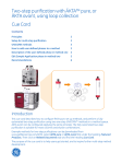
See the description below and the illustration for how to
connect the modules.
Flow path connections:
No.
1
2
3
4
5
6
7
8
9
1
From
1
V9-C or V9-Cs
1
V9-C or V9-Cs
V9-C
V9-V(1)
V9-V(1)
V9-V(2)
V9-V(1)
V9-V(2)
V9-V(2)
port
1A
1B
Out
3
2
4
4
2
1
To
Column 1
Column 1
V9-V(1)
V9-V(2)
Column 2
Column 2
UV monitor
UV monitor
V9-O
port
inlet
outlet
1
3
inlet
outlet
inlet
outlet
inlet
V9-Cs only applicable for ÄKTA pure as V9-C is always present in ÄKTA avant.
Note: To distinguish between the two versatile valves, set
the node ID for Versatile valve V9-V(1) to 20 and the node
ID for Versatile valve V9-V(2) to 21. See ÄKTA pure User
Manual and ÄKTA avant User Manual for details.
Important
Read ÄKTA pure Operating Instructions or
ÄKTA avant Operating Instructions before
using the instrument.
2
1
5
2
7
V9-Cs
6
1
3
1
U9-L
2
4
V9-V (1)
2
4
3
3
4
8
V9-V (2)
9
V9-Os
The illustration shows the flow path allowing tandem two-step
1
purification using the UV monitor U9-L installed on ÄKTA pure .
1
Only applicable for ÄKTA pure since U9-M is always present in ÄKTA avant.
Note: Only some optional modules and tubing are
included in this picture.
Note: Select tubing id that matches the current tubing kit
used. Minimize the tubing length for optimal results.
Note: If the UV monitor U9-M is used instead of U9-L,
position the two versatile valves as close to the UV flow
cell as possible to minimize the delay volumes in the
instrument.
Tandem two-step purification using ÄKTA pure or ÄKTA avant, 29090806 AB
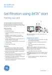
Valve positions and functionality
The two versatiles valves, UV monitor and second column
constitute one unit with a flow path configuration that
is dependent on the valve positions used in the versatile
valves. Below are example flow path configuration
shown for ÄKTA pure.
Four different flow path configurations are used:
2. Purification step one: loading and
wash of column one
1. Priming of the system
Both columns and UV monitor are offline.
First column and UV monitor are inline.
Second column is offline.
UV monitor measures after the first column.
V9-C
V9-V (1)
1
V9-C
V9-V (2)
V9-V (1)
1
1
U9-L
2
2
2
4
2
4
4
4
3
3
3
3
V9-V (2)
1
U9-L
Valve positions
• V9-C: By-pass
• V9-V (1): 1 - 3
• V9-V (2): 1 - 3
Valve positions
• V9-C: 1
• V9-V (1): 1 - 4 & 2 - 3
• V9-V (2): 1 - 2 & 3 - 4
3. Purification step one: elution and
loading column two
4. Purification step two: wash and
elution of column two
Both columns and UV monitor are inline.
UV monitor measures after the first column.
Second column and UV monitor are inline.
First column is offline.
UV monitor measures after the second column.
V9-C
V9-V (1)
1
V9-V (2)
2
4
V9-V (1)
1
V9-V (2)
1
U9-L
2
2
4
3
Valve positions
• V9-C: 1
• V9-V (1): 1 - 4 & 2 - 3
• V9-V (2): 1 - 4 & 2 - 3
V9-C
1
U9-L
4
3
2
4
3
3
Valve positions
• V9-C: By-pass
• V9-V (1): 1 - 2 & 3 - 4
• V9-V (2): 1 - 2 & 3 - 4
Tandem two-step purification using ÄKTA pure or ÄKTA avant, 29090806 AB
3
UNICORN methods
Method one
Method two
Objective
Objective
Perform the first purification step. After sample loading
and wash, the eluted peak of interest is directed onto the
second column.
Perform the second purification step on column two,
with the protein fraction loaded on column two in the
first purification step, and collect fractions of the eluted
peaks.
Description
The sample is loaded onto column one and during
elution and when the watch condition for peak start is
fullfilled, valves turn into position Loading column two.
The UV monitor is located after column one. When the
peak has passed the UV monitor, the flow is directed onto
the second column.
Note: The example below allows one detected peak to be
loaded onto the second column.
Description
The sample is eluted from column two and the column
is equilibrated. The Elution and Equilibration phases
are preceded by user defined phases to set the valve
configuration to Wash & Elution step two position.
The UV monitor is located after the second column in
order to monitor the peak elution.
Note: The second column has to be equilibrated and
ready for use prior to the method start.
How to add user defined phases to a method
Create and edit phases
The UNICORN Method Editor software is used when
creating and editing phases. Follow the steps below to
create a user defined phase:
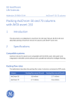
The illustration below shows an example of a UNICORN method
that can be used for purification step one.
• Rename a global phase
• Add new text instructions
• A user defined phase can be saved in the Phase
Library under Global Phases or Personal Phases for
future use.
For easy identification, the modified phases used in this
application were renamed starting with a # symbol.
The :T symbol is a software generated indication for a
text edited phase.
Note: For a comprehensive guide to creating methods
that can be run on ÄKTA pure and ÄKTA avant systems,
refer to the UNICORN Method Manual.
For an explanation of the used methods, see next pages.
4
Tandem two-step purification using ÄKTA pure or ÄKTA avant, 29090806 AB
Structure and content of a method used for
purification step one
User defined phases to set the valve configuration to the
Wash and Elution steps.
V9-C
V9-V (1)
1
V9-V (2)
1
U9-L
2
4
2
4
3
3
Optional user defined phase can be used to set new
pressure control parameters to facilitate crude sample
loading and minimize oscillating behaviour of the flow
rate.
Tip: Lower the value of I and P to get a slower, smoother
response in flow rate adjustment. See an example below.
In this Pressure control parameters example, P = 2.0,
I = 10.0 and target value for pressure control = 75 {%}.
The values for P and I can vary greatly. The default
values are P = 8.0, I = 40.0 and target value for pressure
control = 90 {%}.
Tandem two-step purification using ÄKTA pure or ÄKTA avant, 29090806 AB
5
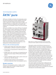
Structure and content of a method used for
purification step one (continued)
User defined phase for defining:
• Watch instructions during the elution, used for peak
detection.
• Valve configuration to direct/transfer detected peak to
the second column (the valve configuration is defined
and initiated).
V9-C
V9-V (1)
1
V9-V (2)
1
U9-L
2
4
3
Delay volume
from UV
monitor to the
second column.
2
4
3
Watch instruction that detects peak
end terminates the elution phase
when peak end is detected.
Note: To calculate delay volumes, the volume of each
component can be found in ÄKTA pure User Manual and
ÄKTA avant User Manual. The volume of tubing can be
calculated using the formula:
Volume (ml) = Length (mm) × (i.d. (mm))2 × π /4.
• Elution phase.
• Previously set watch commands will be active during
the elution.
• The Watch instruction for peak end triggers the end of
the elution phase.
Renamed Miscellaneous phase introducing a delay.
The delay is necessary because the last part of the
peak has to leave the UV monitor and enter the second
column before method one ends.
6
Tandem two-step purification using ÄKTA pure or ÄKTA avant, 29090806 AB
Structure and content of a method used for
purification step two
Instructions to set valve configuration to Wash & Elution
position. Illustration shows ÄKTA pure as an example.
V9-C
V9-V (1)
1
V9-V (2)
1
U9-L
2
4
2
4
3
3
Recommendations
Peak detection
Column CIP and Equilibration
Set watch limits so that end peak is not triggered by start
peak values. For example, set start peak to greater than
100 mAU and end peak to less than 100 mAU.
Another way is to use the instruction Peak_start_max
before the peak end instruction (see UNICORN Method
Manual).
The peak volume should be larger than the delay volume
between the UV monitor and the second column. The
delay volume is typically 0.1 to 0.3 ml.
• It is recommended that equilibration of column two
is performed as a first method in the method queue
executed prior to starting method one. This ensures
that step two is ready to start with the elution step.
Column selection
• For loading larger sample volumes, a Sample pump or
the System pump in combination with a Mixer valve, in
ÄKTA pure, can be used.
• If a Sample pump is available, the addition of a sample
inlet makes it possible to load the whole sample using
air sensors, and also to load multiple samples.
• For full control of protein elution and simplicity,
a second UV monitor can be added, allowing for
simultaneous monitoring of both columns.
Take proper care in selecting the column for the second
step, especially with respect to maximum load volume
but also with respect to pressure limits when both
columns are in the flow path.
Good combinations are:
Purification step one
Purification step two
1 ml HiTrap™
2 × 5 ml HiTrap Desalting
columns in series
1 ml HiTrap
Gel filtration/Size exclusion
column, i.d. 16 mm
5 ml HiTrap
HiPrep™ Desalting
5 ml HiTrap
Gel filtration/Size exclusion
column, i.d. 26 mm
•CIP of column one can preferably be a dedicated
method in the method queue executed as the last
method.
Other options
Download
Example methods for two-step purifications for ÄKTA
pure (either equipped with Sample pump or not) and
ÄKTA avant, can be downloaded from
www.gelifesciences.com/AKTA, select ÄKTA pure or ÄKTA
avant link under the heading Featured Products. Then
click on Related Documents tab and find the heading
Cue Card.
Tandem two-step purification using ÄKTA pure or ÄKTA avant, 29090806 AB
7
Ordering information
For ordering information on columns, valves and tubing,
visit www.gelifesciences.com/AKTApure, or
www.gelifesciences.com/AKTAavant
For local office contact information,
visit www.gelifesciences.com/contact
GE Healthcare Bio-Sciences AB
Björkgatan 30
SE-751 84 Uppsala
Sweden
www.gelifesciences.com/AKTA
GE and GE monogram are trademarks of General Electric
Company.
ÄKTA, HiPrep, HiTrap, and UNICORN are trademarks of General
Electric or one of its subsidiaries.
All other third party trademarks are the propery of their
respective owner.
Any use of UNICORN is subject to GE Healthcare Standard
Software End-User License Agreement for Life Sciences
Software Products. A copy of this Standard Software End-User
License Agreement is available on request.
© 2014-2015 General Electric Company – All rights reserved.
First published Mar. 2014
All goods and services are sold subject to the terms and
conditions of sale of the company within GE Healthcare which
supplies them. A copy of these terms and conditions is available
on request. Contact your local GE Healthcare representative for
the most current information.
GE Healthcare Europe GmbH
Munzinger Strasse 5, D-79111 Freiburg, Germany
GE Healthcare UK Limited
Amersham Place, Little Chalfont, Buckinghamshire, HP7 9NA,
UK
GE Healthcare Bio-Sciences Corp.
800 Centennial Avenue, P.O. Box 1327, Piscataway,
NJ 08855-1327, USA
GE Healthcare Japan Corporation
Sanken Bldg. 3-25-1, Hyakunincho Shinjuku-ku, Tokyo
169-0073, Japan
29090806 AB 06/2015