1
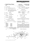
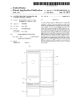
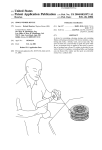
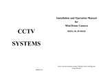
United States Patent [191
[11]
[45]
Himi
Patent Number:
Date of Patent:
[56]
[54] ICE SLICER WITH SYRUP SUPPLY
Apr. 24, 1990
References Cited
MECHANISM
[75] Inventor:
4,919,075
U.S. PATENT DOCUMENTS
Kohei Himi, Kuwana, Japan
3,145,878
3,196,625
8/1964
7/1965
Bert ................................ .. ZZZ/146.5
Nicolaus ...... ..
ZZZ/146.5
Chubu Industries, Inc., Kuwana,
4,049,161 9/1977
4,055,099 10/1977
4,123,918 11/1978
Kohl ............ ..
Mitsubayashi
Kohl et al. .......... ..
4,417,671 11/1983
4,767,068 8/1988
Kawasaki et al.
..... .. 222/56
Ando ................................... .. 83/403
3,211,338 10/1965 Weil et al. .
[73] Assignee:
Japan
[21] Appl. No.: 301,912
[22] Filed:
Primary Examiner—Willard Hoag
Attorney, Agent, or Firm-Fulbright & J aworski
Jan. 25, 1989
[s7]
[30]
ZZZ/146.5
ZZZ/146.6
...... .. 83/403
_. ZZZ/146.6
,
ABSTRACT
In an ice slicer with syrup supply mechanism, a frame is
Foreign Application Priority Data
mounted on a base, a cutter case accommodating a
Feb. 8, 1988 [JP]
Japan ................................ .. 63-15402
rotary blade is mounted to the frame, a slit is formed in
[51]
Int. (11.5 .............................................. .. B05C 5/00
exposed to the slit, a syrup discharge nozzle is provided
[52]
US. Cl. .................................... .. 118/699; 118/15;
at the front of the frame, a connecting tube connects the
discharge nozzle to a syrup container, and an electro
the cutter case, a cutting blade is so mounted as to be
241/101.2; 222/57; 222/135; ZZZ/146.6;
425/ 104; 425/155; 425/306
[58]
Field of Search .................... .. 222/57, 135, 146.6,
.
222/57, 135, 146.6, 146.1, 185; 83/403;
magnetic valve is provided in the connecting tube. The
electromagnetic valve is opened or closed by manipu~
lating an operation switch provided on the frame.
425/104, 306; 118/15, 699; 241/101 R, 25,
101.2
2 Claims, 4 Drawing Sheets
US. Patent
Apr. 24, 1990
Sheet 1 0f 4
FIG.
4,919,075
US. Patent
Apr. 24, 1990
Sheet 2 of4
4,919,075
US. Patent
Apr. 24, 1990
Sheet 3 of4
FIG. 3
4,919,075
1
4,919,075
2
control means of the corresponding set is activated to
open the corresponding electromagnetic valve.
ICE SLICER WITH SYRUP SUPPLY MECHANISM
Still another object of this invention is to provide an
ice slicer which can measure, automatically and quanti
BACKGROUND OF THE INVENTION
tatively, a constant amount of syrup to be sprayed and
spray syrup by the constant amount on ice shavings
1. Field of the Invention
This invention relates to an ice slicer with a mecha
nism adapted to pour or spray syrup on shaved ice or
independently of user's manual operation.
This object can be accomplished by another embodi
ice shavings produced by slicing cubic ice blocks.
2. Description of the Prior Art
In the past, ice slicers have been known and an ice
10
slicer disclosed in US. Pat. No. 4,055,099 is generally
described herein as comprising a frame mounted on a
base, a cutter case mounted to the frame and accommo
dating a rotary blade (rotor) which is driven for rotation
by a motor, and a cutting blade so mounted as to be
exposed to a slit formed in the cutter case.
With the prior art ice slicer, in order to pour or spray
ment of the invention wherein a timer for desirably
setting open time of the electromagnetic valve is pro
vided in a control circuit for the control means. Thus,
the timer is set to a short time setting in order to effect
spray of a small amount of syrup and conversely the
timer is set to a long time setting in order to effect spray
of a large amount of syrup, thereby ensuring‘ quantita
tive adjustment of the constant amount of syrup.
BRIEF DESCRIPTION OF THE DRAWINGS
syrup on ice shavings heaped up in a cup, the syrup is
FIG. 1 is a perspective view illustrating an embodi
dipped out of a separately installed syrup container by 20 ment of an ice slicer according to the invention.
using a ladle and is sprayed or the syrup is discharged
FIG. 2 is a front view, partly exploded, of the em
form a separate syrup container with a cock at the bot
bodiment.
tom by opening the cock and is srayed. Disadvanta
FIG. 3 is a side view, partly exploded, of the embodi
geously, before spraying, the cup with ice shavings
heaped up therein must be pulled out of the ice slicer by 25
hand and moved to a position where the syrup is
poured, resulting in troublesome work.
Further, the user measures the amount of syrup to be
sprayed by eye and the amount of sprayed syrup is
slightly different for every service and can not be con 30
stant.
SUMMARY OF THE INVENTION
This invention contemplates elimination of the above
prior art disadvantages and has for its object to provide
an ice slicer capable of facilitating work of spraying
syrup on ice shavings.
According to the invention, to accomplish the above
ment.
FIG. 4 is an electrical block diagram schematically
illustrating a control circuit in the embodiment.
.DESCRIPTION OF THE PREFERRED
EMBODIMENT
Referring particularly to FIG. 3, a plurality of struts
3 stand uprightly on a base 2 of an ice slicer 1 to support
a frame 4, thereby forming a slicer body. Disposed on
the slicer body is a support wall 16 having a circular
opening in which an inverted-conical portion of a cutter
case 5 ?xedly mounted on the support wall 16 is in
serted. Disposed below the bottom of the cutter case 5
is a motor 18 (FIG. 4) which is mounted on the base 2.
A driving shaft 6 driven by the motor is rotatably sup
object, in an ice slicer of the known type, at least one
ported by the cutter case 5 to project thereinto and a
downward syrup discharge nozzle is provided at the
front of the frame, the discharge nozzle is connected to
rotary blade (rotor) 7 having 3 to 4 blades spaced apart
a syrup container by a connecting tube, and an electro
magnetic valve provided in the connecting tube is con- ~
trolled by a control means. Thus, ice shavings produced
by slicing ice blocks by means of the cutting blade are
received in a cup placed at the front of the frame as in
the case of the prior art ice slicer, the cup is moved
horizontally atthe front of the frame so as to be posi
driving shaft 6 by means of a nut so as to be rotated as
tioned beneath the syrup discharge nozzle, and the elec
tromagnetic valve is opened under the control of the
control means to automatically pour or spray syrup on
ice shavings, whereby ice shavings sprayed with syrup
can be produced without resort to such a troublesome
from the inclined surface of the case 5 is ?xed on the
the shaft 6 rotates.
A front portion of the cutter case 5 is formed with a
slit 8 to which a cutting blade 9 is exposed and a chute
10 attached to a front portion of frame 4 or front cover
surrounds the peripheral edge of the slit 8. A hopper 11
is ?xedly mounted on the rotor 7, a water-proof cover
12 attached to the cutter .case 5 surrounds the hopper
11', and an uppermost head cover 4 with an openable lid
13 is mounted to the slicer body to cover the hopper 11
and water-proof cover 12.
As will be seen from the above, the ice slicer structur
operation of removing the cup from the ice slicer by 55 ally resembles the previously-described known ice
hand as required in the prior art ice slicer.
slicer, with the exception that the width of the frame 4,
Another object of this invention is to provide an ice‘
as viewed from the front, is slightly increased and a
slicer which can facilitate operation of spraying desired
plurality of (four in this embodiment) nozzles 21-1 to
one of a plurality of kinds of syrup on ice shavings.
214 are disposed at the front portion of frame 4 with
This object can be accomplished by an embodiment 60 their tip ends projecting downwards from the front
of the invention wherein a plurality of sets of syrup
cover. These nozzles 21-1 to 21-4 are respectively con
supply means are provided having each a syrup dis
nected to syrup containers, not shown, by tubes 22-1 to
224 through electromagnetic valves 23-1 to 23-4 re
charge nozzle, a connecting-tube for connecting the
nozzle to a syrup container, an electromagnetic valve
spectively located midway between each of the nozzles
provided in the connecting tube, and a control means 65 21-1 to 21-4 and each of the syrup containers. As the
for controlling the electromagnetic valve. Thus, a cup
syrup container, a commercially sold, pneumatically
pressurized syrup container may be used. Individual
with ice shavings is moved to a position beneath a noz
syrup containers may contain different kinds of syrup.
zle for supply of the desired kind of syrup, and the
3
4,919,075
As best see in FIG. 1, a main switch 17 and operation
switches 24-1 to 24-8 for open/close control of electro
4
tion through one of the switches 24-2, 24-4, 24-6 and
24-8 which is once turned on by pushing may be con
trolled in accordance with the time setting and corre
magnetic valves 23 are disposed on a front portion of
the head cover 14 and the operation switches 24 are
sponding one of the electromagnetic valves 23-1 to 23-4 _
electrically interconnected to form a control circuit as
may be opened for corresponding duration of time.
shown in FIG. 4. Of switches 24, the switches 24-1 and
24-2 are used for controlling the electromagnetic valve
23-1, the switches 24-3 and 244 for the electromagnetic
valve 23-2, the switches 24-5 and 24-6 for the electro
magnetic valve 23-3, the switches 24-7 and 24-8 for the
electromagnetic valve 23-4. These are also seen in FIG.
4 a power source 26, a transformer 27, a recti?er 28 and
a timer 29 which can be operated by a knob 25 so as to
thereby making it possible to quantitatively pour syrup
by a constant amount complying with the time setting
of the timer 29.
In the foregoing embodiment, the pneumatically
pressurized syrup container is used and a product of
THE CORNELIUS COMPANY in Minnesota may
preferably be used as this type of syrup container. But
be set to a desired time setting.
products of other companies may be employed and in
place of the pneumatically pressurized container, a con
When slicing ice blocks with the ice slicer 1 con
structed as above, the openable lid 13 of the ice slicer 1
being disposed above the ice slicer with turned upside
is opened, a desired amount of cubic ice blocks are
charged into the cutter case 5 by way of the hopper 11,
the lid 13 is closed and the main switch 17 is transferred
tainer having an outlet at the bottom may be used by
down.
Further, the cutter case 5 with inverted-conical por
tion has been described for illustration purpose only and
from neutral contact 31 to motor contact 32 to drive the
a cutter case of other types may also be used.
motor 18 for ice slicing. With the motor 18 driven, the
driving shaft 6 and the rotor 7 connected thereto are
rotated to thereby cause the cubic ice blocks in the rotor
7 to rotate at high speeds along the inner surface of the
Although a particular preferred embodiment of the
invention has been disclosed in detail for illustrative
purposes, it will be recognized that variations or modifi
cations of the disclosed apparatus, including the rear
rangement of parts, lie within the scope of the present
invention.
What is claimed is:
cutter case 5.
Under the high-speed rotation, the cubic ice blocks
are sliced or shaved by the cutting blade 9 having the
cutting edge exposed to the slit 8 formed in the front
portion of the ice slicer 1, and ice shavings are dis
charged through the discharge chute 10 and heaped up
in a cup 35 which is located beneath the chute 10 at the
front of the ice slicer.
1. An ice slicer with syrup supply mechanism com
prising:
a frame mounted on a base;
a cutter case mounted to said frame and accommodat
ing a rotor driven for rotation by a motor;
Then, the cup 35 with ice shavings heaped up therein
is displaced to a position underlying desired one of the
a cutting blade so mounted as to be exposed to a slit
nozzles 21-1 to 21-4 which are arrayed on the lefthand
side of the front of the ice slicer as best seen in FIG. 2
at least one downward syrup discharge nozzle pro
and the main switch 17 is transferred from motor
contact 32 to control contact 30. Subsequently, one of
the syrup supply operation switches 24-1, 24-3, 24-5 and
formed in said cutter case;
vided at the front of said frame;
a connecting tube for connecting said discharge noz
zle to a syrup container installed separately from
nozzle, is turned on'by pushing so that corresponding
said ice slicer;
an electromagnetic valve provided in said connecting
tube; and
one of the electromagnetic valves 23-1 to 23-4 can be
control means, provided inside said frame, for con
24-7, corresponding to or associated with the desired
energized to open. In response to opening of the elec
tromagnetic valve 23, syrup contained in a syrup con
tainer connected with this electromagnetic valve 23 45
runs through one of the tubes 22-1 to 22-4 which is
associated with the valve 23 of interest and is dis
charged through the desired nozzle so as to be poured
trolling said electromagnetic valve, said control
means including ?rst and second electrical
switches connected in parallel with each other and
connected to said electromagnetic valve, said ?rst
switch being a manual off on switch providing a
variable discharge amount mode of operation and
said second switch being controlled by a settable
or sprayed on the heaped-up ice shavings. Thereafter,
the pushed switch 24 is turned off by releasing the fin
ger from this switch to stop the syrup from discharging.
timer providing a constant discharge amount mode
Accordingly, there is no need of manipulating a lad
dle to spray syrup on ice shavings heaped up in the cup
35 held in hand and all the user has to do is displace the
2. An ice slicer according to claim 1 wherein a plural
ity of sets of syrup supply means are provided having
each a syrup discharge nozzle, a connecting tube for
of operation.
position of the cup 35 slightly, transfer the main switch 55 connecting said discharge nozzle to a syrup container,
17 and operate one of the operation switches 24-1, 24-3,
an electromagnetic valve provided in said connecting
‘
tube, and control means for controlling said electro
It will be noted that the above operation is described
magnetic valve, said control means for each set of syrup
by referring to a variable discharge-amount mode using
supply means including ?rst and second electrical
the operation switches 24-1, 24-3, 24-5 and 24-7 wherein 60 switches connected in parallel with each other and
on-time of one of these operation switches can be con
connected to said electromagnetic valve, said ?rst
trolled or changed manually to adjust the discharge
switch being a manual off-on switch providing a vari
amount. In another mode of quantitatively constant
able discharge amount mode of operation and said sec
discharge amount using the operation switches 24-2,
ond switch being controlled by a settable timer provid
24-4, 24-6 and 24-8,‘ the timer 29 is set to a desired time 65 ing a constant discharge amount mode of operation.
*
*
*
*
*
setting by operating the. knob 25 so that current conduc
24-5 and 24-7.