1
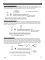
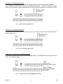
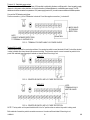
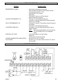
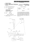
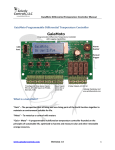
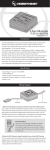
HAM841K
ALARM CONTROL PANEL FOR COMMERCIAL
AND RESIDENTIAL SECURITY SYSTEMS
USER MANUAL
USER MANUAL HAM841K
ALARM CONTROL PANEL FOR COMMERCIAL AND RESIDENTIAL SECURITY SYSTEMS
INTRODUCTION
The HAM841K (HA-841K) is a complete alarm control panel designed for commercial and residential security systems and
equipped with the latest electronic control technology. It has the highest level of quality and reliability. The exceptional
specifications incorporate many features that are generally only found in advanced professional systems. The HAM841K
(HA-841K) accepts active and passive sensors/detectors to form a versatile protection system.
ADJUSTS DURATION OF 24
HOUR PANIC/FIRE SIREN
ALARM STATUS
INDICATOR
TEST/OPERATE
SELECTOR
POWER ON-OFF
KEY SWITCH
CABINET LOCK
24-HOUR
PANIC BUTTON
ADJUSTS DURATION OF ADJUSTS DURATION OF
BURGLARY SIREN
ENTRY DELAY
MAIN POWER
ON-OFF SWITCH
CONNECTION
TERMINALS
(SEE DESCRIPTION FOR
DETAILED INFORMATION )
BATTERY COMPARTMENT
NOTES FOR INSTALLING TECHNICIAN
WIRE FEEDTHROUGH HOLES
The HAM841K panel is extremely reliable. Use the check list at the back of the manual in case of trouble. Recheck all the
wiring if the list does not help.
INTERNAL CONTROLS
1.
Main Power Switch :
Enables the user to disconnect or connect the power.
2.
Test/Operate Switch :
This switch allows the installer to test the panel without activating the siren or the relays. In the test position the siren
is replaced by the internal buzzer that beeps "2 seconds on 1/4 second off" during the alarm period. This switch
should be placed in the" operate" position for the siren and relays to operate normally.
3.
Duration Siren 24h / Panic Function / Fire :
Determines the length of time the siren will sound before resetting when it is triggered by the 24hr instant-alarm
circuit. This circuit is adjustable from 30 sec. to 3 min.
4.
Siren Duration / Burglary :
Determines the length of time the siren will sound before resetting when it is triggered by the N.C. (Normally Closed)
instant-alarm circuit or by the N.C. or N.O. (Normally Open) delayed-alarm circuits. The activation period is
adjustable from 30 sec. to 3 min.
5.
Entry Delay :
Determines the duration of the delay : from 0.5sec. to 90sec.
6.
Key Switch :
Switches alarm circuits on/off and does not affect the 24hr instant-alarm circuit.
HAM841K
2
GB
7.
Panic Button :
Connected internally to the 24hr instant-alarm circuit. Pressing this button will activate the siren, regardless the
position of the key switch.
LED INDICATIONS
• Exit / Armed (GREEN) :
This LED indicates the status of the alarm. The exit period (60 sec.) begins when the key switch is put in the "on"position. The LED will flash and will then remain lit continuously when the exit period ends. The Exit/Armed LED will be
extinguished if either the instant-alarm circuits or delayed-alarm circuits are activated (RED). The function of this LED is
duplicated on terminal 4 so that remote indication can be used.
• Instant-alarm Circuit LED (RED) :
This LED will light whenever either of the instant-alarm circuits (24hr or N.C.) is operated while the key switch is in the
"on"-position.
• Delayed-alarm Circuit LED (RED) :
This LED will light whenever either of the delayed-alarm circuits (N.O. or N.C.) is operated while the key switch is in the
"on"-position.
• Alarm Memory LED (GREEN) :
This LED will light when the alarm is triggered and will remain lit until the main power switch is turned off or until the key
switch is turned "off-on-off". The alarm was triggered in your absence if this LED is lit.
• Battery-Low LED (GREEN) :
This LED will flash once every 2 sec when the battery voltage drops below 11.5 Volts.
• AC Power LED (AMBER) :
This LED indicates that power is supplied to the panel (main power switch is in the "on"-position). It should remain lit
continuously. The backup battery will supply the necessary power if the main power switch is in the "on"-position and
this LED is not lit. Restore the primary power source as soon as possible.
INTERNAL WARNING TONES
Exit Delay Period*
Entry Delay Period
Battery-Low Indication
Alarm Test Mode
Tamper Alarm
Horn Speaker Wire Is Cut
- Short "BEEP" at 1/2 second intervals
- 2-second "BEEP" at 1/4 second intervals
- Short "BEEP" at 2-second intervals
- 2-second "BEEP" at 1/4 second intervals
- 2-second "BEEP" at 1/4 second intervals (Short 20-21 to deactivate the alarm)
- 2-second "BEEP" at 1/4 second intervals (1K resistor between 11-12 to deactivate the alarm)
* if terminals 11 & 12 are connected by a 1KΩ resistor
HAM841K
3
GB
CONNECTIONS
Terminal 1 & 2 : 24 hr instant-alarm circuit
This circuit is monitored round the clock and is unaffected by the alarm key switch. This is a normally open circuit. It can be
used for fire and smoke detectors, panic switches and tamper circuits. Note : these two terminals must remain open, i.e. no
connection should exist between 1 & 2 when all switches and sensors are in their normal reset positions.
PANIC
SMOKE/FIRE
SENSORS
FIG.1 : 24HR INSTANT-ALARM CIRCUIT
NOTE :
N.O. CONTACTS SHOULD
BE WIRED IN PARALLEL
Terminal 2 & 3 : N.C. Instant-alarm Circuit
This circuit is controlled by the alarm on/off key switch. Use it to connect any area that requires protection without using a
delay between detection and the sounding of the siren - motion sensors, window switches, window foil tapes etc. can be
connected here. The contacts of these sensors should be shorted when in the normal reset condition and they should be
arranged in a series loop (see figure 2).
ALARM SENSOR
CONTACTS
NOTE :
N.C. CONTACTS SHOULD
BE WIRED IN SERIES
FIG. 2 : N.C. INSTANT-ALARM CIRCUIT
Terminal 4 : Alarm status indication
Terminal 4 allows the connection of a low-current LED with the same function as the Exit/Alarm LED. It can be used on
external key switches in order to provide an indication of the alarm status. The cathode terminal (normally indicated by a
small flat on the plastic body adjacent to the lead. The cathode is the shorter of the two leads of this LED) is connected to
terminal 4 and the anode terminal is connected to the positive power connection (terminal 21). This circuit does not require
a resistor as the control panel is equipped with an internal resistor. Reverse the connections and try again if the LED does
not work. LEDs are available from electronic supply stores.
SMALL FLAT
CATHODE
ANODE
1K INTERNAL
CATHODE
LED
ANODE
CATHODE
FIG. 3 : REMOTE ALARM STATUS INDICATOR
HAM841K
4
GB
Terminal 5 & 6 : N.C. Delayed-alarm Circuit
This circuit is controlled by the alarm on/off key switch. It should be used for any area requiring a delay between the
moment of detection and the activation of the siren. These contacts should be N.C., i.e. terminals 5 & 6 should be shorted
under normal circumstances. The delay is adjustable from 0.5 sec to 90 seconds by using the control marked "entry delay".
ALARM SENSOR
CONTACTS
FIG. 4 : N.C. DELAYED-ALARM CIRCUIT
Terminal 6 & 7 : N.O. Delayed -alarm Circuit
This circuit has the same function as 5 & 6 but it is a N.O. circuit : the contact must be open under normal circumstances.
Ideal for pressure mats.
ALARM SENSOR
CONTACTS
FIG. 5 : N.O. DELAYED-ALARM CIRCUIT
Terminal 9 & 10 : Connections for Internal Battery Charger
These terminals should be linked to connect the internal battery charger to a rechargeable battery (we strongly advise you
to use a 12V rechargeable battery).
NOTE :
LINK 9 & 10 for
RECHARGEABLE BATTERY
DO NOT CONNECT
WHEN USING STANDARD
BATTERIES
FIG. 6 : CONNECTIONS FOR RECHARGEABLE BATTERY
HAM841K
5
GB
Terminal 11 & 12 : Siren speaker output
These terminals provide a high-level siren signal that drives up to two 8 ohm (horn) speakers. Shorting these terminals or
using more than 2 speakers will result in serious internal damage. The control panel has an internal alarm that will
sense when the speaker wires are cut. Consequently, the 1K ohm resistor installed across the terminals should be left in
place if no speaker is connected. Remove this resistor if a speaker is connected.
NOTE :
LINK 11 & 12
WITH A 1K OHM RESISTOR IF
NO SPEAKERS ARE
CONNECTED
8 OHM
SPEAKERS
(MAX. 2 !!)
FIG. 7 : CONNECTION FOR SPEAKER SIREN
Terminal 13 & 14 : Alarm relay contact
This is a single contact that shorts when the alarm sounds and deactivates when the alarm resets. It can be used to switch
strobes and self-contained sirens, etc. Power is taken from terminal 10 and switched through the relay contact.
Note :
A max of 1Amp is available at terminal 10. Use an external supply when more current is needed. The max. current is 3
Amps (see figure 9).
STROBE / SIREN, etc.
FIG. 8 : ALARM RELAY CONNECTION
EXTERNAL
SUPPLY
MAX. 3 AMPS
FIG. 9 : RELAY CONNECTION FOR HIGHER CURRENT/VOLTAGE
HAM841K
6
GB
Terminal 15 & 16 : Alarm memory relay contacts
These contacts operate at the same time as the alarm relay contact. However, the contacts remain activated until the
power is turned off or the alarm key switch is turned "off-on-off" (same as the Alarm Memory LED). It can be used to
provide an external indication of the fact that the alarm has been triggered (alarm memory). Again, the max. current for the
contact is 3 Amps. Power is connected in the same way as with terminals 13 and 14.
LIGHT
1AMP MAX.
FIG. 10 : ALARM MEMORY RELAY CONNECTION - REMOTE ALARM MEMORY INDICATION
Terminal 17 & 18 : Power input
The polarity of these terminals is irrelevant if you have a 16V AC panel. Simply connect the two wires from the plug pack to
these terminals. If you have a 12V DC panel, you should be careful to connect the power supply using the correct polarity :
terminal 17 is positive (+), terminal 18 is negative (-)*.
IMPORTANT : The standard Velleman version of this product is supplied with a 13.8VDC power supply !!!
If you do not know which type of panel you have, you should check the area behind the terminals under the main circuit
board. If you have a 16V AC panel, you will find a small auxiliary circuit board of approx. 50 x 25mm in this area.
* Note : the DC input voltage should be 13.8V (or 14V) to ensure correct charging of the battery.
+
-
16VAC
OR
+VE
-VE
13.8VDC
FIG. 11 : POWER INPUT CONNECTION FOR AC OR DC POWER SUPPLY
HAM841K
7
GB
Terminal 19 : Switchable power output
This terminal provides a 12V DC output of max. 0.5 Amps that is switched by the alarm on/off key switch. It can be used to supply
ultrasonic or microwave motion detectors, etc. Avoid connection of infrared detectors to a switchable power supply. The PIR
detectors should be connected to a permanent 12V power supply (terminal 21) in order to ensure stable and reliable operation.
Connect the PIR detectors as follows :
Positive connection (+) of the PIR detector to terminal 21 and the negative connection (-) to terminal 6.
MICRO WAVE /
ULTRASONIC
DETECTORS
NOTE :
CONNECT INFRARED DETECTORS
TO TERMINAL 21 INSTEAD OF 19
+ 500mA MAX
FIG. 12 : TERMINAL FOR SWITCHABLE 12V POWER SOURCE
Terminal 20, 21 and 8
These terminals are used for remote key switches. If no remote key switch is used, terminals 20 and 21 should be shorted
in order to disable the internal alarm that senses wire cutting. There are two ways to connect a remote key switch to the
panel. Both methods (see diagram) will activate an internal alarm if the wiring is cut.
METHOD 1
FIG. 13 : REMOTE KEYSWITCH WITH CUT WIRE PROTECTION
METHOD 2
NOTE :
TERMINALS 20 & 21
MUST BE LINKED
FIG. 14 : REMOTE KEYSWITCH WITH CUT WIRE PROTECTION
NOTE : The key switch on the panel should be left in the "on"-position when an external key switch is being used.
Both methods of remote key switch connection are secure : the alarm will be activated if the wiring is cut.
HAM841K
8
GB
PROBLEM CHECKLIST
PROBLEM
POSSIBLE CAUSE
BEEPER KEEPS SOUNDING
-
INSTANT LED PERMANENTLY ON
DELAY LED PERMANENTLY ON
-
LOW BATTERY INDICATION
-
SIREN WILL NOT SOUND
INSTANT-ALARM/DELAYED-ALARM CIRCUITS
DO NOT WORK
-
Verify whether the speakers are connected
When no speakers are used, the 1Kohm resistor should be
connected across terminals 11 & 12
Terminals 20 & 21 are not linked
Weak battery
"Test/Operate"" switch is in the "Test"-position
Beeper sounds during exit period
Terminals 1 & 2 are shorted (should be open)
Terminals 2 & 3 are open (terminals 2 & 3 should be shorted if
the alarm is not activated)
Terminals 5 & 6 are open. They should be shorted if the alarm is
not activated.
Terminals 6 & 7 are shorted (should be open)
Terminals 9 & 10 are not linked (should be linked in order to
charge the battery)
NOTE : When using standard batteries, do not link terminals
9 & 10 to the battery (use a 12V rechargeable
battery)
"Test/Operate" switch is in the "test"-position
Wiring is cut
1Kohm resistor has not been removed
Key switch is not in the "on"-position
Incorrect wiring : N.O. switch is wired in series or N.C. switch is
wired in parallel
CONNECTION TERMINALS
FIRE/SMOKE
SENSOR
N.C.
SWITCHES
24 HOUR
N.O.
INSTANT
N.C.
INSTANT
N.C.
SWITCHES
REMOTE
ALARM
STATUS
N.O.
SWITCHES
N.C.
DELAY
N.O.
DELAY
RECHARGEABLE BATTERY : CONNECTED
NORMAL BATTERY - OPEN
BATTERY
CHARGER
+
INTELLIGENT
SIREN DRIVER
OUTPUT
8 Ω HORN
SPEAKER
(MAX . TWO)
OUTPUT FOR ALARM
OUTPUT FOR ALARM
RELAY CONTACT (3AMP MEMORY RELAY CONTACT
MAX.)
(3AMP MAX.)
12VDC (+)
ON
OFF
REMOTE KEY SWITCH
WITH CUT WIRE PROTECTION
POWER IN : SEE TEXT
HAM841K
9
GB