1
ii
PSZ 19:16 (Pind. 1/07)
UNIVERSITI TEKNOLOGI MALAYSIA
DECLARATION OF THESIS / UNDERGRADUATE PROJECT PAPER AND COPYRIGHT
Author’s full name : AMY WONG AI LING
Date of birth
:
19th MARCH 1987
DOUBLE
SECURITY SYSTEM USED M TOUCHPAD AND RFID
: DOUBLE SECURITY SYSTEM USED M TOUCHPAD AND RFID
Title
Academic Session :
2010/2011
I declare that this thesis is classified as :
AMY WONG AI LING
√
CONFIDENTIAL
(Contains confidential information under the Official Secret
Act 1972)*
RESTRICTED
(Contains restricted information as specified by the
organization where research was done)*
OPEN ACCESS
I agree that my thesis to be published as online open access
This thesis is submitted in part fulfillment
(full text)
of Universiti
the requirements
the awarding
of Degree
I acknowledged that
Teknologi for
Malaysia
reserves the
right asof
follows:
Bachelor
of of
Engineering
(Electrical
- Electronics)
1. The thesis is the
property
Universiti Teknologi
Malaysia.
2. The Library of Universiti Teknologi Malaysia has the right to make copies for the purpose
of research only.
3. The Library has the right to make copies of the thesis for academic exchange.
Certified by :
Faculty of Electrical Engineering
SIGNATURE
Universiti Teknologi Malaysia
SIGNATURE OF SUPERVISOR
870319-52-6442
DR MUHAMMAD NASIR BIN IBRAHIM
(NEW IC NO. /PASSPORT NO.)
Date : 19
NOTES :
*
th
MAY 2011
NAME OF SUPERVISOR
MAY 2011
Date : 19
th
MAY 2011
If the thesis is CONFIDENTAL or RESTRICTED, please attach with the letter from
the organization with period and reasons for confidentiality or restriction.
iii
“I hereby declared that have read this thesis and in my opinion this report has fulfills the
scope and quality for the award of Degree of Bachelor of Engineering (ElectricalElectronics).”
Signature
: ……………………
Name of Supervisor
: DR MUHAMMAD NASIR BIN IBRAHIM
Date
: 19th MAY 2010
iv
DOUBLE SECURITY SYSTEM USED M TOUCHPAD AND RFID
AMY WONG AI LING
This thesis is submitted in part fulfillment
of the requirements for the awarding of Degree of
Bachelor of Engineering (Electrical - Electronics)
Faculty of Electrical Engineering
Universiti Teknologi Malaysia
MAY 2011
ii
DECLARATION
“It is hereby declared that all the materials in this thesis are the effort of my own work
and idea except for works that have been cited clearly in the references. The thesis has
not been accepted for any degree and is not concurrently submitted in candidature of any
degree.”
Signature
: ……………………
Name of Author
: AMY WONG AI LING
Date
: 19th MAY 2011
iii
Dedicated and thankful to my beloved family, lecturers and friends for their advice,
encouragement and support
iv
ACKNOWLEDGEMENT
First and foremost, I would like to express my deepest gratitude to my
supervisor, Dr Muhammad Nasir bin Ibrahim for the guidance, encouragement,
enthusiasm, patient, invaluable support and motivation throughout the progress of this
project. This project would not be success without continue support from him. In
completing this project within whole year, I had learned a lot, not only in how to
complete the project but in many other part of life also.
Second, I would like to drop my sincere appreciation to thank all my friends who
have directly or indirectly do me a favor in completing this project. Their useful and
worth opinions, ideas, advice, encourage and support are accompanying me in
completing this project.
Last but not least, to all my beloved family members who were always, stand by
my side to encourage and support me during this entire project. Sincere appreciation
goes to them who has been so supportive either morally or financially.
Lastly, I really appreciate to have this chance to finish this topic of project. It
lets me gain an experience and a lot of knowledge which I never learn before and it is
valuable for me in future career.
v
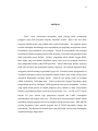
ABSTRACT
Security elements are an important aspect to prevent the unauthorized or
unknown users to access the house. Traditionally, the conventional lock and key is a
simple method for security purpose. But the increasing number of unauthorized entry
cases over this few years, cause manufacturers to provide one level security. This
project provides two levels of securities which are entering the 6 digit numerical number
password and identification number scanning through RFID.
Correct numerical
password is required in order to proceed to the next level of security which is
identification process.
The system cannot be access without the correct numerical
password and identification number of RFID passive tag. M Touchpad is used to
replace the mechanical button keypad in this project.
The main advantage of m
Touchpad (first level of security) is the numerical number on pad can be arranged
according to the preference of designer. Besides, the cost for m Touchpad is low and it
is longer lasting. The capacitive sensing concept used to operate the m Touchpad. RFID
is used for identification process. Processor chosen in this project is a microcontroller
which can provide efficient interactions between hardware and software. The special
features of PIC16F727 such as powerful I/O port, capacitive sensing channel and UART
ability add some value to the system. The cost and power requirement is low compared
to the other microcontroller or microprocessor family. MPLAB IDE software is used to
write program and IC PROG is used as burning tools.
Based on the overall results
obtained, the proposed system is verified to be functioning correctly.
vi
ABSTRAK
Unsur- unsur keselamatan merupakan aspek penting untuk menghalang
pengguna yang tidak diketahui daripada memasuki rumah.
Kunci dan alat untuk
mengunci adalah kaedah yang mudah untuk tujuan keselamatan. Kes pemasuk haram
semakin meningkat kebelakangan ini menyebabkan para pengilang mengeluarkan sistem
keselamatan yang melibatkan satu peringkat. Projek ini menyediakan dua peringkat
keselamatan dimana peringkat pertama ialah menekan 6 kata laluan dan peringkat kedua
ialah pengenalan proses berlaku. Nombor pengesahan boleh diimbas dengan RFID.
Kata laluan yang betul adalah diperlukan supaya boleh terus ke peringkat seterusnya
iaitu pengesahan nombor pada RFID pasif kad. Sistem tidak dapat diakses sekiranya
tidak ada kata laluan dan pengenalan nombor yang betul. M touchpad digunakan untuk
mengganti mekanik butang keypad dalam projek ini. Kebaikan utama menggunakan m
Touchpad (peringkat pertama keselamatan) adalah nombor bagi setiap butang boleh
ditentukan berdasarkan kesukaan pereka.
Selain itu, kos buatan untuk m Touchpad
adalah rendah dan lebih tahan lama. Konsep pengesanan kapasitif digunakan untuk
pengendalian operasi m Tocuhpad. RFID digunakan untuk proses pengenalan. Prosesor
yang dipilih dalam projek ini adalah pengawal micro dimana ia dapat menyediakan
interaksi yang berkesan antara peranti keras dan perisian. Ciri – ciri PIC 16F727 seperti
banyak I/O port, saluran bagi pengesanan kapasitif dan UART kemampuan
menambahkan nilai kepada sistem ini. Kos dan kuasa yang diperlukan adalah rendah
berbanding dengan pengawal micro lain ataupun keluarga prosesor micro. MPLAB IDE
perisian digunakan untuk menulis program dan IC PROG digunakan sebagai alat
pembakaran. Berdasarkan keseluruhan hasil yang diperolehi, sistem yang dicadangkan
disahkan berfungsi dengan betul.
vii
TABLE OF CONTENTS
CHAPTER
1
TITLE
PAGE
DECLARATION
ii
DEDICATION
iii
ACKNOWLEDGEMENT
iv
ABSTRACT
v
ABSTRAK
vi
TABLE OF CONTENTS
vii
LIST OF TABLES
xi
LIST OF FIGURES
xii
LIST OF APPENDICES
xiii
INTRODUCTION
1
1.1 Background
1
1.2 Product Overview
3
1.3 Objectives
4
1.4 Problem Statement
4
1.5 Scope
5
1.5.1 Hardware Development
5
1.5.2 Software Development
5
1.5.3 Interface In Between Hardware and Software
6
1.6 Thesis Contribution
7
1.7 Project Contribution
7
1.8 Project Duration
8
viii
2
LITERATURE REVIEW AND THEORY
9
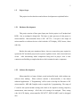
2.1 Introduction
9
2.2 Potential of RFID
10
2.3 Security Analysis
14
2.4 Low Noise Capacitive Sensing Sensor
17
2.5 Conventional Door Security System
19
2.5.1 Key Interlock Conventional
19
2.5.2 Magnetic and Smart Card
22
2.6 Keypad Security System
23
2.7 Microcontroller PIC16F727A
24
2.7.1 Microcontroller PIC16F727 Special Features
25
2.7.2 Pin Diagram
26
2.8 Microchip MPLAB ICD 2
2.8.1 Modular Interface Connections
27
2.8.2 Debug Mode
28
2.8.3 Programmer Mode
30
2.9 M Touchpad (Capacitive Touch Sensor)
31
2.10 RFID
33
2.10.1 Type of RFID Tag and Its Frequencies
3
27
36
METHODOLOGY
38
3.1
38
Process Flow for Double Security System Used M Touchpad
and RFID
3.2
Hardware Design for Double Security System
40
3.2.1 Power Supply Unit
41
3.2.2 Clock Generator Unit
42
3.2.3
43
The Reset Circuit
3.2.4 Interface circuit
44
3.2.4.1 Interface m Touch with PIC16F727
44
3.2.4.2 Interface RFID reader (RFID-IDR-232N)
45
with PIC16F876A
ix
3.2.4.3 Interface LCD (2x 16 Character) with
46
PIC16F727
3.2.5 Output Circuit
3.3
48
3.2.5.1 LED as output for PIC microcontroller
48
3.2.5.2 Buzzer as output for PIC microcontroller
49
3.2.5.3 Relay as output of PIC microcontroller
49
Software Implementation
51
4
RESULTS AND DISCUSSIONS
54
5
CONCLUSION AND RECOMMENDATIONS
59
REFERENCES
62
APPENDIX
63
x
LIST OF TABLES
TABLE NO
TITLE
PAGE
3.1
Indication of RFID wire color
46
3.2
Function Indication of Each Pin on LCD Display
47
xi
LIST OF FIGURES
FIGURE NO
TITLE
PAGE
1.1
Gantt chart for the project
8
2.1
Parking-lot Check-in Process
11
2.2
Parking-lot Check out Process
12
2.3
Behavioral Model of Capacitive Sensing
17
2.4
Operating principle of a simple key interlock mechanism
21
2.5
Pin Diagram of PIC16F727
26
2.6
Pin Numbering for Modular Connector
28
2.7
Connections For Programming
29
2.8
Illustrates the MPLAB ICD 2 ready for debugging.
30
2.9
Diagram of RFID system
34
2.10
Transponder and Reader of RFID system
35
3.1
The methodology and approach of the project
39
3.2
The design concept of the MC68000 ECB
41
3.3
The Voltage Regulator Circuit
42
3.4
The Clock Generator Circuit
43
3.5
The Reset Circuit
43
3.6
The m Touchpad connection
44
3.7
The RFID connection
45
3.8
LCD Display Connection
47
3.9
LED Connection for first level of security
48
3.10
LED Connection for second level of security
48
3.11
Buzzer connection
49
xii
3.12
The Password Entering Circuit
52
3.13
The Identification Scanning Circuit
53
4.1
Project Overview
55
4.2
Project Overview when the password is correct.
56
4.3
Project Overview when the password is wrong.
57
4.4
Schematic Diagram of Double Security System
58
xiii
LIST OF APPENDICE
APPENDIX
A
TITLE
Program Code of Double Security
System Used M Touchpad and RFID
PAGE
64
1
CHAPTER
1
INTRODUCTION
1.1
Background
Nowadays, the security systems are an important aspect to prevent unauthorized
users to access the system security door. Traditional security system involves the use a
conventional locked and keys. The lock and key is a simple method to access control
system.
Over the last several past years, many manufactured have provided an
electronic access control system. The most well-known access control systems are
magnetic card and keypad system. The basic concept for the magnetic card system is the
reader interprets the information encoded on the card and sends it to the controller to
accept the information and unlock the door.
2
However, the system security provide for one level security. Combination two
level securities which are m Touchpad (use capacitive sensing concept) and RFID
passive tag identification through the use of RFID reader will improve the security
system.
Perhaps the most prevalent form of safety security system is by using a
numerical code for authentication; the correct code must be entered in order for the lock
to deactivate.
Usually keypad is used for such locks which relates with entering
password code and there are some feature an audible response to each press. In this
project, m Touchpad is used to replace keypad. M Touch, known also as capacitive
touch sensor, can replace mechanical buttons with capacitive alternative. In addition, it
helps in cost reduction.
M Touch has become more prevalent and in demand for
commercial applications such as mobile devices and mp3 players. Some more, the
numerical number of m Touchpad can be arranged according to the preference of
designer. So, the thieves or criminals find it harder to hack the password and break in.
Break in case can be reduced by using this double security system.
Even the thieves successful hack the password; there still have another level of
security which is RFID passive tag identification. Identification process begins with
bringing the RFID passive tag towards the RFID reader, followed by a scanning process.
By scanning the RFID passive tag on the RFID reader, the identification number will be
obtained. Every passive tag has its own specific identification number. The correct
identification number can cause the scanning process success. The door only can unlock
or opened once the password and identification number is match and correct.
In this era, the system security is an important aspect to prevent the luxurious
asset from unauthorized person. Besides, the most important is it can protect everyone
within house from any dangerous events such as robber, murder, raping and any
unexpected criminal activities. Providing two level securities will improve the control
access system. This system will give a high level of security for user to prevent their
luxurious asset especially for home user being stolen by thieves and protect everyone
from danger.
3
There are few reason why security system is important, reason one is for the
peace of mind.
Security systems employing house monitoring, intercom systems,
CCTV camera surveillance, and control access are the finest methods to guarantee that
peace of mind.
Burglars and thieves can be anywhere. They may be the person that
had bumped into yesterday at the grocery store or someone who is in fact residing in the
owner neighborhood. Installing a security system can help the owner and family rest at
night because the system routinely will be observing over your house, so doesn’t need to
be relied on guard.
Being worry free is really worth a lot to the owner all round
wellness and happiness. Second reason is to protect property, especially if the owner is
from town or taking a holiday. Security systems and burglar alarm system not only
safeguard the owner life but additionally help safeguard the owner property and valuable
possessions. Lastly, if a criminal sees a CCTV camera system or a camera surveillance
system at house, these folks are less likely to try to bust in. CCTV video cameras work
to capture burglars in the act, but also help to avert burglaries from ever happening.
1.2
Product Overview
This project includes two level securities which is capacitive sensing security used m
Touchpad with microcontroller and RFID passive card through RFID reader. The numerical
numbers on m Touchpad can be randomly arranged according to the preference of designers.
Plus, it can reduce cost and more efficient compared with keypad. User must have personal
key to access the first level security. Then read the ID of passive tag by using RFID reader.
There are specific numbers for each passive tag. The user must have the correct ID number
of passive tag to open the door and lock automatically as second level of security.
4
1.3
Project Objective
In general, the objective for this project is to design a double security door. The
main objective is providing two level securities which is password system security used
m Touchpad and ID identification through RFID. Capacitive sensing concept has been
applied for entering the password using m touchpad. Radio frequency identification
(RFID) is an automatic identification method where the data is stored in the RFID tag.
The user must have personal key to access the first level security which is capacitive
sensing system and ID card for second level security to unlock the door.
1.4
Problem Statement
In our country, Malaysia, there are many criminal activities such as stealing,
murdering, raping and breaking cases happen among the citizen, especially at Johor
Bharu. Because of these problems, resident from various sectors need the security
system to ensure safety of their own self, family member, cash money or valuable
things.
In this project, a double security system used m Touch pad (capacitive touch
sensor) and RFID will be introduced which gives enough security protection and is lowcost, user-friendly and lasting. So, it is suit whether a well off or rich family and either
single story or double story house. The market can apply this kind of technologies, so
that every level of resident can protect themselves and safe from dangerous.
5
1.5
Project Scope
This project involves hardware and software development as explained below:
1.5.1 Hardware Development
This project consists of three parts: Input part for this project is m Touchpad and
RFID. One m touchpad is being built. The heart or main processor of this project is
microcontroller. Microcontroller chose is PIC 16F727A. Last part is the output of
microcontroller or indicator devices which includes LCD display, LED, buzzer, alarm
and relay.
Besides the main parts mentioned above, there are some other parts required to
operate the PIC and whole project such as power regulator circuit, clock circuit and reset
circuit.
After determining which components being used in project, next is their
connection and building a complete hardware which contain the entire component.
1.5.2 Software Development
Microcontroller is a lump of plastic, metal and purified sand, which without any
software does nothing.
When software controls a microcontroller, it has almost
unlimited applications. “C Programming” will be used to develop the firmware to PIC
microcontroller. MPLAB Compiler used to compile the C-programming. The range of
C code for this system includes setting code which is for capacitive sensing, frequency
measurement, timer interrupt. All of this is for setting of m touchpad. Then, setting
code for LCD display, microcontroller PIC16F727, RFID (UART) need be designed
also.
6
Program will be started with initialize, then introduce project by displaying
specific sentence on LCD display. Prompt user to enter 6 digit password numbers.
Some operation occurs when the password is correct or wrong. Next stage is prompt
user to scan the RFID passive card, the identification number of the card will be read by
using RFID reader.
The identification number obtained will be transmitted to the
controller. The controller will receive the transmitted number. There are operations
happen when the identification number match or not match with the stall value. Some
identify code is required in this project. It is needed to show what would going to
happen when password is correct or wrong, and whether the identification number
obtained is match with the database information or not. The identification device used
in this project includes LED, buzzer, LCD display and relay.
Besides, DXP Protel 2006 software used to design the schematic diagram for
double security system. The reason used DXP Protel is it is more convenient and
efficient compared with other.
1.5.3 Interface In Between Hardware and Software
Once complete the hardware and software, the next stage is interface in between
hardware and software. The software coding will be burned into PIC programmer and
then from PIC programmer writes into microcontroller PIC. Once the microcontroller
PIC16F727A had been completely programmed, user can test the hardware. If the
output is as desired, this project had successfully completed. Otherwise, troubleshoot
step is required until desired output obtained.
7
1.6
Thesis Organization
Chapter 1 begins with background or brief introduce about the security system,
then is the objective or the purpose of doing this project, continue with the problem
statement which give an idea on doing this title, the scope of project and the last is the
time duration to complete this project. Chapter 2 begins with literature review whereby
some related information or previous works are included.
Chapter 3 discusses the
methodology to achieve the objective of this project. Chapter 4 shows the result and
some discussion which related with the result. The related output figure will be showed
in this chapter. Chapter 5 shows the conclusion; some possible future works will be
suggested.
1.7
Project Contribution
Since the breaking case is keep increasing nowadays, residents from any sectors
have a strong needed on good security system. This project which design a double
security system is a good solution to a wide range of cases happened in Malaysia.
Demand on a home security system which is affordable and reliable for them is high also.
So, this project is worth to proceed and introduce to everyone.
8
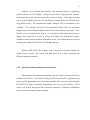
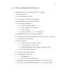
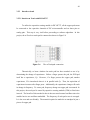
1.8
Project Planning
The project is planned by dividing into several tasks. The duration of each task
has been done and it has been described in Gantt chart below.
Figure 1.1
Follow Up
Gantt chart for the project
Execute
9
CHAPTER
2
LITERATURE REVIEW AND THEORY
2.1
Introduction
The increasing number of unauthorized entry cases over the years, have
prompted many companies to design and manufacture automated door security systems.
Door security systems are designed to protect houses, shops, offices and other buildings
from forced entry and minimized the chances of robbery. Door security systems can be
installed on different types of doors such as metal, wood, plastic, glass and fiberglass.
They are available in different specifications to suit the security requirements of
different types of buildings. Household security systems may consist of a password
enabled electronic locking device, whereas high-end door security systems are often
combined with intruder alarms and security lock to provide enhanced security.
This chapter reviews some of the journal which related with this topic such as
how efficient use RFID technologies nowadays in some application, importance of a
password in security system, how efficient apply memory aids in memorize the multiple
password used in different ways. Besides, this chapter reviews some theories for the
important device used in this project. Some more, some conventional door security
system also had been described here.
10
2.2
Potential of RFID
According to Zeydin Pala and Nihat Inan in journal entitle smart parking
applications using RFID technologies, by using Radio Frequency Identification (RFID)
technology in automation, the transaction costs will be reduced and shortage in stock.
Most of the RFID networks include a wide range of automation technologies. These
technologies consist of RFID readers, RFID writers, RFID barcode scanners, RFID
smart sensors and RFID controllers. The check-ins and check-outs of the car parkinglots will be under control by using RFID readers, labels and barriers. Personnel costs
will be reduced significantly using this technology. It will be possible to see unmanned,
secure, automized parking-lots functioning with RFID technology in the future.
Check-ins and check-outs will be handled in a fast manner without having to stop
the cars with RFID technology, so that traffic jam problem will be avoided during these
processes. This is because drivers no need stop at the circulation points and parking
tickets will be out of usage during check-ins and check-outs.
By using this system,
ticket jamming problems can be avoided. This is because vehicle owners will not have
to make any payments at each check-out thus a faster traffic flow will be possible.
RFID is one of the most fundamental technologies that enable wireless data
transmission. RFID technologies not often used in industry due to the price are very
expensive. But nowadays, RFID technologies had widely introduced and used. The
intention use RFID technology has been encouraged. RFID technology is universal,
useful and efficient, RFID technology increases company efficiency and provides
advantages on both company and client-wise, RFID technology is much more secure
compared to other networks and RFID system allows vehicles to check-in and check-out
under fast, secure and convenient conditions. This is because the timing of the gates and
additional sensors enables a one by one parking-lot circulation thus preventing multi
check-ins or check-outs at a time; RFID is a technology that collects parking fees
without having to stop vehicles.
11
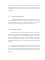
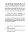
There are two important processes in this project which is vehicles check in and
check out from the parking lot.
Figure 2.1 shows the check in process and figure 2.2
shows the check out process. Both are almost same.
Read Vehicle ID
No
Is the vehicle
registered?
Register the vehicle
info to the database
Yes
Yes
Do not open the
gate
Did the vehicle
check in?
No
Read Vehicle Info
Database
-
Store Check in Info
Open the gate
Close the gate
Figure 2.1
Parking-lot check-in process
12
Read Vehicle ID
No
Is the vehicle
registered?
Do not open the
gate
Yes
No
Did the vehicle
check in?
Yes
Read Vehicle Info
Database
-
Update check out info
Open the gate
Close the gate
Figure 2.2
Parking-lot check out process
13
The system will check whether any registered vehicles come to the parking lot
check in have registered or not. This step is very important as if it had registered; means
the vehicles doesn’t have to check in again. And in the other case, if it is unregistered,
and it doesn't have any check-in or check-out records available, the check-in information
is stored in the database and the barrier will lift off for the vehicle to drive in
Same process for registered car checks out. The identification information for a
checking out vehicle will be searched on the database first. The system will find out the
registered vehicles check in with the date and time and updates it with the check out date
and time. If it is a registered vehicle and it didn't have an unauthorized access, the
system will allow its check-out.
Seems RFID technology is secure, convenient, fast and efficient, so it is suitable
use in security system which security system only can unlock or open the door in the
fastest way when it had detect correct identification ID of the passive tag.
14
2.3
Security Analysis
According to Xun Yi in the journal entitle security analysis of Yang et al.’s
practical password based two server authentication and key exchange system, the usual
or typical protocols for password-based authentication assume a single server which
stores all the passwords which is necessary to authenticate users.
If the server is
compromised, then the user passwords are disclosed. In order to address this issue,
Yang et al. have proposed a system which a practical password is based on two-server
authentication and key exchange protocol, where a front-end server, keeping one share
of a password, and a back-end server, holding another share of the password, cooperate
in authenticating a user and, meanwhile, establishing a secret key with the user. The
user passwords can be determined once the backend server is compromised. Therefore,
the latest or Yang et al.’s protocol has no essential difference from a password-based
single server authentication protocol.
Password-based user authentication is where a user and a server, who share a
password, authenticate each other by exchange of messages. Typical protocols for
password-based authentication assume a single server stores all the passwords which are
necessary to authenticate users. If the server is compromised, due to hacking or being
attack with virus such as Trojan horse, then the user passwords stored in the server are
disclosed.
In Yang et al.’s protocol, a frontend server, keeping one share of a password, and
a backend server, holding another share of the password, cooperate in authenticating a
user and, meanwhile, establishing a secret key with the user. This protocol assumes that
the two servers never collude and aims to keep user passwords secret even if either of
the two servers is compromised. But in practically, attackers may try all kinds of
alternatives to achieve their purpose which is to determine user password. So, this paper
have introduce two ways which are “half-online and half-offline” to attack Yang et al.’s
15
protocol and show that user passwords can be determined once the back-end server is
compromised.
Another support material is from Art Conklin, Glenn Dietrich and Diane Walz in
the journal entitle password based authentication, the concept of a user id and password
is a cost effective and efficient method of maintaining a shared secret between a user and
a computer system. One of the key elements in the password solution for security is a
reliance on human cognitive ability to remember the shared secret .
Traditionally, ability human to remember the password is limited. But with the
introducing of the Internet, e-commerce, and the proliferation of PCs in offices and
schools, the user base has grown both in number and in demographic base. Individual
users no longer have single passwords for single systems, but are presented with the
challenge of remembering numerous passwords for numerous systems, whether from
email, to web accounts, to banking and financial services. Users must to remember
multiple IDs and multiple passwords for the wide range of computer based services they
use.
Have a different password for separate use of ways is important to prevent
password being hacked by stranger or criminal to do some unwanted purpose. So, all of
this has placed a strain on user memory and users have developed memory aides, such as
password lists, to assist them in the task of keeping accounts and passwords straight.
The purpose of this paper is to present a conceptual model of password-based
security across multiple systems connected by user activity. Besides, the effect of user
generated schemes to assist in the user’s management of IDs and passwords, and the
effect of these memory aides on system security have been emphasized. In more details,
it have presents a conceptual model depicting how users and systems can work together
in this function and examines the consequences of the expanding user base and the use
of password memory aids. To achieve desired levels of system wide security will
require an understanding of the cognitive limitations of users and the behaviors which
result from these limitations. The conceptual model presented here illustrates some
opportunities for system wide improvement of password-based risk.
16
There are some conceptual model presented here such as authentication and
human cognitive ability. This entire can illustrates some opportunities for system wide
improvement of password-based risk. The purpose of authentication is to verify that the
specific information presented represents a request to be authentic from a specified
entity. It is important purposely for verifying the identity of an entity which is the basis
for all future rights and privileges granted to the entity. In the basic authentication
process, the entity desiring authentication presents credentials, usually an account ID
and some additional information, to prove that the request is coming from a legitimate
owner of the ID. Today, with grow of the internet and some other technologies, users
interact with multiple systems and can act as a bridge between them connecting their
security mechanisms through password memory aids. Different memory aids can result
in different system cross connections, as does differing system level security
implementations.
systems.
A common password type memory aid can bridge two or more
If one of these ‘connected’ systems has a lower level of security
implementation, then this can be carried over to a higher level system. The actual
degree of system connection depends upon the memory aid and the level of security
implementation on each system.
17
2.4
Low noise Capacitive Sensing Sensor
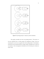
According to the Seunghoon Ko, Hyungcheol Shin, Jaemin Lee, Hongjae Jang
and Kwyro Lee in the paper named low noise capacitive sensor for multi touch mobile
handset’s application, the touch sensor has become the most important and high demand
technology in touch based applications such as mobile device, portable media player and
laptop PC over the last few years. Capacitive sensor which based on the conductive
property of fingers has been widely used in order to realize multi touch recognition such
as zoom in, zoom out and resizing.
Figure 2.3
Behavioral model of capacitive sensing
When a conductive object such as finger approaches to the electrode as shown in
figure 2.3, the fringing fields between two electrodes are directed to the finger, causing
the decrease in capacitance. The touch point can be determined by detecting the largest
change of capacitance and then interpolation scheme will be conducted.
This journal has mentioned the detection of touch point which is infected with
distributed noises such as RF, LCD and EMI interferences. Mostly it is induced from
finger and then coupled to the ITO electrodes. There are several techniques used to
suppress these noises. The difficulty with these approaches is inherent nonlinearity and
18
their performance is limited by low scanning frequency, which can disable the multi
touch recognition.
A new interface which is more effective will be proposed in this paper. Multi
capacitance to voltage converters (C-VC) are operated as time interleaved scheme which
used to enhance the data rate and reject noises. Moreover, the calibration technique is
used to compensate the RC delay of ITO layers also.
The block diagram for the proposed time interleaved architecture of the sensor
interface will be displayed in this paper.
It consist of four C-VC, calibration
comparators, programmable multiplexer and ITO driving logic. Every component has
its own function. C-VCs convert the capacitance changes of ITO electrodes into the
voltage level. CVs amplify the wanted DC voltage level and reject the interferences
coupled to the ITO. The resulting signal level will be converted by SAR-ADC and
filtered once again by IIR filter in DSP. Depending on the touch panel size, the number
of channels and operating C-VC blocks can be controlled by programmable multiplexer.
The output of the C-VCs connects to the calibration comparators, and compared with
controllable Vref to decide the number of conversion times of C-VCs for each channel.
For the calibration circuit, at the channel which is far from the interface, the ITO
electrodes are highly resistive and have much parasitic capacitance to adjacent
electrodes.
This can cause the error being detected.
This detection error will be
worsened as the touch panel size increases. Other than that, the C-VCs output formula
considering ITO’s series resistors and parasitic capacitors can be approximated and it
had been described also in this paper.
In general, this paper has demonstrates an effective filtering technique which can
attenuate and ease noises induced to the ITO layers with 37dB rejection at 50 kHz
frequency. Besides, the time interleaved architecture of C-VCs which can enhance the
data rate up 65Hz of the scanning frequency will be discussed in this paper. It purposely
19
enables the multi touch recognition. The calibration technique used to achieve the
compatibility with all commercial ITO products. Due to its simplicity and low power
consumption cause it suited for touch screen systems which can operate in harsh
environment.
2.5
Conventional Door Security System
Conventional key interlock system is the well known system in the previous year. In
this era, the manufacturer found the new alternatives for door security system such as
electronic access control system. There are much kind of electronic access control system
for security door such as magnetic stripe card, smart card and keypad system.
2.5.1
Key Interlock Conventional
An interlock system is a most well-known security for over past year and it also is a
series of key interlocks applied to associated equipment in such a manner as to allow
operation of the equipment only in a prearranged sequence. Interlocks are applicable to
practically any field wherein human life or protecting property, by an improper
operation or improper sequence of operations. It is necessary to fully appreciate how a
keyed interlock operates and how it works in conjunction with the equipment on which
is mounted.
A typical keyed interlock is comprised of a lock cylinder, support housing, a
moveable locking bolt, and a cam arranged to move the bolt in response to operation of the
correct key. Various styles of interlock housings are available and each style is designed to
mount in a different way depending upon the equipment to which the interlock is to be
installed.
20
One of the most important features a keyed interlock is that key cannot be
removed from all position of the lock bolt. A conventional lockset may allow free
removal of the key regardless of the position of the lock bolt. The function of an
interlock, however, dictates that key be held in the lock cylinder unless the lock bolt is in
a predetermined position. Possession of the key ensures that the associated device has
been locked in a known safe position.
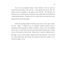
About the operating principle of interlock system, there are four steps to unlock
the lock.
Figure 2.4 illustrates how an individual interlock typically works in
conjunction with the equipment to which it is installed. In figure 2.4 (a), the controlled
device (such as a switch) cannot move from its normal position (whether open or closed)
because of the position of the lock bolt. When the key is turned to withdraw the lock
bolt (figure 2.4 (b) ), the key becomes “trapped” and the controlled device is moved, the
key remains held because the lock bolt can no longer be physically extended so as to
free the key (figure 2.4 (c)) .
21
Figure 2.4 Operating principle of a simple key interlock mechanism
The typically controlled device has two operating positions. If the intent is to
lock the controlled device in either position, the arrangement of figure 2.4(a) may
instead provide a recess on two opposite sides of the rotating member. In this manner,
the lock bolt can be extended and the key released with the controlled device in either of
two positions. Such an arrangement is described as (L-O-C) locked open or closed (see
figure 2.4(d)).
22
2.5.2
Magnetic and Smart Card
The magnetic card is the one of electronic access control system widely used in
door security system. A basic access control system consists of a card reader and a
controller.
When the system user presents or put a card to the reader, the reader
interprets the information encoded on the card and sends it to the controller. The
controller accepts the information from the reader and compares it to information stored
in its memory. The controller then grants or denies access by commanding electric
locking device on the door to unlock or remain locked.
There are many kinds of magnetic card such as a magnetic stripe card. This card
is very similar to a standard credit card; the information is encoded on a strip of
magnetic material applied to one side of the card, exactly like a conventional credit card.
The information is written on the magnetic strip in a manner similar to tape used in a
tape recorder. When the card is inserted into the reader, this head rides on the magnetic
stripe and reads the information it.
Nowadays the manufactured found a new method for security access system they
call a smart card. The advantage smart cards have over magnetic stripe cards is that the
smart card contains the computer chip which stores the password or PIN. Smart card is
convenient for security purpose. The only disadvantage for this kind of security system
is user needs report directly to police or related organization once found disappear the
card. It is very dangerous when someone picks up the card, and unexpected thing may
occur. To prevent all of this unwanted thing from happening, double security system are
going to introduce, no need to worry when the card is disappear, but requiring user to
report to police also for further action. The only reason for no need to worry when the
card is disappear compared with one level of security is the criminal or thieves still need
to know the 6 digit password just can break in the house. Some more, the number on
pad can be arranged based on preference of designers. So, it is hard to break the
password.
23
2. 6
Keypad Security System
In this era, keypad security system is the most well known method for security
system widely used for door security system. A basic access control system consists of
a key personal or information that user key in and a controller. When the user key in the
personal key, the information encoded sends it to the controller. The controller accepts
the information from the reader and compares it to information stored in its memory.
The controller then grants or denies access by commanding electric locking device on
the door to unlock or remain locked.
There are many kinds of keypad security system in the market. Mostly the
keypad systems using a digital system to encoded the information and compare it to
information or password number stored in its memory.
When the user key in the
personal key, the information encoded and sends it to the controller. The controller
accepts the information from the reader and compares it to information stored in its
memory. The controller then grants or denies access by commanding electric locking
device on the door to unlock or remain locked.
If a valid code is entered on the keypad, the lock release will operate for a preset
duration. The keypad has one green and one red LED to indicate the system status to the
user; besides, buzzer and LCD display use as an indicator also.
The green LED
indicates that the lock release is operating, while the red LED indicates an invalid entry.
Buzzer will beep once when the password entered is correct. Otherwise, alarm on when
the password entered is wrong. LCD display will display the instruction for user to
follow.
24
2.7
Microcontroller PIC16F727A
This section reviews the reason of choosing microcontroller. A microcontroller
(or MCU) is a computer-on-a-chip. It is a type of microprocessor emphasizing selfsufficiency and cost-effectiveness, in contrast to a general-purpose microprocessor (the
kind used in a PC). The only difference between a microcontroller and a microprocessor
is that a microprocessor has three parts - ALU, Control Unit and registers (like memory),
while the microcontroller has additional elements like ROM, RAM etc. So, the circuit
for microcontroller is simpler compared with microprocessor.
Microcontroller
processors are designed to fill a smaller, more focused variety of roles while making use
of less expensive and less complex circuitry. The main advantage of a microcontroller is
that it allows electronic automation in situations where a full-sized computer is not
needed.
Besides, microcontroller is cheaper compared with microprocessor.
Fully
functional personal computer microprocessor is a complex device containing densely
packed micro circuitry. Most microprocessors also require gold plating on every single
processor pin used to connect to the computer's motherboard, adding yet another
expense to an already difficult to produce item. When compared to the simple circuit
architecture found in the microprocessors of microcontrollers, it is easy to see that
microcontrollers save money. When the most modern technical engineering is applied
to a microcontroller it allows the device to be extremely compact, making
microcontrollers popular within mobile devices such as cell phones and PDAs.
25
2.7.1 Microcontroller PIC16F727 Special Features
Simplify features of microcontroller PIC16F727 is as below:
a) Interrupt capability
b) 8-Level Deep Hardware Stack
c) Direct, Indirect or Relative Addressing modes
d) Processor Read Access to Program Memory
e) Precision Internal Oscillator
a. 16MHz or 500kHz operation
b. Factory calibrated to ±1%, typical
c. Software tunable
d. Software selectable +1, +2, +4 or +8 divider
f) Multiplexed Master Clear with Pull-up or Input Pin
g) 14 channels of 8-bit Analog-to-Digital (A/D) converter where conversion is
also available during sleep mode
h) Enhanced Timer1:
a.
Dedicated low-power 32 kHz oscillator
b.
16-bit timer/counter with pre-scaler
c.
External Gate Input mode with toggle and single shot modes
d.
Interrupt-on-gate completion
i) 2 capture/compare/PWM functions
j) Synchronous Serial Port (SSP):
a. SPI (Master/Slave)
b. I²C™ (Slave) with Address Mask
k) Addressable Universal Asynchronous Receiver Transmitter (AUART).
l)
mTouch™ Sensing Oscillator Module which is up to 16 input channels.
26
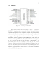
2.7.2 Pin Diagram
Figure 2.5
Pin Diagram of PIC16F727
The pin diagram for the PIC 16F727A is as shown in figure 2.5. In this project,
PIC16F727 is being chosen due to its powerful I/O port, Addressable Universal
Synchronous Asynchronous Receiver Transmitter (AUSART) and capacitive sensing
module (m touch). Capacitive sensing module used to replace keypad in usual password
security system. So, it might reduce cost and more convenient and efficient compared to
4X4 keypad.
AUSART is needed due to the second level of security involve the
scanning the passive tag on RFID reader. The specific identification number of passive
tag will be read; the data then will sent and process in microcontroller.
So,
microcontroller chose need have a capability to receive the data from external.
Comparison will be occurred and the data will be displayed on LCD display. Since this
project have many identify signal such as LED, buzzer, relay, LCD display and motor,
so powerful I/O port is needed. Overall, PIC16F727 is the suitable microcontroller
which can fulfill all of the requirements.
27
2.8
Microchip MPLAB ICD 2
The MPLAB ICD 2 is a low-cost in-circuit debugger (ICD) and in-circuit serial
programmer. MPLAB ICD 2 is intended to be used as an evaluation, debugging and
programming purpose in a laboratory environment.
It can provide features which
consist of real time and single step code execution, breakpoints, register and variable
watch or modify, in circuit debugging, target VDD monitor, diagnostic LED, MPLAB
IDE user interface and RS 232 serial or USB interface to a host PC.
MPLAB ICD 2 can be used for debugging source code in own application,
debugging hardware in real time and it becomes a supported device used Microchip’s
ICSP protocol.
2.8.1 Modular Interface Connections
MPLAB ICD 2 is connected to the target PIC MCU with the modular interface
cable, which is a six conductor cable. The pin numbering for the MPLAB ICD 2
connector is shown from the bottom of the target PC board in Figure 2.6.
28
Figure 2.6
Pin numbering for modular connector
Figure 2.6 shows the interconnections of the MPLAB ICD 2 to the modular
connector on the target board. There are six pins on the ICD connector, but only five are
used. The diagram also shows the wiring from the connector to the PIC MCU device on
the target PC board. A pull-up resistor (usually around 10k Ohm) is recommended to be
connected from the VPP/MCLR line to VDD so that the line may be strobe low to reset
the PIC MCU. Although pin 2 (VDD) can supply a limited amount of power to the
target application under certain conditions, for the purposes of these descriptions, pins 2
and 3 (VSS) are omitted. They are shown on the diagram for completeness, but in the
following descriptions only three lines are active and relevant to core MPLAB ICD 2
operation: VPP/MCLR, PGC and PGD.
2.8.2 Debug Mode
There are two steps to use MPLAB ICD 2 as a debugger. The first requires that
an application be programmed into the target PIC MCU. The second uses the internal
in-circuit debug hardware of the target Flash PIC MCU to run and test the application
program. These two steps are directly related to the MPLAB IDE operations which
include program the code into the target and use the debugger to set breakpoints and run.
29
If the target PIC MCU cannot be programmed correctly, MPLAB ICD 2 will not
be able to debug. Figure 2.7 shows the basic interconnections required for programming.
Figure 2.7
Connections for programming
A simplified diagram of some of the internal interface circuitry of the MPLAB
ICD 2 is shown. No clock is needed on the target PIC MCU if it is for programming,
but power must be supplied. When in the programming mode, MPLAB ICD 2 puts
programming levels on VPP, sends clock pulses on PGC and serial data via PGD. To
verify that the part has been programmed correctly, clocks are sent to PGC and data is
read back from PGD. This conforms to the ICSP protocol of the PIC MCU under
development. Figure 2.8 illustrates the MPLAB ICD 2 ready for debugging.
30
Figure 2.8
Illustrates the MPLAB ICD 2 ready for debugging.
2.8.3 Programmer Mode
When use the Programmer, the in circuit debug registers should be disabled in
the MPLAB IDE so the MPLAB ICD 2 will program only when the target application
code and the configuration bits (and EEPROM data, if available and selected) have burnt
into the target PIC MCU. The debug executive will not be loaded. In this mode the
MPLAB ICD 2 can only toggle the MCLR line to reset and start the target.
A
breakpoint cannot be set, and register contents cannot be seen or altered. The MPLAB
ICD 2 programs the target using ICSP. No clock is required while programming, and all
modes of the processor can be programmed, including code-protect, watchdog Timer
enabled and table read protect.
31
2.9
M Touchpad (Capacitive Touch Sensor)
Touch sensing becoming alternatives to traditional mechanical button or push
button switch user interfaces, because it requires no mechanical movement, and it
enables a completely sealed and modern-looking design.
Expanding beyond the
consumer market, touch sensing is beginning to take hold in medical, industrial and
automotive applications for reasons such as improved aesthetics, reduced maintenance
and lower cost.
A capacitive touch sensor is a copper pad area created on the surface of a printed
circuit board. It creates a parasitic capacitance to ground. When a person touches the
sensor, or it’s covering such as plastic, glass, etc, the person’s finger introduces an
additional glass-finger-ground capacitance.
That capacitance is in parallel to the
parasitic one. As capacitors in parallel are added, a finger approaching the pad will
increase the total capacitance. This change is the criteria needed to detect a touch.
Being a microcontroller based solution; capacitive touch can also be used to
drive a LED, a buzzer, LCD Display or to communicate with the main processor or the
rest of the system.
On the microcontroller PIC16F, the on chip capacitor sense module used to
create a relaxation oscillator to perform touch sensing. The period or frequency of the
relaxation oscillator can be measured, and when the sensor is touched, the frequency will
drop and the period will increase, indicating a touched condition.
Since capacitive sensing module (CSM) is a frequency-based method, timer
method is used. Basically, Timer 2 is used as the timer resource instead of using Timer
0 due to it has greater flexibility in defining time base. On the other hand, Timer 1 gate
is used as a counter. It will increment at every rising edge of capacitive sensing module
output frequency. The value on the Timer 1 will be a measure for CSM oscillator
32
frequency. The completion of Timer 1 gate event, triggered by Timer 2 overflow, will
generate a Timer 1 gate interrupt. When servicing the interrupt, the value from the
Timer 1 can be read to determine the oscillator frequency. In detailed, capacitance of
the pad alone results in a corresponding square wave frequency. When the PR2 value is
matched, the current count value in Timer 1 will be read and stored as reference. Once
the finger is touched, the RC time constant of the oscillator increases and thus results in
a decrease of frequency of the square wave output. Therefore, on the next interrupt, the
Timer 1 value will be smaller. Using a software algorithm to compare the difference
between these values, the sensor can be identified as pressed or not pressed.
When a pad is touched, the frequency on the CSM changes due to the extra
capacitance from the finger. The change in frequency is noted, number of password was
being identified, comparison occurred and result will be shown on LCD display.
Microchip’s mTouch sensing solutions allow designers to integrate touch sensing
with application code in a single microcontroller, reducing total system cost. Microchip
offers a broad portfolio of low power, low cost & flexible solutions for keys or sliders
and touch screen controllers. Get to market faster using our easy GUI-based tools, free
source code and low-cost development tools.
There are two types of mTouch which consist of:
i)
mTouch Capacitive Sensing technology
It has longer battery life with eXtreme Low Power MCUs; capacitive sensing in
less than 5 μA; high noise immunity and emissions and no external components
required.
ii)
mTouch Inductive Sensing technology
It use polished or brushed metal surfaces which including stainless steel and
aluminum. Besides it can sense through gloves, create water proof designs and
deploy the Braille friendly interfaces.
33
The response of the sensor to fingertip touch is influenced by many factors which
include touch areas, voltage and current levels, ambient humidity, static buildup, and so
on. Most of these factors have been accounted for in designing the demo application
firmware, and are based on typical environmental values, and certain assumed constants.
2.10
RFID
RFID (Radio Frequency Identification) is a technology which is used to identify
or detect an object. The purpose of an RFID system is to enable data to be transmitted
by a portable device, called a tag, which is read by an RFID reader and processed
according to the needs of a particular application. In other word, the communication
takes place between a reader (interrogator) and a transponder (tag). The data transmitted
by the tag may provide identification or location information, or specifics about the
product tagged, such as price, color, date of purchase, etc.
RFID quickly gained
attention because of its ability to track moving objects. Therefore, RFID technology has
been used by thousands of companies for a decade or more. RFID technology is similar
to the bar code identification systems we see in retail stores everyday; however one big
difference between RFID and bar code technology is that RFID does not rely on the lineof-sight reading that bar code scanning requires to work.
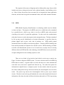
There are two kinds of tag involved and which is active tag or passive tag.
Figure 2.9 shows a diagram of RFID system. To retrieve the data stored on an RFID tag,
RFID reader is needed. A typical reader is a device that has one or more antennas that
emit radio waves and receive signals back from the tag. The reader then passes the
information in digital form to a computer system. In more details, when the tag enters
the reader reading field, the tag will be activated by the electromagnetic wave from the
reader. The passive tag converts the electromagnetic field to power up its internal
circuits. Then the circuit in the tag will modulate the waves and transmit back the stored
information. After that, the reader will decode the data and send it to CPU for processing.
34
Figure 2.9
Diagram of RFID system
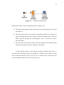
RFID system consists of three components (Refer to Figure 2.10):
a) The antenna (Interrogator) emits radio signals to activate the tag and to read and
write data to it.
b) The reader emits radio waves in ranges of anywhere from one inch to 100 feet or
more, depending upon its power output and the radio frequency used. When an
RFID tag passes through the electromagnetic zone, it detects the reader's
activation signal.
c) The reader decodes the data encoded in the tag's integrated circuit (silicon chip)
and the data is passed to the host computer for processing
A reader typically contains a radio frequency module (transmitter and receiver), a
control unit and a coupling element to the transponder. In addition, many readers are fitted
with an additional interface (RS 232, RS 485, etc) to enable them to forward the data
received to another system (PC, robot control system, etc).
35
Figure 2.10
Transponder and Reader of RFID system
The transponder, which represents the actual data-carrying device of an RFID
system, normally consists of a coupling element and an electronic microchip. When the
transponder, which does not usually possess its own voltage supply (battery), is not within
the interrogation zone of a reader it is totally passive. The power required to activate the
transponder is supplied to the transponder through the coupling unit (contactless), as are the
timing pulse and data.
The RFID tag is essentially a memory device with a means of revealing and
communicating its memory contents, when prompted (scanned) to do so. The memory
consist of a plurality of binary (two state) digits, also known as bits, and the communication
comprises RF reception and transmissions means. The binary data (bits) are formed into
binary words comprising typically 8, 16 or 32 bits that can make up letters and numbers in
the same manner as in computing, the Internet and ‘texts’ on a mobile phone. The tag may
comprise an electronic circuit (printed circuit board) with its own power supply – an active
device; or be a very low power integrated circuit that is able to gain enough energy from the
scanner/reader RF signal to actually power itself for long enough to transmit the contents of
its memory, so called passive device. In its passive embodiment RFID tag transmission
power is very low and measured in millionths of a watt i.e. microwatts (μW).
36
2.10.1 Type of RFID Tag and Its Frequencies
2.10.1.1 Type of RFID Tag
The tags communicate to a RFID reader via radio frequency. The typical types of
RFID technologies are active, semi passive and passive. The terms active, semi passive and
passive is referring to the RFID tags. Below are details of each type of RFID tag.
Passive
No internal supply is needed. The minute the electrical current induced in the
antenna by the incoming radio frequency signal provides just enough power for the
CMOS integrated circuit in the tag to power up and transmits a response. The antenna
has to be designed to both collect powers from incoming signal and also to transmit the
outbound backscatter signal. The response of the RFID tag is not just an ID number the
tag can contain nonvolatile EEPROM for storing data.
It uses the radio frequency from the reader to transmit their signal. Passive tags
will generally have their data permanently burned into the tag when it is made, although
some can be rewritten.
Semi Passive
It is similar to passive tag, the only difference is it have addition of a small battery.
This battery allows the tag IC to be constantly powered which removes the need of an aerial
to be designed to collect power from the incoming signal. As semi passive tag is preenergized, they can be read more reliably in this more difficult environment.
37
Active
Active tag has their own internal power source which is used to power any ICs
that generate the outgoing signal. They are more reliable and sophisticated (fewer
errors) due to the ability for active tag to conduct a session with a reader. Because of
their onboard power supply also transmit at higher power level than passive tags,
allowing them to be more effective in “RF challenged” environments such as water,
metal or at longer distances. Active tags have on board battery for power to transmit
data signal over a greater distance and power random access memory (RAM) giving
them the ability to store up to 32,000 bytes of data. A battery can live up to 10 years and
have practical ranges of hundred of meters. Types of tags that were used in the RFID
system are ISO card, clamshell card and also soft label.
Tag used in this project is passive tag and the model of RFID reader is RFIDIDR-232N.
Benefits of RFID tag:
a) Tags can be read from a distance and from any orientation.
b) Capabilities of read and write, which allow data to be changed dynamically at
any time.
c) Multiple tags can be read simultaneously and in bulk very quickly.
d) RF tags can easily embed into any non-metallic product. This feature allows the
tag to work in harsh environment providing permanent identification for the life
of the product.
38
CHAPTER 3
METHODOLOGY
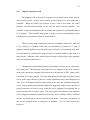
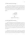
3.1
Process Flow for Double Security System Used M Touchpad and RFID
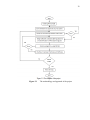
The flow diagram as shown in Figure 3.1 shows the process flow of the project.
All the process mentioned are important in completing the project. First of all, the
project requires study of basic principles capacitive sensing concept, frequency
measurement, microcontroller PIC family, LCD display and RFID (UART concept).
Next, additional system consists of hardware and software is designed. Install the safety
security system to the door. Double security system plays an important role to ensure
the safety of house. Previous project always involves one level of security, but this
project involves two level of security.
First level is entering 6 digit password by
touching the number on m touchpad while second level is scanning the passive tag on
RFID reader. The project is considered done when all of the requirements are fulfilled.
The flow of project is as shown in figure 3.1.
39
Figure 3.1
The methodology and approach of the project
40
3.2
Hardware Design for Double Security System
Microcontroller PIC 16F727A is known as a central processing Unit or CPU.
There are many others supporting devices that been used on this project which includes
power regulator circuit, reset circuit, clock circuit, some input and output interface
devices. Besides, there are other components that must also be included so that the
system will operate without any problem.
System clock generate the correct and stable frequency to supply it to
PIC16F727. The reset circuit determines when to stop or initialize the PIC16F727.
Power regulator circuit will supply the voltage for PIC16F727 and whole circuit. The
block diagram for the double security system used m Touchpad and RFID is as shown in
Figure 3.2.
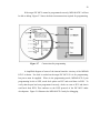
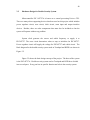
Figure 3.2 shows the basic design concept of the project. The heart of the system
is the PIC16F727A. Double security system used m Touchpad and RFID have divided
into several parts. Every part has its specific function and role in the security system.
41
Power Regulator
Circuit
PIC16F727A
LCD Display
Reset Circuit
Buzzer
Clock Circuit
Relay
M Touchpad
RFID circuit
Figure 3.2
The design concept of the double security system
3.2.1 Power Supply Unit
PIC16F727A used power around 1.75W or 350mA at 5V to function. The
design of this power circuit enough for supporting the whole system without any
additional devices in the circuit board. If the output voltage drops a while, it means the
supplied current is not enough. An additional power supply unit need be added so the
system can perform properly. Designer can either choose to use AC to DC adaptor or
12V battery to power up the circuit. In this project, AC to DC adaptor chose as power
supply. However, higher input voltage will produce more heat at LM7805 voltage
regulator. The voltage regulator will broke easily if the power is turn on for a long time.
The typical voltage is 12V. Anyhow, LM7805 will generate some heat at 12V also.
Only the amount of heat generated is not much as other value of input voltage. For more
user friendly, it is better to have both power connector in circuit which consist of AC to
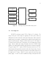
DC adaptor and 12 V battery. Diode D1 is used to protect the circuit from wrong
polarity supply. C1 and C3 are used to stabilize the voltage at the input side of the
42
LM7805 voltage regulator, while another two capacitor C2 and C4 used to stabilize the
voltage at the output side of the LM7805 voltage regulator. LED yellow used to indicate
the power status of circuit; it will turn on when the power is in correct polarity. R1 is a
resistor used to protect LED from excessive current that will burn the LED. The voltage
regulator circuit is as show in figure 3.3.
Figure 3.3
The voltage regulator circuit
3.2.2 Clock Generator Unit
Clock system should able to produce and supply stable and nice clock signal to
the CPU. There are 2 methods to build the clock system which include digital oscillator
and another method is used of crystal and discrete component. The design by using
crystal and discrete components as the clock system is more economy compared with the
digital oscillator. If any other devices need the clock signal, please use a different
inverter. By doing this, we can reduce the load effect on the oscillator which could
disturb the operation. The clock generator circuit is shown in Figure 3.4.
43
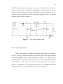
Figure 3.4
3.2.3
The clock generator circuit
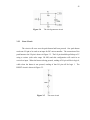
Reset Circuit
The circuit will reset once the push button had been pressed. One push button
needs one I/O pin to be used as an input for PIC microcontroller. The connection of the
push button to the I/O pin is shown in Figure 3.5. The I/O pin should be pulled up to 5V
using a resistor (with value range 1K-10K) and this configuration will result in an
active-low input. When the button is being pressed, reading of I/O pin will be in logic 0,
while when the button is not pressed, reading of that I/O pin will be logic 1. The
RESET circuit is shown in Figure 3.5.
Figure 3.5
The reset circuit
44
3.2.3 Interface circuit
3.2.3.1 Interface m Touch with PIC16F727
To utilize the capacitive sensing module in PIC16F727, all the copper pads must
be connected to the capacitive channels of PIC microcontroller and set those pins to
analog pins. This step is very vital before proceeding to software algorithm. In this
project, the m Touch or touch pad is connected as shown in Figure3.6.
Figure 3.6
The m Touchpad connection
Theoretically, to know whether the touch pad has been touched or not is by
determining the change of capacitance. Before a finger presses the pad, the PCB pad
itself has a capacitance, Cp. However, if a finger presses the copper pad, another
capacitance, Cf is introduced where it is in parallel with Cp. Thus, the equivalent of
capacitance increases after finger press. Additionally, the capacitance change will result
in change in frequency. To scan a pad, frequency change on copper pad is measured. In
this project, the touch pad is sensed by capacitive sensing module (CSM) at fixed time
interval. The benefit of this method is that it does not need external oscillator since the
module has its own oscillator embedded. The frequency of each pad at rest is averaged.
It is low cost and user friendly. The material required to make the m touchpad is just a
pieces of copper pad.
45
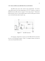
3.2.3.2 Interface RFID reader (RFID-IDR-232N) with PIC16F876A
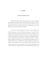
The RFID reader comes with a cable for data communication. The cable is
consist DB9 serial port for data communication to PC, RJ-11 connector to connect to
RFID Reader and a USB connector to supply 5V for the reader. Figure 3.7 illustrates the
RFID connection. There is a circuit required connect to the PIC in this project in order to
receive the identification number of passive tag.
Figure 3.7
The RFID connection
For this project, designer has to cut the wire of the DB9 Serial Port and connect
the wire to a 2510-04 female connector. Table 3.1 is example of output wire when user
cut the wire of female DB9 Serial Port.
46
Example of wire color output
Table 3.1: Indication of RFID wire color
Color
Pin function
Connection
Red
Ground
GND
Yellow
Vcc
VCC/ +5V
White
Rx
Not Connected
Green
Tx
Data
The function for each color of wires for RFID reader model IDR-232N is as
shown in table 3.1. However, different types of RFID reader sometimes have different
color of output wire. So, it is important to refer user manual.
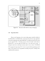
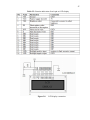
3.2.3.3 Interface LCD (2x 16 Character) with PIC16F727
To use the LCD, First of all has to solder 16 pin header pin to it. LCD model
used in this project is JHD162A. LCD connection pin and function of each pin is shown
in table 3.2 and the connection shows in figure 3.8.
47
Table 3.2: Function indication of each pin on LCD display
Figure 3.8
LCD display connection
48
3.2.4 Output Circuit
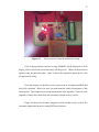
3.2.4.1 LED as output for PIC microcontroller
LED connection shows in figure 3.9 is for output result showing of m Touchpad.
Once the 6 digit password entered is correct, LED green will on, otherwise, the LED red
will on.
Figure 3.9
LED connection for first level of security
LED connection shows in figure 3.10 is for output result showing of RFID.
Once it is processing, LED blue is on. LED red will on when the ID is incorrect.
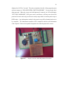
Figure 3.10
LED connection for second level of security
49
3.2.4.2 Buzzer as output for PIC microcontroller
When the output is in logic 1, the buzzer will activate (beep), while when the
output is in logic 0, the buzzer will deactivate. In project, it used as an indicator to
indicate whether the password and ID is correct and match. When the 6 digit password
entered is correct, buzzer will beep once. Otherwise, when the password entered is
wrong, the buzzer will off and alarm will on. Connection for buzzer is as shown in
figure 3.11.
Figure 3.11
Buzzer connection
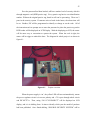
3.2.4.3 Relay as output of PIC microcontroller
Relay required for output to connect with solenoid at the door in real application.
In other name, A relay also known as an electrically operated switch. Relay is the one of
electromechanical tools which converts electrical signal to mechanical movement.
Relays are used where it is necessary to control a circuit by a low-power signal. There is
included wire coil at steel core and connector. When the power has been supply to the
coil, the current will be flow and magnetic density will be produce a movement for close
one of connector.
Microcontroller cannot control relay indirect. Transistor has been requirement
for interface. High rate at base transistor will be on the transistor and enable the relay.
Relay can be connecting to the other electric devices at connector. In real application
50
relay must be connected to the solenoid for control the door. Transistor requirement for
connection to the solenoid, increase the volt from 5V to 12V to enable the solenoid.
When the relay closed the connector which is sent high logic to port RA5 at
microcontroller, solenoid will be pushed the load.
51
3.3
Software Implementation
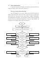
A flow chart of the password entering system operation is drawn first before the
coding work begins. The flow chart is shows in figure 3.12.
First level of security (Password Entering)
First of all, prompt the user to enter 6 digits password, and then compare the
entering numerical password with the stall value. 6 digits password are ensured match
with the stall value. If the result is correct, then the string “CORRECT PASSWORD”
will be displayed on LCD display. Green LED turn on, buzzer will beep once and can
proceed to the next step which is RFID identification. Otherwise, string “ERROR” will
be displayed on LCD display, LED red and alarm will turn on.
Start
Enter 6 digits Password
Compare keying value with stall value.
Ye
s
No
1st Password
Correct
Keying value == Stall value
Keying value == Stall value
Ye
s
Keying value == Stall value
Ye
s
Keying value != Stall value
No
2nd Password
Correct
Keying value != Stall value
No
3rd Password
Correct
Keying value != Stall value
4th Password
Correct
Keying value == Stall value
Ye
s
No
5th Password
Correct
A
Keying value != Stall value
B
52
Figure 3.12
The password entering circuit
53
Second Level of Security (Identification)
Identification process will only begin once the entering numerical password in
the first stage success. RFID identification process starting with scanning the RFID
passive tags on RFID reader. Next step is doing a comparison between the RFID
passive tags ID with the stalling value. RFID identification number and user name will
be displayed on LCD display, buzzer will beep once and relay will turn on. Otherwise,
the tag ID and string “user not found” will be displayed.
Figure 3.13
The identification scanning circuit
54
CHAPTER 4
RESULTS AND DISCUSSION
Chapter 4 will show the results from the proposed system. There are some figure
shows the respond of output or indicator device once the password is correct and fail.
After entering password, next stage is scanning passive tag on RFID reader, some
indicator device also for the second level of security. Instructions on how to use the
double security system are introduced in this chapter.
In this project, PIC microcontroller was using as the main controller in the
double security system. It acts as the heart for the whole project. First of all, PIC used
to identify which button (touch sensor) had been pressed on m Touchpad. The m
Touchpad used the capacitive sensing concept to operate. Capacitive sensing module is
a frequency based method. The capacitance will change when the finger had pressed on
the pad. Changing of capacitance will lead to the change of frequency. Frequency
change on copper pad is measured in order to determine which pad being touched. The
numerical number on the m Touchpad can be arranged according to the preference of
designers. Plus, the number won’t be shown on the pad. Designer only needs to change
software coding in order to achieve this purpose. The percentage of breaking case can
be reduced. It becomes a tough and hard work to hack and break the unknown password.
55
Even the password had been hacked; still have another level of security which is
through magnetic card (RFID passive tag). Every passive tag has its own identification
number. Without the original passive tag, break in still can be preventing. There are 2
parts in the security system. If someone tries to break in the house, the alarm siren will
be on. Besides, PIC will be programmed to identify or change or set the code. All of
the instruction such as prompt user to enter the password or place the passive tag on the
RFID reader will be displayed on LCD Display. With the displaying on LCD, the owner
will be more easy or convenient to operate the system. When the code is right, the
motor will be trigger to unlock the door. The diagram for whole project is as shown in
figure 4.1.
Figure 4.1
Project overview
When the power supply is ‘on’, the yellow LED will turn on immediately, means
the power regulator circuit is in correct polarity and +5V is pass through whole circuit
and PIC16F727A. Then, string “2011 FYP PROJECT” will be displayed on LCD
display, and it is in shifting form. It aims to identify which year the model of products
had been published. Once finish shifting, “DOUBLE SECURITY SYSTEM” will be
56
displayed on LCD for 2 second. This aims to introduce the title of the proposed project
and next sentence is “PLEASE ENTER 6 DIGIT PASSWORD”. User need enter the 6
digit password. When the correct and valid password is entered, the LCD will display
“SUCCESS PASSWORD”, LED green turn on and buzzer will beep once shows the
password is correct and can go to the next security stage which is scan the passive tag on
RFID reader. Any information encoded in the passive tag will be obtained and receive
by controller. The identification number will be compared with the stall information
value. Figure 4.2 shows the respond of output device when the password is correct.
Figure 4.2
Project overview when the password is correct.
57
Figure 4.3
Project overview when the password is wrong
If the 6 digit password entered is wrong, “ERROR” will be displayed on LCD
display, LED red will turn on and the buzzer will beep twice. Whole circuit need reset
again to enter the password again. Figure 3 shows the respond of output device when
the password is wrong.
From this chapter, the double security system used m Touchpad and RFID had
been fully explained. Hence the users can understand the whole development of this
alarm system. The complete source code had attached in the appendix. Users can refer
appendix to know more detail about the operation of double security system.
Figure 4.4 shows the schematic diagram of whole double security system. The
schematic diagram had drawn by using DXP Protel software.
58
Figure 4.4
Schematic diagram of double security system
59
CHAPTER 5
CONCLUSIONS AND RECOMMENDATIONS
As a conclusion, the capacitive sensing concept which is based on the frequency
measurement had applied in this project. One complete hardware of double security system
used m Touchpad and RFID had completely built. Software used to control the project
successfully designed. This project can work and give a desired output. Since it is double
level of security, the safety of house will be increased and make society feel secure. The
specifications of the security system are universal LCD alarm system, keyless, flexible, low
cost, repairable, reprogrammable auto reset.
Limitation
This version of security system is designed in conjunction to the current
Malaysian demand at this point of time. Breaking case nowadays is dangerous, although
it is best suited to the targeted group so far but it may be irrelevant and ineffective to the
future generation. However, breaking case or criminal activities sure is more serious in
future, so this level of security scare cannot guarantee safety for the future generation.
In my opinion, this system design can be further enhanced and upgraded to another
level.
60
Future work/ Recommendations
Home security is something to not take lightly, especially given today’s faltering
and unstable economy. As people get desperate to make a quick buck some will turn to
crime, making our homes, businesses, and families more vulnerable than ever before.
That’s why it’s time to take action and be pro-active. Below are some recommendations
to make the security system better and more secure.
a) Manual Authentication
If black out occurs, the users still can certain manual key to activate the lock
and access the door. When break out, owner or users many times cannot unlock the
lock and enter the house. So, it become not fully efficient because user only can
unlock the door when have current.
b) Wireless home security
Low cost, user-friendly and lasting. Plus, it is suitable for double story
house. It can ensure safety for big area of housing.
c) Face recognize home security system
The door only can be access once the system detects the match face (image
processing). This method is very efficient because the system only recognize the
correct face which is match with the stall image.
d) Finger print security system
Fingerprint identification systems are biometric solutions that contain
digital fingerprint records of authorized personnel and do not open the door,
unless the user's fingerprint matches with the stored digital print. The latest door
61
security systems record the iris patterns of authorized users, and use alarms to
alert the control room in case an unauthorized person tries to open the door.
Usually, this kind of security system used in large organizations and government
agencies that are manufactured according to the security needs of the
organization.
e) Laser technologies
Laser technology is also used in some door security systems, in which an
invisible beam of laser surrounds the door. If an intruder or any other thing gets
in the way of these beams, the circuit is interrupted and an alarm is activated to
alert security.
Door security systems also use motion sensors to detect
movement in front and around a door.
From this project, I gain a lot of knowledge whether in software (various
types of software such as DXP PROTEL, MPLAB, C programming) or hardware
(various types of components, solder skill, testing and troubleshoot). All of this
knowledge will be useful for me to prepare myself for the future career especially in
electronic industry which is changing rapidly.
62
REFERENCE
[1]
Seunghoon Ko1, Hyungcheol Shin1, Jaemin Lee1, Hongjae Jang, Kwyro
Lee1Low Noise,
Capacitive Sensor for Multi-touch Mobile handset’s
applications, IEEE Asian Solid-State Circuits Conference, 2010
[2]
Robert Biddle, Mohammad Mannan, P.C. van Oorschot, Tara Whalen, User
Study, Analysis and Usable Security of Passwords based on Digital Objects,
IEEE, 2011
[3]
Xun Yi, Security Analysis of Yang et al.’s Practical Password-Based Two-Server
Authentication and Key Exchange System, Fourth International Conference on
Network and System Security, 2010
[4]
Art Conklin1, Glenn Dietrich2, Diane Walz, Password-Based Authentication: A
System Perspective, IEEE, 2004
[5]
Yossef Oren and Adi Shamir, Remote Password Extraction from RFID Tags,
IEEE Transactions On Computers, VOL. 56, 2007
[6]
Zeydin PALA* and Nihat INAN, Smart Parking Applications Using RFID
Technology.
[7]
Penttila, K., Keskilammi, M,. Sydanheimo, L., Kivikoski, M.,2006. Radio
frequency technology for automated manufacturing and logistics control.
International Journal
OfAdvanced Manufacturing Technology, 31 (1-2): 116-124.
[8]
Zhang, L., 2005. An Improved Approach to Security and Privacy of RFID
application System. Wireless Communications, Networking and Mobile
Computing. International Conference. (2): 1195- 1198.
[9]
J O’Dowd, A Callanan, G. Banarie, and E. Company-Bosch, “Capacitive sensor
interfacing using sigma-delta techniques,” IEEE Sensors, pp. 951– 954, Oct.Nov. 2005.
10]
K.Martin, “Improved Circuits for the Realization of Switched Capacitor Filters”
IEEE Trans. Circuits and Systems, pp237-244, April. 1980.
63
Appendix A
PROGRAM CODING OF DOUBLE SECURITY SYSTEM USED M TOUCHPAD
AND RFID
//==============================================================
//
NAME: AMY WONG AI LING
//
COURSE: 4 SEL
//
DEPARTMENT: MICE
//
FYP TITLE: DOUBLE SECURITY SYSTEM USED M TOUCHPAD AND RFID
//
SUPERVISOR: DR MUHAMMAD NASIR BIN IBRAHIM
//==============================================================
#include
#include
<pic.h>
"FYP_Lib.h"
//==============================================================
//
CONFIGURATION FOR MICROCONTROLLER
//==============================================================
__CONFIG(0x3CE4);
//==============================================================
//
DEFINE
//==============================================================
#define NUM_ROW
3
#define NUM_COL
3
//==============================================================
//
VARIABLE USED IN PROGRAM
//==============================================================
unsigned int
reading[NUM_BTTNS];
unsigned int
average[NUM_BTTNS];
unsigned int
threshold;
unsigned char
index;
unsigned int
threshold4;
BButtons Buttons;
unsigned int
bigval;
unsigned int
smallavg;
unsigned char
matrix[NUM_ROW][NUM_COL];
unsigned char
password_count=0;
unsigned char
key_password[6];
unsigned char
stall_password[6]={"873195"};
unsigned char
idNum;
unsigned char
temp;
unsigned char
database;
unsigned char
id[10]={"0013067592"};
unsigned char
user[10]={"AMY WONG "};
unsigned char
data[12];
64
//==============================================================
//
FUNCTION PROTOTYPE
//==============================================================
void Init(void);
void RestartTimers(void);
void RestartTimer1(void);
void SetNextChannel(void);
void CapInit(void);
void interrupt isr(void);
void SLEEP_NOP(void);
void delay(unsigned long data);
void send_config(unsigned char data);
void send_char(unsigned char data);
void lcd_goto(unsigned char data);
void lcd_clr(void);
void lcd_shift(void);
void send_string(const char *s);
void e_pulse(void);
void GetReading(void);
void GetPassword(void);
void beep(void);
void AlarmBeep(void);
void RFID(void);
unsigned char uart_rec(void);
//==============================================================
//
MAIN PROGRAM
//==============================================================
void main(void) {
Init();
//LCD CONFIGURATION
send_config(0b00000001);
send_config(0b00000010);
send_config(0b00000110);
send_config(0b00001100);
send_config(0b00111000);
// Start Program
lcd_clr();
lcd_goto(0);
send_string("2011 FYP PROJECT");
for (int i = 0; i <16 ; i++)
{
lcd_shift();
}
delay(20000);
lcd_clr();
lcd_goto(0);
send_string(" PASSWORD DOOR ");
lcd_goto(20);
65
send_string("SECURITY SYSTEM");
delay(20000);
lcd_clr();
lcd_goto(0);
send_string("PLEASE ENTER");
lcd_goto(20);
send_string("6-DIGIT PASSWORD");
// Initialise Button
Buttons.BTN0 = Buttons.BTN1 = Buttons.BTN2 = Buttons.BTN3 = 0;
Buttons.BTN4 = Buttons.BTN5 = Buttons.BTN6 = Buttons.BTN7 = 0;
Buttons.BTN8 = 0;
while(1){
GetPassword();
if(password_count==6)
{
password_count=0;
if((key_password[0]==stall_password[0])&&(key_password[1]==stall_password[1])&&
(key_password[2]==stall_password[2])&&(key_password[3]==stall_password[3])&&
(key_password[4]==stall_password[4])&&(key_password[5]==stall_password[5]))
{
lcd_clr();
lcd_goto(0);
send_string("CORRECT PASSWORD!");
led_green=1;
led_red=0;
beep();
RFID();
}
else
{
lcd_clr();
lcd_goto(0);
send_string("ERROR!");
led_red=1;
led_green=0;
AlarmBeep();
}
}
}
}
66
// Purpose: Initialize PORTS, Capacitive Sensing Module and Selected Time Base
void Init(void)
{
TRISA = 0b00010000;
TRISB = 0b00000000;
TRISC = 0b10000000;
TRISD = 0b11111111;
TRISE = 0b00000000;
PORTB = 0;
PORTE = 0;
ANSELA = 0x10;
ANSELB = 0x00;
ANSELE = 0x00;
ANSELD = 0b11111111;
OSCCON = 0x10;
// Initialize Cap Module
GIE = 1;
CPSCON0 = 0b10001101;
CPSCON1 = 0b00001000;
CapInit();
PEIE = 1;
// Initialise USART (For RFID Purpose)
TXEN = 1;
CREN = 1;
SPEN = 1;
// Setup ADC
ADCON1 = 0b00000110;
}
// Purpose: Initialize the Capacitive Sense Module and Time Base Modules
void CapInit(void)
{
// Set up variables
for (index=0; index<9; index++) {
average[index] = 0;
reading[index] = 0;
}
for(int i=0; i<3; i++){
for(int j=0; j<3; j++){
matrix[i][j] = ' ';
}
}
67
// Initialize for Timer2 time base and Timer 1 Gate
T2CON = 0b01110110;
PR2 = 0xB4;
TMR2IF = 0;
TMR2IE = 1;
T1CON = 0b11000101;
T1GCON = 0b11100010;
TMR1GIF = 0;
TMR1GIE = 1;
}
// Interrupt Service Routine
void interrupt isr(void)
{
while (TMR1GIF )
{
// Perform touch reading
TMR2ON =0;
TMR1ON = 0;
TMR1GIF = 0;
GetReading();
}
}
// Record which position has been pressed
void store(void)
{
if(Buttons.BTN0 == 1) { matrix[0][0] = '8';}
if(Buttons.BTN1 == 1) { matrix[0][1] = '7';}
if(Buttons.BTN2 == 1) { matrix[0][2] = '0';}
if(Buttons.BTN3 == 1) { matrix[1][0] = '3';}
if(Buttons.BTN4 == 1) { matrix[1][1] = '1';}
if(Buttons.BTN5 == 1) { matrix[1][2] = '9';}
if(Buttons.BTN6 == 1) { matrix[2][0] = '5';}
if(Buttons.BTN7 == 1) { matrix[2][1] = '2';}
if(Buttons.BTN8 == 1) { matrix[2][2] = '6';}
}
// Determine which button has been pressed
void GetReading(void){
bigval = TMR1L + (unsigned int)(TMR1H << 8);
bigval = bigval * 16;
reading[index] = bigval;
smallavg = average[index] / 16;
threshold4 = average[index] >> 2;
threshold = threshold4;
68
if (bigval < average[index] - threshold)
{
switch (index)
{
case 0:
case 1:
case 2:
case 3:
case 4:
case 5:
case 6:
case 7:
case 8:
Buttons.BTN0
Buttons.BTN1
Buttons.BTN2
Buttons.BTN3
Buttons.BTN4
Buttons.BTN5
Buttons.BTN6
Buttons.BTN7
Buttons.BTN8
= 1;
= 1;
= 1;
= 1;
= 1;
= 1;
= 1;
= 1;
= 1;
break;
break;
break;
break;
break;
break;
break;
break;
break;
{
// Button unpressed (no hysteresis provided)
switch (index)
{
case 0:
Buttons.BTN0 = 0;
case 1:
Buttons.BTN1 = 0;
case 2:
Buttons.BTN2 = 0;
case 3:
Buttons.BTN3 = 0;
case 4:
Buttons.BTN4 = 0;
case 5:
Buttons.BTN5 = 0;
case 6:
Buttons.BTN6 = 0;
case 7:
Buttons.BTN7 = 0;
case 8:
Buttons.BTN8 = 0;
break;
break;
break;
break;
break;
break;
break;
break;
break;
default: break;
}
}
else
default: break;
}
// Perform average after detection comparison
average[index] += bigval/16 - smallavg;
}
SetNextChannel();
RestartTimer1();
}
// Store the password had been pressed and display "*" on LCD Display
void GetPassword(void)
{
if(Buttons.BTN0 ==1)
{
while(Buttons.BTN0 ==1)continue;
store();
if(password_count==0)lcd_clr();
lcd_goto(password_count);
send_char('*');
69
key_password[password_count]='8';
password_count+=1;
}
else if(Buttons.BTN1 ==1)
{
while(Buttons.BTN1 ==1)continue;
store();
if(password_count==0)lcd_clr();
lcd_goto(password_count);
send_char('*');
key_password[password_count]='7';
password_count+=1;
}
else if(Buttons.BTN2 ==1)
{
while(Buttons.BTN1 ==1)continue;
store();
if(password_count==0)lcd_clr();
lcd_goto(password_count);
send_char('*');
key_password[password_count]='0';
password_count+=1;
}
else if(Buttons.BTN3 ==1)
{
while(Buttons.BTN3 ==1)continue;
store();
if(password_count==0)lcd_clr();
lcd_goto(password_count);
send_char('*');
key_password[password_count]='3';
password_count+=1;
}
else if(Buttons.BTN4 ==1)
{
while(Buttons.BTN4 ==1)continue;
store();
if(password_count==0)lcd_clr();
lcd_goto(password_count);
send_char('*');
key_password[password_count]='1';
password_count+=1;
}
else if(Buttons.BTN5 ==1)
{
while(Buttons.BTN5 ==1)continue;
store();
if(password_count==0)lcd_clr();
lcd_goto(password_count);
send_char('*');
key_password[password_count]='9';
password_count+=1;
}
70
else if(Buttons.BTN6 ==1)
{
while(Buttons.BTN6 ==1)continue;
store();
if(password_count==0)lcd_clr();
lcd_goto(password_count);
send_char('*');
key_password[password_count]='5';
password_count+=1;
}
else if(Buttons.BTN7 ==1)
{
while(Buttons.BTN7 ==1)continue;
store();
if(password_count==0)lcd_clr();
lcd_goto(password_count);
send_char('*');
key_password[password_count]='2';
password_count+=1;
}
else if(Buttons.BTN8 ==1)
{
while(Buttons.BTN8 ==1)continue;
store();
if(password_count==0)lcd_clr();
lcd_goto(password_count);
send_char('*');
key_password[password_count]='6';
password_count+=1;
}
}
// Read and Display the identification number of RFID passive tag on LCD display
void RFID(void){
//Set initial condition
buzzer=0;
alarm=0;
led1=0;
led2=0;
lcd_clr();
lcd_goto(0);
send_string(" RFID DOOR");
lcd_goto(20);
send_string(" SECURITY");
beep();
delay(20000);
//infinity loop
while(1)
{
CREN = 1;
SYNC = 0;
71
SPEN = 1;
lcd_clr();
lcd_goto(0);
send_string("PLACE ID CARD");
lcd_goto(20);
send_string("ON THE READER.");
for(idNum=0;idNum<12;idNum+=1)data[idNum]=uart_rec();
led1=1;
lcd_clr();
lcd_goto(20);
send_string("PROCESSING......");
delay(40000);
database=0;
//comparing with the 1st id
temp=0;
for(idNum=1;idNum<11;idNum+=1)
{
if((data[idNum])==(id[idNum-1]))database =1;
}
if(temp==0) database=1;
database=1;
lcd_clr();
CREN = 0;
switch (database){
case 1:
led2=0;
lcd_goto(0);
send_string("ID:");
for(idNum=0;idNum<10;idNum+=1)
send_char(id[idNum]);
lcd_goto(20);
send_string("User Name: ");
for(idNum=0;idNum<10;idNum+=1)send_char(user[idNum]);
send_string("SUCCESS, ID MATCH ");
beep();
relay=1;
break;
72
default:
led_green=0;
led1=0;
led2=1;
lcd_goto(0);
send_string("ID: ");
for(idNum=1;idNum<11;idNum+=1)send_char(data[idNum]);
lcd_goto(20);
send_string("user not found");
AlarmBeep();
break;
}
delay(300000);
led1=0;
led2=0;
}
}
//Purpose: Resets and restarts timers 1 & 2 used for capacitive sensing.
void RestartTimer1(void)
{
TMR1L = 0;
TMR1H = 0;
TMR2 = 0;
TMR2IF = 0;
TMR1ON = 1;
TMR2ON = 1;
}
//
Sets the next channel for the oscillator to measure,
void SetNextChannel(void)
{
if (++index>= NUM_BTTNS)
index = 0;
else;
if(index==0)
CPSCON1 = 0b00001000;
if(index==1)
CPSCON1 = 0b00001001;
if(index==2)
CPSCON1 = 0b00001010;
if(index == 3)
CPSCON1 = 0b00001011;
if(index== 4)
CPSCON1 = 0b00001100;
if(index == 5)
CPSCON1 = 0b00001101;
if(index ==6)
CPSCON1 = 0b00001110;
73
if (index ==7)
CPSCON1 = 0b00001111;
if (index == 8)
CPSCON1 = 0b00000110;
}
// delay routine
void delay(unsigned long data)
{
for( ;data>0;data-=1);
}
// send the configuration of LCD
void send_config(unsigned char data)
{
rs=0;
lcd_data=data;
delay(50);
e_pulse();
}
// send character to LCD
void send_char(unsigned char data)
{
rs=1;
lcd_data=data;
delay(50);
e_pulse();
}
void e_pulse(void)
{
e=1;
delay(50);
e=0;
delay(50);
}
// Determine the location of string to be displayed at LCD
void lcd_goto(unsigned char data)
{
if(data<16)
{
send_config(0x80+data);
}
else
{
data=data-20;
send_config(0xc0+data);
}
}
74
// Shift LCD character display to the left
void lcd_shift(void)
{
send_config(0x18);
delay(6000);
}
// Clear LCD display
void lcd_clr(void)
{
send_config(0x01);
delay(50);
}
// Send string to LCD
void send_string(const char *s)
{
//unsigned char i=0;
while (s && *s)send_char (*s++);
}
// Receive identification number of RFID passive tag by using RFID reader
unsigned char uart_rec(void)
{
unsigned char rec_data;
while(RCIF==0);
rec_data = RCREG;
return rec_data;
}
// The buzzer will beep one time
void beep(void)
{
buzzer=1;
delay(10000);
buzzer=0;
delay(10000);
}
// The buzzer will beep long
void AlarmBeep(void)
{
buzzer=1;
delay(100000);
alarm=0;
delay(100000);
}