1
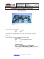
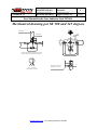
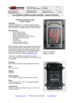
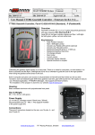
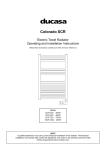
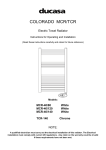
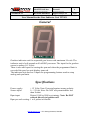
Documnent/File name
Document Type
MANTTT031E.doc
External
First Revision, Sign and Date
Updated Revision, Sign and Date
Document Status and Sign
Lan 2002-03-12
Rev.4 Bln 2004-02-11
Approved by Lan
Revision
4
Page
1 (6)
Document and Product Description
User Manual for the Gear Indicator Unit TTT031
General
Gearbox indicator unit for sequential gear boxes with maximum 9 levels. The
indicator unit is built around an 8 bit RISC processor. The input for the gearbox
sensor is analog (0-5 Volts).
There is also one input for sensing the rpm and when the programmed limit is
exceeded the gear box unit display turns red.
The indicator unit also has 2 inputs for programming buttons used to setup
analog and rpm limits.
Specifications
Power supply:
Sensor input:
+ 12 Volts, Note: Protected against wrong polarity.
0 – 5 Volts, Note: Do NOT use potentiometer less
than 1kohm.
Rpm input:
Digital, 1000 to 9900 revs/minute. Note: Do NOT
connect directly to ignition coil!
Rpm pre scale setting: 1 to 9 pulses/revolution
www.ttt-racing.com TTT Racing Products, Sweden.
Documnent/File name
Document Type
MANTTT031E.doc
External
First Revision, Sign and Date
Updated Revision, Sign and Date
Document Status and Sign
Lan 2002-03-12
Rev.4 Bln 2004-02-11
Approved by Lan
Revision
4
Page
2 (6)
Document and Product Description
User Manual for the Gear Indicator Unit TTT031
Connection
2 pole connector: Power supply
Red
+ 12 Volts
Black
Minus
3 pole connector: Programming buttons. Note: Only have these connected
during setup.
4 pole connector: Gear level potentiometer and rpm input
Potentiometer:
Blue
+ 5 Volts (Output from unit)
Brown
Signal
Black
Minus
Digital Rpm input:
Green
Rpm from ECU or ignition module
Note: Do NOT connect directly to ignition coil! If not
used, isolated or remove this cable from the connector
housing!!!
www.ttt-racing.com TTT Racing Products, Sweden.
Documnent/File name
Document Type
MANTTT031E.doc
External
First Revision, Sign and Date
Updated Revision, Sign and Date
Document Status and Sign
Lan 2002-03-12
Rev.4 Bln 2004-02-11
Approved by Lan
Revision
4
Page
3 (6)
Document and Product Description
User Manual for the Gear Indicator Unit TTT031
Setting up the unit
Programming gearbox levels:
Press the Black button, Level “r” and decimal point appears in green on
the display. Place the gearbox in the reverse, “r”, state then press the Red
button. This position is now saved in memory.
Now the display shows “0” and decimal point. Place the gearbox in
neutral position then press the Red button to save this position to
memory.
Now the display shows “1” and decimal point. Place the gearbox in first
gear position then press the Red button to save this position to memory.
Now the display shows “2” and decimal point….. Repeat until position
for all gears is saved in memory.
Press the Black button to exit programming mode.
Programming the rpm limit for the display to turn from green to red:
Press the Red button, the display now shows the rpm limit value x1000 in
red. Then press the Black button until the wanted x1000 value appears on
the display. Press the Red button to save this value in memory.
The display now shows the rpm limit value x100 in red. Then press the
Black button until the wanted x100 value appears on the display. Press
the Red button to save this value in memory.
The display now shows the number of pulses/revolution and the decimal
point. Press the Black button until the wanted value appears on the
display. Use 2 for four cylinder motor, 3 for six cylinder motor and 4 for
eight cylinder motor. Press the Red button to save this value in memory
and exit the programming mode.
Note: Disconnect the programming buttons after programming is
done!
www.ttt-racing.com TTT Racing Products, Sweden.
Documnent/File name
Document Type
MANTTT031E.doc
External
First Revision, Sign and Date
Updated Revision, Sign and Date
Document Status and Sign
Lan 2002-03-12
Rev.4 Bln 2004-02-11
Approved by Lan
Revision
4
Page
4 (6)
Document and Product Description
User Manual for the Gear Indicator Unit TTT031
Potentiometer assembly directions for 5 geared
Tractive gearbox.
308 or 345 degrees potentiometer.
Place the gearbox in the 2nd gear.
Adjust the plunch so that the groove is in 90 degree angle towards an
imaginary line between the fastening holes for the potentiometer.
Before the potentiometer is put in place its shaft should be rotated so the
mark on the shaft points at the connecting cable.
Assembly the potentiometer onto the gearbox and make sure that the
screws are centered in the potentiometers mounting holes.
Connect the display and turn on the power.
Measure with a digital voltmeter between the blue (+) and the black (-)
wire in the 4-pole connector on the display unit. Write down the reading.
(Should be approximate 5 Volt).
Then measure between the brown (Signal) and the black (-).
Adjust by turning the potentiometer so that this reading is as close as
possible to half of the first measurement.
Tighten the fastening screws.
Check by measuring again that tightening the screws did not affect the
potentiometers position.
The potentiometer is now in the right position and you can proceed with
the setup of the display unit.
Good luck.
www.ttt-racing.com TTT Racing Products, Sweden.
Documnent/File name
Document Type
MANTTT031E.doc
External
First Revision, Sign and Date
Updated Revision, Sign and Date
Document Status and Sign
Lan 2002-03-12
Rev.4 Bln 2004-02-11
Approved by Lan
Revision
4
Page
5 (6)
Document and Product Description
User Manual for the Gear Indicator Unit TTT031
Potentiometer assembly directions for 6 geared
Tractive gearbox.
345 degrees potentiometer.
Place the gearbox in the reverse gear.
Adjust the plunch so that the groove is in 90 degree angle towards an
imaginary line between the fastening holes for the potentiometer. Then
turn the plunch 13 degrees ccw.
Before the potentiometer is put in place its shaft should be rotated so the
mark on the shaft points at the opposite side of the connecting cable.
Assembly the potentiometer onto the gearbox and make sure that the
screws are centered in the potentiometers mounting holes.
Connect the display and turn on the power.
Measure with a digital voltmeter between the brown (Signal) and the
black (-) wire in the 4-pole connector on the display unit.
Adjust by turning the potentiometer so that this reading is as close as
possible to 0.08 Volt.
Tighten the fastening screws.
Check by measuring again that tightening the screws did not affect the
potentiometers position.
Place the gearbox in the 6th gear.
Measure with a digital voltmeter between the brown (Signal) and the
black (-) wire in the 4-pole connector on the display unit and check that
the reading is between 4.5 and 5.1 volts.
The potentiometer is now in the right position and you can proceed with
the setup of the display unit.
Good luck.
www.ttt-racing.com TTT Racing Products, Sweden.
Documnent/File name
Document Type
Revision
MANTTT031E.doc
External
First Revision, Sign and Date
Updated Revision, Sign and Date
Document Status and Sign
Lan 2002-03-12
Rev.4 Bln 2004-02-11
Approved by Lan
4
Page
6 (6)
Document and Product Description
User Manual for the Gear Indicator Unit TTT031
Mechanical drawing pot 5K 308 and 345 degrees
Centering-Ø10
-0.03
Ø4.5
3.5
17
+2
Ø16
Ø20°
7
7.2
Shaft marking
Ø28 -0.2
3
When the shaft marking is pointing to terminal 2 (red),
the wiper is located in an electrical center position.
2
1
>7.5
Ø38
Ø48
3 H11
1
2
3
brown red orange
Schematic view on the shaft
Dimensions of driving side
parallel offset < 0.05 mm.
www.ttt-racing.com TTT Racing Products, Sweden.
Ø>6