1
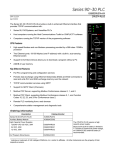
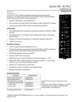
GFK-2123E July 22, 2003 IMPORTANT PRODUCT INFORMATION READ THIS INFORMATION FIRST Product: IC693CPU374 CPU Module with Ethernet Interface IC693CPU374-BF (and later) with CPU Firmware Release 11.04 This document contains information that is not available in any other publication; therefore, we recommend you save it for future reference. This release of the Series 90™-30 PLC CPU374 makes the following changes to the CPU firmware. There are no changes to the Ethernet daughter board firmware or the hardware. The following problems are corrected by this upgrade (for details see page 6): ■ Corrects the problem “Configurable Reference Tables Filled with Random Values after Size Change.” Hardware Identification The following table shows the revision level of the circuit boards used in this version of the IC693CPU374. CPU Model (Version) Circuit Board ID IC693CPU374-BF and later CY3A1 (CPU) E35A1 (Ethernet) Firmware Identification CPU Catalog Number IC693CPU374-BE and later Note: CPU Firmware Main: 11.04 (29A1) Boot: 11.00 (10A2) Revision Ethernet Daughterboard Firmware Main: 1.01 (20A1) Boot: 1.00 (15A2) The new firmware is compatible with all previous firmware and hardware versions of the IC693CPU374. Firmware Upgrade To upgrade a CPU374 to the latest firmware version (11.04), you must purchase the field upgrade kit 44A751579-G04 or download it at no charge from the web (http://www.gefanuc.com/support/plc/rs9030.htm). Firmware upgrades require the IC690ACC901 Miniconverter and Cable Kit. Documentation GFK- 0356, Installation and Hardware Manual GFK-0467, PLC CPU Instruction Set Reference Manual GFK-1541, TCP/IP Ethernet Communications for the Series 90 PLC User’s Manual, GFK-1186, TCP/IP Ethernet Communications for the Series 90 PLC Station Manager Manual 2 Important Product Information GFK-2123E CPU Operational Notes Battery Backup Limitations The battery on the CPU374 has an expected life of 1.2 months, if used continuously. If a longer battery backup period is required, the external battery module (IC693ACC302) is available. The extended battery module provides a battery backup period of 15 months for the CPU374. For additional information, see the External Battery Pack datasheet, GFK-2124. Overrides Not Stored to Flash or EZ Program Store Device When storing reference data to flash or the EZ Program Store Device, overrides are not stored. This means that after the reference data is read back from flash or the EZ Program Store Device and subsequently the PLC is put into Run Mode, the logic may execute differently. Therefore, overrides should not be used if reference data is stored to flash or to the EZ Program Store Device. If overrides are used, particular care should be taken to prevent loading reference data from flash at power up. If this precaution is not observed, unexpected operation may occur upon power cycle. Writing Flash Using a Serial Programmer When writing very large programs to flash memory, you may need to increase the request timeout value in the programming software to avoid receiving a request timeout message. An upper bound of 25 seconds is typically satisfactory. For further details, see the item “Store of Program or Reference Tables to Flash may Cause Loss of Ethernet Communications” in “Ethernet Operational Notes” on page 3. Storing Large Configurations The IC693CPU374 PLC supports a maximum of 20 DSM314 modules in a system. This number is reduced by other modules in the system, such as APM and GBC modules. It can also be further reduced by having datagrams set up to read the reference or fault tables. If the configuration and user program are stored at the same time, the presence of either C blocks within the LD program, or a C logic program also affects the number of DSM314 modules that can be included in a system. If the store fails, it may be possible to store the configuration to the system by first storing the logic program, and then storing the configuration on a separate store request. The number of modules supported is further reduced by the memory available to the user. Simultaneous Load and Store When operating with multiple programmers attached, if a store operation is initiated by one programmer while a load operation is already in progress, the load request will fail. Transition Tables are not Cleared when the Reference Tables are Cleared The transition tables are not cleared upon clearing the reference tables through the programmer. Upgrading Firmware with Modules in Rack The process of upgrading the PLC firmware with the WinLoader utility may fail when multiple IO modules are in the main, remote or expansion racks, due to the time it takes to power cycle the PLC. If the upgrade process fails, move the PLC to a rack without IO modules and restart the upgrade process. PID Integral Contribution The PID Integral Contribution is not calculated correctly with an integral rate of zero or one. Important Product Information 3 GFK-2123E Ethernet Operational Notes Configuration of IP Address is Required Before Using Ethernet Communications The Ethernet interface within the CPU module cannot operate on a network until a valid IP address is configured. The necessary Ethernet addressing information must be configured prior to actual network operation. Use one of the following methods: ■ Perform the initial configuration using a PLC Programmer connected through the PLC power supply serial port. ■ Connect a serial terminal to the station manager port of the CPU374. Then use the CHSOSW command to enter a temporary IP address. The Ethernet Interface can then be accessed over the network (such as by an Ethernet PLC Programmer). For details, see the TCP/IP Ethernet Communications for the Series 90 PLC Station Manager Manual, GFK-1186. ■ Temporarily assign an IP address to the module using the Ethernet network. For details, see the TCP/IP Ethernet Communications for the Series 90 PLC Station Manager Manual, GFK-1541, Appendix D. Proper IP Addressing is Always Essential The CPU374’s embedded Ethernet Interface must be configured with the correct IP Address for proper operation in a TCP/IP Ethernet network. Use of incorrect IP addresses can disrupt network operation for the CPU374 and for other nodes on the network. Refer to the TCP/IP Ethernet Communications for the Series 90 PLC User’s Manual for important information on IP addressing. Ethernet Programmer May Briefly Lose Communications When Configuration Stored Storing a PLC configuration containing Ethernet configuration values may require the Ethernet interface to restart itself in order to use any changed configuration values. When the Ethernet interface restarts, an Ethernet PLC Programmer briefly reports a loss of communications. If this occurs, the Ethernet Interface will post two or more PLC faults with the text “LAN system-software fault; resuming,” and fault-specific data starting with 080008 and/or 080042. In addition, faults with text “Bad remote application request; discarded request” (1B0021) and “Local request to send rejected; discarded request” (110005) may occur. When these faults occur, the STAT LED on the CPU374 is turned off to indicate posting of faults to the PLC fault tables. In some cases, a 10-second delay may occur before loss of communications is detected. Normal operation resumes once the Ethernet Interface restarts. The STAT LED can be reset using the Station Manager OK command. When the PLC configuration is stored from an Ethernet PLC Programmer, the communications loss occurs immediately after successful completion of the store. Attempts to store configuration plus logic and/or reference tables in one operation can fail. However, storing configuration separately from logic or reference tables always succeeds. Store of Program or Reference Tables to Flash May Cause Loss of Ethernet Communications While storing the PLC program, configuration, and/or reference tables from PLC RAM memory into Flash memory or to the EZ Program Store device, Ethernet data communications may be lost. Normal data transfers are temporarily suspended during a Flash or EZ Program Store device store operation. In these cases, Ethernet data transfers (such as used by an Ethernet PLC Programmer connection) will fail when the store exceeds the 16-second maximum period allowed for completion. Upon completion of the store operation, normal operation will resume. If a timeout occurs during a store to Flash or EZ Program Store device, the timeout value should be increased in the programming software being used. See the User’s Manual for the programming software for more details. 4 Important Product Information GFK-2123E Ethernet Flash Test Failure The Ethernet daughter board continually tests the integrity of its flash memory. In the extremely unlikely event that corrupted flash is detected, a “Module software corrupted; requesting reload” fault is posted to the PLC Fault table, and the daughter board enters firmware loader mode. However, attempting to reload the firmware always fails when a hard failure of a flash memory device has occurred. Invalid Ethernet Restart Event After power is applied, the restart event (event 1H) in the Ethernet Station Manager exception log may occasionally contain 000cH in entry 3, erroneously indicating that a time-out of the Ethernet watchdog timer occurred. This condition does not produce a PLC fault or turn off the Ethernet STAT LED, and it has no effect on subsequent operation. It is unlikely to occur when power supply IC693PWR321A or later is used. Note that an actual watchdog time-out produces a “Reset of daughter board” fault in the PLC Fault table. YATS32 SNTP Server Configuration Users of the YATS32 SNTP server should either configure the server for broadcast mode or multicast mode, but not for both. If the server is configured for both modes, two time messages will be sent to the PLC either simultaneously, or within a short period of time. TRACE Command Causes Ethernet Interface to Flash Error Code 3-1 or Restart Starting and stopping a Station Manager TRACE command repetitively may cause the CPU374 Ethernet Interface to halt and flash the error code 3-1 or to restart. First PING Response Lost after Restart of Ethernet Interface Immediately after restarting the Ethernet Interface, the first response to a PING large enough to require more than one IP packet (1466 bytes or larger) is not generated. Multiple Zero Period EGD Exchanges May Not Produce Similar Numbers of Samples If more than one EGD produced exchange is configured for a production period of zero, the exchanges may not produce similar numbers of samples. Due to the way that scheduling occurs when multiple exchanges are scheduled “as fast as possible,” some zero period exchanges may produce significantly more samples than others. EGD Performance Information Users requiring detailed EGD performance information should contact their Application Engineer and ask about the EGD Performance Application Note for the CPU374. Multicast Data Not Filtered The CPU374 does not do hardware filtering of multicast data over Ethernet. This means that extraneous multicast messages on the network add an additional load on the CPU374 PLC, and may significantly degrade performance. Sufficient load can cause the CPU374 to reset its communication processor. Changing IP Address While SRTP Connection Open May Generate Log Events SRTP connections established to the client are not terminated gracefully when the CPU374's IP address is changed. SRTP channels report either a 9690H or 0190H status, and possibly remain open until the connections are terminated as a result of client timeouts. Heavy Load Can Block Station Manager A heavy EGD or SRTP load can block Station Manager operation. Important Product Information 5 GFK-2123E CPU Functional Compatibility HHP Compatibility The CPU374 does not support the Hand Held Programmer. Programmer Version Requirements Control software version 2.50 or later, CIMPLICITY® Machine Edition Logic Developer 2.60 or later, or VersaPro 2.03 or later must be used to configure and program the CPU374. C Toolkit Compatibility Version 4.00 or later of the C toolkit must be used for C programming. IC693CMM321 Ethernet Option Module Version Requirements All Series 90-30 Ethernet Interface (IC693CMM321) modules used with this CPU should be updated to IC693CMM321 firmware release 1.10 or later. FBC Compatibility FIP Bus Controller version 3 or later is required for this CPU. Power Supply Compatibility and Requirements The CPU374 is compatible with any of the Series 90-30 power supplies, except Revisions A through J, Revision W, and Revision X of Power Supply IC693PWR321. If the IC693PWR321 is used, it must be Revision K through V, or Revision Y or later. • If a Release 11.01 or later CPU374 is used with Revision X or W of the IC693PWR321, it will always power up in a cleared state – Program, Configuration, Stored Values, Override Tables, and Fault Tables are all cleared. • If a Release 11.00 CPU374 is used with Revision X or W of the IC693PWR321, it may fail to power up properly, or may power up with a “Corrupted user memory” and/or a “Program block checksum failure” fault. A High Capacity Power Supply (IC693PWR330, IC693PWR331 or IC693PWR332) is strongly recommended. Power consumption of the CPU374 and its supporting devices are listed below: ■ CPU374 requires 1.48A @ +5VDC (= 7.4 Watts). ■ If used, the converter in the IC690ACC901 serial cable assembly requires 100mA at 5VDC (=0.5 Watts). ■ If used, the IC690ACC900 RS-422/RS-485 to RS-232 converter requires 170 mA at 5 VDC (=0.85 Watts). IC693ALG220/221 Analog Input Module Version Requirements 90-30 CPUs 35x/36x/37x are not compatible with versions F and earlier of the IC693ALG220/221 Analog Input Modules. Version G or later of the IC693ALG220/221 must be used with these CPUs. If a version F or earlier IC693ALG220/221 module is used with a 35x/36x/37x CPU, the %AI values reported by the module may exhibit erratic behavior. IC693PBM200 PROFIBUS Master Module Version Requirements All IC693PBM200 modules used with a CPU 374 MUST be updated to firmware version 1.16 or higher. IC693PBS201 PROFIBUS Slave Module Version Requirements All IC693PBS201 modules used with a CPU 374 MUST be updated to firmware version 1.28.1 or higher. Important Product Information 6 GFK-2123E Ethernet Functional Compatibility The following features on the CPU364 are not supported in the CPU374: ■ SRTP Channels (COMMREQs for Ethernet messages.) ■ Name Resolution ■ BOOTP ■ AAUI Port CPU Problems Resolved by this Upgrade Configurable Reference Tables Filled with Random Values after Size Change The configurable reference memory tables (%AI, %AQ, and %R) may be filled with random data values after storing a hardware configuration that changes any of their sizes to a non-default value. Open CPU Problems CPU Error if Larger Reference Memory Configuration Stored after Maximum Size Program This error occurs under the following conditions: First the user must store a very large program to the CPU such that only a small amount of user memory is left. Second, the user must store ONLY a configuration where the configurable memory sizes exceed the maximum memory, leaving the previous program in the CPU. The CPU will stop communicating and the OK LED will blink at a 50% duty cycle with a 1 second period. To remedy this situation, clear the CPU’s non-volatile memory by discharging the super-capacitor on the CPU. To do this, remove the module from the rack, remove the faceplate, disconnect any batteries connected to the CPU’s battery terminals, and short across the two pads labeled ”mem clr.” The “mem clr” pads are located opposite the first Ethernet connector (on the same board as the key switch). The “mem clr” pads must be continuously shorted for one to two minutes to ensure the super-capacitor is fully discharged and memory is cleared. Failure to short these pads for the proper amount of time may cause a partial discharge of the super-capacitor, which results in an incomplete memory clear. This can cause the CPU to power on with the same symptoms as listed above. If this occurs, repeat the memory clear procedure again. Recommended Operation: When working with very large programs and enlarging configurable memory, store both the hardware configuration and logic at the same time. CPU Cleared / Hardware Fault Received when Using EZ Program Store Device to Update RAM and Flash The user program, configuration, stored values, overrides, and fault tables are cleared and a “CPU Hardware Fault” is logged when the Memory Protect/Run Stop key switch is set to the “ON/RUN” position and the EZ Program Store Device is used to program the CPU if the “EZ Program Store” hardware configuration option is set to “RAM & FLASH.” CPU does not Revert to Backup Ethernet Configuration After Interrupted Store from EZ Program Store Device The CPU retains its current Ethernet configuration instead of reverting to the backup configuration when a push-button store from the EZ Program Store Device is interrupted. (The interruption can take multiple forms, however one example is disconnecting the EZ Program Store Device during the store.) Important Product Information 7 GFK-2123E Watchdog Timeout / CPU RAM Memory Cleared when Using C Blocks The user program, configuration, stored values, overrides, and fault tables are cleared and a “PLC watchdog timer timed out” fault is logged if a C Block compiled for hardware floating point (compiled using the mk3plc7.bat function) attempts a floating point divide by zero. (This problem does not occur if the C Block was compiled for software floating point using the mk3plc.bat function.) Power Supply Serial Port does not Respond to SNP/SNPX Requests The Power Supply Serial Port does not respond to SNP or SNPX requests including the break character if an attach message is received that is missing the last character before the BCC, or a message is received that has an invalid BCC or is corrupted so the calculated BCC doesn’t match the BCC specified in the message. Power to the CPU must be cycled to regain communications. Configurable Reference Tables Filled with Random Values after Size Change The configurable reference memory tables (%AI, %AQ, and %R) may be filled with random data values after storing a hardware configuration that changes any of their sizes to a non-default value. EZ Program Loader not able to Update OEM Protection Locked Machines A CPU 374 cannot be updated with the EZ Program Loader if the CPU has its OEM protection locked even if the EZ Program Loader has the OEM password programmed into it. 8 Important Product Information GFK-2123E Open Ethernet Problems Number of SRTP Requests Tallied May Vary When running multiple SRTP channels, the number of requests, as reported by the client and the server, may differ between the connections. Reporting of Duplicate IP Address The CPU374 does not log an exception or a fault in the PLC when it detects a duplicate IP address on the network (unlike the CPU364). The duplicate IP address is reported in the STAT F output only. TCP Connections May Remain Half-Open on CPU374 Server if Client is Lost If an SRTP client with open connections to a CPU374 server is power cycled or reset, the server’s TCP connection may remain open for a long time (until the TCP keep-alive timer expires) once the client is restarted and attempts to reopen the communication. If quick recovery of the connection is needed, the AUP for TCP keep alive should be used to adjust the keep alive timer down to the desired maximum time for holding open the broken connection. Large Number of IP Re-assembly Failures on Large PING Between CPU374s When sending PINGs large enough to require more than one IP packet (1466 bytes or larger), a larger number than expected of IP ReasmFai tallies will be seen on the client and a corresponding number of “no timely response” errors will be seen in the PING results. Large SRTP transfers do not exhibit the same behavior. EGD messages always fit in a single packet and thus are not subject to this kind of problem. REPP Does Not Save Results of Aborted PING The station manager REPP command does not retain the results of a PING that is aborted due to error. The PING results are reported when the PING is aborted, but subsequent REPP commands give the results of the last successfully terminated PING. STAT C Command Reports Invalid Rack/Slot Location The station manager STAT C command reports the CPU374 as being located in Rack 0 Slot 15 instead of Rack 0 Slot 1. Multiple Log Events The Ethernet interface sometimes generates multiple exception log events and PLC Fault Table entries when a single error condition occurs. Under repetitive error conditions, the exception log and/or PLC Fault Table can be completely filled with repetitive error messages. Intermittent SNTP Loss of Synchronization Under moderately heavy EGD traffic load, the Ethernet interface may occasionally lose synchronization with its SNTP time server and generate exception log event 29, entry 2=bH. Important Product Information GFK-2123E IC693CPU374 Data Controller Type Processor Processor Speed Processor Type Execution Time (Boolean Operation) Type of Memory Storage Memory User Memory (total) Discrete Input Points - %I Discrete Output Points - %Q Discrete Global Memory - %G Internal Coils - %M Output (Temporary) Coils - %T System Status References - %S Register Memory - %R Analog Inputs - %AI Analog Outputs - %AQ System Registers - %SR Timers/Counters Hardware Support Battery Backed Clock Battery Back Up (Number of months with no power) Load Required from Power Supply Hand Held Programmer EZ Program Store Device Total Baseplates per System Software Support Interrupt Support Communications and Programmable Coprocessor Compatibility Override Floating Point Math Programming Support Single slot CPU module with embedded Ethernet Interface 133 MHz Embedded 586 0.15 µsec per boolean instruction RAM and Flash 240KB (245,760) Bytes Note: Actual size of available user program memory depends on the amounts configured for %R, %AI, and %AQ configurable word memory types. 2,048 (fixed) 2,048 (fixed) 1,280 bits (fixed) 4,096 bits (fixed) 256 bits (fixed) 128 bits (%S, %SA, %SB, %SC - 32 bits each) (fixed) Configurable 128 to 32,640 words Configurable 128 to 32,640 words Configurable 128 to 32,640 words 28 words (fixed) >2,000 (depends on available user memory) Yes 1.2 months for internal battery (installed in the power supply) 15 months with external battery (IC693ACC302) 7.4 watts of 5VDC. High Capacity power supplies recommended. CPU374 does not support Hand Held Programmer Yes 8 (CPU baseplate + 7 expansion and/or remote) Supports the periodic subroutine feature. Yes Yes Yes, Hardware Floating Point Math VersaPro 2.03 or later. CIMPLICITY Machine Edition Logic Developer 2.60 or later. Control software version 2.50 or later. Communications Support Built-in Serial Ports No serial ports on CPU374. Supports RS-485 port on power supply. Protocol Support SNP and SNPX on power supply RS-485 port Built-in Ethernet Communications Ethernet (built-in) – 10/100 base-T/TX Ethernet Switch Number of Ethernet Ports Two, both are 10/100baseT/TX ports with auto sensing. RJ-45 connection Number of IP Addresses One Protocols SRTP and Ethernet Global Data (EGD). No channel support. Web Server Support None Environmental and Agency Specifications Operating Temperature 0 to 60°C (32 to 140°F) ambient Storage Temperature -40°C to +85°C Agency Approvals UL508, C-UL (Class I, DIV II, A, B, C, D), CE Mark Low Temperature (LT) Testing Yes. The CPU374 is available for -40° to 60°C operation. 9