1
Xuri™ Cell Expansion System W25
User Manual
Page intentionally left blank
Table of Contents
Table of Contents
1
Introduction ..........................................................................................................
1.1
1.2
1.3
2
8
10
11
System description ..............................................................................................
12
2.1
2.2
2.3
2.4
2.5
2.6
13
16
26
29
32
36
System overview ...................................................................................................................................
Xuri Cell Expansion System W25, rocker ...................................................................................
Xuri Cell Expansion W25 CBCU .......................................................................................................
Xuri Cell Expansion W25 Pump ......................................................................................................
Cellbag bioreactor ................................................................................................................................
UNICORN software overview ..........................................................................................................
2.6.1
2.6.2
3
General UNICORN operation .....................................................................................................
The UNICORN help .........................................................................................................................
37
38
The UNICORN software .......................................................................................
40
3.1
3.2
3.3
41
42
49
Administration ........................................................................................................................................
System control .......................................................................................................................................
Methods in UNICORN ..........................................................................................................................
3.3.1
3.3.2
3.3.3
3.3.4
3.3.5
3.3.6
3.3.7
3.4
Method editor ..................................................................................................................................
Method creation .............................................................................................................................
Work with methods .......................................................................................................................
Text instructions .............................................................................................................................
Save a method ................................................................................................................................
Scouting .............................................................................................................................................
Method queues ...............................................................................................................................
50
53
57
64
72
76
82
Evaluation in UNICORN ......................................................................................................................
86
3.4.1
3.4.2
3.4.3
3.4.4
3.4.5
3.4.6
4
7
Important user information .............................................................................................................
Important concepts .............................................................................................................................
User documentation ...........................................................................................................................
Evaluation .........................................................................................................................................
Open and view results. ................................................................................................................
Run documentation ......................................................................................................................
Generate and print a predefined report format ...............................................................
Create a new report format ......................................................................................................
Edit an existing report format ..................................................................................................
87
89
93
98
100
111
System control description ................................................................................
113
4.1
114
pH and DO measurement and control .......................................................................................
4.1.1
4.1.2
4.1.3
4.2
pH and DO measurement principles .....................................................................................
pH and DO reading .......................................................................................................................
pH and DO control principles ....................................................................................................
115
117
118
pH control .................................................................................................................................................
121
4.2.1
4.2.2
4.2.3
4.3
CO2 control mode ..........................................................................................................................
Acid/Base control mode ..............................................................................................................
pH control transition delays ......................................................................................................
122
124
127
DO control ................................................................................................................................................
128
4.3.1
4.3.2
O2 control mode .............................................................................................................................
Speed control mode ......................................................................................................................
Xuri Cell Expansion System W25 User Manual 29-0646-22 AA
129
131
3
Table of Contents
4.3.3
4.4
DO control transition delays ......................................................................................................
132
Media control ..........................................................................................................................................
133
4.4.1
4.4.2
4.4.3
4.4.4
Media addition ................................................................................................................................
Perfusion ............................................................................................................................................
Deviation alarm ..............................................................................................................................
Media control inactivation .........................................................................................................
134
135
139
140
Recommended operating conditions ..........................................................................................
System verification ..............................................................................................................................
141
144
Operation ..............................................................................................................
150
5.1
151
4.5
4.6
5
Prepare the system ..............................................................................................................................
5.1.1
5.1.2
5.1.3
5.1.4
5.1.5
5.2
5.3
5.4
Select tray and Cellbag bioreactor .........................................................................................
Prepare pH and DO sensors ......................................................................................................
Attach the Cellbag bioreactor ...................................................................................................
Prepare the pump ..........................................................................................................................
Connect gas to system ................................................................................................................
152
156
159
161
166
Start the system ....................................................................................................................................
Edit system properties ........................................................................................................................
Prepare cultivation ...............................................................................................................................
170
174
176
5.4.1
5.4.2
5.4.3
5.4.4
5.4.5
5.5
Start a run .........................................................................................................................................
Pre-culture preparation ...............................................................................................................
Final checks before cultivation .................................................................................................
Addition of culture medium .......................................................................................................
Equilibrate the culture medium ...............................................................................................
177
182
184
185
188
Perform cultivation ..............................................................................................................................
191
5.5.1
5.5.2
5.5.3
6
7
Inoculation ........................................................................................................................................
Monitor and control the cultivation ........................................................................................
End cultivation .................................................................................................................................
192
193
198
Maintenance .........................................................................................................
200
6.1
6.2
6.3
Calibrations .............................................................................................................................................
Pump calibration ...................................................................................................................................
Cleaning ....................................................................................................................................................
201
203
205
Troubleshooting ...................................................................................................
206
7.1
7.2
7.3
7.4
7.5
7.6
207
208
212
226
227
229
Xuri Cell Expansion System W25 ...................................................................................................
Xuri Cell Expansion System W25, rocker ...................................................................................
Xuri Cell Expansion W25 CBCU .......................................................................................................
Xuri Cell Expansion W25 Pump ......................................................................................................
Cellbag bioreactor ................................................................................................................................
Software problems ...............................................................................................................................
7.6.1
7.6.2
7.6.3
8
4
Troubleshooting Method editor ...............................................................................................
UNICORN System Control ...........................................................................................................
Troubleshooting Evaluation .......................................................................................................
230
232
235
Reference information ........................................................................................
236
8.1
8.2
237
238
System specifications .........................................................................................................................
Component specifications ................................................................................................................
Xuri Cell Expansion System W25 User Manual 29-0646-22 AA
Table of Contents
8.3
8.4
8.5
8.6
8.7
8.8
Client computer specifications .......................................................................................................
Xuri Cell Expansion W25 CBCU semi-wetted materials ......................................................
Chemical resistance ............................................................................................................................
Tubing and connectors ......................................................................................................................
Auto calibration .....................................................................................................................................
Control settings .....................................................................................................................................
8.8.1
8.8.2
8.8.3
8.8.4
8.8.5
8.8.6
8.8.7
8.8.8
8.8.9
8.8.10
8.8.11
242
244
245
246
247
248
Rocking control ...............................................................................................................................
Heating control ...............................................................................................................................
Gas flow control .............................................................................................................................
CO2 mix control ...............................................................................................................................
O2 mix control ..................................................................................................................................
Pump control ...................................................................................................................................
pH measurement ...........................................................................................................................
pH control ..........................................................................................................................................
DO measurement ...........................................................................................................................
DO control .........................................................................................................................................
Media control ...................................................................................................................................
249
252
254
256
258
260
265
268
276
279
284
Index .......................................................................................................................
287
Xuri Cell Expansion System W25 User Manual 29-0646-22 AA
5
Page intentionally left blank
1 Introduction
1
Introduction
Purpose of this manual
Xuri Cell Expansion System W25 User Manual provides you with instructions and information how to run Xuri Cell Expansion System W25. It also includes relevant guidance
for practical handling and maintenance of the system units.
Scope of this document
This manual covers Xuri Cell Expansion System W25, including the rocker, CBCU, pump,
UNICORN™ software and accessories.
In this chapter
This chapter includes important user information, intended use of the system, and lists
of important concepts and user documentation.
This chapter contains the following sections:
Section
1.1 Important user information
See page
8
1.2 Important concepts
10
1.3 User documentation
11
Xuri Cell Expansion System W25 User Manual 29-0646-22 AA
7
1 Introduction
1.1 Important user information
1.1
Important user information
Read this before operating Xuri
Cell Expansion System W25
All users must read the entire Xuri Cell Expansion System W25 Operating Instructions
before installing, operating, or maintaining the instrument. Always keep the Operating
Instructions at hand when operating Xuri Cell Expansion System W25.
Do not operate Xuri Cell Expansion System W25 in any other way than described in the
user documentation. Otherwise, you may be exposed to hazards that can lead to personal injury and you may cause damage to the equipment.
Intended use
Xuri Cell Expansion System W25 is intended to be used as laboratory and manufacturing
equipment for cell cultivation.
Prerequisites
In order to follow this manual and use the system in the intended manner, it is important
that:
8
•
you have a general understanding of how the client computer and Microsoft® Windows® operating systems work.
•
you are acquainted with the use of general laboratory equipment and with handling
of biological materials.
•
you have read and understood the Safety instructions chapter in the Operating
Instructions.
•
the system is installed according to the instructions in the Operating Instructions.
•
a user account has been created according to UNICORN Administration and Technical
manual.
Xuri Cell Expansion System W25 User Manual 29-0646-22 AA
1 Introduction
1.1 Important user information
Safety notices
This user documentation contains WARNINGS, CAUTIONS and NOTICES concerning the
safe use of the product. See definitions below.
Warnings
WARNING
WARNING indicates a hazardous situation which, if not avoided,
could result in death or serious injury. It is important not to proceed
until all stated conditions are met and clearly understood.
Cautions
CAUTION
CAUTION indicates a hazardous situation which, if not avoided,
could result in minor or moderate injury. It is important not to proceed until all stated conditions are met and clearly understood.
Notices
NOTICE
NOTICE indicates instructions that must be followed to avoid
damage to the product or other equipment.
Notes and tips
Note:
A note is used to indicate information that is important for trouble-free and
optimal use of the product.
Tip:
A tip contains useful information that can improve or optimize your procedures.
Xuri Cell Expansion System W25 User Manual 29-0646-22 AA
9
1 Introduction
1.2 Important concepts
1.2
Important concepts
The concepts and abbreviations used in this manual are explained in the table below.
Concept/
abbreviation
Explanation
Cellbag™ bioreactor
The disposable container in which the cells are cultured.
DO
Dissolved oxygen.
DO sensor
Optical sensor for measurement of dissolved oxygen. Attached on DO configured Cellbag bioreactors.
pH sensor
Optical sensor for pH measurement. Attached on pH configured Cellbag bioreactors.
CBCU
Xuri™ Cell Expansion System W25 Cellbag Control Unit
Refers to instrument labeled Xuri Cell Expansion W25 CBCU.
Control unit for gas mixing, pH and DO control.
10
Pump
Xuri™ Cell Expansion System W25 Pump
Refers to instrument labeled Xuri Cell Expansion W25 Pump.
Rocker
Xuri™ Cell Expansion System W25
Refers to instrument labeled Xuri Cell Expansion System W25
Bioreactor system
The entire system, including rocker, CBCU, and pump, together
with Cellbag bioreactor and filter heater.
UNICORN
The software used for controlling and monitoring the system.
Xuri Cell Expansion System W25 User Manual 29-0646-22 AA
1 Introduction
1.3 User documentation
1.3
User documentation
The table below describes the user documentation for Xuri Cell Expansion System W25,
which is available from the Help menu in UNICORN or on the user documentation CD.
Document
Main contents
Xuri Cell Expansion System
W25 Operating Instructions
Instructions needed to install, operate and maintain
Xuri Cell Expansion System W25 in a safe way. Includes basic UNICORN system control functions.
Xuri Cell Expansion System
W25 User Manual
Detailed system descriptions and instructions on
how to run, maintain and troubleshoot Xuri Cell
Expansion System W25. Includes UNICORN system
control functions, method creation and handling,
together with evaluation and presentation of data.
Xuri Cell Expansion System
W25 Cue Card
Brief instructions providing an overview of how to
run the system.
UNICORN Administration and
Technical manual
Overview and detailed description of network setup
and complete software installation. Administration
of UNICORN and the UNICORN database.
UNICORN Online Help
Dialog descriptions for UNICORN.
User Documentation CD
CD containing the listed manuals and translated
versions of Xuri Cell Expansion System W25
Operating Instructions.
Xuri Cell Expansion System W25 User Manual 29-0646-22 AA
11
2 System description
2
System description
In this chapter
This chapter gives an overview of Xuri Cell Expansion System W25 and describes the
different bioreactor system units.
This chapter contains the following sections:
Section
12
See page
2.1 System overview
13
2.2 Xuri Cell Expansion System W25, rocker
16
2.3 Xuri Cell Expansion W25 CBCU
26
2.4 Xuri Cell Expansion W25 Pump
29
2.5 Cellbag bioreactor
32
2.6 UNICORN software overview
36
Xuri Cell Expansion System W25 User Manual 29-0646-22 AA
2 System description
2.1 System overview
2.1
System overview
Introduction
Xuri Cell Expansion System W25 is intended for cell cultivation. A disposable Cellbag
bioreactor is placed on a rocker and filled with gas, partially filled with culture medium,
and inoculated with cells.
The cell culture volume range is 0.3 L to 25 L, and working volume may be expanded up
to 10 times during one cultivation. Gas transfer and mixing of culture is accomplished
by wave-induced agitation, performed by a rocker unit.
The system, composed of the rocker, CBCU and pump, enables measurement and control
of pH, DO, weight and media distribution, and provides different gas flow and gas mixing
possibilities.
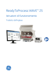
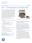
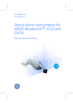
Illustration of the system
The illustration below shows the main bioreactor system units.
Part
Description
1
Hatch
2
Filter heater
3
Cellbag bioreactor
Xuri Cell Expansion System W25 User Manual 29-0646-22 AA
13
2 System description
2.1 System overview
Part
Description
4
Xuri Cell Expansion W25 Pump
5
Xuri Cell Expansion W25 CBCU
6
Xuri Cell Expansion System W25, rocker
7
Tray
8
Lid
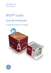
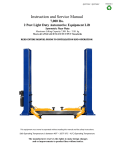
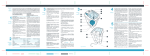
Illustration of wave motion
1
2
4
3
14
Stage
Description
1
Inflowing gas from the CBCU enters the Cellbag bioreactor through the
inlet gas filter. The gas flow inflates the bag and oxygenates the culture.
2
Metabolic waste gases leave the Cellbag bioreactor through the outlet gas
filter. The pressure control valve maintains a constant overpressure inside
the Cellbag bioreactor.
3
The rocking mechanism sets the rocking platform in motion.
4
Wave motions are induced by the rocking. The culture is cautiously mixed,
and gases are transferred into the culture.
Xuri Cell Expansion System W25 User Manual 29-0646-22 AA
2 System description
2.1 System overview
Available control parameters
The table below describes the control parameters for the fully configured bioreactor
system. The control parameters of your configuration may vary from the list below.
Control of
Description
Temperature
The system has a capacity to control temperature between room
temperature plus 5°C and 40°C.
Rocking speed
Rocking speed can be set between 2 and 40 rpm.
Rocking angle
Rocking angle can be set between 2 and 12 degrees.
Rocking motion
Rocking motion can be set between 15% and 100%, and is by default set to 30%. A rocking motion of 15% gives a uniform motion
with almost constant angular velocity throughout the movement,
and 100% gives a smooth, completely sinusoidal motion.
Gas flow
The system has a capacity to control the gas flow into the cellbag
between 0.02 and 1.00 lpm.
Media distribution
The system has a capacity to control culture medium addition and
removal. Two different modes exist, media addition and perfusion.
pH
pH is measured and controlled between pH 6 and pH 8. Three different modes of pH regulation exist, with CO2, CO2/base, and
acid/base.
DO
DO is measured between 0% and 250% and controlled between
0% and 100% air saturation. Three different modes of DO regulation
exist, with O2, speed, and O2/speed.
CO2
CO2 concentration in gas mix can be controlled between 0% and
15% and measured between 0% and 20%.
O2
O2 concentration in gas mix can be measured between 0% and
50%, and controlled between 0% and 50% with N2 and between
21% and 50% with air.
Xuri Cell Expansion System W25 User Manual 29-0646-22 AA
15
2 System description
2.2 Xuri Cell Expansion System W25, rocker
2.2
Xuri Cell Expansion System W25, rocker
Introduction
The rocker is the main unit of the system. Through the rocker, weight is measured, and
temperature, rocking speed, rocking angle and rocking motion are controlled. The
rocker contains an embedded computer, which allows running the system independently
of the performance of the connected network and client computer.
The dimensions and weight of the rocker are listed in Section8.2 Component specifications,
on page 238.
Rocking parameters
The adjustable rocking parameters are rocking speed, rocking angle and rocking motion.
These factors, in combination with the cell culture volume have a direct impact on the
oxygen transfer rate and mixing time in the Cellbag bioreactor.
The rocking motion sets how large part of the rocking cycle that has a sinusoidal angular
velocity. It can be adjusted to be more or less sinusoidal. The minimum value, 15%, gives
a uniform motion with almost constant angular velocity throughout the movement, resulting in a step-wise rocking. The maximum value, 100%, gives a sinusoidal motion with
slower angular velocity in the end positions and faster in the middle of the movement,
resulting in a smoother rocking.
16
Xuri Cell Expansion System W25 User Manual 29-0646-22 AA
2 System description
2.2 Xuri Cell Expansion System W25, rocker
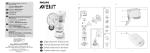
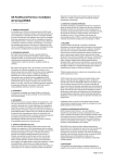
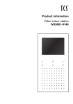
Front view of the rocker
The illustration below shows the front view of the rocker.
Xuri TM Cell
Expansio
n System
W25
Part
Description
1
Rocker platform
2
Temperature sensors
3
Rocker base
4
Power switch
5
Location of adjustable foot
Power switch
The power switch indicates the status of the rocker according to the list below.
Light indicator
Description
No light
The power is off.
Green blinking light
The rocker is starting up.
Green steady light
The power is on and the rocker is operational.
Xuri Cell Expansion System W25 User Manual 29-0646-22 AA
17
2 System description
2.2 Xuri Cell Expansion System W25, rocker
Light indicator
Description
Red blinking light
The rocker failed to connect to the system.
Red steady light
Indicates an error of the rocker.
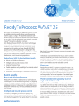
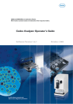
Adjustable foot
The adjustable foot is placed in the front right corner of the rocker when viewed from
the front. It is used to evenly distribute weight over the four rocker feet.
To adjust the foot, remove the side plate, carefully lift the front right corner of the rocker
and turn the foot by hand.
In the image below, the rocker is shown without a side plate in order to display the adjustable foot.
18
Xuri Cell Expansion System W25 User Manual 29-0646-22 AA
2 System description
2.2 Xuri Cell Expansion System W25, rocker
Rear view of the rocker
The illustration below shows the rear panel of the rocker.
1
2
Part
Description
1
15-pin D-sub connector
2
Filter heater connectors
3
UniNet-9 ports
4
USB ports
5
Ethernet connector
6
Power connector
Xuri Cell Expansion System W25 User Manual 29-0646-22 AA
3
4 5
6
19
2 System description
2.2 Xuri Cell Expansion System W25, rocker
Tray and lid sizes
Trays and lids are available in the different sizes listed below:
Trays
Lids
Tray 10
Lid 10
Tray 20
Lid 20
Tray 50
Lid 50
Illustrations of tray and lid
The illustration below shows the rocker with Tray 50 attached.
1
Xu
ri™
Ce
ll Exp
an
2
sio
n Sys
tem
W2
5
4
3
Part
Description
1
Bag clamp (upper)
2
Bag clamp opener (one in each upper corner)
3
Bag clamp opener (one in each lower corner)
4
Bag clamp (lower)
The illustration below shows the rocker with Tray 50 and Lid 50 mounted.
20
Xuri Cell Expansion System W25 User Manual 29-0646-22 AA
2 System description
2.2 Xuri Cell Expansion System W25, rocker
4
5
3
2
Xuri™
Cel
l Ex
pans
ion
Syste
mW
25
1
Part
Description
1
Rocker base
2
Lid
3
Tray
4
Tubing exit
5
Hatch
Xuri Cell Expansion System W25 User Manual 29-0646-22 AA
21
2 System description
2.2 Xuri Cell Expansion System W25, rocker
The illustration below shows the rocker with Tray 10 and Lid 10 mounted.
Xuri™
Cel
l Ex
pans
ion
Syste
mW
25
22
Xuri Cell Expansion System W25 User Manual 29-0646-22 AA
2 System description
2.2 Xuri Cell Expansion System W25, rocker
Prepare for tilt
When the system enters END mode, the tray prepares for tilt by default. It can be changed
in System Settings:Rocker:Prepare for tilt at END. This position is the mechanical end
position of the rocker, which is 14 degrees. This position can also be set by executing
the manual instruction Rocker:Prepare for tilt. See illustration below.
Xuri™
Cell Expan
sion Syste
m W25
Tilt position
In order to facilitate sampling and harvest, it is possible to position the tray with the attached Cellbag bioreactor into an upright position called tilt position.
For visibility purposes the tray is shown without the Cellbag bioreactor attached in the
images below.
Step
Action
1
Select the largest possible angle in UNICORN, i.e., 12 degrees, or prepare for
tilt as described above.
Xuri Cell Expansion System W25 User Manual 29-0646-22 AA
23
2 System description
2.2 Xuri Cell Expansion System W25, rocker
Step
Action
2
Grab the textured grip area on each side of the tray and pull the tray towards
you.
Xuri™
Cell Expansi
on System
W25
The illustration below shows the tilt position:
Xuri™
Cell
Expa
nsion
Syste
m W25
24
Xuri Cell Expansion System W25 User Manual 29-0646-22 AA
2 System description
2.2 Xuri Cell Expansion System W25, rocker
Illustration of filter heater
The filter heater prevents occurrence of condensation and clogging of the outlet gas
filter of the Cellbag bioreactor.
1
2
3
Part
Description
1
Filter heater
2
Connector for connection to the rocker
3
Filter heater stand
Xuri Cell Expansion System W25 User Manual 29-0646-22 AA
25
2 System description
2.3 Xuri Cell Expansion W25 CBCU
2.3
Xuri Cell Expansion W25 CBCU
Introduction
The control unit, Xuri Cell Expansion W25 CBCU, is connected to the rocker via a UniNet9 connector. The full configuration mixes air/N2, O2, and CO2 gas, and contains O2 and
CO2 sensors, a mass flow controller, an optical pH sensor reader, and an optical DO
sensor reader. Three configurations are available:
•
CO2, O2 and pH.
•
CO2, O2 and DO.
•
CO2, O2, pH and DO, full configuration.
The dimensions and weight of the CBCU are listed in Section 8.2 Component specifications,
on page 238.
Front view of Xuri Cell Expansion
W25 CBCU
The illustration below shows the front panel of a fully configured CBCU. The configuration
of your CBCU may vary from the configuration shown below.
Xuri™ Cell Expansion W25 CBCU
1
26
2
3
4
Xuri Cell Expansion System W25 User Manual 29-0646-22 AA
2 System description
2.3 Xuri Cell Expansion W25 CBCU
Part
Component
Description
1
pH port
Connector for pH sensor fiber cable.
2
GAS MIX OUT
Gas outlet for connection to Cellbag bioreactor.
3
Status LED
Indicates the CBCU operating status.
4
DO port
Connector for DO sensor fiber cable.
Status LED
The status LED indicates the CBCU operating status according to the following table.
Light indicator
Description
Steady green light
The CBCU is ready for operation.
Green blinking light
The CBCU is operating.
Red blinking light
Indicates an internal error, but the CBCU is still operating.
Steady red light
Indicates an internal error, and the CBCU is not operating.
Rear view of Xuri Cell Expansion
W25 CBCU
The illustration below shows the rear panel of a fully configured CBCU.
Xuri Cell Expansion System W25 User Manual 29-0646-22 AA
27
2 System description
2.3 Xuri Cell Expansion W25 CBCU
Part
Component
Description
1
UniNet-9 port
Power connection to the rocker.
2
CAN indicator LED
Indicates system connection status.
3
CAN ID switch
Switch for setting the CBCU unit number for system
recognition.
4
O2 IN
Inlet connection for O2 supply.
5
CO2 IN
Inlet connection for CO2 supply.
6
AIR/N2
Inlet connection for air or N2 supply.
CAN ID
The CAN ID is a unit number used by UNICORN to recognize that the CBCU is connected
to the system.
The CAN ID is set by turning a switch on the CBCU rear panel (see illustration above).
Two possible CAN ID positions are available on the switch, marked 1 and 2, respectively.
The CAN ID should always be set to position 1.
28
Xuri Cell Expansion System W25 User Manual 29-0646-22 AA
2 System description
2.4 Xuri Cell Expansion W25 Pump
2.4
Xuri Cell Expansion W25 Pump
Introduction
Xuri Cell Expansion W25 Pump is a peristaltic pump unit that includes two roller pumps.
It pumps fluid for feed, harvest/waste, and pH control with acid and base.
The dimensions and weight of the pump are listed in Section8.2 Component specifications,
on page 238.
Front view of the pump
The illustration below shows the front panel of the pump.
XuriTM Cell Expansion W25 Pump
ACID
BASE
FEED
HARVEST
WASTE
Part
Description
1
Pumphead flip top
2
Pumphead
3
Status LEDs for pumping function per pumphead
Xuri Cell Expansion System W25 User Manual 29-0646-22 AA
29
2 System description
2.4 Xuri Cell Expansion W25 Pump
Status LEDs
The status LEDs indicate the pumping function status according to the following table.
Light indicator
Description
Steady green light
The pumping function is ready for operation.
Green blinking light
Pumping is ongoing.
Red blinking light
Indicates an internal error, but the pump is still operating.
Steady red light
Indicates an internal error, and the pump is not operating
properly.
Rear view of the pump
The illustration below shows the rear panel of the pump.
30
Part
Component
Description
1
UniNet-9 port
Power connection to the rocker.
2
CAN indicator LED
Indicates system connection status.
3
CAN ID switch
Shows the unit number of the pump for recognition
by the system.
Xuri Cell Expansion System W25 User Manual 29-0646-22 AA
2 System description
2.4 Xuri Cell Expansion W25 Pump
CAN ID
The CAN ID is a unit number used by UNICORN to recognize the particular pump unit
that is connected. If more than one pump unit is connected, the units are distinguished
by their CAN IDs.
The CAN ID is set by turning a switch on the pump rear panel (see illustration above).
Four possible CAN ID positions are available on the switch, marked 1, 2, 3, and 4, respectively. The CAN ID should be set to position 1 for the first pump and to position 2 for the
second pump.
Xuri Cell Expansion System W25 User Manual 29-0646-22 AA
31
2 System description
2.5 Cellbag bioreactor
2.5
Cellbag bioreactor
Introduction
Cell cultivation is performed inside the Cellbag bioreactor. The Cellbag bioreactor is delivered gamma irradiated and ready for use. It is intended for single use only and must
be discarded after use.
Cellbag bioreactor options
The Cellbag bioreactors are available in different configurations, of varying sizes and
equipped with various ports. Cellbag bioreactors with internal cell retention filters are
available for perfusion culture. If required, it is possible to customize the Cellbag bioreactors. The following bag sizes are available for Xuri Cell Expansion System W25:
32
•
2L
•
10 L
•
20 L
•
22 L
•
50 L
Xuri Cell Expansion System W25 User Manual 29-0646-22 AA
2 System description
2.5 Cellbag bioreactor
Illustration of Cellbag bioreactor
The illustration shows a general Cellbag bioreactor. The configuration of your Cellbag
bioreactor may vary from the configuration shown below.
1
2
3
9
4
8
5
7
6
Part
Component
Description
1
pH bag sensor
port
The pH bag sensor port is located on the
underside of the bag. Holds a sensor for
online pH control of the cell culture.
2
Outlet gas filter
with pressure
control valve
The filter prevents airborne particles of 0.2
micron or larger to enter the bag.
3
Inlet gas filter
The filter removes airborne particles of 0.2
micron or larger from the gas flow before
it enters the Cellbag bioreactor.
4
Addition port
Addition port equipped with a Luer quick
connector.
5
DO bag sensor
port
The DO bag sensor is located on the underside of the bag. Holds a sensor for online
dissolved oxygen control of the cell culture.
6
Cellbag rod
The Cellbag rod fixes the Cellbag bioreactor
to the tray.
Xuri Cell Expansion System W25 User Manual 29-0646-22 AA
The pressure control valve maintains a
constant overpressure inside the Cellbag
bioreactor.
33
2 System description
2.5 Cellbag bioreactor
Part
Component
Description
7
CLAVE™ sampling port
Sampling port equipped with a self-sealing
luer fitting.
8
Addition port
Addition port equipped with a Luer quick
connector.
9
Addition/harvest
port
Addition/harvest port equipped with a MPC
quick connector.
pH and DO sensors
The Cellbag bioreactor may be equipped with optical sensors for monitoring of pH and
dissolved oxygen (DO). The sensors are light sensitive and should therefore be protected
from excessive light. The sensors are located in the center of a sensor port on the Cellbag
bioreactor and must be coupled to a sensor adapter, see table below.
Part
Description
Bag sensor
port
The sensor port is located on the underside of the Cellbag bioreactor.
The actual sensor (white for pH, pink/black for DO) is located in the
center (1) of the sensor port, see image below.
The sensor adapter is attached to the sensor port by the four pins (2).
1
2
34
Xuri Cell Expansion System W25 User Manual 29-0646-22 AA
2 System description
2.5 Cellbag bioreactor
Part
Description
Sensor
adapter
The sensor adapter is located at one end of an optical fiber cable.
The optical lens of the fiber cable is located in the center of the sensor
adapter. The fiber cable is connected to a sensor reader in the CBCU.
The fiber cable is connected to the pH or DO port on the CBCU front
panel.
Xuri Cell Expansion System W25 User Manual 29-0646-22 AA
35
2 System description
2.6 UNICORN software overview
2.6
UNICORN software overview
In this section
This section gives an overview of the general operation of the UNICORN software: a
complete package for control, supervision and evaluation of cell cultivation runs. It also
describes how to access the help utility that is included in UNICORN. Refer to Chapter 3
The UNICORN software, on page 40 for more information.
This section contains the following subsections:
Section
36
See page
2.6.1 General UNICORN operation
37
2.6.2 The UNICORN help
38
Xuri Cell Expansion System W25 User Manual 29-0646-22 AA
2 System description
2.6 UNICORN software overview
2.6.1 General UNICORN operation
2.6.1
General UNICORN operation
UNICORN modules overview
UNICORN consists of four modules: System Control, Evaluation, Administration and
Method Editor.
The main functions of each module are described in the table below.
Module
Main functions
Method Editor
Create and edit methods.
System Control
Start, view and control runs.
Evaluation
Open results, evaluate runs and create reports.
Administration
Perform user and system setup, system log and database
administration.
Enter a UNICORN module
To enter a module:
•
click the Taskbar button of the module of interest,
or
•
choose the module of interest in the Tools menu in any of the other software modules.
The illustration below shows the Tools menu of the Evaluation module.
Xuri Cell Expansion System W25 User Manual 29-0646-22 AA
37
2 System description
2.6 UNICORN software overview
2.6.2 The UNICORN help
2.6.2
The UNICORN help
Access the help utility
A comprehensive help utility is included in the UNICORN software. The table below describes how to access the different parts of the help utility.
If you want to...
then...
find information about
a UNICORN module
select Help:Help for... in the UNICORN module of interest
find information about
the item currently selected and in focus (e.g., a
pane, a dialog, or a
method phase)
•
•
click the Help icon in the open dialog
navigate the online help
•
select Help:Help for... in any of the UNICORN modules
(see illustration above)
•
in the TOC (Table of contents) pane, expand the
headings of interest to navigate the content structure
•
click the heading of interest to open a section
•
select Help:Help for... in any of the UNICORN modules
(see illustration above)
•
in the Search pane, enter the term of interest in the
input field
•
click the Search button
search for a specific
term in the online help
38
press the F1 key with the item of interest selected and
in focus
or
Xuri Cell Expansion System W25 User Manual 29-0646-22 AA
2 System description
2.6 UNICORN software overview
2.6.2 The UNICORN help
If you want to...
then...
access manuals in PDF
format
•
select Help:Help for... in any of the UNICORN modules
(see illustration above)
•
in the TOC pane, expand the heading UNICORN online
documentation portal and select Documentation
overview
•
in the PDF manuals section, click one of the text links
find information about
an instruction
In the Method Editor module:
•
open a method
•
select the instruction of interest in the Instruction box
in the Text instruction pane
•
press the F1 key
In the System Control module:
•
select Manual:Execute Manual Instructions
•
expand a heading and select the instruction of interest
•
press the F1 key
or
click the Help icon in the dialog
Xuri Cell Expansion System W25 User Manual 29-0646-22 AA
39
3 The UNICORN software
3
The UNICORN software
In this chapter
This chapter gives an overview of how to work with the four UNICORN modules. Detailed
information about the UNICORN software is available in the
UNICORN user documentation and in the UNICORN Online Help.
This chapter contains the following sections:
Section
40
See page
3.1 Administration
41
3.2 System control
42
3.3 Methods in UNICORN
49
3.4 Evaluation in UNICORN
86
Xuri Cell Expansion System W25 User Manual 29-0646-22 AA
3 The UNICORN software
3.1 Administration
3.1
Administration
Introduction
The Administration module is used to administer all functions of the UNICORN software.
Refer to UNICORN Administration and Technical manual for more information.
Icons in the Administration
module
The table below shows the Administration module icons.
Icon
Function
User Setup is used to administer the user access to UNICORN.
Access Groups and Network Users is used to administer access groups
and network users.
E-mail Setup is used to set up an e-mail account for automated system
messages.
UNICORN and System Log provides the system administrator with records
of usage and activity.
System Properties is used to define the system and edit system properties.
Database Management is used for maintenance of the database.
Xuri Cell Expansion System W25 User Manual 29-0646-22 AA
41
3 The UNICORN software
3.2 System control
3.2
System control
Introduction
The System Control module is used to start, view, and control a manual or a method
run.
System Control panes
As illustrated below, two tabs are available in the System Control module by default.
The Process Picture tab allows manual interactions with the system and provides
feedback on run parameters. Data is illustrated as curves in the Chart tab during the
entire run.
Refer to Section 5.5 Perform cultivation, on page 191 for information on how to perform
a run and to Section 5.5.2 Monitor and control the cultivation, on page 193 for information
on how to work with the Process Picture.
Tip:
42
To get more information than what is shown in the Process Picture, select
View:Run Data to open the Run Data pane which presents current data in
numerical values.
Xuri Cell Expansion System W25 User Manual 29-0646-22 AA
3 The UNICORN software
3.2 System control
Actions in the Process Picture
pane
It is possible to interact with the Process Picture pane in the following ways:
If you want to...
then...
activate or deactivate a
function
click on the right-hand side of the button.
Xuri Cell Expansion System W25 User Manual 29-0646-22 AA
43
3 The UNICORN software
3.2 System control
If you want to...
then...
open the settings for a
function
click on the left-hand side of the button.
The example below shows the settings for dissolved oxygen, DO.
adjust the settings
44
enter appropriate values in the Settings dialog and click
OK or press enter.
Xuri Cell Expansion System W25 User Manual 29-0646-22 AA
3 The UNICORN software
3.2 System control
System Control toolbar icons
The table below shows the System Control toolbar icons that are referred to in this User
Manual.
Icon
Function
Open Method Navigator: Opens the Method Navigator where available
methods are listed.
Run: Starts a method run.
Hold: Suspends the method run.
Continue: Resumes for example a held method run.
End: Permanently ends the method run.
Customize: Opens the Customize dialog where curve settings, run data
groups and run log contents can be set.
Connect to Systems: Opens the Connect to Systems dialog where systems
can be connected, and currently connected users are displayed.
Xuri Cell Expansion System W25 User Manual 29-0646-22 AA
45
3 The UNICORN software
3.2 System control
Curves
Monitor signals and instrument settings are shown in the chart as curves. The curves
are also saved in a result file, which can be opened in the Evaluation module. The default
view shows the most commonly used curves. The user may customize which curves to
display and the color and style of the displayed curves.
Note:
All curves are saved in the result file regardless of the curves displayed.
Note:
The complete ranges of the signals are saved in the result file regardless of
used factors, such as scaling and zooming, during the run.
The table below describes how to customize which curves to show in the chart. Refer to
the online help for further information about the tabs in the Customize dialog.
Step
Action
1
In the System Control module:
•
click the Customize icon
or
•
select Tools:Customize...
Result: The Customize dialog opens.
46
2
Select the Curves tab.
3
Select the checkboxes of the curves you want to show in the chart and then
click OK.
Xuri Cell Expansion System W25 User Manual 29-0646-22 AA
3 The UNICORN software
3.2 System control
System settings
Each installed instrument has a set of default parameter values, called system settings.
The System Settings dialog in System Control is used to view and edit the system setting
for the currently selected instrument before the run is started. Follow the instructions
below to change the System Settings. All available System Settings are described in
System Settings.
Step
Action
1
In the System Control module, select System:Settings.
Result: The System Settings dialog opens with the Instructions displayed.
See examples of different menus below.
2
Select the instruction to edit from the list. Click the + symbol to show the instructions for each category. The instructions in each category differ depending on the instrument configuration.
3
Select settings and choose parameter values for the selected instruction.
Click OK.
4
To return to the default values defined in the instrument configuration, click
Set Parameters To Strategy Default Values.
Manual instructions
It is possible to manually interact with an ongoing run using Manual instructions. Follow
the instructions below to perform manual instructions.
Note:
It is also possible to interact with the system manually directly from the Process
Picture.
Xuri Cell Expansion System W25 User Manual 29-0646-22 AA
47
3 The UNICORN software
3.2 System control
Step
Action
1
In the System Control module:
•
select Manual:Execute Manual Instructions
or
•
use the shortcut Ctrl +M.
Result: The Manual instructions dialog opens.
2
In the Manual instructions dialog:
3
•
Click the + symbol to show the instructions for the instruction group that
you want to modify.
•
Select the instruction that you want to modify.
•
Enter the new values for the instruction.
To execute several instructions at the same breakpoint, select and edit an
instruction and click Insert. Repeat for several instructions.
Note:
To update parameter fields during run, check the Auto update... box.
4
To perform the instructions, click Execute.
Run data
The Run Data pane shows the current values of for example rocking motion, pH measurement and accumulated time. Since there are many Run Data the view can be customized. To see more information, select View:Run Data and:
•
right-click in the Run Data pane and select Run Data Groups:Detailed
or
•
48
right-click and select Customize to customize the appearance of the Run Data pane.
Xuri Cell Expansion System W25 User Manual 29-0646-22 AA
3 The UNICORN software
3.3 Methods in UNICORN
3.3
Methods in UNICORN
In this section
This section describes how to create methods and work with predefined methods and
text instructions. For information about dialogs in the Method Editor that are not described in this manual, refer to the online help.
This section contains the following subsections:
Section
See page
3.3.1 Method editor
50
3.3.2 Method creation
53
3.3.3 Work with methods
57
3.3.4 Text instructions
64
3.3.5 Save a method
72
3.3.6 Scouting
76
3.3.7 Method queues
82
Xuri Cell Expansion System W25 User Manual 29-0646-22 AA
49
3 The UNICORN software
3.3 Methods in UNICORN
3.3.1 Method editor
3.3.1
Method editor
Introduction
In the UNICORN software, the instructions to control a bioreactor run can be defined in
a method. The Method Editor module is used to create or edit such methods.
User defined methods and
phases
A method is built up by a number of phases, and each phase is built up by a number of
instructions.
Refer to the UNICORN Online Help for more information about methods and phases and
how to create a method.
50
Xuri Cell Expansion System W25 User Manual 29-0646-22 AA
3 The UNICORN software
3.3 Methods in UNICORN
3.3.1 Method editor
Method Editor panes
As illustrated below, three panes are shown in the Method Editor by default. The available
User Defined phase is found in the Phase Library (1), and an overview of the phases included in the active method is displayed in a Method Outline (2). Information about the
method is presented in the right pane (3), containing the two tabs Phase Properties and
Text Instructions.
Method Editor toolbar icons
The table below shows the Method Editor toolbar icons that are referred to in this User
Manual.
Icon
Function
New Method: Opens the New Method dialog where methods can be created.
Open Method Navigator: Opens the Method Navigator where available
methods are listed.
Xuri Cell Expansion System W25 User Manual 29-0646-22 AA
51
3 The UNICORN software
3.3 Methods in UNICORN
3.3.1 Method editor
Icon
Function
Save: Saves the active method.
Print: Opens the Print dialog from where a method can be printed.
Start protocol: Opens the Start Protocol dialog, where settings for the
start protocol can be made.
Method notes: Opens the Method Notes dialog, where notes can be added
to the method.
Scouting: Opens the Scouting Variables dialog, which is used to repeat a
series of method runs.
New method queue: Opens the Method Queue dialog.
52
Xuri Cell Expansion System W25 User Manual 29-0646-22 AA
3 The UNICORN software
3.3 Methods in UNICORN
3.3.2 Method creation
3.3.2
Method creation
Predefined method
The table below describes how to create a new method using a predefined method as
template:
Step
Action
1
In the Method Editor:
•
click the Create a new method icon in the Toolbar
or
•
select File:New Method...
Result: The New Method dialog opens.
Xuri Cell Expansion System W25 User Manual 29-0646-22 AA
53
3 The UNICORN software
3.3 Methods in UNICORN
3.3.2 Method creation
Step
Action
2
In the New Method dialog:
•
select a System
•
select a Predefined Method
•
click OK
Result: The Method Outline pane shows the mandatory Method Settings
phase for the chosen method and the Text Instructions pane shows all the
instructions that defines the method. The Phase Properties pane shows the
default settings for the currently highlighted phase.
54
Xuri Cell Expansion System W25 User Manual 29-0646-22 AA
3 The UNICORN software
3.3 Methods in UNICORN
3.3.2 Method creation
Empty method
The table below describes how to create a new empty method:
Step
Action
1
In the Method Editor:
•
click the Create a new method icon in the Toolbar
or
•
select File:New Method...
Result: The New Method dialog opens.
Xuri Cell Expansion System W25 User Manual 29-0646-22 AA
55
3 The UNICORN software
3.3 Methods in UNICORN
3.3.2 Method creation
Step
Action
2
In the New Method dialog:
•
select a System
•
select the Empty Method radio button
•
click OK
Result: An empty method that consists of the mandatory Method Settings
phase is created.
56
Xuri Cell Expansion System W25 User Manual 29-0646-22 AA
3 The UNICORN software
3.3 Methods in UNICORN
3.3.3 Work with methods
3.3.3
Work with methods
Open method
The table below describes how to open an existing method in the database:
Step
Action
1
In the Method Editor:
•
Click the Open Method Navigator icon in the Toolbar
or
•
select File:Open...
or
•
select View:Method Navigator
Result: The Method Navigator is displayed.
Xuri Cell Expansion System W25 User Manual 29-0646-22 AA
57
3 The UNICORN software
3.3 Methods in UNICORN
3.3.3 Work with methods
Step
Action
2
Select the method to be opened in the Folder name column.
3
To open the method,
•
Click the Open button located in the toolbar of the Method Navigator
pane
or
•
double-click the selected method
or
•
Right-click on the method name and select Open from the context menu
Result: The method is opened and displayed in the Method Outline pane
with included phases. You can continue to edit the phases of the method
using Phase Properties, or manually text edit the method in the Text Instructions pane".
58
Xuri Cell Expansion System W25 User Manual 29-0646-22 AA
3 The UNICORN software
3.3 Methods in UNICORN
3.3.3 Work with methods
Add a user defined phase to the
method outline using
drag-and-drop
The table below describes how to add a user defined phase to the method outline using
drag-and-drop:
Step
Action
1
Select the User Defined phase in the Phase Library pane and drag-anddrop the phase to the requested position in the Method Outline pane.
Result: The phase is included in the method at the requested position.
2
When the User Defined phase has been added to the Method Outline, the
phase name is enabled for editing.
Type a name for the phase and press the Return keyboard key.
Note:
The User Defined phase is marked with the letter T, meaning that it is text
edited. This phase contains only Base and End_Block instructions, so any
functional instructions must be added by hand. To include instructions for the
User Defined phase, select the Text Instructions tab. The Phase Properties
tab will only show the variables used in this phase. See Section 3.3.4 Text instructions, on page 64 for information about how to work with instructions
in the Text Instructions pane.
Xuri Cell Expansion System W25 User Manual 29-0646-22 AA
59
3 The UNICORN software
3.3 Methods in UNICORN
3.3.3 Work with methods
Rearrange phases within a
method
The table below describes how to rearrange phases within a method:
Step
Action
1
Select the phase to be moved in the Method Outline pane.
2
•
Drag-and-drop the phase to the requested position in the Method Outline
pane.
Result: The phase is moved to the requested position.
or
•
Right-click the phase and select Move up or Move down.
Result: The phase is moved one step up or down in the Method Outline.
60
Xuri Cell Expansion System W25 User Manual 29-0646-22 AA
3 The UNICORN software
3.3 Methods in UNICORN
3.3.3 Work with methods
Set up a Start Protocol
The table below describes how to set up a Start Protocol to be displayed before the
method run starts.
Step
Action
1
In the Method Editor:
•
click the Start Protocol icon
or
•
select Tools:Start Protocol...
or
•
click the Method Settings phase and click the Start Protocol... button
in the Phase Properties tab
Result: The Start Protocol dialog opens.
2
In the Start Protocol dialog:
•
Select items to display at method start. When selecting a method item,
a description is shown to the right. Result Name and Location is selected
by default.
•
Click OK to confirm and close the dialog.
Xuri Cell Expansion System W25 User Manual 29-0646-22 AA
61
3 The UNICORN software
3.3 Methods in UNICORN
3.3.3 Work with methods
Add/edit Method Notes
The table below describes how to add/edit notes to a method.
Step
Action
1
In the Method Editor:
•
click the Method Notes icon
or
•
select Edit:Method Notes...
or
•
click the Method Settings phase and click the Method Notes... button
in the Phase Properties tab
Result: The Method Notes dialog opens.
62
Xuri Cell Expansion System W25 User Manual 29-0646-22 AA
3 The UNICORN software
3.3 Methods in UNICORN
3.3.3 Work with methods
Step
Action
2
In the Method Notes dialog:
•
Enter/edit notes about the method. If notes already have been entered,
it is possible to search for specific words using the Find... button.
•
Click OK to confirm and close the dialog.
Xuri Cell Expansion System W25 User Manual 29-0646-22 AA
63
3 The UNICORN software
3.3 Methods in UNICORN
3.3.4 Text instructions
3.3.4
Text instructions
Introduction
When a user defined phase in the Method Editor is selected, the corresponding phase
block is selected in Text Instructions when changing to the Text Instructions tab.
Changes made in the Phase Properties pane are automatically updated in the Text Instructions pane.
Text editing a method
Adding, editing or deleting any blocks or instructions in a phase in the Text Instructions
area means text editing of the method. When a method has been text edited, one or
several of the phases displayed in the Method Editor window are affected depending
on the type of editing performed.
The letter T next to the phase name in the Method Editor window indicates that the
phase has been text edited.
Help texts for the instructions
It is possible to display help texts for the instructions in the Instruction Box.
The table below describes how to display the help text for an instruction:
Step
Action
1
In the Instruction Box, select the appropriate instruction for which to display
help text.
2
Press F1 on the keyboard.
Result: A dialog with help text for the selected instruction will be displayed.
Insert a new instruction
The table below describes how to insert a new text instruction in the Text Instructions
area:
64
Step
Action
1
Select a block and display the instructions within the block.
2
Select the instruction in the block after which you want to add the new instruction.
Xuri Cell Expansion System W25 User Manual 29-0646-22 AA
3 The UNICORN software
3.3 Methods in UNICORN
3.3.4 Text instructions
Step
Action
3
Open the Instruction Box if it is hidden. Do the following:
1
Set the appropriate breakpoint in the Breakpoint box.
Note:
A Breakpoint defines when an instruction will be executed. The time set
is relative to the start of the block.
2
Choose the instruction type and the instruction in the Instructions field.
For basic help on each instruction, select the instruction and press F1.
3
Type values for instruction parameters in the Parameters text boxes.
The allowed range is shown in brackets beside the text box. If a scroll
bar appears at the right side of the Parameters field, additional parameters are available.
4
Click the Insert button.
Result: The instruction will be inserted in the block:
•
at the position of the breakpoint of the new instruction, if there are no
other instructions at that breakpoint
•
immediately after the currently highlighted instruction, if the highlight
is at the same breakpoint as the new instruction
•
as the first or last instruction, if none of the instructions at the desired
breakpoint is highlighted. The insertion point depends on the breakpoint
value of the currently selected instruction. E.g. if current instructions
breakpoint is lower than the breakpoint value for the new instruction it
is inserted as the first instruction at that breakpoint.
Xuri Cell Expansion System W25 User Manual 29-0646-22 AA
65
3 The UNICORN software
3.3 Methods in UNICORN
3.3.4 Text instructions
Define new variables
Only one variable that affects block length (breakpoint) may be defined within each block.
However, any number of parameters may be defined as variables within a block. The
table below describes how to define a new variable.
Step
Action
1
Select the instruction where you want to define the variable in the Text Instructions area.
Result: The parameters for the instruction are shown in the Instruction Box.
2
•
Locate the breakpoint or the required parameter in the Instruction box.
•
Click the Var... button.
Result: The New Variable dialog opens.
66
Xuri Cell Expansion System W25 User Manual 29-0646-22 AA
3 The UNICORN software
3.3 Methods in UNICORN
3.3.4 Text instructions
Step
Action
3
•
Type a name for the variable.
•
Select the Visible in details only checkbox if you want to set the variable
as a detailed variable. Detailed variables become visible in the Variable
List if the Show details checkbox is selected. This option can be used to
simplify the workflow later.
•
Click OK.
Result: The Var... button changes to VAR... to confirm the new variable.
Note:
If a breakpoint is defined as a variable, changing the variable value in the
Variable List tab when the method run is started will shift other instruction
breakpoints accordingly.
4
Click Change.
Result: The variable is saved and displayed in the Text Instructions area.
Identifying variables in the
instruction box
Parameters that are defined as variables in the text method are also indicated in the
Instruction Box for the selected instruction in the Text Instructions area.
When the instruction is shown in the Instructions field of the Instruction Box, the text
on the button to the left of the parameter field is displayed as VAR.... The button text for
parameters not having associated variables is Var....
Xuri Cell Expansion System W25 User Manual 29-0646-22 AA
67
3 The UNICORN software
3.3 Methods in UNICORN
3.3.4 Text instructions
Edit variables
Editing a variable includes renaming and deleting the variable and choosing whether
the variable should be a detailed variable or not.
Edit a variable using the Edit variable button
The table below describes how to edit a variable using the Edit Variable button:
Step
Action
1
•
In the Instruction Box, click Edit Variable....
•
Alternatively select the Phase Properties tab to display the phase variables, select the variable and click Edit Variable....
Result: The Edit Variable dialog opens displaying all variables (if opened
from the Text Instructions pane) or the phase variables (if opened from the
Phase Properties tab).
68
Xuri Cell Expansion System W25 User Manual 29-0646-22 AA
3 The UNICORN software
3.3 Methods in UNICORN
3.3.4 Text instructions
Step
Action
2
Select the variable to be edited (if not already selected). Do one or several
of the following as appropriate:
•
Type in a new name in the New name field and click Rename.
•
Check the Set visible in details only if the variable should be a detailed
variable. Uncheck the box to set it to a normal variable.
•
Click Delete to delete the variable.
Confirm that you want to delete the variable in the dialog that appears.
3
Click Close to close the dialog.
Edit a variable using the VAR.. button in the Instruction Box
The table below describes how to edit a variable using the Instruction Box:
Xuri Cell Expansion System W25 User Manual 29-0646-22 AA
69
3 The UNICORN software
3.3 Methods in UNICORN
3.3.4 Text instructions
Step
Action
1
Select the instruction containing the variable to be edited in the Text Instructions area.
Result: The parameters for the instruction are shown in the Instruction Box.
2
Click the VAR... button for the appropriate variable.
Result: The Edit Variable dialog opens.
3
70
Do one or several of the following as appropriate:
•
Type in a new name in the Variable name field.
•
Check the Visible in details only if the variable should be a detailed
variable. Uncheck the box to set it to a normal variable.
•
Click Clear to delete the variable.
Xuri Cell Expansion System W25 User Manual 29-0646-22 AA
3 The UNICORN software
3.3 Methods in UNICORN
3.3.4 Text instructions
Step
Action
4
Click OK.
5
To save the changes, click Change in the Instruction Box.
Result: The text instruction is updated.
Xuri Cell Expansion System W25 User Manual 29-0646-22 AA
71
3 The UNICORN software
3.3 Methods in UNICORN
3.3.5 Save a method
3.3.5
Save a method
Introduction
Methods and phases are saved in the UNICORN database.
Individual, edited phases may be saved to the Phase Library for later use in other
methods on systems having the same instrument configuration and component configuration.
Save a method
The table below describes how to save a method in UNICORN.
Step
Action
1
•
Click the Save the Method icon
or
•
select File:Save or File:Save As.
Result:
•
If the method has been named and saved previously, the changes are
saved immediately.
If not
•
72
the Save As dialog opens. Proceed with steps 2-4 below.
Xuri Cell Expansion System W25 User Manual 29-0646-22 AA
3 The UNICORN software
3.3 Methods in UNICORN
3.3.5 Save a method
Step
Action
2
Browse for an appropriate folder, or create a new one.
3
•
Select the folder in which to save the method.
•
Enter a method Name.
•
Select for which System to save the method
4
Click Save.
Result: The method is saved in the database.
Note:
For some systems an error message will appear if you are trying to save the
method for:
•
a system using another instrument configuration and/or another component configuration than the method originally was created for
and
•
the settings in the method depend on the component configuration.
It will still be possible to save the method but the phases in the method will
be marked with an error symbol. In order to be able to subsequently run the
method, either the method must be text edited or the component configuration
of the system changed in the Administration module.
Xuri Cell Expansion System W25 User Manual 29-0646-22 AA
73
3 The UNICORN software
3.3 Methods in UNICORN
3.3.5 Save a method
Save a phase
The instruction below describes how to save a phase to the Phase Library:
Step
Action
1
Select the phase to be saved in the method outline.
Note:
A Method Settings phase cannot be saved as a separate phase with a new
name. If properties for the Method Settings phase are changed, the changes
will be saved with the method.
2
•
click the Save Phase... button below the Method Outline pane
or
•
select Phases:Save Phase...
or
•
74
right-click the phase and select Save Phase...
Xuri Cell Expansion System W25 User Manual 29-0646-22 AA
3 The UNICORN software
3.3 Methods in UNICORN
3.3.5 Save a method
Step
Action
Result: The Save Phase to Phase Library dialog opens.
3
•
Type a Phase name
or
•
4
Choose a phase from the Phase name drop-down list. This phase will
be replaced by the phase with the new settings.
In the For system field, the system that was selected when the current
method was set up will be displayed by default. To save the phase for another
system, choose the appropriate system from the For system drop-down
list.
Note:
Only systems using the same instrument configuration and component configuration as the system that was selected when the current method was set
up will be displayed in the For system field.
5
•
Select if the phase shall be Global (available for all users) or Personal
(for your own use only).
•
Click OK.
Result: The phase is saved and is available in the Global Phases or Personal
Phases panel of the Phase Library.
Xuri Cell Expansion System W25 User Manual 29-0646-22 AA
75
3 The UNICORN software
3.3 Methods in UNICORN
3.3.6 Scouting
3.3.6
Scouting
Introduction
Scouting is used to repeat a series of method runs automatically using different settings
or with predetermined changes in the values for one or more Variables. A Scouting
scheme is defined as part of the method. This chapter gives an overview of scouting
and the scouting workflow and describes how to set up and edit a Scouting scheme.
Scouting is ideal for relatively simple variable combinations.
Set up a scouting scheme
The table below describes how to set up a Scouting scheme where a variable is varied.
In this example, the rocking speed is varied.
Note:
The Start protocol will only be displayed before the first run in the Scouting
experiment.
Step
Action
1
Create a method and decide appropriate run parameters to be varied in the
experiment. The run parameters to be varied should be defined as Variables
in your method.
See Section 3.3.2 Method creation, on page 53 for information about how to
create methods.
See Edit variables, on page 68 for information about how to define new
variables.
76
Xuri Cell Expansion System W25 User Manual 29-0646-22 AA
3 The UNICORN software
3.3 Methods in UNICORN
3.3.6 Scouting
Step
Action
2
In the Method Editor:
•
Click the Scouting icon in the toolbar
or
•
Select Tools:Scouting
Result: The Scouting dialog opens with the Scouting Variables dialog displayed on top.
Note:
When editing a scouting scheme, only the Scouting dialog is displayed.
Xuri Cell Expansion System W25 User Manual 29-0646-22 AA
77
3 The UNICORN software
3.3 Methods in UNICORN
3.3.6 Scouting
Step
Action
3
•
•
In the Scouting Variables dialog, select the appropriate variables to be
varied by checking the appropriate boxes.
-
Check the Show details box if you want to display variables defined
as detailed variables in your method. These are rarely used as
scouting variables.
-
Check the Show unused variables box if you want to display variables
currently not used in the method.
Click OK.
Result: The Scouting dialog is updated with the selected variables and their
default values.
It is possible to insert runs one by one (see step 4) or insert series of runs
(see step 5).
78
Xuri Cell Expansion System W25 User Manual 29-0646-22 AA
3 The UNICORN software
3.3 Methods in UNICORN
3.3.6 Scouting
Step
Action
4
To insert runs one by one:
•
In the Scouting dialog, select a row in the Scouting parameters table
and click
.
Result: A new row is added below the selected run. The variable value
from the selected row is copied to the new run. Each chosen variable is
displayed in a separate column.
•
In this example, click in the Rocking Speed {RPM} column for the appropriate run and edit the rocking speed value.
Note:
Changing variable values in the scouting scheme does not change the
values in the Variable List in the Duration and Variables dialog accessed
from the Method Editor or in the text instructions. The actual variable
values used for each run in the scouting scheme are saved in the result
file. To change the default values, the variable values must be edited in
the Phase Properties pane.
•
Repeat until all runs are included using the correct variable values.
Note:
The scouting scheme can also be edited just prior to starting the method
run in the Start Protocol. Here variable values can be changed and individual runs included or excluded.
Xuri Cell Expansion System W25 User Manual 29-0646-22 AA
79
3 The UNICORN software
3.3 Methods in UNICORN
3.3.6 Scouting
Step
Action
5
To insert a series of runs:
•
Click in the appropriate variable column in the Scouting parameters
table and click
. This button is activated for variables with
continuous values, such as flow rates or pressure limits.
Result: The Insert Series dialog for the selected variable opens.
6
In the Insert Series dialog:
•
Enter Start value:, Step by: and Number of runs:. In this example, 20, 2
and 5.
•
Click OK.
Result: The Scouting parameters table is updated.
80
Xuri Cell Expansion System W25 User Manual 29-0646-22 AA
3 The UNICORN software
3.3 Methods in UNICORN
3.3.6 Scouting
Step
Action
7
Alternatively, to enter either consecutive or non-consecutive integer values:
•
Check the Set as integer values box in the Insert Series dialog.
Result: The following alternative Insert Series dialog for the selected
variable opens.
•
Enter the appropriate range, for example: 20-23,25-28
•
Click OK.
Result: The Scouting parameters table is updated.
8
Click OK in the Scouting dialog to save the scouting scheme.
Save the method.
Xuri Cell Expansion System W25 User Manual 29-0646-22 AA
81
3 The UNICORN software
3.3 Methods in UNICORN
3.3.7 Method queues
3.3.7
Method queues
Introduction
This section describes how to create and edit method queues in UNICORN. For information
on how to create and edit individual methods, see Section 3.3.2 Method creation, on
page 53.
A method queue in UNICORN is a linked set of methods to be run. The method queue
can contain methods to be run on up to three different systems. Each system may have
up to ten methods queued.
Create a method queue
The following table describes how to create a method queue.
Step
Action
1
In the Method Editor:
•
click the New Method Queue icon in the Toolbar
or
•
Select File:New Method Queue...
Result: The Method Queue dialog opens.
82
Xuri Cell Expansion System W25 User Manual 29-0646-22 AA
3 The UNICORN software
3.3 Methods in UNICORN
3.3.7 Method queues
Step
Action
2
In the Method Queue dialog, choose the Number of included systems from
the drop down list.
Result: A separate method queue block will be added to the dialog for each
additional system if required.
3
Choose a system for each method queue block from the System drop down
list.
4
Choose a Method to add to a method queue by pressing the browse button.
Result: The Select Method dialog opens.
5
In the Select Method dialog, browse to the required method and click OK.
Result: The method is added to the method queue.
Note:
For reasons of system compatibility, the individual methods should be saved
for the system on which they are queued.
Xuri Cell Expansion System W25 User Manual 29-0646-22 AA
83
3 The UNICORN software
3.3 Methods in UNICORN
3.3.7 Method queues
Step
Action
6
Select a Start Condition for the method from the drop-down list.
Note:
The first Method for the first System will always have its Start Condition set
to At queue start.
Available Start Conditions are:
•
At queue start
The method will begin at the start of the method queue. Only available
for the first method for each system.
•
Immediately after the previous method has ended
The method will start when the previous has ended on the queue for
that system.
•
Wait...
The method will start after a specified Wait time has elapsed since the
previous method in the queue for the system has ended. A separate dialog will open where the Wait time can be specified in Hours and Minutes. The delay time will be shown in the Method Queue dialog once
entered.
•
At ready command...
The method will start when a Ready instruction in a method on another
system has been executed. Using this start condition it is possible to
connect methods running on different systems. A separate dialog will
open where the System and Method can be chosen.
7
84
Repeat steps 4 to 6 to add further methods to the Method list for each required system.
Xuri Cell Expansion System W25 User Manual 29-0646-22 AA
3 The UNICORN software
3.3 Methods in UNICORN
3.3.7 Method queues
Step
Action
8
Click Save or Save As to save the completed method queue.
Note:
An error dialog will be displayed if any of the methods are incompatible with
the system on which they are queued.
Xuri Cell Expansion System W25 User Manual 29-0646-22 AA
85
3 The UNICORN software
3.4 Evaluation in UNICORN
3.4
Evaluation in UNICORN
In this section
This section describes how to use the Evaluation module to evaluate the results of a
run. For information about dialogs in the Evaluation module that are not described in
this manual, refer to the online help.
This section contains the following subsections:
Section
86
See page
3.4.1 Evaluation
87
3.4.2 Open and view results.
89
3.4.3 Run documentation
93
3.4.4 Generate and print a predefined report format
98
3.4.5 Create a new report format
100
3.4.6 Edit an existing report format
111
Xuri Cell Expansion System W25 User Manual 29-0646-22 AA
3 The UNICORN software
3.4 Evaluation in UNICORN
3.4.1 Evaluation
3.4.1
Evaluation
Introduction
The Evaluation module is used to evaluate the results from bioreactor runs.
Evaluation panes
As illustrated below, the Evaluation module contains two panes. When a result is opened
from the Result Navigator (1) the Chart pane (2) is displayed. In the Evaluation module
it is also possible to view the complete documentation of the results, and to generate
reports. Refer to the UNICORN Online Help for more information about result evaluation.
Evaluation toolbar icons
The table below shows the Evaluation toolbar icons that are referred to in this User
Manual.
Icon
Function
Open Result Navigator: Opens the Result Navigator where available results are listed.
Xuri Cell Expansion System W25 User Manual 29-0646-22 AA
87
3 The UNICORN software
3.4 Evaluation in UNICORN
3.4.1 Evaluation
Icon
Function
Save: Saves the changes made to the current result.
Print: Opens the Print charts dialog from where a chart can be printed.
Report: Opens the Create report dialog where a report of the result can
be created.
View Documentation: Opens the Documentation dialog that contains the
complete documentation for a manual or a method run.
Customize: Opens the Customize dialog where for example curve settings
can be set.
88
Xuri Cell Expansion System W25 User Manual 29-0646-22 AA
3 The UNICORN software
3.4 Evaluation in UNICORN
3.4.2 Open and view results.
3.4.2
Open and view results.
Introduction
All contents of the result files are opened in the Evaluation module where you can analyze
the results and compile reports. The Evaluation module user interface and toolbar icons
are described in Section 3.4.1 Evaluation, on page 87.
This section also describes how to highlight curves in a chart, read curve values using
a marker and save curve data as a Snapshot.
Open a result in the Evaluation
module
Click the Open Result Navigator icon to access the result files that are located in folders
accessible to you.
There are four ways to open a result from the Result Navigator:
•
Select a result and click the Enter key
or
•
Double-click a result
or
•
Right-click a result and choose Open from the shortcut menu
or
•
Select a result and click the Open toolbar icon in the Result Navigator.
Result: The result is opened in the chart pane.
Only one result at a time may be opened this way. If you open a new result, the previous
result will automatically close. However, you may open several charts from different results using File:Open to Compare. Refer to Online help for furhter information.
Note:
When working in a network environment, it is not possible to edit the same
result file from two different locations simultaneously. If the result is already
open at another network workstation, you can only open it in read-only mode.
A message similar to the illustration below will open.
Xuri Cell Expansion System W25 User Manual 29-0646-22 AA
89
3 The UNICORN software
3.4 Evaluation in UNICORN
3.4.2 Open and view results.
Highlight or select a curve
You can highlight or select an individual curve in the chart. The table below describes
the differences:
If you...
Then...
hold your mouse pointer
over a curve segment
a pop-up box will display the curve name.
hold your mouse pointer
over a curve name
the curve and the short line segment in front of the curve
name become bold.
click a curve segment or
a curve name
the Y-axis shows the values for this specific curve.
Insert a vertical marker
The vertical marker is used to measure the values for a specific curve position. Rightclick in the chart and choose Vertical marker. Move the marker along the X-axis and
read the X-axis and Y-axis values of the selected curve in the box in the top left corner
of the chart.
90
Xuri Cell Expansion System W25 User Manual 29-0646-22 AA
3 The UNICORN software
3.4 Evaluation in UNICORN
3.4.2 Open and view results.
Note:
The marker will measure the curve that currently is selected if several curves
are displayed in the chart. The marker will have the same color as the selected
curve.
Set marker reference
You can use the vertical marker for more measurements than just the readings from a
specific curve position. The table below describes how to use the marker to determine
Delta and Mean Y-axis values.
Step
Action
1
•
Position the marker where you want to begin the measurement.
•
Right-click and choose Set vertical marker reference point.
Result: The reference point is set to the position shown in the box in the top
left corner of the chart.
2
•
Drag the marker to the point where you want the measurement to end.
Result: The measured area is colored as illustrated below:
3
•
Read the Delta and Mean values from the box:
Xuri Cell Expansion System W25 User Manual 29-0646-22 AA
91
3 The UNICORN software
3.4 Evaluation in UNICORN
3.4.2 Open and view results.
Snapshots
You can take a Snapshot of all the curve values at the marker position. The table below
describes this:
Step
Action
1
•
Insert a vertical marker where you want to take the Snapshot.
•
Right-click and choose Snapshot from the shortcut menu.
Result: The Snapshot dialog opens.
2
•
Click the Save button to save the Snapshot
Result: The Save As dialog opens and you can save the Snapshot as a
text file.
or
•
Click the Print button to print the Snapshot
Result: The Print dialog opens and you can print the Snapshot using the
selected printer.
Note:
Snapshots taken during the method run are saved directly to the result and
can be accessed by clicking the Snapshot sub-tab in the Result Information
tab of the Documentation dialog.
3
Note:
92
Click the Close button to close the Snapshot dialog.
The snaphot will record only the values of curves that are displayed. Curves
that are filtered will not be recorded.
Xuri Cell Expansion System W25 User Manual 29-0646-22 AA
3 The UNICORN software
3.4 Evaluation in UNICORN
3.4.3 Run documentation
3.4.3
Run documentation
Introduction
The full documentation for a run is stored in the result. This section contains:
•
an instruction how to view and print the run documentation,
•
a list and short descriptions of the contents of the run documentation,
•
an instruction how to save the text instructions from a method run as a new method.
View and print the run
documentation
The table below describes how to view and print the run documentation.
Step
Action
1
Open a result in the Evaluation module.
2
•
Choose View: Documentation
or
•
Click the view Documentation icon.
Result: The Documentation dialog opens.
See further information about the tabs and contents below.
3
•
Click the Print button.
Result: The Print dialog opens.
Xuri Cell Expansion System W25 User Manual 29-0646-22 AA
93
3 The UNICORN software
3.4 Evaluation in UNICORN
3.4.3 Run documentation
Step
Action
4
•
Select the documentation items you want to print.
Note:
Items that do not contain any information cannot be selected. If you select
a group heading (e.g., Result information) all sub-headings that contain
information will automatically be selected.
5
Click the OK button to print the selected items.
The documentation tabs
The table below describes the contents of the Run Documentation tabs. Refer to the
online help for more information about each tab.
Note:
94
Some of the items listed below may be excluded from the Run Documentation.
Tabs will be shown only for items that have been included in the method.
Documentation tab
Contents
Result Information
The Result Information tab contains general information
about the result.
Xuri Cell Expansion System W25 User Manual 29-0646-22 AA
3 The UNICORN software
3.4 Evaluation in UNICORN
3.4.3 Run documentation
Documentation tab
Contents
Method Information
The Method Information tab shows the general Properties
of the method:
•
Name
•
When and by whom the method was created
•
When and by whom the method was last modified
•
The system and Instrument Configuration that the
method was created for
Click the Details button to view comprehensive information about the Instrument Configuration.
The Method Information tab also contains a listing of all
the electronic signatures that have been added to the
method, under the sub-tab Signatures.
Start Protocol
The Start Protocol tab shows the method items that were
included in the Start Protocol at the start of the method
run.
System Information
The System Information tab shows the system settings
during the method run, for example
•
Heating settings
•
pH and DO sensor settings
•
Pump setup
Calibration
The Calibration tab shows a calibration report for the
system.
Run Log
The Run Log tab shows selected log entries and feedback.
Evaluation Log
The Evaluation Log tab lists all of the evaluation operations that have been performed for the result during all
sessions, including at the end of the method run. The log
also shows when the result has been accessed without
editing after the end of the method run.
Variable List
The Variable List tab shows all the method variables and
corresponding values, listed by the method block where
they appear.
The list can show detail and/or unused variables. At this
stage, the variable values are no longer possible to edit.
Xuri Cell Expansion System W25 User Manual 29-0646-22 AA
95
3 The UNICORN software
3.4 Evaluation in UNICORN
3.4.3 Run documentation
Documentation tab
Contents
Scouting
The Scouting tab shows the scouting parameter settings.
This tab corresponds to the Scouting settings in the
Method Editor.
Text Instructions
The Text Instructions tab shows all the text method instructions from the method.
These instructions can be saved as a new method. This is
described in Save the method used for the run as a new
method, on page 97 in this section.
Notes
The Notes tab shows all notes that have been made regarding the method, the method run and the subsequent
evaluation. The notes are divided into the following subtabs:
•
Method Notes
•
Start Notes
•
Run Notes
•
Evaluation Notes
You can add new notes on the Evaluation Notes sub-tab.
Note:
Click the Find button to search for specific text in the Notes.
Search for log entries
The table below describes how to find specific text in the logs.
Step
Action
1
Select the log tab where you want to perform your search.
2
•
Click the Find button.
Result: The Find dialog opens.
96
Xuri Cell Expansion System W25 User Manual 29-0646-22 AA
3 The UNICORN software
3.4 Evaluation in UNICORN
3.4.3 Run documentation
Step
Action
3
•
Type the text you want to locate in the Find what: textbox.
Note:
Your previous search text may be shown in this box if you have used the
search function before.
•
4
•
Select additional search criteria:
-
Match whole word only
-
Match case
-
Search Up
-
Search Down
Click the Find Next button.
Result: The first log entry where the search text is found is marked.
Save the method used for the run
as a new method
You can save the method with the variables that were used for the run as a new method,
as described below.
Step
Action
1
Select the Text Instructions tab.
2
•
Click the Save as button.
Result: The Save As dialog box opens.
3
4
•
Select the appropriate destination folder.
•
Type a name in the Name text box.
•
Select a system from the System droplist.
•
Click OK.
Result: The method is saved.
Xuri Cell Expansion System W25 User Manual 29-0646-22 AA
97
3 The UNICORN software
3.4 Evaluation in UNICORN
3.4.4 Generate and print a predefined report format
3.4.4
Generate and print a predefined report format
Introduction
This section describes how to generate and print a report using a format that has been
defined and saved.
Should you need to store your reports in an electronic format you can also save them
as PDF files. This section describes how to do this.
Generate and print the report
The table below describes how to select a format and print the report:
Step
Action
1
•
Choose File:Report.
or
•
Click the Report icon.
Result: The Generate Report dialog opens.
2
•
Select a Format for the report.
Note:
Global report formats are noted by the text Global before the report format
name in this list.
98
Xuri Cell Expansion System W25 User Manual 29-0646-22 AA
3 The UNICORN software
3.4 Evaluation in UNICORN
3.4.4 Generate and print a predefined report format
Step
Action
3
•
Click the Preview button to view the report in the Customize Report
window and click the Print icon
or
•
Click the Print button.
Result: The Print dialog opens.
4
5
•
Select a printer from the Printer droplist.
•
Select a Print Range, all pages or just selected pages.
•
Select a number of copies.
•
Click the OK button.
Result: The report is printed on the selected printer.
Note:
Select Edit mode in Customize Report to change the layout. You can either
print the edited format from this mode and exit Customize Report without
saving the changes or save the edits when you exit.
Save the report in PDF format
The generated report can be saved as a PDF file as described below:
Step
Action
1
Perform steps 1 to 2 in the Generate and print the report, on page 98 instruction above.
2
Click the Preview button to view the report in the Customize Report window
3
Select File:Save As PDF.
Result: The Save As dialog opens.
4
•
Browse for a folder and File name for the report.
•
Click Save.
Result: The report is created as a PDF file and saved in the location specified
in the dialog.
Xuri Cell Expansion System W25 User Manual 29-0646-22 AA
99
3 The UNICORN software
3.4 Evaluation in UNICORN
3.4.5 Create a new report format
3.4.5
Create a new report format
Introduction
This section describes how to create a new, customized report format. You can choose
from a variety of objects to include in a report, including charts, methods, documentation,
free text and more. You can also place, align and size the objects as you please.
Note:
Click the Preview/Edit mode button to toggle between the Preview mode
which is for view only, and the Edit mode where you can edit the report items.
The editing actions in this section are only available in the Edit mode.
Open the Customize Report
window
The table below describes how to open the Customize Report in Edit mode to create a
new report format.
Step
Action
1
Open a result in the Evaluation module.
2
•
Select File:Report.
or
•
Click the Report icon.
Result: The Generate Report dialog box opens.
3
•
Click the New button.
Result: The Customize Report window opens in Edit mode.
100
Xuri Cell Expansion System W25 User Manual 29-0646-22 AA
3 The UNICORN software
3.4 Evaluation in UNICORN
3.4.5 Create a new report format
The Edit mode window
The illustration below shows the Customize Report window in Edit mode with a blank
report open:
Toolbar commands in the
Customize Report window
The table below describes the different functions of the toolbar command buttons in
the Customize Report window:
Toolbar button
Function
Preview/Edit mode
This button toggles between a print preview of the report
and the Edit mode.
Prev Page
This button displays the previous page or pair of pages (if
there is more than one page).
Next Page
This button displays the next page or pair of pages (if there
is more than one page).
One Page/Two Pages
This button toggles between single page view and pairs
of pages view (if there is more than one page).
Xuri Cell Expansion System W25 User Manual 29-0646-22 AA
101
3 The UNICORN software
3.4 Evaluation in UNICORN
3.4.5 Create a new report format
Toolbar button
Function
Select the magnification of the view in this droplist.
Add Page
This button adds a blank page to the report.
Delete Page
This button deletes the current page from the report.
Exit
This button closes the Customize Report window.
Note:
The general toolbar icons are described below. The toolbar icons for specific
formatting operations are described in the instructions for how to use the
functions.
General toolbar icons
The table below describes the different functions of the general toolbar icons in the
Customize Report window:
Toolbar icon
Function
Opens a new, blank report.
Note:
You can also choose the File:New menu command.
Opens the Open Report Format dialog. You can choose
to open a previously defined format for editing.
Note:
You can also choose the File:Open menu command.
Saves the edited report format.
Note:
You can also choose the File:Save menu command.
102
Xuri Cell Expansion System W25 User Manual 29-0646-22 AA
3 The UNICORN software
3.4 Evaluation in UNICORN
3.4.5 Create a new report format
Toolbar icon
Function
Cuts the selected object from the report.
Note:
You can also choose the Edit:Cut menu command.
Copies the selected object in the report.
Note:
You can also choose the Edit:Copy menu command.
Pastes a copied or cut object from the clipboard into the
report.
Note:
You can also choose the Edit:Paste menu command.
Xuri Cell Expansion System W25 User Manual 29-0646-22 AA
103
3 The UNICORN software
3.4 Evaluation in UNICORN
3.4.5 Create a new report format
Change the page layout
The page layout is changed in the Page Setup dialog. The table below describes how to
set up the page layout:
Step
Action
1
•
Double-click anywhere on the report page (not on an object)
or
•
Right-click (not on an object) and choose Properties from the shortcut
menu
or
•
Choose the Edit:Page setup menu command.
Result: The Page Setup dialog box opens.
2
•
Type new values for the Margins if necessary.
•
Select the appropriate Settings and Unit.
Note:
An extra Header tab will appear if you de-select the option to have the same
header on all pages. The First Header tab is used for the first page header
only, and the Header tab is used for all subsequent pages.
104
Xuri Cell Expansion System W25 User Manual 29-0646-22 AA
3 The UNICORN software
3.4 Evaluation in UNICORN
3.4.5 Create a new report format
Step
Action
3
•
Click the First Header tab.
•
Select all the items you want to include in the header from the Select
Items list.
•
Click the Font button to change the font for all items if necessary.
•
Type header text in the Free text box and click the Font button to alter
the default font if necessary. This text will be placed on top of the header.
•
Type the report title in the Report title box and click the Font button to
alter the default font if necessary. The title is centered immediately above
the page contents.
4
5
If you want to have a line under or over the header, select the appropriate
option in the Layout field.
6
•
Repeat steps 3 to 5 on the Footer tab and the subsequent pages Header
tab.
Note:
All Header and Footer tabs contain the same options. You can have all information in either the header or footer or split information between the header
and footer as required.
7
Click OK to apply the changes.
Report items toolbar icons
The table below describes the different functions of the report items toolbar icons in the
Customize Report window:
Toolbar icon
Function
Adds free text.
Adds a picture.
Xuri Cell Expansion System W25 User Manual 29-0646-22 AA
105
3 The UNICORN software
3.4 Evaluation in UNICORN
3.4.5 Create a new report format
Toolbar icon
Function
Adds a chart.
Includes a method.
Adds documentation.
Adds an evaluation log.
Add objects to the report
The table below describes how to add objects to the report.
Step
Action
1
•
Click the appropriate icon in the Report items toolbar.
or
2
•
Choose an object from the Insert menu.
•
Press and hold the left mouse button on the report page, and drag out
a box to the size of the item you want to insert.
Note:
The mouse pointer shows a symbol for the type of item you have selected.
•
Release the mouse button.
Result: A Setup dialog opens. The dialog is specific to the type of item that
you want to insert. For more information about the setup dialogs for each
object, refer to the online help.
106
Xuri Cell Expansion System W25 User Manual 29-0646-22 AA
3 The UNICORN software
3.4 Evaluation in UNICORN
3.4.5 Create a new report format
Step
Action
3
•
Select the desired Settings, for example Start on new page, and click
OK.
Result: The object is inserted onto the page.
Note:
•
If you want to edit an object later, double-click the object box.
•
The size of the object in Edit mode does not always correspond to the size
in the printed report. Click Preview in the toolbar for a print preview.
Move and resize objects freely
The table below describes how to select, move and resize objects freely:
If you want to...
then...
select a single object,
•
click the Select icon,
•
click the object of interest.
•
click the Select icon,
•
press and hold the Ctrl key while you click the objects.
select several objects,
move the selected
object(s),
click on the objects, hold down the left mouse button and
drag the object(s) to the new position.
resize the selected
object(s),
click one of the object border anchors, either in the corners
or in the middle of a border, and drag the box to the new
size.
Note:
Some Text objects cannot be resized.
Xuri Cell Expansion System W25 User Manual 29-0646-22 AA
107
3 The UNICORN software
3.4 Evaluation in UNICORN
3.4.5 Create a new report format
Alignment toolbar icon functions
Objects can be placed in exact positions and sized in relation to other objects. The table
below describes the function of the Alignment toolbar icons in the Report Editor:
Toolbar icon
Function
Align left
Matches the left alignment of all selected objects to that
of the highlighted object.
Align right
Matches the right alignment of all selected objects to that
of the highlighted object.
Align top
Matches the top alignment of all selected objects to that
of the highlighted object.
Align bottom
Matches the bottom alignment of all selected objects to
that of the highlighted object.
Adjust to margins
Stretches the selected object(s) to the left and right margins.
Adjust to left margin
Adjusts the selected object(s) to the left margin.
Adjust to right margin
Adjusts the selected object(s) to the right margin.
Adjust to center
Adjusts the selected object(s) to the center of the page.
108
Xuri Cell Expansion System W25 User Manual 29-0646-22 AA
3 The UNICORN software
3.4 Evaluation in UNICORN
3.4.5 Create a new report format
Toolbar icon
Function
Make same size
Adjusts the selected objects to the same size as the highlighted reference object.
Make same width
Adjusts the selected objects to the same width as the
highlighted reference object.
Make same height
Adjusts the selected objects to the same height as the
highlighted reference object.
Note:
The Make same size and Make same width functions can only be used to
resize the width of charts, free text and picture objects.
Save the report format
The table below describes how to save the finished report format:
Step
Action
1
•
Choose File:Save.
or
•
Click the Save icon.
Result: The Save Report Format dialog box opens.
2
•
Type a name for the format.
•
Select if you want to save the format for global use.
•
Select if you want to save the format as default.
Note:
The name for the default format will automatically be changed to
DEFAULT.
Xuri Cell Expansion System W25 User Manual 29-0646-22 AA
109
3 The UNICORN software
3.4 Evaluation in UNICORN
3.4.5 Create a new report format
110
Step
Action
3
•
Click OK to save the format.
Xuri Cell Expansion System W25 User Manual 29-0646-22 AA
3 The UNICORN software
3.4 Evaluation in UNICORN
3.4.6 Edit an existing report format
3.4.6
Edit an existing report format
Introduction
This section describes how to edit an existing report format.
Note:
By clicking the Preview/Edit mode button, you can toggle between a print
preview of the report and an editing mode. The editing actions are only available in the Edit mode.
Edit a saved report format
The table below describes how to edit a saved report format in the Evaluation module.
Step
Action
1
Open a result file.
2
•
Select File:Report
or
•
Click the Report icon.
Result: The Generate Report dialog opens.
3
•
Select a report format to edit.
•
Click the Edit button.
Result: The Customize Report window opens.
4
•
Make the necessary changes to the report format.
Note:
Once you have made a change, the title bar of the window will add the
word Modified to the report format name.
5
•
Select File:Save
or
•
Click the Save icon.
Result: The edited format is saved.
Xuri Cell Expansion System W25 User Manual 29-0646-22 AA
111
3 The UNICORN software
3.4 Evaluation in UNICORN
3.4.6 Edit an existing report format
Step
Action
6
To return to the Evaluation module window:
•
Select File:Exit
or
7
•
Click the Exit button.
•
Click the Close button to close the Generate Report dialog.
or
•
Note:
112
Select another report format to edit.
See Section3.4.5 Create a new report format, on page100 for instructions about
how to add or edit report items. You can also select File:Save As in the Customize Report window, to save the edited format under another name and
keep the original report format unchanged.
Xuri Cell Expansion System W25 User Manual 29-0646-22 AA
4 System control description
4
System control description
In this chapter
This chapter describes pH, DO and media control. Moreover, it contains recommended
operating conditions and verification procedures for the system functions.
This chapter contains the following sections:
Section
See page
4.1 pH and DO measurement and control
114
4.2 pH control
121
4.3 DO control
128
4.4 Media control
133
4.5 Recommended operating conditions
141
4.6 System verification
144
Xuri Cell Expansion System W25 User Manual 29-0646-22 AA
113
4 System control description
4.1 pH and DO measurement and control
4.1
pH and DO measurement and control
In this section
This section describes the pH and DO measurement and control principles of Xuri Cell
Expansion System W25.
This section contains the following subsections:
Section
114
See page
4.1.1 pH and DO measurement principles
115
4.1.2 pH and DO reading
117
4.1.3 pH and DO control principles
118
Xuri Cell Expansion System W25 User Manual 29-0646-22 AA
4 System control description
4.1 pH and DO measurement and control
4.1.1 pH and DO measurement principles
4.1.1
pH and DO measurement principles
Introduction
In order to monitor and control DO and pH of a culture using Xuri Cell Expansion System
W25, it is necessary to use Cellbag bioreactors equipped with optical pH and DO sensors.
The optical pH and DO sensors comprise a luminophoric dye immobilized on a substrate
that is integrated into the Cellbag bioreactor. Pulses of light from a LED on the pH monitor produce a responsive light signal from the sensor that indicates the pH or DO surrounding the sensor. An optical fiber cable transfers the light signals.
Light and temperature sensitivity
The sensor is subject to photobleaching which means its properties are affected by light.
This includes ambient light as well as the light from the LED. To reduce the photobleaching
make sure not to unnecessarily expose the Cellbag to light. For example:
•
Keep the Cellbag in its protective black bag until shortly before use.
•
Use the Rocker lid.
The LED output is automatically regulated to provide suitable amplitude for optimal
performance and life time of the sensor. The sensor is also temperature sensitive. The
pH and DO modules include temperature compensation for use within a few ºC around
the calibration temperature.
DO air saturation and
atmospheric pressure
DO is measured as percent air saturation. 100% air saturation represents the oxygen
content of a certain solution at the current temperature and atmospheric pressure when
it has been equilibrated in an environment of air. Air saturation is a relative measurement.
The oxygen content measured in for example mg/l depends on factors such as the
composition of the solution, temperature and atmospheric pressure due to different
weather conditions or altitude.
If a DO sensor is calibrated for 100% air saturation under equilibrated conditions at one
atmospheric pressure, such as 950 mbar, it will not show 100% air if the same content
is later equilibrated at another atmospheric pressure, say 1050 mbar. The difference is
approximately 1% air saturation/10 mbar.
Xuri Cell Expansion System W25 User Manual 29-0646-22 AA
115
4 System control description
4.1 pH and DO measurement and control
4.1.1 pH and DO measurement principles
At delivery, the DO configured Cellbag bioreactors have sensors that are factory calibrated
at a certain atmospheric pressure. This pressure is stated on the DO label as Calp and
shall be entered together with the other calibration values for DO. To compensate for
differences in atmospheric pressure from where the bag was calibrated to where the
cell culture will be performed, it is possible to re-calibrate the sensor. To do this select
System:Calibrate:DO sensor in UNICORN.
O2 measurement and altitude
The O2 sensor measures the relative O2 concentration in terms of vol%. The O2 concentration in the atmosphere is 21 vol% independently of altitude above sea level and
weather conditions. Since the most relevant parameter from a cell cultivation perspective
is the dissolved oxygen expressed as mg/l, different cell growth conditions will be obtained
depending on the ambient pressure.
For instance, at 2000 m above sea level the ambient pressure is 0.8 bar (800 hPa). The
relative O2 concentration is 21 vol%, but compared to the conditions at sea level, where
the ambient pressure is 1.013 bar (1013 hPa), the absolute O2 concentration in ambient
air at 2000 m corresponds to
at sea level.
Different growth conditions will therefore be obtained at high altitudes as compared to
at sea level.
116
Xuri Cell Expansion System W25 User Manual 29-0646-22 AA
4 System control description
4.1 pH and DO measurement and control
4.1.2 pH and DO reading
4.1.2
pH and DO reading
Introduction
UNICORN is used to start the pH and DO reading and to set the time between measurements.
Start the reading
To start the pH reading, set Reading:On under Settings:pH in the Process Picture, or
use the manual instruction pH sensor:Start pH reading.
To start the DO reading, set Reading:On under Settings:DO in the Process Picture, or
use the manual instruction DO sensor:Start DO reading.
Note:
Pressing the right-hand side of the pH or DO button in the Process Picture
will start both the reading and the control.
pH and DO reading cycle time
The reading cycle time is the time between two consecutive measurements.
The reading Cycle time is set from the Process Picture under Settings:pH and Settings:DO, or with the manual instructions Set pH reading cycle time or Set DO reading
cycle time.
When the control is off, the reading cycle time setting defines time between measurements. When the control is on, the reading cycle time will be overridden by the control
cycle time.
Xuri Cell Expansion System W25 User Manual 29-0646-22 AA
117
4 System control description
4.1 pH and DO measurement and control
4.1.3 pH and DO control principles
4.1.3
pH and DO control principles
Introduction
The pH and DO controls have several control modes each. The settings for each control
mode can be automatic or manual.
Control schemes and control
modes
pH control modes
Two different pH control modes exist, CO2 and Acid/Base. They are combined to three
different control schemes shown in the table below.
Control scheme
Description
CO2/Base
•
Control modes
used
pH control by change of CO2 concentration in the gas mix, and by base
addition.
•
The software starts with CO2 mode
and then switches automatically between CO2 and Acid/Base mode.
•
In Acid/Base mode, the acid is
blocked.
CO2
Acid/Base (acid
blocked)
Acid/Base
pH control by addition of acid and base.
Acid/Base
CO2
pH control by change of CO2 concentration in the gas mix.
CO2
DO control modes
Two different DO control modes exist, O2 and Speed. They are combined to three different
control schemes, see table below.
118
Control scheme
Description
Control mode
used
Speed
DO control by change in rocking speed.
Speed
O2
DO control by change of O2 concentration in the gas mix.
O2
Xuri Cell Expansion System W25 User Manual 29-0646-22 AA
4 System control description
4.1 pH and DO measurement and control
4.1.3 pH and DO control principles
Control scheme
Description
O2/Speed
•
•
DO control by change of O2 concentration in the gas mix, and by changing the rocking speed.
Control mode
used
O2
Speed
The software switches automatically
between O2 and Speed mode, starting in O2 mode.
The control cycle
The measurements and control actions are synced. When starting the pH or DO control,
the measurement cycle time is set by the control and overrides the entered reading cycle
time. After every new measurement, the control is executed.
When the pH control executes, it sets the CO2 setpoint for the next control cycle (CO2
mode), or starts the acid or base pump (Acid/Base mode) for a limited time (0%-75% of
the next control cycle).
When the DO control executes, it sets the O2 setpoint for the next control cycle (O2 mode),
or sets the rocking speed setpoint for the next control cycle (Speed mode).
Automatic and manual mode
The pH and DO control software automatically calculates the following parameters
suitable for the actual control case, taking into account the bag size and gas flow setpoint:
•
Cycle time.
•
PID parameters.
•
Acid and base flow for pH control.
•
Transition delay time between CO2 and base in the CO2/Base control scheme and
O2 and speed in the O2/Speed control scheme.
Xuri Cell Expansion System W25 User Manual 29-0646-22 AA
119
4 System control description
4.1 pH and DO measurement and control
4.1.3 pH and DO control principles
Note:
In DO control Speed mode, there are only manual settings. Here the user has
to adapt the parameters manually to the used bag size and gas flow.
The automatic parameters can be overridden with manually entered values. If any of
the automatically computed values are overridden, a hand symbol (see below) appears
in the Process Picture. If hovering with the cursor above the symbol, a tool tip informs
which parameters are overridden.
Deviation alarm
If the reading has been outside the specified deviation limits of the setpoint for a certain
time, a deviation alarm is activated by default.
The deviation alarm can be deactivated with the manual instruction pH control (general)
or DO control (general).
After a change of the setpoint, the deviation alarm check is inactive until the reading is
within the deviation limits of the new setpoint. If the interval within the deviation limits
is not reached within a time limit computed by the pH or DO control, the deviation alarm
is triggered.
In the pH control CO2 mode, the time limit is equal to a multiple of 40 of the automatically
computed control cycle time. In Acid/Base mode, the time limit is equal to 90 minutes.
In the DO control O2 mode, the time limit is equal to a multiple of 40 of the automatically
computed control cycle time. In Speed mode, the time limit is equal to 180 minutes.
Inactivation
If any of the conditions for running the pH or DO control is suddenly not fulfilled when
running the control, the control will turn into inactive state. In this state the control is
not doing anything until all the necessary conditions are fulfilled again. Then the control
will then start again.
When the control inactivate, a red or orange frame will be visible around the pH/DO icon
in the process picture. A message dialog will inform why the control is inactive.
120
•
An orange frame indicates that the inactivation is due to a nominal user or system
action, like entering sampling mode or feed/harvest auto calibration.
•
A red frame indicates that the inactivation is due to an error.
Xuri Cell Expansion System W25 User Manual 29-0646-22 AA
4 System control description
4.2 pH control
4.2
pH control
In this section
Xuri Cell Expansion System W25 has automated pH control. In general, PID parameters
and cycle times do not need to be entered or tuned. Moreover, acid and base flow rates
do not need to be calibrated or tuned. Refer to Section 8.8.7 pH measurement, on page 265
and Section 8.8.8 pH control, on page 268 for information about pH control settings.
This section contains the following subsections:
Section
See page
4.2.1 CO2 control mode
122
4.2.2 Acid/Base control mode
124
4.2.3 pH control transition delays
127
Xuri Cell Expansion System W25 User Manual 29-0646-22 AA
121
4 System control description
4.2 pH control
4.2.1 CO2 control mode
4.2.1
CO2 control mode
Introduction
At every execution of the CO2 control, a PID regulator computes the CO2 setpoint for the
next control cycle. The CO2 setpoint is by default limited in the range 0.0% to 15.0%. This
range can be narrowed using the manual instruction pH control (CO2).
PID parameters and cycle time
The control dynamics differ between the different bag sizes and are dependent of the
rate of the gas flow. The PID-parameters and the cycle time are therefore automatically
computed with respect to the bag size and gas flow set-point.
To optimize the control behavior, the automatic PID parameters are not the same when
approaching a new setpoint as when keeping the setpoint. The automatic D parameter
is always zero.
Tuning PID parameters and cycle
time
If further tuning of PID parameters and/or cycle time is needed, follow these steps:
Step
Action
1
Open Tools:Customize and select the tab Run Data Groups.
Select the Auto pH CO2 P, Auto pH CO2 I and Auto pH CO2 D and click OK.
Result: The automatic PID parameters are shown as Run Data.
2
Register the values both when approaching the new setpoint, and when
keeping the setpoint.
Tip:
These automatic values are a good starting point for the tuning.
122
Xuri Cell Expansion System W25 User Manual 29-0646-22 AA
4 System control description
4.2 pH control
4.2.1 CO2 control mode
Step
Action
3
Open the manual instruction pH control (advanced):pH control (advanced
CO2) and select Manual PID parameter mode and/or Cycle time mode and
enter the desired values.
When elaborating with a manual I parameter, remember that increasing
the I parameter will reduce the integrating effect and vice versa.
Click Execute.
Xuri Cell Expansion System W25 User Manual 29-0646-22 AA
123
4 System control description
4.2 pH control
4.2.2 Acid/Base control mode
4.2.2
Acid/Base control mode
Introduction
At every control execution in Acid/Base control mode, a PI regulator computes the pump
run time. The pump run time is given in percent of the cycle time in the range -75 to 75,
where the negative part corresponds to the acid pump, and the positive part corresponds
to the base pump. When using the CO2/Base control scheme, the control output range
is restricted to 0 to 75, to only allow base.
In the Acid/Base control mode, the flow rates of the acid and base pumps are adaptive
to the actual control case. They are automatically and individually set by the software,
based on the weight of the content in the Cellbag bioreactor and the molarity of the acid
and base. The flow rate is further discussed below.
PI parameters and cycle time
The automatically computed PI-parameters are static in the Acid/Base control mode.
They can be seen as default parameters. The same holds for the automatic cycle time.
These automatic values should be good enough for most cases, and no tuning is expected
to be needed.
In the acid/base controller, the I-part of the output is only updated when the pH measurement is close to the setpoint. When elaborating with a manual I-parameter, remember
that increasing the I-parameter will reduce the integrating effect and vice versa.
Tuning of PI parameters and
cycle time
If tuning of the PI parameters or cycle time is needed, follow these steps:
Step
Action
1
Open Tools:Customize and select the tab Run Data Groups.
Select the Auto pH acid/base P and Auto pH acid/base I and click OK.
Result: The automatic PI parameters are shown as Run Data.
2
Open the manual instruction pH control (advanced):pH control (advanced
acid/base) and select Manual PID parameter mode and/or Cycle time mode
and enter the desired values.
Click Execute.
124
Xuri Cell Expansion System W25 User Manual 29-0646-22 AA
4 System control description
4.2 pH control
4.2.2 Acid/Base control mode
Flow rate
Xuri Cell Expansion System W25 automatically computes flow rates for acid and base.
There is no need for calibration or tuning of acid/base flow rates.
To make this automation work, the following input data needs to be correct:
•
The molarity of the acid and base used shall be entered as equivalents of HCl/NaOH
concentrations. If the strength (pKa/pKb) of the used acid/base differs from HCl/NaOH,
try to estimate the equivalent molarity. Generally, if a high molarity is entered, the
computed flow will be low and vice versa. Knowing that, the acid/base molarity parameters can be used as inverted gain parameters to easily tune the controller if
needed.
•
The weight measurement shall correspond to the weight of the content of the Cellbag.
Make sure the scale is tared correctly.
•
The inner diameter of the acid and base tubing. This data is entered to give the pumps
the right relation between commanded flow and rpm. A pump calibration will make
the relation more precise, but entering the tube diameter should be enough for the
pH acid/base control.
If the automatically computed flow is lesser or greater than what can be achieved with
the entered tube diameter, the pH control will inform the user that a smaller or larger
tube is needed for optimal control.
If desired, manual flow rates for acid and base can be entered using the manual instruction pH control (advanced acid/base). This will override the automatically computed
flow rates.
Xuri Cell Expansion System W25 User Manual 29-0646-22 AA
125
4 System control description
4.2 pH control
4.2.2 Acid/Base control mode
Dead band
A dead band zone is defined for acid and base individually. When the control output is
in the dead band zone, the pumps will not run.
The dead band is removing all acid/base injections with a pump run time less or equal
to a given percentage of the cycle time. The default dead band is set to 2.0%, which
means that only injections with a pump run time greater than 2.0% of the cycle time will
be executed.
The dead band prevents the control to toggle between small acid and base injections.
Using dead band values close to zero will give a precise control, but also a risk of unnecessary toggling between acid and base. The greater the dead band values are, the less
precise the control will be. Using a large dead band, might even lead to that the setpoint
is never reached. The default value of 2.0% has been proven to be a good compromise.
The dead band is set using the manual instruction pH control (advanced acid/base).
126
Xuri Cell Expansion System W25 User Manual 29-0646-22 AA
4 System control description
4.2 pH control
4.2.3 pH control transition delays
4.2.3
pH control transition delays
CO2/Base control scheme
The CO2/Base control scheme is combining the CO2 and Base control modes. It always
starts in CO2 mode and can then shift back and forth between CO2 and Base mode as
long as the control is on. To avoid unnecessary toggling between CO2 and Base mode,
the transitions between the modes are delayed. This delay is called transition delay time.
The condition for transition must be fulfilled for a certain time before the transition takes
place. The transition delay times are set automatically and individually by the pH control.
The values can be overridden with manual values using the manual instruction pH
control (transition delays).
If the pH CO2 controller is at its minimum CO2 setpoint, and the pH reading is below the
pH setpoint, a time counter is started. When the time counter reaches the set CO2 to
base transition delay time, the transition to base mode takes place. If the pH base
controller is at its minimum output (0%), and the pH reading is above the pH setpoint, a
time counter is started. When the time counter reaches the Base to CO2 transition delay
time, the transition to CO2 mode takes place.
Xuri Cell Expansion System W25 User Manual 29-0646-22 AA
127
4 System control description
4.3 DO control
4.3
DO control
In this section
Xuri Cell Expansion System W25 has automated of DO control using O2. In general, PID
parameters and cycle times do not need to be entered or tuned. Refer to Section 8.8.9
DO measurement, on page 276 and Section 8.8.10 DO control, on page 279 for information
about DO control settings.
This section contains the following subsections:
Section
128
See page
4.3.1 O2 control mode
129
4.3.2 Speed control mode
131
4.3.3 DO control transition delays
132
Xuri Cell Expansion System W25 User Manual 29-0646-22 AA
4 System control description
4.3 DO control
4.3.1 O2 control mode
4.3.1
O2 control mode
Introduction
At every execution of the O2 control, a PID regulator computes the O2 setpoint for the
next control cycle. There are two different O2 setpoint ranges. If compressed air is selected
as gas source to the CBCU the range is 21% to 50%, if N2 is selected, the range is 0% to
50%.
PID parameters and cycle time
The control dynamics differ between the different bag sizes and are dependent of the
rate of the gas flow. The PID-parameters and the cycle time are therefore automatically
computed with respect to the bag size and gas flow set-point.
To optimize the control behavior, the automatic PID parameters are not the same when
approaching a new setpoint as when keeping the setpoint. The automatic D parameter
is always zero.
Tuning PID parameters and cycle
time
If further tuning of PID parameters and/or cycle time is needed, follow these steps:
Step
Action
1
Open Tools:Customize and select the tab Run Data Groups.
Select the Auto DO O2 P, Auto DO O2 I and Auto DO O2 D and click OK.
Result: The automatic PID parameters are shown as Run Data.
2
Register the values both when approaching the new setpoint, and when
keeping the setpoint.
Tip:
These automatic values are a good starting point for the tuning.
Xuri Cell Expansion System W25 User Manual 29-0646-22 AA
129
4 System control description
4.3 DO control
4.3.1 O2 control mode
Step
Action
3
Open the manual instruction DO control (advanced):DO control (advanced
O2) and select Manual PID parameter mode and/or Cycle time mode and
enter the desired values.
When elaborating with a manual I parameter, remember that increasing
the I parameter will reduce the integrating effect and vice versa.
Click Execute.
130
Xuri Cell Expansion System W25 User Manual 29-0646-22 AA
4 System control description
4.3 DO control
4.3.2 Speed control mode
4.3.2
Speed control mode
Introduction
At every execution of the speed control, the DO reading is compared with the DO setpoint.
If the DO reading is below the DO setpoint, the rocking speed setpoint is increased. If the
DO reading is above the DO setpoint, the rocking speed setpoint is decreased.
The settings of the DO speed mode can be set from the Process Picture or by using the
manual instruction DO control (speed).
Speed step
The Speed step parameter, defines the size of the change of the rocking speed setpoint.
Maximum and minimum rocking
speed
The Max and Min speed parameters define the interval in which the DO controller can
set the rocking speed setpoint.
Dead band
The upper and lower dead band parameters defines the dead band interval around the
DO setpoint. When the DO reading is in that interval, no change of the rocking speed
setpoint will take place.
Cycle time
The cycle time parameter sets the cycle time of the DO speed control. This cycle time
will override the DO reading cycle time when the DO control is on.
Xuri Cell Expansion System W25 User Manual 29-0646-22 AA
131
4 System control description
4.3 DO control
4.3.3 DO control transition delays
4.3.3
DO control transition delays
O2/Speed control scheme
The O2/Speed control scheme is combining the O2 and Speed control modes. It always
starts in O2 mode and can then shift back and forth between O2 and Speed mode as
long as the control is on. To avoid unnecessary toggling between O2 and Speed mode,
the transitions between the modes are delayed. This delay is called transition delay time.
The condition for transition must be fulfilled for a certain time before the transition takes
place. The transition delay times are set automatically and individually by the DO control.
The values can be overridden with manual values using the manual instruction DO
control (advanced):DO control (transition delays).
If the DO O2 controller is at its maximum O2 setpoint 50%, and the DO reading is below
the DO setpoint, a time counter is started. When the time counter reaches the set O2 to
speed transition delay time, the transition to Speed mode takes place. If the DO speed
controller is at its minimum rocking speed setpoint, and the DO reading is above the DO
setpoint, a time counter is started. When the time counter reaches the Speed to O2
transition delay time, the transition to O2 mode takes place.
132
Xuri Cell Expansion System W25 User Manual 29-0646-22 AA
4 System control description
4.4 Media control
4.4
Media control
In this section
The media control has two modes: Media addition and Perfusion. The two modes are
described in the following sections. A complete description of all settings and output
data is found in Section 8.8.11 Media control, on page 284.
This section contains the following subsections:
Section
See page
4.4.1 Media addition
134
4.4.2 Perfusion
135
4.4.3 Deviation alarm
139
4.4.4 Media control inactivation
140
Xuri Cell Expansion System W25 User Manual 29-0646-22 AA
133
4 System control description
4.4 Media control
4.4.1 Media addition
4.4.1
Media addition
Media addition principles
The media addition mode will fill the bag by running the feed pump at the desired feed
rate until the weight setpoint is reached.
To keep the desired feed rate, the media control uses a transitional weight setpoint, that
is ramped towards the given weight setpoint. It is called momentary weight setpoint,
and the ramping speed corresponds to the feed rate.
The feed flow is adjusted by a regulator to keep the weight measurement at the momentary weight setpoint.
When the weight setpoint is reached, the feed pump is stopped but the control is still on
and will start the feed pump again if the weight decreases.
Pump calibration
Since the feed pump flow is regulated to keep the momentary weight setpoint, no precise
calibration of the feed pump is needed. Following the momentary weight setpoint will
automatically give the correct feed rate anyway. Setting the right tube inner diameter
will be enough.
Calibrating the pump before running media addition has the advantage of getting the
accumulated feed volume more precise.
134
Xuri Cell Expansion System W25 User Manual 29-0646-22 AA
4 System control description
4.4 Media control
4.4.2 Perfusion
4.4.2
Perfusion
Introduction
In perfusion mode the feed pump will add medium at a desired flow, and the harvest/waste pump flow is controlled by a regulator to keep the given weight setpoint.
The true feed flow is dependent of how well the feed pump is calibrated. To make the
calibration more convenient and to compensate for tubing wear out, auto calibration
of the feed and harvest/waste pumps is enabled by default.
Perfusion principles
When starting the media control, the feed or harvest/waste pump will first run alone
until the weight setpoint is reached. When the setpoint is reached, "normal perfusion"
starts and both pumps will run. If the weight setpoint is changed while in "normal perfusion", one of the pumps will run alone until the new setpoint is reached.
The figure below shows a run where the control is started with the measured weight
below the weight setpoint. After a while, the setpoint is decreased.
Xuri Cell Expansion System W25 User Manual 29-0646-22 AA
135
4 System control description
4.4 Media control
4.4.2 Perfusion
Pump calibration
In perfusion mode, the true feed flow is dependent of how well the feed pump is calibrated.
When auto calibration is not used, at least the feed pump must be calibrated manually.
It is however recommended to also calibrate the harvest/waste pump, since unnecessary
warnings for harvest/waste filter clogging might be given otherwise. The accumulated
volume will be more precisely computed if the pump is calibrated.
For a detailed description of pump calibration see Section 6.2 Pump calibration, on
page 203.
Auto calibration
Auto calibration is a convenient and precise way of letting the system calibrate the feed
and harvest/waste pumps automatically. The system runs the feed and harvest/waste
pumps one at the time, carefully measures the weight before and after running the
pump, and then computes the weight difference used as calibration input to the pump.
See Section 8.7 Auto calibration, on page 247 for more information about the auto calibration procedure.
A great benefit with the auto calibration is that it is done on the complete setup. No
factors will differ between the calibration and run. No open ends of tubing are needed
as when calibrating manually and measuring the pumped volume in a measuring glass.
The auto calibration assumes a density of the liquid equal to 1. So, when using auto
calibration with a media of other density, the flow rate given in L/day shall be seen as
given in kg/day instead.
Note:
During auto calibration, it is of high importance not to touch the system and
that the bench the rocker is placed on is unaffected by the rocking, as this can
disturb the weight measurements.
To get an indication of the auto calibration result, inspect the feed and harvest
calibration factor curves in the curve data chart.
If running perfusion at the weight setpoint with both pumps running and the auto calibration disabled, an auto calibration can be immediately triggered by enabling autocalibration. If an auto calibration was disturbed and needs to be redone, the auto calibration
can be disabled and then enabled again to trigger a spontaneous auto calibration.
136
Xuri Cell Expansion System W25 User Manual 29-0646-22 AA
4 System control description
4.4 Media control
4.4.2 Perfusion
Auto calibration cycle
The figure below shows auto calibrations during a perfusion run. The first auto calibration
is done when the weight setpoint is reached. This calibration replaces the manual calibration needed before starting if auto calibration is disabled. After that, the auto calibration is repeated with the interval given in the manual instruction Media control (general).
When changing the flow rate or the weight setpoint, a new auto calibration will be done.
Thereafter they will continue with the given frequency.
Auto calibration criteria
The calibration volume is depending on the flow rate, and is computed to make an optimal
compromise between pump time and accuracy. The pump calibration run time is limited
between 2 and 30 minutes for each pump. A low flow rate will give a long calibration
time and a high flow rate will give a short calibration time.
If the flow rate setpoint is below 3.43 L/day, no auto calibration can be done, since
achieving a volume large enough to get the desired accuracy would demand a pump
run time longer than 30 minutes.
If auto calibration is enabled, and the criteria above cannot be fulfilled, the media control
cannot start unless the flow rate is increased or the auto calibration is disabled.
Xuri Cell Expansion System W25 User Manual 29-0646-22 AA
137
4 System control description
4.4 Media control
4.4.2 Perfusion
Recommended weight setpoints
The media control will not start if the weight setpoint is outside the possible range shown
in the table below.
Cellbag size (L)
Recommended weight setpoint (kg)
Possible weight
setpoint (kg) (SW
limited)
2
0.5 - 1.0
0.2 - 1.0
10
2.5 - 5.0
1.0 - 5.0
20
5.0 - 10.0
2.0 - 10.0
22
5.0 - 10.0
2.0 - 10.0
50
12.5 - 25.0
5.0 - 25.0
For the perfusion to work satisfactory, it is important to ensure that the harvest/waste
filter and harvest/waste out-port is completely covered by liquid through the whole
rocking cycle.
If the harvest/waste out-port is not always covered by liquid, unnecessary warnings for
harvest/waste filter clogging might be given. If auto calibration is used, it will not calibrate
the harvest/waste pump correctly.
Emergency stop of pumps
To avoid overfilling or draining the Cellbag due to for example lack of feed media, harvest/waste filter clogging or tubing error, the feed or harvest/waste pump will stop when
the weight measurement deviates more than 10% from the weight setpoint. The stopped
pump will start again when the setpoint is reached.
138
Xuri Cell Expansion System W25 User Manual 29-0646-22 AA
4 System control description
4.4 Media control
4.4.3 Deviation alarm
4.4.3
Deviation alarm
By default, a deviation alarm is activated. It will send a message when the weight reading
has been outside the specified toleration limits of the weight setpoint for a certain time.
The deviation alarm can be deactivated using the manual instruction Media control
(general).
During media addition, the deviation alarm is acting on the momentary weight setpoint.
During perfusion, the deviation alarm is active only in normal perfusion when both pumps
are running.
Xuri Cell Expansion System W25 User Manual 29-0646-22 AA
139
4 System control description
4.4 Media control
4.4.4 Media control inactivation
4.4.4
Media control inactivation
If any of the conditions for running the Media control is suddenly not fulfilled when running
the control, the control will turn into inactive state. In this state the control is not doing
anything until all the necessary conditions are fulfilled again. Then the control will then
start again.
When the control inactivate, a red or orange frame will be visible around the Media
control icon in the process picture. A message dialog will inform why the control is inactive.
140
•
An orange frame indicates that the inactivation is due to sampling mode.
•
A red frame indicates that the inactivation is due to an error.
Xuri Cell Expansion System W25 User Manual 29-0646-22 AA
4 System control description
4.5 Recommended operating conditions
4.5
Recommended operating conditions
Introduction
This section includes recommendations for gas flow, rocking speed and rocking angle.
Suitable settings for temperature, pH, DO, CO2 and O2 are selected depending on the
application and system configuration. For more information about rocker control settings,
refer to Section 8.8.1 Rocking control, on page 249.
Rocking speed and angle
The optimal agitation for a process is determined by the cell culture oxygen demand
and the cellular shear sensitivity. Rocking speed and angle should be set so that sufficient
mixing and oxygen transfer is provided without excessive foaming.
•
The culture volume affects mixing and oxygen transfer rate. Lower volumes give
faster oxygen transfer and mixing.
•
Increasing the rocking speed and angle will result in faster oxygen transfer and
mixing.
•
If no clear wave appears inside the Cellbag bioreactor, change the rocking speed,
most often an increase is needed.
•
For cultures with high oxygen demand, such as a suspension CHO cells, rocking
speed and angle can be increased up to for example 30 rpm and 8 degrees, respectively.
•
For shear sensitive cells, such as adherent cells on microcarriers, rocking speed
and/or angle can be decreased down to 10 rpm and 4 degrees, if sufficient oxygen
transfer and mixing is maintained.
Each new cell line and process requires optimization of operating conditions. The table
below shows typical rocking speed and gas flow settings for suspension cell culture.
Xuri Cell Expansion System W25 User Manual 29-0646-22 AA
141
4 System control description
4.5 Recommended operating conditions
Cellbag bioreactor size (L)
Culture volume (L)
Rocking
speed (rpm)
Rocking angle
(°)
Gas flow (lpm)
2
0.3
10-20
2-4
0.05-0.2
2
1
20-30
6-8
0.05-0.2
10
0.5
10-20
2-4
0.1-0.3
10
5
20-30
6-8
0.1-0.3
20
1
10-20
2-4
0.2-0.5
20
10
20-30
6-8
0.2-0.5
50
5
10-20
2-4
0.5-1.0
50
25
20-30
6-8
0.5-1.0
Note:
When cultivating in a 50 L Cellbag bioreactor at maximum working volume
of 25 L, rocking speed and angle multiplied should not exceed 240 rpm degrees.
For example, if the rocking angle is set to 8 degrees, the rocking speed should
not be set higher than 30 rpm.
Rocking motion
The rocking motion sets how large part of the rocking cycle that has a sinusoidal angular
velocity. It is by default set to 30%. It is possible to change the rocking motion between
15% and 100 %, where 15% gives a uniform motion with almost constant angular velocity throughout the movement and 100% gives a sinusoidal motion. The lower percentage
will give slightly higher oxygen transfer rate and mixing capacity whereas smoother
rocking profiles can reduce shear forces, especially important when cultivating adherent
cells on microcarriers.
Gas flow
The gas flow rate has little effect on oxygen transfer and can therefore be kept constant
throughout the entire run.
When setting the gas flow rate the following should be taken into consideration:
•
A high gas flow can cause unnecessary evaporation
•
A low gas flow can slow down pH and DO control when using CO2 and O2 gas.
•
A too low gas flow can lead to insufficient inflation of the Cellbag bioreactor.
Refer to Gas flow table for recommendations on suitable gas flow rates.
142
Xuri Cell Expansion System W25 User Manual 29-0646-22 AA
4 System control description
4.5 Recommended operating conditions
Recommendations to reduce
foaming
To reduce foaming, the following should be taken into consideration:
•
Higher agitation rates can contribute to excessive foaming. This can be reduced by
adding antifoam, or by decreasing the rocking speed and/or angle.
•
Excessive foaming occurs if the Cellbag bioreactor is not rigidly inflated. Check that
the gas flow is sufficient and that the pressure relief valve is functioning.
Xuri Cell Expansion System W25 User Manual 29-0646-22 AA
143
4 System control description
4.6 System verification
4.6
System verification
Introduction
This section describes verification procedures for the rocker function, temperature control
and gas flow. Before verification, install the system according to Chapter 4 Installation
in the Operating Instructions and Section 5.1 Prepare the system, on page 151. System
verification is recommended before the first cultivation, and if the system has not been
used for a long period.
For more information about system control settings, see Section 8.8 Control settings, on
page 248.
Verification of rocker function
Follow the instructions below to verify that the rocker operates correctly.
Step
Action
1
Switch on the client computer.
2
Switch on the rocker and wait for the system to initialize.
3
Start UNICORN and connect to system.
4
Start the rocking by clicking the right-hand side of the Rocking button.
Result: The rocking is activated and the Rocking button gets green.
5
Follow these instructions to make sure that the rocking speed functions
properly:
1
Enter the desired speed in Settings:Rocking:Speed in the Process Picture.
Click OK.
Result: The rocking speed changes to the set value.
2
144
Try some different setpoints of the rocking speed, and make sure that
the rocking speed changes.
Xuri Cell Expansion System W25 User Manual 29-0646-22 AA
4 System control description
4.6 System verification
Step
Action
6
Follow these instructions to make sure that the rocking angle functions
properly:
1
While the tray is rocking, enter the desired rocking angle in Settings:Rocking:Angle in the Process Picture. Click OK.
Result: The rocking angle changes to the set value.
2
7
Try some different setpoints of the rocking angle, and make sure that
the rocking angle changes.
Follow these instructions to make sure that the rocking motion functions
properly:
1
While the tray is rocking, select Manual:Execute Manual Instructions,
and open the instruction Rocker:Set rocking motion. Enter the desired
rocking motion. Click OK.
Result: The rocking motion changes to the set value.
Note:
The rocking motion sets how big part of the rocking cycle that has a sinusoidal angular velocity.
2
Try some different setpoints of the rocking motion and make sure that
the motion changes.
8
If the rocking speed, rocking angle or rocking motion appear not to function
correctly, refer to Section 7.2 Xuri Cell Expansion System W25, rocker, on
page 208.
9
Stop the rocking by clicking the right-hand side of the Rocking button.
Verification of temperature
control
Follow the instructions below to verify that the temperature control is functioning correctly.
Step
Action
1
Switch on the client computer.
2
Switch on the rocker and wait for the system to initialize.
3
Start UNICORN and connect to system.
4
Attach a Cellbag bioreactor and fill with at least the minimum volume of
liquid.
Xuri Cell Expansion System W25 User Manual 29-0646-22 AA
145
4 System control description
4.6 System verification
Step
Action
5
Make sure that the Temp button in the Process Picture displays the ambient
temperature.
6
Make sure that the rocking is on. Heat will not be applied to a motionless
rocker to avoid local overheating in the Cellbag bioreactor.
7
Start the heating by clicking the right-hand side of the Temp button.
Result: The heating is activated and the Temp button gets green.
8
Enter the temperature 40.0 in Settings:Temp:Setpoint in the Process Picture.
Click OK.
Result: The temperature starts to increase to the set temperature value.
CAUTION
To avoid overheating, do not operate the heater without liquid in the Cellbag bioreactor on the tray.
9
Select the Chart tab and make sure that the temperature curve shows the
increase in temperature.
10
If the temperature control appears not to function correctly, refer to Section 7.2 Xuri Cell Expansion System W25, rocker, on page 208.
11
Stop the heating by clicking the right-hand side of the Temp button.
12
Stop the rocking by clicking the right-hand side of the Rocking button.
Verification of gas flow
Follow the instructions below to verify that the gas flow is functioning correctly.
146
Step
Action
1
Switch on the client computer.
2
Switch on the rocker and wait for the system to initialize.
Xuri Cell Expansion System W25 User Manual 29-0646-22 AA
4 System control description
4.6 System verification
Step
Action
3
Start UNICORN and connect to system.
4
Make sure that the desired gas supplies are connected to the system. Refer
to Section 5.1.5 Connect gas to system, on page 166.
5
In the Process Picture, click the Compressed Air button to select compressed
air, or the N2 button to select N2.
6
Enter the gas flow setpoint 0.50 in Settings:Gas control:Gas flow:Setpoint
in the Process Picture. Click OK.
7
Start the gas flow by clicking the right-hand side of the Gas flow button.
Result: The gas flow starts to increase to the gas flow setpoint.
8
Verify that the overpressure alarm is functioning by blocking the gas flow
in the Gas mix tubing.
Result: After about 5 seconds an overpressure alarm should be activated
and the gas flow should stop automatically.
If the gas flow appears not to function correctly, refer to Section 7.3 Xuri Cell
Expansion W25 CBCU, on page 212.
9
Stop the gas flow by clicking the right-hand side of the Gas flow button.
Verification of CO2
Follow the instructions below to verify that CO2 is functioning correctly.
Step
Action
1
Switch on the client computer and
2
Switch on the rocker and wait for the system to initialize.
3
Start UNICORN and connect to system.
4
Make sure that the desired gas supplies are connected to the system. Refer
to Section 5.1.5 Connect gas to system, on page 166.
5
In the Process Picture, click the Compressed Air button to select compressed
air, or the N2 button to select N2.
6
Start the gas flow by clicking the right-hand side of the Gas flow button.
Xuri Cell Expansion System W25 User Manual 29-0646-22 AA
147
4 System control description
4.6 System verification
Step
Action
7
Enter a gas flow setpoint, for example 0.2 l/min, in Settings:Gas control:Gas
flow:Setpoint. Click OK.
8
Enter a CO2 setpoint, for example 5%, in Settings:Gas control:CO2:Setpoint.
Click OK.
9
Wait for a few minutes and verify that the Process Picture shows a correct
measurement.
If the gas flow appears not to function correctly, refer to Section 7.3 Xuri Cell
Expansion W25 CBCU, on page 212.
Verification of O2
Follow the instructions below to verify that O2 is functioning correctly.
Step
Action
1
Switch on the client computer.
2
Switch on the rocker and wait for the system to initialize.
3
Start UNICORN and connect to system.
4
Make sure that the desired gas supplies are connected to the system. Refer
to Section 5.1.5 Connect gas to system, on page 166.
5
In the Process Picture, click the Compressed Air button to select compressed
air, or the N2 button to select N2.
6
Start the gas flow by clicking the right-hand side of the Gas flow button.
7
Enter a gas flow setpoint, for example 0.2 l/min, in Settings:Gas control:Gas
flow:Setpoint. Click OK.
8
Enter a O2 setpoint, for example 30%, in Settings:Gas control:O2:Setpoint.
Click OK.
9
Wait for a few minutes and verify that the Process Picture shows a correct
measurement.
If the gas flow appears not to function correctly, refer to Section 7.3 Xuri Cell
Expansion W25 CBCU, on page 212.
148
Xuri Cell Expansion System W25 User Manual 29-0646-22 AA
4 System control description
4.6 System verification
Verification of fast fill function
Follow these instructions to make sure that the Fast fill functions properly:
Step
Action
1
Switch on the client computer.
2
Switch on the rocker and wait for the system to initialize.
3
Start UNICORN and connect to system.
4
Make sure that the desired gas supplies are connected to the system. Refer
to Section 5.1.5 Connect gas to system, on page 166.
5
Open Settings:Gas control:Gas flow from the Process Picture in System
Control.
6
Set Fast fill to On.
7
Start the gas flow by clicking the right-hand side of the Gas flow button in
the Process Picture.
Result: The gas flow is maximized to 3 L/min for 20 minutes or until Fast fill
is manually turned off. The cellbag is inflated.
8
Stop the gas flow when the cellbag has been fully inflated, by clicking the
right-hand side of the Gas flow button.
Xuri Cell Expansion System W25 User Manual 29-0646-22 AA
149
5 Operation
5
Operation
In this chapter
This chapter describes how to operate Xuri Cell Expansion System W25.
This chapter contains the following sections:
Section
150
See page
5.1 Prepare the system
151
5.2 Start the system
170
5.3 Edit system properties
174
5.4 Prepare cultivation
176
5.5 Perform cultivation
191
Xuri Cell Expansion System W25 User Manual 29-0646-22 AA
5 Operation
5.1 Prepare the system
5.1
Prepare the system
In this section
This section describes how to prepare the bioreactor system for cell cultivation. For illustrations and descriptions of the system, refer to Chapter 2 System description, on page 12.
This section contains the following subsections:
Section
See page
5.1.1 Select tray and Cellbag bioreactor
152
5.1.2 Prepare pH and DO sensors
156
5.1.3 Attach the Cellbag bioreactor
159
5.1.4 Prepare the pump
161
5.1.5 Connect gas to system
166
Xuri Cell Expansion System W25 User Manual 29-0646-22 AA
151
5 Operation
5.1 Prepare the system
5.1.1 Select tray and Cellbag bioreactor
5.1.1
Select tray and Cellbag bioreactor
Size selection guide
Select Cellbag bioreactor size and corresponding tray depending on experiment demands
and system configuration, see table below.
152
Cell culture volumes (L)
Cellbag bioreactor size (L)
Tray
0.3 to 1
2
Tray 10, Tray 20
0.5 to 5
10
Tray 10, Tray 20
1 to 10
20
Tray 20
1 to 10
22
Tray 50
5 to 25
50
Tray 50
Note:
Depending on application and configuration it might be possible to cultivate
below the recommended minimum volume. However, it is highly recommended
to stay above this volume for applications that require high agitation, and pH
and DO control. The temperature, pH, and DO sensors need to be submerged
in liquid throughout the complete rocking cycle to function correctly.
Tip:
To achieve good temperature control at low liquid volumes it is critical to keep
the lowest angle possible that is sufficient to attain adequate mixing and aeration.
Xuri Cell Expansion System W25 User Manual 29-0646-22 AA
5 Operation
5.1 Prepare the system
5.1.1 Select tray and Cellbag bioreactor
Attach tray
The tray can be attached to the rocker platform in tilt position and in normal position.
Tilt position is recommended, as described in the instructions below.
Step
Action
1
Tilt the rocker platform by pulling the upper ledge towards you.
2
Lift the tray into the same angle as the rocker platform.
Xuri Cell Expansion System W25 User Manual 29-0646-22 AA
153
5 Operation
5.1 Prepare the system
5.1.1 Select tray and Cellbag bioreactor
Step
Action
3
Attach the upper part of the tray onto the upper part of the rocker platform
and slide the tray downwards into place.
Note:
Make sure that the hole(s) in the tray are aligned with the hole(s) in the rocker
platform.
Xuri™
4
Cel Ex
pansio
n Sy
stem W25
Plug the tray connector into the rocker platform connector.
Xuri™
Cel Ex
pansio
n Syst
em W25
154
Xuri Cell Expansion System W25 User Manual 29-0646-22 AA
5 Operation
5.1 Prepare the system
5.1.1 Select tray and Cellbag bioreactor
Detach tray
The tray can be detached from the rocker platform in tilt position and in normal position.
Tilt position is recommended, as described in the instructions below.
Step
Action
1
Xur
i™ Cell
Exp
ans
ion
Sys
tem
W2
5
Grab the textured grip area on each side of the tray and slide it upwards.
2
Pull the tray towards you, and make sure that the temperature sensors exit
the holes of the rocker platform.
Note:
If the tray is detached in normal position, you need to lift up the tray in the
upper edge, before pushing it away from you.
Xuri Cell Expansion System W25 User Manual 29-0646-22 AA
155
5 Operation
5.1 Prepare the system
5.1.2 Prepare pH and DO sensors
5.1.2
Prepare pH and DO sensors
Instructions
Follow the instructions below to connect the sensor adapters to the pH and DO bag
sensor ports.
Step
Action
1
Remove the Cellbag bioreactor from its protective cover bag.
NOTICE
Intense light will deteriorate the optical sensors on the
Cellbag bioreactor. To avoid unnecessary light exposure, remove the protective black bag just prior to use.
2
Place the Cellbag bioreactor on a steady surface with the bag sensor ports
facing upwards.
The optical sensor spots have different colors. The spot on the pH sensor
bag port is white and the spot on the DO sensor port is pink/black. If both
pH and DO sensors are used, one fiber cable is needed for each sensor.
3
Attach the sensor adapter, with the optical lens facing the sensor port, by
inserting the four pins of the port into the corresponding holes of the adapter.
Note:
The sensor adapter can be fastened in any of four orthogonal directions. Select
the most convenient direction.
156
Xuri Cell Expansion System W25 User Manual 29-0646-22 AA
5 Operation
5.1 Prepare the system
5.1.2 Prepare pH and DO sensors
Step
Action
4
Rotate the sensor adapter clockwise to fix the pins on the sensor port to the
adapter. A distinct "click" will indicate that the adapter is securely fastened.
Note:
When rotating the sensor adapter, make sure not to place any force on the
fiber cable.
5
Place the Cellbag bioreactor on the tray with the optical sensors facing
downwards.
NOTICE
Make sure that the optical fiber cables are not placed
between the Cellbag bioreactor and the temperature
sensor on the tray. This could lead to erroneous temperature reading and control, resulting in overheating.
6
To keep track of the optical fiber cables, mark the cables with the supplied
stickers.
7
Bundle the optical fiber cables and place them in the tubing exit. See Illustrations of tray and lid, on page 20.
Xuri Cell Expansion System W25 User Manual 29-0646-22 AA
157
5 Operation
5.1 Prepare the system
5.1.2 Prepare pH and DO sensors
158
Step
Action
8
Connect the pH sensor cable to the pH port on the CBCU front panel (see
below).
9
Connect the DO sensor cable to the DO port on the CBCU front panel (see
below).
Xuri Cell Expansion System W25 User Manual 29-0646-22 AA
5 Operation
5.1 Prepare the system
5.1.3 Attach the Cellbag bioreactor
5.1.3
Attach the Cellbag bioreactor
Instructions
Follow the instructions below to attach the Cellbag bioreactor to the tray.
Note:
When using a Cellbag bioreactor that only covers half of the tray, such as a
10 L bag on Tray 20, make sure to position the bag on the left side of the tray.
Step
Action
1
Push the bag clamp opener in one upper corner of the tray downwards. This
opens the upper bag clamp.
2
Insert the upper Cellbag rod into the opened bag clamp.
Xuri Cell Expansion System W25 User Manual 29-0646-22 AA
159
5 Operation
5.1 Prepare the system
5.1.3 Attach the Cellbag bioreactor
Step
Action
3
Push the bag clamp opener upwards to secure the upper end of the Cellbag
bioreactor. Gently pull the Cellbag to make sure it is attached.
4
Repeat the above steps to attach the lower Cellbag rod to completely secure
the Cellbag bioreactor on the tray.
5
Mount the lid on top of the tray.
NOTICE
Keep the Cellbag bioreactor covered with the lid
throughout the cultivation to protect the optical sensors from excessive light exposure.
160
Xuri Cell Expansion System W25 User Manual 29-0646-22 AA
5 Operation
5.1 Prepare the system
5.1.4 Prepare the pump
5.1.4
Prepare the pump
Tubing holder positions
The pumphead has two different holder positions to accommodate tubing with different
sizes. The inner position is for small tubing and the outer position is for large tubing.
The image below shows the inner position for small tubing.
Image below shows the outer position for large tubing.
The wall thickness of the tubing should be 1.6 mm (1/16"). The table below specifies the
appropriate tubing inner diameters for the two positions.
Xuri Cell Expansion System W25 User Manual 29-0646-22 AA
161
5 Operation
5.1 Prepare the system
5.1.4 Prepare the pump
Tubing inner diameter
(mm)
Tubing inner diameter (")
Tubing holder position
0.5
1/50
Inner
0.8
1/32
Inner
1.6
1/16
Inner
2.4
3/32
Inner
3.2
1/8
Inner
4.0
5/32
Outer
4.8
3/16
Outer
NOTICE
If the tubing holder is in its inner position when larger tubing is
used, flow and tubing life will decrease.
If the tubing holder is in its outer position when smaller tubing is
used, there is a risk for rupture and wandering of the tubing.
Adjust tubing holder position
Use a pointed device such as a ball pen to adjust the tubing holder positions on both
sides of the pumphead. Follow the instructions below to change from outer to inner
position.
162
Step
Action
1
Make sure that the pump is not running.
2
Open the flip top of the pumphead completely.
Xuri Cell Expansion System W25 User Manual 29-0646-22 AA
5 Operation
5.1 Prepare the system
5.1.4 Prepare the pump
Step
Action
3
Place the pointed device in the small depression on one side of the pumphead.
4
Press down and towards the back of the pumphead.
5
Keep pressing to the back until the jaw clicks.
6
Release the pressure and the jaw rises into the new position.
Xuri Cell Expansion System W25 User Manual 29-0646-22 AA
163
5 Operation
5.1 Prepare the system
5.1.4 Prepare the pump
Step
Action
7
Repeat the above steps to adjust the tubing holder on the other side of the
pumphead.
To change the tubing holder position from inner to outer position, carry out the same
procedure, but press towards the front of the pumphead.
NOTICE
Make sure that the tubing holder position is not caught in between
the inner or outer position, as this may cause erroneous flow rates
and abnormal tube wear.
Load tubing
Follow the instructions below to load tubing in the pumphead.
164
Step
Action
1
Make sure that the pump is switched off.
2
Open the flip top of the pumphead completely.
3
Adjust the tubing holder to the correct position for your size of tubing. See
instructions above.
Xuri Cell Expansion System W25 User Manual 29-0646-22 AA
5 Operation
5.1 Prepare the system
5.1.4 Prepare the pump
Step
Action
4
Place the tubing between the rotor rollers and the track, pressed against
the pumphead inner wall.
5
Lower the flip top until it clicks into its fully closed position.
Note:
The pumping direction is clockwise.
Xuri Cell Expansion System W25 User Manual 29-0646-22 AA
165
5 Operation
5.1 Prepare the system
5.1.5 Connect gas to system
5.1.5
Connect gas to system
Gas mix
The Cellbag bioreactor requires gas flow to stay inflated and to provide ventilation. The
CBCU enables different gas mixing possibilities. Compressed air or N2 can be mixed with
CO2 and/or O2 to obtain the desired gas mix.
Compressed air or N2 is connected to AIR/N2 on the CBCU. CO2 and O2 are connected
to CO2 IN and O2 IN, respectively, on the CBCU rear panel.
166
Xuri Cell Expansion System W25 User Manual 29-0646-22 AA
5 Operation
5.1 Prepare the system
5.1.5 Connect gas to system
Set up the gas system
Follow the instructions below to connect gas to the bioreactor system.
Step
Action
1
Attach the filter heater to the outlet gas filter of the Cellbag bioreactor.
The image below shows the filter heater mounted on the stand on the Cellbag
bioreactor.
Xuri Cell Expansion System W25 User Manual 29-0646-22 AA
167
5 Operation
5.1 Prepare the system
5.1.5 Connect gas to system
168
Step
Action
2
Connect tubing from the GAS MIX OUT on the CBCU front panel to the inlet
gas filter of the Cellbag bioreactor.
3
Connect the desired gas source, air or N2, at 1.2 bar (1.0 to 1.5 bar) to AIR/N2
on the CBCU rear panel.
4
If applicable, connect the CO2 gas source at 1.2 bar (1.0 to 1.5 bar) to CO2
IN on the CBCU rear panel.
Xuri Cell Expansion System W25 User Manual 29-0646-22 AA
5 Operation
5.1 Prepare the system
5.1.5 Connect gas to system
Step
Action
5
If applicable, connect the O2 gas source at 1.2 bar (1.0 to 1.5 bar) to O2 IN
on the CBCU rear panel.
NOTICE
Make sure to keep the inlet pressures within the stated limits (1.0
to 1.5 bar). Too high pressure may cause internal tubing to loosen.
NOTICE
An unsteady inlet pressure will affect the speed of the gas flow
control and also the gas mix.
Xuri Cell Expansion System W25 User Manual 29-0646-22 AA
169
5 Operation
5.2 Start the system
5.2
Start the system
Introduction
This section describes how to start the system, log on to UNICORN and connect the
system to UNICORN.
Start the system and log on to
UNICORN
Follow the instructions below to start the system and log on to UNICORN. The workstation
must have a valid e-license.
For more information about e-licenses, refer to Operating Instructions.
Step
Action
1
Turn on the client computer.
2
Double-click the UNICORN icon on the desktop.
Result: The Log On dialog opens.
170
Xuri Cell Expansion System W25 User Manual 29-0646-22 AA
5 Operation
5.2 Start the system
Step
Action
3
In the Log On dialog:
•
select User Name
and
•
enter Password
Note:
It is also possible to select the Use Windows Authentication checkbox
and enter a network ID in the User Name field.
•
click OK
Result: The UNICORN modules the user has chosen under Options are
opened.
Xuri Cell Expansion System W25 User Manual 29-0646-22 AA
171
5 Operation
5.2 Start the system
Step
Action
4
Switch on the rocker. It is blinking green while starting up.
Xuri™ Cell Expansion System W25
Note:
Pressing the power button while the rocker is on will shut down the system
and stop any ongoing run.
Connect to system
Follow the instructions below to connect the system to UNICORN.
Step
Action
1
When the indicator light on the rocker front panel shows a steady green
light, click the Connect to Systems icon in the System Control module.
Result: The Connect to Systems dialog opens.
172
Xuri Cell Expansion System W25 User Manual 29-0646-22 AA
5 Operation
5.2 Start the system
Step
Action
2
In the Connect to Systems dialog:
•
Select the system.
•
Select Control mode.
•
Click OK.
Result: The Process Picture appears.
Tip:
If UNICORN is unable to connect to the selected system, see Section 7.6.2
UNICORN System Control, on page 232.
Xuri Cell Expansion System W25 User Manual 29-0646-22 AA
173
5 Operation
5.3 Edit system properties
5.3
Edit system properties
Introduction
The system properties of a system can be edited. For example if you want to:
•
Change the system setup, for example if a CBCU or pump has been added or removed.
•
Change the Instrument Configuration of the system.
The Instrument Configuration is the system specific control software, delivered on
a DVD or possible to download from the GE Healthcare homepage..
Instruction
The table below describes how to edit the properties of a system:
Step
Action
1
In the Tools menu, open the Administration module.
Click System Properties.
174
Xuri Cell Expansion System W25 User Manual 29-0646-22 AA
5 Operation
5.3 Edit system properties
Step
Action
2
•
Select your system in the System Properties dialog.
Note:
Only active systems can be edited.
•
Click the Edit button.
Result: The Edit dialog is displayed.
3
4
5
1
Select the desired instrument configuration from the Instrument configuration droplist menu.
2
Select the instrument server named EPC-<serial number> from the Instrument server droplist menu.
3
Choose the connection type Instrument serial no.
All possible components are shown in the Component selection list.
•
Click the checkboxes to select or de-select components.
•
Make sure the components selected match the units connected to the
system.
Click the OK button to apply the changes.
Xuri Cell Expansion System W25 User Manual 29-0646-22 AA
175
5 Operation
5.4 Prepare cultivation
5.4
Prepare cultivation
In this section
This section describes the procedures before starting the cell cultivation. For illustrations
and descriptions of the system, refer to Chapter 2 System description, on page 12.
This section contains the following subsections:
Section
176
See page
5.4.1 Start a run
177
5.4.2 Pre-culture preparation
182
5.4.3 Final checks before cultivation
184
5.4.4 Addition of culture medium
185
5.4.5 Equilibrate the culture medium
188
Xuri Cell Expansion System W25 User Manual 29-0646-22 AA
5 Operation
5.4 Prepare cultivation
5.4.1 Start a run
5.4.1
Start a run
Introduction
This section describes how to start a manual run or to start a run using a previously
defined method. The data collection begins when a run starts.
For further information on method creation, refer to Section 3.3 Methods in UNICORN,
on page 49.
Xuri Cell Expansion System W25 User Manual 29-0646-22 AA
177
5 Operation
5.4 Prepare cultivation
5.4.1 Start a run
Start a manual run
The instruction below describes how to start a manual run.
Step
Action
1
Acknowledge a change of any settings, for example:
1
Click the Cellbag icon.
2
Enter pH and DO calibration data.
3
Click OK.
Result: The Start Protocol dialog for the manual run opens.
178
Xuri Cell Expansion System W25 User Manual 29-0646-22 AA
5 Operation
5.4 Prepare cultivation
5.4.1 Start a run
Step
Action
2
On the displayed page in the Start Protocol:
1
Type the Result name and change the Location of where the result is
saved if necessary.
2
Select the correct Bag size.
3
Click OK.
Result: The manual run starts.
Start a method run
The instruction below describes how to start a method run.
Tip:
It is possible to have a method run going, for example a method based on the
predefined method WAVE 25 template, and at the same time control the
system from the Process Picture.
Step
Action
1
Open the System Control module and click the icon Open Method Navigator.
Result: The Method Navigator pane opens.
2
Select the method to run, and click the Run icon.
Result: The Start Protocol dialog for the method run opens.
3
On the displayed page in the Start Protocol, add requested input and make
appropriate changes if necessary. Click Start.
Result: The method run starts.
Xuri Cell Expansion System W25 User Manual 29-0646-22 AA
179
5 Operation
5.4 Prepare cultivation
5.4.1 Start a run
Hold or stop the run
To interrupt a method during a run you may use the Hold or End icons in System Control.
A held method run can be resumed by using the Continue icon. See the instructions in
the table below.
At the end of a method the run stops automatically. All functions stop, including rocking
and data logging, and an acoustic end signal sounds and End is displayed in the Run
Log. This also applies when ending a manual run.
Tip:
In System Settings, it is possible to set Prepare for Tilt at END.
If you want to...
then...
temporarily hold the method
click the Hold icon.
Note:
When a method is held, the system control is
maintained, but no new instructions are given.
resume a held method run
click the Continue icon.
Note:
An ended method cannot be continued.
resume a method run or a manual
run after the system has entered
the Error and Alarm state
click the Continue icon.
permanently end the run
click the End icon.
Note:
180
When ending a method run prematurely, it is possible to save the partial result.
Xuri Cell Expansion System W25 User Manual 29-0646-22 AA
5 Operation
5.4 Prepare cultivation
5.4.1 Start a run
Actions in the Process Picture
pane
It is possible to interact with the Process Picture. Refer to Actions in the Process Picture
pane, on page 43 for more information.
Xuri Cell Expansion System W25 User Manual 29-0646-22 AA
181
5 Operation
5.4 Prepare cultivation
5.4.2 Pre-culture preparation
5.4.2
Pre-culture preparation
Instructions
Follow the instructions below to prepare the bioreactor system for cell cultivation.
NOTICE
Always use aseptic technique when connecting or disconnecting
tubing to the Cellbag bioreactor.
Step
Action
1
Follow these instructions to inflate the Cellbag bioreactor.
1
Make sure that all ports on the Cellbag bioreactor are closed and that
inlet and outlet filters are open.
2
Open Settings:Gas control:Gas flow from the Process Picture in System
Control.
3
Enable Fast fill.
4
Turn on Gas flow from the Process Picture by pressing the right-hand
side of the Gas flow button.
Note:
If Fast fill is enabled, the gas flow is maximized during the first 20 minutes.
Result: The Cellbag is inflated.
182
Xuri Cell Expansion System W25 User Manual 29-0646-22 AA
5 Operation
5.4 Prepare cultivation
5.4.2 Pre-culture preparation
Step
Action
2
Connect inlet and outlet tubing to the Cellbag bioreactor, for example acid,
base, feed and harvest/waste.
3
Adjust the pump parameters for each pump under Settings:Cellbag pumps.
Enter the Tube inner diameter and if the pump function is acid or base, enter
the molarity.
Note:
The acid/base control is tuned with NaOH and HCl. If you are using acid or
base with a different strength you should elaborate with the Molarity parameter to get optimal pH control.
4
If preparing a perfusion cultivation, calibrate the feed and harvest/waste
pumps to reach optimal precision.
Tip:
For perfusion, auto calibration can be enabled which makes this action unnecessary.
Click Calibrate.
Result: The Calibration dialog opens. Refer to Calibration instruction, on
page 202 for instructions on how to calibrate the pump.
5
Click OK.
Xuri Cell Expansion System W25 User Manual 29-0646-22 AA
183
5 Operation
5.4 Prepare cultivation
5.4.3 Final checks before cultivation
5.4.3
Final checks before cultivation
Follow the instructions below to verify the system before filling the Cellbag bioreactor
with medium. However, the Cellbag must be filled with liquid during this verification.
Step
Action
1
Verify that the tray is correctly attached to the rocker platform.
2
Verify that the lid is mounted on the tray to protect the optical sensors on
the Cellbag bioreactor from excessive light.
3
If using both pH and DO sensors, verify that the optical fiber cables are not
mixed up. Mark the cables with the supplied stickers.
4
Verify that the pH or DO sensor cables are not positioned betweeen the
temperature sensor and the Cellbag bioreactor.
5
Verify that the pH and DO sensor adaptors are connected correctly.
6
Check if there are visible gas bubbles on the optical sensors. See pH reading
and DO reading, respectively, in Section 7.3 Xuri Cell Expansion W25 CBCU,
on page 212 for advise on how to remove any bubbles.
Note:
Such bubbles may be difficult to observe.
184
7
Verify sure that the filter heater is connected.
8
Verify that the Cellbag bioreactor is firmly inflated and secured to the tray.
The Cellbag bioreactor should be taut but not creased.
9
Verify that gas flow is released through the outlet pressure relief valve. This
may be done by attaching a piece of tubing with one end submerged in a
beaker of water to the pressure relief valve. Formation of gas bubbles in the
water will confirm its function.
Xuri Cell Expansion System W25 User Manual 29-0646-22 AA
5 Operation
5.4 Prepare cultivation
5.4.4 Addition of culture medium
5.4.4
Addition of culture medium
Important
It is important to tare the scale with all the equipment on the tray, such as lid, Cellbag
bioreactor, and filter heater. The measured weight should for optimal control be the
same as the weight of the culture. The weight measurement is used as input for the
regulation of temperature, pH, and media control.
Make sure that the rocker stands on a horizontal surface and that the tray is in a horizontal position.
NOTICE
The rocker has a scale function (load cells) and should therefore
be handled with extra care. The rocker shall not be placed on any
parts that may move. Avoid exposing the load cells to lateral forces,
such as pushing it sideways on the bench, which may cause disturbances in the measurement, or damage the load cells.
Instructions
Follow the instructions below to fill the Cellbag bioreactor with culture medium.
Step
Action
1
Reduce the gas flow to avoid high pressure alarm.
Note:
Continue gas flow to the headspace to keep the Cellbag bioreactor inflated.
Xuri Cell Expansion System W25 User Manual 29-0646-22 AA
185
5 Operation
5.4 Prepare cultivation
5.4.4 Addition of culture medium
Step
Action
2
Open Settings:Weight from the Process Picture in System Control.
3
Check that the weight distribution is even by reading the weight percentage
values for the rocker feet. The values should not differ more than ±5%, and
the optimal weight distribution is 25% on each load cell. Turn the adjustable
foot if necessary, see Adjustable foot, on page 18.
Note:
The tray must be in horizontal position.
4
Make sure that the lid and all other equipment that will be used during the
run is placed on the tray, and that no tubing weighs down the tray. Click
Tare.
5
Open Rocking from the Process Picture.
Change the Stop Angle to 12.0 and click OK.
Note:
The risk that air bubbles are trapped by the optical sensors is minimized with
the Cellbag at an angle. The angle can be adjusted to make sure that the
medium reaches all optical sensors during filling.
6
Slowly transfer the desired volume of medium into the Cellbag bioreactor
using a pump or gravity flow.
Tip:
To automatically fill the bag to a desired weight, use Media Addition from
Settings:Media control in the Process Picture.
7
186
Increase the gas flow to operation setpoint.
Xuri Cell Expansion System W25 User Manual 29-0646-22 AA
5 Operation
5.4 Prepare cultivation
5.4.4 Addition of culture medium
Step
Action
8
If pH and/or DO control will be used, check the pH and DO sensor labels on
the Cellbag bioreactor for sensor calibration data.
Note:
Do not start pH and/or DO reading until the medium is equilibrated. The sensors do not give reliable measurements until then.
1
Open Settings:Cellbag:Left/Single.
2
Make sure the correct Bag size is selected.
3
Enter the Bag sensor calibration data.
4
Click OK.
Xuri Cell Expansion System W25 User Manual 29-0646-22 AA
187
5 Operation
5.4 Prepare cultivation
5.4.5 Equilibrate the culture medium
5.4.5
Equilibrate the culture medium
Important
Equilibration of the culture medium for a minimum of 2 hours is important in order to
reach the desired operating conditions and for the optical sensors to function properly.
Standard conditions for 100% air saturation DO calibration is when the Cellbag bioreactor
is flushed with 100% air. If you perform the DO calibration with air mixed with 0%-10%
CO2 it is possible to calibrate DO down to 90% air saturation.
100% air saturation DO calibration must not be performed if N2 is used instead of air.
Note:
CO2 regulation is slow, so it takes some time before the CO2 concentration
reaches the setpoint.
NOTICE
Do not move the rocker during a run, since this could damage the
scale function and disturb the weight measurement.
Instructions
For recommendations on operating conditions, refer to Section 4.5 Recommended operating conditions, on page 141.
Follow the instructions below to equilibrate the culture medium.
188
Step
Action
1
Set the desired rocking speed and angle in Settings:Rocking in the Process
Picture. Start the rocking by clicking the right-hand side of the Rocking
button.
2
Set the desired gas flow in Settings:Gas control:Gas flow in the Process
Picture. Start the gas flow by clicking the right-hand side of the Gas flow
button.
3
If applicable, turn on CO2 mixing by clicking the right-hand side of the CO2
button in the Process Picture.
4
Click the right-hand side of the Temp button to start heating.
Xuri Cell Expansion System W25 User Manual 29-0646-22 AA
5 Operation
5.4 Prepare cultivation
5.4.5 Equilibrate the culture medium
Step
Action
5
When target temperature has been attained, do the following from the
Process Picture:
•
click Settings:DO and set Reading On.
•
click Settings:pH and set Reading On.
Wait until the values are stable.
6
7
Perform the DO calibration:
1
Select System:Calibrate in System Control.
2
Select the DO sensor in the Monitor to calibrate drop down menu.
3
Enter percentage of air saturation (90%-100%) depending on CO2 concentration in the Enter reference DO field.
4
Click Calibrate.
5
Close the Calibration dialog.
Click the right-hand side of the Sampling button to prepare for sampling.
Result: The system will enter sampling mode.
Note:
The system will be in sampling mode as many minutes as set in Settings:Rocking:Sampling:Pause and at an angle set in Settings:Rocking:Sampling:Stop
angle in the Process Picture.
8
Take a sample to verify that the pH value shown by the system matches the
pH measured with a calibrated reference instrument. If the deviation is
larger than approximately 0.5 pH units, make sure that no air bubble is
present.
For instructions on how to remove air bubbles, see pH reading, on page 217.
9
If the deviation is less than 0.5 pH units, do the following:
1
Select System:Calibrate in System Control.
2
Select the pH sensor in the Monitor to calibrate drop down menu.
3
Enter the actual pH value in the Enter reference pH field.
4
Click Calibrate.
5
Close the Calibration dialog.
Xuri Cell Expansion System W25 User Manual 29-0646-22 AA
189
5 Operation
5.4 Prepare cultivation
5.4.5 Equilibrate the culture medium
190
Step
Action
10
1
Select Settings:DO in the Process Picture.
2
Enter the desired values for:
•
Control
•
Setpoint
•
Alert (deviation alarm interval).
3
Click OK.
4
Repeat step 1 to 3 for the pH parameters.
11
Turn on DO and pH control by clicking the right-hand side of the relevant
buttons in the Process Picture.
12
Make sure that the key culture parameters pH, DO and temperature are
stable before inoculation.
Xuri Cell Expansion System W25 User Manual 29-0646-22 AA
5 Operation
5.5 Perform cultivation
5.5
Perform cultivation
In this section
This section describes the basics of performing a cultivation. During the cultivation, key
parameters are monitored and the settings can be adjusted.
This section contains the following subsections:
Section
See page
5.5.1 Inoculation
192
5.5.2 Monitor and control the cultivation
193
5.5.3 End cultivation
198
Xuri Cell Expansion System W25 User Manual 29-0646-22 AA
191
5 Operation
5.5 Perform cultivation
5.5.1 Inoculation
5.5.1
Inoculation
Instructions
Follow the instructions below to inoculate the Cellbag bioreactor.
192
Step
Action
1
Make sure that the inlet tubing and the tubing connected to the inoculum
container is clamped.
2
Connect tubing from the inoculum container to the inlet tubing, using e.g.
tube fusing equipment or a ReadyMate connector.
3
Unclamp the inlet tubing and inoculum container tubing.
4
Transfer the desired volume of inoculum into the bag using a pump or
gravity flow.
Xuri Cell Expansion System W25 User Manual 29-0646-22 AA
5 Operation
5.5 Perform cultivation
5.5.2 Monitor and control the cultivation
5.5.2
Monitor and control the cultivation
System status
You may follow and control the ongoing run in the System Control module. The current
system status is shown in the System state panel in the Run Data pane. For example,
it may state Ready, Manual Run or Method Run.
Process picture
The Process Picture displays the process parameters during a run. During a run, realtime data from monitors are displayed. The Process Picture is shown in the illustration
below. The buttons available depend on the system configuration.
The button, including its frame, will have a different color depending on the state of the
function. Color indication is applied as shown in the table below.
Color
Indication
White
The function is inactive.
Gray
The function is disabled due to higher level control
Green
The function is active.
Orange
The function needs attention. Click on the button to open
the related settings and to see more information.
Xuri Cell Expansion System W25 User Manual 29-0646-22 AA
193
5 Operation
5.5 Perform cultivation
5.5.2 Monitor and control the cultivation
Color
Indication
Red
The function is not working properly. Click on the button
to open the related settings and to see an explanation of
what the problem is.
Sample the Cellbag bioreactor
Samples may be taken several times during the run using the same sampling connector.
Before taking a sample, make sure that the sampling connector is firmly attached to the
luer-lock coupling of the cellbag bioreactor by screwing it clock-wise.
Follow the instruction below to take samples from the Cellbag bioreactor.
Step
Action
1
Stop the rocking motion from the Process Picture.
2
Click the right-hand side of the Sampling button to prepare for sampling.
Result: The system will enter sampling mode.
Note:
The system will be in sampling mode as many minutes as set in Settings:Rocking:Sampling:Pause and at an angle set in Settings:Rocking:Sampling:Stop
angle in the Process Picture.
Note:
For small culture volumes, it may be necessary to position the tray into tilt
position during sampling.
3
Remove the cap from the blue
sampling connector.
194
Xuri Cell Expansion System W25 User Manual 29-0646-22 AA
5 Operation
5.5 Perform cultivation
5.5.2 Monitor and control the cultivation
Step
Action
4
Wipe the top of the sampling connector with 70% alcohol, or equivalent.
5
Attach a sterile disposable syringe
with luer connector onto the sampling connector.
6
Release the tubing clamp and withdraw a sample into the syringe.
7
Remove the syringe and wipe the top of the sampling connector again with
70% ethanol and replace the cap.
8
Pinch the sampling connector tubing a few times to ensure that any liquid
in the tubing drains back into the Cellbag bioreactor.
9
Close the tubing clamp. Sampling mode duration is set from Settings:Rocking:Sampling:Pause in the Process Picture.
Scale up cultivation
Cellbag bioreactors have a large range in operating volume. This allows efficient scaleup and eliminates tedious sequential transfers. Start at low volume and add fresh
medium to the Cellbag bioreactor as the cells grow. Up to a 1:10 expansion is possible
in one single bag.
Example of an inoculum expansion sequence is described below.
Xuri Cell Expansion System W25 User Manual 29-0646-22 AA
195
5 Operation
5.5 Perform cultivation
5.5.2 Monitor and control the cultivation
Step
Action
1
Start with 300 mL medium in a 2 L Cellbag bioreactor. Add inoculum.
2
When cells reach approximately 3 × 10⁶cells/mL, add culture medium up
to a volume of 1 liter.
3
When the cells reach 3 × 10⁶ cells/mL, transfer using a tube-fuser to a 20 L
Cellbag bioreactor containing 2 liters of culture medium.
4
When the cells in the 20 L Cellbag bioreactor reach 3 × 10⁶ cells/mL, add
culture medium up to a volume of 10 liters and continue cultivation.
Culture medium exchange
Follow the instructions below to exchange culture medium in the Cellbag bioreactor, for
example when working with microcarriers.
Note:
196
To avoid oxygen depletion, the culture medium exchange should be performed
in less than one hour.
Step
Action
1
Stop the gas flow by clicking the right-hand side of the Gas flow button in
the Process Picture.
2
Stop the rocking by clicking the right-hand side of the Rocking button in the
Process Picture.
3
Clamp off the inlet and outlet gas filters.
4
Select Manual:Execute Manual Instructions, and send the instruction
Rocker:Prepare for tilt.
5
Grab the textured grip area on each side of the tray, and pull the tray upwards and against you to position the tray into tilt position.
6
Allow particulates (including cells and microcarriers, if applicable) 10 to 15
minutes to settle.
7
Connect tubing to the harvest port on the Cellbag bioreactor. The other end
of the tubing should be connected to a sterile harvest vessel.
8
Using a pump or gravity flow, remove the desired amount of supernatant
culture liquid by manually manipulating the flexible wall of the Cellbag
bioreactor.
9
Disconnect the tubing and reconnect fresh culture medium to refill the
Cellbag bioreactor.
Xuri Cell Expansion System W25 User Manual 29-0646-22 AA
5 Operation
5.5 Perform cultivation
5.5.2 Monitor and control the cultivation
Step
Action
10
Open the inlet and outlet gas filter clamps.
11
Start the rocking by clicking the right-hand side of the Rocking button in the
Process Picture.
12
Start the gas flow by clicking the right-hand side of the Gas flow button in
the Process Picture.
Perfusion culture
During perfusion culture, cell-free harvest/waste is withdrawn and fresh medium is
added continuously.
Requirements:
•
Cellbag bioreactors with internal perfusion filter or connected to external retention
filters
•
Harvest/waste and feed pump
See Section 4.4.2 Perfusion, on page 135 for information on perfusion mode, Contact a
GE Healthcare application specialist for advice on setting up perfusion culture.
Xuri Cell Expansion System W25 User Manual 29-0646-22 AA
197
5 Operation
5.5 Perform cultivation
5.5.3 End cultivation
5.5.3
End cultivation
End cultivation and harvest
To end the cultivation and harvest, follow the instructions below.
Step
Action
1
Prepare the harvest vessel.
2
Click the stop button in the toolbar in System Control to stop the run.
When asked if you want to end the run, click OK.
Note:
As a default, the tray will prepare for tilt at the end of the run. This setting can
be changed in System Settings:Rocker:Prepare for tilt at END.
3
Grab the textured grip area on each side of the tray, and in one movement,
pull the tray upwards and against you to position the tray into tilt position.
4
Connect tubing from the Cellbag bioreactor to the harvest vessel.
5
Empty the Cellbag bioreactor using a pump or gravity flow.
6
Connect tubing from the Cellbag bioreactor to the harvest vessel.
Procedures after cultivation
Follow the instructions below when the cultivation is finished.
198
Step
Action
1
Clamp off the inlet and outlet gas filters of the Cellbag bioreactor.
2
Disconnect the tubing from the inlet gas filter on the Cellbag bioreactor.
3
Disconnect any other tubing and cables still connected to the Cellbag
bioreactor.
4
Release and remove the empty Cellbag bioreactor from the tray by pressing
down the bag clamp opener.
Xuri Cell Expansion System W25 User Manual 29-0646-22 AA
5 Operation
5.5 Perform cultivation
5.5.3 End cultivation
Step
Action
5
Dispose the Cellbag bioreactor according to GE Healthcare recommendations
and local regulations.
6
Turn off all gas supplies.
Shut down the system
Follow the instructions below to shut down the system.
Step
Action
1
Disconnect from system in UNICORN.
2
Press the power button on the rocker front panel. The light is blinking green
while shutting down.
Note:
If the rocker fails to shut down, keep the power button pressed in more than
4 seconds to force a shutdown.
3
Clean the bioreactor system units.
Xuri Cell Expansion System W25 User Manual 29-0646-22 AA
199
6 Maintenance
6
Maintenance
In this chapter
This chapter describes the required maintenance procedures for Xuri Cell Expansion
System W25. It also gives an overview of the calibration procedures needed for the
system to function properly.
Maintenance manager
The maintenance manager in UNICORN keeps track of the usage of different components
and shows alerts when it is time for maintenance and service. For detailed information
about the maintenance manager, refer to UNICORN Administration and Technical manual.
Section
200
See page
6.1 Calibrations
201
6.2 Pump calibration
203
6.3 Cleaning
205
Xuri Cell Expansion System W25 User Manual 29-0646-22 AA
6 Maintenance
6.1 Calibrations
6.1
Calibrations
Calibration schedule
For the system to function properly, several calibrations may be performed. See tables
below.
Before each cultivation
Calibration
Interval
Pump
Before cultivation, see Section5.4.2 Pre-culture preparation, on page182.
DO sensor
Before cultivation, see Section 5.4.5 Equilibrate the culture medium, on
page 188.
pH sensor
Before and during cultivation if required, see Section 5.4.5 Equilibrate
the culture medium, on page 188.
When required
CO2, O2, scale and temperature are calibrated at manufacturing. It is recommended to
calibrate these parameters at least annually. Calibration of CO2 and O2 is complex and
requires expert knowledge
Calibration
Interval
Scale
When required.
Contact GE Healthcare service personnel for assistance, if needed.
Note:
It is recommended to perform scale calibration after moving the
rocker, or if working with a load that differs considerably from the
load at the last calibration. For Calibrate High point, use a weight
that is as close as possible to the load to be applied to the tray during
use.
Temperature
When required.
Contact GE Healthcare service personnel for assistance, if needed.
CO2 sensor
CO2 calibration require special competence and may impair system
performance if performed inappropriate. Contact GE Healthcare
service personnel for assistance.
O2 sensor
O2 calibration require special competence and may impair system
performance if performed inappropriate. Contact GE Healthcare
service personnel for assistance.
Xuri Cell Expansion System W25 User Manual 29-0646-22 AA
201
6 Maintenance
6.1 Calibrations
Calibration instruction
Follow the instructions below to perform a calibration. The example is a scale calibration.
Step
Action
1
•
Select System:Calibrate in System Control
or
•
click Calibrate in the Process Picture Settings menu for the monitor
that you want to calibrate.
Result: The Calibration dialog opens.
202
2
Select the appropriate monitor in the Monitor to calibrate drop down menu.
3
Follow the instructions in the right-hand field and enter the correct values
in the Calibration procedure field, and click Calibrate for each value.
4
Close the Calibration dialog.
Xuri Cell Expansion System W25 User Manual 29-0646-22 AA
6 Maintenance
6.2 Pump calibration
6.2
Pump calibration
Introduction
Calibrating the pumps is in most cases not necessary. Setting the tube inner diameter
correctly is often enough. However, if a high precision of the accumulated volume counter
is needed, calibration is recommended.
To calibrate a pump
1
click System:Calibrate
2
select which pump to calibrate.
Tube inner diameter
Always set the tube inner diameter correctly. If the tube inner diameter is not set correctly,
the following can happen:
•
The wanted flow might appear to be out of range for the given tube diameter. That
will prevent the media control to start and give warnings in pH control.
•
The pH and media control performance might decline.
•
The pump might not accept a calibration, since the calibration result will be too far
from the expected.
Calibration of acid and base
pumps
The acid and base pumps are calibrated at a fixed speed of 100 rpm. That is due to the
fact that the working flow of these pumps when using pH control is automatically computed based on the measured weight and the entered molarity of the acid and base.
These values might not be representative at the moment of calibration, and might also
vary during the run. Therefore a fixed rpm is used for calibration instead of a flow.
To get a well-tuned pH control:
•
Enter the correct tube inner diameter.
•
Enter the correct molarity of acid and base.
•
Make sure that the weight measurement corresponds to the weight of the content
in the Cellbag bioreactor .
Note:
Pump calibration is normally not needed
Xuri Cell Expansion System W25 User Manual 29-0646-22 AA
203
6 Maintenance
6.2 Pump calibration
Calibration of feed and
harvest/waste pumps
The feed and harvest/waste pumps are calibrated at the flow entered as the media
control flow rate setpoint.
•
Make sure that the flow rate set-point is entered correctly before calibrating the feed
or harvest/waste pump.
Media addition mode
No calibration is needed, since the correct flow is ensured by a transitional weight setpoint
(see Section 4.4.1 Media addition, on page 134).
Perfusion mode
The pumps are calibrated automatically by the system. However, when running at a low
flow rate (below 3.43 L/day) manual calibration is needed. The auto calibration is then
unavailable (see Section 4.4.2 Perfusion, on page 135).
Calibration factor
After calibrating a pump (manually or using auto calibration), the calibration factor is
recomputed. The calibration factor is the relation between the expected flow to rpm
conversion for the selected tube diameter and the result of the calibration. For feed and
harvest/waste pumps, this value can be observed in the curve data chart.
Warning and rejection limits
The pumps will give a warning if the given calibration volume deviates more than -30%
to 10% from the expected value. The calibration will be rejected if the given calibration
volume deviates more than -60% to 30% from the expected.
204
Xuri Cell Expansion System W25 User Manual 29-0646-22 AA
6 Maintenance
6.3 Cleaning
6.3
Cleaning
Cleaning procedure
To prevent microbial or cross contamination, Xuri Cell Expansion System W25 should be
cleaned after each cultivation. The system must be turned off and unplugged before
cleaning begins.
•
Clean the exterior of the system units with a damp cloth and a suitable cleaning
agent.
•
Make sure to clean the temperature sensor arms on the underside of the rocker
platform. If dirt accumulates in these arms, they may not function properly, which
could cause incorrect temperature regulation.
Recommended cleaning agents
All system units can be cleaned with ethanol, isopropanol and Virkon™ with suitable
concentrations. Refer to Section 8.5 Chemical resistance, on page 245.
Xuri Cell Expansion System W25 User Manual 29-0646-22 AA
205
7 Troubleshooting
7
Troubleshooting
In this chapter
This chapter describes troubleshooting and corrective actions for Xuri Cell Expansion
System W25.
If the suggested actions in this guide do not solve the problem or if the problem is not
covered by this guide, contact your GE Healthcare representative for advice.
This chapter contains the following sections:
Section
206
See page
7.1 Xuri Cell Expansion System W25
207
7.2 Xuri Cell Expansion System W25, rocker
208
7.3 Xuri Cell Expansion W25 CBCU
212
7.4 Xuri Cell Expansion W25 Pump
226
7.5 Cellbag bioreactor
227
7.6 Software problems
229
Xuri Cell Expansion System W25 User Manual 29-0646-22 AA
7 Troubleshooting
7.1 Xuri Cell Expansion System W25
7.1
Xuri Cell Expansion System W25
Alarm messages
For many of the problems that may occur, UNICORN displays an alarm message on the
screen. Follow the instruction shown to solve the problem.
System units not recognized
Error symptom
Possible cause
Corrective action
CBCU not recognized
by UNICORN.
Incorrect CBCU CAN ID.
Check and if necessary change CAN ID using the
switch on the CBCU rear panel. See CAN ID, on
page 28. The CBCU CAN ID should always be set
to position 1. The system must be switched off
before the CAN ID is changed, and then restarted.
CBCU is not selected as
a component.
Click Edit in System Properties in the Administration module and add the CBCU as a component.
Incorrect pump CAN ID.
Check and if necessary change CAN ID using the
switch on the pump rear panel. See CAN ID, on
page 31. The pump CAN ID should be set to position 1 or 2, and the pumps must have unique values. The system must be switched off before the
CAN ID is changed, and then restarted.
Pump is not selected as
a component.
Click Edit in System Properties in the Administration module and add the pump as a component.
Gap between occupied
UniNet-9 ports on the
rocker rear panel.
Reposition the connectors or insert jumpers in the
unused positions between the occupied ports.
Two pumps are connected, but only one
pump is defined in
UNICORN.
Read the displayed message when you connect
to the system in System Control. Make sure all
available components are selected for the system.
See Section 5.3 Edit system properties, on page 174.
Pump not recognized
by UNICORN.
CBCU and/or pump not
recognized by
UNICORN.
Xuri Cell Expansion System W25 User Manual 29-0646-22 AA
See Chapter 4 Installation in the Operating
Instructions.
207
7 Troubleshooting
7.2 Xuri Cell Expansion System W25, rocker
7.2
Xuri Cell Expansion System W25, rocker
Rocking
Error symptom
Possible cause
Corrective action
Rocker does not initialize properly.
Faulty safety fuses.
Try to restart the system a few times.
When starting the run,
the rocker moves too
slowly during the first
cycle.
It takes a while for the
rocker to initialize after
turning on the power.
None. This is normal.
Rocker is not rocking.
Rocker is in an error
state.
•
Check the current alarms.
•
Reset power to the unit.
•
If you still get motor alarms, contact GE
Healthcare service personnel.
•
Make sure that the tray is in normal position.
•
If this does not help, contact GE Healthcare
service personnel.
If the system still does not initialize properly, shut
it down and contact GE Healthcare service personnel.
Tray is in tilt position.
Rocker stops rocking.
Incorrect rocking angle.
Rocking speed varies.
208
Rocker is mechanically
restricted from moving.
Localize and remove the restricting object.
DO control using speed
is enabled. If the DO
deviates from the
setpoint, the rocking
speed changes
This is normal when DO control is enabled. If not
required, disable DO control from the process picture.
Xuri Cell Expansion System W25 User Manual 29-0646-22 AA
7 Troubleshooting
7.2 Xuri Cell Expansion System W25, rocker
Error symptom
Possible cause
Corrective action
Power button is blinking red.
Rocker does not have
any network connection to the UNICORN
database.
Verify the Ethernet connection between the rocker
and the client computer.
System units such as
CBCU or pump defined
in the system setup in
UNICORN are not connected to the rocker.
Disable the missing components in UNICORN. See
Section 5.3 Edit system properties, on page 174.
An internal error has
occured in the embedded computer of the
rocker.
Read any warning message carefully and follow
the instructions. If problem persists, contact GE
Healthcare service personnel.
The embedded computer of the rocker fails to
shut down.
•
Wait one minute. If the system still does not
shut down, keep pressing the power button to
force system shut down.
•
If problem persists, contact GE Healthcare
service personnel.
System does not shut
down when the power
button is pressed.
Rocking starts when
sending another command than Start rocking.
At the first command
sent to the system, the
system enters Run
state and the rocker is
initialized and makes a
few movements.
Xuri Cell Expansion System W25 User Manual 29-0646-22 AA
Connect the missing components to the rocker.
See Chapter 4 Installation in the Operating
Instructions.
None. This is normal.
209
7 Troubleshooting
7.2 Xuri Cell Expansion System W25, rocker
Temperature
Error symptom
Possible cause
Corrective action
No heating although
heating is enabled in
UNICORN. Frame
around the temperature button is orange.
Rocker is not rocking.
Make sure that the rocker is rocking. The heater is
automatically turned off when rocking is turned
off.
The recognition of the
tray size used does not
work.
Contact GE Healthcare service personnel.
Bag size is not set.
Set the bag size in Settings:Cellbag in the Process
Picture.
The heater is in an error
state.
Contact GE Healthcare service personnel.
Bag size setting is incorrect.
Check and if necessary reset the bag size setting.
When changing the bag size, the rocking must be
turned off.
Incorrect weight measurement.
•
Make sure that the rocker is placed in a horizontal position.
•
Check that the weight shown in the Process
Picture matches the actual weight of the culture medium. If not, tare the scale with the
weight of the content in the Cellbag entered
as Net Weight.
•
Make sure that there is enough culture medium in the Cellbag bioreactor to cover the
temperature sensor, also when the rocker is
rocking.
•
Check that no crease with resulting air pocket
has formed on the Cellbag bioreactor film
covering the sensor.
•
Make sure that the pH or DO cables are not in
contact with the temperature sensor.
Too slow or too fast
heating.
Temperature control is
not functioning or displayed temperature
appears to be incorrect.
Temperature sensor is
not in contact with the
culture medium.
Temperature sensor
needs calibration.
210
Calibrate the temperature sensor. See Section 6.1
Calibrations, on page 201. If needed, contactGE
Healthcare service personnel.
Xuri Cell Expansion System W25 User Manual 29-0646-22 AA
7 Troubleshooting
7.2 Xuri Cell Expansion System W25, rocker
Weight
Error symptom
Possible cause
Corrective action
No weight reading.
Scale does not function
properly.
Contact GE Healthcare service personnel.
Incorrect weight displayed.
The weight distribution
on the rocker feet is not
even.
Use the tare functionality and even the weight
distribution according to the instructions in Section 5.4.4 Addition of culture medium, on page 185.
The rocker is not placed
on a horizontal surface.
Place the rocker on a horizontal surface.
The tare was not done
before adding the load
(Cellbag bioreactor
etc.).
Enter correct net weight and press tare. If correct
weight is unknown remove all load (Cellbag bioreactor etc.) from tray and tare (zero) the scale.
Mechanical obstructions to the rocker.
•
Check that the tray is firmly locked in position.
•
Check that no tubing is pulling on the Cellbag
bioreactor during rocking.
•
Check that the movement of the rocker is not
obstructed.
Scale needs calibration.
Xuri Cell Expansion System W25 User Manual 29-0646-22 AA
Calibrate the scale. See Section 6.1 Calibrations,
on page 201. If needed, contactGE Healthcare service personnel.
211
7 Troubleshooting
7.3 Xuri Cell Expansion W25 CBCU
7.3
Xuri Cell Expansion W25 CBCU
General
Error symptom
Possible cause
Corrective action
Status LED is blinking
red.
An internal error has
occurred, but the CBCU
is still operating.
Check any warning message and follow the instruction. If problem persists, contact GE Healthcare
service personnel.
Status LED shows a
steady red light.
An internal error has
occurred, and the CBCU
is not operating.
Check any warning message and follow the instruction. If problem persists, contact GE Healthcare
service personnel.
CAN indicator LED is
blinking
An internal error has
occurred, and the CBCU
is not operating properly.
Contact GE Healthcare service personnel.
Note:
This is normal the first
seconds during power
up.
Gas flow
Error symptom
Possible cause
Corrective action
No gas flow, or fluctuating gas flow, and a high
pressure alarm is activated.
Gas flow has shut down
or is restricted due to
high pressure caused
by blockage in gas tubing or gas filters.
•
Make sure that all inlet and outlet lines are
open.
•
Disconnect the N2/Air and Gas mix out tubing
and locate the blockage.
Clogged Cellbag bioreactor outlet gas filter.
•
Check that the Filter heater functions properly.
•
If the outlet gas flow is blocked by foam, reduce the rocking angle or decrease the rocking
speed.
•
If problem persists, transfer the contents to
another Cellbag bioreactor.
212
Xuri Cell Expansion System W25 User Manual 29-0646-22 AA
7 Troubleshooting
7.3 Xuri Cell Expansion W25 CBCU
Error symptom
Possible cause
Corrective action
External gas source is
connected but the gas
flow shows zero.
Blocked gas tubing.
Disconnect the N2/Air and Gas mix out tubing and
locate the blockage.
External gas source is
connected but the tube
regulator is not opened.
Open the external gas tube regulator.
Error symptom
Possible cause
Corrective action
No CO2 reading or the
communication with
the CO2 sensor does
not work.
CO2 sensor is broken.
Contact GE Healthcare service personnel.
No immediate response
when CO2 mix is started or when setpoint is
changed.
It takes up to several
minutes for the CO2
control to reach the
new setpoint.
This is normal. Wait 5 to 10 minutes.
Display shows a CO2
concentration in air
which deviates from
the expected value
(0.0%).
Minor deviations can
appear, for example
due to temperature
variations.
If the deviation is large, the offset CO2 concentration can be adjusted. Contact GE Healthcare service personnel.
CO2 reading keeps
drifting down.
CO2 gas supply pressure is too low.
Check that the CO2 supply pressure is between 1.0
and 1.5 bar.
Erratic CO2 control.
CO2 supply is not properly connected.
Check that the CO2 gas is properly connected and
at the correct pressure (1.0 to 1.5 bar).
CO2 mix
Connections for CO2, O2
N2 or air have been
mixed up.
Incorrect setpoint.
Xuri Cell Expansion System W25 User Manual 29-0646-22 AA
Check the setpoint.
213
7 Troubleshooting
7.3 Xuri Cell Expansion W25 CBCU
O2 mix
Error symptom
Possible cause
Corrective action
No O2 reading.
O2 sensor is broken.
Contact GE Healthcare service personnel.
Display shows an O2
concentration in air
which deviates from
the expected value
(21.0%).
Minor deviations can
appear, for example
due to temperature
variations.
If the deviation is large, the O2 offset can be adjusted, contact GE Healthcare service personnel.
O2 reading keeps drifting down.
O2 gas supply pressure
is too low.
Check that the O2 supply pressure is between 1.0
and 1.5 bar.
Erratic O2 control.
O2 supply is not properly connected.
Check that the O2 gas is properly connected and
at the correct pressure (1.0 to 1.5 bar).
Incorrect setpoint.
Check the setpoint.
Incorrect gas supply (air
or N2) is connected.
Check that the gas supply chosen in UNICORN
matches the connected gas supply (air or N2).
O2 sensor is broken.
Contact GE Healthcare service personnel.
Error symptom
Possible cause
Corrective action
pH control is not starting.
Some of the criteria for
starting the pH control
are not fulfilled.
Read the message in the pop-up dialog. If possible,
take action according to the information and try
again.
pH control
214
Xuri Cell Expansion System W25 User Manual 29-0646-22 AA
7 Troubleshooting
7.3 Xuri Cell Expansion W25 CBCU
Error symptom
Possible cause
Corrective action
pH control using CO2
seems to react too slow
or too fast (undershooting/overshooting).
The bag size setting is
incorrect which will optimize the control for
another gas volume.
Set the bag size to the correct value.
The control is using
manually entered control parameters not optimal for the actual
case.
Use the manual instruction pH control (advanced):pH control (advanced CO2) to set PID
parameter mode and Cycle time mode to Auto.
See Manual instructions, on page 47.
The CO2 range is too
narrow.
Use the manual instruction pH control:pH control
(CO2) to set the desired CO2 range for pH control.
The automatically selected control parameters are not optimal for
the actual case.
Use the manual instruction pH control (advanced):pH control (advanced CO2). Set PID parameter mode and/or Cycle time mode to Manual,
and enter desired values for PID parameters and
cycle time. See Manual instructions, on page 47.
To get an initial suggestion of the PID parameters,
look at the automatically selected parameters by
selecting them as run data under Tools:Customize.
Xuri Cell Expansion System W25 User Manual 29-0646-22 AA
215
7 Troubleshooting
7.3 Xuri Cell Expansion W25 CBCU
Error symptom
Possible cause
Corrective action
pH control using acid
or base seems to react
too slow or too fast
(undershooting/overshooting).
The molarity of acid or
base is not entered
correctly.
Enter the correct molarity of the acid and base
used. See Flow rate, on page 125 and Section 5.4.2
Pre-culture preparation, on page182 for more information.
The inner diameter of
the tubing used for acid
and base is not entered
correctly.
Enter the correct inner diameter of the tubing used
for acid and base.
The weight measured
by the system is not
corresponding to the
weight of the cell culture medium.
Make sure that the rocker scale is tared, so that
the measured weight corresponds to the weight
of the cell culture medium. See Section 5.4.4 Addition of culture medium, on page 185 for more information.
The control is using
manually entered control parameters not optimal for the actual
case.
Use the manual instruction pH control (advanced):pH control (advanced acid/base) to set
PID parameter, cycle time and flow mode to Auto.
See Manual instructions, on page 47.
The automatically selected control parameters are not optimal for
the actual case.
Use the manual instruction pH control (advanced):pH control (advanced acid/base). Set PID
parameter mode, Cycle time mode and/or Flow
mode to Manual, and enter desired values for PID
parameters, cycle time and flow. See Manual instructions, on page 47.
To get an initial suggestion of the PID parameters,
look at the automatically selected parameters by
selecting them as run data under Tools:Customize.
pH control using acid
or base is doing too
many small injections
instead of doing larger
ones more seldom.
The deadband is set too
low.
Check what the actual deadband values are by
selecting them as run data under Tools:Customize.
Use the manual instruction pH control (advanced):pH control (advanced acid/base). Increase the deadband value for acid and/or base.
See Manual instructions, on page 47.
pH control using acid
or base is doing large
injections with long
time distance, instead
of doing smaller ones
more often.
The deadband is set too
high.
Check what the actual deadband values are by
selecting them as run data under Tools:Customize.
Use the manual instruction pH control (advanced):pH control (advanced acid/base). Decrease the deadband value for acid and/or base.
See Manual instructions, on page 47.
216
Xuri Cell Expansion System W25 User Manual 29-0646-22 AA
7 Troubleshooting
7.3 Xuri Cell Expansion W25 CBCU
Error symptom
Possible cause
Corrective action
In control scheme
CO2/Base, the transitions between CO2 and
base are longer or
shorter than desired.
The automatically
computed transition
delay time is not optimal for the actual cell
culture.
Check what the actual trasition delay time values
are by selecting them as run data under
Tools:Customize. Use the manual instruction pH
control (advanced):pH control (transition delay).
Set CO2/Base transition delay mode to Manual
and enter desired values for transition delays. See
Manual instructions, on page 47.
The control is using a
manually entered transition delay time not
optimal for the actual
case.
Use the manual instruction pH control (advanced):pH control (transition delay). Set
CO2/Base transition delay mode to Auto. See
Manual instructions, on page 47.
Some of the criteria for
running the pH control
are no longer fulfilled.
Read the message in the pop-up dialog. If possible,
take action according to the information and make
sure that the control turns active again.
Rocker is in sampling
mode.
None. If the pH control is using acid or base, it is
inactive while the rocker is in sampling mode.
Auto calibration of feed
and harvest/waste
pumps is active.
None. If the pH control is using acid or base, it is
inactive during auto calibration.
Error symptom
Possible cause
Corrective action
No pH reading (Off is
displayed).
pH reading is not started.
Open Settings:pH from the Process Picture, and
set Reading to On.
pH control is inactive.
pH reading
Xuri Cell Expansion System W25 User Manual 29-0646-22 AA
217
7 Troubleshooting
7.3 Xuri Cell Expansion W25 CBCU
Error symptom
Possible cause
Corrective action
pH reading is inactive
(0.0 is displayed, and
the frame around the
Process Picture button
is red).
Repeated errors from
the the sensor has
turned the reading into
an inactive state. New
reading attempts are
made with asked reading frequency until a
valid reading is returned, or the reading
is stopped.
Read the warning messages for more information.
Check the possible causes and corrective actions
below.
pH sensor cable is not
connected properly or
is defective.
Check both ends of the cable. Make sure that all
four pins of the sensor port is gripping the sensor
adapter and that the fiber cable is properly connected to the PH port on the CBCU front panel.
If both pH and DO sensors are used, check that
the sensor cables are not mixed up. If so, correct
the connections of the pH and DO sensors. Note
that it may take one reading cycle before correct
values are shown.
Check that the correct calibration values as stated
on the Cellbag have been entered. See Section 5.4.4 Addition of culture medium, on page 185
for more information.
Note:
The value CpH0 may have changed after recalibration. This is normal.
Temperature of the culture medium has not
reached process temperature.
Turn off the pH reading until the culture medium
is equilibrated.
pH inside the Cellbag
bioreactor is outside
the readable range (appr. pH 5-9).
If possible, adjust the Cellbag bioreactor conditions
to a pH within the working range.
Note:
It is a risk that the pH sensor has been damaged,
especially if the pH has been above pH 10.
218
Xuri Cell Expansion System W25 User Manual 29-0646-22 AA
7 Troubleshooting
7.3 Xuri Cell Expansion W25 CBCU
Error symptom
Possible cause
Corrective action
Initial pH reading is unstable and/or deviates
considerably (i.e., more
than approximately 0.5
pH units from an offline
measurement).
A gas bubble may be
trapped on the pH sensor.
Tap the pH sensor from the underside to remove
the bubble. This may require forceful manipulation,
and the Cellbag bioreactor may need to be partly
disconnected from the tray.
Note:
The gas bubble may be very difficult to see.
Fluctuating pH.
Variation in pH caused
by the rocking should
be less than 0.05 pH
units.
Incorrect pH reading.
The rocking disturbs
the pH readings.
Check that the fiber cables are not pinched or
moving excessively. Place all the fiber cables in
the tubing exit. Stop the rocking and observe the
pH readings.
Check that the volume in the Cellbag bioreactor
is not less than the specified minimum volume.
Entered pH calibration
values are not correct
for the bag used.
Check the pH label on the bag, enter the correct
values and perform an offset calibration.
The pH sensor is degraded due to long use,
light exposure or presence of substances
that are harmful to the
sensor, like strong
bases or ethanol.
The sensor is no longer useful for pH measurement. Automatic pH control can no longer be
performed.
A gas bubble may be
trapped on the pH sensor.
Tap the pH sensor from the underside to remove
the bubble. This may require forceful manipulation,
and the Cellbag bioreactor may need to be partly
disconnected from the tray.
Note:
The gas bubble may be very difficult to see.
DO control
Error symptom
Possible cause
Corrective action
DO control is not starting.
Some of the criteria for
starting the DO control
are not fulfilled.
Read the message in the pop-up dialog. If possible,
take action according to the information and try
again.
Xuri Cell Expansion System W25 User Manual 29-0646-22 AA
219
7 Troubleshooting
7.3 Xuri Cell Expansion W25 CBCU
Error symptom
Possible cause
Corrective action
DO control using O2
seems to react too slow
or too fast (undershooting/overshooting).
The bag size setting is
incorrect which will optimize the control for
another gas volume.
Set the bag size to the correct value.
The control is using
manually entered control parameters not optimal for the actual
case.
Use the manual instruction DO control (advanced):DO control (advanced O2) to set PID parameter mode and Cycle time mode to Auto. See
Manual instructions, on page 47.
The automatically selected control parameters are not optimal for
the actual case.
Use the manual instruction DO control (advanced):DO control (advanced O2). Set PID parameter mode and Cycle time mode to Manual, and
enter desired vaules for PID parameters and cycle
time. See Manual instructions, on page 47.
To get an initial suggestion of the PID parameters,
look at the automatically selected parameters by
selecting them as run data under Tools:Customize.
A gas bubble might be
present on the DO sensor.
Tap the DO sensor from the underside to remove
the bubble. This may require forceful manipulation,
and the Cellbag bioreactor may need to be partly
disconnected from the tray.
Note:
The gas bubble may be very difficult to see.
DO control using O2 is
not using O2 concentrations below 21% to
lower the DO, although
N2 is connected to
CBCU.
220
The setting for gas
source is not set to N2.
Select N2 as gas source so that the DO control can
command O2 setpoints below 21%.
Xuri Cell Expansion System W25 User Manual 29-0646-22 AA
7 Troubleshooting
7.3 Xuri Cell Expansion W25 CBCU
Error symptom
Possible cause
Corrective action
DO control using speed
seems to react too slow
or too fast (undershooting/overshooting).
The entered parameters for cycle time,
speed step, max/min
speed and deadband
are not optimal for the
actual case.
Laborate with the parameters. There is no automatical parameter mode for DO control using
speed.
A gas bubble might be
present on the DO sensor.
Tap the DO sensor from the underside to remove
the bubble. This may require forceful manipulation,
and the Cellbag bioreactor may need to be partly
disconnected from the tray.
Note:
The gas bubble may be very difficult to see.
In control scheme
O2/Speed, the transitions between O2 and
speed are longer or
shorter than desired.
The automatically
computed transition
delay time is not optimal for the actual cell
culture.
Check what the actual transition delay time values
are by selecting them as run data under
Tools:Customize. Use the manual instruction DO
control (advanced):DO control (transition delay).
Set O2/Speed transition delay mode to Manual
and enter desired values for transition delays. See
Manual instructions, on page 47.
The control is using a
manually entered transition delay time not
optimal for the actual
case.
Use the manual instruction DO control (advanced):DO control (transition delay). Set
O2/Speed transition delay mode to Auto. See
Manual instructions, on page 47.
Some of the criteria for
running the DO control
are no longer fulfilled.
Read the message in the pop-up dialog. If possible,
take action according to the information and make
sure that the control turns active again.
Error symptom
Possible cause
Corrective action
No DO reading (Off is
displayed).
DO reading is not started.
Open Settings:DO from the Process Picture, and
set Reading to On.
DO control is inactive.
DO reading
Xuri Cell Expansion System W25 User Manual 29-0646-22 AA
221
7 Troubleshooting
7.3 Xuri Cell Expansion W25 CBCU
Error symptom
Possible cause
Corrective action
DO reading is inactive
(0.0 is displayed, and
the frame around the
Process Picture button
is orange).
Repeated errors from
the the sensor has
turned the reading into
an inactive state. New
reading attempts are
made with asked reading frequency until a
valid reading is returned, or the reading
is stopped.
Read the warning messages for more information.
Check the possible causes and corrective actions
below.
Temperature of the culture medium has not
reached process temperature.
Turn off the DO reading until the culture medium
is equilibrated.
DO fiber optical cable is
not connected properly
or is defective.
Check that the correct calibration values as stated
on the Cellbag have been entered. See Section 5.4.4 Addition of culture medium, on page 185
for more information.
Note:
The value Clhp and Clht may have changed after
recalibration.
The initial DO reading is
much higher than expected (approximately
300% air saturation
when 100% air saturation is expected).
DO fiber optical cable is
not connected properly
or is defective.
Check both ends of the fiber cable. Make sure that
all four pins of the sensor port is gripping the sensor adapter and that the fiber cable is properly
connected to the DO port on the CBCU front panel.
If both pH and DO sensors are used, check that
the fiber cables are not mixed up. If so, correct the
connections of the pH and DO sensors. Note that
it may take one reading cycle before correct values
are shown.
Check that the correct calibration values as stated
on the Cellbag have been entered. See Section 5.4.4 Addition of culture medium, on page 185
for more information.
Note:
The value Clhp and Clht may have changed after
recalibration.
222
Xuri Cell Expansion System W25 User Manual 29-0646-22 AA
7 Troubleshooting
7.3 Xuri Cell Expansion W25 CBCU
Error symptom
Possible cause
Corrective action
The initial DO reading
deviates from what is
expected, error is typically around 10% air
saturation.
This is normal and may
be caused by differences in temperature,
atmospheric pressure
and composition of the
gas.
1
Check that the correct calibration values have
been entered.
2
If problem persists, perform an offset calibration.
Note:
If for example 5% CO2 is added to air flowing
through the Cellbag the DO will be reduced with
approximately the same percentage value.
Incorrect DO reading.
A gas bubble may be
trapped on the DOOPT
II sensor.
Tap the DOOPT II sensor from the underside to remove the bubble. This may require forceful manipulation, and the Cellbag bioreactor may need to
be partly disconnected from the tray.
Error symptom
Possible cause
Corrective action
Media control is not
starting.
Some of the criteria for
starting the Media control are not fulfilled.
Read the message in the pop-up dialog. If possible,
take action according to the information and try
again.
Media control is inactive.
Rocker is in sampling
mode.
None. The media control is inactive while the
rocker is in sampling mode.
Some of the criteria for
running the Media control are no longer fulfilled.
Read the message in the pop-up dialog. If possible,
take action according to the information and make
sure that the control turns active again.
The weight is below the
setpoint when the media control is started.
None. This is normal. The harvest/waste pump will
start when the setpoint is reached.
Auto calibration is enabled, and the feed
pump is calibrating.
None. This is normal.
The measured weight
is more than 10% below the weight setpoint.
None. This is normal. The harvest/waste pump will
start when the setpoint is reached.
Media control
In Perfusion mode, only
the feed pump is running.
Xuri Cell Expansion System W25 User Manual 29-0646-22 AA
223
7 Troubleshooting
7.3 Xuri Cell Expansion W25 CBCU
Error symptom
Possible cause
Corrective action
In Perfusion mode, only
the harvest/waste
pump is running.
The weight is above the
setpoint when the media control is started.
None. This is normal. The feed pump will start when
the setpoint is reached.
Auto calibration is enabled, and the harvest/waste pump is
calibrating.
None. This is normal.
The measured weight
is more than 10%
above the weight setpoint.
None. This is normal. The feed pump will start when
the setpoint is reached.
In Perfusion mode, no
pump is running.
Auto calibration is enabled, and pumps are
stopped for the auto
calibration algorithm to
measure the weight.
None. This is normal.
Auto calibration is set
to On, but no auto calibration takes place.
The weight setpoint has
not yet been reached.
Wait for the setpoint to be reached, then the auto
calibration will start.
Media additon is selected as control mode.
Auto calibration is only done in perfusion mode.
The second auto calibration does not seem
to occur.
The Auto calibration
cycle is set to a long
cycle time that has not
yet elapsed.
Check what the actual Auto calibration cycle is,
by selecting it as run data under Tools:Customize.
Use the manual instruction Media control:Media
control (general) and set Auto calibration cycle
to desired value.
Also select Auto calibration cycle timer as run
data under Tools:Customize to see how many
hours that are left to the next auto calibration.
After auto calibration,
the flow of one or both
of the pumps is no
longer correct.
224
The weight measurements done by the auto
calibration routine
might have been disturbed by something,
for example streched
tubing, or someone
touching the system.
Recalibrate the pump/pumps by first disabling,
then enabling the auto calibration in the Process
Picture. A new auto calibration will then start.
During the auto calibration, be sure that nothing
interfers with the system.
Xuri Cell Expansion System W25 User Manual 29-0646-22 AA
7 Troubleshooting
7.3 Xuri Cell Expansion W25 CBCU
Error symptom
Possible cause
Corrective action
The media control is
automatically turned
off.
None of the pumps
started by the media
control are no longer
running.
Start media control again.
Xuri Cell Expansion System W25 User Manual 29-0646-22 AA
225
7 Troubleshooting
7.4 Xuri Cell Expansion W25 Pump
7.4
Xuri Cell Expansion W25 Pump
Error symptom
Possible cause
Corrective action
Pump flow appears to
differ from set flow.
Incorrect pump holder
position for the tubing
used.
Check and adjust pump holder position. See Section 5.1.4 Prepare the pump, on page 161.
The setting for tubing
inner diameter is incorrect.
Reset the tubing inner diameter to correct value.
Pump needs calibration.
Calibrate the pump. See Section 6.1 Calibrations,
on page 201.
Status LED on the
pump rear panel is
blinking red.
An internal error has
occurred, but the pump
is still operating.
Check any warning message and follow the instruction. If problem persists, contact GE Healthcare
service personnel.
Status LED on the
pump rear panel shows
a steady red light.
An internal error has
occurred, and the
pump is not operating.
Check any warning message and follow the instruction. If problem persists, contact GE Healthcare
service personnel.
CAN indicator LED is
blinking
An internal error has
occurred, and the CBCU
is not operating properly.
Contact GE Healthcare service personnel.
Note:
This is normal the first
seconds during power
up.
226
Xuri Cell Expansion System W25 User Manual 29-0646-22 AA
7 Troubleshooting
7.5 Cellbag bioreactor
7.5
Cellbag bioreactor
Overinflation
Error symptom
Possible cause
Corrective action
Cellbag bioreactor appears to be overinflated.
Too high gas flow.
Check that the gas flow to the Cellbag bioreactor
does not exceed 1 lpm or that the Fast fill function
is turned off.
Faulty relief valve.
Check that gas flows through the pressure control
valve:
•
Attach a short length of tubing to the outlet
valve.
•
Place the tubing end into water to 1 cm depth.
Result: Bubbles indicate flow.
•
If no bubbles are observed, remove the pressure control valve.
The pressure control valve may be blocked and
removing it may allow continued operation.
Outlet filter is closed off
or blocked.
Faulty Cellbag bioreactor.
Xuri Cell Expansion System W25 User Manual 29-0646-22 AA
•
Make sure that the outlet filter is not closed off
or blocked.
•
If foam is clogging the outlet filter, take action
to reduce the foam. Decrease the rocking
speed and/or rocking angle, add antifoam
and/or slightly increase the gas flow rate.
If the Cellbag bioreactor continues to overinflate,
transfer the contents to another Cellbag bioreactor.
227
7 Troubleshooting
7.5 Cellbag bioreactor
Underinflation
Error symptom
Possible cause
Corrective action
The Cellbag bioreactor
appears to be underinflated.
Too low gas flow.
Check that there is sufficient gas flow to the
Cellbag bioreactor.
Inlet gas supply incorrectly connected.
Check that you have connected the inlet gas supply to the inlet filter (does not have the pressure
control valve).
Missing pressure control valve.
Check that the pressure control valve is present
on the outlet filter.
Clogged inlet filter.
Check that the gas inlet flow path is unobstructed.
The Cellbag bioreactor
is underinflated and an
alarm message in the
pop-up dialog indicates
blockage of gas flow.
228
Tip:
A small amount of condensate in the inlet filter is
normal. However, if excessive condensate is formed:
•
Decrease the gas flow.
•
Insulate the tubing to the pressure control valve.
Xuri Cell Expansion System W25 User Manual 29-0646-22 AA
7 Troubleshooting
7.6 Software problems
7.6
Software problems
In this section
This section describes troubleshooting and corrective actions for UNICORN. Refer to
UNICORN Administration and Technical manual for more troubleshooting.
This section contains the following subsections:
Section
See page
7.6.1 Troubleshooting Method editor
230
7.6.2 UNICORN System Control
232
7.6.3 Troubleshooting Evaluation
235
Xuri Cell Expansion System W25 User Manual 29-0646-22 AA
229
7 Troubleshooting
7.6 Software problems
7.6.1 Troubleshooting Method editor
7.6.1
Troubleshooting Method editor
There are red instructions in a
method
Red instructions (instructions with a red dot) in a method are syntax errors and may
have several causes. A phase containing syntax errors is marked in the method outline
with an error symbol (a white cross on a red, circular background). The table below describes some solutions to syntax error problems.
Problem description
Solution
The method instructions do not correspond
to the components you have chosen for your
system.
Check your system components under System Properties in the Administration module and that the correct
instrument configuration is selected.
Syntax errors are not corrected by changing
the component configuration.
Close and reopen the method.
Syntax errors appear because the method
was connected to the wrong system. That
is, the instrument configuration of the system is incompatible with the method.
•
Edit the method so it can be run on the currently
chosen system.
•
Save the method for a system that has all components installed.
Note:
The red instructions must be replaced or removed.
•
Syntax errors appear because the system's
instrument configuration has been updated
with a new instrument configuration that
differs in the instruction set.
230
Reselect the required component under System
Properties in the Administration module (if the
component is actually present on the system). Reopen the method and replace the red instructions
with the corresponding instruction for the added
component.
Select the red instruction and either delete it or replace
it with a corresponding instruction (if available) from the
Instruction box. Repeat this for all red instructions before
saving the method.
Xuri Cell Expansion System W25 User Manual 29-0646-22 AA
7 Troubleshooting
7.6 Software problems
7.6.1 Troubleshooting Method editor
Export of a method to a network
drive fails
The table below describes how to solve a method export problem.
Problem description
Solution
Export of a method to a network drive fails.
Ensure that the destination network drive is mapped and
that you have the appropriate access rights.
Method cannot be created after
new Instrument Configuration
installation
The table below describes how to solve a predefined method creation problem.
Problem description
Solution
A new instrument configuration is installed. After this,
it is still impossible to create a new method.
The Method Editor must be restarted after importing the new instrument configuration.
Xuri Cell Expansion System W25 User Manual 29-0646-22 AA
231
7 Troubleshooting
7.6 Software problems
7.6.2 UNICORN System Control
7.6.2
UNICORN System Control
User Access
Problem description
Solution
Username and password not accepted.
•
The UNICORN administrator should check if the user account
is locked (for example after too many unsuccessful log on
attempts).
•
The UNICORN administrator can try to set a new password.
•
If a password reset does not work, the user profile may have
to be deleted and a new profile created.
1
Verify that no UNICORN window or module is opened.
2
Log off from Windows and log on again.
The log on dialog is inactive and a
password cannot be entered.
Access to UNICORN functions
Problem description
Solution
The Execute manual instruction menu command
in the System Control module is gray. This means
that you can establish a connection but cannot
control the system.
•
Check that no other user has a control mode
connection.
•
Check that you have access rights to control
the system manually.
The help viewer cannot be opened using help buttons or the F1 key.
1
Open the MadCap help viewer from the Windows desktop icon. This is described in The
help viewer application in UNICORN
Administration and Technical manual.
2
Try the help button or F1 key again.
The Microsoft Office Document Image Writer
causes UNICORN to terminate.
This writer application will not work. Choose another option, for example a PDF writer application.
A user without access to the function Method End
may still end a method using a Timer instruction.
Access to the Timer instruction must also be disabled if users are not allowed access to the
Method End function.
232
Xuri Cell Expansion System W25 User Manual 29-0646-22 AA
7 Troubleshooting
7.6 Software problems
7.6.2 UNICORN System Control
Problem description
Solution
A manual run is started. A method run is then
started and a start protocol opens. Before the start
protocol is finished, an alarm is caused by the
manual run. The start protocol cannot be completed and the method run cannot start at this point.
This is because the alarm must be acknowledged
first, but no message about this is issued.
Either stop the manual run which will allow the
method run to start, or start another method. This
will add the second method to the list of running
methods and the first method is allowed to start.
System connections
Problem description
Solution
The connections are not available, i.e.
the selection checkbox is grayed out.
•
Check if the system has been deactivated.
•
Check that the power to the system is turned on.
•
Check that the rocker power button shows a steady green
light.
•
Check the connection between the client computer and
the system.
•
Check the firewall settings on the client computer. Refer to
UNICORN Administration and Technical manual.
1
Switch off the system.
2
Exit UNICORN.
3
Restart the system.
4
Log on to UNICORN.
•
Check that you have access rights to the system. Access
rights are not automatically assigned for a newly defined
system.
•
The system may not be active.
•
Log off and log on again for access rights changes to be
applied.
The connections are not available
even though
•
•
the connection between the PC
and system appears to be correct,
and
the power is turned on.
A system is not available when you
attempt to establish a connection.
Xuri Cell Expansion System W25 User Manual 29-0646-22 AA
233
7 Troubleshooting
7.6 Software problems
7.6.2 UNICORN System Control
Problem description
Solution
You receive the error message “Cannot connect to system...” in a network
installation.
•
Check that the rocker power button shows a steady green
light.
•
Check that the computer from which you try to establish a
connection is logged on to the network.
•
Check that the limit of five simultaneous connections to the
system has not been exceeded.
•
Check the firewall settings on the client computer. Refer to
UNICORN Administration and Technical manual.
You receive the error message
"Warning, system occupied" when
trying to connect.
234
This error message is displayed if a system is defined and active
in two different UNICORN database instances and is already
connected in the other instance. It is not recommended to have
a system defined and active in more than one UNICORN
database instance.
Xuri Cell Expansion System W25 User Manual 29-0646-22 AA
7 Troubleshooting
7.6 Software problems
7.6.3 Troubleshooting Evaluation
7.6.3
Troubleshooting Evaluation
Maximum number of curves
exceeded
The table below describes a problem and its solution.
Problem description
Solution
The maximum number of curves (100) are exceeded
when importing curves.
Delete the unnecessary curves before importing more curves.
Export of archived result
The table below describes a problem and its solution.
Problem description
Solution
The export function is available when an archived result is selected.
However, it is not possible to export an archived result. Instead the result
that was selected before the archived result will be exported.
Do not export an archived
result.
Xuri Cell Expansion System W25 User Manual 29-0646-22 AA
235
8 Reference information
8
Reference information
In this chapter
This chapter lists technical specifications and control settings for Xuri Cell Expansion
System W25. The chapter also includes a list of wetted materials and a chemical resistance guide.
This chapter contains the following sections:
Section
236
See page
8.1 System specifications
237
8.2 Component specifications
238
8.3 Client computer specifications
242
8.4 Xuri Cell Expansion W25 CBCU semi-wetted materials
244
8.5 Chemical resistance
245
8.6 Tubing and connectors
246
8.7 Auto calibration
247
8.8 Control settings
248
Xuri Cell Expansion System W25 User Manual 29-0646-22 AA
8 Reference information
8.1 System specifications
8.1
System specifications
The table below lists the system specifications of Xuri Cell Expansion System W25.
Parameter
Data
System configuration
Benchtop system, external computer
Control system
UNICORN 6.3.2 or higher version
Rocker embedded PC operating system
Windows embedded standard 7
Connection between PC and instrument
Ethernet
Power supply
100-120/200-240 V ~, 50-60 Hz
Power consumption
Maximum 1500 VA
Enclosure protective class
IP 21
External air supply
1.0 bar to 1.5 bar
Normal use: 1.3 l/min
Fast fill: 3.5 l/min
External CO2 supply
1.0 bar to 1.5 bar
Normal use: 0.2 l/min
Fast fill: 0.5 l/min
External O2 supply
1.0 bar to 1.5 bar
Normal use: 0.7 l/min
Fast fill: 1.7 l/min
Operating ambient temperature range
15°C to 32°C
Operating humidity range
20% to 80% RH (non-condensing)
Xuri Cell Expansion System W25 User Manual 29-0646-22 AA
237
8 Reference information
8.2 Component specifications
8.2
Component specifications
Equipment dimensions
The table below lists the outer dimensions of the bioreactor system units.
System unit
Dimensions, W x D x H (mm)
Rocker
404 x 560 x 205
CBCU
276 x 360 x 117
Pump
275 x 280 x 115
Tray 10
475 x 430 x 60
Tray 20
740 x 480 x 70
Tray 50
800 x 610 x 70
Lid 10
475 x 430 x 230
Lid 20
740 x 480 x 245
Lid 50
800 x 610 x 260
Equipment weight
The table below lists the weights of the bioreactor system units.
238
System unit
Weight (kg)
Rocker
24.0
CBCU
4.8
Pump
3.8
Tray 10
4.5
Tray 20
7.3
Tray 50
9.5
Lid 10
1.7
Lid 20
3.3
Lid 50
3.9
Xuri Cell Expansion System W25 User Manual 29-0646-22 AA
8 Reference information
8.2 Component specifications
Rocker specifications
The table below he table below lists the system specifications of the Rocker.
Parameter
Data
Rocking speed control range
2 to 40 rpm
1 rocking is one complete cycle
Tray 50 limited to 240 rpm x °angle
Rocking angle control range
2° to 12°
Rocking speed profile range
15% to 100%
The % unit relates to how much of the
angular displacement function that is sinusoidally shaped
15% gives an almost constant angular
velocity
100% gives a sinusoidal rocking
Media weight control range
0.5 to 25 kg
Scale, absolute accuracy
±(0.050 + 1% of load) kg
Temperature sensor
Pt100 Class A
Temperature measurement range
2°C to 50°C
Temperature control range
Ambient temperature 5°C to 40°C
Temperature control accuracy (excl.
measurement error)
±0.2°C
Xuri Cell Expansion W25 CBCU
specifications
The table below he table below lists the system specifications of the CBCU.
Parameter
Data
Gas flow control range
0 ml/min to 1000 ml/min
Gas flow total accuracy (Process value –
reference flow)
±(10 + 3% of read value) ml/min
Fast fill flow
~3 l/min
Xuri Cell Expansion System W25 User Manual 29-0646-22 AA
239
8 Reference information
8.2 Component specifications
Parameter
Data
CO2 measurement accuracy
±(0.3 + 3% of read value) when mixed
only with air/N2
CO2 control range
0% to 15% CO2
Total CO2 accuracy (Process value – reference CO2 content)
±(0.7 + 3% of read value) % CO2
O2 measurement accuracy
±(0.6 + 1% of read value) within 0% to
50% O2, when mixed only with air/N2
O2 control range
0% to 50% O2 when mixed with N2, 21%
to 50% O2 when mixed with air
Total O2 accuracy
±(1.2 + 1% of read value) % O2
pH measurement range
pH 4.5-8.5
pH measurement accuracy
±0.05 for pH 6.75-7.25
±0.1 for pH 6.5-7.5
pH control range
pH 6.0-8.0
Total pH accuracy (Process value – reference pH)
±0.1 for pH 6.75-7.25
DO measurement range
0% to 250% air saturation
DO measurement accuracy
±5% air saturation, excluding atmospheric pressure variations
DO control range
0% to 100% air saturation
Total DO accuracy (Process value – reference pH)
±10% air saturation, excluding atmospheric pressure variations
±0.15 for pH 6.5-7.5
Xuri Cell Expansion W25 Pump
specifications
The table below he table below lists the system specifications of Xuri Cell Expansion W25
Pump.
240
Parameter
Data
Pump flow rate range
100 ml - 144 l/day (0.07-100 ml/min)
Xuri Cell Expansion System W25 User Manual 29-0646-22 AA
8 Reference information
8.2 Component specifications
Parameter
Data
Pump flow accuracy
±(0.1 + 5% of read value) after calibration
Accumulated pumped volume accuracy
±10% of measured volume
Supported tubing dimensions
Inner diameter: 0.5 to 4.8 mm (1/50" to
3/16")
Wall thickness: 1.6 mm (1/16")
Xuri Cell Expansion System W25 User Manual 29-0646-22 AA
241
8 Reference information
8.3 Client computer specifications
8.3
Client computer specifications
The table below describes the recommended client computer specifications for a UNICORN system operating with the bioreactor system.
The operating systems recommended for installation are Windows XP Professional x86 with SP3 installed
and Windows 7 Professional x86 and x64 with SP1 installed. In the table below these are listed only as
Windows XP and Windows 7.
UNICORN
Client
Database Server
Workstation installation
E-License Server
Common Components
Min.
free
disc
space
6 GB
6 GB
12 GB
500 MB
500 MB
Min.
available
RAM
3 GB
3 GB
3 GB
2 GB
2 GB
Disc format
NTFS
NTFS
NTFS
NTFS
NTFS
OS
Windows
XP
Windows XP
Windows
XP
Windows XP
Windows XP
Windows 7
Windows 7
Windows 7
Windows Server
2003/2003 R2
Windows Server
2003/2003 R2
Windows Server
2008/2008 R2
Windows Server
2008/2008 R2
Windows 7
Windows 7
Windows Server®
2003/2003 R2
Windows Server
2008/2008 R2
OS language
English
(U.S.) Code
1033
English (U.S.) Code
1033
English
(U.S.) Code
1033
English (U.S.) Code
1033
English (U.S.) Code
1033
Architecture
Intel™ Dual
Core (or
better)
Intel Dual Core (or
better)
Intel Dual
Core (or better)
Intel Dual Core (or
better)
Intel Dual Core (or
better)
Windows XP
Windows XP
Windows
XP
Windows 7
Windows
XP
Windows 7
Windows 7
Windows Server
2003 x86, x64/R2
x86, x64
Windows Server
2003 x86, x64/R2
x86, x64
Windows Server
2008 x64/R2 x64
Windows Server
2008 x64/R2 x64
Windows 7
Windows XP
Windows Server
2003 x86, x64/R2
x86, x64
Windows Server
2008 x64/R2 x64
242
Windows 7
Xuri Cell Expansion System W25 User Manual 29-0646-22 AA
8 Reference information
8.3 Client computer specifications
Note:
1
•
UNICORN is tested using an English operating system version. Using other
language versions of the operating system may cause errors.
•
A screen resolution of 1280x1024 or higher is recommended. Parts of the
UNICORN user interface may not be displayed properly using a lower resolution.
•
Changing the default font and font size in Windows may cause problems
in the UNICORN user interface.
•
The Windows basic color scheme is recommended 1
•
Using the Windows 7 Aero color scheme is not recommended.
•
Windows power save features should be turned off to avoid conflicts with
system operations.
•
UNICORN is not compatible with the Windows 7 feature High DPI Awareness, which allows the graphic user interface to be scaled. The interface
scale must remain at 100% to avoid issues with clipping and misaligning
of parts of the UNICORN user interface. Normally, the scale is set at 100%
by default.
UNICORN must be closed when the color scheme is changed.
Xuri Cell Expansion System W25 User Manual 29-0646-22 AA
243
8 Reference information
8.4 Xuri Cell Expansion W25 CBCU semi-wetted materials
8.4
Xuri Cell Expansion W25 CBCU semi-wetted materials
This list covers semi-wetted materials, i.e. materials that get into contact with the gas
flow from gas source to gas outlet in Xuri Cell Expansion W25 CBCU.
Those parts of the flow path that do not go to the outlet, such as connections to pressure
sensors and flow path to O2 and CO2 sensors, are not included.
For some of the materials listed, the ASTM D1418 (standard practice for rubber and
rubber lattices nomenclature) abbreviation is written in parenthesis.
244
Part
Material
Gas distribution block, pressure relief valve
Aluminum
Flow regulators, pressure relief valve
Brass
Flow restrictors, pressure relief valve, outlet connector
Stainless steel
O-rings, gaskets
Ethylene-Propylene
Terpolymer (EPDM)
Pressure relief valve
Nitrile (NBR)
Check valve
Fluoroelastomer (FKM)
Tubing
Silicone (VMQ)
Tubing connectors
Polyamide
Flow regulators
Fluoroelastomer
(FKM/FPM)
Check valve
Polypropylene
Tubing connector between Xuri Cell Expansion W25 CBCU
and gas source
Animal free polypropylene resin
Tubing connector between Xuri Cell Expansion W25 CBCU
and Cellbag bioreactor
Animal free polypropylene resin
Gas distribution tubing between Xuri Cell Expansion W25
CBCU and gas source
Tygon™ E3603
Gas distribution tubing between Xuri Cell Expansion W25
CBCU and Cellbag bioreactor
Tygon E3603
Tubing between gas distribution tubing and the inlet filter
of the Cellbag bioreactor
Silicone (VMQ)
Xuri Cell Expansion System W25 User Manual 29-0646-22 AA
8 Reference information
8.5 Chemical resistance
8.5
Chemical resistance
The chemicals listed below have been approved for use with the bioreactor system.
Chemical
Concentration
Use
CAS no./EC no.
Alconox
N/A
Cleaning/Disinfection
N/A
DeciDos
N/A
Cleaning/Disinfection
N/A
Ethanol
70%
Cleaning/Disinfection
75-08-1/200-837-3
Hydrochloric acid
1M
pH control
7647-01-0/231-595-7
Isopropanol
70%
Cleaning/Disinfection
67-63-0/200-661-7
Klercide
N/A
Cleaning/Disinfection
N/A
PBS solution
10×
Testing
N/A
Sodium bicarbonate
7.5%
pH control
144-55-8/205-633-8
Sodium carbonate
1M
pH control
497-19-8/207-838-8
Sodium chloride
5M
Testing
7647-14-5/231-598-3
Sodium hydroxide
1M
pH control
1310-73-2/215-185-5
Sodium hypochlorite
1%
Cleaning/Disinfection
7681-52-9/231-668-3
Virkon
1%
Cleaning/Disinfection
N/A
Xuri Cell Expansion System W25 User Manual 29-0646-22 AA
245
8 Reference information
8.6 Tubing and connectors
8.6
Tubing and connectors
The tubing and connectors listed below are delivered with the bioreactor system. The
user cuts the appropriate lengths for the tubing, and connects all connectors needed
for the application.
Tubing
Item
Inner diameter
Outer diameter
Length
Tygon E3603
1/8" (3.2 mm)
1/4" (6.4 mm)
157.5" (400 cm)
Silicone
3/16" (4.8 mm)
3/8" (9.5 mm)
7.9" (20 cm)
Connectors
246
Item
Inner diameter
Reducer connector, gas tubing
1/8" to 3/16" (3.2 mm to 4.8 mm)
Connector, CBCU
1/8" (3.2 mm)
Xuri Cell Expansion System W25 User Manual 29-0646-22 AA
8 Reference information
8.7 Auto calibration
8.7
Auto calibration
Description
These are the steps in auto calibration:
Step
Action
1
A message is sent to inform the user that auto calibration has started.
2
The pumps stop.
3
The system pauses for 15 seconds.
4
The weight is measured using averaging during 30 seconds.
5
The harvest/waste pump runs at the perfusion flow rate setpoint for 2 to 30
minutes depending on the setpoint value.
6
The system pauses for 15 seconds.
7
The weight is measured using averaging during 30 seconds.
8
A calibration command is sent to the harvest/waste pump, estimating the
pumped volume by the measured weight difference between the second
and the first weight average.
9
The feed pump runs at the perfusion flow rate setpoint for 2 to 30 minutes
depending on the setpoint value.
10
The weight is measured using averaging during 30 seconds.
11
A calibration command is sent to the feed pump, estimating the pumped
volume by the measured weight difference between the third and the second
weight average.
Xuri Cell Expansion System W25 User Manual 29-0646-22 AA
247
8 Reference information
8.8 Control settings
8.8
Control settings
In this section
This section lists the different control settings that can be made in UNICORN.
This section contains the following subsections:
Section
248
See page
8.8.1 Rocking control
249
8.8.2 Heating control
252
8.8.3 Gas flow control
254
8.8.4 CO2 mix control
256
8.8.5 O2 mix control
258
8.8.6 Pump control
260
8.8.7 pH measurement
265
8.8.8 pH control
268
8.8.9 DO measurement
276
8.8.10 DO control
279
8.8.11 Media control
284
Xuri Cell Expansion System W25 User Manual 29-0646-22 AA
8 Reference information
8.8 Control settings
8.8.1 Rocking control
8.8.1
Rocking control
Rocking control settings
The following table shows general settings used for rocking control.
Setting
Description
Set from
View from
PP
MI
PP
RD
CD
Speed
setpoint
The number of rocking cycles
per minute.
Settings:
Rocking
Rocking
Y
Y
-
Angle
setpoint
The maximum angle between
the tray and the horizontal plane
during a rocking cycle.
Settings:
Rocking
Rocking
Y
Y
Y
Stop angle
The angle between tray and
horizontal plane the tray will
settle at when the rocking is
stopped. At a positive stop angle,
the tray will lean towards the
front side of the rocker and vice
versa.
Settings:
Rocking
Rocking
Y
Y
-
Sampling
mode
duration
The number of minutes the
rocker will stay in sampling
mode, before it automatically
starts to rock again. See help
text for Enter sampling mode
instruction to learn more about
sampling mode.
Settings:
Rocking
Rocking
Y
-
-
Cellbag size
(total volume)
The Cellbag size defined in total
volume (liquid and head space).
Settings:
Cellbag
Cellbag size
Y
-
-
Digital
output
Sets the outputs of the digital
output ports.
-
Digital output
-
Y
-
Rocking
motion
Defines the share of the rocking
cycle where the speed curve is
sinusoid. The lowest value (15%)
provides a rocking motion similar to the Wave 20/50 system.
The highest value (100%) will
give a completely sinusoidal
speed curve.
-
Set rocking
motion
-
Y
-
Xuri Cell Expansion System W25 User Manual 29-0646-22 AA
249
8 Reference information
8.8 Control settings
8.8.1 Rocking control
Setting
Description
Set from
PP
View from
MI
PP
RD
CD
Auto start
mode
By setting this parameter to Not
resume activity, rocking or
heating will not start automatically at startup of the system at
any time. When the parameter
is set to Resume activity, rocking and heating will start automatically at startup, if it was on
when the system was shut down
without given an END command.
-
System settings: Auto
start:Rocker
-
-
-
Prepare for
tilt at END
If No the rocking platform will
not prepare for tilt at system
END, if Yes, the rocking platform
will prepare for tilt at system
END.
-
System settings: Rocker
-
-
-
Note:
In the table the following abbreviations are used: PP = Process Picture; MI =
Manual instruction; RD = Run data; CD = Curve data; Y = Yes; - = No or Not
applicable.
Rocking control output data
Data
Description
View from
PP
RD
CD
Rocking speed measurement
The actual rocking speed, measured by the rocker.
Y
Y
Y
Time left in sampling mode
The time left until the rocker starts to rock when in
sampling mode. Unit [s].
-
Y
-
Weight measurement
The weight measured by the rocker. If tared correctly, it should correspond to the weight of the content
of the Cellbag.
Y
Y
Y
Detected tray type
The tray type detected by the system.
-
Y
-
Weight share front left
Percentage of the weight load on the front left load
cell.
Y
-
-
250
Xuri Cell Expansion System W25 User Manual 29-0646-22 AA
8 Reference information
8.8 Control settings
8.8.1 Rocking control
Data
Description
View from
PP
RD
CD
Weight share front right
Percentage of the weight load on the front right
load cell.
Y
-
-
Weight share rear left
Percentage of the weight load on the rear left load
cell.
Y
-
-
Weight share rear right
Percentage of the weight load on the rear right
load cell.
Y
-
-
Digital input 1
Shows if the digital input 1 is 0 or 1.
-
Y
-
Digital input 2
Shows if the digital input 2 is 0 or 1.
-
Y
-
Digital input 3
Shows if the digital input 3 is 0 or 1.
-
Y
-
Digital input 4
Shows if the digital input 4 is 0 or 1.
-
Y
-
Analog input
Shows the analog input in percent.
-
Y
Y
This run data is not specifically connected to the feed or harvest role. Instead this run data is connected to a
specific pump head. Look at the run data from the pump head of interest.
Note:
In the table the following abbreviations are used: PP = Process Picture; RD =
Run data; CD = Curve data; Y = Yes; - = No or Not applicable.
Xuri Cell Expansion System W25 User Manual 29-0646-22 AA
251
8 Reference information
8.8 Control settings
8.8.2 Heating control
8.8.2
Heating control
Heating control settings
The following table shows general settings used for heating control.
Setting
Description
Set from
View from
PP
MI
PP
RD
CD
Temperature
setpoint
The temperature setpoint of the
liquid in the Cellbag.
Settings:
Temp
Heating
Y
Y
Y
Deviation
alarm
Select On to activate the deviation alarm, and Off to deactivate
it.
-
Heating
-
Y
-
Allowed deviation up
A parameter that defines how
much above the setpoint the
temperature reading is allowed
to be, without triggering the deviation alarm.
Settings:
Temp
Heating
Y
-
-
Allowed deviation down
A parameter that defines how
much below the setpoint the
temperature reading is allowed
to be, without triggering the deviation alarm.
Settings:
Temp
Heating
Y
-
-
Deviation
alarm delay
A parameter that defines for
how long the temperature reading can be outside the allowed
deviation limits, before the deviation alarm is triggered.
-
Heating
-
Y
-
Heat enabling
When set to Enabled, the heating will be on when the rocking
is on. When set to Disabled, the
heating will be off.
-
System settings: Heating:Heater enabling
-
-
-
Note:
252
In the table the following abbreviations are used: PP = Process Picture; MI =
Manual instruction; RD = Run data; CD = Curve data; Y = Yes; - = No or Not
applicable.
Xuri Cell Expansion System W25 User Manual 29-0646-22 AA
8 Reference information
8.8 Control settings
8.8.2 Heating control
Heating control output data
Data
Description
Temperature measurement
Note:
The measured Cellbag temperature.
View from
PP
RD
CD
Y
Y
Y
In the table the following abbreviations are used: PP = Process Picture; RD =
Run data; CD = Curve data; Y = Yes; - = No or Not applicable.
Xuri Cell Expansion System W25 User Manual 29-0646-22 AA
253
8 Reference information
8.8 Control settings
8.8.3 Gas flow control
8.8.3
Gas flow control
Gas flow control settings
The following table shows general settings used for gas flow control.
Setting
Description
Set from
PP
View from
MI
PP
RD
CD
Gas flow setpoint
The gas flow controller setpoint
to the Cellbag.
Settings:
Gas control:
Gas flow
Gas flow
Y
Y
Y
Deviation
alarm
Select On to activate the deviation alarm, and Off to deactivate
it.
-
Gas flow
-
Y
-
Allowed deviation up
A parameter that defines how
much above the setpoint the gas
flow reading is allowed to be,
without triggering the deviation
alarm.
Settings:
Gas control:
Gas flow
Gas flow
Y
-
-
Allowed deviation down
A parameter that defines how
much below the setpoint the gas
flow reading is allowed to be,
without triggering the deviation
alarm.
Settings:
Gas control:
Gas flow
Gas flow
Y
-
-
Deviation
alarm delay
A parameter that defines for
how long the gas flow reading
can be outside the allowed deviation limits, before the deviation
alarm is triggered.
-
Gas flow
-
Y
-
Air source
If set to Compressed air, compressed air shall be connected
to the inlet on the back of the
CBCU. If set to N2, pressurized
nitrogen shall be connected to
the inlet on the back of the
CBCU.
Y
Air source
Y
-
-
254
Xuri Cell Expansion System W25 User Manual 29-0646-22 AA
8 Reference information
8.8 Control settings
8.8.3 Gas flow control
Setting
Description
Set from
PP
Auto start
mode
By setting this parameter to Not
resume activity gas mixing will
not start automatically at startup of the system at any time.
When the parameter is set to
Resume activity, the gas mixing
will start automatically at startup, if it was on when the system
was shut down (without first going to END).
Note:
-
View from
MI
System settings: Auto
start:CBCU
PP
RD
CD
-
-
-
In the table the following abbreviations are used: PP = Process Picture; MI =
Manual instruction; RD = Run data; CD = Curve data; Y = Yes; - = No or Not
applicable.
Gas flow control output data
Data
Description
Gas flow measurement
Note:
The measured gas flow from the CBCU.
View from
PP
RD
CD
Y
Y
Y
In the table the following abbreviations are used: PP = Process Picture; RD =
Run data; CD = Curve data; Y = Yes; - = No or Not applicable.
Xuri Cell Expansion System W25 User Manual 29-0646-22 AA
255
8 Reference information
8.8 Control settings
8.8.4 CO2 mix control
8.8.4
CO2 mix control
CO2 mix control settings
The following table shows general settings used for CO2 mix control.
Setting
Description
Set from
PP
View from
MI
PP
RD
CD
CO2 Mix setpoint
The gas mixer target CO2 concentration setpoint.
Settings:Gas
control:CO2
CO2 mix
Y
Y
Y
Deviation
alarm
Select On to activate the deviation alarm, and Off to deactivate
it.
-
CO2 mix
-
Y
-
Allowed deviation up
A parameter that defines how
much above the setpoint the
CO2 concentration to the Cellbag
is allowed to be, without triggering the deviation alarm.
Settings:Gas
control:CO2
CO2 mix
Y
-
-
Allowed deviation down
A parameter that defines how
much below the setpoint the CO2
concentration to the Cellbag is
allowed to be, without triggering
the deviation alarm.
Settings:Gas
control:CO2
CO2 mix
Y
-
-
Deviation
alarm delay
A parameter that defines for
how long the CO2 concentration
to the Cellbag can be outside the
allowed deviation limits, before
the deviation alarm is triggered.
-
CO2 mix
-
Y
-
Note:
256
In the table the following abbreviations are used: PP = Process Picture; MI =
Manual instruction; RD = Run data; CD = Curve data; Y = Yes; - = No or Not
applicable.
Xuri Cell Expansion System W25 User Manual 29-0646-22 AA
8 Reference information
8.8 Control settings
8.8.4 CO2 mix control
CO2 mix control output data
Data
Description
CO2 measurement
Note:
The measured CO2 concentration from the CBCU.
View from
PP
RD
CD
Y
Y
Y
In the table the following abbreviations are used: PP = Process Picture; RD =
Run data; CD = Curve data; Y = Yes; - = No or Not applicable.
Xuri Cell Expansion System W25 User Manual 29-0646-22 AA
257
8 Reference information
8.8 Control settings
8.8.5 O2 mix control
8.8.5
O2 mix control
O2 mix control settings
The following table shows general settings used for O2 mix control.
Setting
Description
Set from
PP
View from
MI
PP
RD
CD
O2 Mix setpoint
The gas mixer target O2 concentration setpoint.
Settings:Gas
control:O2
O2 mix
Y
Y
Y
Deviation
alarm
Select On to activate the deviation alarm, and Off to deactivate
it.
-
O2 mix
-
Y
-
Allowed deviation up
A parameter that defines how
much above the setpoint the O2
concentration to the Cellbag is
allowed to be, without triggering
the deviation alarm.
Settings:Gas
control:O2
O2 mix
Y
-
-
Allowed deviation down
A parameter that defines how
much below the setpoint the O2
concentration to the Cellbag is
allowed to be, without triggering
the deviation alarm.
Settings:Gas
control:O2
O2 mix
Y
-
-
Deviation
alarm delay
A parameter that defines for
how long the O2 concentration
to the Cellbag can be outside the
allowed deviation limits, before
the deviation alarm is triggered.
-
O2 mix
-
Y
-
Note:
258
In the table the following abbreviations are used: PP = Process Picture; MI =
Manual instruction; RD = Run data; CD = Curve data; Y = Yes; - = No or Not
applicable.
Xuri Cell Expansion System W25 User Manual 29-0646-22 AA
8 Reference information
8.8 Control settings
8.8.5 O2 mix control
O2 mix control output data
Data
Description
O2 measurement
The measured O2 concentration from the CBCU.
Note:
View from
PP
RD
CD
Y
Y
Y
In the table the following abbreviations are used: PP = Process Picture; RD =
Run data; CD = Curve data; Y = Yes; - = No or Not applicable.
Xuri Cell Expansion System W25 User Manual 29-0646-22 AA
259
8 Reference information
8.8 Control settings
8.8.6 Pump control
8.8.6
Pump control
General pump settings
The following table shows general settings used for pump control.
Setting
Description
Set from
PP
MI
View from
PP
RD
CD
Pump 25:1A
role
Assigns pumphead 1A to Acid,
Base, Feed or Harvest/Waste
-
System settings: Set
Pump 25:1A role
Y
-
-
Pump 25:1B
role
Assigns pumphead 1B to Acid,
Base, Feed or Harvest/Waste
-
System settings: Set
Pump 25:1B role
Y
-
-
Pump 25:2A
role
Assigns pumphead 2A to Acid,
Base, Feed or Harvest/Waste
-
System settings: Set
Pump 25:2A role
Y
-
-
Pump 25:2B
role
Assigns pumphead 2B to Acid,
Base, Feed or Harvest/Waste
-
System settings: Set
Pump 25:2B role
Y
-
-
Note:
In the table the following abbreviations are used: PP = Process Picture; MI =
Manual instruction; RD = Run data; CD = Curve data; Y = Yes; - = No or Not
applicable.
Note:
When sending one system setting, all system settings are sent. Therefore, check
the role assigned to all pumpheads before sending a 'role' command, to ensure
not to have conflicting roles assigned to the different pump heads.
Settings for manually running
the pumps
The pump settings in this section are only valid when the pumps are started manually.
When the pumps are used by pH or media control, these settings have no effect.
Setting the tube diameter and acid/base molarity is described under pH and Media
control settings.
260
Xuri Cell Expansion System W25 User Manual 29-0646-22 AA
8 Reference information
8.8 Control settings
8.8.6 Pump control
Setting
Description
Set from
PP
View from
MI
PP
RD
CD
Acid pump
mode
If Limited is selected the pump
will run as long as given by Acid
pump duration. If Continuous
is selected, the pump will run
until the acid pump is stopped.
Always Continuous when
started from
PP.
Start acid
pump
-
-
-
Acid pump
duration
The time the acid pump will run,
if Acid pump mode is set to
Limited. Else this parameter has
no effect.
-
Start acid
pump
-
Y
-
Acid pump
speed
The rpm at which the acid pump
will run.
Settings:Cellbag pumps 1
Start acid
pump
Y2
Y
-
Base pump
mode
If Limited is selected the pump
will run as long as given by Base
pump duration. If Continuous
is selected, the pump will run
until the base pump is stopped.
Always Continuous when
started from
PP.
Start base
pump
-
-
-
Base pump
duration
The time the base pump will run,
if Base pump mode is set to
Limited. Else this parameter has
no effect.
Start base
pump
-
Y
-
Base pump
speed
The rpm at which the base pump
will run.
Settings:Cellbag pumps 1
Start base
pump
Y2
Y
-
Feed pump
mode
If Limited is selected the pump
will run as long as given by Feed
pump duration. If Continuous
is selected, the pump will run
until the feed pump is stopped.
Always Continuous when
started from
PP.
Start feed
pump
-
-
-
Feed pump
duration
The time the feed pump will run,
if Feed pump mode is set to
Limited. Else this parameter has
no effect.
-
Start feed
pump
-
Y
-
Feed pump
speed
The rpm at which the feed pump
will run.
Settings:Cellbag pumps 1
Start feed
pump
Y2
Y
-
Xuri Cell Expansion System W25 User Manual 29-0646-22 AA
261
8 Reference information
8.8 Control settings
8.8.6 Pump control
Setting
Description
Set from
PP
View from
MI
PP
RD
CD
Harvest pump
mode
If Limited is selected the pump
will run as long as given by Harvest pump duration. If Continuous is selected, the pump will
run until the harvest/waste
pump is stopped.
Always Continuous when
started from
PP.
Start harvest/waste
pump
-
-
-
Harvest pump
duration
The time the harvest/waste
pump will run, if Harvest pump
mode is set to Limited. Else this
parameter has no effect.
-
Start harvest/waste
pump
-
Y
-
Harvest pump
speed
The rpm at which the harvest/waste pump will run.
Settings:Cellbag pumps 1
Start harvest/waste
pump
Y2
Y
-
1
Select the pump head with the desired role (acid, base, feed or harvest/waste).
2
Not shown in process picture when pump is used by pH or Media control.
Note:
In the table the following abbreviations are used: PP = Process Picture; MI =
Manual instruction; RD = Run data; CD = Curve data; Y = Yes; - = No or Not
applicable.
Pump control output data
Data
Description
View from
PP
RD
CD
PUMP 25:1A actual flow
The estimated flow of the pump.
Y
Y
-
PUMP 25:1A actual speed
The pump rpm, measured by the pump itself.
Y1
Y
-
PUMP 25:1A accumulated
volume
The estimated total volume since last reset.
Y
Y
Y2
PUMP 25:1A time left of actual shot
This is counter showing how much time is left until
the pump stops when the pump is running for a
limited time. This is the case when the pump is
started manually for a limited time, during calibration
or when used as acid/base pump by pH control.
-
Y
-
262
Xuri Cell Expansion System W25 User Manual 29-0646-22 AA
8 Reference information
8.8 Control settings
8.8.6 Pump control
Data
Description
View from
PP
RD
CD
PUMP 25:1A total time of actual shot
When the pump is running for limited time, this data
represents the total time the pump will run.
-
Y
-
PUMP 25:1B actual flow
The estimated flow of the pump.
Y
Y
-
PUMP 25:1B actual speed
The pump rpm, measured by the pump itself.
Y1
Y
-
PUMP 25:1B accumulated
volume
The estimated total volume since last reset.
Y
Y
Y2
PUMP 25:1B time left of actual shot
This is counter showing how much time is left until
the pump stops when the pump is running for a
limited time. This is the case when the pump is
started manually for a limited time, during calibration
or when used as acid/base pump by pH control.
-
Y
-
PUMP 25:1B total time of actual shot
When the pump is running for limited time, this data
represents the total time the pump will run.
-
Y
-
PUMP 25:2A actual flow
The estimated flow of the pump.
Y
Y
-
PUMP 25:2A actual speed
The pump rpm, measured by the pump itself.
Y1
Y
-
PUMP 25:2A accumulated
volume
The estimated total volume since last reset.
Y
Y
Y2
PUMP 25:2A time left of actual shot
This is counter showing how much time is left until
the pump stops when the pump is running for a
limited time. This is the case when the pump is
started manually for a limited time, during calibration
or when used as acid/base pump by pH control.
-
Y
-
PUMP 25:2A total time of actual shot
When the pump is running for limited time, this data
represents the total time the pump will run.
-
Y
-
PUMP 25:2B actual flow
The estimated flow of the pump.
Y
Y
-
PUMP 25:2B actual speed
The pump rpm, measured by the pump itself.
Y1
Y
-
PUMP 25:2B accumulated
volume
The estimated total volume since last reset.
Y
Y
Y2
Xuri Cell Expansion System W25 User Manual 29-0646-22 AA
263
8 Reference information
8.8 Control settings
8.8.6 Pump control
Data
Description
View from
PP
RD
CD
PUMP 25:2B time left of actual shot
This is counter showing how much time is left until
the pump stops when the pump is running for a
limited time. This is the case when the pump is
started manually for a limited time, during calibration
or when used as acid/base pump by pH control.
-
Y
-
PUMP 25:2B total time of actual shot
When the pump is running for limited time, this data
represents the total time the pump will run.
-
Y
-
1
Only shown in process picture when pump is used by pH or Media control.
2
This curve data is not specifically connected to a pump head. Instead this curve data is connected to a specific
pump role (acid, base, feed or harvest/waste). See curve data Total acid, Total base, Total feed or Total Harvest/Waste.
Note:
264
In the table the following abbreviations are used: PP = Process Picture; RD =
Run data; CD = Curve data; Y = Yes; - = No or Not applicable.
Xuri Cell Expansion System W25 User Manual 29-0646-22 AA
8 Reference information
8.8 Control settings
8.8.7 pH measurement
8.8.7
pH measurement
pHOPT calibration values
The pH surrounding the pH sensor is calculated from a measured variable called “the
phase angle”. The calculation is based on a transfer equation programmed in the pHOPT
monitor. This transfer equation is defined by a set of constants, or, more correctly, a set
of values that are specific for the mixture of the substances forming the luminophoric
dye. This means that the dye properties, and consequently the transfer equation, may
differ between different dye batches.
The constants for each batch (after gamma irradiation) are determined at the factory
and are printed on the pHOPT label of the Cellbag as calibration values: cmin, cmax,
cpH0, and cdpH.
The interpretation of the calibration values on the transfer equation is illustrated in the
graph below:
A fifth calibration value, ctemp, is also necessary. It is not directly included in the transfer
equation, but since the sensor is temperature dependent, the ctemp value is used for
fine tuning the pH against the actual temperature.
Xuri Cell Expansion System W25 User Manual 29-0646-22 AA
265
8 Reference information
8.8 Control settings
8.8.7 pH measurement
Settings
The following table shows pH measurement related settings.
Setting
Description
Set from
PP
View from
MI
PP
RD
CD
cmin
Calibration value, high pH
end of the sensor range.
Settings:
Cellbag
pH sensor calibration values
Y
-
-
cmax
Calibration value, low pH
end of the sensor range.
Settings:
Cellbag
pH sensor calibration values
Y
-
-
cpH0
Calibration value, related
to offset calibration.
Settings:
Cellbag
pH sensor calibration values
Y
-
-
cdpH
Calibration value, related
to resolution.
Settings:
Cellbag
pH sensor calibration values
Y
-
-
ctemp
Calibration value, calibration temperature.
Settings:
Cellbag
pH sensor calibration values
Y
-
-
Reading
cycle time
The reading cycle when pH
control is off.
Settings:pH
Set pH reading cycle
time
Viewed
when
pHcontrol is
off
-
-
Reset calibration
values at
END
A System setting that defines if the pH calibration
values shall be reset or not
when the system goes to
END.
-
System settings:pH
sensor:Reset calibration values at
END
-
-
-
Note:
266
In the table the following abbreviations are used: PP = Process Picture; MI =
Manual instruction; RD = Run data; CD = Curve data; Y = Yes; - = No or Not
applicable.
Xuri Cell Expansion System W25 User Manual 29-0646-22 AA
8 Reference information
8.8 Control settings
8.8.7 pH measurement
Output data
Data
Description
View from
PP
RD
CD
pH measurement timer
The time left to next pH measurement.
-
Y
-
pH measurement cycle
time
The actual measurement cycle time. This value is set by
the user when pH control is off, and by pH control when
the pH control is on.
Y
Y
-
pH measurement
The latest measured pH value.
Y
Y
Y
pH amplitude
A measure of the strength of the responsive pH signal
received by the pH monitor.
-
Y
Y
pH phase
The phase shift between a reference signal and a signal
representative for the pH at the sensor. Used to calculate
the actual pH.
-
Y
Y
pH temp comp
Temperature used for temperature compensation of the
pH value.
-
Y
-
pH LED current
A measure of the intensity of the LED used to illuminate
the pH sensor.
-
Y
-
Note:
In the table the following abbreviations are used: PP = Process Picture; RD =
Run data; CD = Curve data; Y = Yes; - = No or Not applicable.
Xuri Cell Expansion System W25 User Manual 29-0646-22 AA
267
8 Reference information
8.8 Control settings
8.8.8 pH control
8.8.8
pH control
Introduction
The following tables describe settings and parameters that can be used for pH control.
General settings
The following table shows general settings used for pH control.
Setting
Description
Set from
PP
View from
MI
PP
RD
CD
Control
scheme
Select CO2/Base for a combination of CO2 and base as actuators, where the control always
starts in CO2 mode. Select
Acid/Base for a combination of
acid and base as actuators. Select CO2 for using only CO2 as
actuator.
Settings:pH
pH control
(general)
Y
-
-
pH setpoint
The pH target value.
Settings:pH
pH control
(general)
Y
Y
Y
Deviation
alarm
Used to select if the deviation
alarm should be active or not.
-
pH control
(general)
-
Y
-
Allowed deviation up
A parameter that defines how
much above the pH setpoint the
pH reading is allowed to be,
without triggering the deviation
alarm.
Settings:pH
pH control
(general)
Y
-
-
Allowed deviation down
A parameter that defines how
much below the pH setpoint the
pH reading is allowed to be,
without triggering the deviation
alarm.
Settings:pH
pH control
(general)
Y
-
-
268
Xuri Cell Expansion System W25 User Manual 29-0646-22 AA
8 Reference information
8.8 Control settings
8.8.8 pH control
Setting
Description
Set from
PP
Deviation
alarm delay
A parameter that defines for
how long the pH reading can be
outside the allowed deviation
limits, before the deviation alarm
is triggered.
Note:
View from
MI
-
pH control
(general)
PP
RD
CD
-
Y
-
In the table the following abbreviations are used: PP = Process Picture; MI =
Manual instruction; RD = Run data; CD = Curve data; Y = Yes; - = No or Not
applicable.
CO2 control mode settings
The following table shows CO2 control mode settings used for pH control.
Setting
Description
Set from
PP
View from
MI
PP
RD
CD
Max CO2
concentration
The maximum CO2 concentration
setpoint allowed for the pH control.
-
pH control (CO2)
-
Y
-
Min CO2
concentration
The minimum CO2 concentration
setpoint allowed for the pH control.
-
pH control (CO2)
-
Y
-
PID parameter mode
When Auto is selected, the system
will automatically set the PID parameters. When Manual is selected, the
system will use the manual PID parameters set by this instruction.
-
pH control
(advanced CO2)
A hand
symbol is
shown if
set to
Manual
-
-
Manual P
The P-parameter used if PID parameter mode is set to Manual.
-
pH control
(advanced CO2)
-
Y
-
Manual I
The I-parameter used if PID parameter mode is set to Manual. Note,
that increasing the I-parameter will
reduce the integrating effect and
vice versa.
-
pH control
(advanced CO2)
-
Y
-
Xuri Cell Expansion System W25 User Manual 29-0646-22 AA
269
8 Reference information
8.8 Control settings
8.8.8 pH control
Setting
Description
Set from
PP
View from
MI
PP
RD
CD
Manual D
The D-parameter used if PID parameter mode is set to Manual.
-
pH control (advanced CO2)
-
Y
-
Cycle time
mode
When Auto is selected, the system
will automatically set the cycle time.
When Manual is selected, the system will use Manual cycle time.
-
pH control (advanced CO2)
A hand
symbol is
shown if
set to
Manual
-
-
Manual cycle time
The cycle time used if Cycle time
mode is set to Manual.
-
pH control (advanced CO2)
-
Y
-
Note:
In the table the following abbreviations are used: PP = Process Picture; MI =
Manual instruction; RD = Run data; CD = Curve data; Y = Yes; - = No or Not
applicable.
CO2 control mode output data
Data
Description
View from
PP
RD
CD
Auto pH CO2 P
The P-parameter used if PID parameter mode is set to
Auto.
-
Y
-
Auto pH CO2 I
The I-parameter used if PID parameter mode is set to
Auto.
-
Y
-
Auto pH CO2 D
The D-parameter used if PID parameter mode is set to
Auto.
-
Y
-
Auto pH CO2 Cycle time
The cycle time used if Cycle time mode is set to Auto.
-
Y
-
Note:
270
In the table the following abbreviations are used: PP = Process Picture; MI =
Manual instruction; RD = Run data; CD = Curve data; Y = Yes; - = No or Not
applicable.
Xuri Cell Expansion System W25 User Manual 29-0646-22 AA
8 Reference information
8.8 Control settings
8.8.8 pH control
Acid/Base control mode settings
The following table shows Acid/Base control mode settings used for pH control.
Setting
Description
Set from
PP
View from
MI
PP
RD
CD
Acid
molarity
The molarity of the acid used expressed
as equivalent of HCl concentration
(mol/L). If the strength (pKa) of the selected acid differs from HCl, try to estimate equivalent molarity or see manual for approximate conversion values
for other acids. The higher molarity of
the selected acid, the less amount of
acid will be added by the pH control,
and vice versa.
Settings:
Cellbag
pumps
Acid
pump
(A, B, C
or D)
pH control
(acid)
Y
-
-
Acid tube
inner diameter
This parameter will give the acid pump
the information needed to estimate the
rpm that corresponds to the flow requested by the pH control. To get a
higher accuracy in the flow to rpm
conversion, a calibration of the pump
can be performed. In the pH control
case, it should however be enough just
to give the tubing diameter.
Settings:
Cellbag
pumps
Acid
pump
(A, B, C
or D)
pH control
(acid)
Y
Y1
-
Base molarity
The molarity of the base used expressed as equivalent of NaOH concentration (mol/L). If the strength (pKb) of
the selected base differs from NaOH,
try to estimate equivalent molarity or
see manual for approximate conversion values for other bases. The higher
molarity of the selected base, the less
amount of base will be added by the
pH control, and vice versa.
Settings:
Cellbag
pumps
Base
pump
(A, B, C
or D)
pH control
(base)
Y
-
-
Xuri Cell Expansion System W25 User Manual 29-0646-22 AA
271
8 Reference information
8.8 Control settings
8.8.8 pH control
Setting
Description
Set from
PP
View from
MI
PP
RD
CD
Base tube
inner diameter
This parameter will give the base pump
the information needed to estimate the
rpm that corresponds to the flow requested by the pH control. To get a
higher accuracy in the flow to rpm
conversion, a calibration of the pump
can be performed. In the pH control
case, it should however be enough just
to give the tubing diameter.
Settings:
Cellbag
pumps
Base
pump
(A, B, C
or D)
pH control
(base)
Y
Y1
-
PID
parameter
mode
When Auto is selected, the system will
automatically set the PID parameters.
When Manual is selected, the system
will use the manual PID parameters set
by this instruction.
-
pH control
(advanced
acid/base)
A
hand
symbol is
shown
if set
to
Manual
-
-
Manual P
The P-parameter used if PID parameter
mode is set to Manual.
-
pH control
(advanced
acid/base)
-
Y
-
Manual I
The I-parameter used if PID parameter
mode is set to Manual.
-
pH control
(advanced
acid/base)
-
Y
-
Cycle time
mode
When Auto is selected, the system will
automatically set the cycle time. When
Manual is selected, the system will use
Manual cycle time.
-
pH control
(advanced
acid/base)
A
hand
symbol is
shown
if set
to
Manual
-
-
Manual cycle time
The cycle time used if Cycle time mode
is set to Manual.
-
pH control
(advanced
acid/base)
-
Y
-
272
Xuri Cell Expansion System W25 User Manual 29-0646-22 AA
8 Reference information
8.8 Control settings
8.8.8 pH control
Setting
Description
Set from
PP
View from
MI
PP
RD
CD
Flow mode
When Auto is selected, the system will
automatically set the acid/base flow.
The automatically computed acid/base
can be displayed as run data. When
Manual is selected, the system will use
the manual acid/base flow set by this
instruction.
-
pH control
(advanced
acid/base)
A
hand
symbol is
shown
if set
to
Manual
-
-
Manual
acid flow
The acid flow used if Flow mode is set
to Manual.
-
pH control
(advanced
acid/base)
-
Y
-
Manual
base flow
The base flow used if Flow mode is set
to Manual.
-
pH control
(advanced
acid/base)
-
Y
-
Acid dead
band
The pH control output when using acid
or base, is a percentage of the cycle
time, telling how much of the cycle time
the acid or base pump shall run. The
acid dead band defines the percentage
interval in which the acid pump will not
run. I.e., if the acid dead band is 2.0%,
the output from the pH control needs
to be above 2.0% for the acid pump to
start.
-
pH control
(advanced
acid/base)
-
Y
-
Base dead
band
The pH control output when using acid
or base, is a percentage of the cycle
time, telling how much of the cycle time
the acid or base pump shall run. The
base dead band defines the percentage interval in which the base pump
will not run. I.e., if the base dead band
is 2.0%, the output from the pH control
needs to be above 2.0% for the base
pump to start.
-
pH control
(advanced
acid/base)
-
Y
-
1
This run data is not specifically connected to the acid or base role. Instead this run data is connected to a
specific pump head. Look at the run data from the pump head of interest.
Xuri Cell Expansion System W25 User Manual 29-0646-22 AA
273
8 Reference information
8.8 Control settings
8.8.8 pH control
Note:
In the table the following abbreviations are used: PP = Process Picture; MI =
Manual instruction; RD = Run data; CD = Curve data; Y = Yes; - = No or Not
applicable.
Acid/Base control mode output
data
Data
Description
View from
PP
RD
CD
Auto Acid/Base P
The P-parameter used if PID parameter mode is set to
Auto.
-
Y
-
Auto Acid/Base I
The I-parameter used if PID parameter mode is set to
Auto.
-
Y
-
Auto pH acid/base cycle
time
The cycle time used if Cycle time mode is set to Auto.
-
Y
-
pH acid/base regulator
output
The output of the acid/base control, expressed as pump
run time in % of the cycle time. Negative values shall be
interpreted as acid, positive values as base.
-
Y
Y
Total acid
The accumulated volume computed by the pump based
on the estimated flow and run time.
-
Y1
Y
Total base
The accumulated volume computed by the pump based
on the estimated flow and run time.
-
Y1
Y
1
This run data is not specifically connected to the acid or base role. Instead this run data is connected to a
specific pump head. Look at the run data from the pump head of interest.
Note:
274
In the table the following abbreviations are used: PP = Process Picture; MI =
Manual instruction; RD = Run data; CD = Curve data; Y = Yes; - = No or Not
applicable.
Xuri Cell Expansion System W25 User Manual 29-0646-22 AA
8 Reference information
8.8 Control settings
8.8.8 pH control
Transition delay settings
The following table shows the transition delay settings used for pH control.
Setting
Description
Set from
PP
View from
MI
PP
RD
CD
CO2/Base
transition delay mode
When Auto is selected, the system
will automatically set the transition
delay time. The automatically computed transition delay times can be displayed as run data. When Manual is
selected, the system will use the
manual transition delay times set by
this instruction.
-
pH control
(transition
delays)
A hand
symbol is
shown if
set to
Manual
-
-
Manual CO2
to base delay
The transition delay time from CO2 to
base control used if CO2/Base transition delay mode is set to Manual.
-
pH control
(transition
delays)
-
Y
-
Manual base
to CO2 delay
The transition delay time from base
to CO2 control used if CO2/Base
transition delay mode is set to Manual.
-
pH control
(transition
delays)
-
Y
-
Note:
In the table the following abbreviations are used: PP = Process Picture; MI =
Manual instruction; RD = Run data; CD = Curve data; Y = Yes; - = No or Not
applicable.
Transition delay output data
Data
Description
View from
PP
RD
CD
Auto CO2 to base transition
delay
The CO2 to base transition delay time used if pH
CO2/base transition delay mode is set to Auto.
-
Y
-
Auto base to CO2 transition
delay
The base to CO2 transition delay time used if pH
CO2/base transition delay mode is set to Auto.
-
Y
-
Note:
In the table the following abbreviations are used: PP = Process Picture; RD =
Run data; CD = Curve data; Y = Yes; - = No or Not applicable.
Xuri Cell Expansion System W25 User Manual 29-0646-22 AA
275
8 Reference information
8.8 Control settings
8.8.9 DO measurement
8.8.9
DO measurement
DOOPT calibration values
The DO surrounding the DO sensor is calculated from a measured variable called “the
phase angle”. The calculation is based on a transfer equation programmed in the DOOPT
monitor. This transfer equation is defined by a set of constants, or, more correctly, a set
of values that are specific for the mixture of the substances forming the luminophoric
dye. This means that the dye properties, and consequently the transfer equation, may
differ between different dye batches.
The constants for each batch (after gamma irradiation) are determined at the factory
and are printed on the DOOPT label of the Cellbag as calibration values: clhp, and clzp.
The interpretation of the calibration values on the transfer equation is illustrated in the
graph below:
The calibration values clht and clzt are temperatures recorded during the factory calibration. They are used by the DO monitor for temperature compensation.
The calibration value calp is the atmospheric pressure during the factory calibration. It
is not used by the DO monitor, but is kept for informative purpose.
276
Xuri Cell Expansion System W25 User Manual 29-0646-22 AA
8 Reference information
8.8 Control settings
8.8.9 DO measurement
Settings
The following table shows DO measurement related settings.
Setting
Description
Set from
PP
View from
MI
PP
RD
CD
clhp
Calibration value, 100% air
saturation.
Settings:
Cellbag
DO sensor calibration values
Y
-
-
clht
Calibration value, temperature when determining
clhp.
Settings:
Cellbag
DO sensor calibration values
Y
-
-
clzp
Calibration value, 0% air
saturation.
Settings:
Cellbag
DO sensor calibration values
Y
-
-
clzt
Calibration value, temperature when determining
clzp.
Settings:
Cellbag
DO sensor calibration values
Y
-
-
calp
Calibration value, atmospheric pressure during
calibration.
Settings:
Cellbag
DO sensor calibration values
Y
-
-
Reading
cycle
time
The reading cycle when DO
control is off.
Settings:DO
Set DO reading
cycle time
Viewed
when
DO
control
is off
-
-
Reset calibration
values at
END
A System setting that defines if the DO calibration
values shall be reset or not
when the system goes to
END.
-
System settings:DO
sensor:Reset calibration values at
END
-
-
-
Note:
In the table the following abbreviations are used: PP = Process Picture; MI =
Manual instruction; RD = Run data; CD = Curve data; Y = Yes; - = No or Not
applicable.
Xuri Cell Expansion System W25 User Manual 29-0646-22 AA
277
8 Reference information
8.8 Control settings
8.8.9 DO measurement
Output data
Data
Description
View from
PP
RD
CD
DO measurement timer
The time left to next DO measurement.
-
Y
-
DO measurement cycle
time
The actual measurement cycle time. This value is set by
the user when DO control is off, and by DO control when
the DO control is on.
Y
Y
-
DO measurement
The latest measured DO value.
Y
Y
Y
DO amplitude
A measure of the strength of the responsive DO signal
received by the DO monitor.
-
Y
Y
DO phase
The phase shift between a reference signal and a signal
representative for the oxygen content at the sensor.
Used to calculate the actual DO.
-
Y
Y
DO temp comp
Temperature used for temperature compensation of the
DO value.
-
Y
-
DO LED current
A measure of the intensity of the LED used to illuminate
the DO sensor.
-
Y
-
Note:
278
In the table the following abbreviations are used: PP = Process Picture; RD =
Run data; CD = Curve data; Y = Yes; - = No or Not applicable.
Xuri Cell Expansion System W25 User Manual 29-0646-22 AA
8 Reference information
8.8 Control settings
8.8.10 DO control
8.8.10
DO control
Introduction
The following tables describe settings and parameters that can be used for DO control.
General settings
The following table shows general settings used for DO control.
Setting
Description
Set from
PP
View from
MI
PP
RD
CD
Control
scheme
Select Speed for using only
rocking speed as actuator. Select O2 for using only O2 as actuator. Select O2/Speed for a
combination of O2 and rocking
speed as actuators, where the
control always starts in O2 mode.
Settings:DO
DO control
(general)
Y
-
-
DO setpoint
The DO target value.
Settings:DO
DO control
(general)
Y
Y
Y
Deviation
alarm
Used to select if the deviation
alarm should be active or not.
-
DO control
(general)
-
Y
-
Allowed deviation up
A parameter that defines how
much above the DO setpoint the
DO reading is allowed to be,
without triggering the deviation
alarm.
Settings:DO
DO control
(general)
Y
-
-
Allowed deviation down
A parameter that defines how
much below the DO setpoint the
DO reading is allowed to be,
without triggering the deviation
alarm.
Settings:DO
DO control
(general)
Y
-
-
Deviation
alarm delay
A parameter that defines for
how long the DO reading can be
outside the allowed deviation
limits, before the deviation alarm
is triggered.
-
DO control
(general)
-
Y
-
Xuri Cell Expansion System W25 User Manual 29-0646-22 AA
279
8 Reference information
8.8 Control settings
8.8.10 DO control
Note:
In the table the following abbreviations are used: PP = Process Picture; MI =
Manual instruction; RD = Run data; CD = Curve data; Y = Yes; - = No or Not
applicable.
O2 control mode settings
The following table shows O2 control mode settings used for DO control.
Setting
Description
Set from
PP
View from
MI
PP
RD
CD
Air source
If set to Compressed air, the output
range of the DO O2 mode controller
is set to [21 50] %. If set to N2, the
output range of the DO O2 mode
controller is set to [0 50] %.
Y
Select air
source
Y
-
-
PIDparameter mode
When Auto is selected, the system will
automatically set the PID parameters.
When Manual is selected, the system
will use the manual PID parameters
set by this instruction.
-
DO control
(advanced O2)
A hand
symbol is
shown if
set to
Manual
-
-
Manual P
The P-parameter used if PID parameter mode is set to Manual.
-
DO control
(advanced O2)
-
Y
-
Manual I
The I-parameter used if PID parameter mode is set to Manual. Note, that
increasing the I-parameter will reduce
the integrating effect and vice versa.
-
DO control
(advanced O2)
-
Y
-
Manual D
The D-parameter used if PID parameter mode is set to Manual.
-
DO control
(advanced O2)
-
Y
-
Cycle time
mode
When Auto is selected, the system will
automatically set the cycle time.
When Manual is selected, the system
will use Manual cycle time.
-
DO control
(advanced O2)
A hand
symbol is
shown if
set to
Manual
-
-
Manual cycle time
The cycle time used if Cycle time
mode is set to Manual.
-
DO control
(advanced O2)
-
Y
-
280
Xuri Cell Expansion System W25 User Manual 29-0646-22 AA
8 Reference information
8.8 Control settings
8.8.10 DO control
Note:
In the table the following abbreviations are used: PP = Process Picture; MI =
Manual instruction; RD = Run data; CD = Curve data; Y = Yes; - = No or Not
applicable.
O2 control mode output data
Data
Description
View from
PP
RD
CD
Auto DO O2 P
The P-parameter used if PID parameter mode is set to
Auto.
-
Y
-
Auto DO O2 I
The I-parameter used if PID parameter mode is set to
Auto.
-
Y
-
Auto DO O2 D
The D-parameter used if PID parameter mode is set to
Auto.
-
Y
-
Auto DO O2 Cycle time
The cycle time used if Cycle time mode is set to Auto.
-
Y
-
Note:
In the table the following abbreviations are used: PP = Process Picture; RD =
Run data; CD = Curve data; Y = Yes; - = No or Not applicable.
Speed control mode settings
The following table shows Speed control mode settings used for DO control.
Setting
Description
Set from
PP
MI
View from
PP
RD
CD
Max speed
The maximum rocking speed setpoint
allowed for the DO control.
-
DO control
(speed)
Y
-
-
Min speed
The minimum rocking speed setpoint allowed for the DO control.
-
DO control
(speed)
Y
-
-
Speed step
The change of rocking speed setpoint at
each control action when DO reading is
outside dead band.
-
DO control
(speed)
Y
-
-
Xuri Cell Expansion System W25 User Manual 29-0646-22 AA
281
8 Reference information
8.8 Control settings
8.8.10 DO control
Setting
Description
Set from
PP
View from
MI
PP
RD
CD
Control cycle
The cycle time of the DO speed control,
i.e., the time between each control action.
-
DO control
(speed)
Y
-
-
Upper dead
band
When DO reading is between DO setpoint
and DO setpoint + upper dead band,
there will be no control actions.
-
DO control
(speed)
-
Y
-
Lower dead
band
When DO reading is between DO setpoint
and DO setpoint – lower dead band,
there will be no control actions.
-
DO control
(speed)
-
Y
-
Note:
In the table the following abbreviations are used: PP = Process Picture; MI =
Manual instruction; RD = Run data; CD = Curve data; Y = Yes; - = No or Not
applicable.
Transition delay settings
The following table shows the transition delay settings used for DO control.
Setting
Description
Set from
PP
View from
MI
PP
RD
CD
O2/Speed
transition delay mode
When Auto is selected, the system
will automatically set the transition
delay time. The automatically computed transition delay times can be displayed as run data. When Manual is
selected, the system will use the
manual transition delay times set by
this instruction.
-
DO control
(transition
delays)
A hand
symbol is
shown if
set to
Manual
-
-
Manual O2 to
speed delay
The transition delay time from O2 to
speed control used if O2/Speed
transition delay mode is set to Manual.
-
DO control
(transition
delays)
-
Y
-
Manual
speed to O2
delay
The transition delay time from speed
to O2 control used if O2/Speed transition delay mode is set to Manual.
-
DO control
(transition
delays)
-
Y
-
282
Xuri Cell Expansion System W25 User Manual 29-0646-22 AA
8 Reference information
8.8 Control settings
8.8.10 DO control
Note:
In the table the following abbreviations are used: PP = Process Picture; MI =
Manual instruction; RD = Run data; CD = Curve data; Y = Yes; - = No or Not
applicable.
Transition delay output data
Data
Description
View from
PP
RD
CD
Auto O2 to speed transition
delay
The O2 to speed transition delay time used if
O2/speed transition delay mode is set to Auto.
-
Y
-
Auto speed to O2 transition
delay
The speed to O2 transition delay time used if
O2/speed transition delay mode is set to Auto.
-
Y
-
Note:
In the table the following abbreviations are used: PP = Process Picture; RD =
Run data; CD = Curve data; Y = Yes; - = No or Not applicable.
Xuri Cell Expansion System W25 User Manual 29-0646-22 AA
283
8 Reference information
8.8 Control settings
8.8.11 Media control
8.8.11
Media control
Media control settings
The following table shows general settings used for media control.
Setting
Description
Set from
View from
PP
MI
PP
RD
CD
Media control
mode
If Media addition is selected, the
feed pump will run with the flow
given by parameter Flow rate,
until the weight setpoint is
reached. If Perfusion is selected,
the feed or harvest/waste pump
will run with the flow given by
parameter Flow rate, until the
weight setpoint is reached. Then
both feed and harvest/waste
pumps will run together, keeping
the weight setpoint.
Settings:Media control
Media control
(general)
Y
-
-
Weight setpoint
The weight target value.
Settings:Media control
Media control
(general)
Y
Y
Y
Weight deviation alarm
Select On to activate the deviation alarm, and Off to deactivate
it.
-
Media control
(general)
-
Y
-
Allowed deviation up
A parameter that defines how
much above the setpoint the
weight reading is allowed to be,
without triggering the deviation
alarm.
Settings:Media control
Media control
(general)
Y
-
-
Allowed deviation down
A parameter that defines how
much below the setpoint the
weight reading is allowed to be,
without triggering the deviation
alarm.
Settings:Media control
Media control
(general)
Y
-
-
Deviation
alarm delay
A parameter that defines for
how long the weight reading can
be outside the allowed deviation
limits, before the deviation alarm
is triggered.
-
Media control
(general)
-
Y
-
284
Xuri Cell Expansion System W25 User Manual 29-0646-22 AA
8 Reference information
8.8 Control settings
8.8.11 Media control
Setting
Description
Set from
View from
PP
MI
PP
RD
CD
Flow rate
The flow of the feed pump when
media control is on. In perfusion,
the harvest/waste pump will also start at this flow rate, and
then do minor flow adjustments
to keep the weight set-point.
Settings:Media control
Media control
(general)
Y
Y
-
Auto calibration
Select On to activate the auto
calibration, and Off to deactivate
it. Media control mode also
needs to be set to Perfusion,
since no auto calibration will
take place in Media addition.
When auto calibration is on, the
feed and harvest/waste pumps
will be calibrated automatically
by the system when the weight
SP is reached, then with the time
interval given by Auto calibration cycle. If an extra auto calibration is wanted, select Off, and
then On again.
Settings:Media control
Media control
(general)
Y
-
-
Auto calibration cycle
If auto calibration is on, this parameter defines the time interval
between the auto calibrations.
-
Media control
(general)
-
Y
-
Feed tube inner diameter
The inner diameter of the feed
tubing.
Settings:Cellbag pumps
Feed pump (A,
B, C or D)
Feed
Y
Y1
-
Harvest tube
inner diameter
The inner diameter of the harvest/waste tubing.
Settings:Cellbag pumps
Harvest/Waste
pump (A, B, C
or D)
Harvest/Waste
Y
Y1
-
1
This run data is not specifically connected to the feed or harvest/waste role. Instead this run data is connected
to a specific pump head. Look at the run data from the pump head of interest.
Xuri Cell Expansion System W25 User Manual 29-0646-22 AA
285
8 Reference information
8.8 Control settings
8.8.11 Media control
Note:
In the table the following abbreviations are used: PP = Process Picture; MI =
Manual instruction; RD = Run data; CD = Curve data; Y = Yes; - = No or Not
applicable.
Media control output data
Data
Description
View from
PP
RD
CD
Momentary weight setpoint
In Media addition mode, the weight setpoint is ramped
towards the user set weight setpoint. This output data
shows the current value of the ramped setpoint.
-
Y
Y
Auto calibration cycle
timer
The time left to start of next auto calibration (hours).
-
Y
-
Total feed
The accumulated volume computed by the pump based
on the estimated flow and run time.
Y
Y1
Y
Total harvest
The accumulated volume computed by the pump based
on the estimated flow and run time.
Y
Y1
Y
Feed calibration factor
The relation between the expected ‘flow to RPM’ conversion for selected tube diameter and the result of the calibration.
-
-
Y
Harvest calibration
factor
The relation between the expected ‘flow to RPM’ conversion for selected tube diameter and the result of the calibration.
-
-
Y
1
This run data is not specifically connected to the feed or harvest/waste role. Instead this run data is connected
to a specific pump head. Look at the run data from the pump head of interest.
Note:
286
In the table the following abbreviations are used: PP = Process Picture; RD =
Run data; CD = Curve data; Y = Yes; - = No or Not applicable.
Xuri Cell Expansion System W25 User Manual 29-0646-22 AA
Index
Index
A
Acid/Base control mode
Dead band, 126
Flow rate, 125
Adjustable foot
Description, 18
Administration module
description, 41
icons, 41
Alarm
Deviation, 120, 139
Auto calibration
Criteria, 137
Pumps, 136
B
Bioreactor system
Description, 13
Illustration, 13
Troubleshooting, 207
C
CAN ID
CBCU
Description, 28
Pump
Description, 31
CBCU
Description, 26
Status LED, 27
Troubleshooting, 212
CBCU specifications, 239
Cellbag bioreactor
Description, 32
Illustration, 33
Troubleshooting, 227
Cell cultivation
Tips, 141
Chromatograms
Insert a marker for measurements, 90
Measure using marker references, 91
CO2
Function verification, 147
Xuri Cell Expansion System W25 User Manual 29-0646-22 AA
CO2 mix control settings, 256
Component specification
CBCU specifications, 239
equipment dimensions, 238
equipment weight, 238
Pump 25 specifications, 240
Rocker specifications, 239
Control cycle, 119
Control mode, 118
Control parameters, 15
Control scheme, 118
Curves
Highlight in a chromatogram, 90
Measure using a marker
reference, 91
Cycle time
Acid/base control, 124
CO2 control, 122
O2 control, 129
Speed control, 131
Tuning, 122, 129
D
Dead band, 131
Deviation alarm, 120
DO
Control mode
Control scheme, 118
Reading cycle, 117
Start reading, 117
DO control
O2 control mode, 129
Speed control mode, 131
Transition delays, 132
DO control settings
general, 279
O2 control mode, 280
Speed control mode, 281
transition delay, 282
Documentation, 11
DO measurement
principles, 115
DO mesurement settings, 277
DO sensor
Connect, 156
287
Index
Description, 34
E
M
Edit
Method notes, 62
Variables, 68
Emergency stop
Pumps, 138
Equipment dimensions, 238
Equipment weight, 238
Evaluation module
description, 87
icons, 87
Manual instructions, 47
Media addition mode
Principles, 134
Media control
Media addition mode, 134
Perfusion mode, 135
Media control settings, 284
Method Editor
Saving a method, 72
Saving a phase, 74
Method Editor module
description, 50
icons, 51
Method notes
Add to method, 62
Edit, 62
Method queues, 82
Create, 82
Mulitple systems, 83
Methods
Add notes, 62
Create empty method, 55
Create new method, 53
Edit notes, 62
Open a method, 57
Saving, 72
Saving a phase, 74
Start protocol, setup, 61
Syntax errors in, 230
unable to create predefined
method, 231
unable to export mehod to
network drive, 231
F
Fast fill
Function verification, 149
Feed pump
Auto calibration, 136
Foaming
Reduction, 143
G
Gas flow
Function verification, 146
Operating conditions, 142
Gas flow control settings, 254
Gas mix
Connect, 167
Description, 166
H
Harvest/waste pump
Auto calibration, 136
Heating control settings, 252
Help
Text instructions, 64
Help utility, 38
I
Instrument
Components, 230
Instrument configuration, 230
L
Lid
Size, 20
Log on
288
UNICORN, 170
N
Notes
Method notes, 62
Notes and tips, 9
O
O2
Function verification, 148
O2 mix control settings, 258
Operating conditions, 141
Output data
CO2 mix control, 257
DO control, O2 mode, 281
Xuri Cell Expansion System W25 User Manual 29-0646-22 AA
Index
DO control, transition delay, 283
DO measurement, 278
Gas flow control, 255
Heating control, 253
Media control, 286
O2 mix control, 259
pH control, Acid/Base
mode, 274
pH control, CO2 mode, 270
pH control, transition delay, 275
pH measurement, 267
Pump control, 262
Rocking control, 250
Power switch, 17
Prepare for tilt, 23
Prepare the system
Start UNICORN, 170
Process picture, 193
Pump
Description, 29
Status LEDs, 30
Troubleshooting, 226
Pump 25 specifications, 240
Pump control
general settings, 260
manual run settings, 260
Pumps
Emergency stop, 138
P
R
Perfusion mode
Principles, 135
pH
Control mode
Control scheme, 118
Reading cycle, 117
Start reading, 117
Phases
Syntax errors in, 230
pH control
Acid/Base control
mode, 124
CO2 control mode, 122
Transition delays, 127
pH control settings
Acid/base control
mode, 271
CO2 control mode, 269
general, 268
transition delay, 275
pH measurement
principles, 115
pH mesurement settings, 266
pH sensor
Connect, 156
Description, 34
PID parameters
CO2 control, 122
O2 control, 129
Tuning, 122, 129
PI parameters
Acid/Base control, 124
Tuning, 124
Reading cycle, 117
Reports
Add objects to a report, 106
Alignment toolbar icons in
Customize Report, 108
Change the page setup, 104
Create a new report format, 100
Customize Report - general
toolbar icon functions, 102,
105
Customize Report toolbar
command buttons, 101
Edit an existing report format, 111
Generate and print a predefined format, 98
Save a new report format, 109
Save a report in PDF format, 99
Result files
Open a result, 89
Rocker
Description, 16
Filter heater, 25
Front view, 17
Function verification, 144
Rear view, 19
Rocking parameters, 16
Troubleshooting, 208
Rocker specifications, 239
Rocking angle
Xuri Cell Expansion System W25 User Manual 29-0646-22 AA
289
Index
Operating conditions, 141
Rocking control settings, 249
Rocking motion
Operating conditions, 142
Rocking speed
Operating conditions, 141
Run
start, 177
Run documentation
Documentation tabs, description, 94
Print, 93
Save the used method as a
new method, 97
Search for log entry text, 96
View, 93
S
Safety
notices, 9
Scouting
Change variable values, 79
Overview, 76
Scouting scheme, 76
Snapshots
Take a Snapshot of curve
values in a result, 92
Software overview, 36
software modules, 37
Speed step, 131
Start protocol
Set up start protocol, 61
Status LED
CBCU, 27
Status LEDs
Pump, 30
Syntax errors
In methods, 230
In phases, 230
In text instructions, 230
System
Components, 230
Instrument configuration, 230
System Control module
curves, 46
description, 42
icons, 45
manual instructions, 47
process picture, 193
290
run data, 48
system settings, 47
System properties
edit a definition, 174
System recommendations
computer specifications, 242
System settings, 47
System specifications, 237
T
Temperature control
Function verification, 145
Text editing
Help texts, 64
Text instructions, 64
Text instructions
Add a new instruction, 64
Help, 64
Syntax errors in, 230
Text editing a method, 64
Tilt position, 23
Transition delays, 127, 132
Tray
Attach, 153
Detach, 155
Size, 20
Troubleshooting
access to UNICORN functions, 233
export of archived result, 235
maximum number of curves
exceeded, 235
system or computer connections, 234
user access, 232
Tubing
Load tubing, 164
Tubing holder position, 161
U
UNICORN, 36
Administration module, 41
connect to system, 172
Evaluation module, 87
Log on, 170
Method Editor module, 50
Start, 170
System Control module, 42
Xuri Cell Expansion System W25 User Manual 29-0646-22 AA
Index
Identification in text instructions, 67
V
Variables
Breakpoints or gradient
lengths, 67
Defining, 66
Xuri Cell Expansion System W25 User Manual 29-0646-22 AA
W
Wave motion
Illustration, 14
291
Page intentionally left blank
For local office contact information, visit
www.gelifesciences.com/contact
GE, imagination at work and GE monogram are trademarks of General Electric
Company.
GE Healthcare Bio-Sciences AB
Björkgatan 30
751 84 Uppsala
Sweden
This product or portions thereof is sold under a sub-license from Sartorius Stedim
Biotech under US 6,673,532, US 7,041,493 and/or its foreign equivalents.
www.gelifesciences.com/xuri
Cellbag, UNICORN and Xuri are trademarks of GE Healthcare companies.
Clave is a trademark of ICU medical Inc.
Tygon is a trademark of Saint-Gobain Performance Plastics.
Virkon is a trademark of E. I. du Pont de Nemours and Company or its affiliates.
Microsoft, Windows and Windows Server are registered trademarks of Microsoft
Corporation.
Any use of UNICORN is subject to GE Healthcare Standard Software End-User
License Agreement for Life Sciences Software Products. A copy of this Standard
Software End-User License Agreement is available on request.
UNICORN 6 © 2009-2014 General Electric Company.
© 2014 General Electric Company – All rights reserved.
First published Feb. 2014
All goods and services are sold subject to the terms and conditions of sale of
the company within GE Healthcare which supplies them. A copy of these terms
and conditions is available on request. Contact your local GE Healthcare representative for the most current information.
GE Healthcare Europe GmbH
Munzinger Strasse 5, D-79111 Freiburg, Germany
GE Healthcare UK Limited
Amersham Place, Little Chalfont, Buckinghamshire, HP7 9NA, UK
GE Healthcare Bio-Sciences Corp.
800 Centennial Avenue, P.O. Box 1327, Piscataway, NJ 08855-1327, USA
GE Healthcare Japan Corporation
Sanken Bldg. 3-25-1, Hyakunincho Shinjuku-ku, Tokyo 169-0073, Japan
imagination at work
29-0646-22 AA 02/2014