1
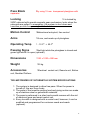
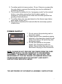
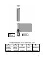
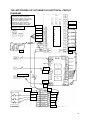
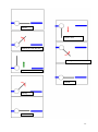
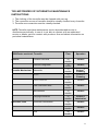
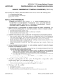
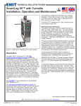
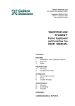
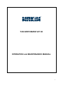
T230 MOTORIZED VIP 3K
OPERATION and MAINTENANCE MANUAL
1
TABLE OF CONTENTS
BEFORE YOU START
3
TURNSTILE SAFETY INSTRUCTIONS
3
TURNSTILE USER INSTRUCTIONS
3
T230 MOTORIZED VIP 3KTURNSTILE TECHNICAL SPECIFICATIONS
4
T230 MOTORIZED VIP 3KTURNSTILE SYSTEM SPECIFICATIONS
5
POWER SUPPLY
5
T230 MOTORIZED VIP 3KTURNSTILE ASSEMBLY INSTRUCTIONS -1
6
T230 MOTORIZED VIP 3KTURNSTILE MATERIAL LIST
7
T230 MOTORIZED VIP 3KTURNSTILE ELECTRICAL CIRCUIT DIAGRAM 8
T230 MOTORIZED VIP 3KTURNSTILE -HOW TO RUN
9
2
T230 MOTORIZED VIP 3KTURNSTILE MAINTENANCE INSTRUCTIONS
11
T230 3K TURNSTILE TROUBLESHOOTING
12 11
3
BEFORE YOU START
Thank you for purchasing T230 Motorized Vip 3K Turnstile. Please, carefully
read the instructions contained in this manual for a long and smooth operation
of the turnstile and keep the manual for future references.
TURNSTILE SAFETY INSTRUCTIONS
• It is recommended to read all safety and maintenance instructions before
installing and using the turnstile.
• Read the manual, before operating the turnstile.
• Do not open the turnstile, due to safety precautions. Any repairment must be
done
only by authorized services. Modifications made by user may result in danger
for the
turnstile and people.
• Do not operate damaged turnstiles and call an authorized service
immediately.
• Comply with the power and voltage values specified in the technical
specifications of
turnstile.
• Comply with the operating temperature range specified in the technical
specifications of turnstile.
• Check the power supply and control the card connections before reenergizing the turnstile afterwards any maintenance or damage.
• Use certificated spare parts and accessories approved and allowed by the
producer.
• In any problem, cut off the electrical connections of the turnstile and call an
authorized service.
• During the cleaning and maintenance, cut off the electrical connections.
Otherwise damage to the parts may result.
• Use wet rag for cleaning.
• Keep the turnstile away from over heated or fire environment. Over heat
may result
in a damage to the turnstile.
• Do not use the turnstile in high magnetic areas.
• Do not expose the turnstile to excessive water in order to prevent any
penetration.
• Provide your turnstile with electrical grounding connection.
4
TURNSTILE USER INSTRUCTIONS
• The turnstile is designed so as to allow one person to pass each time and
more than one person mustn’t try to pass at the same time.
• In case of not functioning properly, avoid actions that may result in damage
to the turnstile.
• In case of any malfunctioning, in order to avoid further damage to the
system, should the system be taken in idle state or mustn’t be used.
• Substances harmful to turnstile mustn’t be used for
cleaning.
The manufacturer will not accept any responsibility for any inquiry or damage
resulting from incompliance with the security and safety instructions indicated
above.
T230 MOTORIZED VIP 3KTURNSTILE TECHNICAL SPECIFICATIONS
Power
: 220V 50Hz / 30 W
Operating Voltage :24 V DC +- %20
Body Features
:Waterproof body with 1,5 mm 304 grade
stainless steel
Control System
:It is commanded by Dry Contact or any other
recommended voltage. It is possible to use with all kinds of access
control units or token mechanisms. Additionally, it can be commanded by
RS232 and RS485 (optional).
5
Pass Block
:By using 15 mm
transparent plexiglass with
separator.
Locking
:It is locked by
24DC solenoid with special magnetic gear mechanism, locks when the
solenoids are pulled. In emergency, the system is shut down and
turnstiles provide free passing in both directions.
Motion Control
:Bidirectional entry/exit, free control
Arms
:14 mm, and made up of plexiglass.
Operating Temp
: - 10 C0 - + 50 C0
Passing Signs
:Red light while the plexiglass is closed and
green light while it is open (optional).
Dimensions
:230 x 1030 x 990 mm
Weight
:35 kg
Accessories
:Electrical
control unit, Remote unit, Button
unit, Modular Platform
T230 MOTORIZED VIP 3KTURNSTILE SYSTEM SPECIFICATIONS
1. The system is designed to allow free pass. When the power is
turned off, the arm turns freely.
2. The parts of the turnstile carrying load and giving motion are made
up of stainless steel or galvanized materials.
3. The pass is performed in a silent and smooth manner with the aid
of electronic gear and smart control unit.
4. Every turnstile is designed with a control card, however, it can be
modified and programmed for customer needs and wants
(optional).
6
5. Turnstiles switch to home mode in 15 sec if there is no pass after
the entry data is received (the locking time can be calibrated if
needed as optional).
6. The turnstile is switched to the “emergency mode” by the manual
button or any data coming from the fire alarm system. In
emergency, the system is shut down and turnstiles provide free
passing in both directions.
7. Turnstiles allow only one pass based on the Access type (token,
card reader, button, etc.).
8. Entry data is transferred to terminal after the necessary system
infrastructure.
POWER SUPPLY
1. Do not remove the protecting seal on
the power supply.
2. Please perform your operations paying
attention to the warnings, electricity and
safety fuse data on the protecting seal
and power supply.
3. On the label placed on the power
supply, the connection points are
shown. Please follow the signs on the
label while carrying out the connection.
NOTE: PLEASE DO NOT PROVIDE THE POWER FROM THE CARD
OR POWER SUPPLY ON THE TURNSTILE TO THE EXTERNAL
EQUIPMENT. THE MANUFACTURER WILL NOT ACCEPT ANY
RESPONSIBILITY FOR ANY INQUIRY OR DAMAGE RESULTING
FROM INCOMPLIANCE WITH THE SECURITY AND SAFETY
INSTRUCTIONS INDICATED ABOVE.
T230 MOTORIZED VIP 3KTURNSTILE ASSEMBLY INSTRUCTIONS
7
1. Select a proper location so as not to obstruct turnstile’s operation.
2. Check the structure of the ground of installation site to ensure the
necessary stability requirements.
3. Mark the hole places on the ground in which the turnstile will be
mounted.
4. Drill the marked mounting holes by Ø10 drill bit and clean the dust
inside the hole by the help of the air.
5. Fix the steel anchors to the drilled holes. If the ground is not strong,
fix the steel anchors after using chemical soil mixture. (Wait 20
minutes for hardening of chemical soil mixture)
6. Pass the power and data cables which are prepared before through
the hole on mounting plate.
7. Put the mounting plate on the steel anchors and after putting the
washer and nuts, fix the ground.
8. You can see the pictures and drawing illustrating anchor and
turnstile’s mounting operation.
8
HOLE
FOR
CABLES
ANCHOR
T230 MOTORIZED VIP 3K MATERIAL LIST
A
B
C
D
E
M6x10
M8x25
M8
M8
M8
STEEL
INBUS RONDELA
NUT
WASHER
ANCHOR
BOLT
4 pieces 4 pieces
4 pieces 4 pieces 4 pieces
9
T230 MOTORIZED VIP 3KTURNSTILE ELECTRICAL CIRCUIT
DIAGRAM
If you want it not to open anti
clockwise, the wire connected to
GEMO AUX SUPPLY OUT +18 V is
connected to GEMO 12 (INHIBIT CW)
entry. If you want it not to open
clockwise, the wire connected to
GEMO AUX SUPPLY OUT +18 V is
connected to GEMO 121 (INHIBIT
CCW) entry.
Microswitch layout
red-led
brown
green-led
pink
D
I
S
P
L
A
Y
grey
white
green
yellow
black
red
red
blue
brown
Power supply
black
red
brown
red
yellow
yellow
green
green
white
white
grey
pink
brown
10
T230 MOTORIZED VIP 3KTURNSTILE -HOW TO RUN
[A] THE CONTROL IS STARTED IN 3 SEC AFTER POWER CUT.
IF THE ARM IS IN ZERO MODE (CLOSED MODE), IT IS LOCKED AT THIS
POSITION.
IF THE ARM IS BETWEEN OPEN & CLOSED POSITION, IT MOVES IN CCW
DIRECTION.
IF THE ARM COMES TO THE CLOSED MODE, IT STOPS & LOCKS.
IF THE ARM IS OPEN IN CCW DIRECTION, IT STOPS AND CLOSES AFTER 5
SEC.
NOTE: IF IT IS INHIBITED IN CCW DIRECTION IN SETUP, ZERO MODE
DIRECTION IS CW.
[B] THE BUTTONS ON THE REMOTE CONTROL;
1) CCW (COUNTER CLOCKWISE) BUTTON: IT IS FOR MOVING THE ARM IN
ANTI CLOCKWISE DIRECTION. IF THE ARM IS CLOSED, IT OPENS IN CCW
DIRECTION. IF CW IS OPEN, THE ARM IS CLOSED.
2) CW (CLOCKWISE) BUTTON: IT IS FOR MOVING THE ARM IN CLOCKWISE
DIRECTION. IF THE ARM IS CLOSED, IT OPENS IN CW DIRECTION. IF CCW IS
OPEN, THE ARM IS CLOSED.
NOTE: IF THE BUTTON IS PRESSED DURING OR AFTER THE ARM IS OPENED,
THE ARM REMAINS OPEN. IN ORDER TO CLOSE THE ARM, PRESS THE
OTHER BUTTON. IF THE ARM IS OPEN AND NOT IN IDLE MODE, IT IS CLOSED
AFTER 5 SEC (TIME CAN BE CALIBRATED IN SETUP).
3) IDLE/CONTROLLED BUTTON: WHEN PRESSED, THE ARM IS IDLE AND IT
CAN BE MOVED BY HAND. WHEN THE BUTTON IS IN NORMAL POSITION, THE
EQUIPMENT IS CONTROLLABLE.
[C] USING SENSOR WHILE OPENING;
IF THE SENSOR DETECTS A PERSON, THE ARM IS OPENED AFTER
PRESSING THE “OPEN ARM” BUTTON.
[D] RED: READY / GREEN: ON WARNING LIGHT;
AS OPENING GREEN BLINKS, WHEN OPENED GREEN IS ON.
AS THE ARM IS CLOSING RED BLINKS, WHEN CLOSED RED IS ON.
11
Closed
Open in CW
Opening in CCW direction
Closing in CCW direction
Open in CCW direction
Closed
Closing
Closed
12
T230 MOTORIZED VIP 3KTURNSTILE MAINTENANCE
INSTRUCTIONS
1. The clothing of the turnstile must be cleaned with wet rag.
2. The connection screws of turnstile should be visually checked every 6 months.
3. Turnstile arm connection must be visually checked.
NOTE: Turnstile must have maintenance service by authorized service or
distributors periodically. In case it is not able to contact with an authorized
service or dealer, get into contact with producer firm and obtain information on
periodical maintenance.
T250 Electro mechanic Turnstile
General
Turnstile Plexi Bolts
Time
Operation
12
Control
months
Ground Fixing Bolts
12
Control
months
Turnstile Mechanism
Solenoids
12
months
Wheel
Carrier Shaft Nut
12
Control +
Cleaning
months
Control +
Cleaning
12
Control
months
Gear Connection Bolts
12
Control
months
Microswitches
12
Control
months
Carrying mechanism
Electronic Card
Electrical Connections
12
months
Control +
Lubrication
12
Control
months
Motor Connection Cables
12
Control
months
PLC
12
Control
months
13
T230 TURNSTILE TROUBLESHOOTING
Fault
Reason(s)
Solution(s)
Although the electricity is on, the
arms cannot be locked, the
displays are turned off, and the
turnstile is functionless.
1.Power supply may be off or
broken.
1.Check whether the
After one pass, the turnstile is not
locked and it allows multiple
passes.
Although the electricity is on the
arms are turning freely.
The turnstile does not send info
after pass.
2.Electrical fuse could be
blown out.
1.Direction sensor
microswitches could be broken.
2.Electronic card could be
broken.
3.Magnetic gear could be
broken.
1. Solenoid could be broken or
there may be connection
defects.
2. Electronic card could be
broken.
1. Cycle sensor micro switches
could be broken or there may
be connection defects.
2. There may be defects in the
cable transferring data.
3. Electronic card could be
broken.
Turnstile arms are giving noise due The main mechanism may have
to friction while turning.
been hit and/or the nut could
be loosened up.
The entry and exit speeds are
The turnstile may not be
different.
mounted in a level ground.
The turnstile is not standing at 90
degrees, and it is exceeding the
level.
Switch positions may be tilted
due to hit or switches could be
broken due to hits.
electrical cable is
plugged in.
2.Change power
supply if needed.
1.Replace
microswitches.
2. Replace electronic
card.
3. Check the magnetic
gear connections and
replace if broken.
1. Replace
solenoid and also
check the
connections.
2. Replace
electronic card.
1. Replace
microswitches and
check the connections.
2. Check the cables
carrying data.
3. Replace electronic
card.
Tighten the nut. If that
is not the case, replace
the entire mechanism.
The turnstile should be
mounted on a level
ground and this
operation should be
checked by water
balance.
1. Calibrate the switch
positions.
2. Replace the
switches.
14
Notes:
15