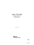
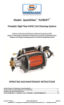
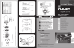
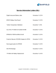
1
LVC250LP
250 GALLON LOW PROFILE LAV CART
PRODUCT MANUAL
Par-Kan Company
2915 West 900 South
Silver Lake, IN 46982
Phone: 1-800-291-548
Phone: 260-352-2141
Fax: 260-352-0701
Contact: GSE Sales Department
Email: [email protected]
Website: www.par-kan.com
*** Important ***
Read User’s Manual Completely Prior to Operating, Towing, or Servicing Cart
LVC250LP
CUSTOMER: __________________________________
SERIAL # _____________________________________
MANUFACTURING DATE: -_____________________
2
LVC250LP Manual Table of Contents
Page 1........................................ Cover Page
Page 2........................................ Unit Information
Page 3........................................ Table of Contents
Page 4........................................ Manual Introduction
Page 5........................................ Warranty Information
Page 6........................................ General Information
Page 7........................................ Operating Instructions
Page 8........................................ Safety Precautions
Page 9........................................ Specifications and Capabilities
Page 10...................................... Maintenance / Overhaul
Page 11...................................... Troubleshooting
Page 12...................................... Illustrated Parts Listing
Page 13 ..................................... Electrical Diagrams
Page 14-15 ................................ Plumbing Diagrams
Page 16-17 ................................ Decal Package
Page 18-19 ................................ 5th Wheel Assembly
Page 20...................................... Brake Bar Assembly
Page 21...................................... Spindle & Hub Assembly
Page 22...................................... Replacement Parts
User’s Manuals
-Fill Rite Flow Meter User’s Manual
-Westward 12V Battery Charger User’s Manual
-Dakota Space Heater User’s Manual
3
LVC250LP Manual Introduction
This manual incorporates information for Par-Kan Company’s Ground Support Equipment Division
Lavatory Cart, model LVC250LP and includes general information, operation, maintenance, overhaul
and illustrated parts lists. This manual replaces all Par-Kan Company’s LVC250LP manuals previously
issued in their entirety.
This manual is a compilation of the best information available at the time of writing. If errors or misinformation are found, change requests should be submitted in writing to the manufacturer.
If you have any questions about this product or would like further information about Par-Kan Company’s
ground support equipment please contact the manufacturer at:
Par-Kan Company
Ground Support Equipment Division
P.O. Box 219
2915 West 900 South
Silver Lake, IN 46982
(260) 352-2141
(260) 352-0701 Fax
4
Par-Kan Company – Ground Support Equipment
Model LVC250LP Warranty
Par-Kan Company’s Ground Support Equipment is warranted to the original purchaser
to be free from defects in material and workmanship for a period of two years from the date of
purchase as dated on Par-Kan’s original invoice.
Par-Kan will replace during the warranty period, subject to an examination by an
authorized representative of Par-Kan, any warranted part which proves defective in
material and/or workmanship under normal installation, use, and service. Parts must be
returned, and transportation charges prepaid to our factory. Any changes to Par-Kan equipment as a result of modifications, misuse, abuse, neglect, accident, vandalism, fire, flood,
other acts of God, or improper installation will void this warranty.
If Par-Kan receives notice of such defects during the warranty period, Par-Kan will either, at its option, repair or replace products which prove to be defective. Other
manufacturer’s warranties may apply for parts purchased by Par-Kan. Par-Kan Company
makes no other warranty, either expressed or implied, with respect to this product. Any
special, incidental, or consequential damages arising from any breach of warranty are
specifically excluded hereunder.
5
LVC250LP General Information
Steering:
Ball Bearing Turntable Steering
Wheels:
5 Bolt hub assembly with bearings (1,750 lb. load capacity each)
Removable Spindles: 1-3/4” diameter
Tires: 6.00 X 6.90 X 9.0 Pneumatic Carlisle Tire
Parking Brakes:
Tow bar activated friction brake
Tow Bar:
2-1/2” I.D. Swivel tow bar lunette ring
5 Ton capacity
Finish:
Painted Epoxy
Reflectors:
3” Diameter (Amber / Red) D.O.T. approved
Location: Front, Rear, and Sides
Cart Design:
Bed: 14ga carbon steel
Shell: 14ga carbon steel
Tank Design:
14ga stainless steel
Pump:
FloJet self priming electric pump
Options:
12 foot dump hose
Winterization Package
6
LVC250LP Operating Instructions
1. Check to ensure the unit is unplugged from power source, all hoses are secured, and that all access
doors and hatches are closed.
2. Release the parking break by pushing the tow bar back towards the unit and lifting up the brake
latch with foot, the brakes will release as the tow bar is lowered into a horizontal position. Do not
drop the tow bar.
3. Lay tow bar in a horizontal position and pin the tow bar to the towing vehicle. The tongue should
be securely attached to the vehicle using all safety devices to ensure that the unit does not disconnect
from the tow vehicle
4. Tow the unit to the desired location, (CAUTION: DO NOT EXCEED 15MPH), turn the tow vehicle engine off and set the parking brake.
5. Remove the dump hose from storage bracket and connect to aircraft. Remove the filler hose from
the rear storage compartment. To remove cap from filler coupler grasp cap in left hand and grasp coupler in right hand, turn coupler counter-clockwise while turning cap clockwise, cap will release.
(CAUTION: POINT COUPLER AWAY FROM BODY WHEN REMOVING CAP, THE
HOSE MAY BE UNDER PRESSURE) Connect the filler hose to the aircraft and open the
ball valve on filler hose. At the rear of the unit open the meter access door and reset the meter
turn the power switch to on and dispense the desired amount of fluid. When transfer is complete
turn off power switch, and close access door. Close the ball valve on filler hose and remove from
aircraft, replace cap on filler coupler, stow filler hose in rear compartment. Disconnect dump
hose from aircraft and stow on storage bracket. Ensure that all caps are securely installed on
aircraft and that the access panel or panels have been secured. Check to ensure that all hoses have
been disconnected and properly stored, pump is turned off, and that all access doors on unit are closed
prior to moving unit. To empty the dump tank position dump pipe (located at left rear of vehicle) over
dumping facility, open dump valve and empty contents, close valve after dumping is complete.
6. Tow the unit to designated parking area, and disconnect the tow bar from the tow vehicle. To activate the parking brake push tow bar towards unit until the brake latches. When tow bar is in the vertical position the parking brake is set. Plug the unit back into power source and check indicator lamp on
right rear of unit to ensure power is being received.
7
LVC250LP Safety Precautions
TOWING:
The LVC250LP cart is designed for aircraft ramp use only; it is not intended for highway or off-road
use. Towing speed should not exceed 15mph. When traveling over rough surfaces or during turning,
speeds should be reduced. Always stow hoses and close all access doors prior to moving unit. CAUTION: NEVER ATTEMPT TO MOVE THE UNIT WHILE HOSES ARE CONNECTED TO
THE AIRCRAFT.
PARKING:
When the unit is parked the tow bar should be latched in the upright, vertical, position to engage the
parking brake. If unit is not connected to the tow vehicle the parking brake must be set to prevent the
unit from rolling.
OPERATING:
Before moving unit, ensure that the power supply has been disconnected from the outlet. When
moving the unit by hand, use caution, especially in wet conditions. When removing cap from filler
coupler point coupler away from body, the hose may be under pressure. It is recommended that when
servicing lavatory system that proper protective gear be worn at all times.
8
LVC250LP Specifications and Capabilities
Dimensions:
Length :162”
Width: 64”
Height: 30”
Empty Weight: (Approx.)
1920 lbs.
Tank Capacity:
- Fill Tank
- Waste Tank
378.5 Liters (100 gal.)
567.8 Liters (150 gal.)
Pump Flow Rate:
FloJet
4.5 g.p.m.
Speed Limit: Towing speed should not exceed 15 mph.
9
LVC250LP Maintenance / Overhaul
Servicing:
Proper maintenance is an essential part of a long life for the LVC250LP. As with any equipment the cart needs inspections, lubrications and adjustments to keep it in good condition while providing maximum protection for the equipment.
WARNING: Before removing or installing any components, be sure the trailer is on level ground with the wheels securely blocked.
Wheels and Tires:
Check the tire pressure weekly. The proper pressure is labeled on the tire.
Check and adjust the wheel bearings during the first few days of operation.
To tighten wheel bearings:
1. Remove dust cap
2. Remove cotter pin from the castle nut and tighten the nut until there is a slight drag on the bearing while turning the wheel.
3. Loosen the nut one slot and reinsert the cotter pin.
4. Following this adjustment there should be a slight amount of drag on the bearing.
5. Replace the dust cap.
Wheel Bearing Lubrication:
Pack the wheel bearings every 6 months or as needed with S.A.E. multi-purpose grease.
Brake Adjustment:
Periodic adjustment of the brake is needed to assure proper operation.
1. Raise the tongue so that the tongue latch touches the tongue.
2. With the tongue in this position, check the rub brake, the rub brake should just touch the tires.
3. If the rub brake is not properly adjusted, adjust the draglink so that the rub brake touches the tire. To adjust the
draglink loosen the locknuts and adjust the threaded rod accordingly, then retighten the lock nuts against the
brake yoke.
Battery:
Check the battery water level monthly, the water level should be near the top, refill with distilled water.
FIFTH WHEEL STEERING
Check the steering assembly daily; ensure that the tow bar pin assembly and cotter pin are securely fastened to the lower
fifth wheel box. WARNING: FAILURE TO ENSURE THAT PIN IS SECURED COULD LEAD
TO LOSS OF STEERING AND CONTROL OF THE UNIT.
Storage:
When storing the unit for extended period of time, the following procedures are suggested
Touch up all worn or damaged paint
Lift and block unit with tires lifted off the ground.
Remove battery
Drain and rinse tanks
Drain meter and hoses
10
LVC250LP Troubleshooting
If the brakes do not engage or disengage?
Check the brake yoke bar adjustment
If the steering on the unit will not turn?
Check to ensure the brake is not engaged
If the unit pulls to one side?
Check the tire pressure and bearings
If the tow bar will not stay in the locked position
Check the tow bar latch and latch bar for excessive wear
Check the brake yoke bar for any adjustment
If the unit will not pump fluid?
Check the fluid level in tank then check to ensure that all valves are open
Check the fill hose for kinks or blockages
If meter does not work properly?
- Check to ensure fluid is being pumped, if fluid is flowing stop pumping and reset meter
11
LVC250LP Illustrated Parts Listing
The illustrated parts list contains a breakdown of the LVC250LP. All parts
contained in the lavatory cart that can be disassembled, repaired, manufactured,
replaced or reassembled are listed.
Each sketched assembly is followed immediately by its detailed parts list.
Item Number Column: The figure and index numbers key the detailed parts list to the applicable illustration.
Part Number Column: This column contains the manufacturer’s and vendor’s part numbers.
All parts listed on the following pages are available through Par-Kan Company.
12
LVC250LP Electrical Diagram
7
10
8
9
6
5
11
4
3
12
2
1
Key #
1
Part Number
640084
Description
Indicator Light, Red LED dot
2
640057
Switch, Weatherproof Momentary On/Off/On
3
660010
Light, License Plate
4
630505
Receptacle, Plastic Box 1/2 FSE 2 Recp.
5
640030
Indicator Light
6
630504
Receptacle, GFCI White 120 20A FD
7
640204
Water Heater, W/Thermo-120V-1500W
8
640226
Battery, 12 Volt Deep-Cell GR 24 GSE
9
640022
Switch, Toggle
10
220561
Pump, Water 12V. W/Press. SW.(Flojet)
11
640252
Battery Charger, Automatic 12 Volt / 10 Amp.
12
640222
Heater, Electric Space 12 Volt DC
13
LVC250LP Plumbing Diagram Blue Water Tank
Key #
Part Number
Description
#1
220657
Coupling, Lav. Water Serv.!” Ext Collar
#2
220353
Hose Clamp, 3/4” SS **6812**
#3
220302
Hose, 1” ID Reinforced PVC Clear 6”
#4
224024
Adapter, 3/4” NPT X 1” Barb-Poly
#5
220203
Valve, 3/4” Ball/Brass
#6
224021
Adaptor, 3/4” NPT X 3/4” Barb Nylon
#7
220301
Hose 3/4” ID Reinforced PVC (Clear) 144”
#8
220612
Meter, Nickel Plt. Ports, LAV / PWC Meter
#9
225035
Elbow, 1” NPT X 3/4” Bango 90 degree
#10
220301
Hose 3/4” ID Reinforced PVC (Clear) 18”
#11
220561
Pump, Water 12 V. W/Press. SW. (Flowjet)
#12
220301
Hose 3/4” ID Reinforced PVC (Clear) 8”
#13
L250LP-8W000
100 Gallon Blue Water Tank
14
LVC250LP Plumbing Diagram Open Dump System
5
4
3
2
1
Key #
Part Number
Description
#1
222100
4” Nipple x 5” long
#2
220227
Bango Ball Valve
#3
223159
Adaptor, 4” Male to Female
#4
L280LP-8P600
4” PVC Schedule 40
#5
223285
4” Elbow
15
LVC250LP Decal Package
16
LVC250LP Decal Parts Listing
Key #
Part Number
Description
1
250037
Decal, Meter / Battery / Charger Compartment
2
250042
Decal, Fill Hose Compartment
3
250044
Decal, Open Before / Close After Use
4
250038
Decal, Install Fill Cap After Use
5
250041
Decal, Lavatory Service
6
250040
Decal, Charger / Heater
7
250069
Decal, Par-Kan Company
8
250052
Decal, Flush Water Fill Port
9
250021
Decal, Refill Level
10
250250
Decal, Made in the U.S.A
11
250026
Decal, Set Brake
12
250022
Decal, Do Not Run Pump Dry
13
250029
Reflector, 3” Round Red
14
250030
Reflector, 3” Round Amber
15
250024
Decal, Max To Speed 15 mph
16
250063
Decal, Caution – Operators Manual
17
250035
Decal, No Standing On Tank
17
LVC250LP 5th Wheel Assembly
1
2
3
4
5
7
6
8
15
14
13
11
9
10
12
18
LVC250LP 5th Wheel Parts Listing
Key #
Part Number
Description
1
210361
5th Whl Bolt (1-1/4”-12X5 W/HCS) (Replaced)
2
L250LP-2W035
Upper 5th Wheel Weldment
3
241197
Turntable, Laminated W/ 3/4” Chrome Balls
4
CBC5010-2P501
Latch, Towbar
5
L250LP-2W016
Lower 5th Wheel Weldment
6
216507
Locknut, 3/8”-16 HEX 2-Way-Zinc
7
241000
Spindle
8
241025
Hub Assy. 5 Bolt 4-1/2” “Standard” GSE
9
217003
Washer, 3/8” USS Flat Zinc
10
211069
HHCS, 3/8”-16 X 3-1/2” GR5 Zinc
11
CBC510-2W041
Tow Bar Pin Weldment
12
210104
Roll Pin, 3/8” X 2 1/2” (Spring Pin)
13
216220
Nut, 1-1/4”-12 Slotted Hex Plain
14
270510
Tow Bar, Assy. Swivel TB-20PKS
15
210115
Roll Pin, 1/8” X 3/4”
16
L250LP-2S018
Lower 5th Wheel Assembly
19
LVC250LP Brake Bar Assembly
1
2
3
4
5
6
Key #
Part Number
Description
1
2
211117
L250LP-1W000
HHCS, 1/2”-13 X 2” GR5 Zinc
Brake Bar
3
211124
HHCS, 1/2”-13 X 4” GR5 Zinc
4
216511
Locknut, 1/2”-13 HEX 2-Way-Zinc
5
L250LP-1W001
Brake Adjustment Bar
6
211127
HHCS, 1/2”-13 X 5” GR5 Zinc
20
LVC250LP Spindle & Hub Assembly
1
2
Key #
3
4
5
6
7
8
Part Number
9
10
11
12
Description
1
241108
Cotter Pin
2
241107
Spindle Nut
3
241109
Dust Cap
4
241106
Washer with D shaped hole
5
241105
Outer Bearing
6
241104
Outer Cup
7
241103
Lug Bolt
8
241025
Hub Assembly ( Includes part numbers 1-11 )
9
241102
Inner Cup
10
241101
Inner Bearing
11
241100
Grease Seal
12
241000
Spindle
**
241110
Lug Nut
** Not included in the illustration
21
LVC250LP Replacement Parts
1
2
4
5
7
3
6
8
Key #
Part Number
Description
#1
640222
Heater, Electric Space 12 Volt DC
#2
220561
Pump, Water 12V. W/Press. SW. (Flojet)
#3
640204
Water Heater, W/Thermo-120V-1500W
#4
220612
Meter, Nickel Plt. Ports, LAV / PWC Meter
#5
L250LP-4A001
Outer Shell Cover
#6
640030
Indicator Light
#7
241058
6.00 x 6.90 x 9.0 Carlisle Tire
#8
L250LP-8W001
150 Gallon Waste Tank
#9
L250LP-8W000
100 Gallon Blue Water Tank
#10
220680
Hose, 4” x 12” LAV Blue/Clear Crush Proof
9
10
22