1
Elite Series
User Manual
EL-2800M-PMCL
EL-2800C-PMCL
2.8M Digital Progressive Scan
Monochrome and Color Camera
Document Version: 1.5
EL-2800-PMCL_Ver.1.5_Oct2013
1043E-1302
EL-2800M-PMCL / EL-2800C-PMCL
Notice
The material contained in this manual consists of information that is proprietary to JAI Ltd., Japan
and may only be used by the purchasers of the product. JAI Ltd., Japan makes no warranty for the
use of its product and assumes no responsibility for any errors which may appear or for damages
resulting from the use of the information contained herein. JAI Ltd., Japan reserves the right to
make changes without notice.
Company and product names mentioned in this manual are trademarks or registered trademarks of
their respective owners.
Warranty
For information about the warranty, please contact your factory representative.
Certifications
CE compliance
As defined by the Directive 2004/108/EC of the European Parliament and of the Council, EMC
(Electromagnetic compatibility), JAI Ltd., Japan declares that EL-2800M-PMCL and EL-2800C-PMCL
comply with the following provisions applying to its standards.
EN 61000-6-3 (Generic emission standard part 1)
EN 61000-6-2 (Generic immunity standard part 1)
FCC
This equipment has been tested and found to comply with the limits for a Class B digital device,
pursuant to Part 15 of the FCC Rules. These limits are designed to provide reasonable protection
against harmful interference in a residential installation. This equipment generates, uses and can
radiate radio frequency energy and, if not installed and used in accordance with the instructions,
may cause harmful interference to radio communications. However, there is no guarantee that
interference will not occur in a particular installation. If this equipment does cause harmful
interference to radio or television reception, which can be determined by turning the equipment
off and on, the user is encouraged to try to correct the interference by one or more of the following
measures:
1. Reorient or relocate the receiving antenna.
2. Increase the separation between the equipment and receiver.
3. Connect the equipment into an outlet on a circuit different from that to which the receiver is
connected.
4. Consult the dealer or an experienced radio/TV technician for help.
Warning
Changes or modifications to this unit not expressly approved by the party
responsible for FCC compliance could void the user’s authority to operate the
equipment.
- 2 -
EL-2800M-PMCL
Supplement
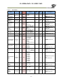
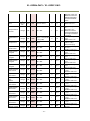
The following statement is related to the regulation on “ Measures for the Administration
of the control of Pollution by Electronic Information Products “ , known as “ China RoHS “.
The table shows contained Hazardous Substances in this camera.
mark shows that the environment-friendly use period of contained Hazardous
Substances is 15 years.
嶷勣廣吭並㍻
嗤蕎嗤墾麗嵎賜圷殆兆各式根楚燕
功象嶄鯖繁酎慌才忽佚連恢匍何〆窮徨佚連恢瞳麟半陣崙砿尖一隈〇云恢瞳ゞ 嗤蕎嗤
墾麗嵎賜圷殆兆各式根楚燕 〃泌和
桟隠聞喘豚㍉
窮徨佚連恢瞳嶄根嗤議嗤蕎嗤墾麗嵎賜圷殆壓屎械聞喘議訳周和音氏窟伏翌
亶賜融延、窮徨佚連恢瞳喘薩聞喘乎窮徨佚連恢瞳音氏斤桟廠夛撹冢嶷麟半
賜斤児繁附、夏恢夛撹冢嶷鱒墾議豚㍉。
方忖仝15々葎豚㍉15定。
EL-2800C-PMCL
Supplement
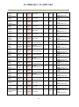
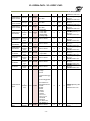
The following statement is related to the regulation on “ Measures for the Administration
of the control of Pollution by Electronic Information Products “ , known as “ China RoHS “.
The table shows contained Hazardous Substances in this camera.
mark shows that the environment-friendly use period of contained Hazardous
Substances is 15 years.
嶷勣廣吭並㍻
嗤蕎嗤墾麗嵎賜圷殆兆各式根楚燕
功象嶄鯖繁酎慌才忽佚連恢匍何〆窮徨佚連恢瞳麟半陣崙砿尖一隈〇云恢瞳ゞ 嗤蕎嗤
墾麗嵎賜圷殆兆各式根楚燕 〃泌和
桟隠聞喘豚㍉
窮徨佚連恢瞳嶄根嗤議嗤蕎嗤墾麗嵎賜圷殆壓屎械聞喘議訳周和音氏窟伏翌
亶賜融延、窮徨佚連恢瞳喘薩聞喘乎窮徨佚連恢瞳音氏斤桟廠夛撹冢嶷麟半
賜斤児繁附、夏恢夛撹冢嶷鱒墾議豚㍉。
方忖仝15々葎豚㍉15定。
EL-2800M-PMCL / EL-2800C-PMCL
- Contents Before using this manual ....................................................................1. General ....................................................................................2.
Camera composition ...................................................................3.
Main features ............................................................................4.
Locations and functions ...............................................................4.1
4.2.
6
7
7
8
9
-
Locations and functions .................................................................... - 9 Rear Panel .................................................................................. - 10 -
5. Input and output ......................................................................... - 11 5.1
Connectors and pin assignment ......................................................... - 11 -
5.1.1
12-Pin connector...................................................................................... - 11 -
5.1.1.1
5.1.1.2
5.1.2
Camera Link connector .............................................................................. - 11 -
5.1.2.1
5.1.2.2
5.1.3
5.1.4
5.1.5
5.2
5.3
Figure ........................................................................................................ - 11 Pin assignment ............................................................................................. - 12 -
AUX Standard Hirose 10-Pin Connector ........................................................ - 12 AUX Type 2 Hirose 10-Pin Connector (Factory option) ....................................... - 13 AUX Type 3 Hirose 10-Pin Connector (Factory option) ...................................... - 13 -
Camera Link interface ..................................................................... - 14 Digital IN/OUIT interface .................................................................. - 15 -
5.3.1
5.3.2
5.3.3
5.3.4
5.3.5
5.3.6
5.3.7
5.4
Line Selector .......................................................................................... - 15
Line source ............................................................................................ - 15
Line Mode .............................................................................................. - 15
Line Inverter ........................................................................................... - 15
Line Status ............................................................................................. - 16
Line Format ............................................................................................ - 16
GPIO ..................................................................................................... - 16
-
Pulse Generator ............................................................................ - 17 -
5.4.1
5.4.2
5.4.3
5.4.4
5.4.5
5.4.6
5.4.7
5.4.8
5.4.9
5.4.10
5.4.11
6.
Figure ........................................................................................................ - 11 Pin assignment ............................................................................................. - 11 -
Clock Pre-scaler....................................................................................... - 18
Pulse Generator Selector ............................................................................ - 18
Pulse Generator Length ............................................................................. - 19
Pulse Generator Start Point ........................................................................ - 19
Pulse Generator End Point .......................................................................... - 19
Pulse Generator Repeat Count ..................................................................... - 19
Pulse Generator Clear Activation .................................................................. - 19
Pulse Generator Clear Sync Mode ................................................................. - 19
Pulse Generator Clear Source ...................................................................... - 21
Pulse Generator Inverter .......................................................................... - 22
Pulse Generator Setting table .................................................................... - 22
-
Sensor layout, output format and timing ........................................ - 23 -
6.1
Sensor layout ................................................................................ - 23 -
6.1.1
6.1.2
6.2.
Camera output format .................................................................... - 24 -
6.2.1
6.2.2
6.2.3
6.2.4
6.3
Monochrome sensor .................................................................................. - 23 Bayer color sensor ................................................................................... - 23 1X-1Y.................................................................................................... - 24
1X–2YE .................................................................................................. - 24
1X2–1YE ................................................................................................. - 25
1X2–2YE ................................................................................................. - 25
-
Output timing ........................................................................ - 26 -
6.3.1
Horizontal timing ..................................................................................... - 26 -
6.3.1.1
6.3.1.2
Output format
Output format
1X2-2YE , 1X2–1Y ...................................................................... - 26 1X–2YE , 1X–1Y......................................................................... - 26 -
- 3 -
EL-2800M-PMCL / EL-2800C-PMCL
6.3.2
Vertical timing ........................................................................................ - 27 -
6.3.2.1
6.3.2.2
6.3.3
6.4
7.
Output format
Output format
1X2–2YE , 1X–2YE ...................................................................... - 27 1X2–1Y , 1X–1Y ......................................................................... - 28 -
ROI (Region Of Interest) ............................................................................ - 28 -
Digital output bit allocation.............................................................. - 29 -
Operating modes ...................................................................... - 29 -
7.1.
Acquisition control (change the frame rate) ........................................ - 29 -
7.1.1
7.1.2
7.2.
Acquisition frame rate .............................................................................. - 29 Calculation of default frame rate ................................................................. - 30 -
Exposure control .......................................................................... - 30 -
7.2.1
7.2.2
7.2.3
7.3.
Exposure Mode ........................................................................................ - 30 Exposure Time ........................................................................................ - 31 Exposure Auto ........................................................................................ - 31 -
Trigger Mode ............................................................................... - 32 -
7.3.1
7.3.2
7.3.3
7.3.4
7.4.
7.5.
Trigger Source ........................................................................................
Trigger Activation ....................................................................................
Trigger Overlap .......................................................................................
Trigger Delay ..........................................................................................
If the overlap setting is lse i ....................................................................... - 33 If the overlap setting is lse is 54 .................................................................. - 34 -
Trigger Width mode ...................................................................... - 34 -
7.6.1
7.6.2
7.7.
7.8.
7.9.
If the overlap setting is lse ( ....................................................................... - 35 If the overlap setting is lse (1X24 ................................................................. - 36 -
RCT mode................................................................................... - 36 PIV (Particle Image Velocimetry) ...................................................... - 37 Sequential Trigger ........................................................................ - 38 -
7.9.1
7.9.2
7.10.
8.
-
Normal continuous operation (Timed Exposure Mode/Trigger Mode OFF) ..... - 32 Timed (EPS) mode ........................................................................ - 33 -
7.5.1
7.5.2
7.6.
- 32
- 32
- 32
- 32
Video send mode ..................................................................................... - 38 Sequence ROI setting parameters ................................................................. - 39 -
Operation and function matrix ....................................................... - 42 -
Other functions ....................................................................... - 43 -
8.1
Black level control ......................................................................... - 43 -
8.1.1
8.1.2
8.1.3
8.2
Black Level Selector ................................................................................. - 43 Black Level ............................................................................................ - 43 Black Level Auto ...................................................................................... - 43 -
Gain control ................................................................................. - 44 -
8.2.1
8.2.2
8.2.3
8.2.4
8.2.5
8.3.
Gain Selector .........................................................................................
Gain.....................................................................................................
Gain Raw ...............................................................................................
Gain Auto ..............................................................................................
Balance White Auto ..................................................................................
-
LUT .......................................................................................... - 46 -
8.3.1
8.3.2
8.3.3
8.4.
8.5.
8.6.
8.7.
8.8
- 44
- 44
- 45
- 45
- 46
LUT Enable ............................................................................................ - 46 LUT Index .............................................................................................. - 46 LUT value .............................................................................................. - 46 -
Gamma ...................................................................................... Shading Correction ....................................................................... Blemish compensation ................................................................... Bayer color interpolation (Only for EL-2800C) ...................................... Lens .......................................................................................... -
8.8.1
8.8.2
8.8.2.1
47 47 48 49 49 -
About P-Iris ............................................................................................ - 50 Setting for P-iris lens being used .................................................................. - 50 P-Iris lens select ............................................................................................ - 50 -
- 4 -
EL-2800M-PMCL / EL-2800C-PMCL
8.8.2.2
8.8.2.3
8.8.2.4
8.8.2.5
8.8.2.6
8.8.3
Step max. ................................................................................................... Position ...................................................................................................... Current F value............................................................................................. P-Iris Auto min. / P-Iris Auto max. ...................................................................... Auto Iris Lens Control Signal Output .................................................................... -
-
Motorized lenses .................................................................................... - 51 -
8.8.3.1
8.8.3.2
8.8.3.3
8.8.4
8.9
50
50
50
50
50
Iris............................................................................................................ - 51 Zoom ......................................................................................................... - 51 Focus+ ....................................................................................................... - 51 -
Exclusive video output signal for iris control ..................................................... - 51 -
ALC ............................................................................................ - 52 -
9. Camera Control Tool .................................................................. - 53 10.
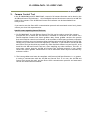
External appearance and dimensions ......................................... - 54 11.
Specifications ........................................................................ - 55 11.1
11.2
Spectral response ......................................................................... - 55 Specifications table ...................................................................... - 56 -
Appendix 1
1.
2.
2.1
2.2
2.3
2.4
Short ASCII Command Communication Protocol .................... - 58 -
Communication setting ..................................................................... - 58 Protocol(Short ASCII Command) ..................................................... - 58 Transmit the setting command to camera ......................................................... - 58 Transmit the request command to camera ........................................................ - 58 -
Switching baud rate between PC and camera ........................................ - 59 Command list (Short ASCII command) .................................................. - 59 -
2.4.1
2.4.2
2.4.3
2.4.4
2.4.5
2.4.6
2.4.7
2.4.8
2.4.9
2.4.10
2.4.11
GenCP Bootstrap Register .......................................................................... - 59
Technology Specific Bootstrap Register .......................................................... - 60
Device Control ........................................................................................ - 60
Image Format Control ............................................................................... - 61
Acquisition Control ................................................................................... - 62
Digital I/O Control ................................................................................... - 62
Analog Control ........................................................................................ - 64
LUT Control ........................................................................................... - 66
Transport Layer Control ............................................................................. - 66
User Set Control .................................................................................... - 66
JAI-Custom ........................................................................................... - 67
-
Appendix 2 ................................................................................... - 82 1.
2.
3.
4.
5.
6.
Precautions ..................................................................................... Typical Sensor Characteristics .............................................................. Caution when mounting a lens on the camera .......................................... Caution when mounting the camera....................................................... Exportation ..................................................................................... References...................................................................................... -
82 82 82 83 83 83 -
Manual change history ..................................................................... - 84 User's Record ................................................................................ - 85 -
- 5 -
EL-2800M-PMCL / EL-2800C-PMCL
Before using this manual
EMVA 1288
With regard to signal to noise ratio in this manual, specifications measured by EMVA 1288 are used
together with specifications by a traditional measurement method.
EMVA 1288 is a more complete measurement that considers multiple noise sources, including
random noise, pattern noise, and shading. Additionally, EMVA 1288 incorporates temporal variances
in pixel output by capturing 100 frames of data and computing the RMS variations over the captured
frames. Because of the comprehensive nature of the noise analysis and the additional consideration
for RMS variances over time, EMVA 1288 SNR measurements are inherently lower than the traditional
SNR measurements given by manufacturers. However, the comprehensive nature combined with
rigid test parameters, means that all manufacturers’ are measuring their products equally and EMVA
1288 tested parameters can be compared among different manufacturers’ products.
In order to learn more about EMVA 1288, please visit http://www.emva.org
Frame grabber board
The EL-2800-PMCL complies with “Power over Camera Link” which enables power to be supplied to
the camera through the Camera Link cable(s). Because the power requirements of the camera
exceed the amount of power which can be provided over a single PoCL connection, power must be
supplied via both Camera Link cables in order to utilize the PoCL capabilities. If you plan to use this
function, please be sure that the frame grabber board you are using also complies with this
specification. Alternatively, the camera can be powered via a separate power supply connected to
the 12-pin Hirose connector.
- 6 -
EL-2800M-PMCL / EL-2800C-PMCL
1. General
The EL-2800M-PMCL and EL-2800C-PMCL are the first new Elite Series cameras to be introduced.
They provide high picture quality, such as high sensitivity and low noise, suitable for machine vision
applications. The EL-2800M-PMCL is a monochrome progressive scan CCD camera and the
EL-2800C-PMCL is the equivalent Bayer mosaic progressive scan CCD camera. Both are equipped
with a 2/3-inch CCD sensor offering 2.83 million pixels resolution and a 4:3 aspect ratio. They
provide 54.7 frames per second for continuous scanning with 1920 x 1440 full pixel resolution for
both monochrome and raw Bayer output.
8-bit, 10-bit or 12-bit output can be selected for both monochrome and Bayer outputs. The
EL-2800C-PMCL is also capable of performing in-camera color interpolation to produce 24-bit (8-bit
per color) RGB output at 15.8 fps. Video output is via a Mini Camera Link interface supporting both
Base and Medium configurations. A full pixel readout, partial scan readout, or binning mode
(monochrome only) can be selected depending on the application.
EL-2800M-PMCL and EL-2800C-PMCL have various comprehensive functions needed for automated
optical inspection applications, such as solid state device inspection or material surface inspection.
They incorporate video processing functions such as a look-up table, flat field shading compensation
and blemish compensation in addition to fundamental functions such as trigger, exposure setting
and video level control.
As a common Elite Series feature, a new connector for lens control is employed. EL-2800M-PMCL
and EL-2800C-PMCL support P-iris and motor-driven lenses as standard lens control capabilities.
Factory options are available to configure this connector to support DC iris systems as well as
provide a video iris output signal, or to provide additional TTL IN and OUT lines.
The latest version of this manual can be downloaded from: www.jai.com
The latest version of the Camera Control Tool for the EL-2800M-PMCL and EL-2800C-PMCL can be
downloaded from: www.jai.com
For camera revision history, please contact your local JAI distributor.
2.
Camera composition
The standard camera composition is as follows.
Camera body
1
Sensor protection cap 1
Dear Customer (sheet) 1
The following optional accessories are available.
Tripod base
Power supply unit
MP-42
PD-12 series
- 7 -
EL-2800M-PMCL / EL-2800C-PMCL
3.
Main features
New Elite Series, 2/3 ” progressive scan camera
Utilizes Mini Camera Link interface with Base and Medium configurations
Aspect ratio 4:3, 1920 (h) x 1440 (v), 2.8 million effective pixels
4.54 μm square pixels
S/N 61dB for monochrome and 58.5 dB for color (traditional measurement)
8-bit, 10-bit or 12-bit output for monochrome and Bayer or 8-bit per color output for RGB color
54.7 frames/second with full resolution in continuous operation for 4-tap output (monochrome
or Bayer), 15.8 frames/second for 1-tap output (RGB output in-camera interpolation))
Various readout modes, including horizontal and vertical binning (EL-2800M-PMCL only) and ROI
(Region Of Interest) for faster frame rates
0dB to +30dB gain control for EL-2800M-PMCL and 0dB to +27dB for EL-2800C-PMCL
10 μs (1/100,000) to 8 seconds exposure control in 1 μs step
Auto exposure control
Timed and trigger width exposure control,
RCT, PIV and sequential trigger modes for specific applications
ALC control with combined function of AGC, auto exposure and auto iris
Various pre-processing circuits are provided
Programmable LUT
Gamma correction from 0.45 to 1.0
Flat field correction
Bayer white balance with manual or one-push auto (EL-2800C-PMCL only)
Bayer color interpolation (EL-2800C-PMCL only)
Blemish compensation
Auto iris lens video output with H-sync
New Hirose 10P connector for lens interface including P-Iris lens control
C-mount for lens mount
Setup by Windows XP/Vista/7 via serial communication
- 8 -
EL-2800M-PMCL / EL-2800C-PMCL
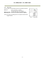
4.
Locations and functions
4.1
Locations and functions
Lens mount
10-pin AUX connector
LED
12-pin connector
Camera Link Connector 2
Camera Link Connector 1
Mounting hole
C-mount (Note *1)
Standard (Connector for lens control)
Indication for power and trigger input
DC+12V and trigger input
Digital video output (Medium configuration) (Note *2)
Digital video output (Base configuration) (Note *2)
M3 depth 5 mm for fixing the camera to the mount plate or
tripod mount plate (Note *3)
*1) Note: Rear protrusion on C-mount lens must be less than 10.0 mm.
*2) Note: When a Camera Link cable is connected to the camera, please do not excessively tighten
screws by using a driver. The Camera Link receptacle on the camera might be damaged.
For security, the strength to tighten screws is less than 0.147 Newton meter (Nm).
Tightening by hand is sufficient in order to achieve this.
*3) Note: The part number for the tripod adapter plate (with 1/4"-20 thread) is MP-42 (option).
Fig. 1
Locations
- 9 -
EL-2800M-PMCL / EL-2800C-PMCL
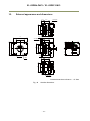
4.2. Rear Panel
The rear panel mounted LED provides the following information:
Amber:
Power connected – initiating
This light goes OFF after initiating.
Steady green: Camera is operating in Continuous mode
Flashing green: The camera is receiving external triggering
Note: The interval of flashing does not correspond with external
trigger duration.
Fig. 2
- 10 -
Rear panel
EL-2800M-PMCL / EL-2800C-PMCL
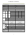
5. Input and output
5.1
Connectors and pin assignment
5.1.1
12-Pin connector
5.1.1.1
Figure
Type: HR10A-10R-12PB-01 (Hirose) male or equivalent.
Use the part number HR10A-10P-12S for the cable side
Fig.3
5.1.1.2
Hirose 12-pin connector
Pin assignment
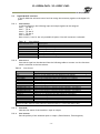
Table – 1 12P pin assignment
Pin no.
Signal
1
GND
2
DC input
3
4
5
6
7
8
9
10
11
12
Remarks
+12V to +24V
GND
Iris video
NC
NC
NC
NC
TTL out 1
TTL In 1
DC input
GND
Exclusive video output for auto iris
Line 1 (Note*1)
Line 4 (Note*2)
+12V to +24V
*1) Factory default setting is an Exposure Active signal with negative polarity.
*2) Factory default setting is a trigger input
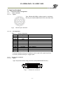
5.1.2
Camera Link connector
5.1.2.1
Figure
Type: 26-pin Mini Camera Link Connector (Honda HDR-EC26FYTG2-SL+)
1
13
26
Fig.4
14
Camera Link connector
- 11 -
EL-2800M-PMCL / EL-2800C-PMCL
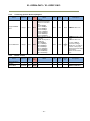
5.1.2.2
Pin assignment
Table – 2 Camera Link connector 1 Pin assignment
Pin No
In/Out
Name
1,26
Power
2(-),15(+)
O
TxOUT0
3(-),16(+)
O
TxOUT1
4(-),17(+)
O
TxOUT2
5(-),18(+)
O
TxClk
6(-),19(+)
O
TxOUT3
7(+),20(-)
I
SerTC (RxD)
8(-),21(+)
O
SerTFG (TxD)
9(-),22(+)
I
CC1 (Trigger)
10(+),23(-)
N.C
11,24
N.C
12,25
N.C
13,14
Shield
Table – 3 Camera Link connector 2 pin assignment
Pin No
In/Out
Name
1,26
Power
2(-),15(+)
O
TxOUT0
3(-),16(+)
O
TxOUT1
4(-),17(+)
O
TxOUT2
5(-),18(+)
O
TxClk
6(-),19(+)
O
TxOUT3
7(+),20(-)
I
N.C
8(-),21(+)
O
N.C
9(-),22(+)
I
N.C
10(+),23(-)
N.C
11,24
N.C
12,25
N.C
13,14
Shield
5.1.3
AUX Standard
Hirose 10-Pin Connector
Type : HIROSE 10-Pin Connector 3260-10S3(55)
8
1
Fig.5
Hirose 10P connector
- 12 -
Note
Power
Data out
Clock for CL
Data out
LVDS Serial Control
Trigger IN
Power return
Note
Power
Data out
Clock for CL
Data out
Power return
EL-2800M-PMCL / EL-2800C-PMCL
Table – 4
No
I/O
1
O
2
O
3
O
4
O
5
6
O
7
O
8
O
9
O
10
O
5.1.4
AUX Standard Hirose 10P connector pin assignment
Name
Note
DRIVE IRIS+
Motorized Lens
DRIVE FOCUS+
Motorized Lens
DRIVE ZOOM+
Motorized Lens
COMMON
Motorized Lens
GND
P-IRIS OUT1A
P-Iris Lens
P-IRIS OUT1B
P-Iris Lens
P-IRIS OUT2A
P-Iris Lens
P-IRIS OUT2B
P-Iris Lens
GND
AUX Type 2 Hirose 10-Pin Connector (Factory option)
HIROSE 10-Pin Connector 3260-10S3(55)
Note: This is a factory option.
Table – 5 AUX connector Type 2 pin assignment
No
I/O
Name
Note
1
O
Video Signal
Video Iris Lens
2
O
Power DC+12V
Video Iris Lens
3
NC
4
NC
5
GND
6
O
DC IRIS DAMPDC Iris
7
O
DC IRIS DAMP+
DC Iris
8
O
DC IRIS DRIVE+
DC Iris
9
O
DC IRIS DRIVEDC Iris
10
GND
5.1.5
AUX Type 3
Hirose 10-Pin Connector (Factory option)
HIROSE 10-Pin Connector 3260-10S3(55)
Note: This is a factory option.
Table – 6 AUX connector Type 3 pin assignment
No
I/O
Name
Note
1
O
TTL OUT2
Line8
2
O
TTL OUT3
Line9
3
I
TTL_IN2
Line10
4
NC
5
GND
6
I
LVDS_IN1+
Line11
7
I
LVDS_IN18
NC
9
GND
10
GND
- 13 -
EL-2800M-PMCL / EL-2800C-PMCL
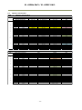
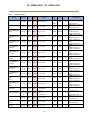
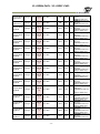
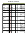
5.2
Camera Link interface
Table – 7
Camera Link interface
EL-2800M/C-PMCL
Port
D
i
g
i
t
a
l
I
/
O
1
Camera Link Configuration
Camera Link port/bit
GenICam Tap Geometry
Port A0
TxIN 0
Port A1
TxIN 1
Port A2
TxIN 2
Port A3
TxIN 3
Port A4
TxIN 4
Port A5
TxIN 6
Port A6
TxIN 27
Port A7
TxIN 5
Port B0
TxIN 7
Port B1
TxIN 8
Port B2
TxIN 9
Port B3
TxIN 12
Port B4
TxIN 13
Port B5
TxIN 14
Port B6
TxIN 10
Port B7
TxIN 11
Port C0
TxIN 15
Port C1
TxIN 18
Port C2
TxIN 19
Port C3
TxIN 20
Port C4
TxIN 21
Port C5
TxIN 22
Port C6
TxIN 16
Port C7
TxIN 17
TxIN 24
TxIN 25
(Port I0)
TxIN 26
(Port I1)
TxIN 23
Base
1Tap / 12bit
1X1 - 1Y
Tap1 D0
Tap1 D1
Tap1 D2
Tap1 D3
Tap1 D4
Tap1 D5
Tap1 D6
Tap1 D7
Tap1 D8
Tap1 D9
Tap1 D10
Tap1 D11
2ap / 12bit
1X - 2YE/1X2-1Y
Tap 1 D0
Tap 1 D1
Tap 1 D2
Tap 1 D3
Tap 1 D4
Tap 1 D5
Tap 1 D6
Tap 1 D7
Tap 1 D8
Tap 1 D9
Tap 1 D10
Tap 1 D11
Tap 2 D8
Tap 2 D9
Tap 2 D10
Tap 2 D11
Tap 2 D0
Tap 2 D1
Tap 2 D2
Tap 2 D3
Tap 2 D4
Tap 2 D5
Tap 2 D6
Tap 2 D7
LVAL
FVAL
DVAL
Exposure Active
LVAL
FVAL
DVAL
Exposure Active
Medium
4 Tap / 12bit
1x2 - 2YE
Tap 1 D0
Tap 1 D1
Tap 1 D2
Tap 1 D3
Tap 1 D4
Tap 1 D5
Tap 1 D6
Tap 1 D7
Tap 1 D8
Tap 1 D9
Tap 1 D10
Tap 1 D11
Tap 2 D8
Tap 2 D9
Tap 2 D10
Tap 2 D11
Tap 2 D0
Tap 2 D1
Tap 2 D2
Tap 2 D3
Tap 2 D4
Tap 2 D5
Tap 2 D6
Tap 2 D7
LVAL
FVAL
DVAL
Exposure Active
Base
1 Tap / 8bit
RGB
RD 0
RD 1
RD 2
RD 3
RD 4
RD 5
RD 6
RD 7
G D2
G D3
G D4
G D5
G D6
G D7
G D8
G D9
B D2
B D3
B D4
B D5
B D6
B D7
B D8
B D9
LVAL
FVAL
DVAL
Exposure Active
Medium
4 Tap / 12bit
1x2 - 2YE
Tap 4 D0
Tap 4 D1
Tap 4 D2
Tap 4 D3
Tap 4 D4
Tap 4 D5
Tap 4 D6
Tap 4 D7
Tap 3 D0
Tap 3 D1
Tap 3 D2
Tap 3 D3
Tap 3 D4
Tap 3 D5
Tap 3 D6
Tap 3 D7
Tap 3 D8
Tap 3 D9
Tap 3 D10
Tap 3 D11
Tap 4 D8
Tap 4 D9
Tap 4 D10
Tap 4 D11
LVAL
FVAL
DVAL
Exposure Active
Base
1 Tap / 8bit
RGB
—
—
—
—
—
—
—
—
—
—
—
—
—
—
—
—
—
—
—
—
—
—
—
—
—
—
—
—
EL-2800M/C-PMCL
Port
D
i
g
i
t
a
l
I
/
O
2
(
1
/
2
)
Camera Link Configuration
Camera Link port/bit
GenICam Tap Geometry
Port D0
TxIN 0
Port D1
TxIN 1
Port D2
TxIN 2
Port D3
TxIN 3
Port D4
TxIN 4
Port D5
TxIN 6
Port D6
TxIN 27
Port D7
TxIN 5
Port E0
TxIN 7
Port E1
TxIN 8
Port E2
TxIN 9
Port E3
TxIN 12
Port E4
TxIN 13
Port E5
TxIN 14
Port E6
TxIN 10
Port E7
TxIN 11
Port F0
TxIN 15
Port F1
TxIN 18
Port F2
TxIN 19
Port F3
TxIN 20
Port F4
TxIN 21
Port F5
TxIN 22
Port F6
TxIN 16
Port F7
TxIN 17
TxIN 24
(Port I2)
TxIN 25
(Port I3)
TxIN 26
(Port I4)
TxIN 23
Base
1Tap / 12bit
1X1 - 1Y
—
—
—
—
—
—
—
—
—
—
—
—
—
—
—
—
—
—
—
—
—
—
—
—
—
—
—
—
2ap / 12bit
1X - 2YE/1X2-1Y
—
—
—
—
—
—
—
—
—
—
—
—
—
—
—
—
—
—
—
—
—
—
—
—
—
—
—
—
- 14 -
EL-2800M-PMCL / EL-2800C-PMCL
5.3
Digital IN/OUIT interface
In the EL-2800 the software control tool can assign the necessary signals to the digital I/O
ports.
5.3.1
Line Selector
In the Line Selector, the following input and output signals can be assigned.
Line 1 TTL Out 1
Line 7 TTL In 1
Line 8 TTL Out 2
Line 9 TTL Out 3
Line 11 LVDS In
Note: Lines 8, 9 and 11 are only available if Option 2 for AUX connector is selected.
Table – 8
Line selector
Line Selector item
Description
Line 1 TTL 1 Out
Line 8 TTL 2 Out
Line 9 TTL 3 Out
NAND 0 In 1
NAND 0 In 2
NAND 1 In 1
NAND 1 In 2
5.3.2
TTL 1 output from # 9 pin of HIROSE 12 Pin on the rear
TTL 2 output from #1 pin of AUX connector on the rear
TTL 2 output from #2 pin of AUX connector on the rear
First input to a first gate of NAND
Second input to a first gate of NAND
First input to a second gate of NAND
Second input to a second gate of NAND
Line source
Line source signal can be selected from the following table to connect it to the line item
which is selected in the line selector.
Table-9
Line Source
Line Source item Description
Low
High
Frame Trigger Wait
Frame Active
Exposure Active
FVAL
LVAL
PulseGenerator0 Out
PulseGenerator1 Out
PulseGenerator2 Out
PulseGenerator3 Out
TTL 1 In
CL CC1 In
Nand0 Out
Nand1 Out
Line 10 TTL 2 In
Line 11 LVDS 1 In
Connect Low Level signal to line item selected in Line Selector, Default setting
Connect Low High signal to line item selected in Line Selector
Connect Frame Trigger Wait signal to line item selected in Line Selector
Connect Frame Active signal to line item selected in Line Selector
Connect Exposure Active signal to line item selected in Line Selector
Connect FVAL signal to line item selected in Line Selector
Connect LVAL signal to line item selected in Line Selector
Connect Pulse Generator 0 signal to line item selected in Line Selector
Connect Pulse Generator 1 signal to line item selected in Line Selector
Connect Pulse Generator 2 signal to line item selected in Line Selector
Connect Pulse Generator 3 signal to line item selected in Line Selector
Connect TTL 1 IN signal to line item selected in Line Selector
Connect CL CC1 IN signal to line item selected in Line Selector
Connect NAND 0 signal to line item selected in Line Selector
Connect NAND 1 signal to line item selected in Line Selector
Connect TTL 2 IN signal to Line 10 (Factory option)
Connect LVDS 1 IN signal to Line 11 (Factory option)
Note) As for LVAL, some line items cannot be connected. Refer to“5.4.6.2 GPIO matrix table”
5.3.3
Line Mode
Indicates the status of the interface, input or output.
5.3.4
Line Inverter
Sets the polarity of the selected input or output. (False=Positive, True=Negative)
- 15 -
EL-2800M-PMCL / EL-2800C-PMCL
5.3.5
Line Status
Indicates the status of the selected signal, input or output (True=High or False=Low)
5.3.6
Line Format
Indicates the current interface of the selected line item, input or output.
Input
CC1 In
Line 4
TTL In 1
Line 7
Output TTL Out1
Line 1
5.3.7
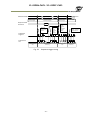
GPIO
This is a general interface for input and output and controls input and output for trigger
signals or valid signals and pulse generators. By using this interface, you can control an
external light source, make a delayed function to input a trigger signal or make a precise
exposure control with PWC trigger.
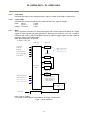
Basic block diagram is as follows.
EL-2800M/C-PMCL GPIO
Sel Bit (5,0)
Sel Bit (7)
Soft Trigger
LVAL IN
INV
GPIO 1 (TTL OUT 1)
GPIO 8 (TL OUT 2)
GPIO 9 (TTL OUT 3)
FVAL IN
Exposure Active
Frame Trigger Wait
Frame Active
Sel Bit (7)
INV
INV N
Cross Point
Switch
Gate 1
Gate 2
NAND
Sel Bit (7)
INV
Non INV
GPIO 4 (TTL IN 1)
Pulse
Pulse
Pulse
Pulse
GPIO 7 (CL CC1)
GPIO 10 (TTL IN2)
GPIO 11 (LVDS IN)
Generator
Generator
Generator
Generator
0
1
2
3
Pulse Generator
20 bit counter x 4
CLR
Pixel Clock
12 bit Counter
Pixel Clock is 54 MHz.
I/F written in blue letters is available if AUX Type 3 is selected.
Fig.6 GPIO interface
- 16 -
EL-2800M-PMCL / EL-2800C-PMCL
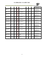
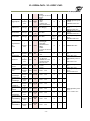
The following table shows the input and output matrix.
Table – 10
GPIO input and output matrix
Pulse
Generator
Selector
LS2
Line 9 - TTL 3 Out(※)
ND0IN1
NAND 0 In 1
ND0IN2
NAND 0 in 2
ND1IN1
NAND 1 In 1
ND1IN2
NAND 1 in 2
PGIN0
Pulse Generator 0
PGIN1
Pulse Generator 1
Low
○
○
○
○
○
○
○
○
○
○
○
○
HIGH
○
○
○
○
○
○
○
○
○
○
○
○
Soft Trigger
○
Frame Trigger Wait
○
○
○
○
○
○
○
○
○
○
○
Frame Active
○
○
○
○
○
○
○
○
○
○
○
Exposure Active
○
○
○
○
○
○
○
○
○
○
○
FVAL
○
○
○
○
○
○
○
○
○
○
○
○
○
○
○
○
○
○
○
○
Source Signal
(Cross Point Switch Input)
PGIN2
Pulse Generator 2
PGIN3
Pulse Generator 3
LS1
Line 8 - TTL 2 Out(※)
Line
Selector
LS0
Line1 - 12Pin TTL Out
Trigger
Selector
Trigger Source
(Frame Start Trig Source)
Selector
(Cross Point
Switch Output)
○
○
○
PulseGenerator0
○
○
○
○
○
○
○
○
PulseGenerator1
○
○
○
○
○
○
○
○
○
PulseGenerator2
○
○
○
○
○
○
○
○
○
○
PulseGenerator3
○
○
○
○
○
○
○
○
○
○
○
TTL_In1
○
○
○
○
○
○
○
○
○
○
○
○
CL_CC1_In
○
○
○
○
○
○
○
○
○
○
○
○
Nand0 Out
○
○
○
○
○
○
○
○
○
○
Nand1 Out
○
○
○
○
○
○
○
○
○
○
Line 10 - TTL 2 In (※)
○
○
○
○
○
○
○
○
○
○
○
○
Line 11 - LVDS 1 In(※)
○
○
○
○
○
○
○
○
○
○
○
○
LVAL
Trigger
Source
Line
Source
○
Pulse
Generator
Clear
Source
Note: Items with (※) are available if AUX Type 3 is selected.
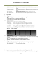
5.4
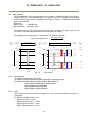
Pulse Generator
The EL-2800M/C-PMCL has a frequency divider using the pixel clock as the basic clock and
four pulse generators. In each Pulse Generator, various Clear settings are connected to GPIO.
The following shows Pulse Generator default settings.
- 17 -
EL-2800M-PMCL / EL-2800C-PMCL
Table - 11
Pulse Generator default settings
Display Name
Clock Pre-scaler
Value
1
Pulse Generator
Length Start
Point
End
Repeat
Clear
Clear
Clear
Clear
Pulse Generator
Point
Count
Source
Inverter
Activation
Sync
Selector
Mode
1
0
1
0
Off
True
Off
Async Mode
- Pulse Generator 0
- Pulse Generator 1
1
0
1
0
Off
True
Off
Async Mode
1
0
1
0
Off
True
Off
Async Mode
- Pulse Generator 2
- Pulse Generator 3
1
0
1
0
Off
True
Off
Async Mode
Note:]
When Pulse Generator Repeat Count is set to “0”, the camera is operating in Free Running mode.
However, based on the above default settings (Length=1, Start Point=0 and End Point=1), Pulse Generator stops at
High output. Therefore, if Start Point=0 and End Point=1 are configured, Length should be “2” as the minimum active
width.
5.4.1
Clock Pre-scaler
Clock pre-scaler (Divide Value) can set the dividing value of the frequency divider
(12-bit length) and the pixel clock is used for this. Four built-in pulse generators
work by the same clock. In the EL-2800M/C-PMCL, the pixel clock is 54 Mhz.
5.4.2
Pulse Generator Selector
This is where you select one of the 4 pulse generators in order to set or modify its
parameters.
Table - 12
Pulse Generator setting
Trigger Selector
Description
item
Pulse Generator
0
Pulse Generator
1
Pulse Generator
2
Pulse Generator
3
If Pulse Generator 0 is selected, Length、Start Point、End Point、Repeat Count、Clear Source、
Clear Inverter, Clear Activation and Clear Sync Mode of pulse generator 0 are displayed under the
selector.
If Pulse Generator 1 is selected, Length、Start Point、End Point、Repeat Count、Clear Source、
Clear Inverter, Clear Activation and Clear Sync Mode of pulse generator 1 are displayed under the
selector.
If Pulse Generator 2 is selected, Length、Start Point、End Point、Repeat Count、Clear Source、
Clear Inverter, Clear Activation and Clear Sync Mode of pulse generator 2 are displayed under the
selector.
If Pulse Generator 3 is selected, Length、Start Point、End Point、Repeat Count、Clear Source、
Clear Inverter, Clear Activation and Clear Sync Mode of pulse generator 3 are displayed under the
selector.
- 18 -
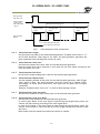
EL-2800M-PMCL / EL-2800C-PMCL
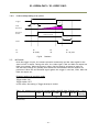
Pulse generator
Clear source IN
(Clear activation
= Rising edge
Clear SYNC mode
= Async)
Pulse generator repeat count = N
(Pulse generator length x N)
Pulse generator
length
Pulse generator
length
Pulse generator
length
Pulse generator
Output
0
0
0
Pulse generator End point
Pulse generator Start point
Fig.7
Pulse Generator Pulse construction
5.4.3
Pulse Generator Length
Set the counter up value for the selected pulse generator. If Repeat Count value is “0”,
and if Pulse Generator Clear signal is not input, the pulse generator generates the
pulse repeatedly until reaching this counter up value.
5.4.4
Pulse Generator Start Point
Set the active output start count value for the selected pulse generator.
However, please note that a maximum 1 clock jitter for the clock which is divided in the
clock pre-scaler can occur.
5.4.5
Pulse Generator End Point
Set the active output ending count value for the selected pulse generator.
5.4.6
Pulse Generator Repeat Count
Set the repeating number of the pulse for the selected pulse generator. After Trigger
Clear signal is input, the pulse generator starts the count set in Repeat Count.
Accordingly, an active pulse which has a start point and end point can be output
repeatedly.
However, if Repeat Count is set to“0”, it works as Free Running counter.
5.4.7
Pulse Generator Clear Activation
Set the clear conditions of clear count pulse for the selected pulse generator.
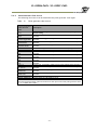
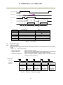
5.4.8
Pulse Generator Clear Sync Mode
Set the count clear method for the selected pulse generator.
In case of Async Mode, if the clear signal is input during the length setting value, the
counter will stop counting according to the clear signal input.
In case of Sync Mode, if the clear signal is input during the length setting value, the
counter will continue to count until the end of the length setting value and then clear
the count.
Both modes clear the repeat count when the counter is cleared.
- 19 -
EL-2800M-PMCL / EL-2800C-PMCL
(Example1) Clear Activation = Rising Edge, Clear Sync Mode = Async Mode,
Clear Inverter = False
Pulse
Generator
Clear Source In
Pulse
Generator
Output
Clear
↓
0
Fig.8
Counter clear in Async mode
(Example2) Clear Activation = Rising Edge, Clear Sync Mode = Sync Mode,
Clear Inverter = False
Pulse
Generator
Clear Source In
Pulse
Generator
Output
Clear
↓
0
Pulse
Generator
Length
0
Fig.9
Note: Repeat Count is also reset.
Counter clear in Sync mode
- 20 -
EL-2800M-PMCL / EL-2800C-PMCL
5.4.9
Pulse Generator Clear Source
The following clear source can be selected as the pulse generator clear signal.
Table - 13
Pulse generator clear source
Pulse Generator
Clear Source
item
Low
High
Frame Trigger Wait
Frame Active
Exposure Active
FVAL
LVAL
PulseGenerator0
Out
PulseGenerator1
Out
PulseGenerator2
Out
PulseGenerator3
Out
TTL 1 In
CL CC1 In
Nand0 Out
Nand1 Out
Description
Connect Low level signal to Clear Source for the selected pulse generator.
Default setting
Connect High level signal to Clear Source for the selected pulse
generator.
Connect Frame Trigger Wait signal to Clear Source for the selected pulse
generator.
Connect Frame Active signal to Clear Source for the selected pulse
generator.
Connect Exposure Active signal to Clear Source for the selected pulse
generator.
Connect FVAL signal to Clear Source for the selected pulse generator.
Connect LVAL signal to Clear Source for the selected pulse generator.
Connect Pulse Generator 0 output to Clear Source for the selected pulse
generator.
Connect Pulse Generator 1 output to Clear Source for the selected pulse
generator.
Connect Pulse Generator 2 output to Clear Source for the selected pulse
generator.
Connect Pulse Generator 3 output to Clear Source for the selected pulse
generator.
Connect TTL 1 IN signal to Clear Source for the selected pulse generator.
Connect CL CC1 IN signal to Clear Source for the selected pulse
generator.
Connect NAND 0 output signal to Clear Source for the selected pulse
generator.
Connect NAND 1 output signal to Clear Source for the selected pulse
generator.
Connect TTL 2 IN signal to LINE 10.
Connect LVDS 11 1 IN signal to Line 11
Line 10 TTL 2 In
Line 11 LVDS 1 In
Note:
The pulse generator output cannot be used as the clear input to the same pulse generator. Refer
to “5.3.7 GPIO matrix table”.
- 21 -
EL-2800M-PMCL / EL-2800C-PMCL
5.4.10
Pulse Generator Inverter
Clear Source Signal can have polarity inverted.
5.4.11
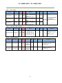
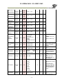
Pulse Generator Setting table
Table - 14
Pulse Generator setting parameters
Display Name
Value
Clock Pre-scaler
Pulse Generator Clock (MHz)
Pulse Generator Selector
1 to 4096
[Pixel Clock:54MHz]÷[Clock Pre-scaler]
- Pulse Generator 0
- Pulse Generator 1
- Pulse Generator 2
- Pulse Generator 3
1 to 1048575
([Clock Source]÷[Clock Pre-scaler])-1 x [Pulse Generator Length]
[ Pulse Generator Length (ms)]-1
0 to 1048574
([Clock Source]÷[Clock Pre-scaler])-1 x [Pulse Generator Start Point]
1 to 1048575
([Clock Source]÷[Clock Pre-scaler])-1 x [Pulse Generator End Point]
[ Pulse Generator End Point (ms)]-[ Pulse Generator Start Point (ms)]
0 to 255
- Off
- High Level
- Low level
- Rising Edge
- Falling Edge
- Async mode
- Sync mode
- Low
- High
- Frame Trigger Wait
- Frame Active
- Exposure Active
- FVAL
- LVAL
- PulseGenerator0
- PulseGenerator1
- PulseGenerator2
- PulseGenerator3
- TTL_In1
- CL_CC1_In
- Nand0 Out
- Nand1 Out
- Line 10 - TTL 2 In
- Line 11 - LVDS 1 In
- False
- True
- Pulse Generator Length
- Pulse Generator Length (ms)
- Pulse Generator Frequency (Hz)
- Pulse Generator Start Point
- Pulse Generator Start Point (ms)
- Pulse Generator End Point
- Pulse Generator End Point (ms)
- Pulse Generator pulse-width (ms)
- Pulse Generator Repeat Count
- Pulse Generator Clear Activation
Clear Mode for the Pulse Generators
- Pulse Generator Clear Sync Mode
- Pulse Generator Clear Source
- Pulse Generator Inverter(Polarity)
Pulse Generator Clear Inverter
Note:
1. If Pulse Generator Repeat Count is set to “0”, the pulse generator works in Free Running mode.
- 22 -
EL-2800M-PMCL / EL-2800C-PMCL
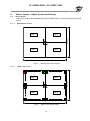
6.
Sensor layout, output format and timing
6.1
Sensor layout
CCD sensors used in the EL-2800M-PMCL and EL-2800C-PMCL have the following tap and pixel
layout.
Monochrome sensor
Tap 3
F
Tap 1
Tap 4
1440 Pixels
6.1.1
Tap 2
1920 Pixels
Fig.10
Bayer color sensor
Tap 3
F
Tap 1
Tap 4
1440 Pixels
6.1.2
Monochrome sensor layout
Tap 2
1920 Pixels
Fig.11
Bayer color sensor layout
- 23 -
EL-2800M-PMCL / EL-2800C-PMCL
6.2.
Camera output format
The EL-2800M-PMCL and EL-2800C-PMCL have the following camera output formats
described in GenICam SFNC Ver.1.5.1 as Tap Geometry.
Table – 15 Camera output format
Camera output format
1X–1Y
1X–2YE
1X2–1Y
1X2–2YE
24-bit RGB (8-bit x 3) (1X–1Y)
6.2.1
Tap geometry
Single tap
Dual tap
Dual tap
Four tap
Single tap
Reference figure
6.2.1
6.2.2
6.2.3
6.2.4
6.2.1
1X-1Y
1X–1Y is defined in GenICam SFNC Ver.1.5.1 for 1-tap readout and the readout system
is the following.
Step X = 1
Tap 1
X1
Y1
X2
Y1
X3
Y1
X4
Y1
X5
Y1
X6
Y1
X7
Y1
X8
Y1
X1913
Y1
X1914
Y1
19115
Y1
X1916
Y1
X1917
Y1
X1918
Y1
X1919
Y1
X1
Y2
X5120
X1920
Y1
Y1
1440 Pixel
720 Pixel x 2 Tap
X1920
Y2
Step Y = 1
X1
Y1439
X1
1440
X1920
Y1439
X2
Y1440
X3
Y1440
X4
Y1440
X5
Y1440
X6
Y1440
X7
Y1440
X8
Y1440
1920 Pixel
X1913
Y1440
X1914
Y1440
X1915
Y1440
X1916
Y1440
X1917
Y1440
X1918
Y1440
X1919
Y1440
X5120
X1920
Y1440
Y3840
860 Pixel x 2Tap
X1
Y3840
Fig.12
1X–2YE
1X–2YE is for 2-tap readout and the readout system is as follows.
Step X = 1
Tap 1
X1
Y1
X2
Y1
X3
Y1
X4
Y1
X5
Y1
X6
Y1
X7
Y1
X8
Y1
X1913
Y1
X1914
Y1
19115
Y1
X1916
Y1
X1917
Y1
X1918
Y1
X1919
Y1
X1
Y2
X5120
X1920
Y1
Y1
X1920
Y2
X1920
Y1220
X1920
Y1221
Step Y = 1
X1
Y1439
X1
1440
X1920
Y1439
X2
Y1440
X3
Y1440
X4
Y1440
X5
Y1440
X6
Y1440
X7
Y1440
X8
Y1440
X1913
Y1440
X1914
Y1440
X1915
Y1440
X1916
Y1440
X1917
Y1440
Tap 2
1920 Pixel
Fig.13
860 Pixel x 2Tap
1X–2YE readout
- 24 -
X1918
Y1440
X1919
Y1440
X5120
X1920
Y1440
Y3840
720 Pixel x 2 Tap
Step Y = 1
X1
Y1220
X1
Y1221
1440 Pixel
6.2.2
1X–1Y readout
EL-2800M-PMCL / EL-2800C-PMCL
6.2.3
1X2–1YE
1X2–1YE is also for 2-tap readout but the readout system is right and left as below.
Step X = 2
Tap 1
Tap 2
X1
Y1
X2
Y1
X3
Y1
X4
Y1
X5
Y1
X6
Y1
X7
Y1
X8
Y1
X1913
Y1
X1914
Y1
19115
Y1
X1916
Y1
X1917
Y1
X1918
Y1
X1919
Y1
X1
Y2
X5120
X1920
Y1
Y1
1440 Pixel
720 Pixel x 2 Tap
X1920
Y2
Step Y = 1
X1
Y1439
X1
1440
X1920
Y1439
X2
Y1440
X3
Y1440
X4
Y1440
X5
Y1440
X6
Y1440
X7
Y1440
X8
Y1440
X1913
Y1440
X1914
Y1440
X1915
Y1440
X1916
Y1440
X1917
Y1440
X1918
Y1440
X1919
Y1440
X5120
X1920
Y1440
Y3840
1920 Pixel
Fig.14
1X2–2YE
1X2–2YE is 4-tap readout and reads out electronic charges up and down and right and
left.
Step X = 2
Tap 1
Tap 2
X1
Y1
X2
Y1
X3
Y1
X4
Y1
X5
Y1
X6
Y1
X7
Y1
X8
Y1
X1913
Y1
X1914
Y1
19115
Y1
X1916
Y1
X1917
Y1
X1918
Y1
X1919
Y1
X1
Y2
X5120
X1920
Y1
Y1
X1920
Y2
X1920
Y1220
X1920
Y1221
Step Y = 1
X1
Y1439
X1
1440
X1920
Y1439
X2
Y1440
X3
Y1440
X4
Y1440
X5
Y1440
X6
Y1440
X7
Y1440
X8
Y1440
X1913
Y1440
X1914
Y1440
X1915
Y1440
X1916
Y1440
X1917
Y1440
Tap 3
Tap 4
1920 Pixel
Fig.15
860 Pixel x 2Tap
1X2–2YE readout
- 25 -
X1918
Y1440
X1919
Y1440
X5120
X1920
Y1440
Y3840
720 Pixel x 2 Tap
Step Y = 1
X1
Y1220
X1
Y1221
1440 Pixel
6.2.4
1X2–1YE readout
EL-2800M-PMCL / EL-2800C-PMCL
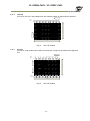
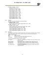
6.3
Output timing
6.3.1
Horizontal timing
6.3.1.1
Output format
1X2-2YE , 1X2–1Y
a) Vertical binning OFF
LVAL
102
DVAL
Video
(Tap 1, 2/Tap 3,4)
OB
OB
411Clk = Exposure Start Line
OB
20
5
960
5
20
305Clk = Other line
Exposure Active
(Exposure Start Line)
1421Clk = Exposure Start Line
1315Clk = Other Line
Fig.16
Horizontal Timing (Vertical timing OFF)
b) Vertical binning ON
LVAL
102
DVAL
Video
(Tap 1, 2/Tap 3,4)
OB
OB
665Clk = Exposure Start Line
20
OB
5
960
5
20
572Clk = Other line
Exposure Active
(Exposure Start Line)
1675Clk = Exposure Start Line
1582Clk = Other Line
Fig. 17
6.3.1.2
Output format
Horizontal timing (Vertical binning ON)
1X–2YE , 1X–1Y
a) Vertical binning OFF
LVAL
102
DVAL
Video
(Tap 1/Tap 2)
OB
OB
370Clk = Exposure Start Line
40
OB
10
1920
276Clk = Other line
Exposure Active
(Exposure Start Line)
2390Clk = Exposure Start Line
2296Clk = Other Line
Fig.18
Horizontal timing (Vertical binning OFF)
- 26 -
10 40
EL-2800M-PMCL / EL-2800C-PMCL
b) Vertical binning ON
LVAL
102
DVAL
Video
(Tap 1/Tap 2)
OB
OB
625Clk = Exposure Start Line
40
OB
10
1920
10 40
532Clk = Other line
Exposure Active
(Exposure Start Line)
2645Clk = Exposure Start Line
2552Clk = Other Line
Fig.19
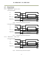
6.3.2
6.3.2.1
Horizontal timing (Vertical binning ON)
Vertical timing
Output format
1X2–2YE , 1X–2YE
a) Vertical binning OFF
FVAL
18L
720L
6L(Min)
DVAL
8L
10L
Video Tap1
OB
1,2,3,
Video Tap2
OB
1460,1459 1449,1448,1447
Fig.20
11,12,13
728,729,730
733,732,731
Vertical Timing (Vertical timing OFF)
b) Vertical binning ON
FVAL
9L
360L
6L(Min)
DVAL
4L
5L
Video Tap1
OB
1+2,3+4, 11+12,13+14
727+728,729+730
Video Tap2
OB
1460+1459 1449+1448,1447+1446
734+733,732+731
Fig. 21
Vertical timing (Vertical binning ON)
- 27 -
EL-2800M-PMCL / EL-2800C-PMCL
6.3.2.2
Output format
1X2–1Y , 1X–1Y
a) Vertical binning OFF
FVAL
18L
1440L
18L
6L(Min)
DVAL
8L
Video Tap1
OB
Fig.22
10L
1,2,3
11,12,13
1447,1448,1449
10L
8L
1459,1460
OB
Vertical timing (Vertical binning OFF)
b) Vertical binning ON
FVAL
9L
720L
9L
9L(Min)
DVAL
Video Tap1
4L
5L
OB
1+2,3+4,
Fig.23
1446+1447,1448+1449 1459+1460
4L
OB
Vertical timing (Vertical binning ON)
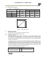
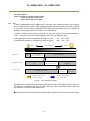
ROI (Region Of Interest)
In the EL-2800M-PMCL and EL-2800C-PMCL, a subset of the image can be output by setting
Height and Offset-Y in the Image Format Control section of the control tool. As the height is
decreased, the number of lines read out is decreased and as the result, the frame rate is
increased. The frame rate depends on the tap geometry and whether vertical binning is off
or on. See section 7.1.2 for formulas that can be used to calculate the maximum frame rate
for a specific ROI.
ROI can be set from 8 lines to 1440 lines in one-line increments for the EL-2800M-PMCL, or
in two-line increments for the EL-2800C-PMCL.
Offset_Y
Height Max
6.3.3
5L
11+12,13+14
Height
Width Max
Fig. 24
ROI setting
- 28 -
EL-2800M-PMCL / EL-2800C-PMCL
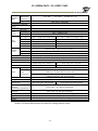
6.4
Digital output bit allocation
Table – 16
CCD out
Output level
Black
Monochrome
Color
Monochrome
Color
Analog Out
(equivalent)
Setup 3.6%,
25mV
0%
574mV
386mV
662mV
445mV
8bit
Digital Out
10bit
12bit
8LSB
32LSB
128LSB
100%
700mV
222LSB
890LSB
3560LSB
115%
808mV
255LSB
1023LSB
4095LSB
1023
White Clip Level
890
Digital Out [LSB]
100% Level
32
0
Black Level
25
Fig.25
7.
Analog Out [mV]
700 800
Bit allocation (10-bit)
Operating modes
The following controls are related to capturing the image.
7.1.
7.1.1
Acquisition control (change the frame rate)
Acquisition frame rate
With Trigger OFF (free running mode – see section 7.2.1), the default frame rate of the
camera is based on the specified ROI. The smaller the ROI, the faster the default frame
rate. However, it is possible to specify a free-running frame rate (i.e., no trigger needed)
that is slower than the default rate. This can be useful when a longer exposure time is
needed for a specific ROI.
To change the frame rate, the user may modify the default value which is displayed in the
AcquisitionFrameRate control based on the ROI specified. The user can type a number
corresponding to the desired frame rate or move the slider control to the appropriate value.
Allowed values range from the ROI’s default fastest frame rate to a rate of 0.125 frames
per second (8 seconds per frame). If the value entered is faster than the default frame rate,
the setting is ignored and the default frame rate is used
The setting range in Acquisition Frame Rate is:
Fastest
to
Slowest
Maximum frame rate based
on the area set by Image
to
0.125 Hz = 8 seconds/frame
Format Control (ROI)
How to set:
- 29 -
EL-2800M-PMCL / EL-2800C-PMCL
ROI should be set first using Height and Offset Y settings in Image Format Control.
The number shown in Acquisition Frame Rate (RAW) will correspond to the fastest frame
rate for the specified ROI.
The value can be adjusted as low as 0.125 fps (8 seconds per frame).
If ROI is changed from a smaller size to a larger size, the default frame rate of the ROI is
automatically recalculated inside the camera and changed to the slower frame rate of the
larger ROI.
7.1.2 Calculation of default frame rate
a) V Binning Off
1X2-2YE(fps) = 1/〔
[ Height/2 + {((720-(Height/2)-1)/4} + 25 ]× Line rate 〕
1X2-1Y(fps) = 1/【
〔 Height + {(OffsetY-1)/4} + [{1440-(OffestY + Height)}/9] + 46 〕
× Line rate】
1X-2YE(fps) = 1/〔
[ Height/2 + {((720-(Height/2)-1)/4} + 25 ]× Line rate 〕
1X-1Y(fps)
= 1/【
〔 Height + {(OffsetY-1)/7} + [{1440-(OffestY + Height)}/15] + 46 〕
× Line rate】
b) V Binning On
1X2-2YE(fps) = 1/〔
[ (Height/4) + {((360-(Height/4)-1)/2} + 16 ]× Line rate 〕
1X2-1Y(fps) = 1/【
〔 (Height/2)+ {(OffsetY-1)/2} + [{720-(OffsetY + (Height/2))}/4.5] + 28 〕
× Line rate】
1X-2YE(fps) = 1/〔
[ (Height/4)+ {((360-(Height/4)-1)/4} + 16 ]× Line rate 〕
1X-1Y(fps)
= 1/【
〔 (Height/2)+ {(OffsetY-1)/4} + [{720-(OffsetY + (Height/2))}/8] + 33 〕
× Line rate】
where,
Line rate
a) V Binning Off
1X2-2YE = 24.574us
1X2-1Y = 24.574us
1X-2YE = 42.519us
1X-1Y
= 42.519us
b) V Binning On
1X2-2YE = 29.296us
1X2-1Y = 29.296us
1X-2YE = 47.259us
1X-1Y
= 47.259us
7.2. Exposure control
7.2.1
Exposure Mode
Exposure Mode sets which exposure mode is to be used.
If the trigger is used, Frame Start must also be used.
When Exposure Mode is set to Timed or Trigger Width, the combination of Exposure Mode
and Frame Start can set various operations.
The following table shows the operation depending on the combination.
- 30 -
EL-2800M-PMCL / EL-2800C-PMCL
Table – 17
Exposure mode
Trigger Control
Exposure Mode
Frame Start
OFF
OFF or ON
Timed (EPS)
Timed(RCT)
Timed (PIV)
OFF
Trigger OFF
Trigger ON
Behavior
Self-running
No exposure
control
Self-running
Exposure control
available
-
-
ON
-
Operate in EPS,
RCT or PIV
OFF
Self-running
No exposure
control
-
ON
-
Exposure control
by trigger width
Trigger Width
Frame Start trigger: Sets whether the start of the frame is controlled externally or not.
Trigger Mode ON: If Acquisition Active is active and Exposure Mode chooses Timed or
Trigger Width, the exposure will be started by using the signal set
in Frame Trigger as the trigger.
Trigger Mode OFF: If Acquisition Active is active, the camera operates in free-running mode.
Exposure Mode can be selected from the following.
OFF:
No shutter control
Timed:
The exposure will be set in advance. The setting can be done in μsec
units.
Frame Start OFF: Free-running mode and exposure control is available.
Frame Start ON: EPS operation mode
In this status, if RCT or PIV is selected in Trigger option, the camera will
operate in RCT or PIV mode.
Trigger Width :
The exposure will be controlled by the width of the trigger pulse.
Frame Start OFF: Not active. No exposure control
Frame Start ON: PWC operation mode
7.2.2
Exposure Time
This command is effective only when Exposure Mode is set to Timed. It is for setting
exposure time.
The setting step for exposure time is 1 μ sec per step.
Minimum:
10 μ sec
Maximum:
8 seconds
7.2.3
Exposure Auto
This is a function to control the exposure automatically. It is effective only for Timed.
ALC Reference controls the brightness.
There are three modes, OFF, Once and Continuous.
OFF:
No exposure control
Once:
Exposure adjusts when the function is set, then remains at that setting
Continuous:
Exposure continues to be adjusted automatically
In this mode, the following settings are available.
- 31 -
EL-2800M-PMCL / EL-2800C-PMCL
ALC Speed:
Rate of adjustment can be set (Common with Gain auto)
Exposure Auto Max:
The maximum value for the exposure time to be controlled can
be set
Exposure Auto Min:
The minimum value for the exposure time to be controlled can
be set
ALC Reference:
The reference level of the exposure control can be set
(Common with Gain auto)
ALC Channel area:
The measurement area of the exposure control can be set
7.3.
Trigger Mode
7.3.1
Trigger Source
The following signals can be used as the trigger source signal.
OFF
Line 4 (Input to TTL In 1 and output from Digital IO)
Line 7 (Input to CL CC1 In and output from Digital IO)
7.3.2
Trigger Activation
This command can select how to activate the trigger.
Rising Edge:
At the rising edge of the pulse, the trigger is activated.
Falling Edge:
At the falling edge of the pulse, the trigger is activated.
Level High:
During the high level of trigger, the accumulation is activated
Level Low:
During the low level of trigger, the accumulation is activated
If Exposure Mode is set to Trigger Width, Level High or Level Low must be used.
Table – 18
Trigger activation
Timed
TriggerWidth
Timed - PIV
Timed - RCT
RisingEdge
○
×
○
○
FallingEdge
○
×
○
○
LevelHigh
×
○
×
×
LevelLow
×
○
×
×
7.3.3
Trigger Overlap
This function defines whether or not a trigger pulse can be accepted while data is being
read out.
OFF: The trigger pulse is not accepted during CCD readout.
Read Out: The trigger pulse can be accepted during CCD readout.
7.3.4
Trigger Delay
This function is used to delay the trigger signal against the trigger input signal.
The step of the delay is 1μsec.
The setting range:
0 to 0.65,535 μsec (16-bit)
7.4.
Normal continuous operation (Timed Exposure Mode/Trigger Mode OFF)
This is used for applications which do not require triggering. In this mode, the video signal
- 32 -
EL-2800M-PMCL / EL-2800C-PMCL
for the auto-iris lens is available.
For the video timing, refer to the chapter 6.3.
The frame rate of full pixels readout is 54.7 fps for 4-tap output.
Primary settings to use this mode
Trigger Mode: Off
Table – 19
Minimum interval of the image (1X2–2YE, 8-bit)
4 tap output
FULL
2/3 ROI 1/2 ROI 1/4 ROI
Minimum frame lines
for upper
7.5.
774
564
474
339
1/8 ROI
272
1/2V
Binning
375
Note: The read out area for each ROI is a centered readout (same number of lines
and lower)
Timed (EPS) mode
This mode allows a single image frame to be captured with a preset exposure time by using
the external trigger. Additional settings determine if the trigger pulse can be accepted
during the exposure period.
The frame rate of full pixels readout is 54.7 fps for 4-tap output.
Primary settings to use this mode
Exposure mode: Timed
Trigger mode: ON
Table – 20 Minimum interval of the trigger pulse (1X2–2YE, 8-bit)
4 tap output
FULL
2/3 ROI 1/2 ROI 1/4 ROI
Minimum frame lines
745L
565L
475L
340L
1/8 ROI
273L
1/2V
Binning
376L
Note: The read out area for each ROI is a centered readout (same number of lines for upper
and lower)
7.5.1
If the overlap setting is lse i
- 33 -
EL-2800M-PMCL / EL-2800C-PMCL
t1
Trigger
CCD
Exposure
t2
Exposure
Active
Exposure Period
t3
FVAL
t1
8.1 μ sec (Typical)
t2
2L (Min)
Fig.26
7.5.2
t3
4.5 ~ 5.5L
Overlap OFF
If the overlap setting is lse is 54
t1
Trigger
CCD
Exposure
t2
Exposure
Active
Exposure Period
t3
FVAL
t1
1L
7.6.
t2
2L (min)
Fig.27 Readout
t3
4.5L ~5.5L
Trigger Width mode
In this mode, the exposure time is equal to the trigger pulse width. Accordingly, longer
exposure times are supported. Additional settings determine if the trigger pulse can be
accepted during the exposure period.
- 34 -
EL-2800M-PMCL / EL-2800C-PMCL
The frame rate of full pixels readout is 54.7 fps for 4-tap output.
Primary settings to use this mode
Exposure mode: Trigger Width
Trigger mode: ON
Table – 21 Minimum interval of the trigger pulse (1X2–2YE, 8-bit)
4 tap output
FULL
2/3 ROI 1/2 ROI 1/4 ROI 1/8 ROI
Minimum frame lines
745
565
475
340
273
1/2V
Binning
376
Note: The read out area for each ROI is a centered readout (same number of lines for upper
and lower)
7.6.1
If the overlap setting is lse (
t1
Trigger
t4
t2
CCD
Exposure
Exposure
Active
Exposure Period
t3
FVAL
t1
8.1 μ sec (Typical)
t2
2L (min)
t3
4.5L ~5.5L
Fig.28
Overlap = OFF
- 35 -
t4
8 µsec
EL-2800M-PMCL / EL-2800C-PMCL
7.6.2
If the overlap setting is lse (1X24
t1
Trigger
t4
t2
CCD
Exposure
Exposure
Active
Exposure Period
t3
FVAL
t1
1L
t2
2L (min)
Fig.29
7.7.
t3
4L
t4
1L + 8 µsec
Readout
RCT mode
Until the trigger is input, the camera operates continuously and the video signal for the
auto-iris lens is output. During this time, the video signal, FVAL and LVAL are output but
DVAL is not output. When the trigger is input, the fast dump is activated to read out
the electronic charge very quickly, after which the accumulation and the readout are
performed. When the accumulated signal against the trigger is read out, FVAL, LVAL and
DVAL are output too.
Primary settings to use this mode
Exposure mode: Timed
Trigger mode: ON
Trigger option: RCT
In this mode, the setting of Trigger Overlap is invalid.
Table – 22 Minimum interval of the trigger pulse (1X2–2YE, 8-bit, Exposure time = 10µs)
4-tap output
1/2V
FULL
2/3 ROI 1/2 ROI 1/4 ROI 1/8 ROI
Binning
Minimum frame lines Timed Exposure Mode/Trigger Mode OFF + Exposure Time + 195
Note: The read out area for each ROI is a centered readout (same number of lines for upper
and lower)
- 36 -
EL-2800M-PMCL / EL-2800C-PMCL
Trigger
CCD
Exposure
t1
Exposure
Active
FVAL
t2
DVAL
Output format
1x2-2YE, 1X-2YE
1X2–1Y, 1X – 1Y
t1
194L
384L
Fig.30
7.8.
t2
4.5L ~5.5L
4.5L ~5.5L
RCT mode timing
PIV (Particle Image Velocimetry)
The Particle Image Velocimetry mode can be used in applications where 2 images need to
be taken with a very short time interval. It can only be used with strobe flash as
illumination. The first accumulation time is 10 sec to 2 sec. Then, the second exposure
will be taken. The accumulation is LVAL asynchronous. The first strobe is activated during
the first exposure duration and the second strobe is pulsed while the first frame is being
read out. In this way, two strobe flashes generate two video outputs.
Primary Settings
Exposure Mode: Timed
Trigger Mode: ON
Trigger Option: PIV
In this mode, the setting of Trigger Overlap is invalid.
Table - 23 Minimum trigger interval (1X2–2YE, 8-bit)
4-tap output
FULL
2/3 ROI 1/2 ROI
Minimum frame lines
1/4 ROI
1/8 ROI
(Timed Exposure Mode/Trigger Mode OFF) x 2
+ Exposure Time + 1
- 37 -
1/2V
Binning
EL-2800M-PMCL / EL-2800C-PMCL
Frame Start Trigger IN
Exposure Timing
Exposure Active
FVAL
tframe1
tframe2
DVAL
td
time name
td
te1
te2
itf
tframe1
tframe2
te1
ift
te2 tframe 1
FVAL non active
description
Exposure beginning delay
First exposure time period
Second exposure time
Inter framing time
FVAL non active
First Frame read out
Second Frame read out
Fig.31
7.9.
Sequential Trigger
7.9.1
Video send mode
tframe 2
time
8.1 μsec (Typical)
10 μs ~ 2 s
1 frame
3.4 μsec
4LVAL
1 frame
1 frame
PIV mode
The sequential trigger mode has the following modes and it is selected in the video send
mode.
Table – 24 Video send mode
Video send mode
How to select the index
Trigger Sequence
Select the index by the frame start trigger signal. (The setting
index can be determined by the next index setting.)
Command Sequence
Select the index number to assign directly by the command
sequence index command.
Frame Start
Trigger In
Sequence
behavior
Index 0
Index 1
Index 2
Index 3
Index 4
Frame count
=1
Next Index =
Index 1
Frame count
=1
Next Index =
Index 2
Frame count
=1
Next Index =
Index 3
Frame count
=1
Next Index =
Index 4
Frame count
=1
Next Index =
Index 5
Fig. 32
Behavior of Sequence trigger
- 38 -
EL-2800M-PMCL / EL-2800C-PMCL
Table - 25 Minimum trigger interval (1X2 – 2YE, 8-bit, Exposure time=10 µs)
4-tap output
FULL
2/3 ROI 1/2 ROI 1/4 ROI 1/8 ROI
1/2V
Binning
Timed Exposure Mode/Trigger Mode OFF + Exposure Time + 1
Minimum frame line
Note 1. Overlap mode=Readout is not available
Note 2. The minimum interval calculation assumes that the exposure times for all sequences
are equal. If there are differences, it is necessary to add the differences to the
calculation. If the exposure times are different, it is recommended to organize the
exposure times from the shortest exposure to the longest one.
Note 3. The sequence must start with Index 0. After Index 0 is executed, the sequence
proceeds to the next setting index.
Table – 26
Sequence Index table (Default)
Sequence ROI
Offset
Width
Sequence
ROI Index
- Index 0
- Index 1
- Index 2
- Index 3
- Index 4
- Index 5
- Index 6
- Index 7
- Index 8
- Index 9
7.9.2
Gain Selector
Height
1440
1440
1440
1440
1440
1440
1440
1440
1440
1440
X
Y
Gain
(ALL)
0
0
0
0
0
0
0
0
0
0
0
0
0
0
0
0
0
0
0
0
0
0
0
0
0
0
0
0
0
0
Red
0
0
0
0
0
0
0
0
0
0
Binning
Blue
Exposure
Time
0
0
0
0
0
0
0
0
0
0
180000
180000
180000
180000
180000
180000
180000
180000
180000
180000
Black
Level
0
0
0
0
0
0
0
0
0
0
Horizontal
Vertical
LUT
Enable
Frame
Count
1 (Off)
1 (Off)
1 (Off)
1 (Off)
1 (Off)
1 (Off)
1 (Off)
1 (Off)
1 (Off)
1 (Off)
1 (Off)
1 (Off)
1 (Off)
1 (Off)
1 (Off)
1 (Off)
1 (Off)
1 (Off)
1 (Off)
1 (Off)
Off
Off
Off
Off
Off
Off
Off
Off
Off
Off
1
1
1
1
1
1
1
1
1
1
Next
Index
Index 0
Index 0
Index 0
Index 0
Index 0
Index 0
Index 0
Index 0
Index 0
Index 0
Sequence ROI setting parameters
Setting parameters for Sequence ROI is as follows.
(1) Sequence ROI Index Selector
In Sequence ROI Index Selector, Index 0 to 9 can be selected.
Sequence ROI – Width, Height, Offset X, Offset Y, Gain Selector - Gain/Red/Blue,
Exposure Time, Black Level, Binning Horizontal, Binning Vertical, LUT Enable, Frame
Count, Next Index for the selected index are displayed.
(2) Sequence ROI Width
Width is fixed at 1920. No setting is necessary for this parameter.
(3) Sequence ROI Height
Set the height of sequence ROI. The setting range is 8 to 1440 lines.
Rules for setting area and step number are the same as the normal ROI mode set by
[Video Send Mode] = “Normal”.
(4) Sequence ROI Offset X
This parameter is fixed at 0.
- 39 -
EL-2800M-PMCL / EL-2800C-PMCL
(5) Sequence ROI Offset Y
Set Offset Y of sequence ROI.
Sequence ROI Binning Vertical =1 (Off):
Setting range is 0 to (1432 - [Sequence ROI Height])
Sequence ROI Binning Vertical =2 (On):
Setting range is 0 to (712 - [Sequence ROI Height])
The limitations of step number and other factors are the same as the normal ROI mode
set by [Video Send Mode] = “Normal”.
In 1X2-2YE and 1X-2YE, as only Height is set at the center of upper and lower taps,
OFFSET Y setting is not enabled.
(6) Sequence ROI Gain Selector
In Sequence ROI Gain Selector, the gain settings for each index are available.
EL-2800C-PMCL: Gain(ALL), Red and Blue can be set.
EL-2800M-PMCL: Only Gain is displayed and can be set.
(7) Sequence ROI Black Level
Black Level setting is available for each index.
(8) Sequence ROI Exposure Time
Exposure Time setting is available for each index.
(9) Sequence ROI Binning Horizontal
ON or OFF of Horizontal Binning for each index can be set.
(10) Sequence ROI Binning Vertical
ON or OFF of Vertical Binning for each index can be set.
(11) Sequence ROI LUT Enable
Enable or disable of LUT function for each index 0 to 9 can be set.
(12) Sequence ROI Frame Count
This can set how many times the selected index is repeated. This is applied to each
index. Triggers are input according to numbers set in Frame Count and index is
repeated and moves to the next index. Therefore, the same number of triggers as
Frame Count must be input.
(13) Sequence ROI Next Index
The number of the index that will follow the current index can be set.
If [Video Send Mode] is set to “Trigger Sequence” and the trigger pulse is input in EPS
trigger, the sequence is executed from index 0.
Accordingly, after the number of frame count of index 0 is set, next index setting of
index0 will be the first separation of sequence.
(14) Sequence ROI Reset Command
This command resets the current index pointer and reverts to index 0 in the table.
Frame Count is also re-initialized.
- 40 -
EL-2800M-PMCL / EL-2800C-PMCL
Video Send Mode
“Normal”
Sequence Index
Can be changed
Sequence Reset
Command
“Normal”
“Trigger Sequence”
Sequence Index
Cannot be changed
Sequence Index
Can be changed
“Trigger Sequence”
Sequence Index
Cannot be changed
“Execute”
Sequence
Index
Execute from
Index 0
Sequen
ce
Index
Execute
from
Index 0
Sequence
Index
Pointer
&
Repetition
Count
Clear
Sequence
Index Execute
From Index 0
Frame Start
Trigger In
Frame Active
Out
Sequence Index
Stop
Fig. 33
Sequence Index
Performing
Sequence trigger timing
- 41 -
Sequence Index
Stop
Sequence Index
Performing
EL-2800M-PMCL / EL-2800C-PMCL
7.10. Operation and function matrix
Table – 27 Operation and function matrix
Exposure
operation
OFF
Timed
Timed
Trigger Trigger
V.
H.
mode option Binning Binning
OFF
OFF
ON
Trigger
Width
ON
RCT
ON
PIV
Sequence
trigger
ON
ON
Auto
Auto
White
Tap
(Partial Balance Balance
scan) (Note2)
ROI
Exposure
Auto
Iris
Output
Auto
gain
Auto
Exposure
Over
Lap
(Note1)
(Note1)
1
1
×
○
○
○
○
○
×
×
2
2
×
○
○
○
○
○
×
×
1
1
○
○
×
×
○
○
○
×
2
2
○
○
×
×
○
○
○
×
1
1
○
○
×
×
×
×
×
○
2
2
○
○
×
×
×
×
×
○
1
1
×
○
×
×
×
×
×
○
2
2
×
○
×
×
×
×
×
○
1
1
○
○
○
○
○
○
○
×
2
2
×
×
○
○
×
×
×
×
1
1
×
○
×
×
×
×
×
×
2
2
×
×
×
×
×
×
×
×
1
1
○
○
×
×
×
×
×
×
2
2
○
○
×
×
×
×
×
×
OFF
OFF
OFF
OFF
RCT
PIV
Sequence
trigger
Note 1. Only EL-2800M
Note 2: Only EL-2800C
- 42 -
EL-2800M-PMCL / EL-2800C-PMCL
8.
Other functions
8.1
Black level control
This function adjusts the setup level.
Variable range: -256 to 255 LSB (at 10-bit output)
8.1.1
Black Level Selector
The following factors can be set.
EL-2800M: DigitalAll/Tap1All/Tap2All/Tap3All/Tap4All
EL-2800C: DigitalAll/Tap1All/Tap1Red/Tap1Blue
Tap2All/Tap2Red/Tap2Blue
Tap3All/Tap3Red/Tap3Blue
Tap4All/Tap4Red/Tap4Blue
8.1.2
Black Level
The black level can be set in the following range.
EL-2800M: DigitalAll:-256~255
Tap1All : -512~ +511
Tap2All:-512~ +511
Tap3All:-512~ +511
Tap4All:-512~ +511
EL-2800C: DigitalAll:-256~255
DigitalRed All/DigitalBlue:-512~ +511
Tap1All/Tap1Red/Tap1Blue:-512~ +511
Tap2All/Tap2Red/Tap2Blue:-512~ +511
Tap3All/Tap3Red/Tap3Blue:-512~ +511
Tap4All/Tap4Red/Tap4Blue:-512~ +511
8.1.3
Black Level Auto
The tap balance of black level can be adjusted.
This requires closing the lens iris or capping the lens in order to cut the incident light.
OFF:
Adjust manually
Once: Adjust only one time when this command is set.
The detection area can be selected by BalanceWhiteChannelArea. The detection area is
selected individually from the following areas or the entire screen.
High
Mid-left
High
Mid-right
High
Right
Mid-High
Left
Mid-High
Mid-left
Mid-High
Mid-right
Mid-High
Right
Mid-Low
Left
Mid-Low
Mid-left
Mid-Low
Mid-right
MidLow
Right
Low
Mid-left
Low
Mid-right
Low
Right
High
Left
Low
Left
Fig.34
Detection area
- 43 -
EL-2800M-PMCL / EL-2800C-PMCL
8.2
Gain control
The EL-2800M-PMCL can adjust the gain level from 0dB to +30dB using 0dB as the reference
(Factory default). In the EL-2800C-PMCL, the master gain can be adjusted from 0dB to
+27dB and R and B gains can be adjusted in the range of -7dB to + 12.99dB using the master
gain as the reference.
Resolution:
Master Gain:
0.035dB/Step
Blue/Red Gain:
x0.00012 /Step
The master gain uses an analog gain and digital gain internally. All digital gain has the
resolution of x0.00012/Step and provides more precise gain setting.
The magnification of digital gain is calculated in the following formula.
Gain Value+8192
Digital GainMagnification =
8192
Gain
Setting
Value
Gain
Magnification
X70.8
840
Gain Control Range
Gain
Gain
Setting
(Magnification)
Value
Master
Master
30dB
Gain
(Magnification)
Gain Control Range
X99.88
Red
R&B
Blue
X4.46
39.99dB
X31.6
X7.15
0
X1
X22.38
20dB
0
0dB
X1
X1.0
-7dB
Analog Gain
+
Digital Gain
Fig. 35
X4.46
X0.45
Digital Gain
Gain control
Gain Selector
The following parameters can be set.
EL-2800M: AnalogAll/DigitalAll/Digital Tap2/Digital Tap3/Digital Tap4
EL-2800C: AnalogAll/DigitalAll/Digital Red All/Digital Blue All
/DigitalTap2All/DigitalTap3All/DigitalTap4All
/DigitalTap2Red/DigitalTap2Blue
/DigitalTap3Red/DigitalTap3Blue
/DigitalTap4Red/DigitalTap4Blue
8.2.2
Gain
This is reference vale to advise the magnification. The operational adjustment is done in
Gain RAW.
EL-2800M: AnalogAll:0.7079~32.1
DigitalAll:0.7079~1.4125
Digital Tap2All:0.8912~1.1220
Digital Tap3All:0.8912~1.1220
Digital Tap4All:0.8912~1.1220
- 44 -
-4533
+28400
0
0dB
X0.45
Analog Gain
+
Digital Gain
X0.45
12.99dB
X4.46
X0.45
8.2.1
X1.0
X10
X3.16
+28400
0
27dB
756
Gain
Setting
Value
-4533
EL-2800M-PMCL / EL-2800C-PMCL
EL-2800C: AnalogAll:1.0~22.7
DigitalAll:0.7079~1.4125
Digital Red All:0.4466~4.4688
Digital Blue All:0.4466~4.4688
Digital Tap2All:0.8912~1.1220
Digital Tap2Red:0.8912~1.1220
Digital Tap2Blue:0.8912~1.1220
Digital Tap3All:0.8912~1.1220
Digital Tap3Red:0.8912~1.1220
Digital Tap3Blue:0.8912~1.1220
Digital Tap4All:0.8912~1.1220
Digital Tap4Red:0.8912~1.1220
Digital Tap4Blue:0.8912~1.1220
8.2.3
Gain Raw
The gain raw can be adjusted in the following range.
EL-2800M: AnalogAll:0 ~ 840
DigitalAll:-2393~+3379/
Digital Tap2All/ Digital Tap3All/ Digital Tap4All:-891~+1000
EL-2800C: AnalogAll:0 ~ 756
DigitalAll:-2393~+3379/
Digital Tap2All/Digital Tap3All/Digital Tap4All:-891~+1000/
Digital Red All/Digital Blue All:-4533~28400
Digital Tap2Red/Digital Tap2Blue:-891~+1000
Digital Tap3Red/Digital Tap3Blue:-891~+1000
Digital Tap4Red/Digital Tap4Blue:-891~+1000
8.2.4
Gain Auto
This function automatically controls the gain level. This function is effective only for Frame
trigger OFF and RCT modes. This is controlled by the command JAI AGC Reference.
There are three modes.
OFF:
Adjust manually.
Once:
Operate only one time when this command is set
Continuous:
Operate the auto gain continuously
The following detailed settings are also available.
ALC Speed:
The rate of adjustment of GainAuto can be set.(Common with
Exposure Auto)
Gain Auto Max:
The maximum value of GainAuto control range can be set
Gain Auto Min:
The minimum value of GainAuto control range can be set
ALC Reference:
The reference level of Gain Auto control can be set (Common
use with Expsoure Auto)
ALC channel area:
The area of GainAuto control can be set, either entire area or
individual section
- 45 -
EL-2800M-PMCL / EL-2800C-PMCL
High
Mid-left
High
Mid-right
High
Right
Mid-High
Left
Mid-High
Mid-left
Mid-High
Mid-right
Mid-High
Right
Mid-Low
Left
Mid-Low
Mid-left
Mid-Low
Mid-right
MidLow
Right
Low
Mid-left
Low
Mid-right
Low
Right
High
Left
Low
Left
Fig. 36 ALC channel area
8.2.5
Balance White Auto
This is auto white balance control function.
The operation can be selected from the followings.
OFF:
Adjust manually.
Once:
Operate only one time when this command is set
Continuous:
Operate the white balance control continuously
AWB channel area is the same as the gain and black controls.
8.3.
8.3.1
LUT
This function can be used to convert the input to the desired output characteristics.
The Look-Up Table (LUT) has 256 points for setup. The output level can be created by
multiplying the gain data by the input level. In the EL-2800C-PMCL, the same LUT
characteristic is applied independent of the color value
LUT Enable
ON or OFF LUT function.
8.3.2
LUT Index
The number of LUT data elements is 256. The lowest level is Index 0 and the highest level is
Index 255.
8.3.3
LUT value
There are 256 LUT data elements to which a value can be assigned. The minimum LUT
value is 0 and the maximum LUT value is 255.
The data between each LUT data element is calculated from adjacent data elements.
In the color camera, LUT characteristics for R, G and B are the same.
If there is no data, use
adjacent data on both sides
画素欠陥が
際
Average data
compensation
is
used
for
Output Data = Video IN x LUT data
Fig. 37
LUT value
- 46 -
EL-2800M-PMCL / EL-2800C-PMCL
8.4.
8.5.
Gamma
This command is used set gamma between gamma 0.45 and gamma 1.0 (OFF).
The gamma value is an approximate value.
Fig. 38 Gamma compensation
Shading Correction
This function compensates for shading (non-uniformity) caused by the lens or the light
source used. This compensation can be performed even if shading issues are not
symmetrical in horizontal and/or vertical directions.
There are two methods of correction.
Flat shading correction:
The method to compensate the shading is to measure the highest luminance level in the
image and use that data as the reference. Luminance levels of other areas are then
adjusted so that the level of the entire area is equal. The block for compensation is 24
pixels (H) x 18 pixels (V) and the complementary process is applied to produce the
compensation data with less error.
Adjustable range
Less 30%
Fig. 39 Flat shading correction concept drawing
Color shading correction (For EL-2800C only):
In this case, R channel and B channel are adjusted to match with G channel characteristics.
The block for compensation is 24 pixels (H) x 18 pixels (V) and the complementary process is
applied to produce the compensation data with less error.
- 47 -
EL-2800M-PMCL / EL-2800C-PMCL
Before adjustment
Fig.40
After adjustment
Color shading correction concept drawing
Note: Under the following conditions, the shading correction circuit may not work properly.
1.
If there is some area in the image with a video level less than 70%
2.
If part of the image or the entire image is saturated
3.
If the highest video level in the image is less than 300LSB (at 10-bit output)
8.6.
Blemish compensation
The EL-2800M-PMCL and EL-2800C-PMCL have a blemish compensation circuit. This function
compensates blemishes on the CCD sensor (typically pixels with extremely high response or
extremely low response). This applies to both monochrome and color versions. Pixels that
fulfill the blemish criteria can be compensated by adjacent pixels in both columns and, in
the case of the EL-2800C-PMCL, the defective pixels can be compensated by the same Bayer
color pixels in both adjacent columns. The number of pixels that can be compensated is up
to 64 pixels per tap, for a total of 256 pixels.
Defective Pixel
Blemish Compensation Principle
B/W
Color
Fig. 41 Blemish compensation
Note: If defective pixels are found consecutively in the horizontal direction, the blemish
compensation circuit does not work.
- 48 -
EL-2800M-PMCL / EL-2800C-PMCL
8.7.
Bayer color interpolation (Only for EL-2800C)
This function is available only for EL-2800C-PMCL. The EL-2800C-PMCL uses a CCD with an
RGB Bayer pattern. If the in-camera Bayer color interpolation is not used, the following
RAW data can be output.
B
Gb
B
Gb
B
Gb
B
Gb
B
Gb
Gr
R
Gr
R
Gr
R
Gr
R
Gr
R
B
Gb
B
Gb
B
Gb
B
Gb
B
Gb
Gr
R
Gr
R
Gr
R
Gr
R
Gr
R
Fig.42
Bayer pattern
The RAW data contains only luminance information for each color and outputs as a
monochrome signal. The Bayer color interpolation function can complement lacking color
information on each pixel and output RGB color data as the result. Color interpolation
compensates for the lack of color information by using information from adjacent pixels.
The following is the concept drawing for the color interpolation process.
B1
Gb1
B2
Gb1
B1
Gb2
Gr1
R
Gr2
R1
Gr
R2
Gb3
B2
Gb4
B3
Gb2
B4
Gr
R1
Gr1
R2
Gb1
B
Gb2
R3
Gr2
R4
Fig.43 Color interpolation concept drawing
8.8
Lens
The EL-2800M-PMCL and EL-2800C-PMCL can be used with 4 different types of auto iris
lenses, in addition to standard lenses with manual iris control. If an auto iris function is to
be utilized, the lens type used must be selected in Lens Select.
Table -28 Lens selector
Lens Select
P-Iris Lens
Motor controlled lens
Video iris lens
DC iris lens
Description (Control with
camera)
1) Iris position can be
remotely controlled manually
2) Auto iris control is also
available
1) Iris position can be
remotely controlled manually
2) Auto iris control is also
available
Only auto iris control is
available
Only auto iris control is
available
- 49 -
Note
If P-iris lens is used, the
specific model name should
be selected in lens select.
Factory Option
(Use AUX option 1)
Factory Option
(Use AUX option 1)
EL-2800M-PMCL / EL-2800C-PMCL
8.8.1
About P-Iris
New Elite Series EL-2800M-PMCL and EL-2800C-PMCL come equipped with P-Iris control as
part of the standard lens control function. The P-Iris system is a newly developed lens
control method designed to control the iris more precisely. Especially for video cameras in
surveillance applications utilizing megapixel CCD or CMOS imagers, it becomes a very
important factor to control an iris in order to achieve the maximum camera performance.
In surveillance applications, depending on shooting conditions, resolution and depth of
field are important factors. The iris is deeply related with these factors. If the iris
diaphragm is smaller, but not too small, resolution gets better and the depth of field is also
deeper. The P-Iris system controls the iris diaphragm precisely and maintains the best
image with the highest resolution and depth of field. P-Iris can also combine with gain and
electronic shutter to keep the appropriate iris position under changing lighting conditions
(ALC function).
8.8.2
Setting for P-iris lens being used
P-iris lenses use an absolute setting value control system and therefore, if the following
parameters are input, precise iris position control is possible.
8.8.2.1
P-Iris lens select
Select the lens used. At present time, the following two lenses are available for these
cameras.
P-Iris lens select
Description
Control step number
Open F value
LM16JC5MM
KOWA 16mm 2/3-inch
74
F1.4
LM35JC5MM
KOWA 35mm 2/3-inch
73
F2.0
8.8.2.2
Step max.
Iris control step depends on lens. The setting value uses the value stored in the camera.
Refer to the table above for the control step number.
8.8.2.3
Position
The iris position can be set between 0 to Step Max. 0 means to open the iris and Step Max
means to close the iris. The camera initializes P-iris control and acquires iris position
under the following conditions:
1) When the camera is powered
2) When the lens is selected in P-Iris lens select
3) If the lens is changed in P-iris lens select
8.8.2.4
Current F value
The current F value is indicated by using iris position information. This can be indicated
during auto iris operation. The relation between iris position and F value depends on the
lens used.
8.8.2.5
P-Iris Auto min. / P-Iris Auto max.
This function can set the control range when the iris is operated automatically. Auto max.
sets the limit when the iris goes open and Auto min. sets the limit when the iris goes
closed. Auto max. can be set to fully open but Auto min. is stopped at F5.6 as lens
performance typically degrades if the iris is closed beyond this point.
8.8.2.6
Auto Iris Lens Control Signal Output
If the auto iris lens is used, this parameter should be ON. This is common for all types of
auto iris lens.
- 50 -
EL-2800M-PMCL / EL-2800C-PMCL
8.8.3
Motorized lenses
The EL-2800C-PMCL and EL-2800C-PMCL can use the 3-axis motorized lens control for
zoom, focus and iris. The following functions are available via the motorized lens
commands.
8.8.3.1
Iris
Open: While this command is supplied, the iris will continue to open.
Close: While this command is supplied, the iris will continue to close.
Stop: When this command is supplied, the iris operation stops.
8.8.3.2
Zoom
Wide: While this command is supplied, the zoom will continue to move towards wide
angle.
Tele: While this command is supplied, the zoom will continue to mode towards telephoto.
Stop: When this command is supplied, the zoom operation stops.
8.8.3.3
Focus+
Near: While this command is supplied, the focus will continue to shift closer to the
camera.
Far: While this command is supplied, the focus will continue to move towards infinity.
Stop: When this command is supplied, the focus operation stops.
8.8.4
Exclusive video output signal for iris control
This signal can be used for automatic lens iris control in Continuous and RCT modes.
The iris video signal is composed to average the video level in the center area of each frame
and can be output as a composite signal with H-sync. This signal is always output from the
No. 4-pin of the Hirose 12P connector and can also be output from the Hirose 10P AUX
connector as a factory option.
The following drawing shows the waveform of the iris control video signal. This signal is
output with the same video level within the same frame and the average is recalculated
with each new frame.
Fig. 44
Iris video output signal
The following parameters of this auto iris control signal output can be changed.
Auto Iris Control Signal Output:
ON: The auto iris control can be connected with AGC and ASC as ALC function
OFF: The auto iris control is not connected with AGC and ASC.
- 51 -
EL-2800M-PMCL / EL-2800C-PMCL
Iris State Control:
Video: Use the iris control in auto mode.
Close: Force the iris to close.
Open: Force the iris to open.
8.9
ALC
In the EL-2800M-PMCL and EL-2800C-PMCL, auto gain, auto shutter and auto iris functions
can be combined to provide a wide ranging automatic exposure control from dark to bright
or vice versa. The functions are applied in the sequence shown below and if one function is
disabled, the linkage between the other two is maintained.
In order to make the ALC function effective, set the Auto Iris Lens Control Signal Output to
“ON”. The auto iris function works together with AGC and Exposure Auto.
If the lighting condition is changed from bright to dark
If the lighting condition is changed from dark to bright
Dark AGC works:
Auto shutter works:
Auto iris works:
AGC
Max
AIC ― ASC ― AGC
AGC ― ASC ― AIC
Light changes AGC operation
Max ~ Min (User set)
Auto Shutter
Max
Gain is fixed at Min.
Auto shutter operation
Max ~ Min (User set)
Auto Shutter
fixed at Min
Auto iris
operation
Iris diaphragm fixed (Open)
Operation if light changes
from dark to bright
Fig.45
Bright
Iris stops just
before close
Operation if light changes
from bright to dark
ALC function concept
ALC Reference will determine the target video level for AGC, Auto Shutter and/or Auto iris.
For instance, if ALC Reference is set to 100% video level, AGC, Auto Shutter and/or Auto iris
will function to maintain 100% video level.
Please note that ALC function is available only in continuous mode, as well as RCT mode.
- 52 -
EL-2800M-PMCL / EL-2800C-PMCL
9. Camera Control Tool
In the EL-2800M-PMCL and EL-2800C-PMCL, control of all camera functions can be done by the
JAI SDK and Control Tool software. All controllable camera functions are stored in an XML file
inside of the camera. The JAI SDK and Control Tool software can be downloaded from
www.jai.com.
If you need to use the Short ASCII communication protocol and associated control tool, please
contact your local JAI representative.
Specific notes regarding Control Tool use:
1. For EL-2800-PMCL, the JAI SDK and Control Tool 2.0 can be used to control the camera,
provided the PC on which the JAI software is installed is connected to the camera via a
GenCP-compliant Camera Link frame grabber. Many frame grabber vendors also provide
their own GenICam control tool software, as do a number of third-party software companies.
Software conflicts can occur between these GenICam tools and the JAI SDK and Control Tool
causing one or both tools to function improperly. Therefore, if you intend to use the JAI SDK
and Control Tool you should A) not install any other GenICam software on your host PC, or B)
install the JAI SDK and Control Tool last, after installing any other software. This will, in
most cases, ensure that the JAI SDK and Control Tool functions properly. If not, please
contact the frame grabber manufacturer or JAI to determine other ways to eliminate any
software conflict.
2. The frame grabber used must be compliant with Camera Link Specification v1.1 or greater
in order to communicate with the JAI SDK and Control Tool. If it is not, the JAI SDK and
Control Tool cannot be used, and the Short ASCII communication protocol and associated
control tool should be used instead.
- 53 -
EL-2800M-PMCL / EL-2800C-PMCL
10.
External appearance and dimensions
24. 5
3- M3 Dept h5
46
( 9. 8)
62
5. 2
3- M3 Dept h5
38
0. 3
( 9. 8)
50
24. 5
AU X
D C IN / TRIG
4
46
φ 31
52
DI GITAL I/O -2
DI GITAL I/O -1
4- M3 Dept h3
0. 3
C Mount
37
( 9. 8)
13
24. 5
46
62
POWER/TRIG
3- M3 Dept h5
Outside dimensions tolerance : ± 0.3mm
Fig. 46
Outside dimensions
- 54 -
EL-2800M-PMCL / EL-2800C-PMCL
11.
11.1
Specifications
Spectral response
Fig. 47 Spectral response (EL-2800M-PMCL)
Fig.48
Spectral response (EL-2800C-PMCL)
- 55 -
EL-2800M-PMCL / EL-2800C-PMCL
11.2
Specifications table
Specifications
EL-2800M-PMCL
Scanning system
Synchronization
Interface
Image sensor
Aspect Ratio
Image size(Effective Image)
Pixel size
Effective Image output
Pixels
Pixel Clock
1
V-Binning 1
2
2
1
1
1
1
V-Binning
2
2
2
2
Horizontal
Frequency
Vertical
Frequency
1X2–2YE
Acquisition
Frame Rate
Tap
Geometry
1920 (h) x 1440 (v)
54 MHz
Tap
Geometry
Tap
Geometry
1X2-2YE, 1X2-1Y
1X-1Y, 1X-2YE
1X2-2YE, 1X2-1Y
1X-1Y, 1X-2YE
1X2-2YE
1X-2YE
1X2-1Y
1X-1Y
1X2-2YE
1X-2YE
1X2-1Y
1X-1Y
54.7 fps ~ 0.125 fps
40.693 kHz
23.519 kHz
34.134 kHz
21.160 kHz
54.7 Hz
31.6 Hz
27.4 Hz
15.8 Hz
91.0 Hz
47.2 Hz
45.7 Hz
45.3 Hz
1H=24.574 µs
1H=42.519 µs
1H=29.296 µs
1H=47.259 µs
Total = 744
Total = 744
Total =1485
Total =1485
Total =375
Total =375
Total =747
Total =752
1327clks/line
2296clks/line
1582 clks/line
2552 clks/line
Effective=720
Effective=720
Effective=1440
Effective=1440
Effective=360
Effective=360
Effective=720
Effective=720
54.7 fps ~ 0.125 fps
31.6 fps ~ 0.125 fps
31.6 fps ~ 0.125 fps
1X2–1Y
27.4 fps ~ 0.125 fps
27.4 fps ~ 0.125 fps
1X–1Y
15.8 fps ~ 0.125 fps
15.8 fps ~ 0.125 fps
—
15.8 fps ~ 0.125 fps
at 12-bit output
RGB
Absolute sensitivity
Maximum SNR
SNR
(Traditional method)
Full image
Height
ROI
Digital
1920 (h) x 1440 (v)
1X–2YE
EMVA 1288 Parameters
Image
Output
format
EL-2800C-PMCL
Progressive scan, 4-tap
Internal
Camera Link (Version 2.0 RC2) BASE/MEDIUM
2/3 inch Monochrome CCD
2/3 inch Bayer color CCD
4:3
8.72 (h) x 6.54 (v) mm 10.972 mm diagonal
4.54 (h) x 4.54 (v) m
Binni
ng ゙
OFF
SET Y
1
H
2
1
V
2
Bit assignment
Iris Video Out(Analogue)
Trigger Mode
Trigger option
Trigger Input Signal
at 12-bit output
23.71 p (λ = 525 nm)
15.94 p (λ = 525 nm)
41.39dB
61dB (Typical)
(0dB gain, Black))
1920 (h) x 1440 (v)
41.52dB
58.5dB (Typical)
(0dB gain, Green Black)
Bayer 1920 (h) x 1440 (v)
8 ~1440 lines, 1 line/step
8 ~1440 lines, 2 lines/step
0 ~1430 lines, 1 line/step
0 ~1430 lines, 2 lines/step
1920 (H)
1920 (H)
960 (H)
1440 (V)
1440 (V)
720 (V)
8-bit , 10-bit ,12-bit, 24-bit_RGB
8-bit, 10-bit ,12-bit
Video signal 0.7 V p-p, Sync signal 0.3 V (H. sync only)
OFF, Continuous, Timed (EPS), Trigger Width
PIV, RCT with ALC, RCT w/ALC/Continuous Video output,
Trigger Overlap :Readout/OFF, Long time exposure, Sequential trigger
Line 1, Line 2, PG1, PG2
- 56 -
EL-2800M-PMCL / EL-2800C-PMCL
Timed
(EPS,RCT,PIV
Sequential)
Trigger Width
Auto Exposure
Auto Exposure Response
Speed
Digital I/O
Ref. level
Black
Exposure
Mode
Level
Adjust.
Gain
Adjust.
WB Area
White Balance
Detection
Compensation
Numbers
ALC
Gamma
LUT
Shading Compensation
Color interpolation
Input range
Power
1 line + 8 μs (Min.) ~ ~ (Max.)
OFF / Once / Continuous
1 ~ 8
Line Selector (Hirose 12P): GPIO IN / GPIO OUT
33.5LSB 10-bit (Average value of 100*100)
Adj. range
Resolution
Manual
Adj. range
WB Gain
WB Range
Blemish
Comp.
10 μs (Min.) ~ 8 sec (Max.)、 Variable unit: 1 μs
Power
Consumption
Lens mount
Flange back
Optical filter
Operating
temperature/
Humidity
Performance guaranteed
Operating
temperature/
Humidity
Storage Temp. / Humidity
Regulation
Housing Dimensions
Weight
-256 ~ 255LSB 10-bit
1 STEP = 0.25LSB
-3dB ~+24dB, Less 0.01dB/Step
—
—
0dB ~+24dB、Less 0.01dB / step
R / B : -7dB to +13dB, Less 0.01dB/ step
4x4
3000K ~ 9000K
—
OFF, Once, Continuous
Detect white blemish above the threshold value
(Black blemish is detected only by factory )
Complement by adjacent pixels (Continuous blemishes are not compensated)
—
512 pixels (White and black total)
AGC, auto exposure, and iris control can be combined and automatically controlled
0.45 ~ 1.0 (8 steps settings are available)
OFF: γ=1.0, ON: 256 points can be set
Flat Field
Flat Field, Color shading
Block Comp. (24 x 18 Pixels)
Block comp. (24 x 18 pixels)
—
3 x 3 Linear compensation
DC +12V to +24V ± 10% (At the input terminal)
435mA (At 12V input, full image, lens drive OFF)
460mA (At 12V input, ROI, lens drive OFF)
5.22W (At 12V input, full image, lens drive OFF)
5.52W (At 12V input, ROI, lens drive OFF)
C mount, Rear protrusion of the lens is less than10 mm.
C mount : 17.526 mm, Tolerance : 0 to -0.05 mm
Optical Low Pass filter +
Protection glass : Not provided
IR cut filter (Half value is 670nm)
-5C to +45C / 20 – 80% (No-condensing)
-45º to +70º / 20 – 80% (No-condensing)
-45C to +70C/20% to 80 % (no-condensing)
CE (EN61000-6-2 and EN61000-6-3), FCC part 15 class B, RoHS, WEEE
62 x 62 x 55.5 mm (W x H x D) (excluding protrusion)
215 g
Note1): Approximately 5 minutes pre-heating is required to achieve these specifications.
Note2): The above specifications are subject to change without notice.
- 57 -
EL-2800M-PMCL / EL-2800C-PMCL
Appendix 1
Short ASCII Command Communication Protocol
This chapter described the communication control protocol based on the short ASCII command as
the reference.
1.
Communication setting
Baud Rate
Data Length
Start Bit
Stop Bit
Parity
Xon/Xoff Control
2.
2.1
9600
8bit
1bit
1bit
Non
Non
Protocol(Short ASCII Command)
Transmit the setting command to camera
NN is any kind of the commands.
NN=[Param.]<CR><LF>
e.g.
Send to camera: GA=0 <CR><LF>
Camera response:
COMPLETE<CR><LF>
When camera receives the valid command, camera will return 'COMPLETE'.
If camera receives the command, camera will return following:
e.g.
Send to camera: GAX=0 <CR><LF>
Camera response:
01 Unknown Command!!<CR><LF>
e.g.
Send to camera: GA=1000 <CR><LF>
Camera response:
02 Bad Parameters!!<CR><LF>
2.2
Transmit the request command to camera
The status of camera's settings can be queried by transmitting NN?<CR><LF>, where NN is any kind
of the commands.
The camera will return the current setting data.
e.g.
Send to camera: GA? <CR><LF>
Camera response:
GA=0<CR><LF>
- 58 -
EL-2800M-PMCL / EL-2800C-PMCL
2.3
Switching baud rate between PC and camera
Camera always starts up with 9600bps. This can be switched to higher baud rates after a
communication has been established. When switching to other baud rate the procedure is as
follows.
e.g. Change baud rate to 115200bps
1. Confirm baud rates camera supported
Send to camera:
SBDRT? <CR><LF>
Camera response:
SBDRT=31(0x1F)<CR><LF>
2. Request new baud rate
Send to camera:
Camera response:
CBDRT=16(0x10) <CR><LF>
COMPLETE<CR><LF>
(Change baud rate to 115200bps)
3. Rewrite new baud rate again with new baud rate (Confirmation command)
Send to camera:
CBDRT=16(0x10) <CR><LF>
Camera response:
COMPLETE<CR><LF>
In case the camera does not receive the confirming command with new baud rate within
250ms after sending the acknowledge it falls back to the original baud rate (9600bps).
2.4
2.4.1
Command list (Short ASCII command)
GenCP Bootstrap Register
Interface
Acce
ss
Short
ASCII
I String
R/O
DVN
I String
R/O
MD
DeviceVersion
I String
R/O
DV
DeviceID
I String
R/O
ID
Name
DeviceVendorNa
me
DeviceModelNa
me
DeviceUserID
I String
R/W
UD
Values
"JAI Ltd., Japan"
Indicate device version
(e.g. “0.1.0.0” )
Serial Number
User can save and load
free text.
(12 or less characters)
- 59 -
MIN
MAX
DEFAUL
T
-
-
-
DVN?<CR><LF>
-
-
-
MD?<CR><LF>
-
-
-
DV?<CR><LF>
-
-
-
ID?<CR><LF>
Description
UD=[Param.]<CR><LF
>
UD?<CR><LF>
EL-2800M-PMCL / EL-2800C-PMCL
2.4.2
Technology Specific Bootstrap Register
Name
SupportedBaudr
ates
CurrentBaudrate
2.4.3
Interface
I Integer
I Integer
Acce
ss
R/O
Short
ASCII
SBDRT
R/W
CBDRT
Values
Indicate
Support/Non-support
status for each baud
rate
bit0: 9600bps
bit1: 19200bps
bit2: 38400bps
bit3: 57600bps
bit4: 115200bps
bit5: 230400bps
bit6: 460800bps
bit7: 921600bps
READ: Indicate current
baud rate
WRITE: Set any bit of
baud rate
bit0: 9600bps
bit1: 19200bps
bit2: 38400bps
bit3: 57600bps
bit4: 115200bps
bit5: 230400bps
bit6: 460800bps
bit7: 921600bps
MIN
MAX
DEFAUL
T
0x01
0xFF
0x1F
Description
SBDRT?<CR><LF>
CBDRT=[Param.]<CR>
<LF>
CBDRT?<CR><LF>
In case of WRITE
execution (change
baud rate), it needs to
control in the proper
sequence between Host
and Camera.
(Refer to the section
3.3)
0x01
0x80
1
(9600b
ps)
MIN
MAX
DEFAU
LT
Firm Ver. No.
-
-
-
VN?<CR><LF>
1
-
-
-
CRS00=1<CR><LF>
Device Control
Name
Interface
Acce
ss
Short
ASCII
DeviceFirmware
Version
I String
R/O
VN
I
Command
W/O
CRS00
DeviceReset
Values
- 60 -
Description
EL-2800M-PMCL / EL-2800C-PMCL
2.4.4
Image Format Control
Interface
Acce
ss
Short
ASCII
Height
I Integer
R/W
HTL
Offset Y
I Integer
R/W
BinningHorizont
al
I Integer
BinningVertical
I Integer
Name
MIN
MAX
DEFAU
LT
Min~(Max - OffsetY)
8
1440
1440
OFL
Min~(Max – Height)
0
1432
0
R/W
HB
1: Normal / 2: Binning
mode
1
2
1
R/W
VB
1: Normal / 2: Binning
mode
1
2
1
0
2
0
BA=[Param.]<CR><LF>
BA?<CR><LF>
0
7
0
TPN=[Param.]<CR><LF
>
TPN?<CR><LF>
PixelFormat
I
Enumerat
ion
R/(W
)
BA
TestImageSelect
or
I
Enumerat
ion
R/W
TPN
Values
Mono model:
0: Mono8
1: Mono10
2: Mono12
Bayer model:
0: BayerRG8
1: BayerRG10
2: BayerRG12
0: Off
1: GreyHorizontalRamp
2: GreyVerticalRamp
3:
GreyHorizontalRampMo
ving
4: Horizontal Colorbar*
5: Vertical Colorbar*
6: Moving Colorbar*
(* Bayer model only)
- 61 -
Description
HTL=[Param.]<CR><LF
>
HTL?<CR><LF>
OFL=[Param.]<CR><LF
>
OFL?<CR><LF>
This value is calcurated
automatically for
centering of picture
during 1X-2YE, 1X2-2YE
mode.
HB=[Param.]<CR><LF>
HB?<CR><LF>
only Mono
VB=[Param.]<CR><LF>
VB?<CR><LF>
only Mono
EL-2800M-PMCL / EL-2800C-PMCL
2.4.5
Acquisition Control
Name
FrameStartTrigM
ode
TrigSoftware
Interface
I
Enumerat
ion
I
Command
Acce
ss
Short
ASCII
MIN
MAX
DEFAU
LT
Description
R/W
TM
Off/On
0
1
0
TM=[Param.]<CR><LF>
TM?<CR><LF>
(R)/
W
STRG
0
-
-
-
STRG=0<CR><LF>
TI
0: Low
1: High
2: SoftTrigger
8: PulseGenerator0
9: PulseGenerator1
10: PulseGenerator2
11: PulseGenerator3
12: TTL_In1
13: CL_CC1_In
14: Nand0
15: Nand1
16: TTL_In2(Option)
17: LVDS_In(Option)
0
17
0
TI=[Param.]<CR><LF>
TI?<CR><LF>
0
3
0
TA=[Param.]<CR><LF>
TA?<CR><LF>
Values
FrameStartTrigS
ource
I
Enumerat
ion
FrameStartTrig
Activation
I
Enumerat
ion
R/W
TA
0: RisingEdge
1: FallingEdge
2: LevelHigh
3: LevelLow
FrameStartTrigO
ver Lap
I
Enumerat
ion
R/W
TO
0: Off / 1: ReadOut
0
1
0
TO=[Param.]<CR><LF>
TO?<CR><LF>
ExposureMode
I
Enumerat
ion
R/W
EM
0: Off
1: Timed
2: TriggerWidth
0
2
0
EM=[Param.]<CR><LF>
EM?<CR><LF>
ExposureTimeRa
w
I Integer
R/W
PE
Min~Max[us]
12
8000000
18000
PE=[Param.]<CR><LF>
PE?<CR><LF>
ExposureAuto
I
Enumerat
ion
R/W
ASC
0: Off
2: Once
1: Continuous
0
2
2
ASC=[Param.]<CR><LF
>
ASC?<CR><LF>
Interface
Acce
ss
Short
ASCII
MIN
MAX
DEFAU
LT
I Boolean
R/W
LI0
False/True
0
1
0
I Boolean
R/W
LI1
False/True
0
1
0
I Boolean
R/W
LI2
False/True
0
1
0
LineInverter_N
and0In1
I Boolean
R/W
ND0I
NV1
False/True
0
1
0
LineInverter_N
and0In2
I Boolean
R/W
ND0I
NV2
False/True
0
1
0
LineInverter_N
and1In1
I Boolean
R/W
ND1I
NV1
False/True
0
1
0
2.4.6
R/W
Digital I/O Control
Name
LineInverter_Li
ne1
LineInverter_Li
ne8
LineInverter_Li
ne9
Values
- 62 -
Description
LI0=[Param.]<CR><LF>
LI0?<CR><LF>
LI1=[Param.]<CR><LF>
LI1?<CR><LF>
LI2=[Param.]<CR><LF>
LI2?<CR><LF>
ND0INV1=[Param.]<CR>
<LF>
ND0INV1?<CR><LF>
ND0INV2=[Param.]<CR>
<LF>
ND0INV2?<CR><LF>
ND1INV1=[Param.]<CR>
<LF>
ND0INV1?<CR><LF>
EL-2800M-PMCL / EL-2800C-PMCL
LineInverter_N
and1In2
I Boolean
R/W
ND1I
NV2
False/True
0
1
0
ND1INV2=[Param.]<CR>
<LF>
ND0INV2?<CR><LF>
0
17
0
LS0=[Param.]<CR><LF>
LS0?<CR><LF>
For 12pin TTL out
LineSource_Lin
e1
I
Enumerati
on
R/W
LS0
0: Low
1: High
3:
FrameTrigg
erWait
4:
FrameActiv
e
5:
ExposureAc
tive
6: Fval
7: Lval
8:
PulseGener
ator0
9:
PulseGener
ator1
10:
PulseGener
ator2
11:
PulseGener
ator3
12: TTL_In
13:
CL_CC1_In
14: Nand0
15: Nand1
16:
TTL_In2(Op
tion)
17:
LVDS_In(Opt
ion)
LineSource_Lin
e8
I
Enumerati
on
R/W
LS1
Same as for
Line1
0
17
0
LS1=[Param.]<CR><LF>
LS1?<CR><LF>
For Option TTL out
LineSource_Lin
e9
I
Enumerati
on
R/W
LS2
Same as for
Line1
0
17
0
LS2=[Param.]<CR><LF>
LS2?<CR><LF>
For Option TTL out
R/W
ND0I
N1
Same as for
Line1
0
17
0
R/W
ND0I
N2
Same as for
Line1
0
17
0
R/W
ND1I
N1
Same as for
Line1
0
17
0
R/W
ND1I
N2
Same as for
Line1
0
17
0
LineSource_Na
nd0In1
LineSource_Na
nd0In2
LineSource_Na
nd1In1
LineSource_Na
nd1In2
I
Enumerati
on
I
Enumerati
on
I
Enumerati
on
I
Enumerati
on
- 63 -
ND0IN1=[Param.]<CR><
LF>
ND0IN1?<CR><LF>
ND0IN2=[Param.]<CR><
LF>
ND0IN2?<CR><LF>
ND1IN1=[Param.]<CR><
LF>
ND1IN1?<CR><LF>
ND1IN2=[Param.]<CR><
LF>
ND1IN2?<CR><LF>
EL-2800M-PMCL / EL-2800C-PMCL
2.4.7
Analog Control
Name
Interface
Acce
ss
Short
ASCII
MIN
MAX
DEFAUL
T
Description
GainRawAnalogA
ll
I Integer
R/W
GA
min~0~max
-84
(mono)
0
(Bayer)
672
0
GA=[Param.]<CR><LF
>
GA?<CR><LF>
GainRawDigitalA
ll
I Integer
R/W
FGA
min~0~max
-2393
3379
0
GainRawDigitalR
edAll
I Integer
R/W
PGR
min~0~max
-4533
28400
0
GainRawDigitalB
lueAll
I Integer
R/W
PGB
min~0~max
-4533
28400
0
GainRawDigitalT
ap2All
I Integer
R/W
GJUT2
min~0~max
-891
1000
0
GainRawDigitalT
ap2 Red
I Integer
R/W
PGR2
min~0~max
-891
1000
0
GainRawDigitalT
ap2 Blue
I Integer
R/W
PGB2
min~0~max
-891
1000
0
GainRawDigitalT
ap3All
I Integer
R/W
GJUT3
min~0~max
-891
1000
0
GainRawDigitalT
ap3 Red
I Integer
R/W
PGR3
min~0~max
-891
1000
0
GainRawDigitalT
ap3 Blue
I Integer
R/W
PGB3
min~0~max
-891
1000
0
GainRawDigitalT
ap4All
I Integer
R/W
GJUT4
min~0~max
-891
1000
0
GainRawDigitalT
ap4
Red
I Integer
R/W
PGR4
min~0~max
-891
1000
0
GainRawDigitalT
ap4
Blue
I Integer
R/W
PGB4
min~0~max
-891
1000
0
R/W
AGC
0
2
0
R/W
AWA
0
2
0
GainAuto
GainAutoBalance
I
Enumerati
on
I
Enumerati
on
Values
0: Off
1: Continuous
2: Once
0: Off
1: Once
2: Continuous
BlackLevelRawAl
l
I Integer
R/W
BL
min~0~max
-256
255
0
BlackLevelRawTa
p1All
I Integer
R/W
BL1
min~0~max
-512
511
0
BlackLevelRawTa
p1 Red
I Integer
R/W
BLR1
min~0~max
-512
511
0
- 64 -
FGA=[Param.]<CR><L
F>
FGA?<CR><LF>
PGR=[Param.]<CR><L
F>
PGR?<CR><LF>
(Bayer model only)
PGB=[Param.]<CR><L
F>
PGB?<CR><LF>
(Bayer model only)
GJUT2=[Param.]<CR>
<LF>
GJUT2?<CR><LF>
PGR2=[Param.]<CR><
LF>
PGR2?<CR><LF>
(Bayer model only)
PGB2=[Param.]<CR><
LF>
PGB2?<CR><LF>
(Bayer model only)
GJUT3=[Param.]<CR>
<LF>
GJUT3?<CR><LF>
PGR3=[Param.]<CR><
LF>
PGR3?<CR><LF>
(Bayer model only)
PGB3=[Param.]<CR><
LF>
PGB3?<CR><LF>
(Bayer model only)
GJUT4=[Param.]<CR>
<LF>
GJUT4?<CR><LF>
PGR4=[Param.]<CR><
LF>
PGR4?<CR><LF>
(Bayer model only)
PGB4=[Param.]<CR><
LF>
PGB4?<CR><LF>
(Bayer model only)
AGC=[Param.]<CR><L
F>
AGC?<CR><LF>
AWA=[Param.]<CR><L
F>
AWA?<CR><LF>
BL=[Param.]<CR><LF
>
BL?<CR><LF>
BL1=[Param.]<CR><L
F>
BL1?<CR><LF>
BLR1=[Param.]<CR><
LF>
EL-2800M-PMCL / EL-2800C-PMCL
BlackLevelRawTa
p1 Blue
I Integer
R/W
BLB1
min~0~max
-512
511
0
BlackLevelRawTa
p2All
I Integer
R/W
BL2
min~0~max
-512
511
0
BlackLevelRawTa
p2 Red
I Integer
R/W
BLR2
min~0~max
-512
511
0
BlackLevelRawTa
p2 Blue
I Integer
R/W
BLB2
min~0~max
-512
511
0
BlackLevelRawTa
p3All
I Integer
R/W
BL3
min~0~max
-512
511
0
BlackLevelRawTa
p3 Red
I Integer
R/W
BLR3
min~0~max
-512
511
0
BlackLevelRawTa
p3 Blue
I Integer
R/W
BLB3
min~0~max
-512
511
0
BlackLevelRawTa
p4All
I Integer
R/W
BL4
min~0~max
-512
511
0
BlackLevelRawTa
p4 Red
I Integer
R/W
BLR4
min~0~max
-512
511
0
BlackLevelRawTa
p4 Blue
I Integer
R/W
BLB4
min~0~max
-512
511
0
BlackLevelAutoB
alance
I
Enumerati
on
R/W
ABA
0: Off
1: Once
Off
Once
Off
BalanceWhiteAu
to
I
Enumerati
on
R/W
AWB
0: Off
2: Once
1: Continuous
0
2
0
- 65 -
BLR1?<CR><LF>
(Bayer model only)
BLB1=[Param.]<CR><
LF>
BLB1?<CR><LF>
(Bayer model only)
BL2=[Param.]<CR><L
F>
BL2?<CR><LF>
BLR2=[Param.]<CR><
LF>
BLR2?<CR><LF>
(Bayer model only)
BLB2=[Param.]<CR><
LF>
BLB2?<CR><LF>
(Bayer model only)
BL3=[Param.]<CR><L
F>
BL3?<CR><LF>
BLR3=[Param.]<CR><
LF>
BLR3?<CR><LF>
(Bayer model only)
BLB3=[Param.]<CR><
LF>
BLB3?<CR><LF>
(Bayer model only)
BL4=[Param.]<CR><L
F>
BL4?<CR><LF>
BLR4=[Param.]<CR><
LF>
BLR4?<CR><LF>
(Bayer model only)
BLB4=[Param.]<CR><
LF>
BLB4?<CR><LF>
(Bayer model only)
ABA=[Param.]<CR><L
F>
ABA?<CR><LF>
AWB=[Param.]<CR><L
F>
AWB?<CR><LF>
(Bayer model only)
EL-2800M-PMCL / EL-2800C-PMCL
2.4.8
LUT Control
Name
Acce
ss
Interface
LUTValueRed
I Integer
R/W
Short
ASCII
LUTR
LUTValueGreen
I Integer
R/W
LUTG
LUTValueBlue
I Integer
R/W
LUTB
2.4.9
Param 1: LUT index
Param 2:LUTdata(Min
~Max)
(Bayer model only)
Param 1: LUT index
Param 2:LUTdata(Min
~Max)
Param 1: LUT index
Param 2:LUTdata(Min
~Max)
(Bayer model only)
MIN
MAX
0
4095
0
4095
0
4095
DEFAUL
T
Description
γ=1
相当値
LUT*=[Param1],[Para
m2]<CR><LF>
LUT*?[Param1]<CR><
LF>
Transport Layer Control
Name
Interface
Acce
ss
Short
ASCII
DeviceTapGeome
try
I
Enumerat
ion
R/(W
)
TAGM
2.4.10
Values
Values
0: Geometry_1X_1Y
1: Geometry_1X2_1Y
3: Geometry_1X_2YE
6: Geometry_1X2_2YE
MIN
MAX
DEFAUL
T
Description
0
6
6
TAGM=[Param.]<CR><
LF>
TAGM?<CR><LF>
User Set Control
Name
Interface
Access
Short
ASCII
Values
MIN
MAX
DEFAULT
UserSetLoad
I Command
(R)/W
LD
0: Default
1: UserSet1
2: UserSet2
3: UserSet3
0
3
0
LD=[Param.]<CR><LF>
LD?<CR><LF>
UserSetSave
I Command
(R)/W
SA
1: UserSet1
2: UserSet2
3: UserSet3
1
3
1
SA=[Param.]<CR><LF>
SA?<CR><LF>
- 66 -
Description
EL-2800M-PMCL / EL-2800C-PMCL
2.4.11
JAI-Custom
Name
Interfac
e
Acc
ess
Short
ASCII
BlemishWhiteE
nable
I
Boolean
R/W
BMW
W/O
BlemishWhite
Detect
BlemishWhite
Detect
Threshold
I
Command
I Integer
MIN
MAX
DEFA
ULT
0: False
1: True
0
1
0
BMRC
W
0
0
0
0
R/W
BMTH
W
0
0
100
10
BlemishWhite
Detect
PositionX
I Integer
R/W
BMPX
W
BlemishWhite
Detect
PositionY
I Integer
R/W
BMPY
W
R/W
SDCM
W/O
RS
ShadingCorrec
tion Mode
ShadingCorrec
t
I
Enumera
tion
I
Command
Values
Param 1: Blemish
index
Param 2: X
position(Min~Max)
Param 1: Blemish
index
Param 2: Y
position(Min~Max)
0: Flat Shading
1: Color Shading*
(*Bayer model only)
0=Complete.
1=Too Bright.
2=Too dark.
3=Timeout Error.
4=Busy.
5=Limit.
6= Trig is not set as
Normal.
0: OFF
1: User 1
2: User 2
3: User 3
0: Normal
1: Trigger Sequence
2:
Command
Sequence
0: Index0
1: Index1
2: Index2
3: Index3
4: Index4
5: Index5
6: Index6
7: Index7
8: Index8
9: Index9
0
1919
0
1439
0
0
1
0
0
0
0
0
6
0
SDRS?<CR><LF>
0
3
0
SDM=[Param.]<CR><
LF>
SDM?<CR><LF>
0
2
0
VSM=[Param.]<CR><
LF>
VSM?<CR><LF>
0
9
0
SQI=[Param.]<CR><L
F>
SQI?<CR><LF>
I
Enumera
tion
R/O
SDRS
ShadingMode
I
Enumera
tion
R/W
SDM
VideoSendMod
e
I
Enumera
tion
R/W
VSM
SequenceMode
Index
I
Enumera
tion
R/W
SQI
I Integer
R/W
SQF1
Min~Max
1
255
1
I Integer
R/W
SQF2
Min~Max
1
255
1
I Integer
R/W
SQF3
Min~Max
1
255
1
SequenceNode
Frame
Count2
- 67 -
BMW=[Param.]<CR>
<LF>
BMW?<CR><LF>
BMRCW=0<CR><LF
>
BMTHW=[Param.]<C
R><LF>
BMTHW?<CR><LF>
BMPXW=[Param1],[P
aram2]<CR><LF>
BMPXW?
[Param1]<CR><LF>
BMPYW=[Param1],[P
aram2]<CR><LF>
BMPYW?
[Param1]<CR><LF>
SDCM=[Param.]<CR
><LF>
SDCM?<CR><LF>
BMRCW=0<CR><LF
>
0
RequestShadin
gDetectResult
SequenceMode
Frame
Count0
SequenceMode
Frame
Count1
Description
SQF1=[Param.]<CR>
<LF>
SQI1?<CR><LF>
SQF2=[Param.]<CR>
<LF>
SQI2?<CR><LF>
SQF3=[Param.]<CR>
<LF>
SQI3?<CR><LF>
EL-2800M-PMCL / EL-2800C-PMCL
SequenceMode
Frame
Count3
SequenceMode
Frame
Count4
SequenceMode
Frame
Count5
SequenceMode
Frame
Count6
SequenceMode
Frame
Count7
SequenceMode
Frame
Count8
SequenceMode
Frame
Count9
SequenceMode
Next
Index0
SequenceMode
Next
Index1
SequenceMode
Next
Index2
SequenceMode
Next
Index3
SequenceMode
Next
Index4
SequenceMode
Next
Index5
SequenceMode
Next
Index6
SequenceMode
Next
Index7
SequenceMode
Next
Index8
SequenceMode
Next
Index9
I Integer
R/W
SQF4
Min~Max
1
255
1
I Integer
R/W
SQF5
Min~Max
1
255
1
I Integer
R/W
SQF6
Min~Max
1
255
1
I Integer
R/W
SQF7
Min~Max
1
255
1
I Integer
R/W
SQF8
Min~Max
1
255
1
I Integer
R/W
SQF9
Min~Max
1
255
1
I Integer
R/W
SQF10
Min~Max
1
255
1
R/W
SQNI1
Same as
SequenceRoiIndex
0
9
0
R/W
SQNI2
Same as
SequenceRoiIndex
0
9
0
R/W
SQNI3
Same as
SequenceRoiIndex
0
9
0
R/W
SQNI4
Same as
SequenceRoiIndex
0
9
0
R/W
SQNI5
Same as
SequenceRoiIndex
0
9
0
R/W
SQNI6
Same as
SequenceRoiIndex
0
9
0
R/W
SQNI7
Same as
SequenceRoiIndex
0
9
0
R/W
SQNI8
Same as
SequenceRoiIndex
0
9
0
R/W
SQNI9
Same as
SequenceRoiIndex
0
9
0
R/W
SQNI1
0
Same as
SequenceRoiIndex
0
9
0
I
Enumera
tion
I
Enumera
tion
I
Enumera
tion
I
Enumera
tion
I
Enumera
tion
I
Enumera
tion
I
Enumera
tion
I
Enumera
tion
I
Enumera
tion
I
Enumera
tion
SequenceMode
Height0
I Integer
R/W
SQH1
Min~Max
8
1440
1440
SequenceMode
Height1
I Integer
R/W
SQH2
Min~Max
8
1440
1440
SequenceMode
Height2
I Integer
R/W
SQH3
Min~Max
8
1440
1440
- 68 -
SQF4=[Param.]<CR>
<LF>
SQI4?<CR><LF>
SQF5=[Param.]<CR>
<LF>
SQI5?<CR><LF>
SQF6=[Param.]<CR>
<LF>
SQI6?<CR><LF>
SQF7=[Param.]<CR>
<LF>
SQI7?<CR><LF>
SQF8=[Param.]<CR>
<LF>
SQI8?<CR><LF>
SQF9=[Param.]<CR>
<LF>
SQI9?<CR><LF>
SQF10=[Param.]<CR
><LF>
SQI10?<CR><LF>
SQNI1=[Param.]<CR
><LF>
SQNI1?<CR><LF>
SQNI2=[Param.]<CR
><LF>
SQNI2?<CR><LF>
SQNI3=[Param.]<CR
><LF>
SQNI3?<CR><LF>
SQNI4=[Param.]<CR
><LF>
SQNI4?<CR><LF>
SQNI5=[Param.]<CR
><LF>
SQNI5?<CR><LF>
SQNI6=[Param.]<CR
><LF>
SQNI6?<CR><LF>
SQNI7=[Param.]<CR
><LF>
SQNI7?<CR><LF>
SQNI8=[Param.]<CR
><LF>
SQNI8?<CR><LF>
SQNI9=[Param.]<CR
><LF>
SQNI9?<CR><LF>
SQNI10=[Param.]<C
R><LF>
SQNI10?<CR><LF>
SQH1=[Param.]<CR>
<LF>
SQH1?<CR><LF>
SQH2=[Param.]<CR>
<LF>
SQH2?<CR><LF>
SQH3=[Param.]<CR>
<LF>
SQH3?<CR><LF>
EL-2800M-PMCL / EL-2800C-PMCL
SequenceMode
Height3
I Integer
R/W
SQH4
Min~Max
8
1440
1440
SequenceMode
Height4
I Integer
R/W
SQH5
Min~Max
8
1440
1440
SequenceMode
Height5
I Integer
R/W
SQH6
Min~Max
8
1440
1440
SequenceMode
Height6
I Integer
R/W
SQH7
Min~Max
8
1440
1440
SequenceMode
Height7
I Integer
R/W
SQH8
Min~Max
8
1440
1440
SequenceMode
Height8
I Integer
R/W
SQH9
Min~Max
8
1440
1440
SequenceMode
Height9
I Integer
R/W
SQH10
Min~Max
8
1440
1440
SequenceMode
OffsetY0
I Integer
R/W
SQOY1
Min~Max
0
1432
0
SequenceMode
OffsetY1
I Integer
R/W
SQOY2
Min~Max
0
1432
0
SequenceMode
OffsetY2
I Integer
R/W
SQOY3
Min~Max
0
1432
0
SequenceMode
OffsetY3
I Integer
R/W
SQOY4
Min~Max
0
1432
0
SequenceMode
OffsetY4
I Integer
R/W
SQOY5
Min~Max
0
1432
0
SequenceMode
OffsetY5
I Integer
R/W
SQOY6
Min~Max
0
1432
0
SequenceMode
OffsetY6
I Integer
R/W
SQOY7
Min~Max
0
1432
0
SequenceMode
OffsetY7
I Integer
R/W
SQOY8
Min~Max
0
1432
0
SequenceMode
OffsetY8
I Integer
R/W
SQOY9
Min~Max
0
1432
0
SequenceMode
OffsetY9
I Integer
R/W
SQOY1
0
Min~Max
0
1432
0
SequenceMode
Gain0
I Integer
R/W
SQGA1
Min~Max
672
0
SequenceMode
Gain1
I Integer
R/W
SQGA2
Min~Max
672
0
SequenceMode
Gain2
I Integer
R/W
SQGA3
Min~Max
672
0
SequenceMode
Gain3
I Integer
R/W
SQGA4
Min~Max
672
0
- 69 -
-84
(mono)
0
(Bayer)
-84
(mono)
0
(Bayer)
-84
(mono)
0
(Bayer)
-84
(mono)
SQH4=[Param.]<CR>
<LF>
SQH4?<CR><LF>
SQH5=[Param.]<CR>
<LF>
SQH5?<CR><LF>
SQH6=[Param.]<CR>
<LF>
SQH6?<CR><LF>
SQH7=[Param.]<CR>
<LF>
SQH7?<CR><LF>
SQH8=[Param.]<CR>
<LF>
SQH8?<CR><LF>
SQH9=[Param.]<CR>
<LF>
SQH9?<CR><LF>
SQH10=[Param.]<CR
><LF>
SQH10?<CR><LF>
SQOY1=[Param.]<CR
><LF>
SQOY1?<CR><LF>
SQOY2=[Param.]<CR
><LF>
SQOY2?<CR><LF>
SQOY3=[Param.]<CR
><LF>
SQOY3?<CR><LF>
SQOY4=[Param.]<CR
><LF>
SQOY4?<CR><LF>
SQOY5=[Param.]<CR
><LF>
SQOY5?<CR><LF>
SQOY6=[Param.]<CR
><LF>
SQOY6?<CR><LF>
SQOY7=[Param.]<CR
><LF>
SQOY7?<CR><LF>
SQOY8=[Param.]<CR
><LF>
SQOY8?<CR><LF>
SQOY9=[Param.]<CR
><LF>
SQOY9?<CR><LF>
SQOY10=[Param.]<C
R><LF>
SQOY10?<CR><LF>
SQGA1=[Param.]<C
R><LF>
SQGA1?<CR><LF>
SQGA2=[Param.]<C
R><LF>
SQGA2?<CR><LF>
SQGA3=[Param.]<C
R><LF>
SQGA3?<CR><LF>
SQGA4=[Param.]<C
R><LF>
EL-2800M-PMCL / EL-2800C-PMCL
0
Bayer)
-84
(mono)
0
(Bayer)
-84
(mono)
0
(Bayer)
-84
(mono)
0
(Bayer)
-84
(mono)
0
(Bayer)
-84
(mono)
0
(Bayer)
-84
(mono)
0
(Bayer)
SQGA4?<CR><LF>
SequenceMode
Gain4
I Integer
R/W
SQGA5
Min~Max
SequenceMode
Gain5
I Integer
R/W
SQGA6
Min~Max
SequenceMode
Gain6
I Integer
R/W
SQGA7
Min~Max
SequenceMode
Gain7
I Integer
R/W
SQGA8
Min~Max
SequenceMode
Gain8
I Integer
R/W
SQGA9
Min~Max
SequenceMode
Gain9
I Integer
R/W
SQGA1
0
Min~Max
I Integer
R/W
SQPE1
Min~Max
10
800000
18000
I Integer
R/W
SQPE2
Min~Max
10
800000
18000
I Integer
R/W
SQPE3
Min~Max
10
800000
18000
I Integer
R/W
SQPE4
Min~Max
10
800000
18000
I Integer
R/W
SQPE5
Min~Max
10
800000
18000
I Integer
R/W
SQPE6
Min~Max
10
800000
18000
I Integer
R/W
SQPE7
Min~Max
10
800000
18000
I Integer
R/W
SQPE8
Min~Max
10
800000
18000
I Integer
R/W
SQPE9
Min~Max
10
800000
18000
I Integer
R/W
SQPE1
0
Min~Max
10
800000
18000
SequenceMode
Hbinning0
I
Enumera
tion
R/W
SQHB1
1: Hbinning = OFF
2: Hbinning = ON
1
2
1
SequenceMode
Hbinning1
I
Enumera
tion
R/W
SQHB2
1: Hbinning = OFF
2: Hbinning = ON
1
2
1
SequenceMode
Hbinning2
I
Enumera
tion
R/W
SQHB3
1: Hbinning = OFF
2: Hbinning = ON
1
2
1
SequenceMode
ExposureTime
0
SequenceMode
ExposureTime
1
SequenceMode
ExposureTime
2
SequenceMode
ExposureTime
3
SequenceMode
ExposureTime
4
SequenceMode
ExposureTime
5
SequenceMode
ExposureTime
6
SequenceMode
ExposureTime
7
SequenceMode
ExposureTime
8
SequenceMode
ExposureTime
9
- 70 -
672
0
672
0
672
0
672
0
672
0
672
0
SQGA5=[Param.]<C
R><LF>
SQGA5?<CR><LF>
SQGA6=[Param.]<C
R><LF>
SQGA6?<CR><LF>
SQGA7=[Param.]<C
R><LF>
SQGA7?<CR><LF>
SQGA8=[Param.]<C
R><LF>
SQGA8?<CR><LF>
SQGA9=[Param.]<C
R><LF>
SQGA9?<CR><LF>
SQGA10=[Param.]<C
R><LF>
SQGA10?<CR><LF>
SQPE1=[Param.]<CR
><LF>
SQPE1?<CR><LF>
SQPE2=[Param.]<CR
><LF>
SQPE2?<CR><LF>
SQPE3=[Param.]<CR
><LF>
SQPE3?<CR><LF>
SQPE4=[Param.]<CR
><LF>
SQPE4?<CR><LF>
SQPE5=[Param.]<CR
><LF>
SQPE5?<CR><LF>
SQPE6=[Param.]<CR
><LF>
SQPE6?<CR><LF>
SQPE7=[Param.]<CR
><LF>
SQPE7?<CR><LF>
SQPE8=[Param.]<CR
><LF>
SQPE8?<CR><LF>
SQPE9=[Param.]<CR
><LF>
SQPE9?<CR><LF>
SQPE10=[Param.]<C
R><LF>
SQPE10?<CR><LF>
SQHB1=[Param.]<CR
><LF>
SQHB1?<CR><LF>
(Mono model only)
SQHB2=[Param.]<CR
><LF>
SQHB2?<CR><LF>
(Mono model only)
SQHB3=[Param.]<CR
><LF>
SQHB3?<CR><LF>
EL-2800M-PMCL / EL-2800C-PMCL
SequenceMode
Hbinning3
I
Enumera
tion
R/W
SQHB4
1: Hbinning = OFF
2: Hbinning = ON
1
2
1
SequenceMode
Hbinning4
I
Enumera
tion
R/W
SQHB5
1: Hbinning = OFF
2: Hbinning = ON
1
2
1
SequenceMode
Hbinning5
I
Enumera
tion
R/W
SQHB6
1: Hbinning = OFF
2: Hbinning = ON
1
2
1
SequenceMode
Hbinning6
I
Enumera
tion
R/W
SQHB7
1: Hbinning = OFF
2: Hbinning = ON
1
2
1
SequenceMode
Hbinning7
I
Enumera
tion
R/W
SQHB8
1: Hbinning = OFF
2: Hbinning = ON
1
2
1
SequenceMode
Hbinning8
I
Enumera
tion
R/W
SQHB9
1: Hbinning = OFF
2: Hbinning = ON
1
2
1
SequenceMode
Hbinning9
I
Enumera
tion
R/W
SQHB1
0
1: Hbinning = OFF
2: Hbinning = ON
1
2
1
SequenceMode
Vbinning0
I
Enumera
tion
R/W
SQVB1
1: Hbinning = OFF
2: Hbinning = ON
1
2
1
SequenceMode
Vbinning1
I
Enumera
tion
R/W
SQVB2
1: Hbinning = OFF
2: Hbinning = ON
1
2
1
SequenceMode
Vbinning2
I
Enumera
tion
R/W
SQVB3
1: Hbinning = OFF
2: Hbinning = ON
1
2
1
SequenceMode
Vbinning3
I
Enumera
tion
R/W
SQVB4
1: Hbinning = OFF
2: Hbinning = ON
1
2
1
SequenceMode
Vbinning4
I
Enumera
tion
R/W
SQVB5
1: Hbinning = OFF
2: Hbinning = ON
1
2
1
SequenceMode
Vbinning5
I
Enumera
tion
R/W
SQVB6
1: Hbinning = OFF
2: Hbinning = ON
1
2
1
SequenceMode
Vbinning6
I
Enumera
tion
R/W
SQVB7
1: Hbinning = OFF
2: Hbinning = ON
1
2
1
SequenceMode
Vbinning7
I
Enumera
tion
R/W
SQVB8
1: Hbinning = OFF
2: Hbinning = ON
1
2
1
- 71 -
(Mono model only)
SQHB4=[Param.]<CR
><LF>
SQHB4?<CR><LF>
(Mono model only)
SQHB5=[Param.]<CR
><LF>
SQHB5?<CR><LF>
(Mono model only)
SQHB6=[Param.]<CR
><LF>
SQHB6?<CR><LF>
(Mono model only)
SQHB7=[Param.]<CR
><LF>
SQHB7?<CR><LF>
(Mono model only)
SQHB8=[Param.]<CR
><LF>
SQHB8?<CR><LF>
(Mono model only)
SQHB9=[Param.]<CR
><LF>
SQHB9?<CR><LF>
(Mono model only)
SQHB10=[Param.]<C
R><LF>
SQHB10?<CR><LF>
(Mono model only)
SQVB1=[Param.]<CR
><LF>
SQVB1?<CR><LF>
(Mono model only)
SQVB2=[Param.]<CR
><LF>
SQVB2?<CR><LF>
(Mono model only)
SQVB3=[Param.]<CR
><LF>
SQVB3?<CR><LF>
(Mono model only)
SQVB4=[Param.]<CR
><LF>
SQVB4?<CR><LF>
(Mono model only)
SQVB5=[Param.]<CR
><LF>
SQVB5?<CR><LF>
(Mono model only)
SQVB6=[Param.]<CR
><LF>
SQVB6?<CR><LF>
(Mono model only)
SQVB7=[Param.]<CR
><LF>
SQVB7?<CR><LF>
(Mono model only)
SQVB8=[Param.]<CR
><LF>
SQVB8?<CR><LF>
(Mono model only)
EL-2800M-PMCL / EL-2800C-PMCL
SequenceMode
Vbinning8
I
Enumera
tion
R/W
SequenceMode
Vbinning9
I
Enumera
tion
SequenceMode
LutEnable0
SequenceMode
LutEnable1
SequenceMode
LutEnable2
SequenceMode
LutEnable3
SequenceMode
LutEnable4
SequenceMode
LutEnable5
SequenceMode
LutEnable6
SequenceMode
LutEnable7
SequenceMode
LutEnable8
I
Enumera
tion
I
Enumera
tion
I
Enumera
tion
I
Enumera
tion
I
Enumera
tion
I
Enumera
tion
I
Enumera
tion
I
Enumera
tion
I
Enumera
tion
SQVB9
1: Hbinning = OFF
2: Hbinning = ON
1
2
1
R/W
SQVB1
0
1: Hbinning = OFF
2: Hbinning = ON
1
2
1
R/W
SQLUT
1
Off/On
0
1
0
R/W
SQLUT
2
Off/On
0
1
0
R/W
SQLUT
3
Off/On
0
1
0
R/W
SQLUT
4
Off/On
0
1
0
R/W
SQLUT
5
Off/On
0
1
0
R/W
SQLUT
6
Off/On
0
1
0
R/W
SQLUT
7
Off/On
0
1
0
R/W
SQLUT
8
Off/On
0
1
0
R/W
SQLUT
9
Off/On
0
1
0
0
1
0
SequenceMode
LutEnable9
I
Enumera
tion
R/W
SQLUT
10
Off/On
SequenceMode
BlackLevel0
I Integer
R/W
SQBL1
Min~Max
-256
255
0
SequenceMode
BlackLevel1
I Integer
R/W
SQBL2
Min~Max
-256
255
0
SequenceMode
BlackLevel2
I Integer
R/W
SQBL3
Min~Max
-256
255
0
SequenceMode
BlackLevel3
I Integer
R/W
SQBL4
Min~Max
-256
255
0
SequenceMode
BlackLevel4
I Integer
R/W
SQBL5
Min~Max
-256
255
0
SequenceMode
BlackLevel5
I Integer
R/W
SQBL6
Min~Max
-256
255
0
SequenceMode
BlackLevel6
I Integer
R/W
SQBL7
Min~Max
-256
255
0
SequenceMode
BlackLevel7
I Integer
R/W
SQBL8
Min~Max
-256
255
0
- 72 -
SQVB9=[Param.]<CR
><LF>
SQVB9?<CR><LF>
(Mono model only)
SQVB10=[Param.]<C
R><LF>
SQVB10?<CR><LF>
(Mono model only)
SQLUT1=[Param.]<C
R><LF>
SQLUT1?<CR><LF>
SQLUT2=[Param.]<C
R><LF>
SQLUT2?<CR><LF>
SQLUT3=[Param.]<C
R><LF>
SQLUT3?<CR><LF>
SQLUT4=[Param.]<C
R><LF>
SQLUT4?<CR><LF>
SQLUT5=[Param.]<C
R><LF>
SQLUT5?<CR><LF>
SQLUT6=[Param.]<C
R><LF>
SQLUT6?<CR><LF>
SQLUT7=[Param.]<C
R><LF>
SQLUT7?<CR><LF>
SQLUT8=[Param.]<C
R><LF>
SQLUT8?<CR><LF>
SQLUT9=[Param.]<C
R><LF>
SQLUT9?<CR><LF>
SQLUT10=[Param.]<
CR><LF>
SQLUT10?<CR><LF
>
SQBL1=[Param.]<CR
><LF>
SQBL1?<CR><LF>
SQBL2=[Param.]<CR
><LF>
SQBL2?<CR><LF>
SQBL3=[Param.]<CR
><LF>
SQBL3?<CR><LF>
SQBL4=[Param.]<CR
><LF>
SQBL4?<CR><LF>
SQBL5=[Param.]<CR
><LF>
SQBL5?<CR><LF>
SQBL6=[Param.]<CR
><LF>
SQBL6?<CR><LF>
SQBL7=[Param.]<CR
><LF>
SQBL7?<CR><LF>
SQBL8=[Param.]<CR><LF>
SQBL8?<CR><LF>
EL-2800M-PMCL / EL-2800C-PMCL
SequenceMode
BlackLevel8
I Integer
R/W
SQBL9
Min~Max
-256
255
0
SequenceMode
BlackLevel9
I Integer
R/W
SQBL1
0
Min~Max
-256
255
0
SequenceMode
GainRed0
I Integer
R/W
SQPGR
1
Min~Max
-4533
17713
0
SequenceMode
GainRed1
I Integer
R/W
SQPGR
2
Min~Max
-4533
17713
0
SequenceMode
GainRed2
I Integer
R/W
SQPGR
3
Min~Max
-4533
17713
0
SequenceMode
GainRed3
I Integer
R/W
SQPGR
4
Min~Max
-4533
17713
0
SequenceMode
GainRed4
I Integer
R/W
SQPGR
5
Min~Max
-4533
17713
0
SequenceMode
GainRed5
I Integer
R/W
SQPGR
6
Min~Max
-4533
17713
0
SequenceMode
GainRed6
I Integer
R/W
SQPGR
7
Min~Max
-4533
17713
0
SequenceMode
GainRed7
I Integer
R/W
SQPGR
8
Min~Max
-4533
17713
0
SequenceMode
GainRed8
I Integer
R/W
SQPGR
9
Min~Max
-4533
17713
0
SequenceMode
GainRed9
I Integer
R/W
SQPGR
10
Min~Max
-4533
17713
0
SequenceMode
GainBlue0
I Integer
R/W
SQPGB
1
Min~Max
-4533
17713
0
SequenceMode
GainBlue1
I Integer
R/W
SQPGB
2
Min~Max
-4533
17713
0
SequenceMode
GainBlue2
I Integer
R/W
SQPGB
3
Min~Max
-4533
17713
0
SequenceMode
GainBlue3
I Integer
R/W
SQPGB
4
Min~Max
-4533
17713
0
- 73 -
SQBL9=[Param.]<CR
><LF>
SQBL9?<CR><LF>
SQBL10=[Param.]<C
R><LF>
SQBL10?<CR><LF>
SQPGR1=[Param.]<C
R><LF>
SQPGR1?<CR><LF>
(Bayer model only)
SQPGR2=[Param.]<C
R><LF>
SQPGR2?<CR><LF>
(Bayer model only)
SQPGR3=[Param.]<C
R><LF>
SQPGR3?<CR><LF>
(Bayer model only)
SQPGR4=[Param.]<C
R><LF>
SQPGR4?<CR><LF>
(Bayer model only)
SQPGR5=[Param.]<C
R><LF>
SQPGR5?<CR><LF>
(Bayer model only)
SQPGR6=[Param.]<C
R><LF>
SQPGR6?<CR><LF>
(Bayer model only)
SQPGR7=[Param.]<C
R><LF>
SQPGR7?<CR><LF>
(Bayer model only)
SQPGR8=[Param.]<C
R><LF>
SQPGR8?<CR><LF>
(Bayer model only)
SQPGR9=[Param.]<C
R><LF>
SQPGR9?<CR><LF>
(Bayer model only)
SQPGR10=[Param.]<
CR><LF>
SQPGR10?<CR><LF
>
(Bayer model only)
SQPGB1=[Param.]<C
R><LF>
SQPGB1?<CR><LF>
(Bayer model only)
SQPGB2=[Param.]<C
R><LF>
SQPGB2?<CR><LF>
(Bayer model only)
SQPGB3=[Param.]<C
R><LF>
SQPGB3?<CR><LF>
(Bayer model only)
SQPGB4=[Param.]<C
R><LF>
SQPGB4?<CR><LF>
EL-2800M-PMCL / EL-2800C-PMCL
(Bayer model only)
SQPGB5=[Param.]<C
R><LF>
SQPGB5?<CR><LF>
(Bayer model only)
SQPGB6=[Param.]<C
R><LF>
SQPGB6?<CR><LF>
(Bayer model only)
SQPGB7=[Param.]<C
R><LF>
SQPGB7?<CR><LF>
(Bayer model only)
SQPGB8=[Param.]<C
R><LF>
SQPGB8?<CR><LF>
(Bayer model only)
SQPGB9=[Param.]<C
R><LF>
SQPGB9?<CR><LF>
(Bayer model only)
SQPGB10=[Param.]<
CR><LF>
SQPGB10?<CR><LF
>
(Bayer model only)
CSQI=[Param.]<CR>
<LF>
CSQI?<CR><LF>
SequenceMode
GainBlue4
I Integer
R/W
SQPGB
5
Min~Max
-4533
17713
0
SequenceMode
GainBlue5
I Integer
R/W
SQPGB
6
Min~Max
-4533
17713
0
SequenceMode
GainBlue6
I Integer
R/W
SQPGB
7
Min~Max
-4533
17713
0
SequenceMode
GainBlue7
I Integer
R/W
SQPGB
8
Min~Max
-4533
17713
0
SequenceMode
GainBlue8
I Integer
R/W
SQPGB
9
Min~Max
-4533
17713
0
SequenceMode
GainBlue9
I Integer
R/W
SQPGB
10
Min~Max
-4533
17713
0
R/W
SQI
0
9
0
0
9
0
SQIDX?<CR><LF>
SQRST=[Param.]<CR
><LF>
CommnadSequ
ence
Index
CurrentSequen
ce
Index
I
Enumera
tion
I
Enumera
tion
I
Enumera
tion
I
Enumera
tion
I
Enumera
tion
R/O
SQIDX
W/O
SQRST
0
0
0
0
R/W
SQLUT
0: Gamma
1: LUT
0
1
0
R/W
LUTC
0: Off
1: Gamma
2: LUT
0
2
0
AlcSpeed
I Integer
R/W
ALCS
Min~Max
1
8
4
ExposureAuto
Max
I Integer
R/W
ASCEA
Min~Max[us]
101
800000
18000
ExposureAuto
Min
I Integer
R/W
ASCEI
Min~Max
100
799999
100
RequestExposu
reAuto
Result
I
Enumera
tion
ASRS
0=Complete.
1=Too Bright.
2=Too dark.
3=Timeout Error.
4=Busy.
SequenceRese
t
SequenceLutM
ode
LUTMode
R/O
Same
as
SequenceModeInde
x
Same
as
SequenceModeInde
x
- 74 -
0
6
0
SQLUT=[Param.]<CR
><LF>
SQLUT?<CR><LF>
LUTC=[Param.]<CR>
<LF>
LUTC?<CR><LF>
ALCS=[Param.]<CR>
<LF>
ALCS?<CR><LF>
for AGC and ASC
ASCEA=[Param.]<C
R><LF>
ASCEA?<CR><LF>
Maximum value is
varied depending on
frame rate.
ASCEI=[Param.]<CR
><LF>
ASCEI?<CR><LF>
Maximum value is
varied depending on
frame rate.
ASRS?<CR><LF>
EL-2800M-PMCL / EL-2800C-PMCL
TriggerOption
I
Enumera
tion
R/W
TRGO
P
AlcReference
I Integer
R/W
AGCF
GainAutoMax
I Integer
R/W
GainAutoMin
I Integer
R/W
4
0
Min~Max[%]
1
100
50
AGCG
A
Min~Max
0
672
672
AGCGI
Min~Max
-84
(Mono)
0
(Bayer)
671
0
0=Complete.
1=Too Bright.
2=Too dark.
3=Timeout Error.
4=Busy.
5=Limit.
6= Trig is not set as
Normal.
0
6
0
AGRS?<CR><LF>
0: Off
1: On
0
1
0
AIC=[Param.]<CR><L
F>
AIC?<CR><LF>
0
4
0
AIS=[Param.]<CR><L
F>
AIS?<CR><LF>
0
1
2
I
Enumera
tion
R/O
AGRS
AutoIrisLensCo
ntrol
SignalOutput
I
Enumera
tion
R/W
AIC
LensSelect
I
Enumera
tion
ALCChannelAr
eaAll
ALCChannelAr
ea LowRight
ALCChannelAr
ea
LowMidRight
ALCChannelAr
ea
LowMidLeft
ALCChannelAr
ea
LowLeft
ALCChannelAr
ea
MidLowRight
ALCChannelAr
ea
MidLowMidRig
ht
ALCChannelAr
ea
MidLowMidLef
t
0:
1:
2:
3:
4:
0:
1:
2:
None
P-IRIS Lens
MOTOR Iris Lens
Video Iris Lens
DC Iris Lens
Video
Close
Open
R/W
AIS
R/W
ISC
R/W
ALCA
0: Off / 1: On
0
1
0
R/W
ALCLR
0: Off / 1: On
0
1
1
R/W
ALCLM
R
0: Off / 1: On
0
1
1
R/W
ALCLM
L
0: Off / 1: On
0
1
1
R/W
ALCLL
0: Off / 1: On
0
1
1
R/W
ALCML
R
0: Off / 1: On
0
1
1
I
Enumera
tion
R/W
ALCML
MR
0: Off / 1: On
0
1
1
I
Enumera
tion
R/W
ALCML
ML
0: Off / 1: On
0
1
1
I
Enumera
tion
I
Enumera
tion
I
Enumera
tion
I
Enumera
tion
I
Enumera
tion
I
Enumera
tion
I
Enumera
tion
TRGOP=[Param.]<CR
><LF>
TRGOP?<CR><LF>
0
RequestGainA
uto
Result
VideoIrisState
Control
5=Limit.
6= Trig is not set as
Normal.
0: Off
1: RCT
2: PIV
3: Smear-less
4: RCT Continuous
- 75 -
AGCF=[Param.]<CR>
<LF>
AGCF?<CR><LF>
AGCGA=[Param.]<CR
><LF>
AGCGA?<CR><LF>
AGCGI=[Param.]<CR>
<LF>
AGCGI?<CR><LF>
ISC=[Param.]<CR><L
F>
ISC?<CR><LF>
ALCA=[Param.]<CR>
<LF>
ALCA?<CR><LF>
ALC**=[Param.]<CR>
<LF>
ALC**?<CR><LF>
EL-2800M-PMCL / EL-2800C-PMCL
ALCChannelAr
ea
MidLowLeft
ALCChannelAr
ea
MidHighRight
ALCChannelAr
ea
MidHighMidRig
ht
ALCChannelAr
ea
MidHighMidLef
t
ALCChannelAr
ea
MidHighLeft
ALCChannelAr
ea
HighRight
ALCChannelAr
ea
HighMidRight
ALCChannelAr
ea
HighMidLeft
ALCChannelAr
ea
HighLeft
AWBChannelAr
eaAll
AWBChannelAr
ea
LowRight
AWBChannelAr
ea
LowMidRight
AWBChannelAr
ea
LowMidLeft
AWBChannelAr
ea
LowLeft
AWBChannelAr
ea
MidLowRight
AWBChannelAr
ea
MidLowMidRig
ht
AWBChannelAr
ea
MidLowMidLef
t
AWBChannelAr
ea
MidLowLeft
AWBChannelAr
ea
MidHighRight
I
Enumera
tion
I
Enumera
tion
R/W
ALCML
L
0: Off / 1: On
0
1
1
R/W
ALCM
HR
0: Off / 1: On
0
1
1
I
Enumera
tion
R/W
ALCM
HMR
0: Off / 1: On
0
1
1
I
Enumera
tion
R/W
ALCM
HML
0: Off / 1: On
0
1
1
R/W
ALCM
HL
0: Off / 1: On
0
1
1
R/W
ALCHR
0: Off / 1: On
0
1
1
R/W
ALCH
MR
0: Off / 1: On
0
1
1
R/W
ALCH
ML
0: Off / 1: On
0
1
1
R/W
ALCHL
0: Off / 1: On
0
1
1
R/W
AWBA
0: Off / 1: On
0
1
0
R/W
AWBLR
0: Off / 1: On
0
1
1
R/W
AWBL
MR
0: Off / 1: On
0
1
1
R/W
AWBL
ML
0: Off / 1: On
0
1
1
R/W
AWBLL
0: Off / 1: On
0
1
1
R/W
AWBM
LR
0: Off / 1: On
0
1
1
I
Enumera
tion
I
Enumera
tion
I
Enumera
tion
I
Enumera
tion
I
Enumera
tion
I
Enumera
tion
I
Enumera
tion
I
Enumera
tion
I
Enumera
tion
I
Enumera
tion
I
Enumera
tion
(Bayer model only)
I
Enumera
tion
R/W
AWBM
LMR
0: Off / 1: On
0
1
1
I
Enumera
tion
R/W
AWBM
LML
0: Off / 1: On
0
1
1
R/W
AWBM
LL
0: Off / 1: On
0
1
1
R/W
AWBM
HR
0: Off / 1: On
0
1
1
I
Enumera
tion
I
Enumera
tion
AWB**=[Param.]<CR
><LF>
AWB**?<CR><LF>
- 76 -
EL-2800M-PMCL / EL-2800C-PMCL
AWBChannelAr
ea
MidHighMidRig
ht
AWBChannelAr
ea
MidHighMidLef
t
AWBChannelAr
ea
MidHighLeft
AWBChannelAr
ea
HighRight
AWBChannelAr
ea
HighMidRight
AWBChannelAr
ea
HighMidLeft
AWBChannelAr
ea
HighLeft
RequestBalanc
eWhite
AutoResult
I
Enumera
tion
R/W
AWBM
HMR
0: Off / 1: On
0
1
1
I
Enumera
tion
R/W
AWBM
HML
0: Off / 1: On
0
1
1
R/W
AWBM
HL
0: Off / 1: On
0
1
1
R/W
AWBH
R
0: Off / 1: On
0
1
1
R/W
AWBH
MR
0: Off / 1: On
0
1
1
R/W
AWBH
ML
0: Off / 1: On
0
1
1
R/W
AWBH
L
0: Off / 1: On
0
1
1
0
6
0
I
Enumera
tion
I
Enumera
tion
I
Enumera
tion
I
Enumera
tion
I
Enumera
tion
I
Enumera
tion
R/O
AWRS
CurrentAreaNo
Request
I Integer
R/O
EA
PirisLensSelect
I
Enumera
tion
R/W
PLS
PIrisStepMax
I Integer
R/O
PIrisPosition
I Integer
R/W
0=Complete.
1=Too Bright.
2=Too dark.
3=Timeout Error.
4=Busy.
5=Limit.
6= Trig is not set as
Normal.
0: Factory area
1: User 1 area
2: User 2 area
3: User 3 area
AWRS?<CR><LF>
(Bayer model only)
EA?<CR><LF>
The camera return the
latest used DATA
AREA.
PLS=[Param.]<CR><
LF>
PLS?<CR><LF>
PIS?<CR><LF>
Different depending
on PirisLensSelect
value
PIP=[Param.]<CR><L
F>
PIP?<CR><LF>
Maximum value is
PIrisStepMax
0
3
0
0: LM16JC5MM
1: LM35JC5MM
0
1
0
PIS
Indicate
P-IRIS
control
step
maximum value
0
255
128
PIP
Min~Max
0
255
128
0
11
1
PLI=[Param.]<CR><L
F>
PLI?<CR><LF>
Minimum value and
Maximum value are
different depending
on PirisLensSelect
value
0
11
5
PLI=[Param.]<CR><L
F>
PLI?<CR><LF>
PirisAutoMin
I
Enumera
tion
R/W
PLI
0: FULL OPEN
1: F1.4
2: F2
3: F2.8
4: F4
5: F5.6
6: F8
7: F11
8: F16
9: F22
10: F32
11: CLOSE
PirisAutoMax
I
Enumera
tion
R/W
PLA
Same as above.
- 77 -
EL-2800M-PMCL / EL-2800C-PMCL
Minimum value and
Maximum value are
different depending
on PirisLensSelect
value
PirisCurrentFv
alue
I
Enumera
tion
R/O
PCV
AcquisitionFra
meLine
I Integer
R/W
AR
GammaSelect
or
I Integer
R/W
Temperature
I Integer
GpioPulseGen
Divide Value
Same as above.
0
11
0
Min~Max
1
325786
GMA
0(γ=1) ~ 8(γ=0.45)
~15(γ=TBD)
0
15
8
R/O
TMP0
value
-
-
-
I Integer
R/W
PGDEV
Min~Max
1
4096
1
GpioPulseGen
Length0
I Integer
R/W
PGL0
Min~Max
1
1048575
1
GpioPulseGen
Length1
I Integer
R/W
PGL1
Min~Max
1
1048575
1
GpioPulseGen
Length2
I Integer
R/W
PGL2
Min~Max
1
1048575
1
GpioPulseGen
Length3
I Integer
R/W
PGL3
Min~Max
1
1048575
1
GpioPulseGenS
tart Point0
I Integer
R/W
PGST0
Min~Max
0
1048574
0
GpioPulseGenS
tart Point1
I Integer
R/W
PGST1
Min~Max
0
1048574
0
GpioPulseGenS
tart
Point2
I Integer
R/W
PGST2
Min~Max
0
1048574
0
GpioPulseGenS
tart Point3
I Integer
R/W
PGST3
Min~Max
0
1048574
0
GpioPulseGen
End Point0
I Integer
R/W
PGEN0
Min~Max
1
1048575
1
GpioPulseGen
End Point1
I Integer
R/W
PGEN1
Min~Max
1
1048575
1
GpioPulseGen
End Point2
I Integer
R/W
PGEN2
Min~Max
1
1048575
1
GpioPulseGen
End Point3
I Integer
R/W
PGEN3
Min~Max
1
1048575
1
GpioPulseGen
Repeat Count0
I Integer
R/W
PGRPT
0
Min~Max
0
255
0
- 78 -
774
PCV?<CR><LF>
AR=[Param.]<CR><L
F>
AR?<CR><LF>
Maximum value is
calcurated depending
on Height and Offset
Y settings
GMA=[Param.]<CR>
<LF>
GMA?<CR><LF>
TMP0?<CR><LF>
(Value÷128) =
Temperature[℃]
PGDEV=[Param.]<C
R><LF>
PGDEV?<CR><LF>
PGL0=[Param.]<CR>
<LF>
PGL0?<CR><LF>
PGL1=[Param.]<CR>
<LF>
PGL1?<CR><LF>
PGL2=[Param.]<CR>
<LF>
PGL2?<CR><LF>
PGL3=[Param.]<CR>
<LF>
PGL3?<CR><LF>
PGST0=[Param.]<CR
><LF>
PGST0?<CR><LF>
PGST1=[Param.]<CR
><LF>
PGST1?<CR><LF>
PGST2=[Param.]<CR
><LF>
PGST2?<CR><LF>
PGST3=[Param.]<CR
><LF>
PGST3?<CR><LF>
PGEN0=[Param.]<CR
><LF>
PGEN0?<CR><LF>
PGEN1=[Param.]<CR
><LF>
PGEN1?<CR><LF>
PGEN2=[Param.]<CR
><LF>
PGEN2?<CR><LF>
PGEN3=[Param.]<CR
><LF>
PGEN3?<CR><LF>
PGRPT0=[Param.]<C
R><LF>
EL-2800M-PMCL / EL-2800C-PMCL
PGRPT0?<CR><LF>
PGRPT1=[Param.]<C
R><LF>
PGRPT1?<CR><LF>
PGRPT2=[Param.]<C
R><LF>
PGRPT2?<CR><LF>
PGRPT3=[Param.]<C
R><LF>
PGRPT3?<CR><LF>
GpioPulseGen
Repeat Count1
I Integer
R/W
PGRPT
1
Min~Max
0
255
0
GpioPulseGen
Repeat Count2
I Integer
R/W
PGRPT
2
Min~Max
0
255
0
GpioPulseGen
Repeat Count3
I Integer
R/W
PGRPT
3
Min~Max
0
255
0
GpioPulseGen
Clear Mode0
I
Enumera
tion
R/W
PGCM
0
0:
1:
2:
3:
4:
0
4
0
R/W
PGCM
1
Same as above.
0
4
0
R/W
PGCM
2
Same as above.
0
4
0
R/W
PGCM
3
Same as above.
0
4
0
R/W
PGSM0
0: Async Mode
1: Sync Mode
0
1
0
R/W
PGSM1
Same as above.
0
1
0
R/W
PGSM2
Same as above.
0
1
0
R/W
PGSM3
Same as above.
0
1
0
0
18
0
PGIN0=[Param.]<CR
><LF>
PGIN0?<CR><LF>
0
18
0
PGIN1=[Param.]<CR
><LF>
GpioPulseGen
Clear Mode1
GpioPulseGen
Clear Mode2
GpioPulseGen
Clear Mode3
GpioPulseGenS
ync Mode0
GpioPulseGenS
ync Mode1
GpioPulseGenS
ync Mode2
GpioPulseGenS
ync Mode3
I
Enumera
tion
I
Enumera
tion
I
Enumera
tion
I
Enumera
tion
I
Enumera
tion
I
Enumera
tion
I
Enumera
tion
Free Run
Level High
Level Low
Rising Edge
Falling Edge
PGCM0=[Param.]<C
R><LF>
PGCM0?<CR><LF>
PGCM1=[Param.]<C
R><LF>
PGCM1?<CR><LF>
PGCM2=[Param.]<C
R><LF>
PGCM2?<CR><LF>
PGCM3=[Param.]<C
R><LF>
PGCM3?<CR><LF>
PGSM0=[Param.]<C
R><LF>
PGSM0?<CR><LF>
PGSM1=[Param.]<C
R><LF>
PGSM1?<CR><LF>
PGSM2=[Param.]<C
R><LF>
PGSM2?<CR><LF>
PGSM3=[Param.]<C
R><LF>
PGSM3?<CR><LF>
0:Low
1:High
2:Soft
3:AcquisitionTrigge
rWait
GpioPulseGenI
nput0
I
Enumera
tion
R/W
PGIN0
GpioPulseGenI
nput1
I
Enumera
R/W
PGIN1
4:FrameTriggerWai
t
5:FrameActive
6:ExposureActive
7:FVAL
8:LVAL
9:PG0
10:PG1
11:PG2
12:PG3
13: TTL in
14:CL CC1 in
15:nand0
16:nand1
17: OPTTL in2
18: OPLVDS in
Same as above.
- 79 -
EL-2800M-PMCL / EL-2800C-PMCL
tion
GpioPulseGenI
nput2
GpioPulseGenI
nput3
GpioPulseGenI
nvert0
GpioPulseGenI
nvert1
GpioPulseGenI
nvert2
GpioPulseGenI
nvert3
I
Enumera
tion
I
Enumera
tion
I
Enumera
tion
I
Enumera
tion
I
Enumera
tion
I
Enumera
tion
PGIN1?<CR><LF>
PGIN2=[Param.]<CR
><LF>
PGIN2?<CR><LF>
PGIN3=[Param.]<CR
><LF>
PGIN3?<CR><LF>
PGIN0=[Param.]<CR
><LF>
PGIN0?<CR><LF>
PGIN1=[Param.]<CR
><LF>
PGIN1?<CR><LF>
PGIN2=[Param.]<CR
><LF>
PGIN2?<CR><LF>
PGIN3=[Param.]<CR
><LF>
PGIN3?<CR><LF>
R/W
PGIN2
Same as above.
0
18
0
R/W
PGIN3
Same as above.
0
18
0
R/W
PGINV
0
0
1
0
R/W
PGINV
1
Same as above.
0
1
0
R/W
PGINV
2
Same as above.
0
1
0
R/W
PGINV
3
Same as above.
0
1
0
0
11
0
ND0N1=[Param.]<CR
><LF>
ND0IN1?<CR><LF>
0:Non-Inv
1:Inv
GpioNand0Inp
utSource1
I
Enumera
tion
R/W
ND0IN
1
0: Low
1: High
2:
FrameTriggerWait
3: FramActive
4: ExposureActive
5: Fval
6: PulseGenerator0
7: PulseGenerator1
8: PulseGenerator2
9: PulseGenerator3
10: TTL_In1
11: CL_CC1_In
GpioNand1Inp
utSource1
I
Enumera
tion
R/W
ND1IN
1
Same as above.
0
11
0
ND1N1=[Param.]<CR
><LF>
ND1IN1?<CR><LF>
R/W
ND0IN
2
0: Low
1: High
2:
FrameTriggerWait
3: FramActive
4: ExposureActive
5: Fval
6: PulseGenerator0
7: PulseGenerator1
8: PulseGenerator2
9: PulseGenerator3
10: TTL_In1
11: CL_CC1_In
0
11
0
ND0N2=[Param.]<CR
><LF>
ND0IN2?<CR><LF>
R/W
ND1IN
2
Same as above.
0
11
0
R/W
ND0IN
V1
0: Non-Inv
1: Inv
0
1
0
R/W
ND1IN
V1
Same as above.
0
1
0
R/W
ND0IN
V2
0: Non-Inv
1: Inv
0
1
0
GpioNand0Inp
utSource2
GpioNand1Inp
utSource2
GpioNand0Inp
utInvert1
GpioNand1Inp
utInvert1
GpioNand0Inp
utInvert2
I
Enumera
tion
I
Enumera
tion
I
Enumera
tion
I
Enumera
tion
I
Enumera
tion
- 80 -
ND1N2=[Param.]<CR
><LF>
ND1IN2?<CR><LF>
ND0INV1=[Param.]<
CR><LF>
ND0INV1?<CR><LF>
ND1INV1=[Param.]<
CR><LF>
ND1INV1?<CR><LF>
ND0INV2=[Param.]<
CR><LF>
ND0INV2?<CR><LF>
EL-2800M-PMCL / EL-2800C-PMCL
GpioNand1Inp
utInvert2
MotorLensIris
MotorLensZoo
m
MotorLensFoc
us
LUTSequenceR
LUTSequence
G
LUTSequenceB
I
Enumera
tion
I
Enumera
tion
I
Enumera
tion
I
Enumera
tion
I
Enumera
tion
I
Enumera
tion
I
Enumera
tion
R/W
ND1IN
V2
R/W
MLI
R/W
MLZ
R/W
MLF
R/W
LUTSR
R/W
R/W
ND1INV2=[Param.]<
CR><LF>
ND1INV2?<CR><LF>
MLI=[Param.]<CR><L
F>
MLI?<CR><LF>
MLZ=[Param.]<CR><
LF>
MLZ?<CR><LF>
MLF=[Param.]<CR><
LF>
MLF?<CR><LF>
LUTSR=[Param.]<CR
><LF>
LUTSR?<CR><LF>
LUTSG=[Param.]<CR
><LF>
LUTSG?<CR><LF>
LUTSB=[Param.]<CR
><LF>
LUTSB?<CR><LF>
0
1
0
0
2
0
0
2
0
0
2
0
Min~Max
0
4095
0
LUTSG
Min~Max
0
4095
0
LUTSB
Min~Max
0
4095
0
0
6
0
BRFS?<CR><LF>
0
6
0
BBRS?<CR><LF>
0
512
0
BNUM?<CR><LF>
Request
BalanceAutoRe
sult
I
Enumera
tion
R/O
WBRS
RequestBlack
BalanceAutoRe
sult
I
Enumera
tion
R/O
BBRS
BlemishNum
I Integer
R/O
BNUM
Same as above.
0: Stop
1: Open
2: Close
0: Stop
1: Wide
2: Tele
0: Stop
1: Wide
2: Tele
0=Complete.
1=Too Bright.
2=Too dark.
3=Timeout Error.
4=Busy.
5=Limit.
6= Trig is not set as
Normal.
0=Complete.
1=Too Bright.
2=Too dark.
3=Timeout Error.
4=Busy.
5=Limit.
6= Trig is not set as
Normal.
Min~Max
- 81 -
EL-2800M-PMCL / EL-2800C-PMCL
Appendix 2
1.
Precautions
Personnel not trained in dealing with similar electronic devices should not service this camera.
The camera contains components sensitive to electrostatic discharge. The handling of these
devices should follow the requirements of electrostatic sensitive components.
Do not attempt to disassemble this camera.
Do not expose this camera to rain or moisture.
Do not face this camera towards the sun, extreme bright light or light reflecting objects.
When this camera is not in use, put the supplied lens cap on the lens mount.
Handle this camera with the maximum care.
Operate this camera only from the type of power source indicated on the camera.
Power off the camera during any modification such as changes of jumper and switch setting.
2.
Typical Sensor Characteristics
The following effects may be observed on the video monitor screen. They do not indicate any
fault of the camera, but are associated with typical sensor characteristics.
V. Aliasing
When the CCD camera captures stripes, straight lines or similar sharp patterns, jagged edges
may appear on the monitor.
Blemishes
All cameras are shipped without visible image sensor blemishes.
Over time some pixel defects can occur. This does not have a practical effect on the operation
of the camera. These will show up as white spots (blemishes).
Exposure to cosmic rays can cause blemishes to appear on the image sensor. Please take care to
avoid exposure to cosmic rays during transportation and storage. It is recommended using sea
shipment instead of air flight in order to limit the influence of cosmic rays on the camera. Pixel
defects/blemishes also may emerge due to prolonged operation at elevated ambient
temperature, due to high gain setting, or during long time exposure. It is therefore
recommended to operate the camera within its specifications.
Patterned Noise
When the sensor captures a dark object at high temperature or is used for long time integration,
fixed pattern noise may appear on the video monitor screen.
3.
Caution when mounting a lens on the camera
When mounting a lens on the camera dust particles in the air may settle on the surface of the
lens or the image sensor of the camera. It is therefore important to keep the protective caps on
the lens and on the camera until the lens is mounted. Point the lens mount of the camera
downward to prevent dust particles from landing on the optical surfaces of the camera. This
work should be done in a dust free environment. Do not touch any of the optical surfaces of the
camera or the lens.
- 82 -
EL-2800M-PMCL / EL-2800C-PMCL
4.
Caution when mounting the camera
When you mount the camera on your system, please make sure to use screws of the
recommended length described in the following drawing. Longer screws may cause serious
damage to the PCB inside the camera.
Camera chassis
5.0mm ± 0.2mm
Tripod mount
Attaching the tripod mount
If you mount the tripod mounting plate, please use the provided screws.
Camera chassis
5.0mm ± 0.2mm
Fixing plate
Mounting the camera to fixing plate
5.
Exportation
When exporting this product, please follow the export regulation of your own country.
6.
1.
2.
References
This manual and a datasheet for EL-2800M-PMCL / EL-2800C-PMCL can be downloaded from
www.jai.com
JAI SDK software can be downloaded from www.jai.com
- 83 -
EL-2800M-PMCL / EL-2800C-PMCL
Manual change history
Date
June 2013
July 2013
July 2013
Aug. 2013
Revision
1.0
1.1
1.2
1.3
Aug. 2013
Oct. 2013
1.4
1.5
Changes
New release
Correct typo in Table 2 and Table 3
Change the description of AUX connectors
Revised specifications SNR and sensitivity, Add EMVA 1288
measurement specifications, Correct timing figures
Add Short ASCII Command Protocol as the reference
Add EMVA1288 spec. for EL-2800C^PMCL
- 84 -
EL-2800M-PMCL / EL-2800C-PMCL
User's Record
Camera type:
EL-2800M-PMCL / EL-2800C-PMCL
Revision:
……………..
Serial No.
……………..
Firmware version.
……………..
For camera revision history, please contact your local JAI distributor.
User's Mode Settings.
User's Modifications.
Company and product names mentioned in this manual are trademarks or registered trademarks of their respective owners.
JAI A-S cannot be held responsible for any technical or typographical errors and reserves the right to make changes to products and
documentation without prior notification.
Europe, Middle East & Africa
Asia Pacific
Americas
Phone +45 4457 8888
Fax +45 4491 3252
Phone +81 45 440 0154
Fax +81 45 440 0166
Phone (toll-free) +1 800 445 5444
Phone +1 408 383 0300
Visit our web site at www.jai.com
- 85 -