1
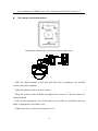
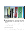
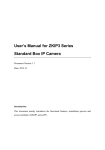
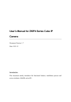
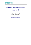
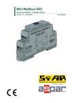
User’s Manual for ZKMD3 Series IR Vandal-proof Dome IP Camera Document Version: 1.7 Date: 2012.10 Introduction This document mainly introduces the functional features, installation process and access methods of ZKMD3 series IPC. . Important Notices Thanks for selecting our company’s IPC. Before use, please read through the user’s guide to avoid any unnecessary damage! All functions depend on the actual product. Since the product is subject to updating, our company is not responsible for any difference from this guide and not liable for any dispute over different technical parameters from this guide. The project is subject to any change without notice. To learn more, please visit our company’s website www.zkivision.com or local office. Table of Contents Table of Contents 1 Overview ............................................................................................................... 1 1.1 Product Description ..................................................................................... 1 1.2 Product Features .......................................................................................... 1 1.3 Technical Parameters ................................................................................... 3 1.4 Product Appearance ..................................................................................... 5 1.5 Connecting Terminals .................................................................................. 7 1.6 Basic Procedure .......................................................................................... 11 2 Installation and Network Configuration ...........................................................12 2.1 Hardware Installation..................................................................................12 2.2 Operating Environment ..............................................................................17 2.3 Network Connection ...................................................................................17 3 Accessing device ...................................................................................................19 3.1 Using Browser ............................................................................................19 3.2 Using RTSP Media Player ..........................................................................20 3.3 Using Mobile Devices ................................................................................22 3.4 Using Video Surveillance Software ............................................................25 I Overview 1 Overview 1.1 Product Description The ZKMD3 series products are day/night vandal-proof color IP cameras, which feature the aluminum alloy die casting design and IP66 protection grade. The series products are equipped with 2-megapixel CMOS sensors or high-quality CCD sensors made by Sony, which feature the long-distance infrared lamp projection, wide projection angle and night vision capability. The optimized H.264 coding algorithm guarantees the transmission of sharp and smooth video effect. The embedded Web Server enables users to conveniently implement real time surveillance and remote control for front end cameras via browser. The series products are either megapixel (high definition) or common pixel (standard definition) cameras, which can be wall mounted or ceiling mounted, easily installed and operated, and used in indoor or outdoor places. The products are applicable for the places requiring short distance and wide angle, tight security and all-weather surveillance, such as residence communities, factories and banks, as well as the occasions requiring remote network video. 1.2 Product Features Hi3512 high-performance multimedia processor, supporting H.264 Main Profile video coding Dual code stream, suitable for various networks Support all kinds of protocols, such as, TCP/IP, HTTP, TCP, UDP, ARP, SMTP, FTP, DHCP, DNS, DDNS, NTP and UPNP, etc. Aluminum alloy die casting design, IP66 protection grade, and best dustproof, waterproof, anti-corrosion and anti-riot effect Either wall mounted or ceiling mounted, and wide scope of uses Snap-on base to simplify the installation 1 User’s Manual for ZKMD3 Series IR Vandal-proof Dome IP Camera V1.7 Safe and reliable socket head lock screws Double-glass front cover for better optical isolation and mist prevention surface for better night viewing Three-layer shield +magnetic ring design to eliminate signal interference Numerous additional functions, e.g. alarm, audio talkback, 485 control, TF card and reset, etc. Support Ethernet power supply (PoE 802.3af regulation) (optional) Support WIFI (802.11b/g/n standard) wireless network module (optional) IR-Cut filters to automatically switch between day and night for optimal monitoring Double web indicator lamps for easy judgment of web status 4~9mm focus-adjustable lens, adjusted according to different environment Analog video output interface (for HD) to facilitate site commissioning Self-recovery from abnormality and auto reconnection after network interruption Automatically capture images during an alarm and send them to the designated email Support motion detection and external detector alarm Allow setting several alarm times and support the remote alarm linkage Support dynamic IP (DHCP) and dynamic domain name system (DDNS) Network time synchronization (NTP) HD cam to support the browsing by 14 users simultaneously, 4 in primary code stream and 10 in secondary code stream SD cam to support the browsing by 20 users simultaneously, 10 in primary code stream and 10 in secondary code stream 2 Overview 1.3 Technical Parameters Product Name Product Model Anti-Riot Infrared Semi-Spherical IP Camera ZKMD372 ZKMD352 1/3" megapixel progressive 1/3.2" two-megapixel CMOS sensor progressive CMOS sensor WDR HD HD Cam Properties Image Sensor Image Resolution 1280×720 Day/Night Switch IR-Cut filter switch Type of Lens 4~9mm manual aperture lens Minimum Brightness 1 Lux (IR lamp off), 0 Lux (IR lamp on) 25 built-in Φ5 infrared lamps, 10~15m effective projection distance, IR Lamp 60 degrees projection angle Video Coding Primary Processor Hi3512 Operating System Embedded Linux Video Compression H.264 main profile level 3 Algorithm Audio Compression G.726/G.711 Algorithm Video Compression Code 32~6114 Kbits/s adjustable Rate Primary Code Stream 1280x720 Video Resolution Secondary Code Stream 320x240 Video Frame Rate 1~25 frames optional Brightness, Saturation, Contrast, Illumination, Sensitivity, Shutter, Video WDR HD Image Up/Down, Image Left/Right, Night Vision Mode, Wide Dynamic Mode adjustable Parameters HD Brightness, Saturation, Contrast, Image Up/Down, Image Left/Right 3 User’s Manual for ZKMD3 Series IR Vandal-proof Dome IP Camera V1.7 adjustable Functional Interfaces Audio Interface Alarm Input 1 Mic input and 1 linear output (optional) 1 alarm input (normally opened or normally closed) (optional) 1 switch output, maximum working voltage: AC 120V/1A, DC Alarm Output 24V/1A Motion Detection Allow 4 independent detection areas Control Interface 1 RS485 Support TF card for video storage and image capture, 32G maximum Memory (optimal) 10Base-T/100Base-TX Ethernet interface Network Interface WiFi 802.11b/g wireless (optional) Supported Network TCP/IP, HTTP, TCP, ICMP, UDP, ARP, IGMP, SMTP, FTP, DHCP, Protocols DNS, DDNS, NTP, UPNP and RTSP, etc. Working Environment DC 12V, ≥1.5A Input Power POE Ethernet power supply: comply with 802.3af regulation (optional) Maximum Power 8W Consumption Working Temperature -20~+55 °C Working Humidity 10%~95%RH Level of Protection IP66 Installation Mode Wall-mounted 4 Overview 1.4 Product Appearance Diagram of ceiling mounted mode fixing base camera transparent cover Diagram of wall mounted mode wall mounted bracket fixing base camera transparent cover Dimensional drawing of ceiling mounted mode (in mm) Right View Dimensional drawing of wall mounted mode (in mm) 5 User’s Manual for ZKMD3 Series IR Vandal-proof Dome IP Camera V1.7 Right View Front view 6 Overview 1.5 Connecting Terminals (8) (7) (6) (5) (4) (3) (2) (1) 1. Power Interface: Connect to the adapter. This IPC employs the power supply of DC 12V and no lower than 1.5A. Do not use any different power supply as it may damage the camera. 2. Network Interface: 10/100M self-adapting Ethernet interface is used to connect the camera with various network equipments, such as, switch, router and hub. When it is connected to 10M network, the orange lamp is also on. When it is connected to 100M network, the green lamp is always on. This interface can also employ Ethernet power supply (POE, optional) and allow the transmission of power and data through Ethernet cable. P oE S w icth 3. Reset Button: When the camera fails to function during incorrect operation or accidental failure (e.g. forget IP address or password), or it is used in different scenes, press down the button for above 5s after a delay of 30s from powering on to restore the camera to its factory default. The default user’s name is “admin”, the default password is “admin” and the default IP address is “192.168.1.88”. 7 User’s Manual for ZKMD3 Series IR Vandal-proof Dome IP Camera V1.7 4. Alarm Interface: Connect to alarm input and alarm output. When the camera receives an alarm from alarm output or Web motion detection, this interface can send a signal to alarm output to realize real-time monitoring and overall protection while triggering a remote alarm. The specific interfaces are presented in the following figure. 12345 1) NC COM NO GND IN Alarm output Alarm input The schematic diagram of alarm input connection is as follows: Alarm Input Terminals (IN,GND) switch Alarm Input Device Power Supply of Alarm Input Device Schematic Diagram of Alarm Input (Normally Opened) Connection Alarm Input Terminals (IN,GND) switch Alarm Input Device Power Supply of Alarm Input Device Schematic Diagram of Alarm Input (Normally Closed) Connection 8 Overview Notice: When external alarm input is started, different alarm inputs have different software settings. Please select “Normally Opened” or “Normally Closed” on the Web page according to the type of alarm input, as detailed in User Manual – Using Browser for Video Surveillance. 2) The schematic diagram of alarm output default connection is as follows: Alarm Output Terminals (COM,NO) Alarm switch Output Device Power Supply of Alarm Output Device Schematic Diagram of Alarm Output (Normally Opened) Connection Note: The connection with normally opened alarm output (e.g. normally opened lock) is performed as shown in the following schematic diagram. Alarm Output Terminals (COM,NO) Alarm switch Output Device Power Supply of Alarm Output Device Schematic Diagram of Alarm Output (Normally Closed) Connection 5. RS485 Interface: Supports standard 485 PTZ protocols, for remote device control. The camera can be turned remotely and monitored in all directions. 9 User’s Manual for ZKMD3 Series IR Vandal-proof Dome IP Camera V1.7 The relevant parameters are set as detailed in User Manual – Using Browser for Video Surveillance. The specific interface is shown in following figure. 123 6. 485+ 485GND Audio Input Interface: Connect to external audio acquisition (e.g. MIC) for sound acquisition as detailed in User Manual – Using Browser for Video Surveillance. 7. Audio Output Interface: Connect to audio player (e.g. active speaker) for sound broadcasting. 8. Analog Video Output Interface: Special for SD camera and engineering commissioning. After being installed and connected, this interface can be used locally to connect with the image display device and adjust the camera angle to the appropriate monitoring area according to the scene in the video. 10 Overview 1.6 Basic Procedure 1. Unpack and check whether any component is missing; 2. Connect the camera to computer by means of patch cable; 3. If your computer IP is in a network section different from camera IP, please set it to the same network section as camera IP, such as, 192.168.1.87. 4. Log in the camera through client software or browser to check whether the video functions normally; 5. Adjust the code stream and other video parameters; 6. Modify the network parameters of camera and reboot the device; 7. Repeat Step 3; 8. Revisit the camera through client software or browser to check till the video functions normally; 9. Install the camera and adjust the camera angle to the appropriate area; 10. Visit the camera through client software or browse for video monitoring. 11 User’s Manual for ZKMD3 Series IR Vandal-proof Dome IP Camera V1.7 2 Installation and Network Configuration 2.1 Hardware Installation Installation Notices: 1. Read through the guide for installation prior to installation. 2. Check whether any component is missing against the packing list, if yes, please contact your supplier. 3. Wire during power off. If the camera does not function normally during operation, please cut off the power before check. Do not connect cables when power is on! Notice: The wiring during power on may seriously damage the camera, which will be disqualified from the guarantee. DC12V/1.5A 4. Use the power supply of DC12V and no lower than 1.5A for the camera or PoE power supply (optional). Too high or low voltage, or AC power supply may cause the abnormal operation of the camera. 12 Installation and Network Configuration 5. Use the standard power cord when the power supply is too far away from the camera, and consider the voltage drop caused by long distance. 6. Read through the instructions for connecting terminal and wire strictly according to interfaces. Any damage to the camera due to improper operation will be disqualified from the guarantee. 7. All the exposed parts of connecting terminal should not exceed 5mm, in order to prevent any accidental contact from damaging the camera. Uncovered cable should be less than 5mm 123 8. Mount the relay equipment in the middle to avoid signal attenuation when the straight communication distance from the camera to the incoming equipment exceeds 80m. Please use repeater when exceeding 80m 9. When RS485 is employed, if the communication distance exceeds 100m, the final equipment on the 485 bus must be connected to a 120Ω terminal resistance in parallel. 10. Pay attention to provide lightning protection if the camera is mounted outdoor. Do not touch the camera during lightning. 13 User’s Manual for ZKMD3 Series IR Vandal-proof Dome IP Camera V1.7 11. Use the camera in the working conditions: Ambient temperature: -20 ℃ ~ +55 ℃; ambient relative humidity: 10% ~ 95%RH. 12. Please keep the lens and transparent cover clean. If the transparent cover is dirty, please wipe it with clean soft cloth. 14 Installation and Network Configuration Ceiling mount installation method: wiring hole positioning hole Installation template for ceiling mounted mode (unit: mm) ③ ② ④ ①Affix the paper template to the ceiling and drill holes according to the marked circles in the paper template. ②Affix the camera and pedestal to the ceiling by 4 screws. ③Adjust the lens angle to appropriate surveillance area. ④Tighten the screws to fix the transparent cover. 15 User’s Manual for ZKMD3 Series IR Vandal-proof Dome IP Camera V1.7 Wall mount installation method: wiring hole positioning hole Installation template for wall mount method (unit: mm) ③ ② ④ ⑤ ①Affix the paper template to the wall and drill holes according to the marked circles in the paper template. ②Affix the pedestal to the wall by 4 screws. ③Hang the camera in the pedestal and tighten the 4 screws, to fix the camera in related pedestal.. ④Take off the transparent cover from camera by screwdriver, and adjust the lens angle to appropriate surveillance area. ⑤Tighten the screws to fix the transparent cover. 16 Installation and Network Configuration 2.2 Operating Environment Operating System: Windows 98/ Windows2000, 2003, XP, Vista/ Windows 7; CPU: Pentium III 1GHZ or higher; Memory: 256MB or higher, at least 128MB (possibly affect performance and some functions); HDD: 1.5GB available; Screen Resolution: 800×600 or higher; Browser: IE6.0 or latest version; A better computer can considerably improve the effect of monitoring, so it is recommended to use a better computer for monitoring. 2.3 Network Connection The device can be connected to network in two ways. The first way is to connect to the network by means of Ethernet cable, and the second way is to connect to wireless network (optional). .............................. Connect by Ethernet Cable (1) Use Ethernet cables to connect the device to network or directly to computer. (2) Connect the power supply of the device. (3) During normal connection, if it is a 10M network, the orange lamp is always on; if it is a 100M network, the green lamp is also on. The physical connection with network is completed after the lamp shining. (4) In the “Start” menu, select “Programs”--“Accessories”--“Command Prompt”, and input the ping command to the device address (e.g.: type in “ping 192.168.1.88”). If “Request timed out” does not pop up, the device is successfully connected to network. 17 User’s Manual for ZKMD3 Series IR Vandal-proof Dome IP Camera V1.7 Notice: 1) The default IP address is “192.168.1.88” and the default HTTP port is 80. If needed to change IP address or port, refer to Network Setting in User Manual – Using Browser for Video Surveillance. 2) If the device is in a network section different from computer, refer to How to Visit IPC on Internet in User Manual – Using Browser for Video Surveillance for the connection during different network sections. .............................. Connect to Wireless Network Before starting the wireless network, connect the IPC to network by Ethernet cable, visit the device through browser, enter “Network Setting” interface, and set the wireless network connection following the operating procedure, as detailed in Network Setting in User Manual – Using Browser for Video Surveillance. 18 Accessing device 3 Accessing device There are 4 methods can be used to access the device: Browser, RTSP Media Player, Mobile Device and Video Surveillance Software (ZKiVision client software). 3.1 Using Browser 1. Open a browser, type in the dynamic domain name or IP address of the device (e.g. http://192.168.80.123), press "Enter" to open the following login interface: 2. Type in user’s name and password, and click “OK” and the guide page will show as below: 3. Click Watch the video to enter Preview interface: 19 User’s Manual for ZKMD3 Series IR Vandal-proof Dome IP Camera V1.7 Note: When accessing the device via browser for the first time, it is necessary to download the control. More details about how to use browser for video surveillance, please refer to User Manual – Using Browser for Video Surveillance in the supplied CD. 3.2 Using RTSP Media Player 1. Download and install a media player supporting RTSP protocol, e.g. VLC media player. 2. Open the media player, select the menu “Media”—“Open Network Stream”, pop up the input interface of URL. 20 Accessing device 3. Type in the network URL in the form of rtsp://<IP address>:<RTSP port>/<stream code>. 21 User’s Manual for ZKMD3 Series IR Vandal-proof Dome IP Camera V1.7 4. Click “Play” and the media player will play the real-time video of the device. Note: 1) The default RTSP port of device is 554. If it must be modified, please refer to User Manual – Using Browser for Video Surveillance in the supplied CD. 2) If it is necessary to learn about how to use RTSP media player for video surveillance, please refer to User Manual – Using Browser for Video Surveillance in the supplied CD. 3.3 Using Mobile Devices If it is necessary to use mobile devices for video surveillance, please firstly ensure the device can be accessed on Internet. Please refer to User Manual – Using Browser for Video Surveillance in the supplied CD for more details about how to visit device on Internet. 22 Accessing device 1. Install the media player in the supplied CD into the mobile device. 2. Click the icon “HIPlayer” to enter the media player. 23 User’s Manual for ZKMD3 Series IR Vandal-proof Dome IP Camera V1.7 3. Click the button at the lower right corner to the setting interface, type in the user name, password, domain name and port of the device, or select a set device from the favorite. 4. Click “Play” and the medial player will play the real-time video of the device. Note: 1) The operating system of mobile device must be Android, BlackBerry or iOS . 2) As the internet service is required for watching video, please consult with your internet service provider for specific charges. 24 Accessing device 3.4 Using Video Surveillance Software ZKiVision Client Software is our company's free video surveillance software, which can help manage and monitor multiple devices in a real-time manner. Install the software in the supplied CD, and add devices to the software. Then the real-time monitoring can be started. If needed to learn about how to use the video surveillance software, refer to ZKiVision Client Software User Manual in the CD. 25