1
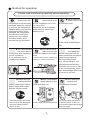
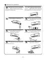
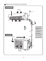
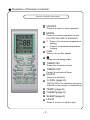
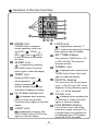
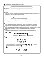
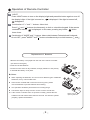
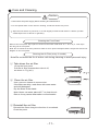
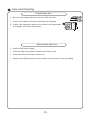
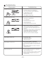
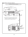
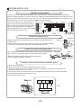
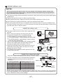
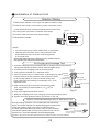
Models
B2VI-09/B2VO-09
B2VI-12/B2VO-12
Wall Mounted Unit
Owner’s Manual
Thank you for choosing INVENTOR air
conditioning system. For correct use of this unit,
please read this manual carefully and keep it for
future reference.
66129912898
CONTENTS
Operation and maintenance
■ Notices for operation ............................................................1
■ Notices for use ................................................................... 3
■ Names and functions of each part .......................................... 4
■ Operation of Remote Controller ............................................. 5
■ Emergency operation ......................................................... 10
■ Care and Cleaning .............................................................11
■ Troubleshooting ................................................................ 13
Installation service
■
■
■
■
Notices for Installation ........................................................ 16
Installation Drawing ........................................................... 19
Installation of Indoor Unit .................................................... 20
Installation of Outdoor Unit .................................................. 22
■ Check after Installation and Operation Test ............................ 23
■ Installation and Maintenance of Healthy Filter(Optional) ............ 24
■ Configuration of connection pipe and additional volume of refrigerant ........... 25
The figures in this manual may be different with the material objects, please refer
to the material objects for reference.
This symbol stands for the items
should be forbidden
This symbol stands for the items
should be followed
Do not dispose this product as unsorted municipal waste.
Collection of such waste separately for special treatment
is necessary.
Notices for operation
Please read the following carefully before operating
★ When the voltage
is very high, the
components would be easily
damaged, when the voltage
is very low, the compressor
vibrates terribly and that the
refrigerant system will be
damaged, the compressor
and electric components
cannot work, the voltage
should be stable; there
shouldn’t be big fluctuation.
★ Don’ t leave windows
and doors open for
a long time while operating
the air conditioner.
It can decrease the air
conditioning capacity.
★ When having a
burning smell or
smoke, please turn off the
power supply and contact
with the service center.
If the abnormity still exists,
the unit may be damaged,
and may cause electric
shock or fire.
★ Be sure to pull out
the power plug as
the air conditioner not in use
for a long time.
Otherwise, the accumulated
dusts that may cause over
heating or fire.
Never splice the
power cord or use
an extended cord.
It can cause overheating or
fire.
★ Don't block the air
★ The power supply
must adopt the
intake or outlet vents
of both the outdoor and indoor special circuit that with air
units.
switch protection and assure
It can decrease the air conditioning it has enough capacity.
capacity or cause a malfunction.
The unit will be turned
on or off according to your
requirement automatically,
please do not turn on or turn
off the unit frequently, otherwise disadvantage effect may
be caused to the unit.
★Keep combustilble
spray away from the
units more than 1m.
★ Don’t attempt to
repair the air
conditioner by yourself.
The wrong repair will lead to
It can cause a fire or explosion an electric shock or fire, so
you should contact the service
center to repair.
1
Notices for operation
★ Please don't cut off or damage the
power cords and control cords.
If they are damaged, please ask the qualified
personnel to change them.
★ To adjust the airflow direction
appropriately. When operating
the unit, to adjust the vertical and lateral air
flow direction by use of remote controller.
Swing louver
★ Don’t insert your hands or stick into
the air intake or outlet vents.
Guide louver
★
Don’t blow the wind to animals
and plants directly. It can cause
a bad influence to them.
★ Don’t use the air conditioner
★ Don’t apply the cold wind to
the body for a long time.
It can cause the health problems.
for other purposes, such as
drying clothes, preserving foods, etc.
★ Splashing water on the air
★ Don’t place a space heater
conditioner can cause an electric
shock and malfunction.
2
near the air conditioner.
Notices for use
Working principle and special functions for cooling
Principle:
Air conditioner absorbs heat in the room and transmit to outdoor and discharged, so that
indoor ambient temperature decreased, its cooling capacity will increase or decrease by
outdoor ambient temperature.
Anti-freezing function:
If the unit is running in COOL mode and in low temperature, there will be frost formed on
the heat exchanger, when indoor heat exchanger temperature decreased below 0℃ , the
indoor unit microcomputer will stop compressor running and protect the unit.
Working principle and special functions for heating
Principle:
* Air conditioner absorbs heat from outdoor and transmits to indoor, in this way to increase
room temperature. This is the heat pump heating principle, its heating capacity will be
reduced due to outdoor temperature decrease.
* If outdoor temperature becomes very low, please operate with other heating equipments.
Defrosting:
* When outdoor temperature is low but high humidity, after a long while running, frost will
form on outdoor unit, that will effect the heating effect, at this time, the auto defrosting
function will act, the heat running will stop for 8-10mins.
* During the auto defrosting, the fan motors of indoor unit and outdoor unit will stop.
* During the defrosting, the indoor indicator flashes, the outdoor unit may emit vapor.
This is due to the defrosting, it isn't malfunction.
* After defrosting finished,the heating will recover automatically.
Anti-cool wind function:
In "Heat" mode, under the following three kinds of state, if indoor heat exchanger doesn't
arrive at certain temp., indoor fan will not act, in order to prevent cool wind blowing(within
2 mins):
1. Heating starts. 2.After Auto Defrost finished. 3.Heating under the low temperature.
Working temperature range
Indoor sideDB/WB(oC)
Outdoor sideDB/WB(oC)
Maximum cooling
32/23
43/26
Minimum cooling
21/15
21/
Maximum heating
27/---
24/18
Minimum heating
20/---
-5/-6
The operating temperature range (outdoor temperature) for cooling unit is -7℃~ 43℃;
for cooling and heating unit is -7~43℃.
3
Names and functions of each part
Indoor unit
Air in
⑵
⑴
⑶
⑷
Air out
⑹
⑸
⑴ Power cable
⑼
⑵ Front panel
⑶ Filter
⑷ Guide louver
⑸ Wall pipe
⑹ Bind tape
Outdoor unit
⑺ Connection wire
⑻ Drainage pipe
Air in
⑼ Remote control
⑺
⑻
Air out
4
Operation of Remote Controller
Remote Controller Description
ON/OFF
1
Press it to start or stop operation
MODE
2
Press it to select operation mode
(AUTO/COOL/DRY/FAN/HEAT)
+ : Press it to increase temperature
3
setting
- : Press it to decrease temperature
setting
4
FAN
5
2
1
12
11
13
TIMER ON
Press it to set auto-on timer
7
9
Press it to set swing angle
7
6
5
10
6
3
4
Press it to set fan speed
8
TIMER OFF
8
Press it to set auto-off timer
CLOCK
9
Press it to set clock
14
10
X-FAN (page 8)
(NOTE:X-FAN is the alternative expression
of BLOW for the purpose of understanding.)
12
TEMP (page 8)
TURBO(page 8)
13
SLEEP(page 8)
14
LIGHT
11
Press it to turn on/off the light.
5
Operation of Remote Controller
25
24
23
15
22
21
16
17 18 19
15
16
MODE icon:
20
If MODE button is pressed,
current operation mode icon
(AUTO),
( COOL),
(DRY),
(FAN) or (HEAT
is only for heat pump models)
will show.
21
or OFF will blink.This area will
show the set time.
SLEEP icon :
22
TURBO icon:
is displayed when pressing the
TURBO button.Press this button
again to clear the display.
TEMP icon:
23
DIGITAL display:
This area will show the set temperature. In SAVE mode,"SE" will be
displayed. During defrosting operation, “H1” will be displayed.
Up & down swing icon:
24
is displayed when pressing
the up & down swing button.
Press this button again to clear the
display.
25
19
SET TIME display:
After pressing TIMER button, ON
Pressing TEMP button,
(indoor
(set temperature),
ambient temperature)
(outdoor ambient temperature)
and blank is displayed circularly.
18
LOCK icon:
is displayed by pressing "+"
and “-” buttons simultaneously.Press
them again to clear the display.
is displayed by pressing
the SLEEP button. Press this
button again to clear the display.
17
20
LIGHT icon:
is displayed by pressing the
LIGHT button.Press LIGHT button
again to clear the display.
X-FAN icon:
is displayed when pressing the
X-FAN button. Press this button
again to clear the display.
FAN SPEED display:
Press FAN button to select the
desired fan speed setting(AUTO-
Low-Med-High).Your selection will
be displayed in the LCD windows,
except the AUTO fan speed.
6
Operation of Remote Controller
Remote Controller Description
1 ON/OFF :
Press this button to turn on the unit. Press this button again to turn off the unit.
2 MODE :
Each time you press this button,a mode is selected in a sequence that goes from AUTO,
COOL,DRY, FAN, and HEAT *, as the following:
FAN
HEAT *
COOL
AUTO
DRY
*Note: Only for models with heating function.
After energization, AUTO mode is defaulted. In AUTO mode, the set temperature will not
be displayed on the LCD, and the unit will automatically select the suitable operation
mode in accordance with the room temperature to make indoor room comfortable.
3
+:
Press this button to increase set temperature. Hold it down for above 2 seconds to
rapidly increase set temperature. In AUTO mode, set temperature is not adjustable.
4
Press this button to decrease set temperature.
Hold it down for above 2 seconds to rapidly
.
decrease set temperature. In AUTO mode, set temperature is not adjustable.
5 FAN :
This button is used for setting fan speed in the sequence that goes from AUTO,
, to
, then back to Auto.
Auto
Low speed
6
Medium speed
High speed
:
Press this button to set up & down swing angle, which circularly changes as below:
OFF
This remote controller is universal. If any command
the unit will carry out the command as
indicates the guide louver swings as:
7
,
or
is sent out,
,
Operation of Remote Controller
7 TIMER ON:
Press this button to initiate the auto-ON timer. To cancel the auto-timer program, simply
press this button again.
After pressing this button,
disappears and "ON "blinks. 00:00 is displayed for ON time
setting. Within 5 seconds, press + or - button to adjust the time value. Every press of either
button changes the time setting by 1 minute. Holding down either button rapidly changes the
time setting by 1 minute and then 10 minutes. Within 5 seconds after setting, press TIMER
ON button to confirm.
8 TIMER OFF :
Press this button to initiate the auto-off timer. To cancel the auto-timer program, simply
press the button again.TIMER OFF setting is the same as TIMER ON.
9 CLOCK :
Pressing CLOCK button,
blinks. Within 5 seconds, pressing + or - button adjusts the
present time. Holding down either button above 2 seconds increases or decreases the
time by 1 minute every 0.5 second and then by 10 minutes every 0.5 second. During
blinking after setting, press CLOCK button again to confirm the setting, and then
will be constantly displayed.
10 X-FAN:
P ressing X-FAN button in COOL or DRY mode,the icon
is displayed and the indoor
fan will continue operation for 10 minutes in order to dry the indoor unit even though you
have turned off the unit.
After energization, X-FAN OFF is defaulted. X-FAN is not available in AUTO, FAN or
HEAT mode.
11 TEMP:
Press this button, could select displaying the indoor setting temperature or indoor ambient
temperature.When the indoor unit firstly power on it will display the setting temperature,
if the temperature's displaying status is changed from other status to" ",displays the
ambient temperature, 5s later or within 5s, it receives other remote control signal that will
return to display the setting temperature. if the users haven't set up the temperature
displaying status,that will display the setting temperature.
12 TURBO:
Press this button to activate / deactivate the Turbo function which enables the unit to
reach the preset temperature in the shortest time. In COOL mode, the unit will blow strong
cooling air at super high fan speed. In HEAT mode, the unit will blow strong heating air
at super high fan speed. (This function is not applicable for some models).
13 SLEEP :
Press this button to go into the SLEEP operation mode. Press it again to cancel this
function. This function is available in COOL, HEAT (Only for models with heating
function) or DRY mode to maintain the most comfortable temperature for you.
8
Operation of Remote Controller
14
LIGHT:
Press LIGHT button to turn on the display's light and press this button again to turn off
the display's light. If the light is turned on ,
is displayed. If the light is tunrned off,
disappears.
15 Combination of "+" and "-" buttons: About lock
Press "+ " and "-" buttons simultaneously to lock or unlock the keypad. If the remote
controller is locked,
is displayed. In this case, pressing any button,
blinks
three times.
16 Combination of "MODE" and "-" buttons: About switch between Fahrenheit and Centigrade
At unit OFF, press "MODE " and "- " buttons simultaneously to switch between ℃ and℉.
Replacement of Batteries
1.Remove the battery cover plate from the rear of the remote controller.
(As shown in the figure)
2.Take out the old batteries.
3.Insert two new AAA1.5V dry batteries, and pay attention to the polarity.
4. Reinstall the battery cover plate.
★ Notes:
●
When replacing the batteries, do not use old or different types of batteries.
●
If the remote controller will not be used for a long time, please
Otherwise, it may cause malfunction.
remove batteries to prevent batteries from leaking.
●
The operation should be performed in its receiving range.
●
●
It should be kept 1m away from the TV set or stereo sound sets.
If the remote controller does not operate normally, please take the
batteries out and reinsert them after 30 seconds. If it still can't operate
properly, replace the batteries.
9
Sketch map for
replacing batteries
Emergency Operation
Emergency Operation
When the wireless remote control is lost or damaged, please use the manual switch, at this
time, it is running in Auto Run mode that will not change the temperature setting value and
fan speed.
The manual switch can be operated as follow:
●
●
At operation: When the unit stopped running,
press ON/OFF button, unit will enter into AUTO
RUN mode. The microcomputer will accord to
the room temperature to select the (COOL,
HEAT, FAN) mode automatically, to obtain the
comfortable effect.
AUTO/STOP
Manual Switch
At stopping: When the unit is running, press the
ON/OFF button of the manual switch, the unit
will stop work.
The code switch can be operated as follow:
●
●
At operation: When the unit is stopped running,
adjust the code switch to AUTO, the unit will
enter into AUTO RUN mode. The microcomputer
will accord to the room temperature to select the
(COOL, HEAT, FAN) mode automatically, to
obtain the comfortable effect.
At stopping: When the unit is running, adjusts
the code switch to STOP position, the unit will
stop work.
10
Code Switch
(only for some models)
Care and Cleaning
Caution
● Disconnect the power supply before cleaning and maintenance.
●? Do not splash water on the units for cleaning, as electric shocks may occur.
●? Wipe the units with a dry soft cloth, or a cloth slightly moistened with water or cleaner (not with
volatile liquid such as thinner or gasoline).
Cleaning the Front Panel
Remove the front panel. Dip a piece of cloth into the water colder than 45 ℃ and dry it . Then wipe
the dirty part of front panel.
Note: Do not immerse the front panel into water so as to protect microprocessor components and circuit
diagram on the front panel.
Cleaning the Air Filter (every 3 months)
Note:Do not touch the fin of indoor unit during cleaning to avoid personal injury.
① Take down the air filter
Lift up the front panel.
Pull the air filter downwards to take it off,
as shown in Fig.(a, b).
② Clean the air filter
Use a vacuum cleaner to remove dust.
If the filters are dirty, wash them with warm water
and mild detergent.
Dry the filters in the shade.
Note: Never use water above 45 ℃ to clean the air
filter as it may cause deformation or discoloration.
③ Reinstall the air filter
Reinstall the filters along the direction of arrowhead.
Close the panel.
11
(
a)
(
b)
Care and Cleaning
Check before Use
①
Be sure that nothing obstructs the air outlet and inlet.
② Check if the batteries of remote controller are replaced.
③ Check if the installation stand of the outdoor unit is damaged.
If damaged, consult the technicians.
Maintenance after Use
①
Switch off the power supply.
②
Clean the filters and bodies of indoor and outdoor units.
③
Clear obstructions from the outdoor unit.
④ Repaint the rubiginous place on the outdoor unit to prevent it from spreading.
12
Troubleshooting
CAUTION
The air conditioner is not expected to be serviced by users. Incorrect repair may cause
electric shock or fire, so please contact an authorized service center for professional
service. The following checks prior to contact may save your time and money.
Phenomenon
Troubleshooting
The unit does not operate:
The unit does not operate if it is turned on
immediately after being turned off. This is to
protect the unit. You are expected to wait
for about 3 minutes.
●
Waiting
Odours are emitted:
"Water flowing" noise:
Mist is emitted in COOL mode
Cracking noise:
●
Some odours may be emitted from the indoor
unit. This is the result of room smells (such as
furniture, tobacco, ect.) which have been taken
into the air conditioner.
●
Consult authorized service center for cleaning
if the odours still exist.
●
The swishing noise like water flowing is the
sound of refrigerant flowing inside the unit.
●
During cooling operation, a thin mist may be
seen emitted from the indoor unit due to high
room temperature and humidity.
After a period of time,the mist will disappear
with the decrease of room temperature and
humidity.
●
This is the sound of friction caused by expansion
and/or contraction of panel or other parts due
to the change of temperature.
13
Troubleshooting
Phenomenon
The unit can not be started up:
Troubleshooting
● Is the power cut off?
●
Is the power plug loose? (If applicable )
●
Is the circuit protection device tripped off?
● Is voltage higher or lower?
(Tested by professionals)
Breaking off
Cooling/Heating effect is poor:
Remote controller is not available:
Water leakage of indoor unit :
● Is the TIMER correctly used?
●
Is temperature setting appropriate?
●
Is the inlet or outlet blocked?
●
Is the filter dirty?
●
Is the window or the door open?
●
Is low fan speed set?
●
Are there heat sources in the room?
●
Check if there is magnetic or electrical interference
near the unit that may affecting operation of
the controller. In this case, pull the plug out and
reinsert it.
●
Is the remote controller within its operating range
or obstructed? Check the condition of the
batteries and replace them if necessary.
●
Check if the remote controller is damaged.
● The humidity is high.
Condensate overflows.
Drain hose is loose.
●
●
Water leakage of outdoor unit :
● During cooling operation, condensate is
generated around the pipes and connection joints.
● During defrosting operation, the thaw water flows
out.
● During heating operation, the water on the heat
exchanger drips out.
Noise from indoor unit .
● The noise emitted when the fan or compressor
relay is switching on or off.
● When the defrosting operation is started or stopped,
there is a sound of refrigerant flowing in the
reverse direction.
14
Troubleshooting
Phenomenon
Troubleshooting
Indoor unit can not blow air:
● In HEAT mode, when the temperature of indoor
heat exchanger is very low, air flow is stopped
in order to prevent cold air. (Within 2minutes)
●
In HEAT mode, when the outdoor temperature
is low or humidity is high, frost will be formed on
the outdoor heat exchanger. The unit will defrost
automatically and indoor unit will stop blowing
air for 3-12minutes.
●
During defrosting operation, water or vapour may
be emitted.
● In DRY mode, the indoor fan will stop blowing air
for 3-12 minutes in order to avoid condensate
being vaporised again.
●
If the unit operates at high humidity for a
long time, moisture will be generated on
the air outlet grill and then drip off.
C5: Malfunction of connector jumper:
●
Check if the connector jumper contacts
properly. If the PCB is to be replaced,
please take off the old for the new PCB.
F1: Malfunction of indoor ambient temperature
sensor
●
Check if indoor room temperature sensor is
connected properly
F2: Malfunction of evaporator temperature
sensor
●
Check if the evaporator temperature is
connected properly.
H1: Defrosting
●
It is normal.
Moisture on air outlet :
If any one of the following situations occurs, immediately stop all operations,
cut off the power supply, and contact the authorized personnel
There is harsh sound during operation.
Strong odours are emitted during operation.
Water is leaking from the unit.
The air switch or protection switch often trips.
Water or other liquid is splashed into the unit.
Power cord and power plug is overheating.
15
Stop operation
and cut off the power supply.
Notices for Installation
Caution
1. The unit should be installed only by authorized service center according to local or
government regulations and in compliance with this manual.
2. Before installing, please contact with local authorized maintenance center. If the unit is
not installed by the authorized service center, the malfunction may not be solved
due to incovenient contact between the user and the service personnel.
3. When removing the unit to the other place, please firstly contact with the local authorized
service center.
4 . Warning: Before obtaining access to terminals, all supply circuits must be disconnected.
5. If the supply cord is damaged, it must be replaced by the manufacturer, its service agent
or similarly qualified persons in order to avoid a hazard.
6. The appliance must be positioned so that the plug is accessible.
7. The temperature of refrigerant line will be high; please keep the interconnection cable
away from the copper tube.
8. This appliance is not intended for use by persons (including children) with reduced physical,
sensory or mental capabilities, or lack of experience and knowledge, unless they have been
given supervision or instruction concerning use of the appliance by a person responsible
for their safety.
Children should be supervised to ensure that they do not play with the appliance.
Installation Site Instructions
Proper installation site is vital for correct and efficient operation of the unit. Avoid the
following sites where:
●
●
●
●
●
●
Strong heat sources, vapours, flammable gas or volatile liquids are emitted.
High-frequency electro-magnetic waves are generated by radio equipment,
welders and medical equipment.
Salt-laden air prevails (such as close to coastal areas).
The air is contaminated with industrial vapours and oils.
The air contains sulphures gas such as in hot spring zones.
Corrosion or poor air quality exists.
16
Notices for Installation
Installation Site of Indoor Unit
1. The air inlet and outlet should be away from the obstructions. Ensure the air can be
blown through the whole room.
2. Select a site where the condensate can be easily drained out, and where it is
easily connected to outdoor unit.
3. Select a place where it is out of reach of children.
4. Select a place where the wall is strong enough to withstand the full weight and vibration
of the unit.
5. Be sure to leave enough space to allow access for routine maintenance. The installation
site should be 250cm or more above the floor.
6. Select a place about 1m or more away from TV set or any other electric appliance.
7. Select a place where the filter can be easily taken out.
8. Make sure that the indoor unit is installed in accordance with installation dimension
instructions.
9. Do not use the unit in the laundry or by swimming pool etc.
Installation Site of Outdoor Unit
1. Select a site where noise and outflow air emitted by the unit will not annoy neighbors.
2. Select a site where there is sufficient ventilation.
3. Select a site where there is no obstruction blocking the inlet and outlet.
4. The site should be able to withstand the full weight and vibration.
5. Select a dry place, but do not expose the unit to direct sunlight or strong wind.
6. Make sure that the outdoor unit is installed in accordance with the installation instructions,
and is convenient for maintenance and repair.
7. The height difference between indoor and outdoor units is within 5 m, and the length of
the connecting tubing does not exceed 10 m.
8. Select a place where it is out of reach of children.
9. Select a place where the unit does not have negative impact on pedestrians or on the city.
Safety Precautions for Electric Appliances
1. A dedicated power supply circuit should be used in accordance with local electrical
safety regulations.
2. Don't drag the power cord with excessive force.
3. The unit should be reliably earthed and connected to an exclusive earth device by the
professionals.
4. The air switch must have the functions of magnetic tripping and heat tripping to prevent
short circuit and overload.
5. The minimum distance between the unit and combustive surface is 1.5m.
6. The appliance shall be installed in accordance with national wiring regulations.
7. An all-pole disconnection switch with a contact separation of at least 3mm in all poles
should be connected in fixed wiring.
Note:
●
●
Make sure the live wire, neutral wire and earth wire in the family power socket are properly
connected. There should be reliable circuit in the diagram.
Inadequate or incorrect electrical connections may cause electric shock or fire.
17
Notices for Installation
Earthing Requirements
1. Air conditioner is type I electric appliance. Please ensure that the unit is reliably earthed.
2. The yellow-green wire in air conditioner is the earthing wire which can not be used
for other purposes. Improper earthing may cause electric shock.
3. The earth resistance should accord to the national criterion.
4. The power must have reliable earthing terminal. Please do not connect the earthing
wire with the following:
① Water pipe
②Gas pipe
③ Contamination pipe
④ Other place that professional personnel consider is unreliable
5. Including an air switch with suitable capacity, please note the following table. Air switch
should be included magnet buckle and heating buckle function, it can protect the
circuit-short and overload. (Caution: please do not use the fuse only for protect the circuit)
Air-conditioner (W)
Air switch capacity
09K、12K
10A
-18-
Installation dimension diagram
Installation dimension diagram
Space to the ceiling
Above
Space to the wall
Above
Above
Space to the wall
Above
Air outlet side
Space to the floor
The dimensions of the space necessary for correct
installation of the appliance including the minimum
permissible distances to adjacent structures
Space to the obstruction
Above
●
Above
Air inlet side
e
ov
Ab
Above
Space to the wall
Space to the wall
Above
ve
o
Ab
Air outlet side
540
19
286
Install indoor unit
Install the rear panel
1.Always mount the rear panel horizontally. Due to the water tray of indoor unit has been adopted the
both-way drainage design, the outlet of water tray should be adjusted slightly down when installing, that is
taking the outlet of the water tray as the center of a circle, the included angle between the evaporator and
level should be 0 or more, that is good for condensing water drainage.
Wall
2.Fix the rear panel on the wall with screws. Wall
Mark on the middle of it
Gradienter
Space
Space
(Where is pre-covered with plastic granula)
3.Be sure that the rear panel has been fixed
firmly enough to withstand the weight of an
adult of 60kg, further more, the weight should
be evenly shared by each screw.
to the
wall
150 mm
above
to the
wall
150 mm
above
Left
Φ55mm
(Rear piping hole)
Right
Φ55mm
(Rear piping hole)
Fig.5
Install the piping hole
Indoor
1.Make the piping hole (Ф55) in the wall at a slight downward slant to the
outdoor side.
Wall pipe
Outdoor
Seal pad
2.Insert the piping-hole sleeve into the hole to prevent the connection piping
and wiring from being damaged when passing through the hole.
Φ55
Install the water drainage pipe
1.For well draining, the drain hose should be placed at a downward slant.
Bent
Wrenched
2.Do not wrench or bend the drain hose or flood its end by water.
3.When the long drainage hose passing through indoor,
should wrap the insulation materials.
Flooded
Connect indoor and outdoor electric wires
1.Open the surface panel.
2.Remove the wiring cover Fig6, and then take off wire clamp.
3.Route the power connection cord from the back of the indoor unit and pull it toward the front
through the wiring hole for connection.
4.Connect the power connection cord to the terminal block, and then fix the cord with wire clamp.
5.Reassemble the clamp and the wiring cover.
6.Recover the surface panel.
N(1) 2
3
blue black brown yellow-
green
20
Fig.6
Install indoor unit
NOTE:
When connecting the electric wire if the wire length is not enough, please contact with
the authorized service shop to buy a exclusive electric wire that is long enough and the
joint on the wire are not allowed.
The electric wiring must be correctly connected, wrong connection may cause spare parts
malfunction.
● Tighten the terminal screw in order to prevent loose.
● After tighten the screw, slight pull the wire and confirm whether is it firm or not.
●
●
If the earth wire is wrong connection, that may cause electric shock.
● The
cover plate must be fixed, and tighten the connection wire, if it is poor installed, that
the dust, moisture may enter in or the connection terminal will be affected by outside force,
and will cause fire or electric shock.
Install the indoor unit
The piping can be lead out from right, right rear, left
left rear.
1.When routing the piping and wiring from the left
or right side of indoor unit, cut off the tailings
from the chassis in necessary(Show in Fig.7)
⑴ Cut off the tailings 1 when routing the wiring only;
⑵ Cut off the tailings 1 and tailings 2 when routing
both the wiring and piping.
2.Take out the piping from body case, wrap the piping
electric wire, water pipe with tape and pull them
through the piping hole (As show in Fig.8)
3.Hange the mounting slots of the indoor unit on the
upper tabs of the rear panel and check if it is firm
enough.(As show in Fig.9)
4.The height of the installed location should be 2.5m
or more from the floor.
Gas side pipe
●
Fig.7
Tailing 2
side piping
Tailing 1 Gas
insulation
Liquid side
Piping insulation
Finally wrap it
Water drainage pipe
with tape
Left
右后
Right
External connection
electric wire
Liquid side piping
Left rear
Right rear
Fixing hook
Mounting
plate
Fig.8
Mounting
baord
Fig.9
Install the connection pipe
1. Align the center of the piping flare with the relevant valve.
2.Screw in the flare nut by hand and then tighten the
nut with spanner and torque wrench refer to the
following:
Hex nut diameter
Ф6
Ф 9.52
Ф 12
Ф 16
Ф 19
Tightening torque(N·m)
15~20
31~35
50~55
60~65
70~75
Indoor unit piping
Spanner
Taper nut Piping
Torque
wrench
NOTE: Firstly connect the connection pipe to indoor unit, then to outdoor unit; pay attention
to the piping bending, do not damage the connection pipe; the joint nut couldn't tighten too
much, otherwise it may cause leakage.
21
Installation of Outdoor Unit
Electric Wiring
1. Remove the handle on the right side plate of outdoor unit.
2.Take off wire clamp. Connect the power connection cord
to the terminal block. Wiring should fit that of indoor unit.
3.Fix the power connection cord with wire clamp.
Handle
09 12K
、
4.Confirm if the wire has been fixed properly.
N(1) 2
5.Reinstall the handle.
3
blue black brown
yellow-green
Indoor unit
connection
NOTE:
● Incorrect wiring may cause malfunction of spare part.
● After the wire has been fixed, ensure there is free
space between the connection and fixing places
on the lead wire.
Schematic diagram being reference only, please refer to
real product for authentic information.
Air Purging and Leakage Test
1. Connect charging hose of manifold valve to charge end of low pressure
valve (both high/low pressure valves must be tightly shut).
2. Connect joint of charging hose to vacuum pump.
Manifold
Valve
3. Fully open the handle of Lo manifold valve.
Multimeter
4. Open the vacuum pump for vacuumization. At the beginning, slightly
-76cmHg
loosen joint nut of low pressure valve to check if there
Lo Handle
is air coming inside (If noise of vacuum pump has
Charging hose
been changed, the reading of multimeter is 0). Then
tighten the nut.
5. Keep vacuuming for more than 15mins and make
sure the reading of multi-meter is -1.0 105pa
(-76cmHg)..
Manometer
Hi handle
Charging hose
Vacuum pump
Low pressure valve
Fig.10
6. Fully open high/low pressure valves.
7. Remove charging hose from charging end of low pressure valve.
8. Tighten lid of low pressure valve. (As shown in Fig.10)
Outdoor Condensate Drainage (only for Heat pump unit)
During heating operation, the condensate and defrosting
water should be drained out reliably through the drain hose.
Install the outdoor drain connector in a Ø 42 hole on
the base plate and attach the drain hose to the connector
so that the waste water formed in the outdoor unit can be
drained out .The hole diameter 42 must be plugged.
Drain-water hole
Bottom frame
Drain plug
Drain connecter
Hose (available commercially,
inner dia. 16mm)
Whether to plug other holes will be determined by the dealers according to actual conditions.
22
Check after Installation and Operation Test
Check after Installation
Items to be checked
Possible malfunction
Has the unit been fixed firmly?
The unit may drop, shake or emit noise.
Have you done the refrigerant leakage test?
It may cause insufficient cooling(heating)
Is thermal insulation sufficient?
It may cause condensation.
Is water drainage satisfactory?
It may cause water leakage.
Is the voltage in accordance with the rated
voltage marked on the nameplate?
Is the electric wiring or piping
connection installed correctly and securely?
It may cause electric malfunction
or damage the unit.
It may cause electric malfunction
or damage the parts.
Has the unit been securely earthed?
It may cause electrical leakage.
Is the power cord specified?
It may cause electric malfunction
or damage the parts.
Is the inlet or outlet blocked?
It may cause insufficient cooling(heating)
Is the length of connection pipes
and refrigerant capacity recorded?
The refrigerant capacity is not accurate.
Operation Test
1. Before Operation Test
(1) Do not switch on power before installation is finished completely.
(2) Electric wiring must be connected correctly and securely.
(3) Cut-off valves of the connection pipes should be opened.
(4) All the impurities such as scraps and thrums must be cleared from the unit.
2. Operation Test Method
(1) Switch on power and press "ON/OFF" button on the remote controller to start
operation.
(2) Press MODE button to select the COOL, HEAT (Not available for cooling only unit),
FAN to check whether the operation is normal or not.
23
Installation and Maintenance of Healthy Filter(Optional)
Installation of Healthy Filter
1. Lift up the front panel from its two ends,
as shown by the arrow direction, and
then remove the air filter. (as shown in Fig.a)
Fig. a
2. Attach the healthy filter onto the air filter,
(as shown in Fig.b)..
Fig. b
Air filter
Healthy filter
3. Install the air filter properly along the arrow
direction in Fig.c, and then close the panel .
Fig. c
Cleaning and Maintenance
Remove the healthy filter and reinstall it after cleaning according
to the installation instruction. Do not use brush or hard objects to clean
the filter. After cleaning, be sure to dry it in the shade.
Service Life
The general service life for the healthy filter is about one year under
normal condition. As for silver ion filter, it is ineffective when its surface
becomes black (green).
●This
supplementary instruction is provided for reference to the unit with
healthy filter. If the graphics provided herein are different from the actual
product, please refer to the actual product. The quantity of healthy filters
is based on the actual delivery.
24
Configuration of connection pipe and additional volume of refrigerant
1. Standard length of connection pipe
5m、7.5m、8m
2. Min length of connection pipe
For the unit with standard connection pipe of 5m, there is no limitation
for the min length of connection pipe. For the unit with standard connection
pipe of 7.5m and 8m, the min length of connection pipe is 3m.
3. Max length of connection pipe
Sheet 1 Max length of connection pipe
Capacity
Max length of
connection pipe
Capacity
5000 Btu/h
(1465 W)
15
24000 Btu/h
(7032 W)
7000 Btu/h
(2051 W)
9000 Btu/h
28000 Btu/h
15
(8204 W)
36000 Btu/h
Unit: m
Max length of
connection pipe
25
30
(2637 W)
15
(10548 W)
12000 Btu/h
(3516 W)
20
(12306 W)
30
18000 Btu/h
(5274 W)
25
48000 Btu/h
(14064 W)
30
42000 Btu/h
30
4. The calculation method of additional refrigerant oil and refrigerant charging
amount after prolonging connection pipe
After the length of connection pipe is prolonged for 10m at the basis of
standard length, you should add 5ml of refrigerant oil for each additional
5m of connection pipe.
The calculation method of additional refrigerant charging amount (on the
basis of liquid pipe):
(1) Additional refrigerant charging amount= prolonged length of liquid pipe × additional
refrigerant charging amount per meter
(2) When the length of connection pipe is above 5m, add refrigerant according
to the prolonged length of liquid pipe. The additional refrigerant charging
amount per meter is different according to the diameter of liquid pipe. See Sheet 2.
25
Configuration of connection pipe and additional volume of refrigerant
Sheet 2. Additional refrigerant charging amount for R22 R407C R410A
and R134a
Diameter of connection pipe mm
Liquid pipe
Gas pipe
Indoor unit throttle
Outdoor unit throttle
Cooling only,
Cooling only
Cooling and
cooling and heating
(g / m)
heating (g /
(g / m)
Ф6
Ф9.5 or Ф12
m)
20
15
20
Ф6 or Ф9.5
Ф16 or Ф19
50
15
50
Ф12
Ф19 or Ф22.2
100
30
120
Ф16
Ф25.4 or Ф31.8
170
60
120
Ф19
-
250
250
250
Ф22.2
-
350
350
350
Note: The additional refrigerant charging amount in Sheet 2 is recommended
value, not compulsory.
26