1
BSM II
June 2003
Engine Control Monitor
User Manual
Ref. A43Z090004-B
DSF Technologies SA believes that all information provided herein is
correct and reliable and reserves the right to update at any time.
DSF Technologies does not assume any responsibility for its use
unless otherwise expressly undertaken.
A43Z090004B.DOC
DSF Technologies S.A.
Allée Charles-Victor Naudin - Zone des Templiers - Sophia Antipolis
06410 BIOT - FRANCE
Téléphone : + 33 (0)4.92.38.88.20 - Fax : + 33 (0)4.92.38.98.89
Internet: http://www.dsf-tech.com
Société Anonyme au Capital de 200.000 Euros - RCS Antibes : 390 976 116
I. Table of contents
I.
Table of contents .............................................................................................................................................2
II.
Overview ......................................................................................................................................................4
A.
Sensor Measurement ................................................................................................................................4
B.
Integrated micro-Programmable Logical Controller ................................................................................4
C.
Displayed of all engine measurements on PC ..........................................................................................4
D.
Event archiving ........................................................................................................................................4
E.
Circular archiving ....................................................................................................................................4
F.
Real Time archiving.................................................................................................................................4
G.
SCADA connection via RS485 with MODBUS protocol (slave only) ....................................................4
H.
CAN bus with CANopen protocol ...........................................................................................................4
I.
Local or remote operation with PC and Internet navigator (Internet explorer, Netscape, ...).......................4
J.
Counter.........................................................................................................................................................5
III.
Menus structure ..........................................................................................................................................6
IV.
Inputs / Outputs...........................................................................................................................................7
A.
Digital Inputs ...........................................................................................................................................7
B.
Virtual Digital Inputs ...............................................................................................................................8
C.
Digital Outputs.........................................................................................................................................9
D.
Pickup ....................................................................................................................................................10
E.
Analog Inputs.........................................................................................................................................10
F.
Analog Inputs Calibration ......................................................................................................................13
1.
2.
V.
Thermocouples :.....................................................................................................................................13
Other sensors :........................................................................................................................................13
Archiving ...................................................................................................................................................15
A.
Circular archiving ..................................................................................................................................15
B.
Event archiving ......................................................................................................................................17
C.
Counter...................................................................................................................................................19
D.
Real Time Archiving on PC ...................................................................................................................19
VI.
Serial Port..................................................................................................................................................20
A.
RS 485 ...................................................................................................................................................20
B.
RS232 ....................................................................................................................................................20
C.
CAN Bus................................................................................................................................................20
VII.
1.
2.
BSMII / GENSYS Communication .......................................................................................................20
BSMII / BSM II Communication:..........................................................................................................21
Mécanique et Connectique .......................................................................................................................22
A.
IP00 Assembling plan ............................................................................................................................22
B.
Aluminium box ......................................................................................................................................23
C.
Bottom plate...........................................................................................................................................24
D.
Protection plate ......................................................................................................................................24
E.
Cabling...................................................................................................................................................25
VIII.
Environment..........................................................................................................................................26
IX.
A.
User Interface and PC Configuration ......................................................................................................27
BSM II configuration file.......................................................................................................................27
User manual - A43Z090004-B
page 2/34
B.
1.
2.
File description.......................................................................................................................................27
PLC description. ....................................................................................................................................28
Setting up Windows 95/98/Me...............................................................................................................30
1.
2.
3.
4.
5.
6.
7.
8.
Check the network properties.................................................................................................................30
Install the Modem ..................................................................................................................................30
Set the Modem Properties ......................................................................................................................31
Create a Dial-Up Networking Connection .............................................................................................31
Set the Dial-Up Networking Properties..................................................................................................32
Set-up the internet properties .................................................................................................................33
Connect the BSM II ...............................................................................................................................34
View Web Pages from the BSM II Web Server.....................................................................................34
User manual - A43Z090004-B
page 3/34
II. Overview
A. Sensor Measurement
- Acquisition and conditioning of signals from sensors (16 analogue inputs as PT100, +/-10V, +/-20mA,
VDO)
- Measure displayed on PC or external automate (MODBUS)
B. Integrated micro-Programmable Logical Controller
- Added specific equations possibilities
- 3 writing levels protected by passwords
- Replace a micro PLC
C. Displayed of all engine measurements on PC
- Bargraph of analog inputs
- Display of digital input / output
- Display of 10 parameters that you can choose
D. Event archiving
- Real time clock
- 64koctets flash (127Koctets max)
- Adjustable time interval between backups (Sample Rate)
- Storage of date and time at every backup
- Storage of 50 variables at the most per event
- Event buffers download through PC (Compatibility with Excel)
- Activating with the PLC or an digital input or a threshold of an analog input
E. Circular archiving
- Real time clock
- 64kbytes flash (127Kbytes max)
- Adjustable time interval between backups (Sample Rate)
- Up to 50 parameters archiving
- Date and time saved with each backup
- Circular buffers download through PC (Compatibility with Excel)
- Activating with the PLC or an digital input or a threshold of an analog input
F. Real Time archiving
- Archiving on the PC memory
- One second interval time between backups
- Archiving of the 10 parameters of Information web page, of all analog inputs and of all digital inputs
- File compatible with Excel
G. SCADA connection via RS485 with MODBUS protocol (slave only)
H. CAN bus with CANopen protocol
- Slave CANopen protocol, compatible with GENSYS
- 1 SDO server, 8 RxPDO and 11 TxPDO fully settings
- Communication with a second BSMII
I. Local or remote operation with PC and Internet navigator (Internet
explorer, Netscape, ...)
- No specific software
- Compatibility for many years
User manual - A43Z090004-B
page 4/34
J. Counter
- Running hour meter stored in non volatile RAM
User manual - A43Z090004-B
page 5/34
III. Menus structure
!
" ##$
% & '() *
d ee f
gh i j k l m h n o p
q rr s
t ml mp i j mh n o p
q rru
t ml mp i j k o p n o p
]^^_ ` abbc
!
q rrv
w x y z { |~} z x
~
~
ÝAÞ Þ ß
à á â ãä å
æç ç è
éê ë ì í î í ï ð ñ ò ó ò
deef g hiij
E F G H6I\[ R S R
User manual - A43Z090004-B
: ; ;<
=1> A
? @ B> C D E FBG
H IJ K LNM O
ª « « ¬®1¯ª « ¬ °
± ² ³ ´ µ ¶ · ² ¸ ¹ º
+ , -.
/10 2 3 4 5 6 7 8 9 4 0 2
1
¡ ¢ £A¤ ¥ ¦ ¦ § ¨ © £
ô õõ ö
÷1ø ù úüû ý þ ÿ
0 & . þ P QQ R
ST U V W X Y Z U [
\ ] ^ _a` bc
ª ¬ « ¬®1¯ª ¬ « »
¼ ·¶ ·º ³ ´ ·² ¸ ¹ º
ª½ «®
¬ 1¯ª ½ « ½
¼ ·¶ ·º ³ ´ µ ¹ º ¸ ¹ º
1 2 3 2/
46 5/1 2 7 # !
ª¾ «¬
¿ ·À Á ¹ ´³ À Â ¹ Ã Ã Ä À
ª¾ «¾
Å Æ Ç È É Ê Ë ÌÌÇ Í
ÎÏ ÏÐ
Ñ ÒÓ Ô Õ Ö
× Ø Ù Ù ÒÚ Û Ü
'% & ( " ) # * # $ &
+ ,- + ./ +
0 8': 9 # & 2 ;! .
0 & ) &
1<## = >?@A
E F G H6I
J K L M NO P Q R S NK L
>?B@ = >?BC
T F G H6I
J K L M NO P Q R S NK L
>?D@
U L S V QXW YZ U U
J K L M NO P Q R S NK L
page 6/34
IV. Inputs / Outputs
BSM II consists of one electronic board with all functionality. BSM II is designed to monitor industrials
installations and thermal engines. BSM II is based around a micro-controller structure dedicated to the
acquisition and control command of systems. A 1MBytes memory flash permit a large capacity storage. The
signals conditioning are achieved with inputs / outputs which are completely configurable
A. Digital Inputs
10 digitals inputs are available on the BSM II.
9, 11, 13, 15, 17, 19, 21, 27. Contact to 0V.
Terminals:
2.5 / 12 (mm² / AWG).
Terminal capacity:
10kOhms.
Load:
9
11
13
15
17
19
21
23
25
27
BSM II
0V
Configuration Web pages:
User manual - A43Z090004-B
principal => Configuration => Digital input
page 7/34
Validity:
Direction:
Function:
Validity of input (Never, always, after running)
Normally open or normally closed
Unused, Used in equations, After running, Activating
circular buffer, Event, Alarm, Fault, Rest of Faults and
Alarms
B. Virtual Digital Inputs
20 virtual digital inputs are available on the BSM II. They have the same function as the digital inputs
Configuration Web pages:
principal => Configuration => Virtual Digital input
Validity:
Direction:
Function:
Validity of input (Never, always, after running)
Normally open or normally closed
Unused, Used in equations, After running,
Activating circular buffer, Event, Alarm, Fault, Rest of
Faults and Alarms
User manual - A43Z090004-B
page 8/34
C. Digital Outputs
6 digital outputs are available on the BSM II. The outputs are working with transistor.
Terminals:
Terminal capacity:
6, 8, 10, 12, 14, 16. the outputs are set to high level
when they are active. The outputs are Normally energised.
2.5 / 12 (mm² / AWG).
Configuration Web pages:
principal => Configuration => Digital output
Function:
Direction:
Not used, alarm.
Normally de energised or Normally energised.
User manual - A43Z090004-B
page 9/34
D. Pickup
Speed input is available on the BSM II for magnetic pickup
Measurement:
Measure from 50 Hz to 10 kHz.
Minimal voltage for detection
1 VRMS
Terminals:
Pickup + => 3, Pickup - => 1.
BSM II
Pickup- (1)
PICKUP
Pickup+ (3)
GND
E. Analog Inputs
16 analog inputs are available on the BSM II.
Configurable analog inputs
Functions :
Configuration :
Entrée
AN1
AN2
AN3
AN4
AN5
AN6
AN7
AN8
Terminals :
Terminals Dipswitch
29, 31, 33
SW1
30, 32, 34
SW9
35, 37, 39
SW2
36, 38, 40
SW10
41, 43, 45
SW3
42, 44, 46
SW11
47, 49, 51
SW4
48, 50, 52
SW12
User manual - A43Z090004-B
Used for sensors like :
Thermocouples (K, J)
Current Input (0-1mA, 0-20mA, 4-20mA, ±20mA)
Voltage Input (0-5V, 0-10V, ±1VDC, ±10V)
Resistor Input (PT100, sondes type automobile, VDO,
DATCON…).
The configuration of sensor type is made with Dipswitch. There is
10 switch per input and the positioning is defined by:
DIPSWITCH
PT100-200
(+/- 20mA)
(+/- 10V)
THK K,J
SWx:1
SWx:2
SWx:3
SWx:4
SWx:5
SWx:6
SWx:7
SWx:8
SWx:9
SWx:10
OFF
ON
OFF
OFF
ON
OFF
OFF
ON
OFF
ON
ON
OFF
OFF
OFF
ON
ON
OFF
ON
ON
OFF
ON
OFF
ON
OFF
ON
ON
OFF
ON
OFF
OFF
OFF
OFF
OFF
ON
OFF
OFF
ON
OFF
OFF
OFF
Factory
PT100
PT100
PT100
PT100
±20mA
±20mA
±20mA
±20mA
Entrée
AN9
AN10
AN11
AN12
AN13
AN14
AN15
AN16
Terminals
53, 55, 57
54, 56, 58
59, 61, 63
60, 62, 64
65, 67, 69
66, 68, 70
71, 73, 75
72, 74, 76
Dipswitch
SW5
SW13
SW6
SW14
SW7
SW15
SW8
SW16
Factory
±10V
±10V
±10V
±10V
THK
THK
THK
THK
page 10/34
Calibration :
Each input is convert in 0-5VDC voltage signal witch is compatible
with microprocessor. after that voltage is converted in 1024
measurement point. The calibration of sensor is made with 1024
point calibration table. See chapter Calibration of Analog Input for
more explanations.
All wiring must be made with shielded wire. (EMC).
THK :
For Thermocouple, signals must be isolated and the connection must be made like the
schematics (signal + on AI- and signal - (or GND) on AI+).
AITHK
BSM II
+
AI+
PT100 /200 :
AI-
BSM II
AI+
°C
AIAI+
°C
GND
GND
3 wires connection
+/- 10 V :
+/- 10V
BSM II
2 wires connection
+/- 20 mA :
+
AIAI+
GND
User manual - A43Z090004-B
BSM II
+/- 20mA
+
AIAI+
GND
page 11/34
BSM II
Configuration web page :
Unit :
Type :
Threshold1 :
Validity :
Function :
Threshold2 :
Validity :
Function :
User manual - A43Z090004-B
Menu principal => Configuration => Analog Input
Unit associated with Input
Sensor type
First threshold
Validity of the first threshold (Never, Always, After running)
Not used, Activating circular buffer, Event, Alarm, Fault
Second threshold
Validity of the second threshold (Never, Always, After running)
Not used, Activating circular buffer, Event, Alarm, Fault
page 12/34
F. Analog Inputs Calibration
Calibration is obligatory for all sensors type.
1. Thermocouples :
For Thermocouples the method is a little bit different from the other sensors. It is necessary :
Step 1 :
Step 2 :
Step 3 :
Keep a steady value on the LM35 input (room temperature or any value using a
simulator, Variable 128 in information menu). That value will be called Ta.
On the setting page for the THK you want to calibrate enter the following values in the
11 points (0, 102, 204, 306, 408, 510, 612, 714, 816, 918, 1020).
Connect a THK or a simulator on you THK input and adjust the temperature until you
reach the following values :
Valeur lue
0 + Ta
102 + Ta
205 + Ta
307 + Ta
409 + Ta
512 + Ta
614 + Ta
716 + Ta
818 + Ta
921 + Ta
1023 + Ta
Step 4 :
Température
T1
T2
T3
T4
T5
T6
T7
T8
T9
T10
T11
Go back to the THK setting page and enter the following values in the 11 calibration
points : T1, T2, T3, T4, T5, T6, T7, T8, T9, T10, T11.
2. Other sensors :
Calibration for all other sensors type (PT100, +/- 20mA, +/- 10V, VDO…).
Step 1:
Step 2:
Go to the menu « Menu Principal -> Configuration -> Analog Input » (setting web
page).
Choose the sensor type and enter the following values in the 11 calibration points :
Point 1:
Point 2:
Point 3:
Point 4:
Point 5:
Point 6:
Point 7:
Point 8:
Point 9:
Point 10:
Point 11:
Step 3:
Step 4:
0
102
205
307
409
512
614
716
818
921
1023
Connect a simulator on your input and adjust the values until you reach the previous
values. You can look the values on the information page (« Menu Principal -> Display
-> Analog Input (or Information) »).
Go back to the setting page and enter the values that you have found.
Then analog input will be calibrate for the good sensor type.
User manual - A43Z090004-B
page 13/34
Example of values for different sensors :
Calibration point
Point 1
Point 2
Point 3
Point 4
Point 5
Point 6
Point 7
Point 8
Point 9
Point 10
Point 11
User manual - A43Z090004-B
PT100 (°C)
-11
18
47
76
106
136
167
197
228
260
291
+/- 20mA
-22.5
-18.05
-13.49
-9
-4.5
0
4.5
9
13.49
18.05
22.5
+/- 10V
-10.9
-9.28
-6.96
-4.63
-2.33
0
2.3
4.63
6.96
9.28
10.9
page 14/34
V. Archiving
The BSM II has 4 different types of archiving:
Circular Archiving
Event Archiving
Running hour counter
Real Time Archiving on PC
A. Circular archiving
The users choose the variables he wants to archive in the configuration web page and also interval
between two recording.
Archiving is control by the PLC with variable E2016 (Circular). When that variable is activated (High
level or 1) then archiving is working. When that variable is not activated (Low level or 0) then archiving
is stopped
Archiving can be also control with the overtaking of a threshold on a analog input or an activation of a
digital input.
- Configuration web page :
The defaults values are -1
Menu principal -> Configuration -> Circular Buffer.
We can choose 50 variables at the most to archive with a time between recording proportional to
100ms.
- For example we have choose to archive the variables E0033 (month), E0034 (year), E0035 (Hour),
E0036 (Minute), E0037 (Second) every 1 seconds.
Nota : Default value is -1. If all the box on the configuration tab are set to -1 then archiving will not be
activated.
-
User manual - A43Z090004-B
page 15/34
-
To pick up the files you must go the page:: Menu principal -> Display -> Archiving Data and
then you click on the files CIRX._File.txt.
User manual - A43Z090004-B
page 16/34
B. Event archiving
Recording of all the variables choose in the event configuration web page when the event appears with
the date and time.
- The number of variables is at the most 50
- Sample rate is a multiple of 100ms
- You can also choose the number of record before and after event
Archiving on event is triggered:
- With the activation of a digital input or a virtual input or the overtaking of a threshold on an analog
input.
- OR with the activation (set to 1 = high level) of the variable E2015 (Event).
In the first case, the number of the variable which triggered the event is stored in the variable E2017
(Which_in_Event).
Event is active as long as the variable which triggered the event is active.
Records before the event and the record of the event are stored when the event becomes active. Records
after will be stored when the event will disappear (go to low level).
-
Configuration :
Menu principal -> Configuration -> Event Buffer.
In this case we have decided to archive the variables E0033 (Month), E0034 (Year), E0035 (Hour),
E0036 (Minute), E0016 (Digital input 1).
The time between two recording is 1 second (Sample Rate = 10). The number of recording before and
after the event is 12 (Nb of records = 12).
The activation of event archiving is doing with the digital input 1 (E0016) with the equation :
E2015 :=E0016 .
User manual - A43Z090004-B
page 17/34
-
To pick up the files you must go the page : Menu principal -> Display -> Archiving Data and
then you click on the files EVNX._File.txt.
We can see above file that we have pick up for the event archiving.
First Event started at 10h35’04’’ and stopped at 10h43’13’’. The time between each recording is 1
second.
Second Event began at 10h44’08’’ and stopped at 10h44’13’’.
User manual - A43Z090004-B
page 18/34
C. Counter
The BSM II can count and record number of running hours. To do that the engine must be running. If it
is stopped the counter will not working. You must to connect pickup to the terminals 1 and 3 of BSM II
D. Real Time Archiving on PC
The BSM II offers the possibility of making an archiving in real time on PC.
To perform this archiving you must to go to : Menu principal -> Display -> Information.
The archiving is perform on this parameters:
- The 10 parameters of the Information web page
- The 16 analog inputs
- The 10 digital inputs
For that purpose, it is enough to choose the name of the file and to click Start. To stop, it is enough to
click on Stop. The file will be in the place which you indicated him (default place: C:/bsm001).
User manual - A43Z090004-B
page 19/34
VI. Serial Port
A. RS 485
All the logical and analogue input/output values, and all the other parameters which appear in the BSM
II menus can be obtained by the serial port RS485 (4 wires).
Speed:
Electronic:
Function:
Protocol :
Terminals :
Address:
Number of bits by character:
Number of parity bits:
Number of stop bits:
4800, 9600, 19200, 38400 Baud.
Not isolated.
Modbus RTU slave. 04 (analogue reading) and 03 (registers
reading).
4 wires :
1 Tx+ -> terminal 20
2 Tx- -> terminal 22
3 Rx- -> terminal 26
4 Rx+ -> terminal 24
Shield -> terminal 28
2 wires : You must to connect Tx+ with Rx+ and Tx- with Rx-.
The RTU address of the variables is the same than their number,
converted in hexadecimal.
8
0
1
B. RS232
Speed:
Function :
4800, 9600, 19200, 38400 Baud.
Communication with a local computer.
Used for configuration, archiving, parameter, file downloading and
uploading.
Protocol :
Terminals :
Use TCP/IP protocol to communicate.
DB9 female, RS232 standard, Straight cable is needed.
C. CAN Bus
The BSM II uses the CANopen protocol. So he can have a dialogue with the GENSYS or quite other
CANopen Master.
Baud rate:
Standard Identifier:
Terminals :
125, 250, 500, 1000 kbit/s.
11 bits.
2 wires. CANH on terminal 5 and CANL on terminal 7. You must
connect an external 120Ohms resistor between this two terminals.
The Node-ID is defined by the parameter E1975 “My Node ID” (The number modification will be
effective on the next power on).
1. BSMII / GENSYS Communication
The configuration is made by the GENSYS.
You must report to the user manual of the GENSYS (A40Z09004x) and also to application notes
A40Z090211x and A43Z090100x.
The Default application of these notes is used to archiving most significant measurements and variables
of GENSYS when a fault appears. That used event archiving with 5 samples and 1s period (5 samples
before the fault, 1 at the beginning of the fault and 5 after).
User manual - A43Z090004-B
page 20/34
-
-
The values can be refreshed each 100ms or more.
BSM II can transmit to GENSYS:
i. 10 digital inputs,
ii. 16 analog inputs,
iii. the LM35 sensor measurement (analog input 17),
iv. the pickup measurement (analog input 18).
GENSYS can transmit:
i. 6 digital outputs,
ii. 24 variables "analog outputs" that can be used in PLC equation or/and archiving.
2. BSMII / BSM II Communication:
-
The values can be refreshed each 100ms or more.
That communication uses RxPDO8 and TxPDO11 messages.
Identifier of those two messages (COB-ID) is automaticaly calculated using "My Node ID" E1975 and "Remote
node ID" E1976, like below:
COB-ID[RxPDO8] = (3A0)hexa + E1976
COB-ID[TxPDO11] = (3A0)hexa + E1975
The two BSM II transmit each other the same 4 analog variables.
These variables can be used in PLC equations. The equation can be different between the two BSM II.
User manual - A43Z090004-B
page 21/34
VII.
Mécanique et Connectique
The mechanical architecture and wiring of the BSM II consists of following elements:
IP00 :
- Cover.
- Bottom plate.
- Electronic board.
IP65 :
- Plastic or aluminium box.
- Bottom plate.
- protection plate.
- serial connection.
- Electronic board.
A. IP00 Assembling plan
User manual - A43Z090004-B
page 22/34
B. Aluminium box
The box is in moulded aluminium.
Boîtier étanche
Plan mécanique
REV.
d
c
b
a
User manual - A43Z090004-B
DESCRIPT
DATE
PAR
N° DESSIN
REV
A43 Z0 C A000
17/06/02
JP
FEUILLE
A
1 DE 1
page 23/34
C. Bottom plate
A aluminium bottom plate Ref A43 Z0 C C000 include the mechanical fixation of the card and assures
the fixation of the complete assembly to the aluminium box.
D. Protection plate
A plate of protection Ref A43 Z0 G 0000 recover the whole electronic board above the box. This plate
realises two functions:
- Mechanical Protection of all the cables and the thread of connecting in the box.
- Shielding of the card against the electromagnetic disturbances.
User manual - A43Z090002-A
page 24/34
E. Cabling
%60,,
BATT+
2
BATT-
4
OUT 1
6
OUT 2
8
OUT 3
10
OUT 4
12
OUT 5
14
OUT 6
16
GND
18
TX+
20
TX-
22
RX+
24
RX-
26
GND
28
+
-
30
0V
34
+
-
36
0V
40
+
-
42
0V
46
+
-
48
0V
52
+
-
54
0V
58
+
-
60
0V
64
66
A N 14
+
-
70
A N 16
0V
+
0V
76
9-4 0V D C
R S 485
MODBUS
AN2
AN4
AN6
AN8
A N 10
A N 12
User manual - A43Z090004-B
32
38
44
50
56
62
68
72
74
P IC K U P -
1
P IC K U P +
3
CANH
12 0
CANL
5
7
IN 1
9
IN 2
11
IN 3
13
IN 4
IN 5
15
IN 6
19
IN 7
21
IN 8
23
IN 9
25
IN 10
27
AN1
AN3
AN5
AN7
AN9
A N 11
A N 13
A N 15
17
+
-
29
0V
33
+
-
35
0V
39
+
-
41
0V
45
+
-
47
0V
51
+
-
53
0V
57
+
-
59
0V
63
+
-
65
0V
69
+
-
71
0V
75
31
37
43
49
55
61
67
73
page 25/34
VIII. Environment
Power Supply
Terminals :
2 Terminals (V+ -> 2, V- ->4).
Dimensions:
IP65 : 263*162*91
IP00 : 210*150*60
Electrical characteristic:
8-40V / 3A with Protection of polarity inversion.
References :
A43Z0 BSM II IP65 (waterproof box in aluminium)
A43Z3 BSM II IP00
Both references answer the standards of immunity and emission EMC.
The BSM II possesses of more an electronics adapted to the extreme conditions of the engine.
User manual - A43Z090002-A
page 26/34
IX. User Interface and PC Configuration
All the configurations are achieved when BSM II is connected to the local PC with standard RS232 connection
The defaults values for the communications are : 19200 baud for the RS232 protocol and also for the Modbus
protocol.
A. BSM II configuration file.
1. File description.
Using a PC and a Web browser, it is possible to upload or download a text file containing the BSM II
configuration. The following chapter describes the layout of that file.
The text file is composed of 5 parts:
Parameters, labels and units definitions
Equations initialisations and definitions
Each part is composed of a few text blocks with a title in braces. For example:
{PARAMETERS}
V1006 2
AI1 Sensor
V1007 0
AI1 LV1
+00000 +65535
-32768 +32767
{LABELS}
L0000 analog_in_1
{UNITS}
U0000 18
{INIT L1}
BLOC
E2041:=1;
E2042:=0
BEND
.
{EQUATIONS L1(every 100ms)}
PROG 1
BLOC
INC E2044;
TEST (E2044 LT 100) EQ 1 THEN E2021:=1
TEND;
TEST ((E2044 LT 200) AND (E2044 GT 100)) EQ 1 THEN E2021:=0
TEND;
TEST E2044 EQ 200 THEN E2044:=0
TEND
BEND
.
{END OF FILE}
You can write comments here....
In the {PARAMETERS} block, V1006 represents the BSM II variable number 1006, 2 is the value the user
wants to attribute to variable 1006. " AI1 Sensor " is comments inserted by BSM II to help the file
comprehension. "+00000 +65535" represents the minimal and maximal value of variable 1006 (other values
would be rejected). These fields are not required.
{LABELS} and {UNITS} blocks work in the same way than {PARAMETERS}, except that {LABELS} are
represented by character L and have 14 characters maximum, and {UNITS} by character U. Each unit is
represented by a number :
User manual - A43Z0090004-2
page 27/34
00 : No unit
01 : V
02 : kV
03 : mA
04 : A
05 : kA
06 : Hz
07 : kW
08 : kWh
09 : kVAR
10 : kVARh
11 : rpm
12 : %
13 : Bar
14 : mBar
15 : kPa
16 : PSI
17 : °
18 : °C
19 : °F
20 : L
21 : Gal
22 : s
23 : h
24 : days
25 : Hz/s
26 : m3/h
27 : Gal/h
28 : L/h
The next parts of the file describe PLC equations. Depending on the security level (i.e. depending on the
password entered), BSM II users can enter 3 different levels of equations. If an equation in Level 1 and an
equation in Level 2 are contradictory, Level 2 equation will be selected. Equations themselves are written in the
{EQUATIONS Lx} block, while their variable initialisations are written in the corresponding {INITx} block.
When a user uploads a configuration file from a BSM II, he will only obtain equations corresponding to his
password level and lower. For example, a user with a level 2 password will not see level 3 equations. In the same
way, a user with a level 2 password can’t download level 3 equations to a BSM II. These equations would be
rejected by the BSM II.
NOTE:
It is possible to include comments after the {END OF FILE} block.
You can use both TABS and SPACES between variable names and values or in the equations.
NOTE : This file is ONLY a text file. Do not use word processors (like Microsoft© Word) to edit this file: it
would include layout information and corrupt the file. Use text editors only (Notepad for example).
The file should not exceed 62Kbytes. If you try to transmit a bigger file to a BSM II, it will be rejected.
2. PLC description.
It is recommended to follow a training to use PLC equations. Contact your dealer to have the schedule.
The PLC is a simple language with a reduce instruction set. The code is intrinsically linear (without any loop).
The "INIT" part is executed only at start, and the "PROG" part is executed each 100 ms.
In the equations you can use all the BSM II variables in the way defines below:
− Variables E0xxx are measurements from inputs. They can be read by PLC equations.
− Variables E1xxx are parameters stores in flash (non volatile memory). They can be read by PLC
equations.
− Variables E2xxx are outputs from the PLC, they can be read and written by PLC equations.
A complete listing is available in the Z090030.xls.
Each instruction is terminated by a semicolon (;) except before reserved words (BEND, ELIF, ELSE, TEND).
Init and Prog blocs are terminated by a dot (.).
Instruction set:
− Blocs: BLOC, BEND
− Logical and arithmetic operators: AND, OR, XOR, ! (not) ; and +, -, *, /
− Comparators: EQ (equal), NE (not equal), GT (greater than), LT (lower than), GE (greater or equal),
LE (lower or equal)
User manual - A43Z0090004-2
page 28/34
− Affectations: E2xxx:=calculation. For array you can use: E2xxx[calculation]:=calculation. Calculation
is any combination of logical and arithmetical terms and operators.
− Tests: TEST, THEN, ELIF, ELSE, TEND
− Incrementations: INC
− Decrementations: DEC
When you affect or compare a number to a variable, it has to be greater than -32768 and lower than 32767. Be
careful about the digit after dot of the variable you affect or compare. If you have one digit after dot, you have to
multiply the number by 10. And if you have two digits, multiply by 100. For example, for a variable of which
measure is from 0.0 to 6553.5 (you have one digit after dot). If you want to compare this variable to 25.0, you
have to write: TEST EXXXX GT 250 THEN... To know the digit after dot, look in the Z090030.xls file, in the
'Mini' / 'Maxi' columns,
number
the of digits after dot appears.
Syntax:
− Test examples:
a) TEST condition THEN instruction TEND
b) TEST condition THEN BLOC instructions BEND TEND
c) TEST condition THEN
TEST condition THEN instruction TEND
ELSE instruction TEND
d) TEST condition THEN instruction
ELIF condition THEN instruction
ELIF condition THEN instruction
ELSE instruction TEND
− Calculation / instructions examples :
a) E2299:=(E2000+E2001+E2002+E2003)/4
b) E2000:=2; E2299[E2000+1]:=10
c) E2299:=(E0044 GT 1450) AND ((E0044 GT 1500) OR E2299)
− Conditions examples:
a) TEST E0016 EQ 1 THEN ...
b) TEST E0044 GT 1500 THEN ...
c) TEST (!E2045) AND E2117 AND ((E2150 EQ 14) OR (E2150 EQ 15)) EQ 1 THEN …
There are two ways of using the variables 2xxx. With E2xxx you access the value before program execution.
With X2xxx you access the very last value modified by the program.
User manual - A43Z0090004-2
page 29/34
B. Setting up Windows 95/98/Me
Data transfers occur through a straight serial cable (with 9 wires DB9 connectors).
A few steps are required to configure a PC before controlling a BSM II:
− Check the network properties.
− Install the modem.
− Create a Dial-Up Networking Connection.
− Set-up the internet properties.
Communication between the BSM II and the PC is carried out by Dial-Up Networking. The PC must be
configured to communicate with a 19.2K bps modem with TCP/IP networking enabled.
1. Check the network properties
− Click Start, Settings, and Control Panel.
− In Control Panel, double click the networks icon.
− Check Remote Access Card and TCP/IP -> Remote Access Card protocol. If they are not there,
then add them to your Network. For the 2 components, select the Microsoft constructor.
− Select the Remote Access Card and click on Properties. In the Link tab, check TCP/IP -> Remote
Access Card is enabled. In the Advanced tab, select Enable Point To Point IP and check the value is
Yes.
2. Install the Modem
To install the modem:
− Click Start, Settings, and Control Panel.
− In the Control Panel, double-click the Modems icon.
− In the Modems Properties dialog box, click Add.
− Under Windows 95, in the initial dialog box of the Install New Modem wizard, click Other to enable
that option, and then click Next. For other Windows see the next step.
− In the next dialog box, click Don't detect my modem; I will select it from a list to enable that option,
and then click Next.
− In the next dialog box, under Manufacturers, Standard Model Types should be selected. Under
Models, select Standard 19200 bps Modem, then click Next.
− In the next dialog box, select Communications Port (COM1) as the port, and then click Next.
− After Windows installs the modem, click Finish.
User manual - A43Z0090004-2
page 30/34
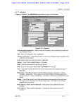
3. Set the Modem Properties
− Back in the Modems Properties dialog box, select the new modem (Standard 19200 bps Modem) and
then click Properties.
− In the Standard 19200 bps Modem Properties dialog box (cf. figure 10), under the General tab, ensure
that Communications Port (COM1) is selected as the Port. Change the Maximum Speed to 19200.
Figure 10: Modem
Properties Dialog Box
.
− Under the Connection tab, ensure that the modem is configured for 8 data bits, no parity, and one
stop bit. Then click Advanced.
− In the Advanced Connection Settings dialog box, ensure that the Use flow control and Hardware
(RTS/CTS) options are enabled. Then click OK.
− Under the Connection tab, click Port Settings.
− In the Port Settings dialog box, ensure that the Use FIFO Buffers option is disabled. Then click OK.
− Click OK to close the Standard 19200 bps Modem Properties dialog box and Close to close the
Modem Properties dialog box.
4. Create a Dial-Up Networking Connection
− Double-click on My Computer, and then on Dial-Up Networking.
− In the Dial-Up Networking dialog box, double-click the Make New Connection icon.
− In the initial dialog box of the Make New Connection wizard, where it asks you to enter a name for the
computer you are dialling, enter BSM Ensure that the selected modem is Standard 19200 bps Modem.
Then click Next.
− In the next dialog box, enter any number as the phone number (for example, just the digit 1 by itself).
Then click Next.
− In the next dialog box, click Finish.
User manual - A43Z0090004-2
page 31/34
5. Set the Dial-Up Networking Properties
− In the Dial-Up Networking dialog box, point to the new BSM connection icon. Click the right mouse
button and select Properties.
− Under the General tab, ensure that Standard 19200 bps Modem is selected at the bottom.
− Under the Server Types tab (cf. figure 11), ensure that the type of dial-up server is set to PPP:
Internet, Windows NT Server, Windows 98 (or similar PPP setting under Windows 95/ME). Ensure
that all Advanced options are disabled. Under Allowed network protocols, select TCP/IP and ensure
that all other network protocols are disabled.
Figure 11: Dial-Up Networking
Properties - Server Types – Windows 98
.
User manual - A43Z0090004-2
page 32/34
− Under the Server Types tab, click TCP/IP Settings.
− In the TCP/IP Settings dialog box (cf. figure 12), click Specify an IP address and type in the following
IP address: 192.168.11.2. The Server assigned name server addresses option should be enabled. The
options Use IP header compression and Use fault gateway on remote network should be disabled.
When all options are set correctly, click OK.
Figure 12: TCP IP
Settings
− Under the Scripting tab, ensure that the Start terminal screen minimised is enabled.
− If there is a Multilink tab, ensure that its Do. not use additional devices option is checked, and click
OK.
− Point to the BSM icon, click the right mouse button, select Create Shortcut, and answer Yes. A
shortcut to the BSM icon should appear on the Windows desktop.
6. Set-up the internet properties
− Click Start, Settings, and Control Panel.
− Look in the control panel for any WINSOCK software icons and make sure to turn-off (unchecked)
any proxy server settings. With improper WINSOCK proxy setting, the explorer will dial out but will
not communicate through a COM port when locating a URL.
− In the Control Panel, double-click the Internet icon.
− Under the Security tab, select Trusted Sites and click on Add Sites…. Check that Require server
verification (https: ) for all sites in the zone is disabled. In the Zone field write "http://Gensys" and
click on Add. Click OK.
− Under the Security tab, Customize…. In Java (or Java VM for 95, or Microsoft VM for ME) and
Java permissions, select Custom. Click on Java Custom Settings. Under the Edit permissions tab,
unable the Run Unsigned Content. Click OK.
− Under the Connection tab, click on Never establish connection. Click on Parameters, and check that
Use a proxy server is disabled. You can also check the settings you already done.
− Under the Advanced tab, in the Java VM field (Microsoft VM for ME), check that Java JIT enabled
is selected.
− The BSM must be listed by the DNS as '
BSM'. Done by copying thehosts file in c:\windows
directory.
User manual - A43Z0090004-2
page 33/34
7. Connect the BSM II
− Connect one end of a DB-9 serial cable to COM1 port of the PC. Connect the other end of the cable to
the connector labelled RS232 to PC or modem on the BSM II.
− Double-click the Shortcut to BSM icon. In the Connect To dialog box, click CONNECT.
− A valid connection is indicated by a connection icon in the status bar of Windows 95/98.
8. View Web Pages from the BSM II Web Server
After the TCP/IP connection has been established with BSM II, you can view BSM II menus with any standard
web browser such as Netscape or Internet Explorer.
− Start the web browser under Windows 95/98.
− In the “Location” or “Address” field of the web browser, enter the URL of the BSM II: http://Bsm
− The BSM II password page should appear in the browser window. Enter a password.
− You can now browse through the different BSM II menus.
− To close the connection, double-click the connection icon in the status bar of Windows 95/98/ME. In
the Connected To BSM dialog box, click Disconnect.
User manual - A43Z0090004-2
page 34/34