1
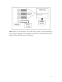
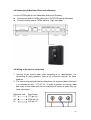
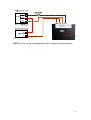
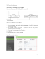
IP5815 Door Phone
User Manual
V1.0
2015/10/15
Index
1. Gift box content............................................................................................3
2. Operation guidelines ....................................................................................4
3. Product Overview.........................................................................................5
3.1 Product intended use ..........................................................................5
3.2 Functions of the system ......................................................................5
3.3 IP5815 Video door phone features .....................................................5
3.4 Video Door Phone Specification .........................................................6
3.5 eGateway Specification ......................................................................6
3.6 System architecture ............................................................................7
3.7 System components identification ......................................................8
3.8 Description of functions.......................................................................8
3.9 LED colors indication ........................................................................10
4. Installation.................................................................................................. 11
4.1 Selecting a location for Video Door Phone ....................................... 11
4.2 Installing Video Door Phone .............................................................12
4.3 Preparation for wiring........................................................................13
4.4 Connecting Video Door Phone and eGateway .................................16
4.5 Wiring of the electric strike/lock ........................................................16
5. Setting WiFi router and eGateway .............................................................18
5.1 Recommended characteristics for the WiFi router ............................18
5.2 Recommended characteristics for the Android device ......................18
5.3 Recommended characteristics for the iOS device ............................18
5.4 Connection diagram..........................................................................19
5.5 Internet/WAN Connection Setting .....................................................19
5.6 LAN Connection Setting ...................................................................21
5.7 e-Gateway Setting ............................................................................22
6. Mobile device pairing and setting...............................................................24
6.1 Mobile device paring with eGateway.................................................24
6.2 Setting Android device to work with Mobile2Door .............................26
2
1. Gift box content
1 x Video Door Phone IP5815 unit
1 x Power adapter for Video Door Phone
1 x eGateway IP5858
1 x 14 pin connector for Video Door Phone IP5815 unit
1 x mounting bracket Video Door Phone IP5815 unit
1x mounting kit
3
Thank you for selecting Smart Bell for your communication and security needs. .
Please read this manual carefully before installation and keep it in a safe place for
future reference
2. Operation guidelines
1. The unit is damaged if dropped. Handle with care.
2. If the unit does not operate properly, unplug the power supply.
3. Due to the environmental sound around the unit, it may hinder smooth
communication, but this is not a malfunction.
4. When outside temperature lowers sharply after rainfall, etc, the inside of the
camera may fog up slightly, causing blurry picture, but this is not a malfunction.
Normal operation will be restored when moisture evaporates.
5. If moving the unit from a warm to cold environment, or vise versa, please allow
30 minutes before use.
6. As to other manufacturer’s device (such as door releases) used with this system,
comply with the Specifications and Warranty conditions that the manufacturers
or vendors present.
4
3. Product Overview
3.1 Product intended use
The product that you are about to use is a video intercom system especially
designed for applications in single houses, apartments, and such facilities as office
buildings, factories, schools, hospitals, etc
It provides end users with the ability to answer their door using smartphones, see
live video of who is at their door and have a two-way conversation with the guest
even if the owner is not at home.
Installed separately from the general-purpose internal communications systems,
the system can be used as:
a video door entry system,
emergency announcement system,
rescue assistance system, urgent call system,
public announcement system, and access control system.
NOTE: You can design the system to any scale depending on your needs. Please
contact our support team for more information
3.2 Functions of the system
IP enabled doorphone: follows industry standard. Based on SIP (session
initiation protocol)
Mobile access: uses mobile App to connect with Android and iOS
smartphones/tablets
Multiple remote Users: registers up to 8 mobile devices
Quality video and Full Duplex Audio
Access control: inbuilt RFID card reader
Remote door release: works with electronic locks that can be released via
mobile App
3.3 IP5815 Video door phone features
IP addressable video door station
Monitoring of view of the front (rear) door or a visitor at any time of day and
night
High-performance HD video camera providing WXGA (1280 x 800) at 30fps
or 720p HD format with high sensitivity
5
2-Way audio
DI / DO dry control for door release
Taking snapshots of the visitor automatically once the call button is pressed
Night vision
Built-in RFID sensor module
3.4 Video Door Phone Specification
Camera
1M pixel CMOS sensor
Night Light
2 x LED
HW Specific
1 * ISO14443 Card Reader, support RFID card
1 * Door Lock port for power lock
Speaker(8Ω/1W) x1, Microphone(-62±2dB) x1
1 * Ethernet Interface
Power supply: external 12V power supply
Support H.264 720P
Support protocol
SIP 2.0 (RFC 3261)/TCP/IP/UDP, RTP, ARP, ICMP, DHCP,
DNS, NTP
Audio codec: G.711 (A/u-law) , G.729
Audio quality: packet loss concealment, echo suppressor
Video codec: H.264 baseline real-time video codec
Automatic firmware and configuration update via TFTP
3.5 eGateway Specification
FE
1 x FE/fast Ethernet for WAN
4 x FE/fast Ethernet for LAN
USB Host 2.0
Support Z-wave Dongle plug in
Digital Input & output
8 x DI ; 4 x DO
RS-485
1 X RS-485,
For connecting access control/alarm device & digital
input/output device extension
Dimension
170 mm * 115 mm * 37mm (L x W x H)
Support protocol
SIP 2.0 (RFC 3261)/TCP/IP/UDP, RTP, HTTP, ARP, ICMP,
DHCP, DNS, TFTP, NTP
Power
12V-24V,2A-1A
6
3.6 System architecture
7
3.7 System components identification
Door phone unit
3.8 Description of functions
The figure below illustrates the front view of the IP5815. Follow the point
numbers to find the description of the door phone components’ functions
8
Front view of the IP5815 Video door phone
Part name
Card reader
White LED
Camera
Speaker
LED
Calling button
Microphone
Description of functions
RFID card reader control
Night vision to make sure that the user gets
clear image
Seeing the video of the visitor once the door
bell button is pressed
Monitoring of the front door
Ring tone
Talking
Status indicator
Red LED light is used to indicate registration
status or reset to default status
Green LED is sued to indicate that the call is
connected or upgrade process is finished
Used for calling the door, upgrade, reset to
default
Voice communication
9
Back view of the IP5815 Video door phone
3.9 LED colors indication
LED colors are associated with the door phone button and follow this
guideline:
LED
Color
Status
Description
Steady
Choose to emergency upgrade or reset
default when you see this LED status.
Choose to emergency upgrade or reset
default after push Calling Button, or all
used lines cannot register to the SIP
register servers.
Emergency upgrade or register process
is underway.
Idle status or voice is not connected.
Voice is connected or the emergency
upgrade process is finished.
The process of reset default is finished.
Idle status or voice is not connected.
Blinking Rapidly
LED
Red
Blinking Slowly
Off
Steady
Green
Blinking Slowly
Off
10
4. Installation
4.1 Selecting a location for Video Door Phone
Areas to avoid when mounting the Video Door Phone Unit:
1. Avoid areas that are subject to vibration or shock
2. Avoid areas where rain or water may directly hit the unit. Unit is not
water-resistant and can be damaged if sprayed with high pressure water.
3. Installation in an enclosed area may cause echo
4. Keep the unit more than 1m (3,3’) away from radio or TV
5. Keep the intercom wires more than 30 cm (12’) away from AC100-240V
wiring. AC induces noise and/or unit malfunction could result.
6. Install the unit in the area that will be accessible for future inspections,
repairs, and maintenance.
7. Do not locate the unit in a location with restricted access. It impedes
maintenance inspection or repairs. Also, unit trouble could result.
8. Avoid areas where broadcasting antennas are close by, the intercom
system maybe affected by radio frequency interference.
9. Installation if following locations may affect the video image provided by the
device:
11
4.2 Installing Video Door Phone
NOTE: Verify transformer power rating. Power must be supplied in the range
13V ~ 20 AC.
1. Make sure that outlet’s power (AC 13V ~ 20V) is off when wiring
Doorphone. Keep power off until the wire connection has been complete.
2. Fasten the Doorphone wall mount bracket to the outlet box.
3. Connect transformer output power wires (AC 13V ~ 20V) to the power
wires of Doorphone.
4. Put the Doorphone on the wall mount bracket.
5. Use the special screw wrench to fasten special screw at the bottom of the
Doorphone.
Transformer
power wires
Output: 16V AC
12
4.3 Preparation for wiring
1. Please prepare your own CAT5e cable and follow the operation guidelines
as below:
Make sure that the resistance of CAT5e < 0.094 Ohm/m.
Use a straight-through cable for connecting units.
Do not bend the cables to an extent where the
radius is less than 25 mm (1”). It may result in
communication failure
Do not remove the CAT5e cable jacket more
than necessary
Arrange the color code of the RJ45 connections
in accordance with EIA/TIA-568A or 568B.
Be sure to check the condition of cable connections with a LAN checker
before connecting with a LAN cable.
An RJ45 connector with a cover cannot be
connected to the port for CAT5e on IP master
stations or IP door stations. Use a cable without a
cover.
Do not pull or put excess strain on CAT5e cables.
2. 14 pin connecter with RJ45 and DC plug is provided with the device
3. Twist pair definition:
Pair1 : Pin1 & Pin 2.
Pair2 : Pin3 & Pin 4.
Pair3 : Pin5 & Pin 6.
Pair4 : Pin7 & Pin 8.
13
4. Color of Wire and Identification
5. Conventional rule
Power supply by e-Gateway for 12V/2A DC, distance is less or equal than
30 meters.
Power supply by e-Gateway for 24V/1A DC, distance is less or equal than
100 meters.
14
NOTE: When the link distance is over 100 meters, power must be provided by
external power adapter, and an individual switch/hub is required for connection
between Video Door Phone and e-Gateway.
15
4.4 Connecting Video Door Phone and eGateway
Use the CAT5e cable to link Video door phone to e-Gateway.
Connect one end of CAT5e cable to the OUTDOOR port of eGateway.
Connect another end of CAT5e cable to 14 pin connecter.
outdoor
4.5 Wiring of the electric strike/lock
1. Connect to the electric door strike according to its specifications. For
connecting 3rd party products, refer to the instruction manuals for those
products.
2. The connectivity point defined on door phone for electronic door strike/lock
is in accordance with – PT, AC, EL. In order to prevent mis-wiring, label
both ends of each cable with the unit and terminal names to which they are
to be connected.
Electronic lock
PT
AC
EL
Door Phone
PT (pin 14)
COM (pin 13)
NO (pin 12)
16
New back panel
With RJ45 connector
& wire set
0
NOTE: Do not use the unoccupied terminals and ports for other purposes
17
5. Setting WiFi router and eGateway
NOTE: to ensure the smooth operation of the product, we highly recommend
the required characteristics as presented below
5.1 Recommended characteristics for the WiFi router
Standard: 802.11 b/g/n
Wireless Signal Rate: 300 Mbps
Antenna Gain: 2 dBi
QoS Management
DDNS Support
Reference models: TP-Link TL-WR841N(D), D-Link DIR-615
5.2 Recommended characteristics for the Android device
CPU clock: 1024MHz or above
Memory size: 1GB ROM + 512 MB RAM or above
LCD Resolution: 800 * 480 or above
LCD Size: 3.5” or above
Operation System: Android 2.3 or above
Reference model: Samsung SII, HTC ONE Series
5.3 Recommended characteristics for the iOS device
Reference model: iPhone4 or above
18
5.4 Connection diagram
Connect Wi-Fi router WAN to ADSL modem
Connect e-Gateway (eGW) WAN to Wi-Fi router LAN
5.5 Internet/WAN Connection Setting
1. On your computer, login to the administration page of the Wi-Fi router and
proceed with setting.
2. Set up WAN / Internet connection in accordance with the ISP provider
Internet connection information.
3. There are 2 ways to acquire the IP address:
static IP
dynamic IP (such as: DHCP, PPPoE)
Static IP connection setting
19
Dynamic IP (DHCP/PPPoE) connection setting
NOTE: For the details of DDNS settings please refer to the Wi-Fi router
Instructions.
When the Internet connection type is Dynamic IP, it is also required to setup
the DDNS.
1. Select DDNS provider
2. Input your account, password and registered domain name
20
5.6 LAN Connection Setting
1. Please enable DHCP Server and set different IP segment with
e-Gateway’s.
2. The current e-Gateway default LAN IP segment is 192.168.0.xxx; avoid
using this IP segment for DHCP setting of the Wi-Fi router.
3. Reserve a fixed IP address to e-Gateway
4. Set IP address of e-Gateway to DMZ
TCP/UDP Ports Definition for the Video Door Phone System
21
NOTE: This table lists TCP / UDP ports used by Tecom’s system. Do not use
these ports for other network applications.
Port
443
TCP / UDP
TCP
80
TCP
5070
UDP
48999
49004
49006
4903149070
TCP
TCP
TCP
UDP
Direction
WAN
Description
HTTPS port of web management, open it
when remote security http access is
enabled
LAN/WAN HTTPS port of web management, open it
when remote normal http access is
enabled
LAN/WAN Local SIP proxy signal port (SIP port can
be changed by user)
LAN/WAN Communication port (Intercom)
LAN/WAN
LAN/WAN
WAN
5.7 e-Gateway Setting
1. Set WAN Connection type to DHCP (Default Setting).
2. Set DHCP Type of LAN to “Server” mode (Default Setting).
22
3. To secure your system against unwanted outside intrusion (hacking), we
strongly recommend that you do is change all of the System’s Passwords!
NOTE: Make sure to make a note of your new password!
23
6. Mobile device pairing and setting
6.1 Mobile device paring with eGateway
1. Connect PC to the LAN1 or LAN2 Port of e-Gateway,
2. Open the browser to log in to the e-Gateway Web page (the default IP:
192.168.0.10, Account: admin, Password: admin)
3. Click the Settings Unit pairing.
4. Click “Add” button to add a new Unit and check it.
4. Follow the steps to input the unit information:
Name: enter the name according to personal needs.
Type: SMART PHONE
Account: Please fill in the range of 100 to 109 numbers, make sure that
the number you input is not used by other devices.
Password: enter the password according to personal needs.
Press SAVE
Press – START PAIRING
24
25
6.2 Setting Android device to work with Mobile2Door
1. Follow the steps below to connect your mobile device to the intercom
system WiFi
Enable WiFi by tapping mobile device’s “Settings”
“WiFi settings”
In the “Wi-Fi networks” list, choose SSID of Wi-Fi AP (For Example, the
SSID is “Intercom Wi-Fi”)
2. In Google Play Store find “Mobile2Door” App. Tap installation button and
complete the App installation process on your Android device. After the
installation is complete, “Mobile2Door” icon will appear on your All Apps
page.
26
3. Tap “Mobile2Door” icon to start using the App. The following registration
screen will appear.
4. Fill out the required items, then tap the “Registration” button to start the
registration procedure.
“Extension No”: equal to “Account” information of eGateway - admin by
default or the account number that you used for eGateway pairing with
mobile device
“Registration No”: equal to “Password” information of eGateway - admin
by default or the password that you used for eGateway pairing with mobile
device
“Default Server Address” => Enter the e-GW WAN IP assigned by Wi-Fi
Router.
“Server Address” => Enter the Wi-Fi Router WAN IP.
The main page will pop-out when registration is completion.
27
5. Enabling the mobile device to be registered to e-GW via 3G/WAN, user is
required to fill-in account/password, IP address/WAN of e-GW.
“Default Server Address”: Enter the e-GW WAN IP assigned by Wi-Fi
Router. When the WAN connection type of eGW set as DHCP, the WAN IP
address of eGW is dynamic IP address. It is essential to have the correct
IP address through DDNS
“Server Address”: Enter the Host Name that you registered with your
DDNS service provider.
28
Setting iOS device to work with Mobile2Door
1. Follow the steps below to connect your mobile device to the intercom
system WiFi
Click on “Settings” then select “ Wi-Fi”.
In the “Choose A Network” list, choose the SSID of Wi-Fi AP (For Example,
the SSID is Intercom Wi-Fi)
Identify the system as connected, the SSID displayed above the “Choose
A Network”.
2. In App Store find “Mobile2Door” App. Tap installation button and complete
the App installation process on your Android device. After the installation is
complete, “Mobile2Door” icon will appear on your All Apps page.
29
3. Tap “Settings” and choose “Mobile2door” in the Settings screen.
4. Fill in the correct registration information
“Account”: enter account as inputted in e-gateway (admin by default).
“Password”: enter password as inputted in e-gateway (admin by default).
“Intranet Server IP”: enter the e-GW WAN IP assigned by Wi-Fi Router.
“Internet Server IP”: enter the Wi-Fi Router WAN IP
30
5. Enabling the mobile device to be registered to e-GW via 3G/WAN, user is
required to fill-in account/password, IP address/WAN of e-GW. WAN
connection type set as DHCP on Wi-Fi router, the IP address will be
acquired a dynamic IP address from DDNS.
6. After confirming that the iPhone is connected to WiFi router and completing
registration procedure tap on the desktop Mobile2door to start using
Mobile2door
31