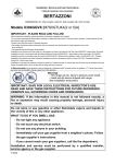
1
IMPORTANT SAFETY INFORMATION WARNING PLEASE READ AND FOLLOW THESE IMPORTANT INSTRUCTIONS FOR THE SAFETY OF YOUR HOME AND OF THE PEOPLE LIVING IN IT. Read this instruction booklet before installing and using the appliance Save this Manual for local electrical inspector’s use. Read this instruction booklet before installing and using the appliance. Read and save these instructions for future reference. The manufacturer will not be responsible for any damage to property or to persons caused by incorrect installation or improper use of the appliance. Observe all governing codes, ordinances and regulations. The manufacturer reserves the right to make changes to its products when considered necessary and useful, without affecting the essential safety and operating characteristics. WARNING! If the information in this manual is not followed exactly, a fire or explosion may result causing property damage, personal injury or death. This appliance has been designed for non‐ professional, domestic use only. ‐Do not store or use gasoline or other flammable substances in the vicinity of this or any other appliance. Do not use this appliance to heat a room. Do not place any pot or pan on the open oven door. The door is made of glass and it can break if loaded with a weight. ‐ Installation and service must be performed by a qualified installer or a service agency. Before beginning installation, please read these instructions completely and carefully. Do not remove permanently affixed labels, warnings, or plates from the product. This may void the warranty. ‐Please observe all local and national codes and ordinances. Please ensure the range is properly grounded. The installer should leave these instructions with the consumer who should retain for local inspector's use and for future reference. The plug should always be accessible. Installation must conform with local codes or in the absence of codes. Electrical installation must be in accordance with the National Electrical Code, ANSI/NFPA70 ‐ latest edition and/or local codes. Electrical installation must be in accordance with the current CSA C22.1 Canadian Electrical Codes Part 1 and/or local codes. Warning! Tip‐Over Hazard A child or adult can tip the range and be killed Install anti‐tip device to range and/or structure per installations instructions Engage the range to the anti‐tip device installed WARNING! to the structure Re‐engage anti‐tip device if range is moved Failure to follow these instructions can result in death or serious burns to children and adults. Show specific manufacturer illustrations and instructions for checking the installations of anti‐ tip device. 1 From the desk of the President Dear new owner of a Bertazzoni product, I want to thank you for choosing one of our beautiful PRO ranges. We know that you have many brands and products to choose from and we are thrilled that you have decided to take one of our products into your home. We take as much pride in making our ranges as we hope you will in owning them. My family started manufacturing cooking appliances in 1882. Each of our products is a blend of Italian design finesse and superior appliance technology. While we can not replace your unique talent at cooking delicious recipes for yourself, your family and your friends, we try our best to make cooking easier, more effective and more fun. BERTAZZONI SpA Via Palazzina 8 42016 Guastalla RE ITALY WWW.BERTAZZONI.COM Our appliances are designed according to the strictest safety and performance standard for the European and the North American market. We follow the most advanced manufacturing philosophy. Each appliance leaves the factory after thorough quality inspection and testing. Our distributors and our service partners are ready to answer any questions you may have regarding how to install, use and care for your Bertazzoni product. 5000980 This manual will help you learn to use the product in the safest and most effective manner and care for it so that it may give you the highest satisfaction for years to come. The manual also includes directions for the professional installer that will install the product in your home. We recommend using factory‐trained professionals for the delicate task of installing and testing appliances in your home. Please call Customer Service if you need help locating a factory‐trained professional installer in your area. Model PRO304INMXE [M70Q6ZU1XE.UP] Model MAS304INMXE [M70Q6ZA1XE.UP] Please keep this manual for future use. Grazie! 2 TABLE OF CONTENTS IMPORTANT SAFETY INFORMATION ........................................................................................................................ 1 WARRANTY AND SERVICE ........................................................................................................................................ 4 BEFORE INSTALLATION ............................................................................................................................................ 6 INSTALLING THE LEGS .............................................................................................................................................. 6 INSTALLING THE BACKGUARD ............................................................................................................................... …7 INSTALLATION REQUIREMENTS ............................................................................................................................... 8 EXHAUST HOOD INSTALLATION ............................................................................................................................... 9 ELECTRICAL CONNECTION ...................................................................................................................................... 10 APPLIANCE SERVING .............................................................................................................................................. 11 WIRING DIAGRAM ................................................................................................................................................. 12 INSTALLATION CHECKLIST ...................................................................................................................................... 13 FINAL PREPARATION ............................................................................................................................................. 13 USER MANUAL ...................................................................................................................................................... 14 ROOM VENTILATION ............................................................................................................................................. 14 SURFACE HOTPLATES ............................................................................................................................................. 17 PAN PRESENT DEVICE ............................................................................................................................................ 17 RESIDUAL HEAT ..................................................................................................................................................... 17 LOCKING‐OUT THE COOKTOP AREA ....................................................................................................................... 17 IMPORTANT! ......................................................................................................................................................... 18 SURFACE COOKING ................................................................................................................................................ 18 OVEN COOKING ..................................................................................................................................................... 19 USING THE OVEN ................................................................................................................................................... 20 BAKE .................................................................................................................................................................. 21 PREHEATING THE OVEN ......................................................................................................................................... 21 GETTING THE BEST RESULTS ................................................................................................................................... 21 BAKEWARE TYPE ................................................................................................................................................... 21 BAKE RACK POSITIONS .......................................................................................................................................... 21 CONVECTION ......................................................................................................................................................... 21 RACK POSITIONS ................................................................................................................................................... 22 BAKING RECOMMENDATIONS ............................................................................................................................... 22 BROIL / CONVECTION BROIL .................................................................................................................................. 23 BROILING AND ROASTING RECOMMENDATIONS ................................................................................................... 24 MAINTAINING YOUR RANGE .................................................................................................................................. 25 CLEANING YOUR RANGE ........................................................................................................................................ 25 TROUBLESHOOTING GUIDE .................................................................................................................................... 26 IMPORTANT APPLIANCE INFORMATION ................................................................................................................ 27 3 Please kindly register on our web site www.bertazzoni.com to validate your new product warranty and help us to assist you better in case of any inconvenience. TWO YEAR LIMITED WARRANTY The warranties provided by Bertazzoni Spa in this statement apply exclusively to Bertazzoni appliances and accessories sold as new products to the original owner by a Bertazzoni authorized distributor, retailer, dealer or service center and installed in the United States and Canada. The warranties provided in this statement are not transferable and have validity from the date of installation. COVERAGE INFORMATION Bertazzoni SpA will repair or replace any component part which fails or proves defective due to materials and/or workmanship within 2 years from the date of installation and under conditions of normal residential use. Repair or replacement will be free of charge, including labor at standard rates and shipping expenses. Repair service must be performed by a Bertazzoni Authorized Service Center during normal working hours. COSMETIC WARRANTY Bertazzoni will cover parts showing cosmetic defects in material and workmanship for a period of thirty (30) days from date of installation of the unit. This coverage will include scratches, stains, surface imperfections on stainless steel, paint and porcelain, with the exclusion of slight differences in color due to materials and painting/enamelling technologies. Exclusions are labor costs, B stock items, out‐of‐box appliances and display units. HOW TO OBTAIN SERVICE To obtain warranty service please contact Bertazzoni Customer Service at the numbers below and provide model number, serial number and date of purchase. ENGLISH 866 905 0010 ‐ FRANCAIS 800 561 7265 Save proof of original purchase or of original installation to establish warranty period. Copy of the product serial tag is affixed to the back cover of the instruction manual. 1 WHAT IS NOT COVERED The product used in any commercial application 2 Repair service provided by other than a Bertazzoni authorized service agency. 3 Damage or repair service to correct service provided by an unauthorized agency or the use of unauthorized parts. 4 Installation not in accordance with local electrical codes or plumbing codes. 5 Defects or damage due to improper storage of the product. 6 Defects or damage or missing parts on products sold out of the original factory packaging or from displays. 7 Service calls or repairs to correct the installation of the product and/or related accessories. 8 Service calls to connect, convert or otherwise repair the electrical wiring and/or gas line to properly use the product. 9 Service calls to provide instructions on the use of a Bertazzoni product. 10 Repair service due to product usage in manner other than what is normal and customary for home use. 11 Replacement of wear and tear parts 12 Replacement of glasses and light bulbs if they are claimed to have failed later than 30 days after installation and in no case later than 4 months after date of purchase 13 Defects and damages arising from accident, alteration, misuse, abuse, improper installation. 14 Defects and damages arising from transportation of the product to the home of the owner. 15 Defects and damage arising from external forces beyond the control of Bertazzoni SpA such as fire, flood, earthquakes and other acts of God. In case the product will be installed in a remote area, where certified trained technicians are not reasonably available, the customer will be responsible for the transportation costs for the delivery of the product to the nearest authorized service center or for the displacement costs of a certified trained technician. Bertazzoni does not assume any responsibility for incidental or consequential damages. Some states do not allow the exclusion or limitation of incidental or consequential damages, so the above limitation or exclusion may not apply to you. This warranty gives you specific legal rights and you may also have other rights which may vary from state to state or province to province. 4 PRODUCT SPECIFICATIONS Dimensions (insert drawings front, side and back) 5 BEFORE INSTALLATION INSTALLING THE LEGS This appliance shall only be installed by an authorized professional. Bertazzoni ranges must be used only with the legs properly installed. This appliance shall be installed in accordance with the manufacturer’s installation instructions. Four height‐adjustable legs are shipped with the range in the polystyrene container situated over the appliance. This appliance must be installed in accordance with the norms & standards of the country where it will be installed. The installation of this appliance must conform to local codes and ordinances . In the absence of local codes, Installations must conforms to American National Standards. Before installing the legs, position the appliance near its final location as the legs are not suitable for moving the appliance over long distances. After unpacking the range, raise it enough to insert the legs in the appropriate receptacles situated on the lower part of the appliance. Lower the range gently to keep any undue strain from legs and mounting hardware. If possible use a pallet or lift jack instead of tilting the unit. The appliance, when installed, must be electrically grounded in accordance with local codes or, in the absence of local codes, with the National Electrical Code, ANSI/NFPA 70. All opening and holes in the wall and floor, back and under the appliance shall be sealed before installation of the appliance. Adjust leg height to the desired level by twisting the inside portion of the leg assembly until the proper height is reached. Check with a level that the cooktop is perfectly level. WARNING! Do not use aerosol sprays in the vicinity of this appliance while it is in operation ROOM VENTILATION: An exhaust fan may be used with the appliance; in each case it shall be installed in conformity with the appropriate national and local standards. Exhaust hood operation may affect other vented appliances; in each case it shall be installed in conformity with the appropriate national and local standards. 6 INSTALLING THE BACKGUARD Assemble back part with front part of the backguard and fix them with a screws supplied with the backguard kit. The back guard must be installed prior to operation of the appliance for appropriate ventilation of the oven compartment. Remove n°2 screws fixing worktop as shown below. Place front part of the backguard and attach it from bottom side with the two removed screw (point 2) as shown below. Fix the front part of the backguard with the screws supplied with the backguard kit. 7 INSTALLING THE ANTI‐TIP Stability DEVICE INSTALLATION REQUIREMENTS ELECTRICAL The anti‐tip bracket shipped with the range must be properly secured to the rear wall as shown in the picture below. A properly grounded and horizontally‐mounted electrical receptacle Type NEMA 14‐50R should be installed no higher than 3" (7.6 cm) above the floor, no less than 2” (5 cm) and no more than 11” (28 cm) from the left side (facing product); refer to ELECTRICAL CONNECTION section pag. 12. The height of the bracket from the floor must be determined after the range legs have been adjusted to the desired height and after the range has been levelled. Measure the distance from the floor to the bottom of the anti‐tip bracket receptacle on the back of the appliance. Check all local code requirements. Position the two anti‐tip brackets on the wall at the desired height plus 1/8" (0.32 cm). The brackets must be placed at 2”5/16 (6,0 cm) from the side of the range. The distance between the two bracket is 25”1/4 (64,1 cm). Secure the brackets to the wall with appropriate hardware. Slide the range against the wall until the brackets are fully inserted into their receptacles on the back of the range. 8 INSTALLATION ADJACENT TO KITCHEN CABINETS EXHAUST HOOD INSTALLATION This range will best perform when used with PRO line Bertazzoni exhaust hoods. These hoods have been designed to work in conjunction with the Bertazzoni range and have the same finish for a perfect look. WARNING To eliminate the risk of burns or fire by reaching over heated surface units, cabinet storage space located above the surface units should be avoided. If cabinet storage is to be provided, the risk can be reduced by installing a range hood that projects horizontally a minimum of 5 inches beyond the bottom of the cabinets. For maximum performance, the height of the bottom of the hood from the worktop should be between 25 1/2" (65 cm) and 31 1/2" (80 cm). This would typically result in the bottom of the hood being 61 1/2" (156.2 cm) to 67 1/2" (171.5 cm) above the floor. These measurements provide for safe and efficient operation of the hood. This range may be installed directly adjacent to existing countertop high cabinets (36" or 91.5 cm from the floor). Before installation of the exhaust hood, consult local or regional building and installation codes for additional specific clearance requirements. For the best look, the worktop should be level with the cabinet countertop. This can be accomplished by raising the unit using the adjustment spindles on the legs. Refer to the range hood installation instructions provided by the manufacturer for additional information. ATTENTION: the range CANNOT be installed directly adjacent to kitchen walls, tall cabinets, tall appliances, or other vertical surfaces above 36" (91.4 cm) high. The minimum side clearance in such cases is 6" (15.2 cm). Wall cabinets with minimum side clearance must be installed 18" (45.7 cm) above the countertop with countertop height between 35 ½” (90.2 cm) and 37 ¼” (94.6 cm). The maximum depth of wall cabinets above the range shall be 13" (33.0 cm) A B C D E F 30” (76,2 cm) 36” (91,5 cm) 13” (33,0 cm) 18” (45,7 cm) 35”1/2(90,2 cm) / 37” ¼ (94,6 cm) 6” (15,2 cm) 9 ‐ Connect the NEUTRAL receptacle terminal to the incoming NEUTRAL (WHITE) electrical supply wire ELECTRICAL CONNECTION The appliance shall be connected to a single phase electric line rated at 120/208Vac or 120/240Vac and 60Hz frequency. Electric power rating: ‐ 120/208Vac: 9800 Watt or 44 A max. ‐ 120/240Vac: 10500 Watt or 45,5 A max. Oven heating elements power rating: ‐ Oven bake element = 1600 Watt ‐ Oven circular element = 2800 Watt ‐ Oven double broil element = 1200 + 1800 Watt Induction heating elements power rating: ‐ 210 induction element = 2300 – 3700 Watt ‐ 180 induction element = 1850 – 3000 Watt (nr.2 zones) ‐ 145 induction element = 1400 – 2200 Watt Install a suitable electric power supply receptacle connection type NEMA 14‐50R able to support a load of at least 40 A (per line) according to local code requirements. For four or three wires power supply connection system see diagram below. ‐ Connect the GROUND receptacle terminal to the incoming GROUND (GREEN) electrical supply wire OPTION 2 ‐ THREE‐Wires connection: ‐ Connect the L1 receptacle terminal to the incoming BLACK electrical supply wire (L1‐hot wire) ‐ Connect the L2 receptacle terminal to the incoming RED electrical supply wire (L2‐hot wire) ‐ Connect the NEUTRAL with the GROUND receptacle terminal to the incoming NEUTRAL (WHITE) electrical supply wire DO NOT USE EXTENSION CORDS WITH THIS APPLIANCE AS IT MAY RESULT IN FIRE, ELECTRIC SHOCK OR OTHER type of PERSONAL INJURY. The appliance is equipped at the factory with an electric supply cord set 4 wires type with ring terminals (L1, L2, N, Ground) suitable for range use UL/CSA listed type SRDT/DRT 2x6AWG (L1, L2)+2x8AWG (N, G) rated 300V, 50A with fused plug type NEMA 14‐50P; cable length 1,5 m.; in case the supply cord set must be replaced, it shall be replaced with an identical set having the same technical specs and following carefully the instructions and diagrams below: 1) Disconnect appliance from electrical power supply receptacle 2) Slide out the appliance from installation place to access to back enclosure panel 3) Remove back enclosure panel by removing the 6 screws as shown below 4) Loose strain relief by unscrewing the two strain relief's scr ews as in diagram. FOUR-WIRE CONN.RECEPTACLE NEMA 14-50R THREE-WIRE CONN.RECEPTACLE NEMA 14-50R Check your local code for which of the options below should be used in grounding the receptacle power supply connections. OPTION 1 – FOUR Wires connection: ‐ Connect the L1 receptacle terminal to the incoming BLACK electrical supply wire (L1‐hot wire) ‐ Connect the L2 receptacle terminal to the incoming RED electrical supply wire (L2‐hot wire) 10 5) Remove damaged supply cord set by taking off the 4 electrical connection screws (block L1, N, L2 and Ground screw, see diagram) 6) Insert the new supply cord set in the strain relief and lock it with two strain relief's screws in suitable position. 7) Fix well the ring terminals G, L1, N, L2 of the new supply cord set as shown in diagram with its 4 screws 8) Re‐install the back enclosure panel with 6 screws 9) Slide the appliance back into its proper location 10) Re‐connect the appliance to the electrical power. ELECTRICAL GROUNDING This appliance is equipped with a four‐prong plug for your protection against shock hazard and should be plugged directly into a properly grounded receptacle. Do not cut or remove the grounding prong from this plug. WARNING! ELECTRICAL SHOCK HAZARD Disconnect electrical power at the circuit breaker box or fuse box before installing the appliance. Provide appropriate ground for the appliance. Use copper conductors only. Failure to follow these instructions could result in serious injury or death CAUTION Label all wires prior to disconnecting when servicing controls. Wiring errors can cause improper and dangerous operation. Verify proper operation after servicing APPLIANCE SERVING Before carrying any servicing operation disconnect the appliance from gas and electric supply and extra appliance from final installation place in order to have access to the appliance for proper servicing intervention. 11 WIRING DIAGRAM 12 INSTALLATION Checklist FINAL PREPARATION 1. Is the range mounted on its legs? All stainless steel body parts should be wiped with hot, soapy water and with a liquid stainless steel cleanser. 2. Is the back guard securely connected? If build‐up occurs, do not use steel wool, abrasive cloths, cleaners, or powders! If it is necessary to scrape stainless steel to remove encrusted materials, soak with hot, wet cloths to loosen the material, then use a wood or nylon scraper. Do not use a metal knife, spatula, or any other metal tool to scrape stainless steel! Scratches are almost impossible to remove. 3. Has the anti‐tip device been properly installed? 4. Does the clearance from the side cabinets comply with the manufacturers directions? 5. Is the electricity properly grounded? Before using the oven for food preparation, wash the cavity thoroughly with a warm soap and water solution to remove film residues and any dust or debris from installation, then rinse and wiped dry. 13 USER MANUAL Keep oven vent ducts unobstructed. IMPORTANT Take care of reset all worktop / oven/broiler burners controls in OFF position after use of the appliance. WARNING! Always place oven racks in desired location when oven is cool. If rack must be moved while oven is hot, do not let potholder contact hot heating element in oven. Do not touch heating elements or interior surfaces of oven. Proper Installation. Be sure your appliance is properly installed and grounded by a qualified technician. Do not clean oven door gasket. The door gasket is essential for a good seal. Care should be taken not to rub, damage, or move the gasket. Do not leave children alone. Children should not be left alone or unattended in area where appliance is in use. They should never be allowed to sit or stand on any part of the appliance. Do not use oven cleaning products. No commercial oven cleaner or oven liner protective coating of any kind should be used in or around any part of the oven. Wear proper apparel. Loose‐fitting or hanging garments should never be worn while using the appliance. Clean only parts listed in manual. User servicing. Do not repair or replace any part of the appliance unless specifically recommended in the manual. All other servicing should be referred to a qualified technician. Smother fire or flames or use dry chemical or foam‐type extinguisher. Do not use water on greasefires. ROOM VENTILATION Use only dry potholders. Moist or damp potholders on hot surfaces may result in burns from steam. Do not let potholder touch hot heating elements. Do not use a towel or other bulky cloth. The use of a cooking appliance generates heat and humidity in the room where it is installed. Proper ventilation in the room is needed. Make sure the kitchen is equipped with a range hood of appropriate power (400 CFM minimum). Activate the exhaust fan/range hood when possible. Intensive and continuous use of the appliance may require additional ventilation, for example by opening a window. Do not to cover the holes inside the oven with aluminium foil. Do not to cover the worktop with aluminium foil. Do not store any flammable object or objects under pressure in the storage compartment. Keep the area of operation of the range free from combustible materials, gasoline and other flammable vapours and liquid. Do not store dangerous or flammable materials in the cabinets above the appliance, since this may result in a potential fire hazard. Do not use the appliance for space heating. Do not use aerosol sprays in the vicinity of the appliance while cooking. Do not sit or step on the oven door. Do not use oven compartment for storage. Use Care When Opening Door. Let hot air or steam escape before removing or replacing food Do not heat unopened food containers. Build‐up of pressure may cause container to burst and result in injury. 14 off. USING THE INDUCTION COOKTOP AREA Holding Function The holding function keeps the temperature of the bottoms of pans at about 110°F/42°C or 160°F/70°C . This allows foods to be kept hot with optimal energy consumption and to be heated gently. The holding function can be kept in operation for up to 2 hours. COOKTOP AREA CONTROL KNOB These knobs provide control of the ceramic cooktop area's cooking zones. The zone it controls is shown above eachknob. Turn the knob to the right to set the zone's operating power; the settings range from a minimum of 1 to a maximum of 9. The working power is shown by a display on the cooktop area. The holding function is and is indicated by the relevant symbol on the cooking zones. Heating accelerator COOKTOP AREA Each cooking zone is equipped with a heating accelerator. This system allows the zone to be operated at peak power for a time proportional to the heating power selected. To start the heating accelerator, turn the knob to the left, select setting "A" and then release. The letter "A" will appear on the display on the cooktop area. You now have 3 seconds to select the heating setting of your choice. Once a setting between 1 and 9 has been selected, "A" and the chosen setting will flash in alternation on the display. ' While the heating accelerator is in operation, the heating level can be increased at any time. The "full power" time will be modified accordingly. If the power is reduced by turning the knob anticlockwise, option "A" is automatically deactivated. ATTENTION: Metal items such as cutlery or lids must never be placed on the surface of the cooktop area since they may become hot. Cooking zones The appliance is equipped with 4 cooking zones having different diameters and powers. Their positions are clearly marked by rings, while the heating power is only released in the area shown on the ceramic cooktop area. The 4 cooking zones are of induction type and start to heat up a few seconds after they are switched on. The heat level of each zone can be regulated from the minimum to the maximum setting using the knobs on the front panel. Underneath each cooking zone there is a coil called an inductor, supplied with power by an electronic system, which generates a variable magnetic field. When a pan is placed inside this magnetic field, the highfrequency currents concentrate directly on the bottom of the pan and produce the heat needed to cook the foods. The 4 lights between the cooking zones come on when the temperature of one or more cooking zones exceeds 140°F/60° C.. The lights go out when the temperature drops to below about 140°F/60° C . Power Function The power function allows the user to operate each heating zone continuously at the maximum power for a time of no more than 10 minutes. This function can be used, for example, to bring a large amount of water to the boil in a hurry, or to turn up the heat under meat. Turn the knob clockwise and set heating level 9, then use the knob to set the "P" position and release il. "P" appears on the corresponding zone display. After 10 minutes, the power is reduced automatically, the knob returns to the 9 setting and the "P" disappears. However, the power function can be turned ott at any time by reducing the heating level. . When the power function is selected for one heating zone (e.g. the left front zone), the power absorbed by the second zone (Ieft rear zone) might be reduced to supply the maximum available energy to the first zone. Consequently, the power function takes priority over the heating accelerator. If a pan is removed from the cooking zone while the power function is on, the function is switched 15 16 bottom of the pan does not touch other cooking zones, and that it is always centred over the cooking zone. SURFACE HOTPLATES 1. Medium induction element 2. Medium induction element 3. Big induction element 4. Small induction element Zone number 1 2 3 4 Zone num: 1 2 3 4 Zone diam: Power absorption Normal operation: 7” 1850W 7” 1850W 8 3/16” 2300W 5 3/4” 1400W Pan minimum diameter 4 5/16” 4 5/16” 5 1/2” 3 9/16” Use only vessels specially designed for induction cooking, with thick, completely flat bottom; if these are not available, the pans used must not have crowned (concave or convex) bottom. With power function: 3000W 3000W 3700W 2200W When the c is used for the first time, it should be heated to its maximum temperature for long enough to bum off any oily residues left by the manufacturing process, which might contaminate foods with unpleasant smells. Pan present device Each cooking zone is equipped with a "pan present" device, which ensures that cooking cannot start unless a suitable pan is present on the cooking zone and properly positioned. If the user attempts to switch on the cooking zone with the pan not positioned properly or with a pan which is not of suitable material, a few seconds after the zone is switched on the symbol will appear to warn the user that an error has been made. TYPES OF PANS This type of appliance can only operate with pans of special kinds. The bottom of the pan must be iron or steel/iron to generate the magnetic field necessary for the heating process. Vessels made from the following materials are not suitable: glass; porcelain; pottery; steel, aluminium or copper without magnetic bottom; To check that a pan is suitable, simply piace a magnet close to its bottom: if the magnet is attracted, the pan is suitable for induction cooking. If no magnet is to hand, put a little water in the pan, piace it on a cooking zone and switch it on. If the symbol appears on the display instead of the power, the pan is not suitable. The pans used for cooking must have certain minimum diameters to ensure satisfactory operation. Pans larger than the cooking zones can also be used, but it is important to ensure that the Residual heat Each cooking zone is equipped with a device which warns of residual heat. After any cooking zone is switched off, a flashing ‘H’ may appear on the display. This warns that the cooking zone concerned is stili very hot. Cooking can be restarted while the ‘H’ is flashing. Child lock function When not in use, the cooktop area can be "locked out" to prevent children from accidentally switching it on. With the cooking zones off, turn the knobs of zones 1 and 2 to the left simultaneously until ‘’L’’ appear on the power display and then release the knobs. To deactivate it, repeat the same procedure: the cooking zone displays will stop displaying the ‘’L’’, 17 indicating that the cooking zone lock‐out function has been deactivated. SURFACE COOKING Attention: IMPORTANT Take care not to spill sugar or sweet mixtures onto the cooktop area during cooking, or to place materials or substances which might melt (plastic or aluminium foil) on it; if this should occur, to avoid damage to the surface, turn the heating off immediately and clean with the scraper supplied while the cooking zone is still warm. If the ceramic cooktop area is not cleaned immediately, residues may form which cannot be removed once the cooktop area has cooled. Take care of reset all worktop/oven/broiler burners controls in OFF position after use of the appliance. SYMBOLS Important! Keep a close eye on children because they are unlikely to see the residual heat warning lights. The cooking zones are stili very hot for some time after use, even if they are switched off. Make sure that children never touch them. WARNING: Under no circumstance use aluminium foil or plastic containers to hold the food while cooking on a glass‐ceramic cooktop area. WARNING: Do not soak removable heating elements – heating elements should never be immersed in water. WARNING: Do not touch the cooking area as long as the light indicating residual heat on the glass‐ ceramic cooktop area, is “on”; this indicates that the temperature in the relative area is still high. WARNING: Never place pan with bottoms which are not perfectly flat and smooth on the cooktop area. WARNING: If you notice a crack in the ceramic cooktop area, disconnect the appliance from the electricity supply and contact a service centre. WARNING: Your glass‐ceramic cooktop area is thermal shock resistant and resistant to both heat and cold. If you drop a heavy pot on your cooktop area it will not break. On the contrary, if a hard object, such as the salt shaker or the spice bottle strikes the edge or the corner of the cooktop area, the cooktop area may break. WARNING: never use the glass‐ceramic cooktop area as support surface. WARNING: Do not cook on broken cook‐top. WARNING: Clean cook‐top with caution. Some cleaners can produce noxious fumes if applied a hot surface. Only use cleaning products made specifically for ceramic glass cooking surfaces. Induction position (in this case front right induction element). 18 WARNING TO REDUCE THE RISK OF TIPPING OF THE APPLIANCE, THE APPLIANCE MUST BE SECURED WITH A PROPERLY INSTALLED ANTI‐TIP DEVICES. TO CHECK IF THE DEVICES ARE INSTALLED PROPERLY, REMOVE THE APPLIANCE FROM THE WALL AND VERIFY THAT THE ANTI‐TIP DEVICES ARE ENGAGED. OVEN COOKING WARNING! Use Care When Opening Door. Let hot air or steam escape before removing or replacing food. Do Not Heat Unopened Food Containers. Build‐ up of pressure may cause container to burst and result in injury. IMPORTANT Keep Oven Vent Ducts unobstructed. Take care of reset all worktop/oven/broiler burners controls in OFF position after use of the appliance. Placement of Oven Racks. Always place oven racks in desired location while oven is cool. If rack must be moved while oven is hot, do not let potholder contact hot heating element in oven. SYMBOLS OVEN FUNCTIONS SELECTOR Do Not Clean Door Gasket. The door gasket is essential for a good seal. Care should be taken not to rub, damage, or move the gasket Do Not Use commercial oven cleaner or oven liner protective coating of any kind should be used in or around any part of the oven. Clean Only Parts Listed in manual. IMPORTANT In case of electric power failure reset oven/broiler controls in off position and not attempt to use oven/broiler till electric power has been restored. CAUTION Do not store items of interest to children in cabinets above a range or on the back guard of a range – children climbing on the range to reach items could be seriously injured. TEMPERATURE SELECTOR DO NOT TOUCH HEATING ELEMENTS OR INTERIOR SURFACE OF OVEN Heating elements may be hot even though are dark in colour. Interior surfaces of an oven become hot enough to cause burns. During and after use, do not touch, or let clothing or other flammable materials come into contact with the heating elements or interior surfaces of oven until they have had sufficient time to cool. Other surfaces of the appliance may become hot enough to cause burns, for example, oven vent openings and surfaces near these openings, oven doors, oven glass window. 19 OVEN RACKS Bertazzoni ranges are equipped with commercial grade shelves and an enamel cooking tray. - SMALL BROILER (Broiler heating element) to be used with temperature selector at 500°F/260°C for broiling - LARGE BROILER (Upper heating +Broiler heating elements) to be used with temperature selector at 500°F /260°C for broiling Shelves are mounted on the appropriate guides situated on the sides of the oven compartment. Insert the shelf between top and bottom guide in any of the 5 positions available. - - To keep the oven as clean as possible, cook meat on the tray . OVEN LIGHT The appliance is equipped with two oven lamps that light up when the oven is in operation. ATTENTION! COOLING FANS The appliance is equipped with a cooling fan motor that activate when the oven is in operation for cooking. A malfunction of the cooling fan motor system during oven use inhibits oven heating elements use (the oven does not heat‐ up); in this case after‐sale service shall be contacted in order to restore the correct functionality of the cooling fan motor system. OVEN FUNCTION SELECTOR The oven has 9 functions defined for the following operations (from 0 position in clockwise direction): FRONT INDICATOR LIGHT This appliance is equipped with 1 indicator light on the front panel: LIGHT ‐ ORANGE colour: oven thermostat indicator light; light on means oven heating element/s connected and vice versa. BAKE (Upper heating + Bottom heating elements) to be used with oven temperature from 100°F/38°C to 500°F/260°C. OVEN CONVECTION FAN The appliance is equipped with an oven fan mounted inside a circular heating element, protected by a fan shield on the back of the oven cavity; it operates each time that the oven operates in the functions CONVECTION BROILER, CONVECTION and DEFROST. - UPPER BAKE (Upper heating element) to be used with oven temperature from 100°F/38°C to 500°F/260°C. - DEFROST (only fan) USING THE OVEN When using the oven for the first time it should be operated for 15‐30 minutes at a temperature of about 500°F/260°C without cooking anything inside in order to eliminate any moisture and odours from the internal insulation. - CONVECTION (Circular heating element + fan) to be used with oven temperature from 100°F/38°C to 500°F/260°C. When available, always follow recipe book directions. Personal experience will help to determine any variations in the values reported in the table. In any case, it is recommended to follow the instructions of the specific recipe being used. - CONVECTION BROILER (Upper Heating + Broiler heating elements + fan) to be used with temperature selector at 500°F/260°C for convection broiling BOTTOM BAKE (Bottom heating elements) to be used with oven temperature from 100°F/38°C to 500°F/260°C. 20 BAKE CONVECTION COOKING WITH CONVECTION PREHEATING THE OVEN Preheat the oven before baking. The oven does not need to be preheated for large pieces of meat or poultry. See your recipe for preheating recommendation. Preheating time depends on the temperature setting and the number of racks in the oven. During pre‐heating time orange oven thermostat light is always lit, once pre‐heating is over, it start to cyclate on/off according oven thermostat cycle There are many advantages to cooking with convection. In the convection system, a fan in the back of the oven moves heated air evenly around the oven. The moving air provides even heat so foods can be placed on any rack level with consistent results and without having to rotate the pans. Convection also enables cooking simultaneously on multiple racks. Low, shallow bake ware should be used with convection cooking. This allows the heated air to properly move around the food. Pans with high sides or pans that are covered are not suitable for convection cooking because high sides or lids prohibit the warm air from circulating around the food. GETTING THE BEST RESULTS Minimize opening the door. Choose the right size bake ware. Use the bake ware recommended in the recipe. Any food cooked uncovered will brown evenly and form a nice crust. Foods in covered dishes (casseroles, pot roast) or delicate custards are not suitable for convection cooking. Store the broiler pans outside the oven: extra pans without food affect the browning and cooking. Browning can depend from the type of pan used: - For tender, golden brown crusts, use light non‐stick anodized or shiny metal pans. - For brown crisp crusts, use dark non‐ stick/anodized or dark, dull metal utensils or glass bake ware. These may require lowering the bake temperature 25°F/‐4°C. CONVECTION Time can be saved by baking an entire batch of cookies at the same time. The cookies will bake evenly and be done all at once. The baking time may be shorter due to the warm circulating air. For small items such as cookies, check to see if they are done one to two minutes before the recipe time. For larger baked items such as cakes, check five to six minutes before the time indicated on the recipe. BAKEWARE TYPE Metal bake ware (with or without a non‐stick finish), heat‐proof glass, glass ceramic, pottery, or other utensils are suitable for the oven. Suitable cookie sheets have a small lip on one side only. Heavy sheets or those with lips on more than one side may affect the baking time. Convection cooking of meat and poultry will result in foods that are brown and crispy on the outside and moist and juicy on the inside. Large meat or poultry items may cook up to 30 minutes less than the suggested time so check them so they will not be over baked. A meat thermometer or an instant read thermometer will provide more accurate results than the "minute per pound" method. The larger the piece of meat or poultry, the more time you will save. BAKE RACK POSITIONS Rack level positions in the oven are numbered as in the diagram on page 19. ONE RACK BAKING ‐ The Bake mode is best for baking on one rack with rack level 3 and 4 used for most baked items. When baking tall items, rack level 4 may be used. Pies are best baked on rack level 4 or 5 to ensure the bottom of the crust is done without over‐browning the top. When large pieces of meat or poultry are roasted such as a prime rib of beef or a turkey, rack level 4 is the preferred rack. Converting Conventional Baking to Convection Cooking - To convert most recipes for baked items (cookies, cakes, pies, etc.), reduce the oven temperature by 25°F/‐4°C. For meats and poultry, use the temperature recommended in recipes and cooking charts. TWO RACK BAKING ‐ Rack levels 3 and 5 may be used when baking on two levels. Cookies and biscuits can be cooked properly using these two racks. Casserole dishes may al so be baked using these two levels. CONVECTION The rear element operates at full power. Air is circulated by the fan for even heating. Use this setting for food which requires gentle cooking such as pastries, soufflés or cakes. 21 sheets and rectangular (9 x 13) cake pans should not be staggered; round cake pans should be staggered. TIPS FOR CONVECTION and BAKE Preheating the Oven Preheat the oven before baking. The oven does not need to be preheated for large pieces of meat or poultry. See your recipe for preheating recommendation. Preheating time depends on the temperature setting and the number of racks in the oven. Temperature Setting When using Convection, reduce the temperature recommended in the recipe by 25°F/‐4°C. When roasting meats, check internal temperature prior to time recommended by recipe to prevent over cooking. When roasting meats in convection mode, do not reduce temperature setting. Settings for BAKE/CONVECTION cooking modes These cooking modes are for baking, roasting or warming using one or two racks. 1. Select BAKE/CONVECTION using the Selector switch. 2. Set the oven temperature using the oven temperature control knob (not over Tmax=500°F/260°C setting position). If using CONVECTION, set the oven control knob 25°F/‐4°C below temperature suggested in the recipe. Do no change recipe temperature if roasting meats or poultry. BAKING RECOMMENDATIONS Condensation It is normal for a certain amount of moisture to evaporate from the food during any cooking process The amount depends on the moisture content of the food. The moisture will condense on any surface cooler than. the inside of the oven, such as the control panel. FOOD PAN SIZE CONTROL TEMPERATURE SETTING TOTAL SUGGESTED COOKING TIME Cookies 12”x15” Cookie Sheet 8”or 9”Round 9”x13” Pan 12 Cup 375° 8 to 12 minutes 350° 9"x9" Pan 325° 25 to 35 minutes 30 to 40 minutes 60 to 75 minutes 20 to 25 minutes 12"x15" Cookie Sheet 8"x4" Loaf Pan 12 cup Muffin Pan 9" Diamete r 9"x9" Pan 8"x4" Loaf Pan 425° or Package 10 to 15 Directions minutes 9"x13" Pan 9"x13" Pan 12"x15" Cookie Sheet 400° Layer Cakes Sheet Cakes Bunt Cakes Brownies or Bar Cookies Biscuits RACK POSITIONS Large Main Oven One Rack Baking When baking on one rack, best results are obtained in the bake mode (see Bake). When roasting a turkey or a large piece of meat, convection bake may be used. Rack 4 is the most appropriate rack. Two Rack Baking Racks 4 and 2 are most appropriate when using the convection bake mode. Round cake pans should be staggered on racks 4 and 2. Rectangular (9 x 13) cake pans and cookie sheets should be placed on rack 4 directly under the one on rack 2. This may be used for cakes, cookies, biscuits and other foods for which two rack baking is desirable. When several casseroles, frozen pies or cakes are to be baked, use racks 4 and 2. These two racks can also be used for a large oven meal. Bake ware Type Aluminium bake ware gives the best browning results. Cookie sheets with only two sides give the best results. Aluminium commercial half‐sheets or professional cooking utensils may be used but baking times may be increased. Placement For better browning, utensils such as cookie sheets. Rectangular baking pans should be placed crosswise on the rack with the shorter side facing right and left to allow better air flow. When baking on more than one rack, cookie Quick Bread Muffins Fruit Pies Fruit Cobblers Yeast Bread, Loaves Dinner Rolls Cinnamon Rolls Yeast Cotter and Cake 350° 325° 350° 55 to 70 minutes 14 to 19 minutes 425° 425° 35 to 45 minutes 400° 25 to 30 minutes 25 to 30 minutes 375° 12 to 18 minutes 25 to 30 minutes 20 to 30 minutes 375 400° 22 SETTING BROILER OR CONVECTION BROILER BROIL / CONVECTION BROIL Select BROILER to brown food on the top side only. This mode requires turning food if browning is required on both sides. Select CONVECTION BROILER to brown food slightly also on the bottom side. This mode is preferred for browning food on both side that is too delicate for turning such as fish. The degree of browning of each side might be different. Tips for Broiling Broiling requires constant exposure to high, intense heat. Only the upper element heats in the BROILER mode. It is recommended that you preheat the broil element before starting to cook. Preheat the broil element/s for about 5 minutes. TO SET THE OVEN TO BROILER OR CONVECTION BROILER 1. Place oven rack in desired position. Getting the Best Results 2. Set Selector Switch to BROILER or CONVECTION BROILER. Defrost food before broiling. 3. Set oven selector function temperature knob to BROILER or CONVECTION BROILER setting corresponding 300 to 500°F/260°C setting . Keep oven door closed during broiling. Steaks should be more than 1" thick if rare meat is desired. Use convection broil if steaks are over 1‐1/2 inches thick. Turn food over once after half cooking time. It is not necessary to turn very thin food (ham slices, fillets of fish, etc.). Liver slices must be turned over regardless of thickness. 4. Wait about 5 minutes for pre‐heating 5. Place food in oven at desired rack position as referenced on Page 19. 6. Close oven door. The door should be closed throughout the broil cycle. Use a timer. Set it for the minimum time and check the food. Center food directly under the broiling element for best browning. Rack Positions Before turning on the oven, place the rack in the desired position. After preheating the broiler, center the broil pan under the broil element. 2 ‐ Use this rack position when broiling beef steaks, ground meat patties, ham steak and lamb chops 1 inch or less thick. Also use when browning food. 3 ‐ Use this rack position when broiling meat 1 1/8 inches or more thick, fish, poultry, pork chops, ham steaks 1 inch or more thick. 3 or 4 ‐ Use this rack when broiling chicken quarters or halves. Utensils A porcelain enamel broil pan is included with the range. Use metal or glass‐ceramic bake ware when browning casseroles, main dishes, or bread. DO NOT use heat‐proof glass or pottery. This type of glassware cannot withstand the intense heat of the broil element. Broiling Using Meat Thermometer To more accurately define the preparation of thick steaks or chops (at least 1 1/2 inches thick), use a meat thermometer. Insert the point of the thermometer into the side of the meat reaching the center of the steak or chop. For rare steaks, cook the first side to 90°F/32°C. For medium or well done steaks, cook the first side to 100°F/38°C. Turn and cook the second side to desired internal temperature. 23 BROILING AND ROASTING RECOMMENDATIONS FOOD ITEM RACK NUMBER OVEN MODE FUNCTION SELECTOR CONTROL TEMPERATURE SETTING SELECTOR APPROXIMATE COOKING TIME SPECIAL INSTRUCTIONS AND TIPS BEEF 2 Broiler or convection Broiler 500°F fixed temperature setting 15 to 20 minutes Broil until no pink in center T-Bone Steak 2 Broiler or convection Broiler 500°F fixed temperature setting 12 to 20 minutes Time depends on rareness of steak Flank Steak 2 Broiler or convection Broiler 500°F fixed temperature setting 12 to 20 minutes Rare to Medium Rare Eye of Round Roast 3 Bake or Convection bake 325° 20 to 25 min/lb Small roasts take more minutes per pound; reduce time by using Convection Bake PORK 3 Bake or Convection bake 325° 20 to 25 min/lb Cook until juices are clear 2 Broiler or convection Broiler 500°F fixed temperature setting 20 to 25 minutes Cook until juices are clear Chicken Thighs 3 Broiler or convection Broiler 500°F fixed temperature setting 25 to 30 minutes Remove skin; Cook until juices are clear Half Chickens 3 Broiler or convection Broiler 500°F fixed temperature setting 30 to 45 minutes Turn with tongs; Cook until juices are clear Roast Chicken 4 Bake or Convection bake 350° 75 to 90 minutes Do not stuff; reduce time by using Convection Bake Turkey 4 Bake or Convection bake 325° 20 to 25 min/lb Do not stuff; reduce time by using Convection Bake Ground Beef Patties, ½” thick Loin Roast POULTRY Boneless Skinless Chicken Breasts 24 Do not clean the range when hot! CARE AND MAINTENANCE Cleaning after installation: use a stainless steel cleaning product or wipe to eliminate the glue residues of the blue protection film after removal. Cleaning Hints 1 . The porcelain enamel finish is acid resistant, but not acid proof. Acidic food, such as citrus juices, tomatoes, rhubarb, vinegar, alcohol or milk, should be wiped off and not allowed to bake onto the porcelain during the next use. Cleaning the induction cooktop area: Before carrying out any operations, disconnect the appliance from the electricity supply. The ceramic cooktop area must be cleaned regularly, preferably after each use, when the residual heat warning lights have gone out. Any marks left by the use of pans with aluminium bottoms can be wiped off with a cloth dipped in vinegar. If burnt residues are left after cooking, remove them with the scraper provided, rinse with water and dry thoroughly with a clean cloth. Regular use of the scraper considerably reduces the use of chemicals for daily cleaning of the cooktop area. In any case, abrasive or corrosive cleaners (e.g. powder products, ovencleaner sprays, stain removers and metal scouring pads) must never be used. 2 . Remove the oven racks. 3 . The heating elements in the oven do not require cleaning; the elements burn themselves clean when the oven is in use. Elements are permanently connected. It is not necessary to clean the broiler shield above the broil element. CAUTION The interior of the oven will still be at baking temperatures when the automatic lock cycles to its open position and the oven door can be opened. MAINTAINING YOUR RANGE REPLACING THE OVEN LIGHT BULBS Cleaning stainless steel: for best results use a stainless steel cleaner product with a soft sponge or wipe. Alternatively use a soft sponge or cloth with a warm soap and water solution. Never use abrasive powders or liquids! WARNING! Disconnect power before servicing unit. To replace the oven light bulb, unscrew the protection cap that projects out inside the oven. Cleaning Enamel: enamelled parts should be cleaned frequently with warm soap and water solution applied with a soft sponge or wipe. Never use abrasive powders or liquids! Do not leave acid or alkaline substances on the enamelled parts (such as vinegar, lemon juice, salt, tomato sauce, etc.). Use a rubber spatula to remove fat residues. NOTE: Touching the bulb with fingers may cause the bulb to burn out. Always use protective glove or use a cloth to remove the bulb. Cleaning glass door: clean the glass using a non‐ abrasive sponge or wipe with a warm soap and warm water solution. Use a rubber spatula to remove fat residues. ATTENTION: while cleaning the door, avoid spillage of food residues and cleaning products in the venting holes situated on the top side of the door. To clean the inside of the oven door, call a factory‐trained professional. CLEANING YOUR RANGE ATTENTION During cleaning operation never move the appliance from its foreseen original installation position. ATTENTION: for further details about cleaning of the appliance, please contact your appliance retailer. ATTENTION! Never use abrasive cleaners! Scratches on the stainless steel surfaces are permanent. 25 TROUBLESHOOTING GUIDE OVEN PROBLEM Range does not function Heating elements does not work Oven light does not work Oven is not heating POSSIBLE CAUSES AND/OR REMEDY Range is not connected to electrical power. Ask a professional to check power circuit breaker, wiring and fuses. Temperature setting knob is set a too low temperature, increase it by turning in clockwise direction . And/or Cooling fan system does not operate correctly. Light bulb is burned out. Range is not connected to power/ clean is cycle on Check the circuit breaker or fuse box to your house. Make sure there is proper electrical power to the oven. Make sure the oven temperature has been selected. Replace or reinsert the light bulb if loose or defective. Oven light is not working properly Cannot remove lens cover on There may be soil build‐up around the lens cover. Wipe lens cover light area with a clean dry towel prior to attempting to remove the lens cover. 26 IMPORTANT APPLIANCE INFORMATION MODEL ______________________________________________________________ DATE INSTALLED _______________________________________________________________ DEALER _______________________________________________________________ _______________________________________________________________ _______________________________________________________________ ________________________________________________________________ _______________________________________________________________ ________________________________________________________________ INSTALLER SERVICER 27 BERTAZZONI SpA Via Palazzina 8 42016 Guastalla RE ITALY WWW.BERTAZZONI.COM 3100108 28