1
Master of Science Thesis
PROJECT MANAGEMENT AND LEADERSHIP
SKILLS IN POWER ELECTRONICS RESEARCH
ENGINEERING
Faculty of Electrical Engineering - University of Belgrade
candidate:
Nikola Milivojević
mentor:
Prof Dr Slobodan N. Vukosavić
supervisors:
Prof Dr Kurt Richter
Prof Dr Mirko Vujošević
PROJECT MANAGEMENT IN ENGINEERING
CONTENTS
Belgrade 2006.
CONTENTS:
Introduction
1. Fundamentals of Electrical Drives
1.1.
1.2.
1.3.
1.4.
Current Motor Technology
Digital Controlled AC Electrical Drives
A Purpose and use of Digital Controlled AC Electrical Drive
Trends in AC Electrical Drives
1.4.1. Control Techniques
1.4.2. Use of Microprocessor
1.4.3. Integrate external functions
1.4.4. Yet to come
1.5. Developing New Technology - IEEE Future Energy Challenge
1.6. Complexity of Projects in Power Electronics
1.7. The need for a Project Management in Electrical Engineering
2. Typical Phases of the Projects in Power Electronics
2.1. Projects in Electrical Engineering
2.2. Project idea, Vision and Mission
2.3. Forming the right team of engineers
2.4. Requirements, scope, and plan of projects in engineering
2.5. Schedules and costs
2.6. Questions to Ask at the Start of a Power Electronics Project
2.7. Starting with specification
2.8. Providing structure
2.8.1. Work Breakdown Structure
2.8.2. Task Allocation
2.8.3. Guesstimation
2.9. Establishing Control in the team/on the project
2.10. The planning phase
2.11. Testing and Quality
2.12. Fighting for time
School of Electrical Engineering – University of Belgrade
6
11
12
14
15
17
18
19
20
21
22
23
24
26
26
27
28
29
30
30
30
31
32
33
33
34
35
36
36
2
PROJECT MANAGEMENT IN ENGINEERING
2.13. Planning for error
2.14. Excluding and Deploying the Project
3. The Project Managers’ and Team Leaders’ role in a Power
Electronics Projects
3.1 Power Electronics Engineer as a Manager
3.1.1. Manager as a Planner
3.1.1. Manager as a Provider
3.1.1. Manager as a Protector
3.2. Manager’s role in the Power Electronics project
3.2.1. Motivation
3.2.2. Defining problems
3.2.3. Seeking for solutions
3.3. Manager’s problem of delegation
3.3.1. The objectives of delegation
3.3.2. Delegation – Information
3.3.3. Effective control of delegation
3.3.4. Staggered Development in delegation
3.3.5. Outcomes and Failures in Delegating
3.3.6. What to delegate
3.3.7. Delegation - When all is done for the Manager
3.4. Power Electronics Engineer as a Leader
3.4.1. Leadership Attitudes
3.4.2. Leadership Styles
3.4.3. Becoming a Leader
3.5. The image of the Leader on Power Electronics project
3.6. Time management for Engineers
3.6.1. Personal time Management
3.6.2. Waste Disposal
3.6.3. Deadlines
3.6.4. Monitoring Staff
3.6.5. Long term Objectives
3.7. Forming the team on Engineering Projects
3.7.1. Definition of the team
3.7.2. Team Development
3.8. Building Quality into the team on Engineering Project
School of Electrical Engineering – University of Belgrade
CONTENTS
37
38
39
40
40
41
41
41
42
43
44
45
45
46
46
46
47
47
48
49
50
51
52
53
55
55
56
56
57
58
58
59
60
61
3
PROJECT MANAGEMENT IN ENGINEERING
3.8.1. Team Leader and Team Quality
3.8.2. Building Quality into Projects
3.8.3. Team Building
3.9. Communication and Team Meetings
3.9.1. Practical points in communication
3.9.2. Meeting Management – preparation
3.9.3. Meeting Management – conducting
3.9.4. Meeting Roles
4. Project methodology
4.1. About project methodology
4.2. Why do Engineering Projects Fail?
4.3. Impotrnace of strategy
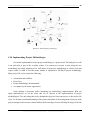
4.4. Project Methodology Overview
4.5. Background to Project Methodologies
4.6. CIPOC—A Conceptual Approach
4.7. Understanding Project Model Terminology
4.8. Methodology Design
4.9. Using the Mind-Mapping Concept
4.10. Implementing Project Methodologies
4.10.1. How to Get Started with Methodology
4.10.2. How to Implement the Methodology
4.10.3. How Long Is a Typical Implementation?
4.11. The use of Gantt Chart on Engineering Projects
5. Managing Power Electronics Project for IEEE Contest
5.1. Defining the entire Project – Making the Project
5.1.1. Supporting students to work in innovative way
5.1.2. Design of integrated drive as a practical application
5.1.3. Promotion of the faculty and the power engineering
5.1.4. Educational impact
5.2.
5.3.
5.4.
5.5.
5.6.
Breaking-down structure
Task description
Forming the team – Team Organization
Planning phase – Setting the Milestones
Running the Project: Progress – Control – Monitoring
School of Electrical Engineering – University of Belgrade
CONTENTS
62
62
63
65
66
67
69
70
72
72
73
74
76
77
79
80
81
86
87
88
88
89
90
93
95
95
96
96
97
97
101
104
105
109
4
PROJECT MANAGEMENT IN ENGINEERING
5.7. Documentation
5.8. Measured Progress - Required Progress Reports and
CONTENTS
110
111
Results
5.9.1.
5.9.2.
5.9.3.
5.9.4.
Progress in simulating and testing the drive
Progress in Hardware
Progress in Software
Progress in establishing safety regulations
6. Conclusions and Suggestions
APENDIX I
School of Electrical Engineering – University of Belgrade
112
117
122
128
133
135
5
PROJECT MANAGEMENT IN ENGINEERING
CONTENTS
6
Introduction
Each two years 4 basic IEEE 1sections in the field of Power Engineering make an open call for
Competition for all of the Universities throughout the world expecting the students to develop new
energy solutions through their work and innovation, but to be aware of manufacturability and practical
use of what they bring as a final prototype. Students World Contest: Future Energy Challenge
(http://www.energychallenge.org) is organized in order to bring innovations in the field of Energy
Science and to attract more and more students to think on the way of saving the energy.
Energy saving is a modern trend in electrical engineering, experiencing a great boom in last
decades. Reasons are constant rise of energy prices and awareness of limited energy resources on
Earth. Saving electrical energy is of outmost importance since it is the purest form of energy that can
be easily converted to any other form. According to some data, electrical drives in the developed
world consume between 60% and 70% of all the electric energy produced in these countries.
Electric motors impact almost every aspect of modern living. Refrigerators, vacuum cleaners,
air conditioners, fans, computer hard drives, automatic car windows, and multitudes of other
appliances and devices all use electric motors to convert electrical energy into useful mechanical
energy. In addition to running the common place appliances that we use every day, electric motors are
also responsible for a very large portion of industrial processes. Electric motors are used at some point
in the manufacturing process of nearly every conceivable product that is produced in modern factories.
Because of the unlimited number of applications for electric motors, it is not hard to imagine that there
are over 700 million motors of various sizes in operation across the world. This enormous number of
motors and motor drives has a significant impact on the world because of the amount of power they
consume.
1
Institute of Electrical and Electronics Engineers (IEEE) Power Electronics Society, Industry Applications Society,
Power Engineering Society, Industrial Electronics Society, European Power Electronics Association & National
Renewable Energy Laboratory
School of Electrical Engineering – University of Belgrade
PROJECT MANAGEMENT IN ENGINEERING
CONTENTS
7
Electric motor drive technology is constantly evolving and expanding to new applications.
More advanced electric motor drives are now replacing older motor drives to gain better performance,
efficiency, and precision. Advanced electric motor drives are capable of better precision because they
use more sophisticated microprocessor or DSP controllers to monitor and regulate motor output. They
also offer better efficiency by using more efficient converter topologies and more efficient electric
motors. The more advanced drives of today also offer a performance boost, by utilizing superior
switching schemes to provide more output power while using lighter motors and more compact
electronics.
Under the conditions of the challenge, our team has taken on the task of creating innovations in
motor that would provide the user with large cuts on operating cost through improved efficiency. The
purpose is to document future design innovations and their effect on overall efficiency. This is where
the 2005 International Future Energy Challenge comes into play.
A few years ago, project management in engineering was often an afterthought in assembling a
project team, and organizations turned to project managers only when their projects turned sour—as
they usually did. Today, project managers in Electrical engineering are in demand, and few
organizations would initiate projects without ensuring that they are managed.
Here, in my work, I will try to explain how important is the use of Project Management in
Electrical Engineering and I will show it on a practical example. I will try to demonstrate the way we
were running and managing one Project in power Electronics, showing step-by-step the progress of the
project, technical documentation and reports, gaining the final result – prototype.
Thesis is organized by following Chapters:
Chapter 1 – This Chapter explains the Fundamentals of Electrical Drives, speaking about
energy efficiency and electrical energy generation in coming years, as well as electric motors
consummation. Current motor technologies are presented here, with examples of control drives
topologies, especially the Digital Controlled AC Electrical Drive topology, which is the topic of the
Power Electronics Project. The technical goal of the Project was to construct adjustable speed motor
system costing less than US $40 (scaled on 1 million units production) for a 500 W unit, achieving
maximum efficiency and operating requirements while maintaining acceptable levels of performance,
reliability and safety. The purpose of using Digital Controlled AC Drives together with trends and
control techniques of AC Drives will show how great research in this field of Power Electronics can
make results in global energy savings. But, such great objectives need a serious Project planning.
These Electrical Engineering project are very complex because of necessity of Engineers from
School of Electrical Engineering – University of Belgrade
PROJECT MANAGEMENT IN ENGINEERING
CONTENTS
8
different field of research: Electronics, Powers, Automation, Software, Communication etc. Because
of the complexity it is very important to manage and lead the project properly, carrying about project
structure, time consummation, team members, tasks progress, technical documentation, in order to
produce desired result.
Chapter 2 – Typical Phases of the Project in Power Electronics are shown in the 2nd
chapter, that presents the logical steps need to be done in one project. Everything starts with an idea,
vision and mission. Choosing the right team members, the core of the project, members that will
understand and be obsessed with a project idea. Every project need to be carefully planed so, the
purpose of planning is to realize how much time, money, human recourses and finance are needed, so
the requirements, scope, and plan are important element of the Power Electronics project. If the project
is defined appropriately, the steps of Planning Phase will help make sure as well as schedule and costs
will. When the planning phase is over (and agreed), the "doing" phase begins, where establishing
control is main process. In Power Electronics projects, very important are testing and quality, this
means that no activity is completed until it has passed the (objectively) defined criteria which establish
its quality, and these are best defined (objectively) at the beginning as part of the planning.
Chapter 3 – This chapter presents The Project Managers’ and Team Leaders’ role in a
Power Electronics Projects. The manger of a small team has three major roles to play: to be a
planner, provider and a protector, but also to take a long-term view. He/she has access to information
and materials which the team needs; but also an experience in managing the project in power
Electronics, which means the optimum number of steps in simulations, testing, program coding etc…
Manager is a person who will define a problem and offer several solutions by his/her practical
experience. It is about motivation, setting the targets - and in selecting these targets, making a dramatic
effect upon team's sense of achievement. On the other hand, leadership is a way of focusing and
motivating group of engineers to achieve their aims – to do the project right. The chapter explains
leaders’ necessity to have a wide range of skills, techniques and strategies which include: Planning,
Communication skills, Organization and Awareness of the wider environment in which the team
operates, as well as project progress and technical documentation, which are most important. The
leader is a multicultural person, that develops own cultural sensitivity by observing and understanding
cultural differences.
Time Management is about controlling the use of most valuable (and undervalued) resource.
The managers’ role is to care about the deadlines and time consummation on the project, knowing the
complexity of the tasks and processes on the electrical engineering projects. It’s up to them to estimate
the time for different procedures like simulations, implementations, testing…
School of Electrical Engineering – University of Belgrade
PROJECT MANAGEMENT IN ENGINEERING
CONTENTS
9
On the other hand, it is about leaders to define the team, but teams are like relationships – so,
managers and leaders have to work at them. Team Leader’s role is implementing the Team Quality,
but also building Quality into the project.
Chapter 4 – The 4th Chapter is about purpose of Project Methodologies, where methodology
is a set of guidelines or principles hat can be tailored and applied to a specific situation. In a project
environment, these guidelines might be a list of things to do, especially in Electrical Engineering.
Strategy always comes before any tactics. It's similar to thinking before doing. The strategy
must be correct before we select a project or development methodology. By simply assessing those
project methodologies that exist today, it is obvious that a universal project approach simply won't
work. A project life cycle is, therefore, a collection of project phases, explained here.
It is essential that the management of any organization identify and articulate its critical
success factors (CSFs). These are the ground rules that determine the appropriateness of the
environment in which the organization operates. When trying to place any project life cycle or
methodology into perspective, it is always going back to the Client, Input, Process, Output, Clients
(CIPOC) approach.
The project manager's first task is to become familiar with the feasibility of the project. The
focus is how project methodologies can be developed to support projects in a team. Developing a
project methodology and adapting it to the situation often deal with changes on many levels—changes
in procedures, processes, and information systems. The one effective way to lay out the envisaged
framework of a project methodology is to illustrate or mind map it on paper first, thereby addressing
all areas of the organization.
Chapter 5 – This chapter explains the process of Managing Power Electronics Project for
IEEE Contest. It illustrates entire Power Electronics project with all project phases, done by
MiniDrive team consisted of 19 students from Laboratory of Digital Control of Electrical Drives,
University of Belgrade. The chapter explains in detail objective and vision, break-down structure, task
description, team organization of concrete Power Electronics project.
Special interest was given to technical documentation and progress reports because that help
leaders to control and monitor the whole project. Weekly reports examples are given, case studies, as
an instrument for choosing the right option in timeless situation, presentations of current results and
progress as well as way of combining the different results of one group to final project goal.
Because Students’ Contest organizers set up the milestones, which required three progress
reports for duration of the project, step-by-step activities are given, presenting easily how final Digital
Drive prototype is generated for 15 months of working.
School of Electrical Engineering – University of Belgrade
PROJECT MANAGEMENT IN ENGINEERING
CONTENTS
10
Activities like simulating, testing, code generating, components assembling, cost estimating,
analyzing, regulating the safety, are main for one Power Electronics project, and are separately showed
in this chapter, as well as results of these activities.
Chapter 6 – The final chapter called Conclusions and Suggestions presents the final
comments that can help in upgrading existing project and final prototype, but also it is need to know
that Project overruns are the norm. It is hard enough to keep a project on track in those disciplines
where the road has been traveled before, the activities are familiar, and the pitfalls are clearly marked.
Similarly, the project manager has to be all eyes and ears; he or she has to get the project back
on track when the project's integrity is threatened by the dysfunctions of the team, the institution, or
the technologies. A significant challenge to the project manager is to know when and how to intervene
but, for the most part, as they say, just "let them play."
.
.
.
School of Electrical Engineering – University of Belgrade
PROJECT MANAGEMENT IN ENGINEERING
ABOUT DIGITAL CONTROLLED AC ELECTRICAL DRIVES
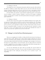
1. Electrical Drives Fundamentals
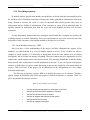
More than half of total electrical energy produced in developed countries is
converted into mechanical energy in electric motors. Among many types of the motors,
three-phase induction machines still enjoy the same unparalleled popularity as they did
centuries ago. At least 90% of industrial drive systems employ induction motors.
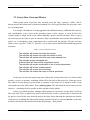
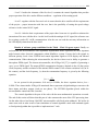
As environmental and other concerns slow the growth of electrical energy
generation in coming years, it becomes essential that we conserve and use this limited
and precious resource more efficiently. Conserving electricity and making it a better fuel
relies on the widespread adoption of the power conversion process, which takes
electricity from a source and converts it to a form exactly suited to the electrical load.
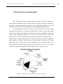
Electric motors consume more than 75% of all electrical power in the US. Adjustablespeed motors can improve the efficiency of these motors by about 50% in many
applications. They can also reduce costs considerably. Power electronics allows us to
develop efficient speed and torque control of electric motors at low costs. This, in turn,
calls for development of optimized electromechanical power conversion units.
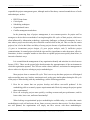
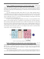
Picture 1.1: Residential motor energy use in 1995 (courtesy of NAECA).
School of Electrical Engineering – University of Belgrade
10
PROJECT MANAGEMENT IN ENGINEERING
ABOUT DIGITAL CONTROLLED AC ELECTRICAL DRIVES
The systems that controlled electric motors in the past suffered from very poor
performance and were very inefficient and expensive. In recent decades, the demand for
greater performance and precision in electric motors, combined with the development of
better solid state electronics and cheap microprocessors has led to the creation of modern
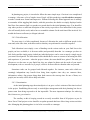
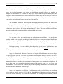
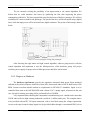
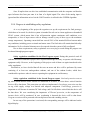
adjustable-speed drives. An adjustable speed drive is a system that includes an electric
motor as well as the system that drives and controls it. Any adjustable-speed drive can be
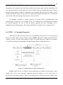
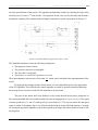
viewed as five separate parts: the power supply, the power electronic converter, the
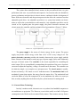
electric motor, the controller, and the mechanical load, presented on a Picture 1.2 below.
Picture 1.2: A typical adjustable-speed drive system.
The power supply is the source of electric energy for the system. The power
supply can provide electric energy in the form of AC or DC at any voltage level. The
power electronic converter provides the interface between the power supply and the
motor. Because of this interface, nearly any type of power supply can be used with nearly
any type of electric motor. The controller is the circuit responsible for controlling the
motor output. This is accomplished by manipulating the operation of the power electronic
converter to adjust the frequency, voltage, or current sent to the motor. The controller can
be relatively simple, or as complex as a microprocessor. The electric motor is usually,
but not necessarily, a DC motor or an AC induction motor. The mechanical load is the
mechanical system that requires the energy from the motor drive. The mechanical load
can be the blades of a fan, the compressor of an air conditioner, the rollers in a conveyor
belt, or nearly anything that can be driven by the cyclical motion of a rotating shaft.
1.1. Current Motor Technology
In today’s modern world, electronics are everywhere from handheld computers to
air conditioners to projection TVs. However, even in this world, over half of all power
consumption in the World can be accounted for by motors. These motors can vary from a
School of Electrical Engineering – University of Belgrade
11
PROJECT MANAGEMENT IN ENGINEERING
ABOUT DIGITAL CONTROLLED AC ELECTRICAL DRIVES
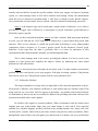
simple blender and fan motor to an industrial motor used for assembly lines in
automobile factories. When considering the mass power that the whole World consumes
in a year, it becomes apparent that if one can make these motors run even a couple tenths
of a percent more efficient, it can make a huge difference in power savings.
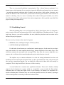
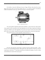
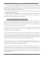
Picture 1.3: All parts of a typical electrical induction motor
Electric motors convert electrical energy into useful mechanical energy. This
energy can then be used to drive man household appliance, i.e., fans, compressors, etc.;
but, even in home applications not all motors are alike. Different types have varying
characteristics (and thus different efficiencies) making them suitable for certain situations
and not for others. Single speed induction motors are presently being used for most
residential applications ranging from portable fans to compressors commonly found in
refrigerators. These include both your single and three phase squirrel cage induction
motors. There is a noteworthy dissimilarity and a rather wide range of efficiency between
these single-speed induction motors. It is also worth mentioning that in general motor
efficiency comes at the price of horsepower and for this reason motor smaller motors are
generally less efficient. Universal AC/DC motors are commonly used for sporadic
applications where high speed is needed. Examples of this would be drills, food
processors, and vacuums. These are the “brush motors” (given its name for the set of
School of Electrical Engineering – University of Belgrade
12
PROJECT MANAGEMENT IN ENGINEERING
ABOUT DIGITAL CONTROLLED AC ELECTRICAL DRIVES
brushes that constantly change volt thus keeping the motor spinning in an attempt to align
polarity). The main problem with these types is significant losses associated with the
windings wear and tear on the brushes (most small motors fail due to worn brushes).
Induction motors include refrigerators and air conditioners but in many cases also
include washing machines. It is in this area that a greater efficiency would yield huge
return in he long run.
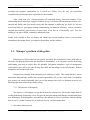
1.2. Digital Controlled AC Electrical Drives
Most of the motors are uncontrolled, but the share of adjustable speed induction
motor drives fed from power electronic converters is steadily increasing. It is estimated
that more than 50 billion dollars could be saved annually by replacing all “dumb” motors
with controlled ones. Three-phase induction motors are so common in industry that in
many plants no other type of electric machine can be found.
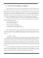
Asynchronous (AC) motors employ a simple but clever scheme of
electromechanical energy conversion. In the squirrel-cage motors, which constitute a vast
majority of induction machines, the rotor is inaccessible. No moving contacts are needed,
which arrangement greatly increases reliability of AC motors, permitting squirrel-cage
machines to be safely used in harsh environments, even in an explosive atmosphere. Also
these motors can run at high speeds and withstand heavy mechanical and electrical
overloads. In adjustable-speed drives (ACD), the low electric time constant speeds up the
dynamic response to control commands.
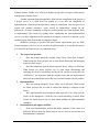
Picture 1.4: Digital Controlled Electric Drive System used as a water pump
School of Electrical Engineering – University of Belgrade
13
PROJECT MANAGEMENT IN ENGINEERING
ABOUT DIGITAL CONTROLLED AC ELECTRICAL DRIVES
Although operating principles of induction motors have remained unchanged,
significant technological progress has been made over the years, particularly in the last
few decades, bringing smaller, lighter, more reliable and more efficient motors to the
global market. Conservatively, the average life span of an induction motor can be
assumed to be about 12 years (although properly maintained standard motors can work
for decades).
An electric motor driving a mechanical load, directly or through a gearbox and the
associated control equipment such as power converters, switches, relays, sensors and
microprocessors, constitute an Digital Controlled Electric Drive System. It should be
stressed that, as of today, most induction motors drives are still basically uncontrolled,
the control functions limited to switching the motor on and off. In applications where the
speed, position or torque must be controlled, ASDs with a dc motors are still common.
However, ASDs with induction motors have increasing popularity in industrial
practice. The progress in control means and methods for these motors, particularly
spectacular in the last decades, has resulted in development of several classes of ac ACDs
having a clear competitive edge over the dc drives.
1.3. A Purpose and use of Digital Controlled AC Electrical Drive
Most of the energy consumed in industry by induction motors can be traced to
high-powered but relatively unsophisticated machinery such as pumps, fans, blowers,
grinders or compressors. Clearly, there is no need for high dynamic performance of these
drives, but speed control can bring significant energy savings in most cases. For example,
a constant-speed blower, whose output is regulated by choking the air flow in a valve, so
the same valve could be kept fully open at all times if the blower were part of an
adjustable-speed drive system. At a low air output, the motor would consume less power
than that in the uncontrolled case, thanks to the reduced speed and torque.
High-performance induction motor drives, such as those for machine tools or
elevators, in which the precise torque and position control is a must, are still relatively
rare, although many sophisticated control techniques have already reached the stage
particularly. For better drive ability, high-performance adjustable-speed drives are also
increasingly used in electrical traction and other electrical vehicles.
Except for simple two-, three- or four-speed schemes based on pole changing, an
induction motor ASD must include a variable-frequency source, the so-called inverter.
School of Electrical Engineering – University of Belgrade
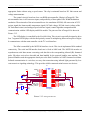
14
PROJECT MANAGEMENT IN ENGINEERING
ABOUT DIGITAL CONTROLLED AC ELECTRICAL DRIVES
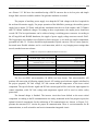
Inverters are dc to ac converters, for which the dc power must be supplied by a rectifier
fed from the ac power line. The so-called dc link, in the form of capacitor or reactor
placed between the rectifier and inverter, gives the rectifier properties of a voltage source
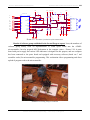
or a current source (presented in Picture 1.5).
Picture 1.5: Electrical circuit for 500W AC induction motor drive
Because rectifiers draw distorted, no sinusoidal currents from the power system,
passive or active filters are required at their input to reduce the low-frequency harmonic
content in the supply currents. Inverters, in the other hand, generate high-frequency
current noise, which must not be allowed to reach the system. Otherwise, operation of
sensitive communication and control equipment could be disturbed by the resultant
electromagnetic interference (EMI). Thus, effective EMI filters are needed too.
For control of ACDs, microcomputers, microcontrollers and digital signal
processors (DSPs) are widely used. When sensors of voltage, current, speed or position
are added, an ASD represents a much more complex and expensive proposition that does
an uncontrolled motor. This is one reason why plant managers are so often wary of
installing ASDs. On the other hand, the motion-control industry has been developing
increasingly efficient, reliable an user-friendly systems, and in the time to come ASDs
with induction motors will certainly gain a substantial share of industrial applications.
School of Electrical Engineering – University of Belgrade
15
PROJECT MANAGEMENT IN ENGINEERING
ABOUT DIGITAL CONTROLLED AC ELECTRICAL DRIVES
1.4. Trends in AC Electrical Drives
Physical size and weight provide the most visible evidence of the remarkable
evolution of ac variable-frequency drives (VFDs) in the past 50 years. However, what's
under the skin is even more dramatic for the performance, efficiency, and reliability now
delivered by these motor controls. Making it all happen were advances in powerswitching transistors, microprocessors, other hardware, plus software functions that ease
users' concerns for drive application and maintenance.
Picture 1.6: Industrial Variable-frequency converter
Practical industrial variable-frequency drives (VFDs) emerged in the late 1950s,
with automation of synthetic-fiber processes being one early application. But, ac drive
developments started in 1965. Its first high-speed, rack-style industrial VFD was in
production in 1968. It allowed induction grinder motors to operate up to 180,000 rpm.
Adoption by heavier industry followed considerably later in the 1970s. Early ac drives
operated in open loop and had limited performance. Developments in VFD controls in the
next decade or so, coming from hardware and software, these ac drives to challenge the
supremacy of dc adjustable-speed drives.
School of Electrical Engineering – University of Belgrade
16
PROJECT MANAGEMENT IN ENGINEERING
ABOUT DIGITAL CONTROLLED AC ELECTRICAL DRIVES
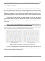
1.4.1. Control Techniques.
Following earlier R&D, first industrial installations of Pulse Width Modulation
PWM drives took place in the '70s. Paper mills and subways set the basis for significant
product advancement and robustness. After technology had proved its reliability and
competitiveness on these demanding applications, ac drives were accepted as leading
control technology, starting to replace dc drives.
The high accuracy and fast dynamic control in today’s ac drives was enabled by
the “advent of small, relatively inexpensive microprocessors and other high-density
digital circuitry.” The importance of power transistors to advancing ac drives is because
IGBTs allow fairly low loss switching at rates as high as 16 kHz, permitting pulse-width
modulated (PWM) drive output that results in a near-sinusoidal current in an ac motor.
Besides delivering dynamic motor torque control, PWM technology allows use of higher
carrier frequencies for power switching to reduce audible noise in applications requiring a
low noise environment. Another significant feature of today’s drives is ability to be
configured to act as a bidirectional ac-to-dc power converter, which allows the flow of
low-harmonic-content power either into or, by regeneration, away from a drive system.
Early ac drives operated in open loop control but had limited performance. A
major step forward was development of field-oriented (flux vector) control for induction
motors by Siemens in 1971—followed by others—which eventually pushed VFDs to
meet or exceed dc drive performance in many applications. Sensorless-vector control
(eliminating a shaft encoder) and other drive algorithm advances followed. And the
evolution is accelerating.
Early ac drives (1980s) employed multiple transistors per phase due to their
limited voltage and current ratings. This has changed to all-in-one packages, so that a
10kW drive today has a structure smaller than one transistor pack of the vintage drive.
New generations of transistors continue to be improved as manufacturers develop smaller
and more efficient power devices, insulated-gate bipolar transistors (IGBTs) remain
present-day workhorse power devices.
Picture 1.7: IRAMS – IGBTs module
School of Electrical Engineering – University of Belgrade
17
PROJECT MANAGEMENT IN ENGINEERING
ABOUT DIGITAL CONTROLLED AC ELECTRICAL DRIVES
Flux-vector (field-oriented) control, sensorless-vector control, and newer designs
like three-level topology, matrix converter (see main article), and other approaches yet to
come should continue to propel the evolution of VFDs. (By the way, “sensorless-vector
control” is one of our industry’s misnomers. Encoderless-vector control is a more exact
naming, as the term refers to motor control without using a shaft-mounted encoder or
feedback device. However, motor parameters, such as voltage, current, and others are
measured or “sensed,” as input to the drive’s dynamic controls.)
1.4.2. Use of Microprocessor.
On the control side, analog was firstly used, giving way to digital control, though
initially based on integrated circuits. Microprocessor (MPU)-based digital drives came
somewhat later, and at first offered only open-loop (V/Hz) control. Continuing advances
in MPUs allowed adding multiple control types in the same drive, with only software
parameter changes needed to switch control mode.
Picture 1.8: ATMEL microprocessor used for digital control of Electrical Drive Systems
Flexibility, intelligence, and user friendliness are state-of the art VFD features.
Flexibility means satisfying numerous applications with one drive type that offers simple
open-loop, closed-loop, flux vector, and even near-servo control. This capability lowers
the drive's cost of ownership by reducing on-site inventory, operator training, and
replacement part costs. MPUs and advanced diagnostic capabilities allow users to access
intelligence built into a drive, thus lowering commissioning cost and downtime. Soft
functions, like Automatic Motor Adaptation and software wizards, remove uncertainty in
setting-up a drive/motor combination. 'User-friendly evolution' of the operator interface
into software functions also shortens set-up to reduce potential operator error and
simplify interaction with the drive.
Multiple control modes mean state-of-the-art in VFDs. Low-end drives typically
offer V/Hz and sensorless-vector control, while higher-end drives originally with fluxvector control later added other control modes. V/Hz operation enables control of
multiple motors from one drive. One drive type for different applications also helps
School of Electrical Engineering – University of Belgrade
18
PROJECT MANAGEMENT IN ENGINEERING
ABOUT DIGITAL CONTROLLED AC ELECTRICAL DRIVES
reduce spare parts inventory. Connectivity is another core VFD feature today, so
networked applications now amount to about 50% of all drives—and increases with
higher-end units.
In mid 90’ DTC as an advanced technology, able to control motor torque and
speed directly without need for separate control of voltage and frequency. Extremely fast
torque-response time and accuracy are claimed, 'typically 10 times faster than with
PWM.' DTC also is said to optimize motor flux, which improves combined energy
efficiency of motor and drive. DTC does not use a modulator and works without motor
shaft position or speed feedback. With DTC, 100% torque is available at zero speed and
small torque increments can be controlled at low frequencies in less than 1 millisecond
1.4.3. Integrate external functions.
Future VFDs will accelerate integration of various external functions into the
drive package. PLC and motion control functionality can now be implemented in a drive
at a much lower total system cost. For the most-sophisticated systems application, much
of logic and motion control still must be handled by peripheral electronics, but it’s
expected to change rapidly. Future drive systems will be composed entirely of enclosures
filled with drive units, power wiring and limiting devices, serial communications wiring,
and human-machine display and interface devices.
ABB mentions rising environmental concerns and higher energy costs affecting
future ac drives. They're destined for wider usage in all industries and developing
markets, raising the number of motors under variable-speed control from as low as 5%
worldwide, according to ABB. Also noted is continuing shrinkage of drive size, even as
more miniature features are added. Future VFDs will see new, non-traditional
applications—replacing other types of control (or adding first-time automation).
Future VFDs will participate more in 'green technology' developments, especially
with higher energy costs and regional electricity shortages possible. Efficiency and
conservation are obvious desired benefits, but lower operating costs, higher reliability,
and still more compact drive designs are other promises. Research on new control
topologies continues in industry and academia, while newer, existing controls—such as
three-level topology and matrix converter—will find expanded application ahead.
Benefits of three-level topology include lower surge voltage at the motor, lower
leakage current, and improved thermal management at low speeds. Even newer matrix
converter looms especially attractive, as it offers enhanced regeneration capabilities for
School of Electrical Engineering – University of Belgrade
19
PROJECT MANAGEMENT IN ENGINEERING
ABOUT DIGITAL CONTROLLED AC ELECTRICAL DRIVES
VFDs and eliminates capacitors in the dc bus. Commercial release of matrix converter is
on plan for 2005 for regenerative applications.
1.4.4. Yet to come
Looking a decade ahead, ABB sees VFDs getting still smarter. An extension of
assisted startup will allow set-up of smart drives with minimal intervention from the user.
Also, a chip embedded in the motor could automate motor identification upon drive
startup.Tighter integration with control systems also lies in the future of VFDs. ABB
differentiates between numerous existing 'connections' for drives and real integration that
is just starting. Such real integration fully involves the drive in the programming and
configuration environment of the control system. This capability will work into lowerpriced products, coming down from the high-end as a natural migration of drive features.
Danfoss sees growing adoption of distributed drive systems in industry. Fueling
the trend are lower-cost, higher-reliability drives that can be located next to [or on] the
motor—decreasing installation costs without long motor/drive cable sets and associated
conduit trays. In addition, distributed drives have the advantage of minimizing EMC
problems arising from long motor cables, reducing the need for costly filters. Distributed
systems also will grow from more integration of motion control and PLC functionality
into VFDs.
Other developments include greater use of Ethernet-compatible communication
to link application information of drives into plant wide networks and wireless access to
drives, especially ones in difficult locations, because ethernet represents the best
opportunity for achieving an industry-standard communication system.
Meanwhile, engineers from Bosch think that today's optional drive features will
become future necessities. They cite high starting torque, closed-loop speed and torque
control, preventive maintenance, and direct data link to manufacturing control systems as
prime examples. Other upcoming advances mentioned are:
• Active drive front-end (including harmonic limitation) slowly gaining acceptance
as energy costs and grid standards increase; and
• Simple speed actuators evolving to a scalable, distributed, field-level
machine/process control unit with PLC or process capability.
School of Electrical Engineering – University of Belgrade
20
PROJECT MANAGEMENT IN ENGINEERING
ABOUT DIGITAL CONTROLLED AC ELECTRICAL DRIVES
1.5. Developing New Technology - IEEE Future Energy Challenge
Energy saving is a modern trend in electrical engineering, experiencing a great
boom in the last decades. Reasons are constant rise of energy prices and awareness of
limited energy resources on Earth. The picture 1.6. presents the prediction of energy
resources up to year 2200.
Picture 1.9: Energy resources, coal, oil, gas, uranium respectively
Saving electrical energy is of outmost importance since it is the purest form of
energy that can be easily converted to any other form. According to some data, electrical
drives in the developed world consume between 60% and 70% of all the electric energy
produced in these countries. Some of these motors are in houses of each one of us, in our
blenders, vacuum cleaners, washing machines, air-conditioners and usually we pass by
them without even noticing them. Everyone household has at least one these appliances,
so just imagine what amount of energy they consume and what amount of money as well.
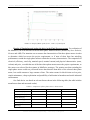
Frost&Sullivan Market Intelligence report that motors with power under 7,5 kW
present 40% of USA market, those of powers of 7.5kW to 75kW represent 31% and those
over 75kW are 29% of the market. The next well-known fact is that over 90% of all the
motors produced in the USA have less than one horse power and overall value of this
market share is more than 7 billion US dollars annually.
Due to these facts several IEEE Societies decided to organize a biannual Students
Contest in order to encourage development of new technologies and to bring dramatic
improvements to low-cost single-phase motor systems for home use. Young engineers
need to realize the motor system drive, to incorporate practicality, manufacturability, and
School of Electrical Engineering – University of Belgrade
21
PROJECT MANAGEMENT IN ENGINEERING
ABOUT DIGITAL CONTROLLED AC ELECTRICAL DRIVES
affordability into competition process. But also the aim of the contest was to improve
education through development of innovative team-based solutions to complex problems.
Following the market trends in Electrical Engineering the objective of this contest
was to construct adjustable speed motor drive system that costing less than US $40,
scaled in 1 million pieces production, for a 500 W unit. The desired motor drive system
have to achieve maximum efficiency and operating requirements, but to maintain
acceptable levels of performance, reliability, and safety.
1.6. Complexity of Projects in Power Electronics
The requirements of the Power Electronics Projects are always the same: more
efficiency, less expanses and consumption, higher level of communication with other
electrical devices, bigger working autonomy of devices etc. Running the project of
generating one Power Electronics device, from the beginning to the functional prototype,
is not easy at all. It is a process that can take several months long, sometimes years, and it
takes lots of practical research approaches with the same objective.
Projects in Power Electronics need several different types of engineers to work on
in order to generate digital drive system with certain requirements. Due to the fact,
projects dealing with Power Electronics are very complex, where a variety of engineers
from department of Electronics, Powers, Automation, Communication, Software design
are required. It is necessary to involve all of them because of ideas needed for innovative
work, sometimes because of specific point of view in breaking situations, but mostly
because the final drive system is consists of plenty small electrical details, so all
engineering disciplines are more than necessary.
So, because of plenty of different engineers, it is important to have one (or two)
project leaders who will be responsible for people, equipment, support services,
deadlines, budget etc. Their responsibility is very big because they need to make the
Project structure, delegate work and responsibility to the team members, build a
functional communication among team members together with working atmosphere.
Communication skills and team coordination of the manager/leader in Power
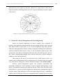
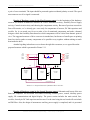
Electronics Project are highly required. If gaining the same idea, project members will do
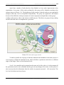
same efforts on different activities. All members of the project in Electrical Engineering
have to answer clearly on questions presented in Picture 1.7, showing that they
School of Electrical Engineering – University of Belgrade
22
PROJECT MANAGEMENT IN ENGINEERING
ABOUT DIGITAL CONTROLLED AC ELECTRICAL DRIVES
understand the project objectives and aims. When find a proper answers, there are no
doubts the members will bring the success as it is expected from them in each of aspects
of the project.
Picture 1.10: Some questions that are asking to all project members at the beginning
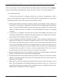
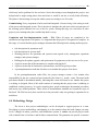
1.7. The need for a Project Management in Electrical Engineering
Projects in electrical engineering are always complex with a multitude of
variables. Most application implementations cut across multiple business units, each with
their unique business requirements. A new or altered application must often interface
with many other applications, thereby creating an integration challenge that is difficult to
estimate in both time and resources. Worse yet, the downstream impact to these other
systems may cause adverse consequences that may not be felt until long after "go live"
day. Further, assigning and managing scarce resources often cause a project manager to
rethink his or her chosen profession.
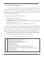
Who among us has never been associated with a failed project? Some very
extensive and well-documented surveys indicate that 84% of projects either fail outright
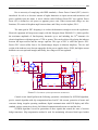
or are delivered late. The project is like the "Bermuda Triangle": cost, schedule, quality.
Effective project management begins with executive commitment and
sponsorship. Without the "chief" declaring a sense of urgency and importance to the
project, it is doomed to dismal results right from the start. What will be described in this
master thesis is a systemic, methodical approach to making project management a part of
everyday culture. When all projects in Electrical engineering field follow a standardized
template, then and only then will project management evolve gradually into an everyday
School of Electrical Engineering – University of Belgrade
23
PROJECT MANAGEMENT IN ENGINEERING
ABOUT DIGITAL CONTROLLED AC ELECTRICAL DRIVES
way of life. When an organization's maturity reaches a repeatable model, management of
projects becomes an institutionalized process. Hence, results become predictable.
Therefore, all three corners of the Bermuda Triangle can be achieved on every project.
cost
PROJECT
schedule
quality
Picture 1.11: Project Management's "Bermuda Triangle"
Here in my master thesis I will try to present how one International project was
led using Project Management. That is the project which took part on Students' World
Contest: "Future Energy Challenge 2005" - www.energychallenge.org , organized by four
IEEE Societies. Laboratory of Digital Control of Electrical drives with its 20 students
made a prototype motor system for wide range of applications (residential and industrial).
This work presents the team organization, schedules, schemes, time, financial structure,
in order to show what principles were used to make a final product – digital motor
prototype.
Using this work, anyone from field of Electrical Engineering will be able to lead
project and will spend much less energy and efforts, guided by our experience and
results. Thesis is covered by theory of Project Management, and also examples are given
from the IEEE project.
School of Electrical Engineering – University of Belgrade
24
PROJECT MANAGEMENT IN ENGINEERING
TYPICAL PHASES OF THE PROJECT IN POWER ELECTRONICS
25
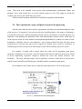
2. Typical Phases of Power Electronics Projects
Miyamoto Musashi,
a seventeenth-century samurai:
One can win with the long sword,
and one can win with the short sword as
well. For this reason, the precise size of
the sword is not fixed. The way of my
school is the spirit of gaining victory by
any means.
2.1. Projects in Electrical Engineering
A Project is a temporary endeavor undertaken to create a unique product or service.
•
•
Temporary: every project has a definite start and end that finishes with a final product
Unique: every project is different in some distinguishing way, unique final product
Project is a temporary effort of work, a one-time event that meets the following criteria:
• Has a start and an end date.
• Has schedule, cost, and quality constraints.
• Is a unique endeavor and contains risk.
• Has a certain scope that needs to occur.
Almost any human activity that involves carrying out a non-repetitive task can be a project. But
there is a big difference between carrying out a very simple project involving one or two people and
one involving a complex mix of people, organizations and tasks. This has been true for millennia, but
large-scale projects like the Pyramids often used rather simple control and resource techniques
including brute force to 'motivate' the workforce!
In essence a project in electrical engineering can be captured on paper with a few simple
elements: a start date, an end date, the tasks that have to be carried out and when they should be
finished, dependencies among the activities and some idea of the resources (engineers, computer tools,
technical ewuipement, etc) that will be needed during the course of the project. When the plan starts to
involve different things happening at different times, some of which are dependent on each other, plus
resources required at different times and in different quantities and perhaps working at different rates,
the paper plan could start to cover a vast area and be unreadable.
School of Electrical Engineering – University of Belgrade
PROJECT MANAGEMENT IN ENGINEERING
TYPICAL PHASES OF THE PROJECT IN POWER ELECTRONICS
26
2.2. Project Idea, Vision and Mission
When people speak of projects, they normally mean the large, expensive, visible, cast-ofdozens projects that characterize systems development. Few will argue that these do not require some
level of management.
For example, the hardware is being upgraded with additional memory, additional disk capacity,
and, coincidentally, a new version of the operating system. Is this a project, or can it be left to the
systems people to simply do the work without imposing a project structure on them? There is a gray
area between activities that are part of someone’s daily responsibilities and activities that constitute a
project. As a consequence, many organizations have wrestled with the question “How do we know
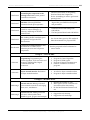
when we have a project?” Table 2.1. provides a set of criteria and a checklist that should help provide
an answer.
Table 2.1: Project Definition Criteria
The activities will involve more than two people.
The activities will require more than two weeks of effort.
The activities will require more than one month elapsed time.
The activities involve substantial risk.
If the activities fail, there will be a significant impact.
The activities will require coordination of two or more departments.
The activities will involve outside partners.
The activities will involve new technology.
The activities fall outside the scope of normal operations.
Each project in electrical engineering starts with an idea, mission and vision. It is mostly a final
product, a service, an outcome, something which will be the result of the project. So, when one gets an
idea what to develop during a project (what is a purpose of the project), it is helpful to make a steps
which guide one to the final product. That is planning phase. The idea should be tied to some real-time
objective – something which is possible to make and place on the market.
Firstly it is needed to make a concept of final product, it is necessary to know how it will look
like at the end. That is a vision of the project and the Project Leader is a person that is obsessed with
the project vision. He/she cares about the project direction, always knowing the right direction. But the
whole process of making the final product starting from the first idea is a project mission, so the team
members care that the idea should convert into the prototype – final product.
School of Electrical Engineering – University of Belgrade
PROJECT MANAGEMENT IN ENGINEERING
TYPICAL PHASES OF THE PROJECT IN POWER ELECTRONICS
27
2.3. Forming the right team of engineers
Before much progress can be made, a core team needs to be formed. The team will investigate
the idea further, determine the requirements, decide how to approach the implementation, and set the
detailed costs and schedule. Identifying core team members is very tough job. They have to be persons
that will be directly responsible for the project progress. They must be aware of the responsibility they
have, as a core of the whole organization. Each of them have to be responsible for each section in one
project, they will be head of departments that will together bring the technical innovations to the
product.
Projects can be divided into teams or sub-teams (groups) that are small enough to foster
effective communication. Cross-functional communication between engineering, testing,
manufacturing, assembling, servicing, etc. is very important. Power Electronics projects are pretty
complex because of lots of different engineers working together on the same mission. They are divided
into groups with strict goals, objectives and results.
To accomplish the project goals, it is necessary to assemble the right Team and Leader. To
select one empowered “mad person-on-a-mission” who will be the leader of the project. The leader has
to believe in the project and be ready to drive it forward! It is technically experienced person, have
done on several similar projects before and can recognize the right way to find solution when needed.
We use the term “project leader” to emphasize how important it is to exert leadership, not just
managing a set of tasks. The Project Leader ensures that the Concept/Planning phase results in a project
supported by a sound business case for the company. He leads the team in developing the project
definition; getting the right team members involved, etc.
It’s important to realize that leadership is called for in many different situations. One may not
be the overall project leader, but might be the leader of a technical sub-team. In that case one’s main
objective is to lead own sub team to a sound design that meets the already streaked defined
requirements.
The job of the leader has three key components:
•
Leading the overall effort (“Obsessed” Leader)
•
Dealing with individuals - working with team members, understanding styles,
communication and listening, motivating and rewarding, managing and resolving
conflicts etc.
•
Managing the work - planning, delegating, tracking…
And there are people outside your company who should be considered part of the team!
Vendors, customers, contractors are all influencing the outcome of the project, contributing to the
School of Electrical Engineering – University of Belgrade
PROJECT MANAGEMENT IN ENGINEERING
TYPICAL PHASES OF THE PROJECT IN POWER ELECTRONICS
28
work. They need to be included in the project team communication, requirements efforts, and
planning. Every team should strive to involve outside experts as well. They might be outside the
company; they may be just outside the project team.
All these outside members should also be considered as potential team members.
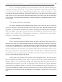
2.4. The requirements, scope, and plan of projects in engineering
After the idea come the more specific requirements, assessing risk, and determining the scope
of the project we’ll commit to. Every project need to be carefully planed so, the purpose of planning is
to realize how much time, technical equipment, human recourses and finance are needed. But also very
important is that planning the production starts with understanding customer needs, which helps to
create a project vision. It is also needed to investigate design alternatives, evaluate cost, make a workbreakdowns, schedules, risks for each alternative. Also, making tradeoff decisions and agree upon
requirements are activities that must not be forgotten. In general, plan is done by experience, or
estimating process due to the previous similar projects with similar elements, processes, results…
For example, if started with a project where the result will be generating some power
electronics components it is necessary to involve engineers that already worked on the projects in field
of Power engineering, experience enough to estimate the costs, time, human resources, risk,
feasibility… The scope and plan require lots of experience, because of that most of projects have
outside experts from different fields that give feasibility studies to estimate requirements.
We need data in each of these areas to make decisions about what we’ll do on this project.
Picture 2.1. Goals balanced in the planning phase
School of Electrical Engineering – University of Belgrade
PROJECT MANAGEMENT IN ENGINEERING
TYPICAL PHASES OF THE PROJECT IN POWER ELECTRONICS
29
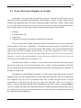
2.5. The schedules and costs
When all requirements are took into consideration, next step is to make a detailed workbreakdowns, to finished a schedules, budgets for each activity and a total budget, so that management
upon the project can be performed easily. It is needed to execute the Concept/Planning phase of the
project in such a way that the original idea is developed into a product or service concept as a technical
innovation with a certain value on the market.
The steps of Planning Phase will help make sure the project is defined appropriately. It is
important not to forget any step of the project, because later-one the costs can only increase, but the
time will be only shorter. The final schedule will give a number of activities, so they need to be divided
onto small details in order to be properly estimated. Each activity need to be defined by: time needed,
costs and number of engineers working on, like presented in the Table 2.2.
Table 2.2: Example of activity Definition
Activity
Time
required
Costs
Human
resources
1.
Assembling the circuit board
15 days
120 €
2 electronic
engineers
2.
Choose the components for
circuit board
20 days
250 €
4 electronic
engineers
2.6. Questions to Ask at the Start of a Power Electronics Project
So how do we ensure that we define a project that will benefit the requirements and expectations,
and how do project members go about answering these questions about the “project idea”?
After making the outlines of the project, creating the schedules and costs, it is expected to start with
asking questions which will help to remove the doubts should or should not start with the project. If
one can give direct answers to all asked questions, he/she is committed to start with project. So, what
kind of questions should be asked:
What does the customer need, market orientation?
What problem are customers trying to solve?
What features are most important?
When do customers need it?
School of Electrical Engineering – University of Belgrade
PROJECT MANAGEMENT IN ENGINEERING
TYPICAL PHASES OF THE PROJECT IN POWER ELECTRONICS
30
2.7. Starting with specification
A specification is the definition of the project: a statement of the problem, not the solution.
Normally, the specification contains errors, ambiguities, misunderstandings. The work on the
specification can seen as the first stage of Quality Assurance since you are looking for and countering
problems in the very foundation of the project - from this perspective the creation of the specification
clearly merits a large investment of time.
The agreement upon a written specification has several benefits:
•
•
•
•
the clarity will reveal misunderstandings
the completeness will remove contradictory assumptions
the rigour of the analysis will expose technical and practical details which numbties normally
gloss over through ignorance or fear
the agreement forces all concerned to actually read and think about the details
From a purely defensive point of view, the agreed specification also affords protection against the
one who have second thoughts, or new ideas, half way through the project. Once the project is
underway, changes cost time (and money). The existence of a demonstrably-agreed specification
enables to resist or to charge for (possibly in terms of extra time) such changes. Further, people tend to
forget what they originally thought; you may need proof that you have been working as instructed.
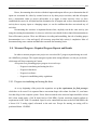
In power electronics projects most specifications show the desired direction of the final product,
so specification is making kind of a shape for final product, as presented in Table 2.3.
Table 2.2: Example of Design specification for one Power Electronics Project
1
2
3
4
5
6
7
8
9
10
11
12
13
14
Single-phase source
Motor mount compatibility – NEMA #48 Frame Size
Coupling dimensions – see specifications
Maximum input current 150% of full load current
Efficiency > 70% @ 1500 rpm (150-5000 rpm, 50W – 500W)
PF > 80% @ 1500 rpm, 500 W
IEC 320 input connection
Electrical noise – FCC Class A
Acoustic noise – Less than 50 dBA sound level measured 0.5 m from the unit
Self-protect against continuous stall, over temperature, or loss of input source
Environment – Ambient -20C to +40C; suitable for indoor or outdoor domestic applications.
10 years maintenance free
< 8 kg for complete system
Metal casing must be connected to safety ground
School of Electrical Engineering – University of Belgrade
PROJECT MANAGEMENT IN ENGINEERING
TYPICAL PHASES OF THE PROJECT IN POWER ELECTRONICS
31
2. 8. Providing structure
If decided what the specification intends, next problem is to decide what the team actually need to
do, and how to do it. Providing some form of framework, both to plan and to communicate what needs
doing. Without a structure, the work is a series of unrelated tasks which provides little sense of
achievement and no feeling of advancement. If the team has no grasp of how individual tasks fit
together towards an understood goal, then the work will seem pointless and they will feel only
frustration.
To take the planning forward, therefore, turning the specification into a complete set of tasks with
a linking structure is needed. Fortunately, these two requirements are met at the same time since the
derivation of such a structure is the simplest method of arriving at a list of tasks.
2.8.1. Work Breakdown Structure - WBS
Once you have a clear understanding of the project, and have eliminated the vagaries of the
numbties, you then describe it as a set of simpler separate activities. If any of these are still too
complex to easily organize, it is necessary to break them down also into another level of simpler
descriptions, and so on until can manage everything. Thus one complex project is organized as a set of
simple tasks which together achieve the desired result. The reasoning behind this is that the human
brain can only take in and process so much information at one time. To get a real grasp of the project,
one have to think about it in pieces rather than trying to process the complexity of its entire details all
at once. Thus each level of the project can be understood as the amalgamation of a few simply
described smaller units.
The first step in preparing a project WBS is to identify the major sets of activities. Consider a
typical systems development project that also requires selection of hardware or software. Table 2.4.
gives one possible list of major activities.
Table 2.4: Typical Major Activity Groups
Activities that provide management, coordination, and control
Activities to select and acquire hardware or software
Activities to build and unit test the system
Activities to integrate and systems test the system
Activities that involve the users
Activities to implement the system
School of Electrical Engineering – University of Belgrade
PROJECT MANAGEMENT IN ENGINEERING
TYPICAL PHASES OF THE PROJECT IN POWER ELECTRONICS
32
In planning any project, it is needed to follow the same simple steps: if an item is too complicated
to manage, it becomes a list of simpler items. People call this producing a work breakdown structure
to make it sound more formal and impressive. Without following this formal approach one is unlikely
to remember all the niggling little details; with this procedure, the details are simply displayed on the
final lists. One common fault is to produce too much detail at the initial planning stage. You should be
stop when you have a sufficient description of the activity to provide a clear instruction for the person
who will actually do the work, and to have a reasonable estimate for the total time/effort involved. It is
needed the former to allocate (or delegate) the task.
2.8.2. Task Allocation
The next stage is a little complicated, because of allocation the tasks to different people in the
team and, at the same time, order these tasks so that they are performed in a sensible sequence.
Task allocation is not simply a case of handing out the various tasks on your final lists to the
people you have available; it is far more subtle (and powerful) than that. As a manager you have to
look far beyond the single project; indeed any individual project can be seen as merely a single step in
your team's development. The allocation of tasks should thus be seen as a means of increasing the skills
and experience of your team - when the project is done, the team should have gained. The tasks you
allocate are not the ones on your finals lists, they are adapted to better suit the needs of your team's
development; tasks are mounded to fit people, which is far more effective than the other way around.
Sometimes tasks can be grouped and allocated together. For instance, some tasks which are
seemingly independent may benefit from being done together since they use common ideas,
information, talents. One person doing them both removes the start-up time for one of them; two
people (one on each) will be able to help each other.
2.8.3. Guesstimation
At the initial planning stage the main objective is to get a realistic estimate of the time involved
in the project. Establishing this not only to assist higher management with their planning, but also to
protect team from being expected to do the impossible. The most important technique for achieving
this is known as: guesstimation.
The corollary to this is keeping records in an easily accessible form of all projects as you do
them. Part of final project review should be to update personal data base of how long various activities
take. Managing this planning phase is vital to be successful as a manager.
School of Electrical Engineering – University of Belgrade
PROJECT MANAGEMENT IN ENGINEERING
TYPICAL PHASES OF THE PROJECT IN POWER ELECTRONICS
33
There are two practical problems in guesstimation. First, is about being too optimistic. It is
human nature at the beginning of a new project to ignore the difficulties and assume best case scenario
- in producing estimates (and using those of others) one must inject a little realism. In practice, one
should also build-in a little slack to allow yourself some tolerance against mistakes. This is known as
defensive scheduling. Also, in a case of eventually deliver ahead of the agreed schedule, one will be
loved. Second, one will be under pressure from senior management to deliver quickly, especially if the
project is being sold competitively.
2.9. Establishing Control
When the planning phase is over (and agreed), the "doing" phase begins. Once it is in motion, a
project acquires a direction and momentum which is totally independent of anything predicted. To gain
some hope, however, you need to establish at the start (within the plan) the means to monitor and to
influence the project's progress.
There are two key elements to the control of a project
•
•
milestones (clear, unambiguous targets of what, by when)
established means of communication
For the leader, the milestones are a mechanism to monitor progress; for the team, they are shortterm goals which are far more tangible than the foggy, distant completion of the entire project. The
milestones maintain the momentum and encourage effort; they allow the team to judge their own
progress and to celebrate achievement throughout the project rather than just at its end.
The simplest way to construct milestones is to take the timing information from the work
breakdown structure and sequence diagram. When you have guesstimated how long each sub-task will
take and have strung them together, you can identify by when each of these tasks will actually be
completed. This is simple and effective; however, it lacks creativity.
A second method is to construct more significant milestones. These can be found by identify
stages in the development of a project which are recognizable as steps towards the final product.
Sometimes these are simply the higher levels of your structure; for instance, the completion of a
market-evaluation phase. Sometimes, they cut across many parallel activities; for instance, a prototype
of the eventual product or a mock-up of the new brochure format.
School of Electrical Engineering – University of Belgrade
PROJECT MANAGEMENT IN ENGINEERING
TYPICAL PHASES OF THE PROJECT IN POWER ELECTRONICS
34
Communication is everything. To monitor progress, to receive early warning of danger, to
promote cooperation, to motivate through team involvement, all of these rely upon communication.
Regular reports are invaluable - if you clearly define what information is needed and if teach your team
how to provided it in a rapidly accessible form. Often these reports merely say "progressing according
to schedule". These you send back, for while the message is desired the evidence is missing: you need
to insist that your team monitor their own progress with concrete, tangible, measurements and if this is
done, the figures should be included in the report. However, the real value of this practice comes when
progress is not according to schedule - then your communication system is worth all the effort you
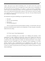
invested in its planning. Table 2.5. gives a sample description of the activities as a communication tool
in planning the project.
Activity Description
Project:
Project name
Page 1 of 1
Activity:
5.5.20.5 Evaluate Written Proposals
Description: Evaluate written proposals received from vendors in response to the RFP.
Inputs:
Requirements definition (5.5.5)
Effort:
Request for proposal (5.5.15)
Written proposals from vendors
Review vendor proposals
Reject proposals that do not meet mandatory requirements
Weight proposals for degree of compliance to optional requirements
Resources:
Outputs:
Prepare recommendations for short list
Project manager (20%)
Hardware analyst (80%)
Evaluation results consisting of:
Short list of qualified vendors or
Rejection of all proposals
Letters to vendors informing them of evaluation results
Table 2.5: Sample Activity Description
2.10. Planning phase
At the planning stage, you can deal with far more than the mere project at hand. You can also
shape the overall pattern of your team's working using the division and type of activities you assign.
The team must be involved in the planning of projects, especially in the lower levels of the
work breakdown structure. Not only will they provide information and ideas, but also they will feel
School of Electrical Engineering – University of Belgrade
PROJECT MANAGEMENT IN ENGINEERING
TYPICAL PHASES OF THE PROJECT IN POWER ELECTRONICS
35
ownership in the final plan. This does not mean that your projects should be planned by committee rather that you, as manager, plan the project based upon all the available experience and creative ideas.
As an initial approach, you could attempt the first level(s) of the work breakdown structure to help you
communicate the project to the team and then ask for comments. Then, using these, the final levels
could be refined by the people to whom the tasks will be allocated. However, since the specification is
so vital, all the team should vet the penultimate draft.
With planning, projects can run on time and interact effectively with both customers and
suppliers. Everyone involved understands what is wanted and emerging problems are seen (and dealt
with) long before they cause damage. If one wants project to run this way - then one’s must invest time
in planning.
2.11. Testing and Quality
No plan is complete without explicit provision for testing and quality. A wise manager will
know that this should be part of each individual phase of the project. This means that no activity is
completed until it has passed the (objectively) defined criteria which establishes its quality, and these
are best defined (objectively) at the beginning as part of the planning.
When devising the schedule therefore you must include allocated time for this part of each
activity. Thus your question is not only: "how long will it take", but also: "how long will the testing
take". By asking both questions together you raise the issue of "how do we know we have done it right"
at the very beginning and so the testing is more likely to be done in parallel with the implementation.
Another reason for stating the testing criteria at the beginning is that you can avoid futile quests
for perfection. If you have motivated your team well, they will each take pride in their work and want
to do the best job possible. The same is also true when choosing the tools or building-blocks of your
project. While it might be nice to have use of the most modern versions, or to develop an exact match
to your needs; often there is an old/existing version which will serve almost as well (sufficient for the
purpose), and the difference is not worth the time you would need to invest in obtaining or developing
the new one. A related idea is that you should discourage too much effort on aspects of the project
which are idiosyncratic to that one job. In the specification phase, you might try to eliminate these
through negotiation with the customer; in the implementation phase you might leave these parts until
last. The reason for this advice is that a general piece of work can be tailored to many specific
School of Electrical Engineering – University of Belgrade
PROJECT MANAGEMENT IN ENGINEERING
TYPICAL PHASES OF THE PROJECT IN POWER ELECTRONICS
36
instances; thus, if the work is in a general form, you will be able to rapidly re-use it for other projects.
On the other hand, if you produce something which is cut to fit exactly one specific case, you
may have to repeat the work entirely even though the next project is fairly similar. At the planning
phase, a manager should bare in mind the future and the long-term development of the team as well as
the requirements of the current project.
2.12. “Fighting” for time
As a project manager regulating the pressure and working load which is imposed upon team;
he/she must protect them from the unreasonable demands of the rest of the Institution working in. Once
have arrived at what manager considers being a realistic schedule, fighting for it. He/she never let the
outside world deflect from what he/she knows to be practical. If they impose a deadline which is
impossible, one will need to give some room for compromise, however, since a flat NO will be seen as
obstructive. Since one wants to help the Institution, one should look for alternative positions, offer a
prototype service or product at an earlier date. This might, in some cases, be sufficient for the customer
to start the next stage of his/her own project on the understanding that your project would be completed
at a later date and the final version would then replace the prototype.
In power electronics projects the complexity of the product, or the total number of units, might
be reduced. This might, in some cases, be sufficient for the customer's immediate needs. Future
enhancements or more units would then be the subject of a subsequent negotiation which, you feel,
would be likely to succeed since you will have already demonstrate your ability to deliver on time. You
can show on an alternative schedule that the project could be delivered by the deadline if certain
(specified) resources are given to you or if other projects are rescheduled. Thus, you provide a clear
picture of the situation and a possible solution; it is up to your manager then how he/she proceeds.
2.13. Planning for error
Recognizing that errors will occur is the reason for implementing a monitoring strategy on the
project. Thus when the inevitable does happen, one can react and adapt the plan to compensate.
However, being carefully in considering errors in advance can make changes to the original plan to
enhance its tolerance. Quite simply, planning should include time where one stand back from the
School of Electrical Engineering – University of Belgrade
PROJECT MANAGEMENT IN ENGINEERING
TYPICAL PHASES OF THE PROJECT IN POWER ELECTRONICS
37
design and ask: "what can go wrong?"; indeed, this is an excellent way of asking team for their
analysis of the plan.
In power electronics projects, if properly structured, mistakes can be avoided if there is reserved
plan (plan B). Very often each design have several alternatives, and if something goes wrong with the
first component it is always easy to switch on another one.
2.14. Closing out and deploying a Power Electronics projects
One of the characteristics that distinguish a project from other forms of business activity is that
a project ends. Once its purpose has been satisfied, it is closed and becomes part of organizational
history. Unfortunately, too many projects seem to drag on forever, coming to a grudging conclusion
more by attrition than by design.
At the end of any project, time allocation should be done, in order to review the lessons and
information on both the work itself and the management of that work: an open meeting, with open
discussion, with the whole team and all customers and suppliers. If one thinks that this might be
thought a waste of time by own manager, it is need to think of the effect it will have on future
communications with customers and suppliers. With all these considerations in merely the "planning"
stage of a project, it is perhaps surprising that projects get done at all. In fact projects do get done, but
seldom in the predicted manner and often as much by brute force as by careful planning. The point,
however, is that this method is non-optimal. Customers feel let down by late delivery, staff are
demotivated by constant pressure for impossible goals, corners get cut which harm your reputation, and
each project has to overcome the same problems as the last.
Just as there are proper ways to define, plan, and execute projects, so there is a right way to end
them. Closing a project involves three major steps: gaining client concurrence that the project is over,
capturing lessons learned during the project, and completing administrative closeout.
Power electronics projects are finished when the prototype is finished, together with technical
documentation, final report, but practical manual as well. The conference papers are a second effect on
power electronics projects, so each project brings several innovations that can be presented through
conferences, but later upgraded in other new projects.
School of Electrical Engineering – University of Belgrade
PROJECT MANAGEMENT IN ENGINEERING
TYPICAL PHASES OF THE PROJECT IN POWER ELECTRONICS
38
3. The role of Project Managers and Team Leaders in a project
Richard Pascale:
Managers do things right,
While leaders do the right thing
Leadership is just one of the many assets a successful manager must possess. Care must be
taken in distinguishing between the two concepts. The main aim of a manager is to maximize the
output of the organization through administrative implementation. To achieve this, managers must
undertake the following functions: organization, planning, staffing, directing, controlling…
Leadership is just one important component of the directing function. A manager cannot just be
a leader, he also needs formal authority to be effective. "For any quality initiative to take hold, senior
management must be involved and act as a role model. This involvement cannot be delegated." [1]
Managers think incrementally, while leaders think radically.
This means that managers do things by the book and follow company policy, while leaders
follow their own intuition, which may in turn be of more benefit to the company. A leader is more
emotional than a manager. "Men are governed by their emotions rather than their intelligence." [3]
This quotation illustrates why teams choose to follow leaders. "Leaders stand out by being different.
They question assumption and are suspicious of tradition. They seek out the truth and make decisions
based on fact, not prejudice. They have a preference for innovation." [4]
In some circumstances, leadership is not required. For example, self motivated groups may not
require a single leader and may find leaders dominating. The fact that a leader is not always required
proves that leadership is just an asset and is not essential. Each of the projects needs both, managers
and leaders. Project managers can be found in all industries. Their numbers have grown rapidly as
industry and commerce has realized that much of what it does is project work. And as project-based
organizations have started to emerge, project management is becoming established as both a
professional career path.
School of Electrical Engineering – University of Belgrade
PROJECT MANAGEMENT IN ENGINEERING
TYPICAL PHASES OF THE PROJECT IN POWER ELECTRONICS
39
3.1. Power Electronics Engineer as a Manager
Before starting any activity it is necessary to stop and think about it: what is the objective, how
can it be achieved, what are the alternatives, who need to be involved, what will it cost, is it worth
doing? When you have a plan it is necessary to stop and think about how to ensure that your plan is
working. You must find ways of monitoring your progress, even if it is just setting deadlines for
intermediate stages, or counting customer replies, whatever: choose something which displays progress
and establish a procedure to ensure that happens. But before you start, set a date on which it is
necessary to stop and rethink your plan in the light of the evidence gathered from the monitoring.
Whenever you have something to do consider not only the task but first the method. Thus if
there is a meeting to decide the cover for the new product you should initially ignore anything to do
with marketing slogans and decide:
1) how should the meeting be held,
2) who can usefully contribute,
3) how will ideas be best generated,
4) what criteria are involved in the decision,
5) is there a better way of achieving the same end.
Many of these decisions do not have a single "right" answer, the point is that they need to have
"an" answer so that the task is accomplished efficiently. Once the questions are posed, you can be
creative. The manger of a small team has three major roles to play: to be a planner, provider and a
protector.
3.1.1. Manager as a Planner
A Manager has to take a long-term view; indeed, the higher you rise, the further you will have
to look. While a team member will be working towards known and established goals, the manager must
look further ahead so that these goals are selected wisely. By thinking about the eventual consequences
of different plans, the manager selects the optimal plan for the team and implements it. By taking
account of the needs not only of the next project but the project after that, the manager ensures that
work is not repeated nor problems tackled too late, and that the necessary resources are allocated and
arranged.
In electrical engineering it is important always to think of entire project, and to try to locate the
current activity in a long term plan. For example, a testing phase is at the beginning of every big
activity, so estimating the length of testing is necessary to take into account all the time, and if
someone is not doing it well, there is a time to replace the member of the testing team.
School of Electrical Engineering – University of Belgrade
PROJECT MANAGEMENT IN ENGINEERING
TYPICAL PHASES OF THE PROJECT IN POWER ELECTRONICS
40
3.1.2. Manager as a Provider
The Manager has access to information and materials which the team needs. Often he/she has
the authority or influence to acquire things which no one else in the team could. This role for the
manager is important simply because no one else can do the job; there is some authority which the
manager holds uniquely within the team, and the manager must exercise this to help the team to work.
Not only authority, but experience is quite important in engineering projects, so the directions
set-up by manager is usually the right one. Manager is one that gives the support in additional
literature, specialized papers or software that will help other members on the project to respond to the
project requirements.
3.1.3. Manager as a Protector
The team needs security from the vagaries of less enlightened managers. In any company, there
are short-term excitements which can deflect the work-force from the important issues. The manager
should be there to guard against these and to protect the team. If a new project emerges which is to be
given to your team, you are responsible for costing it (especially in terms of time) so that your team is
not given an impossible deadline. If someone in your team brings forward a good plan, you must
ensure that it receives a fair hearing and that your team knows and understands the outcome. If
someone is in your team has a problem at work, you have to deal with it.
3.2. Manager’s role in the Power Electronics project
When you are struggling with a deadline or dealing with delicate decisions, the last thing you
want to deal with is "people". When the work is really on and the struggle is undecided, you want your
team to act co-operatively, quickly, rationally, you do not want a worker who avoids work, you do not
want your key engineer being tired all day. But this is what happens, and as a manager it is necessary to
deal with it. Few "people problems" can be solved quickly, some are totally beyond your control and
can only be contained; but you do have influence over many factors which affect your people and so it
is your responsibility to ensure that your influence is a positive one.
You can only underestimate the impact which you personally have upon the habits and
effectiveness of your group. As the leader of a team, you have the authority to sanction, encourage or
restrict most aspects of their working day, and this places you in a position of power - and
responsibility.
School of Electrical Engineering – University of Belgrade
PROJECT MANAGEMENT IN ENGINEERING
TYPICAL PHASES OF THE PROJECT IN POWER ELECTRONICS
41
3.2.1. Motivation
When thinking about motivation it is important to take the long-term view. What is needed is a
sustainable approach to maintain enthusiasm and commitment from your team. This is not easy; but it
is essential to effectiveness. What can influence is the local environment and particularly the way in
which you interact with your team. The positive motivators are: achievement, recognition, the work
itself, responsibility, and advancement. These are what your team needs; loads-o-money is nice but not
nearly as good as being valued and trusted.
As the manager, you set the targets - and in selecting these targets, you have a dramatic effect
upon your team's sense of achievement. If you make them too hard, the team will feel failure; if too
easy, the team feels little. Ideally, you should provide a series of targets which are easily recognized as
stages towards the ultimate completion of the task. Thus progress is punctuated and celebrated with
small but marked achievements. If you stretch your staff, they know you know they can meet that
challenge.
Recognition is about feeling appreciated. It is knowing that what you do is seen and noted, and
preferably by the whole team as well as by you, the manager. In opposite terms, if people do something
well and then feel it is ignored - they will not bother to do it so well next time (because "no one cares").
The feedback you give your team about their work is fundamental to their motivation. They
should know what they do well (be positive), what needs improving (be constructive) and what is
expected of them in the future (something to aim at). And while this is common sense, ask yourself
how many on your team know these things, right now? Perhaps more importantly, for which of your
team could you write these down now (try it)?
Your staff need to know where they stand, and how they are performing against your
(reasonable) expectations. You can achieve this through a structured review system, but such systems
often become banal formalities with little or no communication. The best time to give feedback is when
the event occurs. Since it can impact greatly, the feedback should be honest, simple, and always
constructive. If in doubt, follow the simple formula of:
1. highlight something good
2. point out what needs improving
3. suggest how to improve
School of Electrical Engineering – University of Belgrade
PROJECT MANAGEMENT IN ENGINEERING
TYPICAL PHASES OF THE PROJECT IN POWER ELECTRONICS
42
You must always look for something positive to say, if only to offer some recognition of the
effort which has been put into the work. When talking about improvements, be specific: this is what is
wrong, this is what I want/need, this is how you should work towards it. Never say anything as
unhelpful or uninformative as "do better" or "shape up" - if you cannot be specific and say how, then
keep quiet. While your team will soon realize that this IS a formula, they will still enjoy the benefits of
the information (and training). You must not stint in praising good work. If you do not acknowledge it,
it may not be repeated simply because no one knew you approved.
The work itself should be interesting and challenging. Interesting because this makes staff
actually engage their attention; challenging because this maintains the interest and provides a sense of
personal achievement when the job is done. But few managers have only interesting, challenging work
to distribute: there is always the boring and mundane to be done. You must actually consider how
interesting are the tasks you assign and how to deal with the boring ones.
3.2.2. Defining Problems
We are going to look at a simple system for addressing people-problems. It is a step-by-step
procedure which avoids complex psychological models (which few managers can/should handle) and
which focuses upon tangible (and so controllable) quantities. In any group of people there are bound to
be problems - as a manager, you have to solve or at least contain them. You ignore them at your peril.
Before proceeding, it is worth checking that the problem is real - some "problems" are more
appearance than substance, some are not worth you time and effort. So, stage 1 is to monitor the
identified problem to check that it is real and to seek simple explanations.
Stage 2 is often missed. This sort of interview can be quite difficult because you run the danger
of making personal criticism. Now you may feel that problem-maker deserves criticism, but does it
actually help? Your objective is to get problem-maker to work well, not to indulge in personal tyranny.
If you make it personal, problem-maker will be defensive. He/she will either deny the problem, blame
someone else, blame the weather, tell you that he/she knows best or some combination of the above. If,
on the other hand, you present the situation in terms of the specific events, you can focus upon
problem-maker 's own view of the problem (why is this happening?) and his/her own solution (what
can problem-maker do about it - can you help?).
Stage 2 will sometimes be sufficient. If problem-maker had not realised there was a problem,
he/she might act quickly to solve it. If he/she had thought his/her behaviour would pass unnoticed,
he/she now knows differently. By giving the responsibility for solving his own problem, you can
School of Electrical Engineering – University of Belgrade
PROJECT MANAGEMENT IN ENGINEERING
TYPICAL PHASES OF THE PROJECT IN POWER ELECTRONICS
43
actually motivate him/her beyond the specific problem: he/she may suggest on improved reporting
system, or a short training course to deal with a technical short-coming. Finally, the demonstration
alone that you are interested in problem-maker 's work may be enough to make him/her improve.
Never assume that you know better, always ask first - then if no solution is forthcoming, proceed to ...
Stage 3 is the analysis stage and is based upon a simple model of behaviour: every action is
preceded by a trigger, and is followed by a consequence or payoff. Sometimes, good behaviour is
blocked by negative payoffs.
Once you have analysed the problem, stage 4 is to find a solution. With most people-problems
at work, you will find that the "bad" behaviour is reinforced by a payoff which that person finds
attractive. There are two solutions: 1) modify the payoff either by blocking it, or by adding another
consequence which is negative, or 2) create a positive payoff for the alternative, desired "good"
behaviour. In the long term, the latter is preferable since it is better for motivation to offer
encouragement rather than reprimand; optimally you should implement both.
This is where manager need to be creative, providing the solution. It is best to work on one
problem at a time because this simplifies the analysis. Further, by addressing one, other related
problems are often affected also.
Stage 5 is necessary because such plans do not always work. You must continue to monitor the
problem and after a trial period, review your progress. If the plan is working, continue; if the plan has
failed, devise a new one; if the plan has worked, look for a new problem to solve.
3.2.3. Seeking the Solutions
The range of problems is so large, that it is impossible to offer more than generalities as advise.
Each person is different, each situation is different, so each solution must be carefully crafted. This
being said, here are a few ideas. Look for aspects of motivation - any problem which stems from lack
of commitment or interest can only successfully be addressed by providing motivation, and any of the
motivators described earlier can be applied.
Be flexible with regards to personal problems. When circumstances and the human factor
impinge upon your ordered plans, adapt; since you cannot change it, work with it. Focus upon the
problem (say, schedule slippage) and deal with that in the existing situation. On a larger scale, look
carefully at the "systems" which exist in your team, at those work practices which you and they follow
through habit. Some of these can work against you, and the team. For instance, the way you hold team
School of Electrical Engineering – University of Belgrade
PROJECT MANAGEMENT IN ENGINEERING
TYPICAL PHASES OF THE PROJECT IN POWER ELECTRONICS
44
meetings may suppress contributions (at 4 o'clock on a Friday, say); the way you reward the
exceptional may demotivate those responsible for the mundane.
Take a long term view. Constant pressure will eventually destroy your team members. If you
acknowledge that a relaxed yet engaged workforce is (say) 10% more efficient than one which is overstressed and fretful, then you should realize that this amounts to half-a-day per week. So why not
devote half-a-day to: peer-group teaching, brainstorming on enhanced efficiency, visits to customers
(internal and external), guest lectures on work tools, or all four on a four-weekly cycle. You lose
nothing if you gain a skilled, committed, enthusiastic team.
Finally, look carefully at how you behave and whether the current situation is due to your previous
inattention to the human factor: you might be the problem, and the solution.
3.3. Manager’s problem of delegation
Delegation is a skill of which all of us heard - but which few understand. It can be used either as
an excuse for dumping failure onto the shoulders of subordinates, or as a dynamic tool for motivating
and training your team to realize their full potential. Delegation underpins a style of management
which allows your staff to use and develop their skills and knowledge to the full potential. Without
delegation, you lose their full value.
Delegation is primarily about entrusting your authority to others. This means that they can act
and initiate independently; and that they assume responsibility with you for certain tasks. If something
goes wrong, you remain responsible since you are the manager; the trick is to delegate in such a way
that things get done but do not go (badly) wrong.
3.3.1. The objective of delegation
The objective of delegation is to get the job done by someone else. Not just the simple tasks of
reading instructions and turning a lever, but also the decision making and changes which depend upon
new information. With delegation, your staff have the authority to react to situations without referring
back to you. To enable someone else to do the job for you, you must ensure that:
•
they know what you want
School of Electrical Engineering – University of Belgrade
PROJECT MANAGEMENT IN ENGINEERING
•
•
TYPICAL PHASES OF THE PROJECT IN POWER ELECTRONICS
45
they have the authority to achieve it
they know how to do it.
These all depend upon communicating clearly the nature of the task, the extent of their discretion, and
the sources of relevant information and knowledge.
3.3.2. Delegation - Information
Such a system can only operate successfully if the decision-makers (your staff) have full and
rapid access to the relevant information. This means that you must establish a system to enable the flow
of information. This must at least include regular exchanges between your staff so that each is aware of
what the others are doing. It should also include briefings by you on the information which you have
received in your role as manager; since if you need to know this information to do your job, your staff
will need to know also if they are to do your (delegated) job for you.
One of the main claims being made for computerized information distribution is that it
facilitates the rapid dissemination of information. You may not believe this vision, but you should
understand the premise. If a manager restricts access to information, then only he/she is able to make
decisions which rely upon that information; once that access is opened to many others, they can make
decisions too - and challenge those of the manager according to additional criteria.
3.3.3. Effective control of delegation
One of the main phobias about delegation is that by giving others authority, a manager loses
control. This need not be the case. If you train your staff to apply the same criteria as you would
yourself (by example and full explanations) then they will be exercising your control on your behalf.
And since they will witness many more situations over which control may be exercised (you can't be in
several places at once) then that control is exercised more diversely and more rapidly than you could
exercise it by yourself. In engineering terms: if maintaining control is truly your concern, then you
should distribute the control mechanisms to enable parallel and autonomous processing.
3.3.4. Staggered Development in delegation
To understand delegation, you really have to think about people. Delegation cannot be viewed
as an abstract technique, it depends upon individuals and individual needs. Let us take a lowly member
of staff who has little or no knowledge about the job which needs to be done.
School of Electrical Engineering – University of Belgrade
PROJECT MANAGEMENT IN ENGINEERING
TYPICAL PHASES OF THE PROJECT IN POWER ELECTRONICS
46
The key is to delegate gradually. If you present someone with a task which is daunting, one
with which he/she does not feel able to cope, then the task will not be done and your staff will be
severely demotivated. Instead you should build-up gradually; first a small task leading to a little
development, then another small task which builds upon the first; when that is achieved, add another
stage; and so on. This is the difference between asking people to scale a sheer wall, and providing them
with a staircase. Each task delegated should have enough complexity to stretch that member of staff but only a little.
3.3.5. Outcomes and Failures in Delegating
Let consider undoubtedly high standards. When delegate a job, it does not have to be done as
well as you could do it (given time), but only as well as necessary: never judge the outcome by what
you expect you would do (it is difficult to be objective about that), but rather by fitness for purpose.
When you delegate a task, agree then upon the criteria and standards by which the outcome will be
judged. You must enable failure. With appropriate monitoring, you should be able to catch mistakes
before they are catastrophic; if not, then the failure is yours.
3.3.6. What to delegate
There is always the question of what to delegate and what to do yourself, and you must take a
long term view on this: you want to delegate as much as possible to develop you staff to be as good as
you are now. The starting point is to consider the activities you used to do before you were promoted.
You used to do them when you were more junior, so someone junior can do them now. Tasks in which
you have experience are the easiest for you to explain to others and so to train them to take over. You
thus use your experience to ensure that the task is done well, rather than to actually perform the task
yourself. In this way you gain time for your other duties and someone else becomes as good as your
once were (increasing the strength of the group).
Tasks in which your staff have more experience must be delegated to them. This does not mean
that you relinquish responsibility because they are expert, but it does mean that the default decision
should be theirs. To be a good manager though, you should ensure that they spend some time in
explaining these decisions to you so that you learn their criteria. Decisions are a normal managerial
function: these too should be delegated - especially if they are important to the staff. In practice, you
will need to establish the boundaries of these decisions so that you can live with the outcome, but this
will only take you a little time while the delegation of the remainder of the task will save you much
more.
School of Electrical Engineering – University of Belgrade
PROJECT MANAGEMENT IN ENGINEERING
TYPICAL PHASES OF THE PROJECT IN POWER ELECTRONICS
47
In terms of motivation for your staff, you should distribute the more mundane tasks as evenly as
possible; and sprinkle the more exciting onces as widely. In general, but especially with the boring
tasks, you should be careful to delegate not only the performance of the task but also its ownership.
Task delegation, rather than task assignment, enables innovation. The point you need to get across is
that the task may be changed, developed, upgraded, if necessary or desirable. So someone who collates
the monthly figures should not feel obliged to blindly type them in every first-Monday; but should feel
empowered to introduce a more effective reporting format, to use Computer Software to enhance the
data processing, to suggest and implement changes to the task itself.
3.3.7. Delegation - When all is done for the Manager
Once the Manager has delegated everything, what does he do then? He/she still need to monitor
the tasks he/she has delegated and to continue the development of staff to help them exercise their
authority well. There are managerial functions which you should never delegate - these are the
personal/personnel ones which are often the most obvious additions to your responsibilities as you
assume a managerial role. Specifically, they include: motivation, training, team-building, organization,
praising, reprimanding, performance reviews, promotion.
As a manager, you have a responsibility to represent and to develop the effectiveness of your
group within the company; these are tasks you can expand to fill your available time - delegation is a
mechanism for creating that opportunity.
School of Electrical Engineering – University of Belgrade
PROJECT MANAGEMENT IN ENGINEERING
TYPICAL PHASES OF THE PROJECT IN POWER ELECTRONICS
48
3.4. Power Electronics Engineer as a Leader
Leadership is a way of focusing and motivating a group to enable them to achieve their aims. It
also involves being accountable and responsible for the group as a whole. A leader should: provide
continuity and momentum and to be flexible in allowing changes of direction. Ideally, a leader should
be a few steps ahead of their team, but not too far for the team to be able to understand and follow
them. Leaders must have a wide range of skills, techniques and strategies. These include:
•
•
•
•
Planning
Communication skills
Organization
Awareness of the wider environment in which the team operates.
There is a debate about whether leadership should be concentrated in one person or distributed
among members of the team. Traditionally, a permanent team leader would be appointed by more
senior levels of management or elected by the group. This technique relies on the assumption that one
single person has all the strengths required. However, it has been argued that "on the best teams,
different individuals provide occasional leadership, taking charge in areas where they have particular
strengths, so no one is the permanent leader, because that person would then cease to be a peer and
the team interaction would begin to break down" [1].
If speaking about engineer as a leader, it is a person that clearly understands the final prototype,
knows most of the steps, even several steps further more. A leader - an obsessed engineer will be the
one who brings ideas and solving potential problems on the project, but spending not as much time as
managers do with a team.
This approach would eliminate the problem of a leader being isolated from group. It must be
emphasized, however, that continuity and focus of the group must not be lost. Thus, in our opinion, the
best compromise may be to have a permanent leader who is flexible enough not only to delegate
responsibility for individual tasks, but also to let others take leadership of the team as required. A
leader is someone who people naturally follow through their own choice, whereas a manager must be
obeyed. A manager may only have obtained his position of authority through time and loyalty given to
the company, not as a result of his leadership qualities. A leader may have no organizational skills, but
his vision unites people behind him.
School of Electrical Engineering – University of Belgrade
PROJECT MANAGEMENT IN ENGINEERING
TYPICAL PHASES OF THE PROJECT IN POWER ELECTRONICS
49
3.4.1. Leadership Attitudes
One way of looking at different leadership styles is in terms of task orientation versus
employee orientation.
•
•
Task Orientation or Directive Behaviour. This reflects how much a leader is concerned with the
actual task at hand and ensuring that those following him complete it.
Employee Orientation or Supportive Behaviour. This reflects how much a leader is concerned
for the people around him, providing support and encouragement for them.
The combination of these two effects lead to the following diagram:
1. Country Club Management
2. SUPPORTING
1. Team Management
2. COACHING
1. Impoverished Management 1. Authority/Obedience Management
2. DELEGATING
2. DIRECTING
This diagram can be used in two ways:
•
•
As a guide to how effective your leadership style is. Your general attitude to the leadership of
the group will fall into one of these categories.
As a guide to how best to lead different individuals using different styles to make the most
efficient use of both their, and your, time and talents.
If you have a group of widely differing levels of ability, confidence and commitment, you may
want to lead them each with a different style.
Directing. A team member who has a lot of enthusiasm for the job but not much actual ability,
for example a new start, will need to be directed. You will not need to spend much time giving
encouragement or coaxing them along. You will however have to tell them what to do next after they
complete every task, and how to do the tasks set.
Coaching. After being in the group for a while, somebody might begin to lose confidence and
therefore motivation, as they still can't seem to do the work they want to do. At this stage you will need
to coach them along. You will still need to tell them what to do at virtually every point along the way,
while taking care to encourage them and praise them at every turn.
School of Electrical Engineering – University of Belgrade
PROJECT MANAGEMENT IN ENGINEERING
TYPICAL PHASES OF THE PROJECT IN POWER ELECTRONICS
50
Supporting. Gradually the team member's technical ability will increase until they are at a
stage where they can actually do everything required of them, however they may still lack the
confidence to actually do it off their own backs. You should no longer have to tell them what to do,
although they may think otherwise. You should seek their opinions on the next stage, and be seen to
take notice of their ideas.
Delegating. A technically competent person's confidence will gradually grow until they feel
able to work completely on their own. You should now be able to delegate specific areas of work to
them and feel little need to tell them either what to do or to praise them as frequently for doing it. The
time that you don't have to spend "leading" these members of the group can be spent with the less
experienced group members, or on the work that you need to do.
3.4.2. Leadership Styles
The role of leadership in management is largely determined by the organisational culture of the
one team. It has been argued that managers' beliefs, values and assumptions are of critical importance
to the overall style of leadership that they adopt.There are several different leadership styles that can be
identified within each of the following Management techniques. Each technique has its own set of good
and not-so-good characteristics, and each uses leadership in a different way.
The autocratic leader dominates team-members, using unilateralism to achieve a singular
objective. This approach to leadership generally results in passive resistance from team-members and
requires continual pressure and direction from the leader in order to get things done. Generally, an
authoritarian approach is not a good way to get the best performance from a team.There are, however,
some instances where an autocratic style of leadership may not be inappropriate. Some situations may
call for urgent action, and in these cases an autocratic style of leadership may be best. In addition, most
people are familiar with autocratic leadership and therefore have less trouble adopting that style.
Furthermore, in some situations, sub-ordinates may actually prefer an autocratic style.
The democratic leader makes decisions by consulting his team, whilst still maintaining control
of the group. The democratic leader allows his team to decide how the task will be tackled and who
will perform which task. A good democratic leader encourages participation and delegates wisely, but
never loses sight of the fact that he bears the crucial responsibility of leadership. He values group
discussion and input from his team and can be seen as drawing from a pool of his team members'
strong points in order to obtain the best performance from his team. He motivates his team by
empowering them to direct themselves, and guides them with a loose reign.However, the democrat can
School of Electrical Engineering – University of Belgrade
PROJECT MANAGEMENT IN ENGINEERING
TYPICAL PHASES OF THE PROJECT IN POWER ELECTRONICS
51
also be seen as being so unsure of himself and his relationship with his sub-ordinates that everything is
a matter for group discussion and decision. Clearly, this type of "leader" is not really leading at all.
3.4.3. Becoming a Leader
A leader may not always be a manager, and one day you may see an opportunity to lead a
project or team within your group, but when do decide the time is right and how do you go about
becoming the leader? Here are the steps to become an effective leader:
1. Identify team members and resources willing to support your leadership. Clearly, change may
be resisted by some people or organisations, but if you can find enough support this resistance
can be overcome. Note that the support of your team may not be enough if you do not have the
support of authority (the boss for example) or the physical/financial resources to accomplish
your goals.
2. A crucial step is to empathise with others and assess their understanding of the situation. This
will help you understand how to influence these people. Many ways of doing this are available:
memos, phone calls and informal chats are a few examples.
3. Now you should open a discussion which the members. Clearly, without open discussion some
people may feel neglected or excluded. By getting everyone's views it is more likely that you
will be able to alter them and get what you want. Now you must convince the others that your
view is the one most likely to achieve a favourable outcome for everyone. This may be easy if
everyone shares the same goals, or it may be difficult. In the end some form of 'payment' may
be required, such as a promise of a favour, to convince certain members. This is easy if you are
in a position of power, if not, make sure the cost to yourself is not too high.
4. Having convinced the team of your leadership, encourage team communication to build a team
identity. You should also try to motivate the team appropriately.
5. Plan and organise the team by setting realistic goals. However do not give too much or too little
guidance, experienced workers may resent you treating them like new-recruits, and this can
undermine your leadership.
6. When goals are achieved recognise and reward the team. Do not expect the team to exceed
them - this will undermine your leadership and the team will lose trust in you. Of course you
may decide that the goals are unachievable or insufficient, but any re-definition of these goals
should be done carefully and with team co-operation.
School of Electrical Engineering – University of Belgrade
PROJECT MANAGEMENT IN ENGINEERING
TYPICAL PHASES OF THE PROJECT IN POWER ELECTRONICS
52
3.5. The image of the Leader in Engineering
The leader is a multicultural person, that develops own cultural sensitivity by observing and
understanding cultural differences. But also appreciates the wide variety of people who fit under the
diversity umbrella, such as recognizing that workers differ from one another. The leader recognizes
differences in cultural attitudes and values in such dimensions as formality versus informality and
attitude toward time, and also establishes a good strategy for motivating people from different cultures
including identifying their motivation.
Engineer can be a leader if can understand the need of variety of engineers on the same project
working with the same value of motivation gaining the same objective. One of the most important
characteristic is an experience, which will help an engineer-leader to estimate number of engineers,
time, finance and make a functional communication among team members.
Here are presented some main characteristics of an effective leader:
Guiding vision. Effective leaders know what they want to do, and have the strength of character to
pursue their objectives in the face of opposition and in spite of failures.
Goals. The effective leader establishes achievable goals.
Integrity. Because they know who they are, effective leaders are also aware of their weaknesses. They
only make promises they can follow through on.
Honesty. Leaders convey an aura of honesty in both their professional and their personal lives.
Effective leaders earn the trust of their followers and act on behalf of their followers.
Self-Confidence. How can you build up your self-confidence? Thinking positive thoughts about
yourself or writing down your good points to boost your self-confidence, maybe visualizing a more
powerful you, or maybe following a few easy victories with bigger challenges, sometimes is good to
try with dealling creatively with the emotional turmoil associated with adversity
Communication. Leaders use heavy-impact, embellishing language full of metaphors, analogies, and
anecdotes for inspiring group members. They rather use skillfully body language or power-oriented
School of Electrical Engineering – University of Belgrade
PROJECT MANAGEMENT IN ENGINEERING
TYPICAL PHASES OF THE PROJECT IN POWER ELECTRONICS
53
language style for a comprehensive approach. Leaders often avoid detractors such as junk words,
vocalized pauses, insipid clichés threadbare anecdotes, and turning to many nouns into verbs.
Curiosity. Leaders are learners. They wonder about every aspect of their charge. They find out what
they need to know in order to pursue their goals.
Risk. Effective leaders take calculated risks when necessary to achieve their objectives. If a mistake is
made, the effective leader will learn from the mistake and use it as an opportunity to explore other
avenues.
Thinking. Leaders pay attention to their intuition in order to recognize the importance of being a big
thinker for effective leadership. They are not afraid to ask tough questions, and enhance their ability to
read people whenever possible.
Dedication. The effective leader is dedicated to his or her charge, and will work assiduously on behalf
of those following. The leader gives himself or herself entirely to the task when it is necessary.
Charisma. This may be the one attribute that is the most difficult to cultivate. It conveys maturity,
respect for your followers, compassion, a fine sense of humor, and a love of humanity. The result is
that leaders have the capability to motivate people to excel. Charisma is recognized as a major
leadership quality, because to lead others without charisma puts the leader at a disadvantage. Many of
the qualities associated with charisma can be developed and most effective method of developing or
enhancing charisma include learning to express the feelings more assertively and becoming more
enthusiastic, optimistic and energetic.
Listening. Leaders Listen! This is the most important attribute of all, listen to your followers.
Passion. Effective leaders believe passionately in their goals. They have a positive outlook on who
they are, and they love what they do. Their passion for life is a guiding star for others to follow,
because they radiate promise!
The image of the leader is present in any occation. The way leader stand or sit indicates
whether he/she is an open person, easily approachable, also says whether is friendly. Sometimes that
can tells others about ability to be a good team player or maybe suggests about being frank and honest,
also tells others what the person (the leader) really thinks of them shows whether he/she is part of the
team. Also The way leader dresses indicates whether person has conventional ideas or whether he/she
School of Electrical Engineering – University of Belgrade
PROJECT MANAGEMENT IN ENGINEERING
TYPICAL PHASES OF THE PROJECT IN POWER ELECTRONICS
54
is “a radical”, that can shows his/her neatness, or just suggests whether person (leader) will fit in with
the company's image. Sometimes dressing makes a statement about whether or not person cares enough
to find out about the company, its image and its objectives and shows indirectly whether person is
confident, whether or not believes in himself/herself. The way of writing conveys can indicate
whether person is warm and friendly or appear cool and reserved, whether is dynamic and energetic or
are lethargic and procrastinate. An image of someone as either intuitive in solving problems, or logical,
solving problems step by step, whether or not he/she wants to communicate with others, whether is
trying to avoid conflict or seek it, and at least whether is materialistic or idealistic.
3.6. Time management for Managers and Leaders
Time Management is about controlling the use of most valuable (and undervalued) resource.
The absence of Time Management is characterized by last minute rushes to meet dead-lines, meetings
which are either double booked or achieve nothing, days which seem somehow to slip unproductively
by, crises which loom unexpected from nowhere. This sort of environment leads to inordinate stress
and degradation of performance: it must be stopped.
Poor time management is often a symptom of over confidence: techniques which used to work
with small projects and workloads are simply reused with large ones. But inefficiencies which were
insignificant in the small role are ludicrous in the large. The demands, the problems and the payoffs for
increased efficiency are all larger as your responsibility grows; you must learn to apply proper
techniques or be bettered by those who do. Possibly, the reason Time Management is poorly practised
is that it so seldom forms a measured part of appraisal and performance review; what many fail to
foresee, however, is how intimately it is connected to aspects which do.
3.6.1. Personal time Management
Personal Time Management has many facets also. Most managers recognize a few, but few
recognize them all. There is the simple concept of keeping a well ordered diary and the related idea of
planned activity. But beyond these, it is a tool for the systematic ordering of your influence on events,
it underpins many other managerial skills such as Effective Delegation and Project Planning.
Personal Time Management is a set of tools which allow you to:
• eliminate wastage
School of Electrical Engineering – University of Belgrade
PROJECT MANAGEMENT IN ENGINEERING
TYPICAL PHASES OF THE PROJECT IN POWER ELECTRONICS
55
• be prepared for meetings
• refuse excessive workloads
• monitor project progress
• allocate resource (time) appropriate to a task's importance
• ensure that long term projects are not neglected
• plan each day efficiently
• plan each week effectively
and to do so simply with a little self-discipline.
Since Personal Time Management is a management process just like any other, it must be planned,
monitored and regularly reviewed. Before we start on the future, it is worth considering the present.
This involves the simplistic task of keeping a note of how manager or leader spend time for a suitably
long period of time (say a week).
3.6.2. Waste Disposal
There are various sources of waste. The most common are social: telephone calls, friends
dropping by, conversations around the coffee machine. It would be foolish to eliminate all non-work
related activity (we all need a break) but if it's a choice between chatting to Harry in the afternoon and
meeting the next pay-related deadline ... Your time log will show you if this is a problem and you
might like to do something about it before your boss does.
Time is often wasted in changing between activities. For this reason it is useful to group similar
tasks together thus avoiding the start-up delay of each. The time log will show you where these savings
can be made. You may want then to initiate a routine which deals with these on a fixed but regular
basis.
3.6.3. Deadlines
The most daunting external appointments are deadlines: often, the handover of deliverables.
The basic idea is that management of deadlines should be achieved with exactly techniques of any
project:
• check the specification - being sure that everything is agree on what is to be delivered
• break the task down into small sections so that can estimate the time needed for each, and monitor
progress
School of Electrical Engineering – University of Belgrade
PROJECT MANAGEMENT IN ENGINEERING
TYPICAL PHASES OF THE PROJECT IN POWER ELECTRONICS
56
• schedule reviews of progress (e.g. after each sub-task) so that can respond quickly to difficulties
Like most management ideas, this is common sense. Some people, however, refute it because in
practise they find that it merely shows the lack of time for a project which must be done anyway. This
is simply daft! If simple project planning and time management show that the task can not be done,
then it will not be done - but by knowing at the start, you have a chance to do something about it.
An impossible deadline affects not only your success but also that of others. Suppose a product
is scheduled for release too soon because you agree to deliver too early. By practising time
management, you will always have a clear understanding of how you spend your time and what time is
unallocated. If a new task is thrust upon you, you can estimate whether it is practical. The project
planning tells you how much time is needed and the time management tells you how much time is
available.
There are four ways to deal with impossible deadlines:
• Get the deadline extended
• Scream for more resources
• Get the Deliverable redefined to something practical
• State the position clearly so that leader have fair warning
If this simple approach seems unrealistic, consider the alternative. If you have an imposed, but
unobtainable, deadline and you accept it; then the outcome is your assured failure. One defence tactic is
to present your superior with a current list of your obligations indicating what impact the new task will
have on these current ones.
Finally, for each activity you should estimate how much time it is worth and allocate only that
amount. This critical appraisal may even suggest a different approach or method so that the time
matches the task's importance. Beware of perfection, it takes too long - allocate time for "fitness for
purpose", then stop.
3.6.4. Monitoring Staff
Time Management also effects other people, particularly subordinates. Planning projects means
not only allocating time but also the distribution of tasks; and this should be done in the same planned,
monitored and reviewed manner as your own scheduling. Any delegated task should be specified with
an (agreed) end date. As a Manager, you are responsible for ensuring that the tasks allocated to your
School of Electrical Engineering – University of Belgrade
PROJECT MANAGEMENT IN ENGINEERING
TYPICAL PHASES OF THE PROJECT IN POWER ELECTRONICS
57
subordinates are completed successfully. Thus you should ensure that each task is concluded with a
deliverable (for instance, a memo to confirm completion) - you make an entry in your diary to check
that this has arrived. Thus, if you agree the task for Tuesday, Wednesday should have an entry in your
diary to check the deliverable. This simple device allows you to monitor progress and to initiate action
as necessary.
3.6.5. Long term Objectives
There are many long term objectives which the good Manager must achieve, particularly with
regard to the development, support and motivation of his/her work-team. Long term objectives have the
problem of being important but not urgent; they do not have deadlines, they are distant and remote. For
this reason, it is all too easy to ignore them in favour of the urgent and immediate. Clearly a balance
must be struck.
The beauty of Time Management is that the balance can be decided objectively (without
influence from immediate deadlines) and self-imposed through the use of the diary. Simply, a manager
might decide that one hour a week should be devoted to personnel issues and would then allocate a
regular block of time to that activity. Time may be allocated to staff development and training. The
actual time spent in managing this sort of long term objective is small, but without that deliberate
planning it will not be achieved.
3.7. Forming the team
Teams are like relationships - you have to work at them. In the work place, they constitute an
important unit of activity but one whose support needs are only recently becoming understood. By
making the group itself responsible for its own support, the responsibility becomes an accelerator for
the group process. What is vital, is that these needs are recognized and explicitly dealt with by the
team. Time and resources must be allocated to this by the group and by Management, and the group
process must be planned, monitored and reviewed just like any other managed process.
Groups form a basic unit of work activity throughout engineering and yet the underlying
process is poorly managed. In the beginning, When people work in groups, there are two quite separate
issues involved. The first is the task and the problems involved in getting the job done. Frequently this
is the only issue which the group considers. The second is the process of the group work itself: the
mechanisms by which the group acts as a unit and not as a loose rabble. However, without due
School of Electrical Engineering – University of Belgrade
PROJECT MANAGEMENT IN ENGINEERING
TYPICAL PHASES OF THE PROJECT IN POWER ELECTRONICS
58
attention to this process the value of the group can be diminished or even destroyed; yet with a little
explicit management of the process, it can enhance the worth of the group to be many times the sum of
the worth of its individuals. It is this synergy which makes group work attractive in corporate
organization despite the possible problems (and time spent) in group formation.
3.7.1. Definition of the team
Team presents a group of people working in the same room, or even on a common project, does
not necessarily invoke the group process. If the group is managed in a totally autocratic manner, there
may be little opportunity for interaction relating to the work; if there is fractioning within the group, the
process may never evolve. On the other hand, the group process may be utilized by normally distant
individuals working on different projects; for instance, at IEE colloquia.
In simple terms, the team process leads to a spirit of cooperation, coordination and commonly
understood procedures and mores. If this is present within a group of people, then their performance
will be enhanced by their mutual support (both practical and moral). If you think this is a nebulous
concept when applied to the world of industry, consider the opposite effect that a self-opinionated,
cantankerous loud-mouth would have on your performance and then contrast that to working with a
friendly, open, helpful associate. Teams are particularly good at combining talents and providing
innovative solutions to possible unfamiliar problems; in cases where there is no well established
approach/procedure, the wider skill and knowledge set of the group has a distinct advantage over that
of the individual.
In general, however, there is an overriding advantage in a team-based work force which makes
it attractive to Management: that it engenders a fuller utilization of the work force. A team can be seen
as a self managing unit. The range of skills provided by its members and the self monitoring which
each group performs makes it a reasonably safe recipient for delegated responsibility. Even if a
problem could be decided by a single person, there are two main benefits in involving the people who
will carry out the decision. Firstly, the motivational aspect of participating in the decision will clearly
enhance its implementation. Secondly, there may well be factors which the implementer understands
better than the single person who could supposedly have decided alone.
School of Electrical Engineering – University of Belgrade
PROJECT MANAGEMENT IN ENGINEERING
TYPICAL PHASES OF THE PROJECT IN POWER ELECTRONICS
59
3.7.2. Team Development
It is common to view the development of a team as having four stages:
Forming is the stage when the group first comes together. Everybody is very polite and very
dull. Conflict is seldom voiced directly, mainly personal and definitely destructive. Since the grouping
is new, the individuals will be guarded in their own opinions and generally reserved. This is
particularly so in terms of the more nervous and/or subordinate members who may never recover. The
group tends to defer to a large extent to those who emerge as leaders (poor fools!).
Storming is the next stage, when all Hell breaks loose and the leaders are lynched. Factions
form, personalities clash, no-one concedes a single point without first fighting tooth and nail. Most
importantly, very little communication occurs since no one is listening and some are still unwilling to
talk openly. True, this battle ground may seem a little extreme for the groups to which you belong - but
if you look beneath the veil of civility at the seething sarcasm, invective and innuendo, perhaps the
picture come more into focus.
Then comes the Norming. At this stage the sub-groups begin to recognize the merits of working
together and the in-fighting subsides. Since a new spirit of co-operation is evident, every member
begins to feel secure in expressing their own view points and these are discussed openly with the whole
group. The most significant improvement is that people start to listen to each other. Work methods
become established and recognized by the group as a whole.
And finally: Performing. This is the culmination, when the group has settled on a system which allows
free and frank exchange of views and a high degree of support by the group for each other and its own
decisions.
In terms of performance, the team starts at a level slightly below the sum of the individuals'
levels and then drops abruptly to its nadir until it climbs during Norming to a new level of Performing
which is (hopefully) well above the start. It is this elevated level of performance which is the main
justification for using the group process rather than a simple group of staff.
School of Electrical Engineering – University of Belgrade
PROJECT MANAGEMENT IN ENGINEERING
TYPICAL PHASES OF THE PROJECT IN POWER ELECTRONICS
60
3.8. Building Quality into the Team
In current management writings "Quality" has come to refer to a whole gambit of practices
which themselves have resulted in beneficial side-effects; a Team Leader will want to take advantage
of these benefits also. In simple terms, attaining Quality has something to do with satisfying the
expectations of the customer. Concern for the wishes and needs of customers becomes the focus for
every decision. Through careful education by competitors, the customer has begun to exercise spending
power in favour of quality goods and services; and while quality is not the sole criterion in selecting a
particular supplier, it has become an important differentiator. In the case where the product is a service,
Quality is equated with how well the job is done and especially with whether the customer is made to
feel good about the whole operation. In this respect Quality often does cost more, but the loss is
recouped in the price customers are prepared to pay.
The clearest manifestation of Quality is in a product's reliability: that the product simply works.
To prevent problems from arising after the product is shipped, the quality must be checked before-hand
- and the best time to check quality is throughout the whole design and manufacturing cycle. The old
method of quality control was to test the completed product and then to rework to remove the
problems. The new approach to quality simply asserts that if testing becomes an integral part of each
stage of production, the production time may increase but the rework time will disappear.
In seeking to improve the quality of the product, manufacturers have found that the people best
placed to make substantial contributions are the workforce: people are the most valuable resource. It is
this shift in perspective from the management to the workforce which is the most significant
consequence of the search for quality. From it has arisen a new managerial philosophy aimed at the
empowerment of the workforce, decision-making by the front line, active worker involvement in the
company's advancement; and from this new perspective, new organizational structures have evolved,
exemplified in "Quality Circles".
One outcome of the search for Quality in Japan is the system of Just-In-Time flow control. In
this system, goods arrive at each stage of the manufacturing process just before they are needed and are
not made until they are needed by the next stage. This reduces storage requirements and inventory costs
of surplus stock. Another outcome has been the increased flexibility of the production line. Time to
change from one product run to the next was identified as a major obstacle in providing the customer
with the desired range of products and quantities, and so the whole workforce became engaged in
changing existant practices and even in redesigning the machinery.
School of Electrical Engineering – University of Belgrade
PROJECT MANAGEMENT IN ENGINEERING
TYPICAL PHASES OF THE PROJECT IN POWER ELECTRONICS
61
3.8.1. Team Leader and Team Quality
While the salvation of an entire corporation may rest primarily with Senior Management, the
fate of a team rests with the Team Leader. The Team Leader has the authority, the power to define the
micro-culture of the work team. It is by the deliberate application of the principles of Quality that the
Team Leader can gain for the team the same benefits which Quality can provide for a corporation. The
best ideas for any particular team are likely to come from them - the aim of the Team Leader must be to
act as a catalyst through prompts and by example; the following are possible suggestions.
There will be no overnight success. To be lasting, Quality must become a habit and a habit is
accustomed practise. This takes time and training - although not necessarily formal training but
possibly the sort of reinforcement you might give to any aspect of good practise. To habituate staff to
Quality, leader must first make it an issue.
The initial phases are delicate. The team will be feeling greater responsibility without extra
confidence. Thus leader must concentrate on supporting their development. Essentially he/she will be
their trainer in management skills. Leader could get outside help with this but by undertaking the job
him/herself, he/she retain control: mould the team so that they will reflect his/her own approach and
use his/her own criteria. Later they will develop themselves, but even then they will understand
leader’s thinking and so leader ‘s decisions.
As with all team work, the main problem is clarity. Leader should provide the team with a
notice board and flip-charts specifically for Quality problems. These can then be left on display as a
permanent record of what was agreed. If one can, steer the group first to some problem which has a
simple solution and with obvious (measurable) benefits. A quick, sharp success will motivate.
3.8.2. Team Building
To succeed, a Quality push must engage the enthusiasm of the entire team; so Team Leader,
must create the right atmosphere for this to happen. Many aspects of team building can be addressed
while Quality remains the focus.
Leader must create the environment where each team member feels totally free to express an
idea or concern and this can only be done if there is no stigma attached to being incorrect. No idea is
wrong - merely non-optimal. In each suggestion there is at least a thread of gold and someone should
point it out and, if possible, build upon it. Any behaviour which seeks laughter at the expense of others
must be swiftly reprimanded.
School of Electrical Engineering – University of Belgrade
PROJECT MANAGEMENT IN ENGINEERING
TYPICAL PHASES OF THE PROJECT IN POWER ELECTRONICS
62
Most importantly, leader must enable failure. If the team is unable to try out ideas without
rebuke for errors, then the scope of their solutions will be severely limited. Instead, a failure should be
an opportunity to gain knowledge and to praise any safe-guards which were included in the plan.
One of the central tenets of Quality programmes is the idea of monitoring the problem being
addressed: Statistical Quality Control. Quite simply, if you can't measure an improvement, it probably
isn't there. Gathering statistics has several benefits in applying Quality:
•
•
•
•
•
it identifies (the extent of) the problem
it allows progress to be monitored
it provides an objective criterion for the abandonment of an idea
it can justify perceived expense in terms of observed savings/improvements
it motivates staff by providing a display of achievement
and, of course, some problems simply disappear when you try to watch them. The statistics must be
gathered in an objective and empirical manner, the outcome should be a simple table or graph regularly
updated to indicate progress, and these results must be displayed where all the team can watch. For
example, if your team provides product support, then you might monitor and graph the number of
repeat enquiries or the average response time. Or if you are in product development, you might want to
monitor the number of bugs discovered (i.e. improvement opportunities).
In the long term, it may be suitable to implement the automatic gathering of statistics on a wide range
of issues such as complaints, bug reports, machine down-time, etc. Eventually these may either provide
early warning of unexpected problems, or comparative data for new quality improvement projects. It is
vital, however, that they focus upon an agreed problem and not upon an individual's performance or
else all the positive motivation of staff involvement will be lost.
3.8.3. Building Quality into Projects
Clarity of purpose - this is the key to success. What is needed is a simple, stated objective
which everybody understands and which everybody can see achieved. Any plan to improve the quality
or effectiveness of the group must contain:
•
•
•
•
the objective
the method
the statistical display for monitoring the outcome
the agreed criteria for completion or curtailment
School of Electrical Engineering – University of Belgrade
PROJECT MANAGEMENT IN ENGINEERING
TYPICAL PHASES OF THE PROJECT IN POWER ELECTRONICS
63
By insisting on this format, you provide the plan-owners with a simple mechanism for peer
recognition (through the displayed notice board) and yet enable them to manage their own failure with
grace. A simple innovation might be for a member of your team to actually talk to someone from each
of these internal customer groups and to ask about problems. The interfaces are usually the best place
to look for simply solved problems. The immediate benefit may be to the customer, but in the long run
better communications will lead to fewer misunderstandings and so less rework.
Quality costs less than its lack. To build a quality product, you must do two things:
•
•
worry the design and the procedures
include features to aid quality checking
If one of the team spots a modification in the design or the procedures which will have a long
term benefit, then that must be given priority over the immediate schedule. The design is never quite
right; you should allocate time specifically to discussing improvement.
One of the least-used sources of quality in design and production in the engineering world is
documentation. This is frequently seen as the final inconvenience at product release, sometimes even
delegated to another (non-technical) group - yet the writing of such documentation can be used as an
important vehicle for the clarification of ideas. It also protects the group from the loss of any single
individual.
The hardest part, as with all delegation, is in accepting the group decision even though you
disagree. You must never countermand a marginal decision. If you have to over-rule the team, it is
imperative that you explain your reasons very clearly so that they understand the criteria; this will both
justify your intervention and couch the team in (hopefully) good decision-making practices.
Another role which leaders often assume is that of both buffer and interface between the team
and the rest of the company: a buffer in that leader protects the team from the vagaries of less
enlightened managers; an interface in that leader keeps the team informed about factors relevant to
their decisions. Ultimately, the team will be delegating to leader (!) tasks which only him/she, acting as
manager, can perform on its behalf.
School of Electrical Engineering – University of Belgrade
PROJECT MANAGEMENT IN ENGINEERING
TYPICAL PHASES OF THE PROJECT IN POWER ELECTRONICS
64
3.9. Communication and Team Meetings
Most conversations sort of drift along; as a manager, you seek communication rather than
chatter. To ensure an efficient and effective conversation, there are three considerations:
•
•
•
you must make your message understood
you must receive/understand the intended message sent to you
you should exert some control over the flow of the communication
Thus you must learn to listen as well as to speak. Those who dismis this as a mere platitude are
already demonstrating an indisposition to listening: the phrase may be trite, but the message is hugely
significant to your effectiveness as a manager. If you do not explicitly develop the skill of listening,
you may not hear the suggestion/information which should launch you to fame and fortune.
As a manager (concerned with getting things done) your view of words should be pragmatic
rather than philosophical. Thus, words mean not what the dictionary says they do but rather what the
speaker intended.. In everything you say or hear, you must look out for possible misunderstanding and
clarify the ambiguity. The greatest source of difficulty is that words often have different meanings
depending upon context and/or culture. If you recognize that there is a potential misunderstanding, you
must stop the conversation and ask for the valid interpretation.
So, the problem is this: the word has multiple meanings, it might not be the one intended, and
you may have misheard it in the first place - how do you know what the speaker meant? What are
suggestions for avoiding communication problems:
Playback for confirmation. Simple, you ask for confirmation. You say "let me see if I have
understood correctly, you are saying that ..." and you rephrase what the speaker said. If this "play
back" version is acknowledged as being correct by the original speaker, then you have a greater degree
of confidence in you own understanding. For any viewpoint/message/decision, there should be a clear,
concise and verified statement of what was said; without this someone will get it wrong.
Write back for confidence. But do not stop there. If your time and effort depend upon it, you should
write it down and send it to everyone involved as a double check. This has several advantages:
•
•
Further clarification - is this what you thought we agreed?
Consistency check - the act of writing may highlight defects/omissions
School of Electrical Engineering – University of Belgrade
PROJECT MANAGEMENT IN ENGINEERING
•
•
TYPICAL PHASES OF THE PROJECT IN POWER ELECTRONICS
65
A formal stage - a statement of the accepted position provides a spring board from which to
proceed
Evidence - hindsight often blurs previous ignorance and people often fail to recall their previous
errors
Give background for context. When speaking yourself, you can often counter for possible problems
by adding information, and so providing a broader context in which your words can be understood.
Thus, there is less scope for alternative interpretations since fewer are consistent. When others are
speaking, you should deliberately ask questions yourself to establish the context in which they are
thinking. When others are speaking, you should deliberately ask questions yourself to establish the
context in which they are thinking.
3.9.1. Practical points in communication
As with all effective communication, you should decide (in advance) on the purpose of the
conversation and the plan for achieving it. There is no alternative to this. Some people are proficient at
"thinking on their feet" - but this is generally because they already have clear understanding of the
context and their own goals. You have to plan; however, the following are a few techniques to help the
conversation along.
Assertiveness. The definition of to assert is: "to declare; state clearly". This is your aim. If someone
argues against you, even loses their temper, you should be quietly assertive. Much has been written to
preach this simple fact and commonly the final message is a three-fold plan of action:
•
•
•
acknowledge what is being said by showing an understanding of the position, or by simply
replaying it (a polite way of saying "I heard you already")
state your own point of view clearly and concisely with perhaps a little supporting evidence
state what you want to happen next (move it forward)
School of Electrical Engineering – University of Belgrade
PROJECT MANAGEMENT IN ENGINEERING
TYPICAL PHASES OF THE PROJECT IN POWER ELECTRONICS
66
Confrontations. When you have a difficult encounter, be professional, do not lose your self-control
because, simply, it is of no use. Some managers believe that it is useful for "discipline" to keep staff a
little nervous. Thus, these managers are slightly volatile and will be willing "to let them have it" when
the situation demands. If you do this, you must be consistent and fair so that you staff know where they
stand. If you deliberately lose your temper for effect, then that is your decision - however, you must
never lose control.
3.9.2. Meeting Management - preparation
In any organization, "meetings" are a vital part of the organization of work and the flow of
information. They act as a mechanism for gathering together resources from many sources and pooling
then towards a common objective. They are disliked and mocked because they are usually futile,
boring, time-wasting, dull, and inconvenient with nothing for most people to do except doodle while
some opinionated has-been extols the virtues of his/her last great (misunderstood) idea. Your challenge
is to break this mould and to make your meetings effective. As with every other managed activity,
meetings should be planned beforehand, monitored during for effectiveness, and reviewed afterwards
for improving their management.
A meeting is the ultimate form of managed conversation; as a manager, you can organize the
information and structure of the meeting to support the effective communication of the participants.
Some of the ideas below may seem a little too precise for an easy going, relaxed, semi-informal team
atmosphere - but if you manage to gain a reputation for holding decisive, effective meetings, then
people will value this efficiency and to prepare professionally so that their contribution will be heard.
Should you cancel? As with all conversations, you must first ask: is it worth your time? If the meeting
involves the interchange of views and the communication of the current status of related projects, then
you should be generous with your time. But you should always consider canceling a meeting which has
little tangible value.
Who should attend? You must be strict. A meeting loses its effectiveness if too many people are
involved: so if someone has no useful function, explain this and suggest that they do not come. Notice,
they may disagree with your assessment, in which case they should attend (since they may know
something you do not); however, most people are only too happy to be released from yet another
meeting.
How long? It may seem difficult to predict the length of a discussion - but you must. Discussions tend
to fill the available time which means that if the meeting is open-ended, it will drift on forever. You
School of Electrical Engineering – University of Belgrade
PROJECT MANAGEMENT IN ENGINEERING
TYPICAL PHASES OF THE PROJECT IN POWER ELECTRONICS
67
should stipulate a time for the end of the meeting so that everyone knows, and everyone can plan the
rest of their day with confidence.
It is wise to make this expectation known to everyone involved well in advance and to remind
them at the beginning of the meeting. There is often a tendency to view meetings as a little relaxation
since no one person has to be active throughout. You can redress this view by stressing the time-scale
and thus forcing the pace of the discussion: "this is what we have to achieve, this is how long we have
to get it done".
Agenda. The purpose of an agen da is to inform participants of the subject of the meeting in advance,
and to structure the discussion at the meeting itself. To inform people beforehand, and to solicit ideas,
you should circulate a draft agenda and ask for notice of any other business. Still before the meeting,
you should then send the revised agenda with enough time for people to prepare their contributions. If
you know in advance that a particular participant either needs information or will be providing
information, then make this explicitly clear so that there is no confusion.
The agenda states the purpose of each section of the meeting. There will be an outcome from
each section. If that outcome is so complex that it can not be summarized in a few points, then it was
probably too complex to be assimilated by the participants. The understanding of the meeting should be
sufficiently precise that it can be summarized in short form - so display that summary for all other
interested parties to see. This form of display will emphasize to all that meetings are about achieving
defined goals - this will help you to continue running efficient meetings in the future.
Typical phasses in Planning a Meeting:
1. Determine overall goal, plan sequence
o Right balance, off-line, in-meeting work
o Decide agenda items for this meeting
2. Determine outcomes for each meeting
o visible
o invisible
3. Invite right people
o Determine who should attend, roles
4. Use right process
o Design the meeting: structure the content, select the processes, create the agenda
5. Get people prepared
School of Electrical Engineering – University of Belgrade
PROJECT MANAGEMENT IN ENGINEERING
TYPICAL PHASES OF THE PROJECT IN POWER ELECTRONICS
68
o Distribute other material
o Send agenda to participants
o Pre-sell if necessary
3.9.3. Meeting Management - conducting
Whether you actually sit as the Chair or simply lead from the side-lines, as the manager you
must provide the necessary support to coordinate the contributions of the participants. The degree of
control which you exercise over the meeting will vary throughout; if you get the structure right at the
beginning, a meeting can effectively run itself especially if the participants know each other well. In a
team, your role may be partially undertaken by others; but if not, you must manage. Manager’s most
important tools are:
•
•
•
Clarification - always clarify: the purpose of the meeting, the time allowed, the rules to be
observed (if agreed) by everyone.
Summary - at each stage of the proceedings, you should summarize the current position and
progress: this is what we have achieved/agreed, this is where we have reached.
Focus on stated goals - at each divergence or pause, re-focus the proceedings on the original
goals.
Code of conduct. In any meeting, it is possible to begin the proceedings by establishing a code of
conduct, often by merely stating it and asking for any objections (which will only be accepted if a
demonstrably better system is proposed). Thus if the group contains opinionated wind-bags, you might
all agree at the onset that all contributions should be limited to two minutes (which focuses the mind
admirably). You can then impose this with the full backing of the whole group.
The (stated) purpose of a meeting may suggest to you a specific way of conducting the event,
and each section might be conducted differently. For instance, if the purpose is:
•
•
•
•
to convey information, the meeting might begin with a formal presentation followed by
questions
to seek information, the meeting would start with a short (clear) statement of the topic/problem
and then an open discussion supported by notes on a display, or a formal brainstorming session
to make a decision, the meeting might review the background and options, establish the criteria
to be applied, agree who should make the decision and how, and then do it
to ratify/explain decisions, etc etc
School of Electrical Engineering – University of Belgrade
PROJECT MANAGEMENT IN ENGINEERING
TYPICAL PHASES OF THE PROJECT IN POWER ELECTRONICS
69
As always, once you have paused to ask yourself the questions: what is the purpose of the meeting and
how can it be most effectively achieved; your common sense will then suggest a working method to
expedite the proceedings. You just have to deliberately pause. Manage the process of the meeting and
the meeting will work.
Support. The success of a meeting will often depend upon the confidence with which the individuals
will participate. Thus all ideas should be welcome. No one should be laughed at or dismissed ("laughed
with" is good, "laughed at" is destructive). This means that even bad ideas should be treated seriously and at least merit a specific reason for not being pursued further. Not only is this supportive to the
speaker, it could also be that a good idea has been misunderstood and would be lost if merely rejected.
But basically people should be able to make naive contributions without being made to feel stupid,
otherwise you may never hear the best ideas of all.
Avoid direct criticism of any person. For instance, if someone has not come prepared then that
fault is obvious to all. If you leave the criticism as being simply that implicit in the peer pressure, then
it is diffuse and general; if you explicitly rebuke that person, then it is personal and from you (which
may raise unnecessary conflict). You should merely seek an undertaking for the missing preparation to
be done: we need to know this before we can proceed, could you circulate it to us by tomorrow lunch?
What Does a Good Meeting Look Like?
•
•
•
•
•
Starts on time
Ends on time, subjects covered
Team works well, solves problems
Group feels its time was well spent
Goals of the meeting are met
3.9.4. Meeting Roles
Leader. A person who calls the meeting and also owns the content. Usually he/she owns responsibility
for outcome and will often need to participate in the discussions but also will make decisions. A good
leader invests time in the planning of the meeting, so he/she establishes content and desired outcomes
and with facilitator determines meeting processes and correct attendees, assign roles. Preparing,
gathering and distributing material is another responsibility of the leader. Maybe the most important is
handling logistics and issuing agenda.
School of Electrical Engineering – University of Belgrade
PROJECT MANAGEMENT IN ENGINEERING
TYPICAL PHASES OF THE PROJECT IN POWER ELECTRONICS
70
Facilitator. Makes sure the group is using the most efficient methods for accomplishing their goals in
the shortest period of time. Responsible for all meeting procedures, to allow meeting leader to
concentrate on content: discussion, issues, and decisions. Also controls the process but not content and
listens to what group is saying remaining neutral and building trust. A facilitator makes sure success
conditions are there. Facilitator responsibilities during the meeting are to maintain direction witj
keeping everyone in one discussion. One of the major responsibilities is to maintain time limits on
agenda items, and sometimes to move the group toward conclusion, if needed.
In some special occasions facilitators solicit input from quiet people and protect the weak,
watch for suggestion squashing, acknowledge competence with taking minority discussions off-line
trying to keep emotional level low.
Recorder. A person dealing with documents, action items, catching key decisions and key issues. Also
trying to keep recorded other meeting information: attendees, key topics summary and provides data to
leader for publishing. A good recorder captures necessary information without disrupting or slowing
down the meeting, also captures information with “fidelity” to preserve.
Participant. A role of participant is to keep information at the right level of detail for the goals of the
meeting, or to contribute leader’s information. Help the group work together well, he/she is
sometimes::
Harmonizer - Bring calm when things are tense...
Motivator - help deal with frustration...
Gatekeeper - helping silent people speak…
Summarizer - help focus, clarity of progress
School of Electrical Engineering – University of Belgrade
PROJECT MANAGEMENT IN ENGINEERING
PROJECT METHODOLOGY
71
4. Project Methodology
4.1. About project methodology
A methodology is a set of guidelines or principles that can be tailored and applied to a
specific situation. In a project environment, these guidelines might be a list of things to do. A
methodology could also be a specific approach, templates, forms, and even checklists used over
the project life cycle.
A formal project methodology should lead the work of all team members throughout the
life cycle of a project. All members of a team should be familiar with and use the chosen
methodology throughout their projects.
Project managers should realize that any repetitive continuous process is not a project. They
should be focusing on a one-time event. Project manager must ensure that the project actually fits into
the project plan that was built. Executives (team members) or clients then routinely scrutinize this plan
to check for variances and request the necessary corrections or deviations. Project management thus
has an important role to play. Project changes and new requirements will always be present because of
regulatory, technological, or new strategic initiatives.
We need to be aware of the key tasks that a project manager performs on any project (see Table
1.1). These are not all the objectives that might be on a specific project, but the list gives a basic feeling
for what objectives are to be met. Throughout the life of any project, project managers are responsible
for the key areas. Some of these responsibilities, which tie in directly with any project methodology,
follow:
•
•
•
•
•
Obtain approval for the project to proceed.
Determine the project scope and its feasibility to the overall business.
Ensure the necessary project resources are identified and allocated.
Plan the project to the relevant detail it requires.
Ensure that the project methodology and associated processes are adhered to.
School of Electrical Engineering – University of Belgrade
PROJECT MANAGEMENT IN ENGINEERING
•
•
•
•
PROJECT METHODOLOGY
72
Monitor the project in terms of cost, quality, and schedule.
Identify and monitor project issues and risks.
Provide updated reports and summaries to key stakeholders.
Provide leadership to the project team.
Objectives
Table 4.1: Project objectives
Responsibility
How
Obtain the user requirements
Analyst/PM,
client
Interviews
Define the project
PM, Client
Definition report, Business case,
Feasibility study
Plan the project
PM
Gantt
Negotiate for resources
PM, Sponsor
Resource plan
Create the project team to perform the
work
PM
Team contract
Execute the project, including changes PM
Implementation plan, Change requests
Control and monitor the actual versus
planned
PM
Status reports, Issue and Risk logs
Close the project and release the
resources
PM, Client
Closure report
Review project and support postproject PM, Client
Questionnaire review
4.2. Why do Projects Fail?
Projects fail mainly because of two reasons: (1) a failure of estimation and (2) a failure of
implementation. The following are reasons projects fail:
• Initial cost and schedule estimates are not revised when more information becomes available as
the project progresses.
• Plans are not used correctly or used to guide the project forward.
• The project scope changes.
• Requirements have major changes.
• Communications are poor.
There are various structures when managing the project. Executives and project managers who
need to understand how projects are going to be managed in the organization, should first understand
the company structure. Figure 2 shows three main types of organizational structures you might
School of Electrical Engineering – University of Belgrade
PROJECT MANAGEMENT IN ENGINEERING
PROJECT METHODOLOGY
73
encounter when managing projects. First is a matrix structure, which is extremely difficult to work in,
where project coordination and follow-up is mandatory. Second is the functional structure, which
relies on the functional managers to manage their projects. Third is the projectized structure, or the
project approach, which has the ability to rapidly formulate the project team and move forward.
MATRIX
STRUCTURE
CEO
Program Manager
VP design
VP manufacturing
VP IT
Project Manager A
3x designer
5x manufacturing
7x IT
Project Manager B
2x designer
3x manufacturing
3x IT
FUNCTIONAL
STRUCTURE
CEO
VP Manufacturing
VP design
VP IT
staff
staff
staff
PROJECT
STRUCTURE
Project manager A
team A
CEO
Project manager B
team B
Project manager C
team C
Picture 4.1: Three main types of organizational structures
Project management is not about deadlines; it is about tracking, controlling, and
improving the process of change. Lack of time may be the excuse, but why isn't the initiative
planned more carefully?
4.3. Importance of strategy
Strategy always comes before any tactics. It's similar to thinking before doing. The strategy must be
correct before we select a project or development methodology. In other words, you must be doing the
right thing and only then can the necessary tactics support that newfound strategy. Strategy—as it has
always been and will always remain—is the perpetual struggle for advantage. The objective of strategy
is to take actions that build, sustain, and compound advantage. The purpose of strategy is to provide
School of Electrical Engineering – University of Belgrade
PROJECT MANAGEMENT IN ENGINEERING
PROJECT METHODOLOGY
74
rapid direction and concentration of effort as organizations continually strive to improve their position
or gain the upper hand in the marketplace. Speed is the ultimate factor here.
Both project managers and executives need to understand the impact that new developments in
technology are having on business from the project, operational, and risk points of view. It is possible
to split the responsibilities of methodologies into three broad areas:
2. Managing project performance.
3. Managing the project life cycle.
4. Managing the resources and communications aspects.
Projects of varied size and complexity require different project management skills and
techniques to effectively and economically manage project risks. Project management stands out as the
enabler to make this happen. The challenge for most project environments, however, is to tailor or scale
the methodology so it makes sense for projects of lesser size, risk, and complexity. Additionally,
project management methodologies can be thought of as a set of principles and techniques for
controlling project risks, quality, change requests, and for capturing any opportunities as projects are
brought to fruition. Because of economics and common sense, project management techniques need to
be tailored to the specific risks and opportunities of each project. The methodology provides a means
for selecting the degree of project management attention appropriate for your particular project.
The traditional ways of thinking about strategy and how to build advantage are no longer
working. Executives need a fresh strategic imagery and analysis of how to cope with the virulent hyper
competition and a prescription of how to build advantage in this new environment.
It is not a problem to buy many things—technology, advice, assets, and, often, even time. What
you cannot buy is commitment. Commitment is something that is earned and must be won. It is
something that must be planned for and managed. The absence of commitment, not the poor selection
of technology, is often the primary cause of strategy failure on a project. As hyper competition defines
the competitive landscape into the new millennium, the basis of advantage will be the agility of project
management methodologies. This important insight must be acted on. This insight ultimately separates
the winners from the losers and the successes from the failures.
School of Electrical Engineering – University of Belgrade
PROJECT MANAGEMENT IN ENGINEERING
PROJECT METHODOLOGY
75
4.4. Project Methodology Overview
Key decision makers must often determine whether a universalized project life-cycle
methodology is sufficient for all their projects. By simply assessing those project methodologies that
exist today, we see that a universal project approach simply won't work. A project life cycle is,
therefore, a collection of project phases. Project phases vary by project or industry, but some general
phases include:
•
•
•
•
Concept
Development
Implementation
Support
It is good to remember that products also have life cycles. Many companies have project
managers or executives who are unwilling to follow systematic project methodologies all of the time.
Instead, they tend to rely on standard business activities to get them through the project. They are
simply trying to keep up with all this talk of project methodologies and associated processes and
techniques. Questions such as "Why are there so many methodologies?" and "Which one do we use?"
often arise. Over the years, even those involved in managing projects have observed that projects have
common characteristics that can be formalized into a structural process, which allows them to manage
projects more effectively.
Each phase can typically be brought to closure in some logical way before the next project
phase begins; and each phase results in discrete milestones or deliverables, which provide the starting
point for the next phase. Project methodologies should be structured to take advantage of the natural
phases that occur as work progresses. The phases should be defined in terms of schedule and specific
accomplishments. Define how you will know when you have finished each phase and what you will
have to show for it.
Picture 4.2: Depiction of general project methodology phases.
School of Electrical Engineering – University of Belgrade
PROJECT MANAGEMENT IN ENGINEERING
PROJECT METHODOLOGY
76
Cost and schedule estimates, plans, requirements, and specifications should be updated and
evaluated at the end of each phase, sometimes before deciding whether to continue with the project. At
times, you may want to hold off or cancel the project. Large projects are usually structured to have
major program reviews at the conclusion of significant project phases. These decision points in the life
of a project are called major milestones. Picture X shows how project phases are somehow linked to
one another. This is the basis of how project phases, once incorporated, form a typical project
development methodology.
Milestone decisions are made after conducting a major program review in which the project
manager presents the approved statement of requirements, acquisition strategy, design progress, test
results, updated cost and schedule estimates, and risk assessments, together with a request for
authorization to proceed to the next phase. The early project phases tend to shape the direction for all
further efforts on the project. They provide requirement definitions, evaluation of alternative
approaches, assessment of maturity of technologies, review of cost, schedule and staffing estimates,
and development of specifications.
On small projects, if no formal agreements are written, the project manager should deal with
clients and executives in an informal, yet somewhat structured and logical, manner. This means
managing expectations and making clear agreements about what will be produced and when.
On long-term projects, you may find project phases take place over many months or even years, and, in
this case, it is vital to provide interim deliverables to give the clients and executives a sense that work
is being accomplished, to provide an opportunity for feedback, and to capture project successes in
documented form. This is exactly why a project methodology works. It is wise that the project
processes be built around the specific project methodology. Particular care should be given to defining
the work to be accomplished in each phase. This should include definition of the deliverables to be
produced, identifying testing and demonstrations to be completed, preparing updates of cost and
schedule estimates, reassessing risks, and conducting formal technical and management reviews.
4.5. Background to Project Methodologies
Project management has grown from the early initiatives in the U.S. defense and aerospace
sectors in the late 1950s and 1960s. The U.S. Department of Defense and NASA achieved early project
management successes—mainly promulgated through their internal policies, procedures, and lessons
learned. From this flowed numerous white papers, articles, seminars, and training programs that
School of Electrical Engineering – University of Belgrade
PROJECT MANAGEMENT IN ENGINEERING
PROJECT METHODOLOGY
77
expanded the project management genre, although much of the theory centered around the use of tools
and techniques, such as:
•
•
•
•
•
PERT/Gantt charts.
Critical path.
Scheduling techniques.
Organizational issues.
Conflict management and others.
In the pioneering days of project management, it was common practice for project staff or
managers to devise their own methods of moving through the life cycles of their projects, which were
often influenced by information technology, engineering challenges, or financial constraints. It was a
time when a project was driven by the events that occurred while on the job. This was fine for certain
projects, but it led to the failure and delay of many projects because of problems that started to show
(1) poor or inconsistent project designs, (2) poor project analysis, and (3) ineffective project
communications. It seemed projects lacked the rigor and key ingredients to make them more effective.
Sometimes, it takes a complete outsider to show how to expedite projects more quickly than before, in
innovative futuristic ways.
It is essential that the management of any organization identify and articulate its critical success
factors (CSFs). These are the ground rules that determine the appropriateness of the environment in
which the organization operates. The CSFs set out the culture, behavior, and actions for management to
take to achieve its objectives relating to project methodologies.
Most projects share a common life cycle. This is not to say that these projects are all designed
and executed the same way, but they remain universal, as they pass similar phases during the life cycle
of the project. When dealing with any methodology, ask the following questions:
1. How do we ensure that our projects develop and deliver successful products? Is the
methodology able to accurately capture requirements and effectively manage the project against
those requirements?
2. How can we deploy projects more quickly, avoiding overruns and poor performance, and for
better value, lower cost, and better functionality?
When looking at organizational project methodologies available today, we realize that certain
methodologies work well and some do not. Some are more proactive than reactive. For those that are
not well planned, the organizations will simply not have success with those methodologies.
School of Electrical Engineering – University of Belgrade
PROJECT MANAGEMENT IN ENGINEERING
PROJECT METHODOLOGY
78
Competitors will overpower them and deliver products faster to the market, and the organization will
face competitor lockout. After the project life cycle is defined, the project budget and technical aspects
must be managed together. And this is important. Can you imagine delivering a project within cost and
schedule but that the project does not meet its technical specifications? Of course not—a project life
cycle must be efficiently managed if the project is to be successful.
An iteration is defined as a distinct sequence of activities with an established plan and
evaluation criteria resulting in an executable release. If we examine the set of illustrations describing
the waterfall approach, we can see that an iterative approach does have advantages over a
straightforward waterfall approach. This analogy should help reveal other ways to manage projects.
4.6. CIPOC—A Conceptual Approach
When trying to place any project life cycle or methodology into perspective, it is always going
back to the Client, Input, Process, Output, Clients (CIPOC) approach, a slight deviation from the
"supplier" concept. It is one of the greatest examples of a primer that gives a high-level conceptual
view of the way all project methodologies fit into the grand scheme of things (Picture 4.2).
Picture 4.2: CIPOC technique to reflect methodology usage.
CIPOC works like this. A client has certain requirements for which he or she needs a certain
solution. This can be a new skyscraper, submarine, spacecraft, software, or even a rock concert. It
doesn't matter what kind of project. These client requirements are formed into inputs, which in turn
School of Electrical Engineering – University of Belgrade
PROJECT MANAGEMENT IN ENGINEERING
PROJECT METHODOLOGY
79
serve as the defining moments or starting point for the process. The project manager uses his/her
chosen methodology and proceeds to design, build, test, and deploy the solution. These are the control
points. When complete, an output has been generated that is then accepted by the client. The client can
be involved anywhere in the CIPOC approach; the client readily provides feedback at any stage.
All assumptions must be made upfront at the onset of the project process start. This is one of
the control points. If the project manager cannot control the assumptions, the project may come back
and bite, irrespective of methodology employed.
4.7. Understanding Project Model Terminology
Project Feasibility and Justification. The project manager's first task is to become familiar with
the feasibility of the project. He or she should reaffirm to his or her own satisfaction the findings of the
original study, which may have been some time ago, certainly before he or she accepted the job. Thus,
reaffirming the feasibility and justification of the project is crucial.
User Requirements. The most important phase in any project is to find out what is actually needed.
Without proper establishment of the requirements, no one is certain what is really required. This is not
covered fully in the Project Service Request (PSR); therefore, work and effort are needed at the start of
the project. Subsequent time may be wasted if the user requirements are not established and
understood.
System Design. After establishing and agreeing on the requirements, a high-level design of the main
functions of the system can be produced. This is followed by considering the development of each of
these main functions in more detail.
Detailed Design and Buy or Build. These follow the established meanings found in most
development models. Each activity in the work breakdown structure (WBS) is given sufficient
individual attention so that it is designed in detail ready for building. These phases apply equally to the
design and creation of documentation as well as software. They also apply to hardware, except that
items needed to run the software will be ordered from suppliers instead of building the items. The
hardware design is determined by the software requirements.
Acceptance. The acceptance phase is the running of integration tests at system level to prove all
documentation, software, hardware, and other equipment. These tests must be designed carefully and
not left to the suppliers (of equipment, software, and documentation) to construct. Otherwise, we find
that suppliers may test only the parts that work and may deliberately not consider the whole system,
School of Electrical Engineering – University of Belgrade
PROJECT MANAGEMENT IN ENGINEERING
PROJECT METHODOLOGY
80
which may lead to problems for the end users. Notice that testing occurs throughout the project—not
delayed until a single testing phase when and where it would be too late to rectify faults efficiently.
This phase is about testing to accept the whole system, not testing to see if it works.
Commissioning. Every component is built, tested and integrated. Commissioning is the setting to work
of the proven and integrated system. This is the time to introduce the end users to their relevant parts of
the working system and then cut over to the live system. During this stage (or even before in some
projects), user training takes place and the help desk is set up.
Completion and Post-Implementation Audit – PIA. When all stages are completed to the
satisfaction and agreement of all parties, it is important that the project be recognized as complete. At
this stage, it is crucial that the project manager document the following before starting another project:
•
•
•
•
•
•
•
Job descriptions for operations staff.
Job descriptions for systems staff.
Working practices for operations and systems teams agreed on by management, operations
manager, and systems manager.
Rolling plan for update, upgrade, and replacement of equipment over the next two to five years.
A plan to ensure that all documentation is complete and signed off.
A plan to ensure that all contractors, subcontractors, and self are paid up-to-date.
A postimplementation audit date for three to six months after project close-down.
In the postimplementation audit (PIA), the project manager returns a few months after
responsibility for the new system has been assumed by the client (i.e., steady—state). The actual audit
procedures should be determined initially, indicating that a team will return to see whether the system
is working as designed. Most of this audit consists of ensuring that the project team is adhering to
established working practices. It is quite surprising how people misinterpret documented procedures
and invent ways around problems. These issues of documentation standards are beyond the scope of
this book. The PIA has rarely been carried out in the past and is only now gaining a reputation for its
usefulness.
4.8. Methodology Design
The focus is how project methodologies can be developed to support projects in a team.
Developing a project methodology and adapting it to the situation often deal with changes on many
levels—changes in culture, processes, and information systems. A culture can provide project teams
with a shared frame of reference and facilitate communication. The processes can provide a structure
School of Electrical Engineering – University of Belgrade
PROJECT MANAGEMENT IN ENGINEERING
PROJECT METHODOLOGY
81
of activities in the projects, which helps new employees and can provide a common language.
Information systems may be linked to the process and provide the tools that influence the daily work.
The research is based on active participation during the development of a methodology for
product development. The case illustrates the tendency to focus on the process level and underestimate
the importance of influencing the culture and adapting the current system to the new envisaged
processes. The results are analyzed to provide increased understanding of the success factors when new
project methodology is to be developed. The aim is to create a framework that can be used by the team
that want to develop a project methodology or improve their existing project methodology.
With any new process, the way an organization works—and its entire culture—changes.
Hence, it becomes crucial that the project manager not only develop the project management processes
themselves but also create:
•
•
•
Support plans.
Communications plans.
Deployment plans.
We now examine the relationship between methodology size, project size, and problem size.
This discussion can be tricky because there is a tendency to think that more people must solve larger
problems.
Project size and methodology are connected by a positive feedback loop. With relatively few people,
relatively little methodology is needed. With less "weight," they work more productively. With greater
productivity, they can address a larger problem with their smaller team and lighter methodology. On
the other hand, when more people are assigned to a project, they need more coordination (i.e., more
methodology). The heavier methodology lowers their productivity; therefore, more people are needed
to accomplish the same work. Methodology grows more slowly than project size, so eventually they
get to a point where they can solve the problem and manage the coordination activities (assuming
sensible management). Therefore, for a given problem, you need fewer people if you use a lighter
methodology and more people if you use a heavier methodology. However, there is a limit to the size
of problem that can be solved with a given number of people, and that limit is higher for a large team
using a heavier methodology than for a small team using a lighter methodology (i.e., at some point, you
will need both a large team and a heavier methodology). The difficulty is that there is no reliable way
to determine the problem size at the start of a project and no way to know the minimum number of
School of Electrical Engineering – University of Belgrade
PROJECT MANAGEMENT IN ENGINEERING
PROJECT METHODOLOGY
82
people needed to solve it. The number of people varies with the people in question. Finally, as the
project grows in size, a different combination of methodology and project size becomes optimal.
To begin to consider what constitutes a good and effective project management or development
methodology, you need to clearly understand what phases are available to use, within all the project
and development methodologies that face you as a project manager. The most common phases you
would likely encounter when discussing or designing a methodology are discussed in the following
sections:
1. Discovery/Concept/Idea
A well-conceived idea is the creative stuff that makes everything important. It's why the project
started in the first place. There is no launch if there is no acceptable initial idea. Brainstorming is an
effective technique to help you develop a prime idea. Be aware of the effect that the external
environment (customers, competitors, market, etc.) has on the idea. In the concept stage, the exact
definition of the idea and strategy is derived. The objective is to develop a protocol with defined target
markets, product concepts, and attributes.
2. Engagement/Concept
Because each project is unique and must be approached very differently from the next because
of client requirements and demands, in the engagement or concept phase, the project manager and sales
executive actually meet with the client and discuss possibilities and begin to extend the
communications process between the parties involved. This is often the most important phase as it sets
the standard going forward. This can initially be a single occurrence or a series of meetings that brings
the stakeholders together. It identifies key role players in the project and starts setting responsibilities.
3. Analysis/Feasibility
The analysis or feasibility phase determines that the project has been thoroughly assessed and
deemed economically or strategically feasible to continue. If the analysis weighs against the project's
success, the project is discontinued or returned to executives for further discussions. It is highly
recommended that projects be analyzed before commencing to the next phase of the project life cycle
or methodology.
School of Electrical Engineering – University of Belgrade
PROJECT MANAGEMENT IN ENGINEERING
PROJECT METHODOLOGY
83
4. Strategy Planning
Every company needs to have a system for deciding on and formulating the necessity and
priority of launching any project or product. Whether a new design or new release of software, the
strategists need to plan within the framework of the business model. The strategy planning would allow
decisions about launching additional projects to support a priority project or delaying certain projects to
favor a more important project's getting to market.
5. Feasibility Assessment
Before committing time and resources to any development, it may be necessary to establish the
need for the project. Sometimes, it's not feasible to commit the organization to even attempt the project
because it simply duplicates another effort or costs too much to gain a successful foothold in the
marketplace. Additionally, the technical feasibility of the project may be unknown, and without
performing a proper feasibility study of the technology, the project would result in negative cost and
schedule delays.
6. System Analysis
After the project is launched, it becomes vitally important to establish client requirements to
start designing the eventual system or product. At this stage, the project team should use techniques to
fully understand what the project should deliver.
7. Design/Development
On any project methodology, one of the key phases is the design or development phase. The
phase represents the solution build. Key staff—such as designers, architects, or engineers—develop a
solution based on either partial or full user requirements. This design will form the basic building
blocks from which the project team will work.
8. Deployment/Execution
After the project has been built, tested, and proven to work as designed and specified, the
project is ready for installation or rollout. It is during this phase that the product or system is finally
assembled and installed. In addition to simply implementing a system, users must be trained.
School of Electrical Engineering – University of Belgrade
PROJECT MANAGEMENT IN ENGINEERING
PROJECT METHODOLOGY
84
9. Testing
This phase indicates the formal testing of the solution. Testing can be done either incrementally
or at the end of a development phase if following a waterfall approach.
10. Quality Assurance
In the quality assurance phase, the solution is validated and tested against the initial
specifications of the project.
11. Training/Education
Before any system or project is fully deployed, users need to be identified and trained. This
phase may involve establishing the training requirements for the project and generating either the
necessary training courses or documentation.
12. Rollout/Implementation/Deployment
This phase is the delivery of the solution within the client organization. The rollout takes effect
when the system is ready to be installed either in a series of small increments or as a fullblown
deployment. During this phase, it is crucial to have an implementation plan and schedule to assist with
the details of rolling out the project to the client.
13. Maintenance/Support/Operations
After the project has been finalized and the product launched, it is considered operational or in
production. Therefore, the product must now be maintained. Many products need constant updates or
changes. For example, after a new software is launched, it is likely that some updates will be needed.
Therefore, the project needs to address exactly how postproject changes will be handled and executed.
Considerations such as how incremental changes will be implemented must be resolved. On many
other projects, fulfillment and restocking of vital spare parts—including the vendors' support—are
crucial in making this project a success. In this phase, the organization or client introduces operational
support for the project once completed. Tasks such as arranging help desk support, service level
agreements, and monitoring and diagnostics are performed in this phase.
School of Electrical Engineering – University of Belgrade
PROJECT MANAGEMENT IN ENGINEERING
PROJECT METHODOLOGY
85
4.9. Using the Mind-Mapping Concept
The one effective way to lay out the envisaged framework of a project methodology is to
illustrate or mind map it on paper first, thereby addressing all areas of the organization. Picture 4.3.
shows a typical mind-map framework. You can easily start developing a framework in this manner.
Look at the way the things are organized - as this is very relevant to thinking about methodologies. If
you cannot map out a process, it is futile.
However, the human brain is so sophisticated that the mind-mapping method guides the
methodology development process. Your brain initially encounters biochemical or electromagnetic
resistance along its pathway, where thoughts are reduced. The first time is a struggle, as you have to
fight your way through the undergrowth. The second time you travel that way, it is easier because of
the clearing you made on the first pass. Frequent repetitive events make it easier for you. Likewise,
creating mind maps and documenting them in creative graphical formats assist the human brain in
receiving, holding, analyzing output, and control.
What happens in your brain when you want to design a project methodology? The answer is
both simple and amazingly complex. Every thought or bit of information entering the brain—
experiences and memory (template, code, word) can be represented as a central sphere that radiates
tens, hundreds, thousands, millions of hooks—which represent associations—that in turn have their
own links and connections. The number of associations you have can be thought of as your memory or
database. The mind-mapping technique offers us the following approach:
•
•
•
•
It has a central theme.
It has branches of themes, which radiate from this central core.
These branches contain keywords and are connected.
This together creates a "picture" of the solution or idea you need.
A mind-mapping method can be extended easily to designing or conceptualizing any project
methodology in existence in a graphical manner. From this, anything is possible, and because of that
this method is often used for engineering projects in industry.
School of Electrical Engineering – University of Belgrade
PROJECT MANAGEMENT IN ENGINEERING
PROJECT METHODOLOGY
86
Picture 4.3: Mind-mapping methodology
4.10. Implementing Project Methodologies
Successful implementation of any project methodology is a project itself. The hard part is to roll
it out and make it part of the everyday culture. You cannot get everyone to start using the new
methodology by simply attaching a few wall charts of the project methodology to cubicle walls and
expect results. It could in fact take many months to implement a full-blown project methodology.
Many project life cycles require the following:
•
•
•
•
Automation and workflow.
Ease of use.
Proper methodology documentation.
Acceptance by the entire organization.
Some modesty is necessary before attempting any methodology implementation. Who can
speak authoritatively on all the issues that are of concern in the implementation of project
methodologies? The only thing that really distinguishes projects from non-projects is the project life
cycle. To develop a broad understanding of the generic discipline of the management of projects, both
project managers and executives should address the broad range of issues affecting all stages of the life
School of Electrical Engineering – University of Belgrade
PROJECT MANAGEMENT IN ENGINEERING
PROJECT METHODOLOGY
87
cycle in all kinds of projects. This is certainly a tough challenge: It requires a substantial breadth of
analysis and understanding.
4.10.1. How to Get Started with Methodology
One of the first things to do is to establish a methodology project team. This team will be
responsible for implementing the overall methodology or framework that will be used. The
methodology is tweaked and adjusted to fit the organization. Next, document and start expanding the
methodology. Feedback should be encouraged and used to correct critical issues omitted. After the
corrections are made, a pilot project to test the methodology, using a real project, is launched. The
following steps should be taken to execute this pilot:
•
•
•
•
•
Pilot the implementation processes using a series of workshops.
Establish appropriate project office, portfolio management, and other support functions to
enable the new pilot methodology.
Incorporate a process feedback system into the pilot rollout.
Develop a communication plan for the organization.
Measure results continually throughout the pilot implementation.
Many participants do not know what they want when determining project scope, risk, and
execution of projects, nor do they realize the intricacies of project/development methodologies.
Therefore, the project manager should introduce everyone to the basics of project management or
development best practices. After they understand these project/development concepts, show them the
need to introduce a framework. Then start extending your efforts by adding project templates, tools,
and techniques.
4.10.2. How to Implement the Methodology
The methodology should be introduced gradually—it does not help to have a massive
deployment to company departments, and possibly operating companies, without first gaining some
prior success on a small scale. Implementing the methodology on a step-by-step basis demonstrates
early successes and allows you the opportunity to adjust things you may not have had time to do in a
single deployment. As the project lead for the implementation of the methodology, you could decide to
School of Electrical Engineering – University of Belgrade
PROJECT MANAGEMENT IN ENGINEERING
PROJECT METHODOLOGY
88
conduct a pilot project to prove that the methodology works. You could be faced with a scenario in
which a process does not work well, or you might need to tweak a phase of the new methodology. If
the project fails because the methodology is too complex or is drawn out because of administrative
work, it is time to meet with the project sponsor, who is the champion for the new methodology. Minor
issues can be refined based on the pilot project experience. The second project will go more smoothly
if you implement what you learned from the pilot project. There has to be some feedback loop built
into "tweaking" the methodology.
The introduction of any project methodology to an organization/team impacts:
•
•
•
•
The people.
Their roles and responsibilities.
The processes.
The technology being used.
This level of impact must be assessed and managed accordingly. A useful checklist of the issues
and concerns should be prepared; it should cover the organization, its culture, the people, and, possibly,
attitudes that need to change.
4.10.3. How Long Is a Typical Implementation?
Each project methodology has its own unique set of challenges and advantages. Certain
methodologies are simply straightforward deployments, whereas others designed from scratch may
take longer to deploy. Project methodology implementation durations can range from 8 to 12 weeks for
a standard ones. For a tailored approach, six months is the minimum period needed. A more complex
deployment could take substantially longer (e.g., deploying a project methodology in 20 offices
globally). Immediate results of implementation of your methodology become evident after a few
projects have been completed, but the metrics should be established as soon as possible (i.e., you want
to measure the number of projects that succeed in reducing cost or schedule overruns because of the
chosen methodology).
School of Electrical Engineering – University of Belgrade
PROJECT MANAGEMENT IN ENGINEERING
PROJECT METHODOLOGY
89
4.11. The use of Gantt Chart
Gantt Charts are useful tools for analyzing and planning complex projects, because they:
•
•
•
•
Help you to plan out the tasks that need to be completed
Give you a basis for scheduling when these tasks will be carried out
Allow you to plan the allocation of resources needed to complete the project, and
Help you to work out the critical path for a project where you must complete it by a particular
date.
When a project is under way, Gantt charts help you to monitor whether the project is on
schedule. If it is not, it allows you to pinpoint the remedial action necessary to put it back on schedule.
An essential concept behind project planning (and Critical Path Analysis) is that some activities are
dependent on other activities being completed first. As a shallow example, it is not a good idea to start
building a bridge before you have designed it!
These dependent activities need to be completed in a sequence, with each stage being more-orless completed before the next activity can begin. We can call dependent activities 'sequential'. Other
activities are not dependent on completion of any other tasks. These may be done at any time before or
after a particular stage is reached. These are nondependent or 'parallel' tasks.
Steps to form a Gantt Chart:
1. List all activities in the plan
For each task, show the earliest start date, estimated length of time it will take, and whether it is
parallel or sequential. If tasks are sequential, show which stages they depend on.
2. Head up graph paper with the days or weeks through to task completion
3. Plot the tasks onto the graph paper
Next draw up a rough draft of the Gantt Chart. Plot each task on the graph paper, showing it starting on
the earliest possible date. Draw it as a bar, with the length of the bar being the length of the task. Above
the task bars, mark the time taken to complete them. Do not worry about task scheduling yet. All you
are doing is setting up the first draft of the analysis.
This will produce an untidy diagram like the one below:
School of Electrical Engineering – University of Belgrade
PROJECT MANAGEMENT IN ENGINEERING
PROJECT METHODOLOGY
90
Picture 4.4: Gantt chart example
4. Schedule Activities
Now take the draft Gantt Chart, and use it to schedule actions. Schedule them in such a way that
sequential actions are carried out in the required sequence. Ensure that dependent activities do not start
until the activities they depend on have been completed.
Where possible, schedule parallel tasks so that they do not interfere with sequential actions on
the critical path. While scheduling, ensure that you make best use of the resources you have available,
and do not over-commit resource. Also allow some slack time in the schedule for holdups, overruns,
quality rejections, failures in delivery, etc.
5. Presenting the Analysis
The final stage in this process is to prepare a final version of the Gantt Chart. This should combine the
draft analysis (see above) with your scheduling and analysis of resources. This chart will show when
you anticipate that jobs should start and finish.
A redrawn and scheduled version of the example project is shown below:
School of Electrical Engineering – University of Belgrade
PROJECT MANAGEMENT IN ENGINEERING
PROJECT METHODOLOGY
91
Picture 4.5: Critical Path analysis
By drawing this example Gantt chart, it is possible to see that:
•
•
•
•
If all goes well, the project can be completed in 10 weeks
If you want to complete the task as rapidly as possible, you need:
o 1 analyst for the first 5 weeks
o 1 programmer for 6 weeks starting week 4
o 1 programmer for 3 weeks starting week 6
o Quality assurance resource for weeks 7 and 9
o Hardware to be installed by the end of week 7
Analysis, development and installation of supporting modules are essential activities that must
be completed on time.
Hardware installation is a low priority task as long as it is completed by the end of week 7
While this section describes how to draw a Gantt Chart manually, in practice project managers
tend to use software tools like Microsoft Project to create Gantt Charts. Not only do these ease the
drawing of Gantt Charts, they also make modification of plans easier and provide facilities for
monitoring progress against plans. Microsoft Project is reviewed at the top of the left hand sidebar.
School of Electrical Engineering – University of Belgrade
PROJECT MANAGEMENT IN ENGINEERING
PROJECT METHODOLOGY
92
Key points:
Gantt charts are useful tools for planning and scheduling projects. They allow you to assess
how long a project should take, determine the resources needed, and lay out the order in which tasks
need to be carried out. They are useful in managing the dependencies between tasks. When a project is
under way, Gantt charts are useful for monitoring its progress. You can immediately see what should
have been achieved at a point in time, and can therefore take remedial action to bring the project back
on course. This can be essential for the successful and profitable implementation of the project.
School of Electrical Engineering – University of Belgrade
PROJECT MANAGEMENT IN ENGINEERING
MANAGING IEEE POWER ELECTRONICS PROJECT
93
5. Managing Power Electronics Project for IEEE Contest
Project system is a set of different elements,
so connected or related as to perform a unique function
not performable by the elements alone.
Each two years 4 basic IEEE 1sections in the field of power engineering make an open call for
Competition for all of the Universities throughout the world expecting the students to develop new
energy solutions through their work and innovation.
Students World Contest: Future Energy Challenge (http://www.energychallenge.org) is
organized in order to bring innovations in the field of Energy Science and to attract more and more
students to think on the way of saving the energy.
Energy saving is a modern trend in electrical engineering, experiencing a great boom in the last
decades. Reasons are constant rise of energy prices and awareness of limited energy resources on
Earth. Saving electrical energy is of outmost importance since it is the purest form of energy that can
be easily converted to any other form. According to some data, electrical drives in the developed world
consume between 60% and 70% of all the electric energy produced in these countries [1, 2]. Some of
these motors are in houses of each one of us, in our blenders, vacuum cleaners, washing machines, airconditioners and usually we pass by them without even noticing them. Everyone household has at least
one these appliances, so just imagine what amount of energy they consume and what amount of money
as well.
Frost & Sullivan Market Intelligence report that motors with power under 7,5 kW present 40%
of USA market, those of powers of 7.5kW to 75kW represent 31% and those over 75kW are 29% of
the market. The next well-known fact is that over 90% of all the motors produced in the USA have less
than one horse power and overall value of this market share is more than 7 billion US dollars annually.
1
(
,
,
)
,
,
School of Electrical Engineering – University of Belgrade
&
PROJECT MANAGEMENT IN ENGINEERING
MANAGING IEEE POWER ELECTRONICS PROJECT
94
The vision of the Challenge was to encourage development of technologies and to bring
dramatic improvements to low-cost single-phase motor systems for home use, to incorporate
practicality, manufacturability and affordability into competition process, improve education through
development of innovative team innovative team-based solutions to complex based solutions to
problems. The technical goal was to construct adjustable speed motor system Construct adjustable
speed motor system costing less than US $40 for a 500 W unit, achieving maximum efficiency and
operating requirements while maintaining acceptable levels of performance, reliability, and safety.
The direct requirement on Students World Contest was to develop a final product - single-phase
adjustable speed drive with 500W rated power and 1500rpm rated speed, which would allow
continuous speed control in 150-5000 rpm range with efficiency higher than 70%. The MiniDrive
team was fully developed in Laboratory for Digital Control of Electrical Drives at the Faculty of
Electrical Engineering, by undergraduate students from the Power Engineering, Electronics and
Automation and Control departments of this faculty. The prototype is based on a three-phase induction
motor (Tesla’s motor), with complete electronics integrated in the motor box; sensor less control
algorithm performed on a low cost RISC microcontroller; digital display for speed and error code
information and IrDA communication with a Pocket PC.
These advanced solutions, suggested by MiniDrive team, include the implementation of
microcontroller logic with power electronics and highly sophisticated control algorithms. Great
improvements were made in power electronics area since the beginning of their implementation in the
late 60s thus making drive control much more flexible and the price of these drives similar or less than
those of DC motor drives.
This presents one real research project with a strict requirements, criteria, time, final product
valued on the market, team members, and of course leaders and managers, whose role is the most
important here.
Steps in leading the MiniDrive project:
5.1 Project objective – Establishing the Project
5.2 Breaking-down structure, structuring the project
5.3 Task description and distribution
5.4 Organizing the team
5.5 Planning phase - Setting the Milestones
5.6 Running the Project: Progress – Control – Monitoring
School of Electrical Engineering – University of Belgrade
PROJECT MANAGEMENT IN ENGINEERING
MANAGING IEEE POWER ELECTRONICS PROJECT
95
5.7 Reports – Documentation – Closing.
5.1 . Project objective – Making the Project
At the very beginning, the idea to participate at the International Future Energy Challenge
occurred, so, after several consultations with professor Vukosavić – head of Department for Digital
Control of Electrical Drives, we made a strong decision to take part.
Our vision was to make a motor prototype - final product that will satisfy requirements set by
the organizers. We were strongly committed to organize to whole process of making the prototype,
leading and managing the group of young and not so experienced students and at the very end to take
the first prize in Students’ World Contest.
The first step of a project was to make an objective (goal) in one or two sentences that describes
what the project is intended to accomplish. As team leaders, our attempt was to establish the project
objective. Normally, this won’t be a problem because we know the general purpose of the project. An
objective statement for our project was:
The MiniDrive prototype is an upgraded digitally controlled single phase 500W unit
asynchronous motor-drive with innovations in easy control and energy efficiency.
The next step was to make a project proposal with all necessary details. We included all needed
specifications: software, additional equipment and literature, so we made a projection how many
students we need because there was a deadline, so, at the end of the Contest, we have to send our
prototype to United States (the Finals is decided to be there) to be tested. The Project proposal presents
the whole structure of a project we made, and it was consist of four main aims:
5.1.1. Supporting students to work in innovative way
The basic knowledge gained through the faculty is a good foundation for further designing
work. By working on this International competitive project, students get an opportunity to feel all
the phases has to go through in order to reach a solution. At the same spot a number of students
from various departments of School of Electrical Engineering are gathered around the same
assignment to act as a team.
Each one of the students has his area of work on the project and can realize the necessity of
each other member, and understand that without mutual cooperation the goals cannot be reached.
School of Electrical Engineering – University of Belgrade
PROJECT MANAGEMENT IN ENGINEERING
MANAGING IEEE POWER ELECTRONICS PROJECT
96
By working on a project of this kind, students can present their own creativity and also get the
opportunity to improve their knowledge of the particular subject. Since the problems we are dealing
with are very up-to-date in electrical engineering, partial project results can be used as a basis for
graduation works, as well as for papers for some seminars, conferences or workshops. Another
project result is student's introduction to development of all the needed project documentation as
well as introduction to writing conference papers because it is something they haven't come up to in
the regular course of their studies.
5.1.2. Design of integrated drive as a practical application
Design of the motor-drive is more than useful for it can solve the problem of efficient motor
speed regulation. Such a device could be applied in all sorts of home appliances that can be driven
by asynchronous motor (mixers, laundry-machines, vacuum-cleaners, hair-dryers, airconditioners...), small compressors and pumps used both at home and in industry, as well as in all
sorts of drives limited to the power of 500 W. The speed reference signal would be set either
manually through linear analog signal or remotely by computer. Another possibility of remote
speed setting would be available, namely by palm-top computer via IR communication.
Considering today's common practice to use (that contain a lot of lead inside) where the speed
regulation is needed, growing trend in the EU member states is to substitute this devices with
asynchronous motors for the reasons of ecology. Our device driven by asynchronous motors would
be also able to work in a wider speed range than collector motors, running on speeds exceeding
nominal more than three times, while accomplishing significant energy saving and improving
overall energy efficiency. Besides the design of the whole integrated drive, representing around two
thirds of the amount of work, it has become a common knowledge that there would be a lot of work
left considering standardization and adjustment of the final product to the costumers. All the big
companies having an research and development section are facing the problem of responsibility in
such a dynamic work. For the reasons given above, one of the goals is making the students be
aware that this work carries a burden of responsibility.
5.1.3. Promotion of the faculty and the power engineering
Many universities from around the world took part in this competition, but beside three
universities from USA, our team was the only European representative reached the finals. During
School of Electrical Engineering – University of Belgrade
PROJECT MANAGEMENT IN ENGINEERING
MANAGING IEEE POWER ELECTRONICS PROJECT
97
one of the previous IEEE conferences in Seattle where the accomplished results were presented by
each team, we were marked as the one with best perspective and thus motivated even more to
proceed and bring this project to its end. This fact has pushed up significantly our faculty's rating
among IEEE members present at the conference and shown that we keep up the pace with today's
scientific trends.
In the past few years student's interest in studying power engineering is ever smaller, on our
faculty as well as throughout the world. Perhaps the reason is lack of information of what power
engineering and power electronics can offer. This project can certainly promote possibilities in this
area in a very good manner while being a very good base for further research.
5.1.4. Educational impact
Working on this innovative project, students will meet with a very new way of thinking. They
will develop a new solution for requirements set by the organizers, generating ideas that will gather in a
very new product that will have a market value. All knowledge they’ve got at the Faculty, they can
practically use in the complex project. Deep analyzing, responsibility, making decisions,
communication among team members, initiative are main parts of this project, so this is a great
opportunity for all of them to feel how big engineering projects looks like.
Writing the papers for Conferences, reports and technical documentation are new aspect of
engineering, which students couldn’t find during the basic studies, but being on this project. Later on,
four papers were presented at the International Conferences, and several articles were published in
IEEE Region 8 Magazine.
So, the structure of the project was set, and we could start with procedure of breaking-down in
order to see how many activities will be on the project, and to see how many students, and which
profile we need. This first phase of leading the project need sometime, and can not be done very fast,
because that is a base for further planning. So one final project is consists of starting point, detailly
explained procedure and a well defined result that need to be achieved. Also, project need to have
milestones, which are clear and unambiguous targets.
5.2. Breaking-down structure, establishing the structuring
After describing the whole process and procedures to achieve the appropriate prototype, it is
possible to divide a project onto less difficult activities. If any of these are still too complex to easily
School of Electrical Engineering – University of Belgrade
PROJECT MANAGEMENT IN ENGINEERING
MANAGING IEEE POWER ELECTRONICS PROJECT
98
organize, it is necessary to break them down also into another level of simpler descriptions, and so on
until make them possible to manage everything. Thus our one complex project is organized as a set of
simple tasks which together achieve the desired result - a functional prototype.
In planning this project, we were trying to follow the well known simple steps: if an item is too
complicated to manage, it becomes a list of simpler items - work breakdown structure. Planning is the
act of determining what needs to be done when. The simplest plan is “We will have the project finished
by August the 1st.” Unfortunately, unless the project starts after August the 1st, such a “plan” is
doomed because, until the completion date, there is no way to tell whether the project is on track.
The purpose of our planning is to permit us to run the project—to take whatever actions are
needed to ensure that it will complete on time. Planning has no other purpose or intrinsic value. Once
the project is complete, the plan’s job is done. Other than for project review or to guide future planning,
it may be discarded.
To track progress, the project must be broken down into small, manageable activities. The
piecemeal approach is simply to begin listing activities and hope that the ones you miss don’t sink you.
There is an alternative, a systematic approach known as hierarchical decomposition.
Decomposition is the process of breaking down an activity into smaller chunks. Hierarchical
means that the decomposition proceeds top-down by defining the major components of the project,
then breaking each component into smaller pieces. The process continues through successively lower
levels until the activities are “small enough.” With some practice, this top-down approach ensures that
all activities will be identified. The result is the work breakdown structure.
The MiniDrive project was a great mixture of Powers, Electronics, Automation, Programming
and Communication, so technically we need to make lots of research in several directions, but also to
make work break-down and list all the manageable activities. Because of that complex research, firstly
we divided the whole project into four big activities:
1.
2.
3.
4.
Simulations and testing
Hardware research
Software research
Marketing with Fund Raising.
Simulations are used to predict the expected problems and to check functionality of the whole
concept, but also to try to set the main principles of control algorithm. So, the drive had to be very
precisely modeled, with the least neglects possible, in order to obtain parameters of the control algorithm that
would ensure the requirements of the project are met. Simulations bring first preliminary results upon which is
possible to make other steps. The drive prototype is separated into following sections: motor, converter (EMI
filter, rectifier and DC link circuit), inverter and microprocessor with auxiliary power supply. The simulation
School of Electrical Engineering – University of Belgrade
PROJECT MANAGEMENT IN ENGINEERING
MANAGING IEEE POWER ELECTRONICS PROJECT
99
model has roughly the same structure. Matlab Simulink was used for all simulations, so the simulation results
gave us certain response and we could choose the right topology in choosing the electrical components.
Also, simulation was used in generating the printing circuit. The OrCAD software was used as a tool to
make a precise description of the main electric board, where all passive and active components will be
implemented.
Picture 5.1: An example of Breaking-down the structure
Hardware research activity includes process of issues which resulted by original hardware
setup that was the basic part of the whole drive system. List of simple passive components,
comparation of different components, different producers, technical sheets, implementation,
assignment, functionality are activities needed to be proceed.
Hardware research was maybe the most difficult activity, with a lot of separate tasks – subtasks
like: generating Auxiliary power Supply, Inverter, DC link, Rectifier and EMI filter, implementing the
Power Factor Control (PFC), designing the Control circuit with all the protections, do the termic
design... And at the end choosing the components, making the printing electrical circuit and assembling
the elements onto the board.
Software research activity mainly includes process of programming the control algorithm,
A/D conversion and protection, PWM signals that drive the inverter, communication among devices
and necessary protections. But also, there was a great doubt about choosing the right processor, so,
School of Electrical Engineering – University of Belgrade
PROJECT MANAGEMENT IN ENGINEERING
MANAGING IEEE POWER ELECTRONICS PROJECT
100
apart of programming, members of software group should present advantages and disadvantages of
proposed devices in order to make a decision which to use later on.
Marketing with Fund Raising brings a great responsibility in giving publicity to the team and
attracting the financial institutions and companies for sponsorships. First step is to make a proper
Project Proposal that consists of project goals, principles, rough description and financial plan. An
internal system for communication among the entire group is the second step, so, all MiniDrive
members can send and accept necessary information about the project: news, tasks progress, eventually
changing the plan, questions, descriptions…
Explaining and adopting the technical innovations of the MiniDrive team, and showing them to
the public, as well as progress and results, is the responsibility of Marketing with Fund Raising
group. Some important tasks of the group were to make a project proposal, make financial plan and
constantly care about communication on the project.
Here is the break-down structure with all tasks and sub-tasks hierarchically presented the whole
Project and steps for each of groups to make.
1. DRIVE
1.1. SIMULATION RESEARCH
1.1.1. Motor Simulation
1.1.2. Converter simulation
1.1.3. Simulation of microprocessor with auxiliary power supply
1.1.4. Inverter simulation
1.2. MOTOR TESTING
1.3. SIMULATION RESULTS
1.4. DRIVE TESTING
2. HARDWARE
2.1. AUXILIARY POWER SUPPLY (APS)
2.1.1. Flyback converter analysis
2.1.2. Buck converter analysis
2.1.3. Generating the final Schematic for APS
2.2. INVERTER
2.3. PFC
2.3.1. Examine the Standards
2.3.2. Generating PFC
2.4. DC LINK CIRCUIT
2.5. RECTIFIER & EMI FILTER
2.5.1. Rectifier
2.5.2. EMI filter
2.6. CONTROL CIRCUIT & PROTECTION
2.7. TERMIC DESIGN
School of Electrical Engineering – University of Belgrade
PROJECT MANAGEMENT IN ENGINEERING
MANAGING IEEE POWER ELECTRONICS PROJECT
101
2.8. CHOOSING THE COMPONENTS
2.9. PRINTING BOARD
2.10. ASSEMBLING THE ELEMENTS ONTO THE PRINTING BOARD
3. SOFTWARE
3.1. PROGRAMMING
3.1.1. Control algorithm
3.1.2. A/D conversion and protection
3.1.3. PWM signals
3.1.4. LED Display
3.1.5. Digital Communication
3.1.6. Protections
3.2. REALIZATION OF OBJECT ORIENTED INTERFACE
4. MARKETING WITH FUND RAISING
4.1. MAKING THE PROJECT
4.2. WEB PRESENTATION
4.2.1. Internal
4.2.2. External
4.3. PUBLIC RELATIONS
4.4. FUND RAISING
When recognized the list of all project activities, arranged hierarchically in levels, it is much
easier now to describe them. The activities are used to prepare estimates, assign resources, and track
progress. They also include charges for the team members, which, with the costs, constitute the project
budget. One of the major uses for WBS numbers is time reporting. Team members will complete time
sheets, charging their time to specific activities identified by WBS number. The number will also be
used to identify activities in the schedule. Once the project has started to gather statistics by activity,
the activities cannot easily be renumbered, so it is wise to use a number scheme that allows new
activities to be inserted.
5.3. Task description
According to the realization of the MiniDrive prototype presented, the entire project has been
divided to 20 tasks grouped in four group activities. All the tasks need to be described and sorted to
each of the groups. Very important is a starting point for each task, the literature, or a model – material
that will help group member(s) to start work on the activity. Also, very important is definition of task
result expected when task is finished.
School of Electrical Engineering – University of Belgrade
PROJECT MANAGEMENT IN ENGINEERING
MANAGING IEEE POWER ELECTRONICS PROJECT
Task description:
Task ID
Task description
Task result
Group A – DRIVE
Drive 1
Drive 2
Simulation research. Simulation of
asyncronous motor in rotor field
reference frame, converter and control
it
Motor testing. Experimental
verification of motor performance and
parameters
Drive 3
Simulation results. Simulation of the
whole drive
Drive 4
Drive testing. Experimental verification
of the drive performance
1.
2.
SIMULINK drive model
Report that describes the model and gives
parameters needed
1.
Report that proves motors rated values
and parameters
1.
2.
The complete SIMULINK drive model
Report with diagrams that shows
simulation drive performance specified
by the proposal specifications
1.
Report with diagrams that shows drive
performance specified by the proposal
specifications
Group B – HARDWARE
Hardware1
Auxiliary power supply. Do the
analyzis of buck and flyback converters;
chose the right one and generating the
schematic.
Hardware2
Rectifier. Choosing rectifier diodes
based upon thermal characteristics
Hardware3
DC link. Choosing DC link capacitor
based upon thermal characteristics
Hardware4
Inverter. Choosing inverter transistors
and diodes based upon thermal
characteristics
Hardware5
Choosing the components. Choose the
right components needed to satisfy
prototype requirements.
1.
2.
Deatil report of comparation of two
analyzed converters
Auxiliary power supply schematic
1.
Report that shows thermal calculations
and gives diodes name, characterics and
ordering number
1.
Report that shows thermal calculations
and gives capacitor name, characterics
and ordering number
1.
Report that shows thermal calculations
and gives transistor and diodes names,
characterics and ordering numbers
1.
2.
Make a list of neccessary components
Contact big components’ producers for
prices: Farnell...
Compare the components from different
producers
Make a final list of choosed components
with: component name, producer, price
3.
4.
School of Electrical Engineering – University of Belgrade
102
PROJECT MANAGEMENT IN ENGINEERING
MANAGING IEEE POWER ELECTRONICS PROJECT
Hardware6
Assembling the components to the
printing board. Make a final printed
board that is functional.
Hardware7
EMI filter. Choosing EMI filter
parameters based upon experience
Hardware8
Printed board. Design of printed
boards for various testings (e.g.
software) and design of the final
printed board
1.
2.
Check the funcionality of the printing
board and check the components
Do the Assembling in order to get funcual
printing board
1.
Report that gives EMI filter description
and parameters
1.
Printed board for each testing with
ORCAD file
The final printed board with ORCAD file
2.
Hardware9
PFC. Studing the IEC standards given
by organizers and give the PFC
characteristics.
1.
2.
Hardware10
Control circuit with protections. Make
the schematic of control circuit
withmicroprocessor and all passive
components.
1. Give the proposed OrCAD schematic for
control circuit
List of main hints given by IEC standards
Main characteristics for proposed PFC
Group C – SOFTWARE
Software1
Programming. Programming the
control algorithm, A/D conversion and
protection, PWM signals, Digital
Communication and
Protections.
1.
2.
3.
4.
Program of Control algorithm
Program of PWM signals
Program of Digital Communication
Software verification of all three
programs
Software2
Object oriented interface. Realization
of object oriented interface.
1.
2.
An idea for object oriented interface
Program of object oriented interface
Group D – MARKETING
Marketing1
Marketing2
Internal web site. Making a safe and
secure internal network for exchanging
ideas, news, attachments...
External web site. Making functional
web site to inform public about
MiniDrive goals, progress and attempts.
1.
2.
3.
1.
2.
Defining the number of users
Make a pilot version of internal web
site and check the functionality
Do the final functional internal web
site
Suggest the web site map
Suggest the web site design
School of Electrical Engineering – University of Belgrade
103
PROJECT MANAGEMENT IN ENGINEERING
MANAGING IEEE POWER ELECTRONICS PROJECT
1.
Marketing3
Marketing4
Fund raising. Generating the financial
plan, that includes all the project
expences.
Public relations. Making the reports for
newspapers, TV meadia and updateing
the web site news.
2.
3.
1.
2.
104
Calculate all the expences for
additional equipement
Make an overal financial plan for each
group
Locate the main potential sponsors
and prepare the complete Project
Preview with Financial plan
Make the Media map of desired TV
and newspaper representatives
Do the strategy and template of
keywords for reports
Name of all the tasks, their timelines and links among each other are given in form of a Gantt
chart in Appendix I. The real success of the management team lies in the fact that most of the work is
done according to the plan made at the very beginning of the project in June 2004. Slight changes
occurred mostly due to extremely huge difficulties experienced with the purchase of various
components that mainly came from USA producers that do not have representatives in the region of
South Eastern Europe, or due to temporary lack of funds. This problem was usually solved by changing
both component and calculation, or by patience. During May, according to the Gantt chart, the new
task that included power factor control design has started. The need for this improvement came out of
the performance drive test, which was not satisfactory.
5.4. Forming the team - Team organization
Activities are carried out by individuals, but planning usually starts with classifications. To
complete an estimated plan, it is needed to know what types of skills each activity needs and what staff
classifications have those skills. The leaders have to put names to each activity, but, it is important to
know how many of which type of staff is need. Distributed activities sometimes involve one person
(project management) or a number of people—up to and including the entire project team (reviews).
On this MiniDrive project, we clearly understood that we do not build systems; teams do. There
is a vast difference between a team and a bunch of people, not the least of which is performance.
Building a team is therefore the most important aspect of running a project.
A team is a group of people who are committed to a common goal. The common goal for a
project should be easy to define: It is the successful completion of the project.
It was not easy at all to choose the team, even the core team. We knew all the tasks need to be
done, but we didn’t know if students could finish the required activities, nor quality, nor on scheduled
School of Electrical Engineering – University of Belgrade
PROJECT MANAGEMENT IN ENGINEERING
MANAGING IEEE POWER ELECTRONICS PROJECT
105
and planned time. So, we decided to make several presentations, kind of short lectures (workshops) for
students from Departments of Electronics, Powers and Automation. Our aim was to present the whole
project, the goal of the project, but also the phases, deadlines, tasks and activities that need to be done
by students, so in that way to try to attract and involve them into the project.
When 20 of students desired to join the MiniDrive team, we need to sort them in the groups we
made before. Very important was to make a short-term training for each of student, in order to be
aware of team spirit, implementing the innovations during working on the project, and of course of
responsibility.
All the engineering work on the project was performed in first four groups whose members
were undergraduate students. Each task within the group was undertaken by at least two students, since
teamwork was one of the organization priorities.
After two months it was easy to choose a leader of each group. The main responsibility of the
person was to control the progress in the group, implement the communication among team members
and prepare and moderate weekly group meetings.
The communication within the groups has been realized through weekly meetings and
discussion lists posted at the internal website and e-mailing groups. The meetings are organized in two
levels: within one group only and between all the groups. The purpose of the weekly meetings was live
information and discussion on progress results including actions to be performed in the future. Internal
website and e-mailing groups were also design in order to make communication easier and more
effective. The purpose of internal website was to post all the documentation needed for our team
members to perform their tasks, and for the short discussion that needed fast decisions.
Team meetings are an essential part of team building. Properly run, they help develop a true,
committed team spirit. Improperly run, they provide public validation of the attitude that it’s them
against you. The purpose of a team meeting is to gather and disseminate information, not to discipline,
solve problems, or identify the guilty.
During the team meetings the main aspect was MiniDrive members’ motivation and spreading
the overall commitment. Motivation we were running was based on the knowledge students get during
working on the MiniDrive project, working in a group with the same aim.
5.5. Planning phase – Setting the Milestones
Planning phase is coming after we divided the project onto tasks and describe all the tasks,
assign the results and sort them into the four groups. A plan is more than a schedule or Gantt chart, so
we are aware what most people call "the plan" is really "the schedule." It is important to know that task
School of Electrical Engineering – University of Belgrade
PROJECT MANAGEMENT IN ENGINEERING
MANAGING IEEE POWER ELECTRONICS PROJECT
106
owners must buy into their assigned tasks, dates, and dependencies but also the plan focuses on the
results the project team was engaged to achieve.
Planning Process Objectives are when we confident that the plan covers all requirements and
that the plan has buy-in from the team and group leaders, but also when realize that it is possible to
manage the project with the plan.
Most important, the right plan is one that ultimately comes from us, so that our work reflects
our critical path accurately and truthfully, and is the roadmap we use to make sure we do not get lost,
even if the team contends they know better than us, leaders, where the project is going. In order to
make an accurate and functional plan we have to be sure that we:
Understand requirements completely.
Write an implementation strategy for each key requirement.
Roll those strategies into our master plan.
Ensure that the critical path is the backbone of our schedule.
Make the plan to be as detailed as required to effectively manage the project.
We were aware that it is not uncommon for project managers and team leaders to essentially
rush straight to the work, no matter what managed to find its way onto paper. To do that, we need to be
okay with the process ourselves. We developed our requirements and specifications while the
technology solution was designed and validated. Also we wrote an implementation strategy for each
solution and accounted for all identifiable risk.
What we took into account were the dead-lines and progress reports we were obligated to make.
Organizers gave us 4 dead-lines: the 1st of November – First Summary Progress report, than the 1st of
February - Second Summary Progress report and the 1st of May – Third Summary Progress report. We
had to organize the group in a way of making the quality technical documentation while doing any
research on a Project, so that can be used for Progress reports. The idea was to have enough material to
make proper progress report before deadline, because due to report some teams will be eliminated.
Very first step in planning phase we bring an idea to take main components and lay them out
with only one or two levels of detail. Critical dates are assigned to these plan segments, and any key
relationships, such as dependencies or linked task dates, are identified at this time. At this point, we
only have a plan with a few dozen "tasks." That is most desirable in that the relative dearth of tasks
makes it easier to maneuver major deliverables and dates without the encumbrance of all that detail.
For the main activities we chose: Motor testing (to see if it fits in the requirements gave by
organizers), Drive Simulations (modeling the whole drive concept and make changes on time, if
necessary), Software (programming the most important Control algorithm), Basic hardware (generate
School of Electrical Engineering – University of Belgrade
PROJECT MANAGEMENT IN ENGINEERING
MANAGING IEEE POWER ELECTRONICS PROJECT
107
Auxiliary Power Supply as well as Power electronics and surroundings for Micro Processor) and at a
very end - Public Relation and Fund Raising (needed to announce the aims of the team and to try to get
some funds).
Picture 5.2: Gantt chart for global activities and progress reports
On picture above we presented main activities that need to be done in showed period of time.
We projected five main activities in timeline and put three date for progress reports just to make a
general plan which groups need to start to work on activities firstly.
Now that we have gotten a much better handle on the schedule, it is time to review it with team
leads to ensure that everyone else agrees with the scheduling logic. These conversations may be
difficult for a couple of reasons. Team leads may very well insist that their views of the schedule are
better than our big picture, even though we are looking at all aspects of the project compared with their
parochial views. We were way ahead of them in terms of thinking this through. It is also possible that
people push back because they do not understand what we planned to do.
But we were patient, trying to understand that getting everyone on the same page is critical. So,
our plan was to give the group tasks to each group and to see how they will organize time for
completion of these activities. After they put the activities with all dependencies to the timeline, we
gathered all the students with a purpose of making the overall project interdependencies so the Gantt
Chart was almost ready.
Milestones are needed in order to control the progress on a project. It is not such easy to define
milestones, so it is necessary to care about deadlines, priorities, procedures on a project so the
milestones are the right ones.
School of Electrical Engineering – University of Belgrade
PROJECT MANAGEMENT IN ENGINEERING
MANAGING IEEE POWER ELECTRONICS PROJECT
108
A milestone is a specific date in the project when some clearly defined work will have been
done. Many project plans have just two milestones, start and end, which means that the project
manager will not know how the project is doing until it should have finished.
The purpose of milestones is to identify problems of two types: schedule slippages and
functional deviations. A late milestone indicates a schedule slippage; a functional deviation occurs
when the client says, “That’s not what I wanted.” Milestones provide a formal mechanism for the
project manager to become aware of both kinds of problem in time to fix them.
Milestones come in two flavors: external and internal. External milestones involve the client
and some form of approval, whereas internal milestones are restricted to the project team. There is
usually an external milestone for each deliverable or set of deliverables. Internal milestones mark such
points as the completion of a program or the planning for a workshop, where the outputs will not be
formally delivered to the client. To ensure that you can judge when milestones have been met, they
must require the delivery, in final form, of some concrete project output. A milestone that requires, for
example, that a document be 50 percent complete is useless; nobody can judge percentage completion.
According to the progress reports required by the organizers, we made several milestones, the
key points of our project. Because the whole project was complex we decided to set the internal
milestones with our professor, and for external milestones to put deadlines that were given by
organizers. So, internal milestones were some moments on our project where we presented the progress
to the professor. He could test the made progress and criticize it, checking if we were on the track.
For example, our first milestone check was the entire Drive Simulation. The professor took
several hours to test and examine the functionality of the Simulation, and at the end gave us critics and
several ways to fix the faults on the simulation.
External milestones were the dates given by IEEE organizers. The first deadline was in October
the 1st, 2004 where we presented Project organization and team members, Technical status, Project
timeline, Safety regulations established and first Simulation results. Main point was to organize the
critical group among MiniDrive members that will care about the Reports. 10 days before deadline,
they stop with their project activities and started to prepare the report concept, than animating others to
give the proper results in a proper way, so it can be presented the best in a report. They were handling
the whole report, which was monitored by two leaders, and finally checked by professor.
School of Electrical Engineering – University of Belgrade
PROJECT MANAGEMENT IN ENGINEERING
MANAGING IEEE POWER ELECTRONICS PROJECT
109
5.6. Running the Project: Progress – Control – Monitoring
Running a project is simple: Meet all activity completion dates, and the project is on track; miss
one, and you are in trouble. Keeping the project on schedule, therefore, means ensuring that all
activities finish on time and that all milestones are met.
Regardless of how we tracked progress, we were trying to keep on some principles that make
MiniDrive team more effective:
Being formal. When wanted to find out how people are doing, we never asked casually and
never depend on an oral response. We knew that there is nothing wrong with casual conversation,
but when we really want to find out what is happening with the activity progress, there is only one
effective way: To ask all team members for a formal weekly status report. Picture 5.3 presents the
example of usual progress report need to be filled, so the progress could be measured.
Picture 5.3: Example of weekly progress report
Being specific. We made sure all team members understood that when they say an activity is
complete, it is complete. No further time may be booked against it, no more work may be done on
it, its product advances to the next stage of the project.
Being formal and specific was a bit problem for us leaders, at a beginning, because we were
almost the same age as the students were, so firstly we attract them on the project with a leisure and
friendly atmosphere, and at one moment everything started to be formal. So, our idea was to motivate
their work, so that they could understand that only serious work and commitment on a project can lead
us to the top.
School of Electrical Engineering – University of Belgrade
PROJECT MANAGEMENT IN ENGINEERING
MANAGING IEEE POWER ELECTRONICS PROJECT
110
Internal website was a great instrument for measuring the progress, because whenever any of
tasks were complete, team member put it on a internal website with the highest priority, so that all the
team could see it. This was a great motivation for all to see the entire progress, but also to push harder
in order to do the same.
One of the problem and challenges during running the project was making decisions. This
occurred as a problem because we, leaders, could not know all the answers on plenty of technical
questions made by project members. So, one situation can explain our doubts during managing the
project:
There were 3 members in a Software group which were choosing the right microprocessor to
implement into the drive. So, each of them proposed different type of processor: Atmel, DSP and PIC.
In order to solve the situation, we decided to make a workshop where everybody could take part, with
an aim to give equal chance for all three proposals and software members to present pros and cons. One
afternoon was set up the workshop, not more than ten of us came, and blackboard was divided into
three parts, for each of three microprocessors.
First step was to give software members 10 minutes each to present advantages and personal
thoughts why should we use that processor, to try to persuade us. After that half an hour we gave each
of them 10 minutes again to put on a blackboard all disadvantages of opposite proposals. So, all of us,
including three software guys, could see all advantages and disadvantages for all three proposals. Then,
several questions came from members of hardware group, they were carrying for electronics that will
support the processor. After that, another set of questions started with a purpose to check the
availability mentioned processors on the market and their price. So, after almost 3 hours the problem
was solved, we choose the Atmel microprocessor, due to its characteristics, price, dimensions and easy
to download the code and change it from time to time.
5.7.
Documentation
The activity description gives an overview of the activity for those who will be carrying it out.
However, its most important function is to help you ensure that no activities have been missed. It does
this by requiring that you document the inputs and outputs for each activity.
All activities have inputs, which are usually documents, forms, standards, or code. All inputs
must be either external to the project or provided by an activity within it. Similarly, all activities have
outputs, usually documents or code. All outputs must be project deliverables or inputs to other
activities.
School of Electrical Engineering – University of Belgrade
PROJECT MANAGEMENT IN ENGINEERING
MANAGING IEEE POWER ELECTRONICS PROJECT
111
Hence, documenting the activities with their inputs and outputs allows you to determine that all
inputs are accounted for, either by external sources or by other project activities, and that all outputs
have a destination, either as project deliverables or as inputs to other activities. Once we have
established the source for all inputs and the destination for all outputs and we have determined that no
activity has a mystery input or a hanging output, we can be confident that have not missed any of
activities.
Documenting the activities is important because later, anybody can do the same activity just
using the existing documentation. So, there are rules how one should do the technical documentation in
Power Electronics projects. There are differences in coding and assembling, but rule of making proper
documentation is to e clear and specify all necessary steps that help activity’s completion. Most of
documents bring some cautions and hints that can make documenting easier.
5.8. Measured Progress - Required Progress Reports and Results
In order to measure progress on a project we were asked for 3 progress reports during our work
on a MiniDrive prototype. The required progress reports make strong influence over the jury to decide
which team will keep competing in Contest.
All reports were presenting project progress in several ways:
− Progress in simulating and testing the drive
− Progress in hardware
− Progress in software
− Progress in establishing safety regulations
5.8.1. Progress in simulating and testing the drive
At a very beginning of the project the organizers set up the requirements for final prototype
which have to be tested. It is requested that a convenient shape with volume less than 4 L, total mass
less than 8 kg for the complete system. Power factor measured at the electrical input should be at least
80% when tested under a 500 W shaft load at 1500 RPM. Current waveform should conform to
requirements in IEC1000-3-2 standards. Speed is to be controlled from start to the full 5000 RPM with
a linear 0-10 V analog signal, referenced to the unit case. Except for starting, no testing will be
performed below 150 RPM.
School of Electrical Engineering – University of Belgrade
PROJECT MANAGEMENT IN ENGINEERING
MANAGING IEEE POWER ELECTRONICS PROJECT
112
Results of Simulating and testing the drive in the First Progress report. Firstly it was
started with simulation of a typical drive system, which will be used to determine the optimum
parameters of the control algorithm; testing of the motor in order to obtain the parameters needed for
the simulation; and testing of the finished prototype to confirm that it meets the requirements set by the
project proposal.
The actual operating speed should remain within ±5% of the voltage command setting (2
V/1000 RPM) from no-load to full-load, while operating current shall not exceed 150% of the nominal
full-load current under any conditions, including power-on inrush and motor starts. The input power
source is single phase. There are no restrictions on the motor technology or motor phase count as long
as the system operates from single-phase power.
In order to meet the required speed regulation and accuracy set by the specification of the
project, we have decided to apply the U/f regulation on our speed motor drive. We believe that this is
the best solution considering the small amount of space available for electronics (the size of the printed
board is only 10x10cm), and limited microprocessor time resources. Another advantage of this type of
control is that only one current sensor is needed (it will be placed in the DC link where it will measure
the total input current of the motor), while if we were using the current control we would need three
current sensors - one for each phase of the motor.
Picture 5.4: Typical topology of Digital Control Drive system
Results of Simulating and testing the drive in the Second Progress report. The U/f
regulation allows the mechanical characteristic of the motor to be shifted along the ω-axes in the M-ω
plain (M-torque, ω-rotating speed) in order to achieve the maximum torque for any operating speed.
This causes the incline of the mechanical characteristic to appear constant throughout the entire
operating range of the rotating speed.
After calculating this mathematical model, we have simulated it using the Matlab Simulink. We
will use this simulation throughout the project to determine an optimum control algorithm, in order to
School of Electrical Engineering – University of Belgrade
PROJECT MANAGEMENT IN ENGINEERING
MANAGING IEEE POWER ELECTRONICS PROJECT
113
meet the specifications of the project. The applied transformations resulted in reducing the order of the
model by two (it is now a 5th order model – two equations for the rotor, two for the stator and Newton’s
mechanical equation). The simulink model of digital control drive system is presented on Picture 5.5.
Picture 5.5: Simulink Model of Digital Control Drive system
The Simulink simulation is derived with four presumptions:
The magnetic circuit is linear
The parasitic capacities are negligible
The skin effect is negligible
The motor is a concentrated parameters network
These presumptions cause an error of less than 3%, which can be tolerated in the implementation of the
model.
By applying the rotating reference frame model, we have adapted the motor to the application
of the U/f regulation. This will make the control algorithm as simple as possible, thereby minimizing
the microprocessor resources needed for the algorithm to be processed.
The tests of the motors have been finished, so the results showed the necessary parameters of
the control algorithm that have been determined for speeds ranging from 0.5 up to 1.5 [p.u.]. The graph
of motor speeds for 0.5, 1 and 1.5 rated speed is given in Picture 5.6. The one may notice that the speed
signal is within 5% boundary, but we are still not satisfied with no-load to full-load response. Currently
we are improving control algorithm to meet the required speed range and achieve better no-load to fullload response.
School of Electrical Engineering – University of Belgrade
PROJECT MANAGEMENT IN ENGINEERING
MANAGING IEEE POWER ELECTRONICS PROJECT
114
Picture 5.6: Graph of Motor speeds for 0.5, 1 and 1,5 of rated speed
Results of Simulating and testing the drive in the Final Progress report. For realization of
the MiniDrive, the team had three different three-phase induction motors (donated by Sever-Subotica,
Siemens and ABB). The intention was to measure the characteristics of the three-phase motors in order
to determine which best meets the project requirements, or if none of these three has satisfying
performances rewind the single-phase motor to obtain the necessary characteristics. The comparison of
electrical (efficiency, rated slip, nominal speed, nominal current) and physical characteristics (mass,
volume) and price, revealed that one of the three three-phase motors meets the project requirements, so
this motor was selected for the actuator in MiniDrive prototype. The opinion was that rewinding the
single-phase motor would not yeld much better characteristics than those of the selected three-phase
motor, but would consume a large amount of time. The main reasons for this dicision are low price,
simple maintenance, cheap exploitation and possibillity of utilization in hazardous and sterile industrial
environments.
Our final choise was based on relevant factors shown in the following table (the table includes
manufacturer data and measured results).
Table 5.1: Comparison of three-phase motor’s characteristics
Parameter
Rated Power [W]
Motor Sever
550
Motor Siemens
550
Motor ABB
550
Efficiency factor [%]
69
71
71
Power factor [%]
76
78
78
Rated Current [A]
1.59
1.32
1.5
Rated Slip [%]
8.34
6
6
Mass [kg]
9.8
10
7.9
School of Electrical Engineering – University of Belgrade
PROJECT MANAGEMENT IN ENGINEERING
MANAGING IEEE POWER ELECTRONICS PROJECT
115
We decided to choose the ABB motor because of bigger efficiency factor than Sever motor,
bigger rated current and less mass than Siemens motor. So. we started to measure all parameters
needed for Simulation in order to get valid results, necessary for software algorithm.
Picture 5.8: ABB induction motor
The speed regulation algorithm implemented in MiniDrive, ensures better drive characteristics
when compared to the conventional scalar control algorithms, but still without complicated calculations
required by standard vector control algorithms. The system uses only one current sensor placed within
the DC-link circuit to obtain constant flux and regulate the shaft speed by accurate slip compensation.
The proposed structure of control algorithm is shown in Picture 5.8.
Picture 5.9: The diagram of control algorithm
Filter Filt1 in the frequency control loop is a simple first order lag with time constant τ = 50ms.
It has the role of determining the character and response time of the speed loop. Filter Filt2 in the flux
control loop is realized as a 3rd order Butterworth filter with 1kHz break frequency. Its role is to filter
out the PWM noise in the DC-link current signal.
School of Electrical Engineering – University of Belgrade
PROJECT MANAGEMENT IN ENGINEERING
MANAGING IEEE POWER ELECTRONICS PROJECT
116
We are currently revising the possibility of an improvement to our control algorithm. We
believe that we could minimize iron losses by optimizing the flux, thus improving the power
consumption of the drive. We have prepared the setup for final tests of the drive prototype. We will use
a brushless DC motor as load for our prototype. The speed of the drive will be measured using a digital
laser, while the input power will be measured on a digital wattmeter. The picture of this setup is shown
below.
Picture 5.10: Final setup for testing the prototype
After choosing the right motor and right control algorithm, software group need to code the
control algorithm and implement it into the Microprocessor, while hardware group will project
Auxiliary power supply for proper work of Microprocessor and drive can be tested.
5.8.2. Progress in Hardware
The hardware requirements given by the organizers concerned about power factor measured
said that at the electrical input it should be at least 80% when tested under a 500 W shaft load at 1500
RPM. Current waveform should conform to requirements in IEC1000-3-2 standards. Speed is to be
controlled from start to the full 5000 RPM with a linear 0-10 V analog signal, referenced to the unit
case. Except for starting, no testing will be performed below 150 RPM.
Very important when choosing the components is manufacturing cost - should not be more than
US$40 when scaled to high-volume production (scaled for 1 million units/year). The complete unit is
to be provided with an IEC 320 input connection, with a clear label stating the voltage requirement.
Access to the speed control voltage signal is to be provided either through a conventional BNC jack or
School of Electrical Engineering – University of Belgrade
PROJECT MANAGEMENT IN ENGINEERING
MANAGING IEEE POWER ELECTRONICS PROJECT
117
a pair of screw terminals. The input should be protected against accidental polarity reversal. The speed
must return to zero if no signal is connected.
Results of Hardware group in the First Progress report. At the beginning of the hardware
research we divided all hardware activities on: Power Electronics activity, Auxiliary Power Supply
activity, Control circuit activity and choosing the components activity. Because of previous research in
Power Electronics, we’ve already got a case study for components of inverter, DC link capacitors and
rectifier. So, it was much easy for us to make a list of mentioned components and make a thermal
design to check the feasibility that showed us which components will be critical from thermic point of
view. The suggested structure of drive converter is standard one, but because of small space on printing
board we tried to gather as many components as be possible to say togehter without making so much
heat inside the drive.
Another big thing in hardware was to choose the right drive structure, so we agreed about the
proposed structure which is presented in Picture 5.11.
LV
power
grid
230 V,
50 Hz
3-phase
asynchr
V onous
(Tesla)
W
motor
U
L1
L2
Power circuit
EARTH
EARTH
Idc
GND
Edc
Auxilliary
power
supply
Control
circuit
Exciting
circuit
+5 V @ 10-100 mA.
+15 V @ 10-30 mA.
Picture 5.11: Proposed structure of miniature drive converter
Results of Hardware group in the Second Progress report. Schematic and layout of the test
board are competed. The test board will contain following sections: power, control, auxiliary power
supply, IR communication and digital display. The power section includes the main switch, fuse,
rectifier, electrolytic DC link capacitors and inverter. For the time being the test board will not include
an EMI filter. Also, the design of autonomous auxiliary power supply is completed, and it is presented
School of Electrical Engineering – University of Belgrade
PROJECT MANAGEMENT IN ENGINEERING
MANAGING IEEE POWER ELECTRONICS PROJECT
118
on a Picture 5.12. We have also considered using a BUCK converter due to its low price and simple
design. Buck converter could be suitable if no galvanic insulation is needed.
The purpose of auxiliary power supply is to adapt the DC link voltage to the level required for
the on board electronics supply. For proper operation of the MiniDrive prototype, the auxiliary power
supply has to output: 5V/50mA with galvanic insulation from the rest of the outputs, and 5V/300mA
and 15V/100mA stabilized voltages. According to these requirements, the output power should not
exceed 6W. The best performance can be achieved using a switching power converter. According to
the ATmega168 and IRAMS datasheets, the ripple of power supply voltage must not exceed 50mV.
The big question was whether to use flyback or buck converter, so we made one simple comparation,
presented in Table 5.2. We have decided to implement the Flyback converter. This is a more xpensive,
but much more flexible solution, and is a real innovation, which is very bringing more testings than
ususal, standard converter scheme.
Table 1.2: Comparison of Buck and Flyback converters
Characteristics
Galvanic
insulation
Control
Dimension
Transformer
Construction
Practicality
Price
Modified BUCK
BUCK converter does not have galvanic
insulated output. It has to be modified.
Insulated output has no control; noninsulated output is easy to control
Smaller
Needed only for modified output
Easier
Untypical solution
Lower
FLYBACK
Intention for galvanic insulated
applications.
Simple control
Usually bigger
Necessary
Complicated transformer design
Typical solution
Usually Higher
The low cost RISC microcontroller (20 MIPS) has been chosen. This microcontroller will
perform AD conversion of following signals: linear 0-10V analog speed reference signal (as defined in
the project proposal), DC link voltage, DC link current and the temperature of the most critical
component. The speed reference signal and DC link current signal will be used as the input signals for
control algorithm, while DC link voltage and temperature signals will be used to realize safety
protections.
The thermal design is finished. The inverter circuit has been defined as the most critical
component. According to the IR communication case study, mentioned in the first progress report, the
optimal electrical components for the realization of IR communication are chosen, so Picture 5.12.
presents the structure of IC circuits for proper IR communication. There is a microcontroller for IR
sommunication, as well as interface and receiver/transmitter integrated circuit.
School of Electrical Engineering – University of Belgrade
PROJECT MANAGEMENT IN ENGINEERING
MANAGING IEEE POWER ELECTRONICS PROJECT
119
Picture 5.12: Structure of IC circuits for realization of IR communication
Results of Hardware group in the Final Progress report. The adopted topology of power
electronics is shown in Picture 5.13. At the input terminals of power electronics section is a singlephase 230Vrms; 50/60Hz AC signal. This signal is processed through the Rectifier and then boosted to
380VDC by the Power Factor Correction (PFC) circuit and DC-Link capacitor. Within the DC-Link
circuit is also a shunt resistor used for measuring the consumption current of the drive. The boosted DC
voltage is later used to generate three-phase voltage of varying amplitude and frequency, which power
the motor terminals.
Q2
Q4
Q6
L2
U
C2
C1
L1
EMI filtar
DB
V
+
W
Q1
Q3
Q5
EARTH
RS
Picture 5.13: Power circuit of proposed miniature drive converter
EMI filter at the input side is used to reduce the level of electromagnetic noise produced by the
converter and sent back to the distribution network to that required by standards. Shunt resistor in this
scheme is used for measuring DC link current and therefore device protection and speed regulation.
Capacitor C1 is the main electrolytic capacitor, which can be replaced by parallel connection of two in
some implementations.
School of Electrical Engineering – University of Belgrade
PROJECT MANAGEMENT IN ENGINEERING
MANAGING IEEE POWER ELECTRONICS PROJECT
120
Due to necessity of complying with IEEE standards, a Power Factor Control (PFC) circuit is
introduced. Its role is to decrease amount of higher harmonics in input current and maximizes real
power available from the mains. A novel solution called Follower Boost PFC was applied. Power
factor (PF) is defined as real power to apparent power ratio. When current and voltage are sine
functions, PF=cosine of the phase angle between them, and if they are also in phase, PF=1.
The main goal in PFC designing is to reduce the harmonics enough to meet the regulations.
Electrical equipment in Europe must comply with the European Norm EN61000-3-2, which specifies
the maximum amplitude of line-frequency harmonic up to and including the 39th harmonic for
electrical appliances with input power of 75W or greater. This can be achieved by placing the inductor
between the input rectifier and the storage capacitor. This type of PFC is called the passive PFC.
Passive PFC circuit suffers from a few disadvantages despite its inherent simplicity. The size and
weight of the inductor (core) become unpopular for the power supplies above 250W; the higher current
harmonics are not repressed enough; and finally, the voltage rail is not regulated.
NEUTRAL
EARTH
PHASE
1
D24
+
MUR460
1
t
RT1
VDR
275AC
+15V
2
3
C72
L1
INDUCTOR
NTC SG220
C74
-
C73
D2
C71
C75
D26
4
F1
2
RT2
t
0
T4A
DC_LINK
0
M1
IRFP450/TO
U20
NTC SG220
1
2
3
4
R61
Feedback Input
Vcontrol
Oscilator Capacitor
Current Sence Input
Vcc
Gate Driv e
Gnd
Sy nchronization
8
7
6
5
R68
2
Rcs
C65
1
D21
MC33260
MUR860
C70
C67
M2
IRFP450/TO
R69
2
C69
R63
1
R64
SHUNT
D22
R25
0.22
0
Picture 5.14: Schematic of PFC implementation in Mini Drive
Control circuit should perform the following operations: calculations for SVPWM algorithm,
precise control algorithm with slip compensation based on DC link current, protection of motor and
converter during irregular operating conditions, digital communication with LED display and IrDA
standard wireless connectivity device for bilateral communication between user and the drive.
SVPWM algorithm is used for generation of three signals that control the state of inverter
bridge transistors. Slip compensation method is used for maintaining referenced shaft speed within
School of Electrical Engineering – University of Belgrade
PROJECT MANAGEMENT IN ENGINEERING
MANAGING IEEE POWER ELECTRONICS PROJECT
121
appropriate limits without using a speed sensor. The slip is estimated based on DC link current and
voltage measurements.
The control circuit is based on a low cost RISK microcontroller (20mips) ATmega168. This
microcontroller has six AD converter inputs, and possibility of three-phase Pulse Width Modulation
emulation. The main tasks of the microcontroller are: the emulation of PWM; AD conversion of NTC
resistor signal (the Irams module temperature signal), DC link voltage, DC link circuit (voltage of the
DC link shunt resistor) and analogue speed reference signal; control algorithm computation and
communication with the LED display and IrDA module. The pin-out of the ATmega168 is shown in
Picture 5.15.
The LED display is controlled by the SAA1064 chip. This circuit is especially designed to drive
four 7-segment LED displays with decimal point by means of multiplexing between two pairs of digits.
It communicates with the main controller via the I2C serial interface.
The IrDa is controlled by the MCP2140 interface circuit. This circuit implements IrDA standard
connectivity. The serial and IR interface baud rate is fixed at 9600 baud. The MCP2140 encodes an
asynchronous serial data stream converting each data bit to the corresponding infrared (IR) formatted
pulse. IR pulses received are decoded and then handled by the protocol handler state machine. The
protocol handler sends the appropriate data bytes to the Host Controller in UART formatted serial data.
Infrared communication is a wireless, two-way data connection using infrared light generated by lowcost transceiver signaling technology. This provides reliable communication between two devices.
U1
RESET*
Rx
Tx
CTS
PWM_A_LO
DSR
+5V
C1
100n
0
PWM_C_LO
PWM_C_HI
RESETSC
SHORT_CIRCUT
Y1
20 MHz
C3
22p
C4
22p
0
0
1
2
3
4
5
6
7
8
9
10
11
12
13
14
28
27
26
25
24
23
22
21
20
19
18
17
16
15
SCL
SDA
AN4
AN2
AN1
AN0
+5V
ENABLE
C2
1u
PWM_A_HI
PWM_B_LO
PWM_B_HI
ATmega168
Picture 5.15: ATmega168 Pin-Out
School of Electrical Engineering – University of Belgrade
0
PROJECT MANAGEMENT IN ENGINEERING
MANAGING IEEE POWER ELECTRONICS PROJECT
122
5.8.3. Progress in Software
Software group has a great responsibility because of gathering attempts of drive and hardware
groups. All simulations and test made by drive group and components and set-ups made by hardware
group need to be functional. One example is required self-protection against continuous stall
conditions, over temperature, or loss of input source with no damage caused by any of these (up to the
maximum storage temperature), which is coded into the software of ATMEL microprocessor, but also
done and operated by hardware components.
Program coding was done separately. The control algorithm was coded first, and after that
safety regulations together with Infra Red communication. But Space Vector Puls Width Modulation
(PWM) was firstly checked in FPGA device, to check the right pattern, and then implement into the
main program.
Results of software group established in the First Progress report. Software group has very
strict aims in their work. First aim was to code Space Vector Modulation and to do testing in order to
make perfect sine wave. So, in first progress report the programming of space-vector PWM is finished.
Picture 5.16 presents filtered voltage command signals on two output frequencies.
Picture 5.16: Phase to ground and phase to phase voltage, output frequency 50Hz
Case study of IR communication is finished, and it represents the bases for the future work on
digital communication. Picture 5.17. presents the proposed schematic for IR communication, and is
tested and confirmed in Pspice Application Software.
School of Electrical Engineering – University of Belgrade
PROJECT MANAGEMENT IN ENGINEERING
MANAGING IEEE POWER ELECTRONICS PROJECT
VCC1
VCC1
VCC1 VCC1
Tx
Rx
7
8
TX
MCP2140 - I/P
30.1
VDD
DSR
DTR
CTS
RTS
CD
9
10
11
12
13
17
RI
CTS
RTS
CD
PHACT
VSS
R2
100
R8
47
C8
47uF
U1
1
OSC1/CLK
15
Y1
R3
2
16
C5
27pF
7.3728MHz
C4
27pF
opciono
3
C3
Q1
4
RXPD
RXPDREF
TXIR
PHACT
RESET*
5
R5
10k
0.1uF
DSR
DTR
14
14
RX
OSC2
RI
VCC1
R4
R9
C7
U2
NC
18
47pF
MMUN2111LT1
5
1
6
2
7
3
VCC1
R7
R6
10k
4
R1
4.7k
C1
4.7uF / 16V
10k
6
123
C2
0.1uF
8
IRED Anode
IRED Cathode
Txd
Rxd
NC
VCC
SC
GND
TFDU4100
C6
0.1uF
Picture 5.17: Schematic of realization of IR communication
Results of software group established in the Second Progress report. Later, the members of
software group mainly work on implementation of coded Space PWM into the ATMEL
microcontroller, but also prepared MD Workstation in the computer center – Picture 5.18. A proto
board with power supply and various LED indicators is designed for this purpose, and one computer
has been connected to the proto board and equipped with necessary software (based on C and
assembler codes) for microcontroller programming. This workstation allows programming and direct
upload of program code to the microcontroller.
Picture 5.18: Testing setup for Test Board
School of Electrical Engineering – University of Belgrade
PROJECT MANAGEMENT IN ENGINEERING
MANAGING IEEE POWER ELECTRONICS PROJECT
124
Apart from a number of tasks that have been finished, we have made improvements to the
organization of our group. All the tasks performed by this group will be finished according to the
structure shown in Picture 5.19. The distinction of this structure is that the tasks are not sequentially
arranged; rather they can be accomplished independently. The group was organized in this manner
because of the difficulties in the procurement of certain components and tight links to other groups
working on this project, whose work is done at a different pace. This allows our group to keep working
on those tasks that can be accomplished at a given time.
Picture 5.19: The software group activities
To make it possible for our group to function within the time boundaries of the entire project, it
was necessary to define the functional levels, which will allow experiments on the drive at different
stages of the design. There are four functional levels:
- Level 1: the controller can be mounted on the motor and is able to drive it. At this moment all
the protections must be active (finished) and they prevent any damage of the motor. At this point it is
also necessary that the information from the outside are properly processed – AD conversion. This
level can’t be broken into lesser factors.
School of Electrical Engineering – University of Belgrade
PROJECT MANAGEMENT IN ENGINEERING
MANAGING IEEE POWER ELECTRONICS PROJECT
125
- Level 2: besides the elements of the first level, it contains the control algorithm that provides
proper operation of the drive under different conditions – regulation of the rotating speed.
- Level 3: together with the first two levels it assures that the drive satisfies all the requirements
of the project – proper interaction with the user, that is the possibility of setting the speed voltage
reference via the control 0-10V signal.
- Level 4: After the basic requirements of the project have been met it is possible to enhance the
interaction of the user with the drive. At this level beside the analogue 0-10V signal, the reference can
be set using a pocket PC via IR communication. Also the user can read the necessary information on
the LED display situated on the drive itself.
Results of software group established in the Third – Final Progress report. Finally we
realized that the microcontroller with algorithms implemented inside represents the most important
node between other electrical components within MiniDrive system. It must deal with signals in
different priority levels: from SVPWM and control algorithm signals to LED display and infrared
communication. When choosing the microcontroller, the decisive factor was its ability to generate a
three-phase PWM signal. The chosen microcontroller, the ATMega168 [37], is capable of generating a
space vector PWM signal. The output (PWM) commutation frequency depends on the clk (the system
clock) frequency and the resolution of the internal PWM counter. If the counter resolution is N (an Nbit counter), and the clock frequency fclk, then the commutation frequency is given by the following
equation:
f clk
2 ⋅ 2N
In our system for the parameters N=8 and fclk=2.5MHz, the above equation derives fPWM =
4.9kHz. Three timers inside ATMega168 mentioned above represents a digital-analogue converter with
three inputs and three outputs (each per one phase). The SVPWM algorithm placed within the
microcontroller controls this DA converter.
The control algorithm is the part of the code with the most mathematical operations executed.
The end of this section will show that this part of code consumes the most of the CPU processing time.
On the other side we had cheap 8 bit RISC microcontroller with fixed point arithmetic. We had to do
some extra work in order to move from simulations of control algorithm made with continual signals
to fixed-point algorithm that is possible to implement into C code.
f PWM =
School of Electrical Engineering – University of Belgrade
PROJECT MANAGEMENT IN ENGINEERING
MANAGING IEEE POWER ELECTRONICS PROJECT
126
Table 5.3: ATmega168 Resources
RESOURCE
MAXIMUM
TAKEN
Program memory 16kB
97%
SRAM
1kB
25%
Cycles
4080 (per one PWM cycle)
95%
OPERATION
CYCLES TAKEN
SVPWM algorithm
284
7%
AD conversion
98
3%
Protection
467
12%
Control algorithm
2275
56%
UART communication
376
10%
LED display
676
17%
The first step is to scale variables to higher level in order to keep calculations without fractional
part with enough high resolution. In order to keep maximal length of the word to 16 bits we have
choused 14bit precision – that is 14 bits plus one bit for sign and one for problematic overflow
operations. In order to scale variables inside algorithm we had to know the maximum level for each of
them with input variables set to the worst case.
While scaling control algorithm variables we were aware that after multiplying two scaled
variables you have do divide it with their maximum. Since dividing in chosen microcontroller is not
possible we had to choose numbers with power of two. In that case, dividing is logical shift right.
After implementing control algorithm in this way we realized that the time for its calculations is
still too long. With detail analyze of what C compiler does [40], we found out that the 16 bit variables
multiplication in our case could be optimized to approximately three times faster execution. Therefore
we had to use inline assembler in C code which gave us good results.
When speaking of SW realization of Drive Protections, MiniDrive prototype is protected from
irregular states at both hardware and software levels. Protections are:
1. The DC link over voltage protection
- software level
2. The DC link under voltage protection
- software level
3. The IRAMS module temperature protection - software level
4. The over current protection
- hardware level, doubled
Software inside the main microcontroller checks if an irregular condition occurred every 204µs.
It checks voltage levels via an AD converter. These levels represent the DC link voltage, the DC link
current and IRAMS module temperature. The main microcontroller also checks if any errors occurred
in communication with analog input circuit and LED display driver. If irregular condition happens,
School of Electrical Engineering – University of Belgrade
PROJECT MANAGEMENT IN ENGINEERING
MANAGING IEEE POWER ELECTRONICS PROJECT
127
software sets the appropriate bits in variable called error_code and calls the function that stops the
drive. In order to restart the drive it has to be shut down and turned on again. If, at the moment the error
occurred, communication with the Pocket PC was active, the error can be read and the drive turned on
via the Pocket PC – Picture 5.20.
Picture 5.20: Graphical User Interface on Pocket PC
As an additional option, our team has decided to implement another type of drive speed control.
We have introduced the option of digital communication to our prototype – wireless serial connection,
realized according to IrDA standard protocol. This decision brought up problems concerning the
realization of hardware needed for this type of communication, but also question related to handling
critical situations which may occur as a result of two types of control: “Which type of control has
priority: analog or digital signal?”
We should notice that this drive could be found in two different states:
•
State A: analogue speed control
• State B: digital speed control
State A implies that microcontroller reads the information from the analog input. The ATTiny15
microcontroller scales the analogue signal and inserts it into control algorithm that generates the
SVPWM signal.
School of Electrical Engineering – University of Belgrade
PROJECT MANAGEMENT IN ENGINEERING
MANAGING IEEE POWER ELECTRONICS PROJECT
128
State B implies that our drive has established communication with the computer and that the
speed reference has been past onto it in form of a digital signal. The value of the analog input is
ignored and the information arrived via the UART interface is utilized in the SVPWM algorithm.
5.8.4. Progress in establishing safety regulations
At a very beginning of the project the organizers set up the requirements for final prototype
which have to be tested. So, the drive system is intended for safe use in a home appliance or household
HVAC system, which means that it has self-protection against continuous stall conditions, over
temperature, or loss of input source with no damage caused by any of these (up to the maximum
storage temperature). Operating current shall not exceed 150% of the nominal full-load current under
any conditions, including power-on inrush and motor starts. The final rules will contain detailed safety
information. No live electrical elements are to be exposed when the system is fully configured.
Due to these requirements, safety regulations we were trying to reach during the progress can
be showed through progress reports.
Safety regulations established in the First Progress report. During this practical work all
students involved in MiniDrive project have acquired knowledge necessary to operate with laboratory
equipment safely. However, at the beginning of this project each of them was again introduced to the
safety regulations.
Nevertheless, we have decided that all the tests on motor and drive will be performed by teams
consisting of at least two undergraduate students, and one of the student leaders, which have
considerable experience when it comes to operating the equipment in our laboratory.
Safety regulations established in the Second Progress report. Overload protection was set
up, which means that the motor current was monitored at all times, if it rises above critical limit the
device will be shut down. This protection was software implemented. Overvoltage protection was also
set up, while supply voltage was limited with adequate component. Undervoltage protection is
important as well because it monitors DC link voltage, and if it falls below critical limit the device will
be shut down. We were considering the importance of Thermal protection, so the temperature of
inverter device will be monitored. In case overheating is detected the device will be shut down.
Program execution will be protected with on chip brown-out and watchdog circuits.
In case any of the protections is activated, the corresponding message will be indicated on the
digital display.
School of Electrical Engineering – University of Belgrade
PROJECT MANAGEMENT IN ENGINEERING
MANAGING IEEE POWER ELECTRONICS PROJECT
129
The start point for establishing safety regulations for our project were IEC 60335-1 standard
(Household and similar electrical appliances – Safety – Part 1: General requirements) and “Request for
Proposal” document. Our goal is to make this device safe to use and operate, and to meet as much
requirements stated in mentioned documents as possible.
Components for test board were chosen to be as reliable as possible for the given price range, and
to comply with IEC 60335-1 standards.
During the PCB design, special attention was given to the design of those parts of the board that are
under high voltage. Special oscilloscope access points will be mounted on the testing prototype to
provide easy and safe monitoring and measuring of the device.
Safety regulations established in the Final Progress report.
1. The drive has overcurrent protection. If in some case a short circuit happens a fast analog circuit
shuts down the inverter and signals the processor. Analog circuit that detects overcurrent works like a
flip-flop; to reactivate the inverter it has to be reset by the controller. Overcurrent protection triggers at
6.2A. This will protect the prototype against continuous stall.
2. Chosen inverter has a built in NTC element that gives the information on its temperature. This
temperature is monitored by the controller and in case of overheating the inverter is shut down.
Overheating protection is set to trigger at 85°C.
3. The controller measures the DC voltage of the input bulk capacitor. In case of overvoltage the
inverter is shut down. In this way the device is protected from destruction that may occur when motor
enters the generator mode. Upper limit for DC voltage is set at 350V. For normal operation of the
drive, the DC voltage must be greater than 250V. If the voltage drops below this limit the controller
will not run the motor. This will protect the prototype against the loss of input source.
4. The controller program execution is protected by the programmable on chip watchdog timer. The
implemented controller also has an on chip programmable brown out circuit that will reset the
controller in case of a voltage drop on the auxiliary power supply.
5. We have chosen a flyback based switch mode power supply as the auxiliary power supply. One of
the secondary windings will be used to decouple the analog speed control input signal, which has to be
referenced to the unit case. The transformer is made manually; our effort is to make as best isolation as
possible considering the dimensions of the transformer. Speed control input is protected against
accidental polarity reversal.
School of Electrical Engineering – University of Belgrade
PROJECT MANAGEMENT IN ENGINEERING
MANAGING IEEE POWER ELECTRONICS PROJECT
130
6. Special attention during the PCB design was given to the clearances and creeapage distances. All the
components are chosen to comply with IEC 60335-1. Our device has a main switch, a voltage selector
switch and a reset button that will comply with the IEC 60335-1 standard. It is provided with an
IEC 320 input connection and has appropriate fuse.
7. Separate PCB was designed for the LED and IR communication circuits. It will be connected with
the main board using an appropriate cable.
8. We have begun the design of a special casing, which will host all the printed circuitry and will be
mounted on the motor and properly labeled. The casing will be attached to the motor; it will be
attached so that it can’t be loosened by the vibrations of the motor. The casing will have an opening
that connects motor wiring with the board, a window for LCD and IRDA and special holes for switches
and connectors. A labeled BNC connector will be provided for the speed control input. The entire
casing will be properly grounded, without any live electrical elements and it will be designed to
comply with the IEC 60335-1 regulations for a class I appliance (IEC 60335-1 §3.3.9).
The main power switch will be mounted so that it can be easily noticed and it will be marked
with a rated voltage. The device will be provided with a voltage selector switch that will also be clearly
labeled. Since we will use the casing as a heat sink, it will be properly isolated in order to keep the
maximum temperature of the casing below 60ºC as stated in IEC 60335-1. We will use iron or
aluminum in casing construction. The casing will be closed and it will not be possible to open it
without a specialized technician and the manual provided.
5.9.
Closing out the Project
Just as there are proper ways to define, plan, and execute projects, so there is a right way to end
them. Closing a project involves two major steps: capturing lessons learned during the project and
completing administrative closeout.
The purpose of capturing lessons learned is to help the organization benefit from its errors and
advance to a higher level of project management. Projects produce two types of lessons learned: the
lessons relating to how the project was conducted and the lessons relating to the effectiveness of the
School of Electrical Engineering – University of Belgrade
PROJECT MANAGEMENT IN ENGINEERING
MANAGING IEEE POWER ELECTRONICS PROJECT
131
product. It is easy to identify these lessons with two separate procedures that follow a project: the postproject review and the post-implementation review.
A post-project review is concerned with how effectively the project was executed. How well
did we manage scope? Risk? Communications? Quality? The budget and schedule? A post-project
review is conducted in a meeting of the project team, excluding the client, and is held as soon as
possible after the completion of the project. A post-project review may even be held before the formal
completion, after the end of some major step, such as integration, before most of the team moves on to
other projects.
A post-implementation review is concerned with the effectiveness of the project’s product and
its implementation. It deals with questions such as whether the product fulfilled its purpose and
whether the organization realized the benefits that it expected when it authorized the project. The
purpose of the review is to help project managers and technical teams determine how they can better
build products that fulfill user needs. It may seem unjust to criticize a project team for building a
product that does not meet its purpose if they followed the client’s specifications, but projects are not
simply automated “do what the client says” agents; their job is to satisfy some real business need. If
that means challenging what the client asks for, such a challenge is legitimate.
Lessons are valuable only when they are available for the next situation to which they apply.
For this reason, many organizations have adopted a lessons learned repository, a database that contains
lessons learned from previous projects and that project managers can use to help them avoid making
the mistakes of their predecessors.
There are several lessons we learned during working on MiniDrive IEEE project. The main one
is about communications. Communication among team members is valuable thing, so we should give
more importance to team communication, because several times some misunderstandings occurred
because of absence of right communication. Another lesson is connected with dependencies among
technical activities in this Engineering project. For example, we should be strict that none activity that
didn’t pass through Simulation process can not be implemented in software/hardware. In that case we
could save lots of time, because it happened to us that some control logic was software implemented
without simulated, so later we realized the fault. Luckily, we have enough time to fix the problem, but
it is important to make a procedure for each activity and give great responsibility to team members who
will run it.
Another great lesson was in generating final prototype. We should make two prototypes, not
only one, so that different groups can test different innovations in the same time. Another advantage of
two or more prototypes could be realization of two different control algorithm (software coding),
because implementing software into the hardware takes some time. Having two prototypes makes
School of Electrical Engineering – University of Belgrade
PROJECT MANAGEMENT IN ENGINEERING
MANAGING IEEE POWER ELECTRONICS PROJECT
132
things easy, so it is not a problem to change some parts if damages happened, but also while fixing the
problem, to continue with testing using other prototype.
Completing administrative closeout is another major step in closing out the project. Projects
attract a wealth of administrative details that need to be taken care of when they finish. Charge codes
must be closed, equipment handed over to another project or to a general pool, and project information
archived. Picture 5.21. is a checklist of items that you may need to take care of in order to ensure that
the project is complete. One of the key activities in project closeout is archiving project materials. We
gathered the key project management documents of the project and bundle them into a file, either paper
or electronic, depending upon our organization’s standard. At a minimum, the archives should include
the project proposal, the contract or other authorization to proceed, the project plan with any scope
changes, project status reports, meeting minutes, the issues log, scope change requests, formal
acceptance, lessons learned, and any memos, letters, or reports that dealt with substantive matters. The
project archive should be indexed with details such as the project type, technology architecture,
customer or customer industry, and application area so that future projects can open the archive and
reuse some of its material.
Picture 5.21: Project Closeout Checklist
School of Electrical Engineering – University of Belgrade
PROJECT MANAGEMENT IN ENGINEERING
MANAGING IEEE POWER ELECTRONICS PROJECT
133
The Project closeout list helped us not to forget main steps in closing out project, but one of the
requirements that was set-up by the organizers was to make Users’ Manual (Picture 5.22). Users’
Manual is sort of a guide through easy handling the product. It should be written in formal but strict
language explaining the user how certain product is working, and what are possibilities for using.
So, our idea was after making one, to bring one undergraduate student and see if he/she is able
to use the prototype just guided by the Users’ Manual description of our prototype. That showed us if
the Manual was designed well. The Manual is presented in the Appendix II at the end of the Thesis, so
it is possible to check if we done the job right.
Picture 5.22: Users’ Manual and detail from inside
School of Electrical Engineering – University of Belgrade
PROJECT MANAGEMENT IN ENGINEERING
CONCLUSION AND SUGGESTIONS
6. Conclusion and Suggestions
Success comes from wisdom.
Wisdom comes from experience.
Experience comes from mistakes.
One of the characteristics that distinguishes a project from other forms of business
activity is that a project ends. Once its purpose has been satisfied, it is closed and
becomes part of organizational history.
We realized that strong communication among team members, and functional
communicational hierarchy in one group are the most valuable for the entire team. It is
important to set the whole team structure, make work break-down structure and deliver
responsibilities to start with a communication. The communication will help the team
effectiveness. We have had a week meeting for each of the groups, but maybe we need at
least 2 meetings in last month and a half working on the project. In parallel we
communicate via internet, using Internal Website, but face-to-face meetings were much
more effective.
It is hard enough to keep a project on track in those disciplines where the road has
been traveled before, the activities are familiar, and the pitfalls are clearly marked.
Modern systems projects, with evolving development technologies, changing
methodologies, and novel applications, have created an environment in which each
project is an exploration; not only is the plan difficult to follow, it is even harder to create
with any degree of confidence.
If our industry is to mature to the point where it can routinely deliver what is
required of it, one of the issues we must resolve is the shortage of qualified, experienced,
professional, career project managers. We need to find and develop people who can work
with the special ambiguities of project life, who can master the intricacies needed in
project planning and execution, and who are powerful managers of themselves and their
teams.
Such people are not common. Computer systems careers lead more readily to
advanced technical expertise or line management. Project management is too often seen
as a stepping-stone to “real” management or as a useful ancillary set of skills for
School of Electrical Engineering – University of Belgrade
134
PROJECT MANAGEMENT IN ENGINEERING
CONCLUSION AND SUGGESTIONS
technical leaders. Neither view is likely to produce people who are eager to make project
management a lifetime career.
Another important thing that should be done after the completion of the project is
a project review. It is often held few months to a year after the completion of
implementation, when the product has had a chance to settle down. Any new process or
system will generate resistance, errors caused by unfamiliarity, pining for the
predecessor, or caustic comments on how the product should have been designed, built,
or implemented. The reason for waiting before conducting the post-implementation
review is to allow opposition to the product to disappear so that its evaluation can be
conducted apart from the heat that accompanies change.
MiniDrive prototype is product that meet certain requirements gave by IEEE
Contest organizers, but in a case it was done for global market, it is sure that the project
review need to be focus on four very important areas:
1.
The scope of the product:
Does the product satisfy the original scope? If not, where does it depart?
What lessons for future projects can we learn about identifying and managing
departures from scope?
Does the product do what the client expected? If not, where is it deficient?
What lessons for future projects can we learn about determining and
satisfying the client’s expectations and needs? Be careful to ensure that any
“deficiencies” are departures from the original scope and not improvements
that users have identified because they have become familiar with the product.
2.
Implementation:
Was user training adequate? If not, where was it deficient? What lessons
for future projects can we learn to ensure that training is adequate in the
future?
Was implementation more disruptive than expected? If so, what were the
causes of the disruptions? Could they have been reasonably avoided? What
lessons for future projects can we learn about making our implementations
smoother?
3.
Documentation and support facilities:
Is the user documentation, written and online, adequate? If not, where is it
deficient? What lessons for future projects can we learn to ensure that user
documentation is adequate?
School of Electrical Engineering – University of Belgrade
135
PROJECT MANAGEMENT IN ENGINEERING
4.
CONCLUSION AND SUGGESTIONS
Is the technical documentation adequate? If not, where is it deficient?
What lessons for future projects can we learn to ensure that technical
documentation is adequate?
Are the support facilities, including the help desk, adequate? If not, where
are they deficient? Could these deficiencies have reasonably been avoided by
the project? If so, what lessons for future projects can we learn about
establishing adequate support facilities?
Benefits analysis:
Did the product produce the benefits that the client expected? If not, where
are they deficient? Could these deficiencies have reasonably been avoided by
the project? If so, what lessons for future projects can we learn about defining
and satisfying benefits?
School of Electrical Engineering – University of Belgrade
136
137
APENDIX I: MiniDrive team Gantt Chart
138
APENDIX II: User’s Manual
139
140
141
142
143
144
APENDIX III: Costing Spreadsheet
145