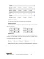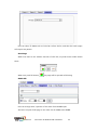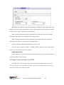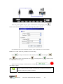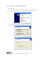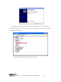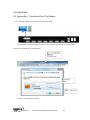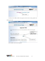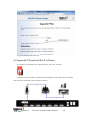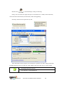
1
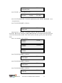
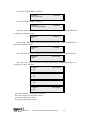
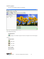
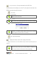
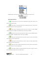
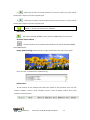
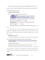
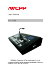
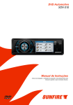
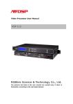
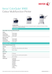
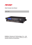
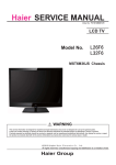
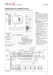
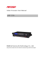
Video Processor User Manual
VSP 330
RGBlink Science & Technology Co., Ltd.
The pictures and data in the user manual are reference only, check the real object!
CONTACT US
Headquarter: S603 Weiye Building Torch Hi-Tech Industrial Development Zone Xiamen,Fujian
Province, P.R.C
Shenzhen office: Room A05, Floor 4, Building 24, Industry factory Nanshan Science &
Technology Park, Shenzhen, Guangdong Province, P.R.C
Tel: +86-592-5771197
Fax:+86-592-5771202
E-mail:[email protected]
http://www.rgblink.com
Revision
Format
Time
ECO#
Description
Principal
1.0
2010-12-31
0000
Lisa
1.1
2010-01-12
0001
Released
Based on the user manual, following
information has been added:
1. Connectors and connectivity;
2. PC software instructions;
3. Setup Communication by RS232
4. Setup Communication by USB
5. Download IP board software
Lisa
CONTENT
1.0
Connectors and connectivity................................................................................................1
1.1 Interface and control signal ............................................................................................1
2.0 Front Panel Operation..............................................................................................................2
3.0 VSP 330 Menu...........................................................................................................................4
4.0 Customer Quick Setup Guide ...............................................................................................13
5.0 PC control ................................................................................................................................14
6.0 Appendix .................................................................................................................................26
1.0 Connectors and connectivity
1.1 Interface and control signal
1. Small white push button, used only when upgrade the firmware;
2. Copper RJ45, used to connect the computer by 568B-568A twist-pair CAT5 cable;
3. USB interface,used to connect to the computer;
4. RS232 interface (RJ11), used to connect the computer;
5. HDMIA input interface. Input the signal from HD player, DVD, computer, and so on;
6. HDMIB input interface. Input the signal from HD player, DVD, computer, and so on;
7. HDMI LOOP OUT, used to loop input HDMI signal to next processor;
8~11.HDMI1~4, HDMI output connector;
Note:
HDMI1~4, DVI-I connector, HDMI1.3 compatible
12~13.Switch and Power
VSP 330
Document ID:RGB-RD-UM-V330C001
1
2.0 Front Panel Operation
Insert power cord and push power to ON position. LCD module on the front panel will
show RGBLINK and go into self verification before it load last setting configuration and
send processed image to the target monitor. For the first setup,CV1 input is default source.
With front panel keyboard, user can operate VSP with menu display on LCD module.
1、LCD Module: the menu to show
the switching between bottons and transmission.
2、Keyboard:
ESC: Push to exit from current selected item.
SEL: Push to confirm the current selected item
UP: Push to select item in up option;
DOWN: Push to select item in down option;
LEFT: Push to select left item;
RIGHT:Push to select right item;
HDMIA: Push to switch to HDMIA Input;
HDMIB: Push to switch to HDMIB Input
HDMI1: Push to HDMI1 output setting menu.
HDMI2: Push to HDMI2 output setting menu.
HDMI3: Push to HDMI3 output setting menu.
HDMI4: Push to HDMI4 output setting menu.
HDMI1~4 use standard DVI-I connector, which is compatible with HDMI
1.3, use HDMI to DVI cable to connect with HDMI source.
SAVE1: Switch to active user-defined mode1.
SAVE2: Switch to active user-defined mode2.
SAVE3: Switch to active user-defined mode3.
SAVE4: Switch to active user-defined mode4.
SAVE5:Switch to active user-defined mode5.
VSP 330
Document ID:RGB-RD-UM-V330C001
2
SAVE6: Switch to active user-defined mode6.
AB: Push to active seamless switch effects setting menu.
SCALE: Push to active HDMIA and HDMIB scale setting menu.
FRE: Push to freeze the video from live or live the video from freeze.
MENU: Push to go to main menu.
INF: Push to check the menu of input and output info, version and seriel NO.;
OUT: Push to active output format menu.
I/II: Push to set single picture mode or dual picture mode
SAVE: Push to go to save ready mode, and then push SAVE1、SAVE2、SAVE3、SAVE4、
SAVE5 or SAVE6 seperately will save the configuration.
Press
, Through mode, VSP 330 works in distribution mode.
Press
, Split input in Horizontal direction by zoom in input to 2 times, HDMI1
output is the same to HDMI3, and HDMI2 output is the same to HDMI 4.
Press
, Split input in Vertical direction by zoom in input to 2 times, HDMI1
output is the same to HDMI3, and HDMI2 output is the same to HDMI 4.
Press
, Split input in horizontal and vertical together with each 2 times, which
means each output 1/4 of the original input.
Press
, Split input in Horizontal direction by zoom in input to 4 times, which
means each output 1/4 of the original input.
Press
, Split input in Vertical direction by zoom in input to 4 times, which means
each output 1/4 of the original input.
VSP 330
Document ID:RGB-RD-UM-V330C001
3
3.0 VSP 330 Menu
After initial,system menu will show as following:
RGBLINK
视诚科技
亮彩系列
AVDSP Series VSP 330
Wait Init Network…
User can connect the device with LAN Network, If there is connection, VSP 330 will
get a auto allocated IP address directly.
IP Address
192.168.1.100
If there is no connection display will show DHCP Failed;
DHCP Failed
Push【MENU】button to access the main menu, as follow:
>VSP 330
*Dev Info
Recall
Touch 【LEFT】/【RIGHT】 button to select the left or right menu items. Before the
menu item, if there is a * sign, means the menu item has been selected, you can push the
SEL key to enter its sub menu.
in “Dev Info” menu. Select it to show the information bout the input signal.
Short Cut: Push the 【INF】button to get the Dev Info.
As following:
HDMIA:0X480X0
HDMIB:0X480X0
Push 【UP】/【DOWN】 to check the current format:
VSP 330
Document ID:RGB-RD-UM-V330C001
4
Output Format:
1024x768x60
Push 【UP】 /【DOWN】 to check the current version:
Software Version
1.0
Push 【UP】/【DOWN】 to get the serial-number,user can get more service and
support with the serial number.
RGBLINK
SN: 1234
Push 【LEFT】/【RIGHT】 button to select Recall, push SEL to do a Factory Reset; after
successful the menu shows:
Reset Finished
Push 【UP】/【DOWN】 button to select the sub menu, users can select to use English
as menu language and loop-out for HDMIA or HDMIB.
>VSP 330
*Language
Loop out
Push 【LEFT】/【RIGHT】button to select the sub menu of language as follow:
* Language Select
> English
中文
Push 【LEFT】/【RIGHT】button to select Loop out connection;
Push 【HDMIA】 or 【HDMIB】 button to get the video from loop out
connector directly.
Loop out Select
>HDMI A
HDMI B
Push 【UP】/【DOWN】 button to select the sub menu to set timer.
>VSP 330
*Time
Calendar
Push 【SEL】 button to go into Timer setting;
VSP 330
Document ID:RGB-RD-UM-V330C001
5
Time
> 00:00:20
Push 【LEFT】/【RIGHT】 to activate the timer setting,when the left line shows the
character*, means hour is editable, push UP/DOWN to change the minute or second;
Time
*00:00:20
Push 【SEL】 to enter Calendar setting; The date is shown on the left hand side, on the
right shows the Day of the Week.
Calendar
>2010/01/01
Sun
Push 【LEFT】/【RIGHT】 to activate date setting; When there appears the flashing
character* on the left of the date, current flashing parameter could be revised, push
UP/DOWN to adjust the date.
Time
*2010/01/01
Sun
Push 【UP】/【DOWN】 to enter the submenu AB Mode and Scale.
Push the 【AB】 button to enter seamless switch effects setting.
>VSP 330
* Scale
AB Mode
AB Mode including: full-screen switching, transparent full-screen switch, wipe off switch
and so on.
Push 【LEFT】【
/ RIGHT】 to select AB Mode, all available mode including: CUT Switch, Wipe
right shift, Wipe left shift, Wipe up shift, and Wipe down shift.
Setup AB Mode
> CUT Switch
Setup AB Mode
> DISSOVLE Switch
Push 【SEL】 to set fade in fade out duration time, press 【UP】/【DOWN】 to set seconds
which ranges from 0.5 s to 30.0 s.
VSP 330
Document ID:RGB-RD-UM-V330C001
6
Dissolve Duration:
>3.0 s
Push 【SEL】 to confirm, enter into WIPE HARD Switch.
Setup AB Mode
> WIPE HARD Switch
Setup AB Mode
> WIPE SOFT Switch
Push 【UP】/【DOWN】, there are several seamless switching modes as following:
WIPE Mode
> WIPE RIGHT
WIPE Mode
*WIPE LEFT
WIPE Mode
*WIPE DOWN
WIPE Mode
*WIPE UP
WIPE Mode
*WIPE PLUS OUT
WIPE Mode
*WIPE CURTAIN OUT
WIPE Mode
*WIPE CENTER OUT
VSP 330
Document ID:RGB-RD-UM-V330C001
7
Push 【SCALE】 to go into SCALE MENU:
Scale A Width:
>1024
Scale A Height:
>768
With PIP Picture in Picture mode, user can adjust X,Y position of sub picture, user can not
adjust X,Y position of the main picture.
VSP 330
Document ID:RGB-RD-UM-V330C001
8
Scale B Pos X:
>0
Scale B Pos Y:
>0
Push【LEFT】/【RIGHT】to set the value of coordinate X or Y;
Scale B Width:
>1024
Scale B Height:
>768
Push 【OUT】 to go into output formats menu, push 【UP】/【DOWN】 to find the right
output resolution which user may use, select 【HDMIA】,The output format would be the
same with HDMIA, use HDMIB, output format would be the same with HDMIB.
Output Format:
>HDMIA
Output Format:
>HDMIB
Push 【UP】/【DOWN】to find the resolution as shown:
Output Format:
>1024x768x60
Push 【PIP】 to enter picture in picture mode, press this button to display the two video
sources from HDMI1 and HDMI2:
Setup PIP mode
Finished!
The device supports total 6 user configuration modes, when press 【SAVE】 button,
【SAVE1】, 【SAVE2】, 【SAVE3】, 【SAVE4】, 【SAVE5】, 【SAVE6】 button will light
up together and the menu will shows:
Save Setting To:
Press ESC to Exit
Press 【SAVE1】 to save the current configuration to User Mode 1:
Save Setting To:
SAVE1
Finished!
After user mode 1 saved, User Mode 1 will be recalled after the device power on (User do
not make factory reset before that). Other user mode can be called if push the user mode
VSP 330
Document ID:RGB-RD-UM-V330C001
9
button separately.
Push 【HDMI1】、【HDMI2】、 【HDMI3】 or 【HDMI4】to each output setting menu:
>HDMI1
*TP Setup
XP Setup
Push【UP】/【DOWN】 shows:
>HDMI1
*DE Setup
Select TP Setup and push 【SEL】to go into TEST Pattern setting menu, TEST Pattern is used
to test monitor and signal stability:
>HDMI1
*ON
TP On/Off
Push 【UP】/【DOWN】to enable by ON or disable by Off of the TEST Pattern, select ON
and push 【SEL】 to enter into TEST Pattern, the device offers following TEST Pattern Mode:
standard horizontal and vertical color bar, horizontal and vertical gray scale, left rolling bar,
right rolling bar, up rolling bar and down rolling bar, left incline rolling bar, right incline
rolling bar.
>HDMI1
>Color Bar H
TP Mode
Then push 【UP】/【DOWN】, as follows:
>HDMI1
>Color Bar V
TP Mode
Push 【UP】/【DOWN】, as follows:
>HDMI1
>Gray Bar H
TP Mode
Push 【UP】/【DOWN】, as follows:
>HDMI1
> Gray Bar V
TP Mode
Push 【UP】/【DOWN】, as follows:
>HDMI1
>Auto Color
TP Mode
Push 【UP】/【DOWN】 to go into Manual Color to change display color manually:
VSP 330
Document ID:RGB-RD-UM-V330C001
10
>HDMI1
>Manual Color
TP Mode
Push 【SEL】 to go into Manual Color:
>HDMI1
>R:000
G:000
TP Color
B:000
Push 【LEFT】/【RIGHT】 to chose the parameters, push 【UP】/【DOWN】 to set
the parameters:
Push 【UP】/【DOWN】, as follows
>HDMI1
>Roll Left
TP Mode
Select Roll Left、Roll Right、Roll down、Roll Up、Roll Up Left or Roll Down Right.
Push【SEL 】to set the rolling bar, push【UP】
【
/ DOWN】to set background and foreground
colors; The device offers total 8 colors: white, yellow, sky blue, green, pink, red, blue and
black.
Here is an example: select roll left
>HDMI1
>Yellow
TP Roll
>HDMI1
>Yellow
TP Back
>HDMI1
>Yellow
TP Fore
Push 【UP】/【DOWN】, as follows
>HDMI1
>Roll Right
TP Mode
Push 【UP】/【DOWN】, as follows
>HDMI1
>Roll Down
TP Mode
Push 【UP】/【DOWN】, as follows
>HDMI1
>Roll Up
VSP 330
TP Mode
Document ID:RGB-RD-UM-V330C001
11
Push 【UP】/【DOWN】, as follows
>HDMI1
>Roll Up Left
TP Mode
Push 【UP】/【DOWN】, as follows
>HDMI1
>Roll Down Right
TP Mode
Select XP Setup and press 【SEL】 to set horizontal position, push【LEFT】/【RIGHT】
to adjust the parameter value:
>HDMI1
*23
X Setup
Push 【UP】/【DOWN】, enter vertical position setting, push 【LEFT】/【RIGHT】 to
adjust the parameter value:
>HDMI1
*23
Y Setup
Select DE Setup to adjust image offset, push 【SEL】, DE image offset could be adjusted:
>HDMI1
*ON
DE On/Off
Select ON to go into DE setting menu, push【UP】/【DOWN】, 【LEFT】/【RIGHT】 to set
the parameter value, as follows
>HDMI1
> 35
DE H Start
>HDMI1
> 35
DE V Start
>HDMI1
> 35
DE Width
>HDMI1
> 35
DE Height
DE H Start: Image horizontal position setting;
DE V Start: Image vertical position setting;
DE Width: Image width setting;
DE Height: Image height setting;
VSP 330
Document ID:RGB-RD-UM-V330C001
12
4.0 Customer Quick Setup Guide
1.
Turn off the device;
2.
According to project requirements, connect the necessary inputs and outputs, for the
cascade of other DVI device, use the cascade interface;
3.
Power on the device
4.
Choose the output format
5.
Choose AB push effect
6.
Select input channel
7.
Select work mode
8.
Set size and position of every output
VSP 330
Document ID:RGB-RD-UM-V330C001
13
5.0 PC control
VSP 330 control software interface is as following:
5.1 Software Introduce.
Language Option.
Language. The software supports Chinese and English version with language
selected.
Communication.
Open COM.
Close COM.
: Set COM.
Device toolbar
Synchronization.
VSP 330
Document ID:RGB-RD-UM-V330C001
14
: Click “Synchronization”, Can sync the data from the VSP 330 in
communication to the software run on the PC, at the same time the data in the
EPROM can synchronize with the device.
: Save to flash.
: Load from flash.
There are 6 user save modes.
:Factory reset
Click “Factory setup”, previously saved user-mode will be cleared
: Advance, for administrator control.
”Advance” for engineer specially, please contact with our Customer
Service engineer to get the code if it is necessary.
Help
:Help.. Display helps dialogue.
About.
: Display the software version and company information;
Output resolution:User can choose different output resolution by selecting from pull
down list.
Click the drop-down arrow to select HDMIA or HDMIB, then
the output resolution is the same to them seperately;
VSP 330
Document ID:RGB-RD-UM-V330C001
15
HDMI resolution: show the current HDMIA and HDMIB input resolution info.
Split mode of VSP 330
1.
,Through mode, VSP 330 works in distribution mode. Each output is the
same to current input mode;
2.
,Split input in horizontal and vertical together with each 2 times, which
means each output 1/4 of the original input.
3.
,Split input in Horizontal direction by zoom in input to 2 times, HDMI1
output is the same to HDMI3, and HDMI2 output is the same to HDMI 4.
4.
,Split input in Vertical direction by zoom in input to 2 times, HDMI1 output is
the same to HDMI3, and HDMI2 output is the same to HDMI 4.
5.
,Split input in Horizontal direction by zoom in input to 4 times, which means
each output 1/4 of the original input.
6.
,Split input in Vertical direction by zoom in input to 4 times, which means
each output 1/4 of the original input.
7.
,Split input in up 1/2 Horizontal direction by zoom in input to 4 times, which
means each output 1/8 of the original input.
8.
,Split input in down 1/2 Horizontal direction by zoom in input to 4 times,
which means each output 1/8 of the original input.
VSP 330
Document ID:RGB-RD-UM-V330C001
16
9.
,Split input in left 1/2 Vertical direction by zoom in input to 4 times, which
means each output 1/8 of the original input.
10.
,Split input in right 1/2 Vertical direction by zoom in input to 4 times, which
means each output 1/8 of the original input.
Mode 7~10 only can be active by software.
PIP Toolbar
: PIP mode; Defaultly HDMIA is main picture, HDMIB input is sub picture.
Seamless switch effects
: Click this button to set seamless switch effects for switch between HDMIA
and HDMIB inputs.
Image Split Drawing: shows the split images mode when the split button push.
User can save or delete all the operation log.
Information :
At the bottom of the software will show the model of the processor, here ise VSP
330,the software version, front firmware version, back firmware version and serial
number of the processor.
VSP 330
Document ID:RGB-RD-UM-V330C001
17
There are two system function pages, one is DVID4P which used to set
function on split mode; GOOD page is used to set advance function like PIP,
seamless switch effects and so on.
DVID4P: System Status Page
User can check current split mode and system status.
The Screen Mode is used for the user to check which split mode current VSP 330
works;
The System Status has two status, one is DDR initialization, which is used to
check
whether VSP 330 hardware is working in normal status. It is normal when check; Video
Input is used to check whether input signal from HDMIA or HDMIB is correct. It is correct
when checked.
DVID4P: System Control
There are two working modes for each output, one is Normal mode to output video
which processed from inputs, Test Mode is used to output test pattern;
Straight function used to set each output as the same to the input.
The following in the pages are used to set each channel output video. For example, If
user push Channel2 for Channel1, it means HDMI1 output video the same to HDMI2. If
user check Straight, means HDMI1 output normal video which distribute default by the
software.
VSP 330
Document ID:RGB-RD-UM-V330C001
18
DVID4P: Video Module
This page is used to test now, not comments to do any modification.
DVID4P: DDR Module
Only comments user to change the X,Y position for each output, to meet processed
video area requirement.
DVD4P: Pattern
This is the page used to set test pattern output for each output, user check Pattern 1
means user will control HDMI1 output as test pattern. And Pattern2 is for HDMI2, Pattern
3 is for HDMI 3 and Pattern 4 is for HDMI4.
When user check the Pattern 1 to Pattern 4, the following page will be opened at the
same time.
VSP 330
Document ID:RGB-RD-UM-V330C001
19
User can select TP Mode such as Color Bar H from the list, and then the each output
will output test pattern.
Good Page
When user want to use advance function of VSP 330, can push button under GOOD
block.
When user push PIP button
, the page will be opened as following.
GOOD-PIP
User can change the X,Y position of the video from HDMIB input.
And user can push Scale page to set video size of HDMIA and HDMIB.
VSP 330
Document ID:RGB-RD-UM-V330C001
20
For the parameters Video Width and Video Height inside ScaleA and ScaleB, they are
used for further function, it is not use to change the value now.
User can change the value of Output Width and Output Height inside EScaler, after
user change the value, should push “Set” button to active.
And user can change the video size by plug image on the right.
When user push AB button
, will open page as following, which is also inside
Image Fun page, but change from PIP to Alpha.
VSP 330
Document ID:RGB-RD-UM-V330C001
21
【Alpha】:the equipment provide six seamless switching mode, image right shift,
image moves left, image moves down, image upshifting and image fluctuation to move,
image center to center around move on both sides
When opening [transparent switch], equipment provided with 6 kinds of seamless
switching mode switch has a transparent soft change effect;
When closing [transparent switch], equipment provided with 6 kinds of seamless
switching mode switch no transparent soft change effect
【fade in fade out time switch】range from 0.5s to 30.0s;
Click the option PORTA→PORTB or PORTB→PORTA,during the two video inputs
switch, user will find the effects they choose.
GOOD-Auto Config
If user push button, VSP 330 will auto set the parameters, which is the same function
to the front panel “Freeze” button.
5.2 Setup Communication by RS232
Use DB9 to RJ11 cable to control VSP 330 by its RS 232 port. DB9 should connect to PC
com port or another device which has the com port; RJ11 port should connect to RS 232 port on
VSP 330. As shown of the following picture.
VSP 330
Document ID:RGB-RD-UM-V330C001
22
After user get the right RS 232 port, open communication setting page by push
button under Communication part, and the following dialog will be opened.
User should use the same CommPort to the PC or the control device in used, and use
Baudrate as 115200. After that, push OK to close the dialog.
Push
push
to setup communication with VSP 330, and
will close the communication and
will change to
will change back to
, which is ready
for setup communication again.
After success of setting up communication, it will show
, and
will change to green.
If user could not success to make communication, should check whether the
com part took place by another software.
VSP 330
Document ID:RGB-RD-UM-V330C001
,
23
5.3
How to use a USB connection PC?
1.Install the driver
Connect USB cable to VSP 330, another end to PC or laptop, power on VSP 330. For the first
time to use the PC or laptop for VSP 330, it will ask for install the driver as following.
Choose from the list or the location of the USB driver, click "next" to continue.
VSP 330
Document ID:RGB-RD-UM-V330C001
24
After install is finished, user will find the PC detect this USB device, and will allocate a
COM port the USB. User can find this port inside device management of the system, which show
as MCB2300 USB VCom port.
Setup with USB communication is the same to RS 232.
VSP 330
Document ID:RGB-RD-UM-V330C001
25
6.0 Appendix
6.1 AppendixⅠ Download the IP software
1. First, connect the device with PC by network cable
2. Input VSP 330 network address in address bar: 192.168.0.100, enter the user name admin
and password rgblink123 in the dialog box
3. Thirdly, click on FPGA Upgrade:
VSP 330
Document ID:RGB-RD-UM-V330C001
26
4. Fourthly, click on【browse】to select upgrade, file name must be Preamp_FPGA.bin or
Bakamp_FPGA.bin.
Click Send】to send and wait for upgrade
VSP 330
Document ID:RGB-RD-UM-V330C001
27
6. Upgrade Bakamp FPGA Success
6.2 Appendix II Download the IP software
Turn off the power, take the two coding switch to “ON” sate. As below:
Connect one side of the RJ11 download line to the RS232 on the video processor,and the
other side to be connected to the serial port on the PC.
VSP 330
Document ID:RGB-RD-UM-V330C001
28
Double click
to run Flash Magic, setting as following:
Firstly, users can choose the right serial port, set the baud rate to 115200, choose LPC2368,
and to load the aim document (hex.document) of IP board upgrading.
Secondly, confirm the two option box by tick.
Finally, click the “Start” button.
After download, exit the program, turn off the power, push the two white coding switch back
to default position. Power on VSP 330, check whether VSP 330 works well as version control.
Flash Magic download website:
http://rgblink.cn/_d269804420.htm
VSP 330
Document ID:RGB-RD-UM-V330C001
29