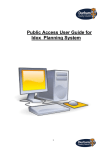
1
User Manual AMAX-1220/1240 Series Open Frame 2/4-Axis AMONet RS-485 Motion Slave Modules Copyright The documentation and the software included with this product are copyrighted 2012 by Advantech Co., Ltd. All rights are reserved. Advantech Co., Ltd. reserves the right to make improvements in the products described in this manual at any time without notice. No part of this manual may be reproduced, copied, translated or transmitted in any form or by any means without the prior written permission of Advantech Co., Ltd. Information provided in this manual is intended to be accurate and reliable. However, Advantech Co., Ltd. assumes no responsibility for its use, nor for any infringements of the rights of third parties, which may result from its use. Acknowledgements AMONet and AMAX-1220/1240 are trademarks of Advantech Inc. Intel and Pentium are trademarks of Intel Corporation. Microsoft Windows and MS-DOS are registered trademarks of Microsoft Corp. All other product names or trademarks are properties of their respective owners. Product Warranty (2 years) Advantech warrants to you, the original purchaser, that each of its products will be free from defects in materials and workmanship for two years from the date of purchase. This warranty does not apply to any products which have been repaired or altered by persons other than repair personnel authorized by Advantech, or which have been subject to misuse, abuse, accident or improper installation. Advantech assumes no liability under the terms of this warranty as a consequence of such events. Because of Advantech’s high quality-control standards and rigorous testing, most of our customers never need to use our repair service. If an Advantech product is defective, it will be repaired or replaced at no charge during the warranty period. For outof-warranty repairs, you will be billed according to the cost of replacement materials, service time and freight. Please consult your dealer for more details. If you think you have a defective product, follow these steps: 1. Collect all the information about the problem encountered. (For example, CPU speed, Advantech products used, other hardware and software used, etc.) Note anything abnormal and list any onscreen messages you get when the problem occurs. 2. Call your dealer and describe the problem. Please have your manual, product, and any helpful information readily available. 3. If your product is diagnosed as defective, obtain an RMA (return merchandize authorization) number from your dealer. This allows us to process your return more quickly. 4. Carefully pack the defective product, a fully-completed Repair and Replacement Order Card and a photocopy proof of purchase date (such as your sales receipt) in a shippable container. A product returned without proof of the purchase date is not eligible for warranty service. 5. Write the RMA number visibly on the outside of the package and ship it prepaid to your dealer. Part No. 20032A0000 Edition 1 Printed in Taiwan January 2013 AMAX-1220/1240 Series User Manual ii Declaration of Conformity CE This product has passed the CE test for environmental specifications when shielded cables are used for external wiring. We recommend the use of shielded cables. This kind of cable is available from Advantech. Please contact your local supplier for ordering information. Technical Support and Assistance 1. 2. Visit the Advantech web site at www.advantech.com/support where you can find the latest information about the product. Contact your distributor, sales representative, or Advantech's customer service center for technical support if you need additional assistance. Please have the following information ready before you call: – Product name and serial number – Description of your peripheral attachments – Description of your software (operating system, version, application software, etc.) – A complete description of the problem – The exact wording of any error messages Packing List Before setting up the system, check that the items listed below are included and in good condition. If any item does not accord with the table, please contact your dealer immediately. In addition to this User Manual, the package should also include the following items: AMAX-1220/1240 Series: Open Frame Type 2/4-Axis AMONet RS-485 Motion Slave Modules iii AMAX-1220/1240 Series User Manual AMAX-1220/1240 Series User Manual iv Contents Chapter 1 Introduction..........................................1 1.1 1.2 Features .................................................................................................... 2 AMAX-1220 Specification ......................................................................... 2 1.2.1 Axes .............................................................................................. 2 1.2.2 Encoder input................................................................................ 3 1.2.3 Pulse/Direction output................................................................... 3 1.2.4 Digital input ................................................................................... 3 1.2.5 Digital output ................................................................................. 3 1.2.6 Simultaneous move signal ............................................................ 4 1.2.7 General Specification.................................................................... 4 AMAX-1240 Specification ......................................................................... 5 1.3.1 Axes .............................................................................................. 5 1.3.2 Encoder input................................................................................ 5 1.3.3 Pulse/Direction output................................................................... 5 1.3.4 Digital input ................................................................................... 6 1.3.5 Digital output ................................................................................. 6 1.3.6 Simultaneous move signal ............................................................ 6 1.3.7 General Specification.................................................................... 7 1.3 Chapter 2 Hardware Functionality .......................9 2.1 PCB Board Layout .................................................................................. 10 2.1.1 AMAX-1220 PCB Layout & Pin Assignment ............................... 10 Figure 2.1 PCB Layout of AMAX-1220 ...................................... 10 Figure 2.2 Top View of AMAX-1220 .......................................... 11 Figure 2.3 Middle View of AMAX-1220...................................... 11 Figure 2.4 Bottom View of AMAX-1220 ..................................... 12 Figure 2.5 Side View of AMAX-1220 ......................................... 12 2.1.2 AMAX-1240 Label Assignment ................................................... 14 Figure 2.6 PCB Layout of the AMAX-1240 L2 ........................... 14 Figure 2.7 Top View of AMAX-1240 L2 ..................................... 15 Figure 2.8 Middle View of AMAX-1240 L2................................. 15 Figure 2.9 Bottom View of AMAX-1240 L2 ................................ 16 Figure 2.10Side View of AMAX-1240 L2 .................................... 16 Power Connector .................................................................................... 18 2.2.1 Module Power Connector (CN1)................................................. 18 Table 2.1: Module Power Connector (CN1) .............................. 18 2.2.2 External Power Connector (CN2) ............................................... 18 Table 2.2: External Power Connector (CN2) ............................. 18 AMONet Interface ................................................................................... 19 2.3.1 AMONet Extension ..................................................................... 19 Table 2.3: AMONet Extension ................................................... 19 Figure 2.11RS-485 Extension Port ............................................. 19 2.3.2 Terminal Resistor........................................................................ 20 Table 2.4: Terminal Resistor ..................................................... 20 Board ID Setting (SW1)........................................................................... 20 Table 2.5: Board ID Setting (SW1) ............................................ 20 Communication Protocol Baud Rate Setting (SW2)................................ 21 2.5.1 Baud-Rate Setting....................................................................... 21 2.5.2 TUD............................................................................................. 21 2.5.3 TMD ............................................................................................ 21 2.5.4 EMG............................................................................................ 21 End Limit Logic Setting (SW3) ................................................................ 22 LED Definition ......................................................................................... 22 2.2 2.3 2.4 2.5 2.6 2.7 v AMAX-1220/1240 Series User Manual 2.8 2.9 Motion Control Connector Pin Definition (CN3 to CN9) .......................... 23 2.8.1 External Power Connection and Simultaneous Move Signal (CN3) 23 Table 2.6: External Power Connection and Simultaneous Move Signal (CN3)............................................................. 23 2.8.2 Servo Drive Interface .................................................................. 23 Table 2.7: Servo Drive Interface................................................ 24 2.8.3 Mechanical I/O Interface............................................................. 25 2.8.4 Extra General Purpose Input & Output (ONLY available for AMAX1220 model)................................................................................ 26 Table 2.8: CN4 .......................................................................... 26 Table 2.9: CN5 .......................................................................... 26 Motion Signal Connection ....................................................................... 27 2.9.1 Digital Input................................................................................. 27 Table 2.10: ORG Pins ................................................................. 27 Table 2.11: LMT+ and LMT- Pins................................................ 27 Table 2.12: LTC Pins................................................................... 27 Table 2.13: SD Pins .................................................................... 27 Table 2.14: ALM Pins .................................................................. 27 Table 2.15: INP Pins ................................................................... 28 Table 2.16: RDY Pins.................................................................. 28 Table 2.17: EMG Pins ................................................................. 28 2.9.2 Digital Output .............................................................................. 28 Table 2.18: CMP Pins ................................................................. 28 Table 2.19: BREAK Pins ............................................................. 28 Table 2.20: SVON Pins ............................................................... 29 Table 2.21: ERC Pins.................................................................. 29 Table 2.22: RALM Pins ............................................................... 29 2.9.3 Digital Bi-direction Simultaneously Move Signal......................... 29 Table 2.23: CSTA Pins................................................................ 30 Table 2.24: CSTP Pins................................................................ 30 2.9.4 Pulse Output Signal .................................................................... 31 Table 2.25: DDA Pulse Pins........................................................ 31 Table 2.26: Encoder Pins ............................................................ 31 2.9.5 Extra General Purpose Input & Output (ONLY available for AMAX1220 model)................................................................................ 31 Table 2.27: IDIx Pins ................................................................... 31 Table 2.28: IDOx Pins ................................................................. 32 AMAX-1220/1240 Series User Manual vi Chapter 1 1 Introduction This chapter gives an overview of the product features, and specifications for AMAX-1220/1240 Series. Sections include: Features Specifications Products in the AMAX-1220/1240 Series are used to increase the number of axes for an AMONet RS-485 distributed motion control network. These extension slave modules connect serially by a simple and affordable Cat.5 LAN cable, reducing the wiring between driver and controller. This is very suitable for highly integrated machine automation applications. AMAX-1220 and AMAX-1240 support a range of common motor vendors by transfer cable, such as Mitsubishi J3-Super series, Panasonic Minas A4 or A5 type, and Yaskawa Sigma-V. 1.1 Features End limit logic is switchable (high or low active) Board ID is switchable Easily visible LED indicators on board to do diagnosis Direct wire to servo drive to save terminal board space while installation Max. 6.5 MHz, 4-axis pulse output 28 bits counter for incremental encoder Horizontal installation for for servo or stepping motor driver Suitable for DIN-rail mounting Linear & Circular interpolation support for AMAX-1220/1240 Simultaneously start / stop between modules are supported for AMAX-1220 and AMAX-1240 Position compare and triggering function is supported for AMAX-1240 by linear interval & table list method 1.2 AMAX-1220 Specification 1.2.1 Axes Number of Axes 2 Axes Driver Output Pulse Position control Range -134,217,728 ~ +134,217,728 Acceleration/ Deceleration 1 to 65,536(16-bits) Driver Speed Max: 5 Mpps Min: 0.1 pps Pulse Output Type Pulse/Direction(1-pulse, 1-direction type) or Up/ Down(2-pulse type) or A/B phase Counter Counter1: Command position counter Counter2: Mechanical position counter Counter3: General-purpose deviation counter Precision 0.5LSB Output Signal Modes Differential line driving output Speed Curve T/S-curve Acceleration/Deceleration Range 2~32-Axes Linear Speed Interpolation Precision 2-Axes Circular Interpolation -134,217,728 ~ +134,217,728 0.1~5Mpps 0.5LSB Range -134,217,728~+134,217,728 Speed 0.1~5Mpps Precision 0.5LSB AMAX-1220/1240 Series User Manual 2 Item Description Type ECA ECB ECZ Two terminal, opto-isolated Quadrature (A/B phase) or Up/Down (CW/CCW) Input voltage 0: (V+ - V-) < 1VDC 1: (V+ - V-) > 3.5VDC Max. input voltage |V+ - V-| < 15VDC Max. input frequency 3MHz x1, x2, x4 (A/B phase only) Protection 2,500V Isolation 1.2.3 Pulse/Direction output Item CW\PULS CCW\DIR Description Type Two terminal, opto-isolated Output voltage 0~4V Max. output voltage 4 VDC (1: min 2VDC, 0: MAX 0.7VDC) The output voltage will drop depend on the output current Max. output frequency 5MHz 1.2.4 Digital input Item Description ORG LMT+, LMTINPOS ALM RDY LTC SD DI0 - DI7 Type One terminal, opto-isolated Input voltage 0: Vin < 3VDC 1: Vin > 10VDC Input Current 4.2 mA @ 24 V Max. Input voltage 30 VDC Max. Input delay time 100 µs Protection 2,500 V Isolation 1.2.5 Digital output Item BREAK ALMCLR SRVON ERC COMP DO0 - DO7 Description Type One terminal, opto-isolated, Current sink (5 ~ 30 V) Output voltage 0: Vo < 0.8 VDC 1: Vo <= Vio Max. output voltage 30 VDC Max. sink current 200 mA per channel Max. Output delay time 100 µs (BREAK, ALMCLR, SRVON, ERC) 250 µs (DO0 - DO7) Protection 2,500 V Isolation 3 AMAX-1220/1240 Series User Manual Introduction Encoder Pulse Input Type Chapter 1 1.2.2 Encoder input 1.2.6 Simultaneous move signal Item CSTA CSTP Description Type One terminal, opto-isolated, Current sink (5 ~ 30 V) Output voltage 0: Vo < 0.8 VDC 1: Vo <= Vio Max. output voltage 30 VDC Max. sink current 200 mA per channel Max. Output delay time 1 µs Protection 2,500 V Isolation 1.2.7 General Specification Item Description Bus Type AMONet RS-485 Certifications CE, FCC Class A I/O Connector Type 2*DB26+2*9 pin pluggable connector 2*12 pin pluggable connector Dimensions 142 x 104 x 45 mm (5.6" x 4.1" x 1.8”) Power Consumption Typical 65 mA @ 24 V Max 75 mA @ 24 V System Power Supply VS: 24 VDC ± 10% Power Supply for Digital Input/ Output VEX: 10-30 VDC Storage Humidity 5~95% RH, non-condensing Operating Temperature 0 ~ 65°C Storage Temperature -25 ~ 85°C AMAX-1220/1240 Series User Manual 4 Chapter 1 1.3 AMAX-1240 Specification 1.3.1 Axes Number of Axes 4 Axes Position control Range -134,217,728 ~ +134,217,728 Acceleration/ Deceleration 1 to 65,536 (16-bits) Max: 6.5Mpps Min: 0.1 pps Pulse Output Type Pulse/Direction (1-pulse, 1-direction type) or Up/Down (2-pulse type) or A/B phase Counter Counter1: Command position counter Counter2: Mechanical position counter Counter3: Deflection counter Precision 0.5LSB Output Signal modes Differential line driving output Speed Curve T/S-curve Acceleration/Deceleration 2~4-Axes Linear Interpolation Range -134,217,728 ~ +134,217,728 Speed 0.1 ~ 6.5 Mpps Precision 0.5 LSB 2-Axes Circular Interpolation Range -134,217,728 ~ +134,217,728 Speed 0.1 ~ 6.5 Mpps Precision 0.5 LSB 1.3.2 Encoder input Item ECA ECB ECZ Description Type Two terminal, opto-isolated Encoder Pulse Input Type Quadrature (A/B phase) or Up/Down (CW/CCW) Input voltage 0 (V+ - V-) < 1 VDC 1: (V+ - V-) > 3.5 VDC Max. input voltage |V+ - V-| < 15 VDC Max. input frequency 3 MHz x1, x2, x4 (A/B phase only) Protection 2,500 V Isolation 1.3.3 Pulse/Direction output Item CW\PULS CCW\DIR Description Type Two terminal, opto-isolated Output voltage 0~4V Max. output voltage 4 VDC (1: min 2 VDC, 0 MAX 0.7 VDC) The output voltage will drop depend on the output current Max. output frequency 6.5 MHz 5 AMAX-1220/1240 Series User Manual Introduction Driver Output Pulse Driver Speed 1.3.4 Digital input Item ORG LMT+, LMTINPOS ALM RDY LTC SD Description Type One terminal, opto-isolated Input voltage 0: Vin < 3 VDC 1: Vin > 10 VDC Input Current 4.2 mA @ 24 V Max. Input voltage 30 VDC Max. Input delay time 100 µs Protection 2,500 V Isolation 1.3.5 Digital output Item BREAK ALMCLR SRVON ERC COMP Description Type One terminal, opto-isolated, Current sink (5 ~ 30 V) Output voltage 0: Vo < 0.8 VDC 1: Vo <= Vio Max. output voltage 30 VDC Max. sink current 200 mA per channel Max. Output delay time 1 µs for COMP. 100 µs for BREAK, ALMCLR, SRVON, ERC. Protection 2,500 V Isolation 1.3.6 Simultaneous move signal Item CSTA CSTP Description Type One terminal, opto-isolated, Current sink (5 ~ 30 V) Output voltage 0: Vo < 0.8 VDC 1: Vo <= Vio Max. output voltage 30 VDC Max. sink current 200 mA per channel Max. Output delay time 1 µs Protection 2,500 V Isolation AMAX-1220/1240 Series User Manual 6 Item Description Bus Type AMONet RS-485 Certifications CE, FCC Class A I/O Connector Type 4*DB26+2*16pin pluggable connector Dimensions 142 x 104 x 45 mm (5.6" x 4.1" x 1.8”) Typical 75mA @ 24V Max 80mA @ 24V System Power Supply VS: 24 VDC ± 10% Power Supply for Digital Input/ Output VEX: 10-30 VDC Storage Humidity 5~95% RH, non-condensing Operating Temperature 0 ~ 65°C Storage Temperature -25 ~ 85°C 7 AMAX-1220/1240 Series User Manual Introduction Power Consumption Chapter 1 1.3.7 General Specification AMAX-1220/1240 Series User Manual 8 Chapter 2 2 Hardware Functionality This chapter shows the hardware functionality of AMAX-1220/1240 Series. Sections include: PCB Board Layout Power Connector AMONet Interface BoardID Switch Configuration Setting LED Definition Pin Definition Signal Connection Field Wiring Considerations 2.1 PCB Board Layout 2.1.1 AMAX-1220 PCB Layout & Pin Assignment Figure 2.1 PCB Layout of AMAX-1220 AMAX-1220/1240 Series User Manual 10 Chapter 2 Hardware Functionality Figure 2.2 Top View of AMAX-1220 Figure 2.3 Middle View of AMAX-1220 11 AMAX-1220/1240 Series User Manual Note! The height does not include the male connector. The height of male connector is 9mm Figure 2.4 Bottom View of AMAX-1220 Figure 2.5 Side View of AMAX-1220 AMAX-1220/1240 Series User Manual 12 Chapter 2 For Connectors Description CN1 Module Power CN2 External Power and EMG Input CN3 Sharing External Power and CSTA, CSTP Input CN4 12 pin pluggable connector CN5 12 pin pluggable connector CN6 DB26 Connector for X axis CN7 DB26 Connector for Y axis CN8 9 pin pluggable connector for X axis CN9 9 pin pluggable connector for Y axis SW1 Board ID Switch SW2 Configuration Setting SW3 Configuration Setting For LED indicators Name Description PWR Power LED RUN Communication LED EMG Emergency Stop LED STS Communication Status LED BSY Busy LED for n Axis ORG Origin LED for n Axis SON Servo On LED for n Axis LMT- Negative End Limit LED for n Axis ALM Alarm LED for n Axis LMT+ Positive End Limit LED for n Axis 13 AMAX-1220/1240 Series User Manual Hardware Functionality Name 2.1.2 AMAX-1240 Label Assignment Figure 2.6 PCB Layout of the AMAX-1240 L2 AMAX-1220/1240 Series User Manual 14 Chapter 2 Hardware Functionality Figure 2.7 Top View of AMAX-1240 L2 Figure 2.8 Middle View of AMAX-1240 L2 15 AMAX-1220/1240 Series User Manual Note! The height does not include the male connector. The height of male connector is 9mm Figure 2.9 Bottom View of AMAX-1240 L2 Figure 2.10 Side View of AMAX-1240 L2 AMAX-1220/1240 Series User Manual 16 Chapter 2 For Connectors Description CN1 Module Power CN2 External Power and EMG Input CN3 Sharing External Power and CSTA, CSTP Input CN4 DB26 Connector for X axis CN5 DB26 Connector for Y axis CN6 DB26 Connector for Z axis CN7 DB26 Connector for U axis CN8 16 pin pluggable connector for X and Y axis CN9 16 pin pluggable connector for Z and U axis SW1 Board ID Switch SW2 Configuration Setting SW3 Configuration Setting For LED indicators Name Description PWR Power LED RUN Communication LED EMG Emergency Stop LED STS Communication Status LED BSY Busy LED for n Axis ORG Origin LED for n Axis SVON Servo On LED for n Axis LMT- Negative End Limit LED for n Axis ALM Alarm LED for n Axis LMT+ Positive End Limit LED for n Axis 17 AMAX-1220/1240 Series User Manual Hardware Functionality Name 2.2 Power Connector 2.2.1 Module Power Connector (CN1) Table 2.1: Module Power Connector (CN1) Pin Name Type Pin description 1 +VS Power +24V power input 2 -VS Power Power ground 3 VE_GND Power External earth ground 2.2.2 External Power Connector (CN2) Table 2.2: External Power Connector (CN2) Pin Name Type Pin description 1 +VEX Power External +24V power input 2 -VEX Power External power ground 3 EMG In Isolated digital input 4 VE_GND Power External earth ground AMAX-1220/1240 Series User Manual 18 Chapter 2 2.3 AMONet Interface 2.3.1 AMONet Extension Pin Label Description 1 FG Field Ground 2 FG Field Ground 3 RS485+ High Speed RS-485 protocol 4 FG Field Ground 5 FG Field Ground 6 RS485- High Speed RS-485 protocol 7 FG Field Ground 8 FG Field Ground Figure 2.11 RS-485 Extension Port 19 AMAX-1220/1240 Series User Manual Hardware Functionality Table 2.3: AMONet Extension 2.3.2 Terminal Resistor Table 2.4: Terminal Resistor PIN 100 1/4W Resistor Note! 3 6 Terminal Resistor is used for the last module only. 2.4 Board ID Setting (SW1) SW1 is used to assign the ID occupation in network. AMAX-1240 will ONLY occupy 1 ID by node number setting, but AMAX-1220 will occupy 4 consecutive ID by node number setting. Take AMAX-1240 as example. If Pin 1 to Pin 4 are OFF, but Pin 5 & 6 are ON, the node number is 3. Then, AMAX-1240 board ID is 3 and only occupies this address. Take AMAX-1220 as example. If Pin 1 to 3 are OFF, but Pin 4 is ON, the node number is 4 (Please see Note 2). Then, AMAX-1220 board ID will occupy 4,5,6,7 as consecutive sequence. Other AMAX device shall avoid to occupy these 4 board ID. Assume your system uses one AMAX-1220 and one AMAX-1240. And, your node number is assigned as the above case. Then, the ID occupation would be 3,4,5,6,7, and the other ID would be empty for other AMAX devices. Table 2.5: Board ID Setting (SW1) Pin Label ON OFF 1 DN5 1 0 2 DN4 1 0 3 DN3 1 0 4 DN2 1 0 5 DN1 1 0 6 DN0 1 0 Note 1! Node Number=32xDN5+16xDN4+8xDN3+4xDN2+2xDN1+DN0. Default Setting: All the switches are in OFF status. AMAX-1240 needs 6 digits to set up the board ID. Note 2! AMAX-1220 ONLY needs first 4 pins to set up the board ID. Shortly, pin 5 and pin 6 ARE NOT available to use. Only use pin 1 to 4 to set up. AMAX-1220/1240 Series User Manual 20 Label Description 1 SPD1 Baud-Rate Setting 2 SPD0 3 TUD Time-Out Status Latch 4 TMD Specify watchdog timer time 5 BRK *For internal use only, please keep in OFF 6 EMG Emergency stop control Hardware Functionality Swtich 2.5.1 Baud-Rate Setting SPD1 SPD0 OFF OFF 20 MHz OFF ON 10 MHz ON OFF 5 MHz ON ON 2.5 MHz 2.5.2 TUD This terminal is used to set output conditions when the watchdog timer times out. OFF The output keeps its current status. ON The output is Reset. 2.5.3 TMD When the interval between data packets sent from a master card (ex. PCI-1202U) is longer than the specified interval, the watchdog timer times out. 20 Mbps 10 Mbps 5 Mbps 2.5 Mbps OFF 20 ms 40 ms 80 ms 160 ms ON 5 ms 10 ms 20 ms 40 ms 2.5.4 EMG This terminal is used to set input conditions when the emergency stops occurrence. OFF High active ON Low active. 21 Chapter 2 2.5 Communication Protocol Baud Rate Setting (SW2) AMAX-1220/1240 Series User Manual 2.6 End Limit Logic Setting (SW3) For AMAX-1220 Pin Name Type Pin description 1 ELLX IN ON: High active OFF: Low active 2 ELLY IN ON: High active OFF: Low active 3 NC 4 NC Type Pin description For AMAX-1240 Pin Name 1 ELLX IN ON: High active OFF: Low active 2 ELLY IN ON: High active OFF: Low active 3 ELLZ IN ON: High active OFF: Low active 4 ELLU IN ON: High active OFF: Low active 2.7 LED Definition For AMAX-1220 & AMAX-1240 Name Axis Pin Description PWR Power RUN Communication STS Communication Status EMG Emergency Stop BSY ALL Busy status for n Axis ORG ALL Origin status for n Axis SVON ALL Servo On status for n Axis LMT- ALL Negative End Limit status for n Axis ALM ALL Alarm status for n Axis LMT+ ALL Positive End Limit status for n Axis AMAX-1220/1240 Series User Manual 22 2.8.1 External Power Connection and Simultaneous Move Signal (CN3) Pin Name Type Pin description 1 +VEX Power External +24V power input 2 +VEX Power External +24V power input 3 -VEX Power External power ground 4 -VEX Power External power ground 5 CSTA In/Out Isolated digital input port 6 CSTP In/Out Isolated digital input port 2.8.2 Servo Drive Interface For AMAX-1220, CN6 and CN7 are used. For AMAX-1240, CN4 to CN 7 are used. They are common in DB26 connector type. 23 AMAX-1220/1240 Series User Manual Hardware Functionality Table 2.6: External Power Connection and Simultaneous Move Signal (CN3) Chapter 2 2.8 Motion Control Connector Pin Definition (CN3 to CN9) Table 2.7: Servo Drive Interface Pin Name Axis Type Pin Description 1 SRVON All Out Servo ON output 2 INPOS All In Servo in position input 3 ERC All Out Servo counter clear output 4 RDY All In Servo ready input 5 CW- / PULS- All Out Pulse command differential output 1.Pulse+ output in 2 pulse mode 2.Pulse output in pulse/direction mode 6 CW+ / PULS+ All Out Pulse command differential output + 1.Pulse+ output in 2 pulse mode 2.Pulse output in pulse/direction mode In Encoder differential input 1.Phase A input in AB phase mode 2.Pulse+ input in 2 pulse mode 3.Pulse input in pulse/direction mode In Encoder differential input + 1.Phase A input in AB phase mode 2.Pulse+ input in 2 pulse mode 3.Pulse input in pulse/direction mode 7 8 ECA- ECA+ All All 9 BREAK All Out Motor BREAK input 10 ALMCLR All Out Servo alarm clear 11 ALM All In Servo alarm input 12 +VEX All Power External +24V power input 13 -VEX All Power External power ground 14 -VEX All Power External power ground 15 -VEX All Power External power ground In Encoder differential input 1.Phase B input in AB phase mode 2.Pulse- input in 2 pulse mode 3.Direction input in pulse/direction mode 16 ECB- All 17 ECB+ All In Encoder differential input 1.Phase B input in AB phase mode 2.Pulse- input in 2 pulse mode 3.Direction input in pulse/direction mode 18 -VEX All Power External power ground 19 EMG All In Emergency stop input for all axis 20 -VEX All Power External power ground 21 -VEX All Power External power ground 22 -VEX All Power External power ground 23 CCW+ / DIR+ All Out Pulse command differential output 1.Pulse- output in 2 pulse mode 2.Direction output in pulse/direction mode 24 CCW- / DIR- All Out Pulse command differential output + 1.Pulse- output in 2 pulse mode 2.Direction output in pulse/direction mode 25 ECZ+ All In Encoder index differential input - 26 ECZ- All In Encoder index differential input + AMAX-1220/1240 Series User Manual 24 For AMAX-1220, CN8 and CN9 are defined as follows with TB9 connector type. Name Axis Type Pin Description 1 +VEX All Power External +24V power input 2 ORG All In Home input / General input 3 3 LMT+ All In +Direction limit input 4 LMT- All In -Direction limit input 5 LTC All In Encoder counter position latch 6 SD All In Slow down velocity 7 COMP All Out Encoder compare output 8 BREAK All Out Motor BREAK input 9 -VEX All Power External power ground For AMAX-1240, CN8 and CN9 are defined as follows with TB16 connector type. Pin Name Axis Type Pin Description 1 +VEX All Power External +24V power input 2 ORG X,Z In Home input 3 LMT+ X,Z In +Direction limit input 4 LMT- X,Z In -Direction limit input 5 LTC X,Z In Encoder counter position latch 6 SD X,Z In Slow down velocity 7 COMP X,Z Out Encoder compare output 8 BREAK X,Z Out Motor BREAK input 9 ORG Y,U In Home input 10 LMT+ Y,U In +Direction limit input 11 LMT- Y,U In -Direction limit input 12 LTC Y,U In Encoder counter position latch 13 SD Y,U In Slow down velocity 14 COMP Y,U Out Encoder compare output 15 BREAK Y,U Out Motor BREAK input 16 -VEX All Power External power ground 25 AMAX-1220/1240 Series User Manual Hardware Functionality Pin Chapter 2 2.8.3 Mechanical I/O Interface 2.8.4 Extra General Purpose Input & Output (ONLY available for AMAX-1220 model) The extra general purpose input and output are defined in CN4 & CN5 of AMAX-1220 with TB12 connector type. Table 2.8: CN4 Pin Name 1 2 Axis Type Pin Description VCOM Power External common power input DI0 In Isolated digital input 3 DI1 In Isolated digital input 4 -VEX Power External power ground 5 DI2 In Isolated digital input 6 DI3 In Isolated digital input 7 VCOM Power External common power input 8 DI4 In Isolated digital input 9 DI5 In Isolated digital input 10 -VEX Power External power ground 11 DI6 In Isolated digital input 12 DI7 In Isolated digital input Type Pin Description Table 2.9: CN5 Pin Name Axis 1 +VEX Power External +24V power input 2 DO0 Out Isolated digital output 3 DO1 Out Isolated digital output 4 -VEX Power External power ground 5 DO2 Out Isolated digital output 6 DO3 Out Isolated digital output 7 +VEX Power External +24V power input 8 DO4 Out Isolated digital output 9 DO5 Out Isolated digital output 10 -VEX Power External power ground 11 DO6 Out Isolated digital output 12 DO7 Out Isolated digital output AMAX-1220/1240 Series User Manual 26 2.9.1 Digital Input This includes ORG, LMT+, LMT-, LTC, SD, ALM, INPOS, RDY and EMG signals. Hardware Functionality Home Position Table 2.10: ORG Pins Label Description ORG ORG Input End Limit Table 2.11: LMT+ and LMT- Pins Label Description LMT+ Plus End Limit LMT- Minus End Limit Position Latch Signal Table 2.12: LTC Pins Label Description LTC Latch counter Input Slow Down Signal Table 2.13: SD Pins Label Description SD Slow down Signal Chapter 2 2.9 Motion Signal Connection Servo Alarm Table 2.14: ALM Pins Label Description ALM Servo Alarm Input 27 AMAX-1220/1240 Series User Manual Servo In position Table 2.15: INP Pins Label Description INPOS Servo In position Input Servo Ready Table 2.16: RDY Pins Label Description RDY Servo Ready Input Emergency Stop Table 2.17: EMG Pins Label Description EMG Emergency Stop 2.9.2 Digital Output This includes COMP, BREAK, SRVON, ERC and ALMCLR signals. Position Compare for Trigger Output Table 2.18: CMP Pins Label Description COMP Compare Output Servo Break BREAK is an output signal for servo break. It has two different operating modes. Single mode: In this type, this digital output pin is the same as SRVON and ERC that has a specific output function. Auto mode: This mode can make this pin automatically changed its status followed by SRVON. Table 2.19: BREAK Pins Label Description BREAK Break Signal Output AMAX-1220/1240 Series User Manual 28 Table 2.20: SVON Pins Label Description SRVON Servo On control output Reset Driver Error counter/Deviation Counter Clear Chapter 2 Servo On Table 2.21: ERC Pins Description ERC Reset Drive Error Counter Reset Servo Alarm Table 2.22: RALM Pins Label Description ALMCLR Reset Servo Alarm 2.9.3 Digital Bi-direction Simultaneously Move Signal CSTA (Concurrent Start) This pin is contained input and output. The model will under waiting status until this pin get a low signal. The DDA pulse will send. 29 AMAX-1220/1240 Series User Manual Hardware Functionality Label CSTA/CSTP module connections are up to 8 modules at maximum. In shorts, in the AMONET network (in one ring), no matter AMAX-1240 using CSTA/CSTP or AMAX1220 using CSTA/CSTP, there are totally 8 modules in maximum. Table 2.23: CSTA Pins Label Description CSTA CSTA Signal Port Note! The CSTA of AMAX-1240 and AMAX-1220 ARE NOT allowed to mutually connect with each other. Shortly say, if multiple AMAX-1220 are required to perform simultaneously move, then, connect CSTA signal of each AMAX-1220 modules. if multiple AMAX-1240 are required to perform simultaneously move, then, connect CSTA signal of each AMAX1240 modules. But, both of CSTA signal are not allowed to connect. CSTP (Concurrent Stop) This pin can command the slave model stop running and it has ability to make other model terminate working. Table 2.24: CSTP Pins Label Description CSTP CSTP Signal Port Note! The CSTP of AMAX-1240 and AMAX-1220 ARE NOT allowed to mutually connect with each other. Shortly say, if multiple AMAX-1220 are required to perform simultaneously move, then, connect CSTP signal of each AMAX-1220 modules. if multiple AMAX-1240 are required to perform simultaneously move, then, connect CSTP signal of each AMAX1240 modules. But, both of CSTP signal are not allowed to connect. AMAX-1220/1240 Series User Manual 30 Chapter 2 2.9.4 Pulse Output Signal OUT and DIR (Pulse Train Output Control) Table 2.25: DDA Pulse Pins Label Description CW+ / Pulse Output+ CW-/PULS- CW- / Pulse Output- CCW+/DIR+ CCW+ / Direction Output+ CCW-/DIR- CCW- / Direction Output- Encoder Feedback Signal Table 2.26: Encoder Pins Label Description ECA+ Encoder A (+) ECA- Encoder A (-) ECB+ Encoder B (+) ECB- Encoder B (-) ECZ+ Encoder Z (+) ECZ- Encoder Z (-) 2.9.5 Extra General Purpose Input & Output (ONLY available for AMAX-1220 model) DI0~DI7 These ports can have the outer digital signal and send to master card through AMONet. Table 2.27: IDIx Pins Label Description DI0~DI7 General Purpose Digital Output 31 AMAX-1220/1240 Series User Manual Hardware Functionality CW+/PULS+ DO0~DO7 These ports can be control by master card and it can connect relay, SCR and so on. Table 2.28: IDOx Pins Label Description DO0~DO7 General Purpose Digital Output with diamagnetic diode AMAX-1220/1240 Series User Manual 32 Chapter 2 Hardware Functionality 33 AMAX-1220/1240 Series User Manual www.advantech.com Please verify specifications before quoting. This guide is intended for reference purposes only. All product specifications are subject to change without notice. No part of this publication may be reproduced in any form or by any means, electronic, photocopying, recording or otherwise, without prior written permission of the publisher. All brand and product names are trademarks or registered trademarks of their respective companies. © Advantech Co., Ltd. 2012