1
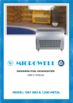
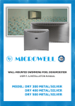
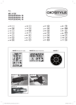
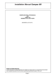
User´s and installation manual
SWIMMING POOL
DEHUMIDIFIER
Model:
DRY 500 DUCT
DRY 800 DUCT
DRY 1200 DUCT
Version: 2015-09-21
2|User´s and installation manual
Thank you for purchasing Microwell swimming pool dehumidifier. You
have exceptional piece of device and you chose the best and the most
energy efficient dehumidifier for your pool. Before you use this device, it is
necessary to carefully read the entire User’s manual. Please keep the
User’s manual available in the case of any future reference is required.
Please provide this information also to each user of the device. Please
mind local regulations in your country regarding installation and usage of
this dehumidifier which are valid in addition to this User’s manual.
CONTENT
1. WASTE DISPOSAL INFORMATION ................................................................................................................ 3
2. SAFETY MEASURES ...................................................................................................................................... 3
2.1 ELECTRICAL SAFETY ...................................................................................................................................... 3
2.2 USAGE PRECAUTIONS ................................................................................................................................... 4
2.3 HANDLING PRECAUTIONS ............................................................................................................................ 4
3. UNIT DESCRIPTION ...................................................................................................................................... 5
SWIMMING POOL DEHUMIDIFIER DRY 500/800/1200DUCT
4. INSTRUCTIONS FOR USE .............................................................................................................................. 6
4.1 HUMIDISTAT ..................................................................................................................................................... 6
4.2 CONTROL OF THE FAN ......................................................................................................................................... 8
4.3 COMPRESSOR CONTROL ...................................................................................................................................... 8
4.4 MAINTENANCE .................................................................................................................................................. 8
5. INSTALLATION GUIDE .................................................................................................................................. 9
5.1 LOCATION OF THE EQUIPMENT .............................................................................................................................. 9
5.2 MOUNTING OF THE UNIT ..................................................................................................................................... 9
5.3 COMPRESSOR TRANSPORT PROTECTION ................................................................................................................ 10
5.4 DRAINAGE OF CONDENSATE WATER ..................................................................................................................... 11
5.5 CONNECTION OF POWER SUPPLY ......................................................................................................................... 11
5.6 LPHW HEATING COIL FOR ADDITIONAL HEATING – ON DEMAND ................................................................................ 12
5.7 HOT GAS DEFROST (DRY500DUCT) – ON DEMAND............................................................................................... 13
6. TECHNICAL DATA ....................................................................................................................................... 14
6.1 TECHNICAL DATA TABLE *.............................................................................................................................. 14
6.2 EXTRACTION RATE DIAGRAMS ............................................................................................................................ 15
6.3 UNIT´S DIMENSIONS ........................................................................................................................................ 16
6.4 WIRING DIAGRAMS.......................................................................................................................................... 17
7. SUMMER SHUT-DOWN .............................................................................................................................. 25
8. WARRANTY ................................................................................................................................................ 25
User´s and installation manual |3
1. WASTE DISPOSAL INFORMATION
When using this dehumidifier in the European countries, the following information must be
followed:
DISPOSAL: Do not dispose this product as unsorted municipal waste. It is prohibited to
dispose this dehumidifier in domestic / household waste. It is prohibited to dispose this
appliance into forests or natural landscape. This could lead into local soil pollution.
Collection of such waste must be treated individually.
DISPOSAL POSSIBILITIES:
1. The municipality has established a collection system where electronic waste can be
disposed.
2. When buying a new product, the retailer or the manufacturer may take back the old
appliance free of charge.
3. As old appliance may contain valuable resources which could be sold to scrap material
dealers.
4. Disposal of packaging materials such as carton box or plastic / bubble foil can be recycled.
2. SAFETY MEASURES
Model Microwell DRY 500 DUCT is designed for halls with swimming pool surface of up to 50m2.
Model Microwell DRY 800 DUCT is designed for halls with swimming pool surface of up to 80m2.
Model Microwell DRY 1200 DUCT is designed for halls with swimming pool surface of up to 110m2.
For proper and optimal operations of the device is it necessary to maintain the air
temperature in the swimming pool room / hall 2-3°C higher than actual water temperature
in the pool. It is also necessary to keep the air temperature in the swimming pool room / hall
in operational temperature range of the dehumidifier (specified in Technical data section)
based on particular choice of Operational Temperature Accessories chosen for your
particular device. Lower air temperature than operational temperature range may cause
damage to the unit resulting from freezing. Higher temperatures than operational
temperature range may cause damage to the unit resulting from overheating of the unit.
It is necessary to follow instructions in this User’s manual and local regulations in your country that
regulate the installation and usage of this device. Incorrect, improper or operations contradictory to
this User’s manual may lead to an injury or property damage and will lead to loss of warranty. To
prevent injury or property damage the following instructions must be followed:
2.1 ELECTRICAL SAFETY
• The device operates at dangerous electrical current.
• Only authorized person with particular electro-technical qualification can manipulate with unit.
• Danger of electrical shock.
SWIMMING POOL DEHUMIDIFIER DRY 500/800/1200DUCT
This device is primarily designed for use in indoor swimming pool, sauna or spa. Alternative use is in
laundries, drying rooms or other humid areas requiring dehumidification.
4|User´s and installation manual
• Do not exceed the required power supply.
• Do not turn the device on that shows signs of possible damage such as broken packaging, broken or
otherwise damaged unit’s chassis or cover, smoke, smell, etc.
• It is necessary to use appropriate Residual current circuit breaker (RCD) for connection of the dehumidifier to
main power supply.
• Do not manipulate with the device with wet hands.
• Do not clean the device with water.
• Before cleaning the device, switch off the circuit breaker of the unit’s power supply.
• Installation, service or repair must be performed by qualified technician.
• When the device is not intended to be used for a longer time, we recommend switching the circuit breaker of
the unit’s power supply off.
• Unit must be installed in vertical position to avoid condensate water to enter electrical part of the unit.
• It is forbidden to install the unit close to devices that may cause electrical or frequency disturbance such as
welding machines, motors or rotors, WIFI/WLAN routers or repeaters.
• It is forbidden to alter electrical installation of the device. It is also forbidden to alter any other part or
functionality of the device.
SWIMMING POOL DEHUMIDIFIER DRY 500/800/1200DUCT
2.2 USAGE PRECAUTIONS
• Air outlet (exhaust) and air inlet (intake) are designed for connection to air ducting system.
• Do not cover or block the intake or exhaust openings. It is forbidden to block or cover the intake or exhaust
openings with clothes, towels, buckets, canoes, ceiling beams, etc.
• Do not install or place any heating appliances close to intake grilles / louvers. It could continually
overheat the dehumidifier and result in its malfunction or damage.
• Do not climb up on or sit on the unit.
• Do not place any objects on the top of the unit (e.g. boxes, flower vases, etc.).
• Do not spray any flammable substances into the equipment; this might lead to fire.
• Do not clean the equipment with aggressive cleaning agents, this might lead to damage or deformations.
• When cleaning plastic parts do not use any cleaning agents unsuitable for the cover of the dehumidifier
(household cleaning agents, solvents, bleaching agents, benzene, diluents, rough cleaning powder, cresol,
chemical agents). Instead, sweep the dehumidifier cover with a soft cloth or a sponge.
• Never throw or insert any objects into any hose or opening.
• The cover is made from powder coated metal. Do not manipulate with lighted cigarette, cigarette ashes, or
any other kind of fire in vicinity to this part.
• Use this device exclusively for the intended purpose, as described in the attached instruction manual. Do not
use parts which are not recommended.
• Do not drink or use the condensate water drained from the unit. Do not return the water back to the
swimming pool. The water may be contaminated with bacteria.
• Children are not allowed to operate, touch or play with the unit.
• Children are not allowed to manipulate with packaging, plastic / bubble foil. Risk of suffocation!
• Prevent the children from injury or harm caused by any manipulation with the unit, its parts or its
packaging. Small parts like screws may be swallowed and cause suffocation or harm to health.
• Do not leave the children in the swimming pool hall unattended.
2.3 HANDLING PRECAUTIONS
• Leave the unit in vertical upright position for at least 2 hours before the installation.
• Transport in lying position or turning the device over may harm the compressor and will lead to loss of
warranty.
• The device must be handled with care and special attention avoiding any mechanical damage.
• It is forbidden to apply any improper mechanical force onto the unit. This may cause mechanical damage to
the device.
• It is forbidden to let the device fall freely onto the ground or any solid surface resulting in hard impact.
User´s and installation manual |5
• Please notify your reseller or distributor if you suspect that the unit was delivered damaged. Unit may seem
to work well at start but small damage can make the unit go out-of-order in short time. In such case the unit
must be inspected and approved for further use by your reseller.
• Please notify your reseller or distributor if directly after installation you suspect that unit is not working in
perfect order.
• In the case of device failure resulting from improper handling or mechanical damage (impact, hit, fall, etc.),
the manufacturer reserves the right to evaluate the continuity of warranty.
3. UNIT DESCRIPTION
The unit was delivered in carton box on a wooden palette. Please unpack the unit and check the
content. It should include the following:
1. The dehumidifier
2. Wall console with fixation screws and dowels (DRY 500 DUCT), Floor feet (DRY 800/1200 DUCT)
or Wall console with fixation screws and dowels (DRY 800/1200 DUCT)
3. User’s manual
4. Condensate drain hose
5. Installation layout (DRY 500 DUCT)
Additional accessories to be included in the box (on demand):
1. Remote Wireless regulator DRY EASY 300
2. Remote Wired regulator EBERLE
3. Solenoid valve
1. Mobile stand
2. Through-the-wall adapter set
Exhaust grill / Air outlet
Ventilator /Main switch
Humidistat
Electrobox / power
supply connection
(under the cover)
/from below/
500mm
DRY500DUCT
Intake grill / Air inlet
Dimensions of air ducting connections
100mm
/from the back/
700mm
DRY800/1200DUCT
100mm
SWIMMING POOL DEHUMIDIFIER DRY 500/800/1200DUCT
Additional accessories to be included in separate box (on demand):
6|User´s and installation manual
Humid air is brought into the
dehumidifier.
It
leaves
the
dehumidifier dried and warmer by 520° than inlet air depending on air
temperature, humidity and LPHW
performance.
Humid air
Dry air
RECOMMENDATION: Cover your pool when not used. It will reduce the amount of
vapor in the air and energy costs needed to operate your dehumidifier.
4. INSTRUCTIONS FOR USE
4.1 Humidistat
SWIMMING POOL DEHUMIDIFIER DRY 500/800/1200DUCT
Your unit is equipped with built-in mechanical humidistat by standard and built-in digital humidistat
and thermostat by standard. On demand it can be equipped with remote wireless or wired regulator.
Regulation by remote regulators is described in their separate manuals coming with the regulators.
The built-in mechanical humidistat is located at the bottom of the unit on the
left (DRY 500 DUCT) or underneath the electrobox (DRY 800/1200 DUCT),
both under the dehumidifier’s cover. The humidistat reads the humidity of the
incoming air and depending on the preset value does or does not dehumidify.
This mechanical humidistat has a back-up function in case of digital humidistat
or remote controller malfuntion or failure. Mechanical humidistat is set to 70%.
User is advised not to change this settings.
The dehumidifier is being turned on and off by a digital humidistat with display. The built-in
humidistat is located in the cover of the device. It reads the humidiy of the incoming air and
depending on the preset value, initiates the dehumidification if needed. In indoor swimming pool
halls, the optimal air humidity level should range between 55% and 65 %. Decreasing the level of
humidity under the above mentioned range is not desirable, considerating the physiological aspects
as well as the aspects of providing building protection. Moreover, it increases the consumption of
electrical energy. The humidistat can be fully controlled by the user.
Luminous point signals, that
the temperature is shown
on display.
Luminous point signals,
that the humidity is shown
on display.
Luminous point indicates that
the regulator gives signal to
heat the air. This is
applicable if LPHW and
Solenoid valve are installed.
Not
illuminated
point
indicates that the requested
air temperature is lower than
actual.
Luminous point indicates that
the regulator gives signal to
dehumidify, i.e. requested
humidity is lower than actual.
Humidistat display (front view)
User´s and installation manual |7
FAILURE REPORTING:
0-E
S-E
Memory failure. Switch off and then switch on again the electrical connection. If the failure
reporting continues, please ask us to change the component.
Sensor failure. The electrical connection of the sensor is broken off.
Please control the cable.
Sensor failure. The sensor is short-circuited. Please control the cable.
SWIMMING POOL DEHUMIDIFIER DRY 500/800/1200DUCT
Er1
8|User´s and installation manual
Built-in digital humidistat is located on the front side of the unit’s cover. The unit is preset to keep
the humidity at 55%. User can set the humidity to requested value between 10-100%. Appropriate
relative humidity range in the swimming pool is between 55-65%. Lower humidity is not necessary; it
has no effect on building material or fabric protection and if dropped below 35% may
harm your mucous tissue. Higher relative humidity than 70% will result in building material or fabric
damage and also creates bacteria and mould favorable environment.
4.2 Control of the fan
A fan is very important part of a dehumidifier. Microwell has programmed the fan functionality in
order to ensure absolute humidity control in your pool with strong focus on energy efficiency. For
this reason all ducted dehumidifier models’s (DRY500DUCT, DRY800DUCT and DRY1200DUCT) fans
work on high speed when dehumidification is activated (compressor on) and are turned off when the
dehumidifier does not dehumidify (compressor off). In turn off stage, in order to ensure constant
control of the pool environment, the fans are programmed to perform a 2 min humidity reading
every 15 minutes. Should measured humidity be below requested level, the fans ‚go to sleep‘ for
another 15min. Should the humidity measured be above the requested level, the fans will be turned
on to high speed and the unit will initiate dehumidification.
Please check 6. TECHNICAL DATA (see Page 14) for fan air flow and external pressure. It is necessary
to design the air ducting in compliance with these technical parameters. Proper air circulation is
required to achieve proper humidity control in the swimming pool hall. It is advised to contact
professional air ducting company to design and install the ducting system.
SWIMMING POOL DEHUMIDIFIER DRY 500/800/1200DUCT
4.3 Compressor control
Start-up of the compressor is due to its protection delayed by 3 minutes. Depending on the humidity
of the environment, it may take even longer for compressor to start operating. Once the compressor
stops operating, the operation is renewed automatically at the earliest after three minutes. The user
must not alter the preset delay-action relay.
After longer time without operations when compressor attempts to turn itself on, it is
normal to take up to 4-6 turning-on attempts to finally turn the compressor on. This
depends also on current air temperature. Lower temperature environment (app. 22°C)
requires more attempts. Higher temperatures (30°C) less.
4.4 Maintenance
At least once a year it is necessary to have the unit checked and cleaned by a qualified service
specialist. This will ensure long and reliable service life of the unit.
User´s and installation manual |9
5. INSTALLATION GUIDE
The unit must be installed in compliance with the local installation and electrical
installation regulations!
5.1 Location of the equipment
5.2 Mounting of the unit
DRY 500 DUCT comes by standard with wall console and it is designed to be installed on the wall.
DRY 800/1200 DUCT comes by standard with floor feet designed to be installed on the floor.
Alternatively it is possible to install DRY 800/1200 DUCT on the wall using wall console.
Please note that the screws and dowels supplied with this dehumidifier are to be
used only with solid concrete or brick wall. Please check your wall material and
choose appropriate screw and dowel.
DRY 500 DUCT - Please use installation layout. It is 1:1 scale drawing of the
dehumidifier with markings for wall console screws, side fixation screws, water
drainage, electrical power supply and LPHW connection from the back.
SWIMMING POOL DEHUMIDIFIER DRY 500/800/1200DUCT
DRY 500 DUCT, DRY 800 DUCT and DRY 1200 DUCT are
designed to be installed in technical rooms. All models
are IP44 protected. For maintenance purposes it is
essential to have min 200mm of a free space on both
sides of the unit and min 750mm from the front side of
the unit. In technical chamber or adjacent room it is
necessary to have 2.25x1m2 of a floor surface.
10 | U s e r ´ s a n d i n s t a l l a t i o n m a n u a l
Brief installation instructions:
SWIMMING POOL DEHUMIDIFIER DRY 500/800/1200DUCT
DRY 500 DUCT
1. Confirm the position of the dehumidifier
and the wall console screws using
Installation layout.
2. Drill 3 holes, use appropriate dowels.
3. Fix the wall console tightly with
appropriate screws. Wall console must be
perfectly levelled using spirit level!
4. Remove the transport protection of the
compressor! More information below.
5. Hang the dehumidifier onto the wall
console.
6. Remove the right part of front cover (3
screws) and connect the electrical power
supply.
7. Put the condensate water hose into
drainage (from the back).
8. Turn the unit on and test it.
9. If unit works and appears to operate
normally, turn it off and continue with
installation finalization.
10.Set the ventilator mode (4.2 Control of the
fan). Put the right side of the cover back
and connect the air ducting from above
and below using 4 screws each (screws are
not supplied with the dehumidifier).
DRY 800/1200 DUCT
1. Confirm the position of a dehumidifier on
floor feet / wall console.
2. In the case of wall console fit both consoles
with 3 screws and dowels. Both consoles
must be levelled by spirit level. Screws are
supplied with the dehumidifier.
3. Remove the transport protection of the
compressor! More information below.
4. Level the dehumidifier using flexible feet /
fix the dehumidifier on the wall console
with screws (all coming in packaging).
5. Remove the left part of front cover (2
screws) and connect the electrical power
supply.
6. Put the condensate water hose into
drainage (from the back).
7. Turn the unit on and test it.
8. If unit works and appears to operate
normally, turn it off and continue with
installation finalization.
9. Put the right side of the cover back and
connect the ducting with 4 screws.
Wall console
Power supply
Water drainage
Picture: Preparation of wall installation for DRY500DUCT
5.3 Compressor transport protection
Your compressor is protected for the transport with plastic zipper strap. Due to compressor size and
weight this is necessary in order to have a fully functional unit delivered to you safely. This protection
must be removed before starting the unit. Please view below pictures on how to proceed. The
procedure generally takes few seconds. Please be advised that no removal of plastic zipper strap
results in warranty void.
U s e r ´ s a n d i n s t a l l a t i o n m a n u a l | 11
Picture 1: Plastic zipper strap
as delivered from factory.
Picture 2: To cut the strap
use pliers or other
appropriate tool.
Picture 3: Finally remove the
strap from the the
dehumidifier.
5.4 Drainage of condensate water
Correct drain hose
Installation.
Incorrect drain hose installation.
5.5 Connection of power supply
Connection of the unit onto the mains must conform to relevant safety standards. Connection
requirements: Power supply: 220-240V / 50Hz. Protection: 16A (DRY 500/800DUCT) or 20A
(DRY1200DUCT) by a protective switch (RCD) with nominal differential drop-out current not
exceeding 30 mA. The main switch of the unit must be situated outside of the swimming pool hall.
The main switch of the unit must be bipolar, with switch-out breaking of conductors L and N. An
appliance for disconnecting the unit from the mains must be embedded into a firm surface. The
distance of contacts, when switched off, must be at least 3 mm for all poles.
The connection of the appliance to the
electric mains must be carried out by a
certified electrician.
Please mind all electrical
precautions from page # 3
safety
Terminal board for connection
onto the electric mains.
SWIMMING POOL DEHUMIDIFIER DRY 500/800/1200DUCT
Condensed water is drained from the unit by the force of gravity (downwards). Unit’s condensate
tray is levelled to have sufficient declivity when the dehumidifier is perfectly levelled (using spirit
level). The condensation water must be drained through a siphon into a sewer or into the outside
environment. Please do not place the drainage hose upwards (against gravity), this will lead in unit’s
inability to drain the condensate water. This will subsequently cause water leakage from underneath
the unit’s cover and may lead to unit’s malfunction, damage or failure. Also it may cause the
underlying floor be wet, which creates danger of accident and harm to health resulting from
unwanted slip. Manufacturer, distributor or reseller are not responsible for such damages.
12 | U s e r ´ s a n d i n s t a l l a t i o n m a n u a l
5.6 LPHW heating coil for additional heating – on demand
The LPHW heater element is supplied on demand only. Connection of the LPHW onto the LPHW
plumbing is carried out similarly to the installation of radiators. On the feeder pipe, it is connected by
a control valve and on the return pipe by a closing screw joint. The LPHW is not supplied with a
control valve and a screw joint; these are supplied by the supplier of the heating.
Please note that DRY 500/800/1200 DUCT are in standard version equipped with
thermostat and no-current contact for heating.
The dehumidifier can be equipped with Solenoid valve on demand. In combined use
together with LPHW, the dehumidifier has the functionality of individual heating
appliance (fan coil), i.e. fan works independently with the compressor (humidistat) and
independently with LPHW (thermostat).
SWIMMING POOL DEHUMIDIFIER DRY 500/800/1200DUCT
If you chose LPHW with your dehumidifier without built-in digital humidistat &
thermostat and without remote wireless humidistat & thermostat, there is a risk of
dehumidifier overheating. Overheating may occur if hot water flows into LPHW also in
the time when the dehumidifier does not dehumidify (fan off). Normally, with built-in or
remote humidistat & thermostat and original solenoid valve, the dehumidifier controls
the hot water inflow automatically thus effectively avoids overheating damage. Without
original thermostat and/or solenoid valve it is necessary to ensure proper and effective
regulation of hot water inflow. Manufacturer, distributor or reseller do not bear
responsibility for damage resulting from not following above instructions.
LPHW connection options (from the back or from right) are described in section 7.3.
Unit’s dimensions.
DRY 500 LPHW nominal heating outputs
DRY 800/1200 LPHW nominal heating outputs
Heating output:
/W/
Heating output:
/W/
90/70/30 °C
4000
90/70/30 °C
6000
80/60/30 °C
3032
80/60/30 °C
4545
70/50/30 °C
2010
70/50/30 °C
3156
55/45/30 °C
1320
55/45/30 °C
1980
45/35/30 °C
528
45/35/30 °C
792
After installing the LPHW plumbing and leading the LPHW into the element under pressure, it is
necessary to bleed the heater element. The bleeding valve is located on the feeder pipe of the LPHW
heater element.
If Solenoid valve was supplied originally with the unit, please make sure it is properly connected to
water circuit. Otherwise the unit may suffer from overheating resulting malfunction or damage.
U s e r ´ s a n d i n s t a l l a t i o n m a n u a l | 13
It is highly advised to insert manual valves into water piping in between the LPHW and
water piping leading to a heat source /e.g. gas boiler/. This will allow easy and quick
dehumidifier disconnection from heating system.
5.7 Hot gas defrost (DRY500DUCT) – on demand
SWIMMING POOL DEHUMIDIFIER DRY 500/800/1200DUCT
Hot gas defrost allows the dehumidifier to operate effectively at air temperatures down to 5°C. It is
designed for heavy duty low air temperature operations. Although the efficiency of the device
concerning the extraction rate versus energy consumption by 5°C ambient air temperature
conditions is low, the dehumidifier will still operate normally. If your dehumidifier is equipped with
hot gas defrost accessory, then the gas circuit is equipped with 4-way valve. When temperature on
evaporator drops below zero, system starts to count 30 minutes of a time. After this period, the
evaporator temperature is checked again and if the current temperature is still below zero, the
compressor and the ventilator are turned off. Dehumidification stops. Gas circuit is reversed and
after 3 min the compressor starts. System now defreezes the unit for 3 minutes. After another 3
minutes, if the defrost cycle is completed, the unit goes into usual operations. In extremely low
temperatures and in still humid enough air it is normal to take 2 or 3 defreezing cycles to complete
the procedure.
14 | U s e r ´ s a n d i n s t a l l a t i o n m a n u a l
6. TECHNICAL DATA
6.1 Technical data table *
SWIMMING POOL DEHUMIDIFIER DRY 500/800/1200DUCT
DATA
For swimming pools with max. water
surface
Exctraction rate at 30°C and 60 % RH
Exctraction rate at 30°C and 70 % RH
Exctraction rate at 30°C and 80 % RH
Operational temperature - standard
Operational temperature - antifreeze
stat
Operational temperature Thermostatic expansive valve (TEV)
Operational temperature - antifreeze
stat + TEV
Operational temperature - hot gas
defrost
Operational humidity range
Air flow
EXTERNAL PRESSURE
Noise level (in 1m distance)
Heat output
Energy consumption
Voltage
Operating / Starting current
Protection
Conductor
Condensed water pipe
UNIT
m2
l/24hrs
l/24hrs
l/24hrs
°C
°C
°C
°C
DRY 500 DUCT
DRY 800 DUCT
DRY 1200 DUCT
50
80
110
52
60
68
22-35
88
115
135
22-35
112
140
170
22-35
15-35
15-35
15-35
22-42
-
-
15-42
-
-
°C
% RH
m3/h
Pa
dB (A)
W
W
V/Hz/f
A
A
mm2
mm
5-35
-
-
20-100
800-1200
300-200
56/58
3500
1150-1500
230/50/1
6.5 / 30
16
CYSY 3C x 2,5
d 18
20-100
1200
200
58
5100
1700
230/50/1
7.6/50
16
CYSY 3C x 2,5
d 18
20-100
1400
190
60
5250
2250
230/50/1
10/50
20
CYSY 3C x 2,5
d 18
Dimensions netto (width x height x
depth)
mm
1245 x 660 x 253
1247 x 950 x 300
1247 x 950 x 300
Dimensions brutto (width x height x
depth)
mm
1315 x 735 x 345
1300 x 1020 x 370
1300 x 1020 x 370
Weight netto / brutto
kg
75 / 88 kg
102/135 kg
103/136 kg
Amount of refrigerant - R 410 A
Max. pressures in the system HP/LP
kg
bar
0,75
28,5/8,5
1,6
35/12
1,9
35/12
* Manufacturer reserves the right to change above data without notice.
Gas circuit is filled with refrigerant R410A which is two-content refrigerant (R32/R125). Based on ES No. 842/2006 are these
contents considered to be a fluorcarbon greenhouse gases. The unit contains fluorcarbo greenhouse gases included in Kyoto
Protocol:
R410A with global warming potential (GWP) 1720:
(R-32/125 50/50)
CH F +CF CHF
750 g (DRY 500 DUCT)
1600g (DRY800 DUCT)
1900g (DRY1200 DUCT)
This information is informatory, for exact amount of refrigerant in your device, please turn to serial number sticker (located in
the upper right corner of the unit from the back).
U s e r ´ s a n d i n s t a l l a t i o n m a n u a l | 15
6.2 Extraction rate diagrams
DRY 500 DUCT
(l/24h)
80
R ela tive hu midity
Extraction rate
70
60
50
40
30
20
15
20
25
30
35
Air temperature (°C)
DRY 1200 DUCT
SWIMMING POOL DEHUMIDIFIER DRY 500/800/1200DUCT
DRY 800 DUCT
16 | U s e r ´ s a n d i n s t a l l a t i o n m a n u a l
6.3 Unit´s dimensions
DRY 500 DUCT
View from above
1
1
From left
1
2
From right
Front view
3
9
6 10 View from below
6
6
9
8
SWIMMING POOL DEHUMIDIFIER DRY 500/800/1200DUCT
4
5
LEGEND:
1 - DRY AIR OUTLET
2 - DIGITAL HUMIDITY REGULATOR
3 - LPHW CONNECTOR – ON DEMAND
4 - VENTILATOR SWITCH
5 - MAIN SWITCH
6 - HUMID AIR INLET
7 - AUXILIARY MECHANICAL
HUMIDISTAT
8 - CONDENSATE DRAIN FROM THE
BOTTOM
9 - ELECTRICITY CONNECTION
10 - CONDENSATE DRAIN FROM BEHIND
7
DRY 800/1200 DUCT
1
2
5
1
3
9
6
6
8
1
U s e r ´ s a n d i n s t a l l a t i o n m a n u a l | 17
SWIMMING POOL DEHUMIDIFIER DRY 500/800/1200DUCT
6.4 Wiring diagrams
SWIMMING POOL DEHUMIDIFIER DRY 500/800/1200DUCT
18 | U s e r ´ s a n d i n s t a l l a t i o n m a n u a l
SWIMMING POOL DEHUMIDIFIER DRY 500/800/1200DUCT
U s e r ´ s a n d i n s t a l l a t i o n m a n u a l | 19
SWIMMING POOL DEHUMIDIFIER DRY 500/800/1200DUCT
20 | U s e r ´ s a n d i n s t a l l a t i o n m a n u a l
SWIMMING POOL DEHUMIDIFIER DRY 500/800/1200DUCT
U s e r ´ s a n d i n s t a l l a t i o n m a n u a l | 21
SWIMMING POOL DEHUMIDIFIER DRY 500/800/1200DUCT
22 | U s e r ´ s a n d i n s t a l l a t i o n m a n u a l
SWIMMING POOL DEHUMIDIFIER DRY 500/800/1200DUCT
U s e r ´ s a n d i n s t a l l a t i o n m a n u a l | 23
SWIMMING POOL DEHUMIDIFIER DRY 500/800/1200DUCT
24 | U s e r ´ s a n d i n s t a l l a t i o n m a n u a l
U s e r ´ s a n d i n s t a l l a t i o n m a n u a l | 25
7. SUMMER SHUT-DOWN
Some swimming pool users use to shut the dehumidifier for summer down. This is mainly due to
favourable weather conditions with dry and warm weather. In such case, good air ventilation /
natural air exchange does the job of humidity control for few weeks/months of the year.
Although following rapid change in weather (e.g. into rainy days) may result in high humidity in
your pool.
In this case please make sure that:
1.
Dehumidifier's circuit breaker is off (i.e. dehumidifier does not have any power supply)
2.
Dehumidifier is cleaned of duct, fluff or other dirt that may harden / stiffen its structure
during the shut down period making it hard to remove afterwards.
3.
Make sure air inlet and outlet are covered properly so no chlorine or other chemicals are not
input into dehumidifier body, especially ventilator bearings. Failing to do so may result in
bearings corrosion and failure of the dehumidifier.
4.
Manufacturer does not suggest any planned shut down of the system because during shut
down period the humidity is not controlled effectively and automatically.
This dehumidifier is subject to a warranty period of 2 years. It may have been prolonged in your
country or by your distributor or reseller. Please contact your reseller or distributor in the case a
warranty should be claimed for this dehumidifier.
Please note that no claims will be accepted (warranty void) if:
1. The dehumidifier has been used in an incorrect way, not as described in this manual or in
contrary to this User’s manual or against Safety measures of this User’s manual.
2. The dehumidifier is installed in an incorrect way, not as described in this User’s manual or in
contrary to this User’s manual.
3. The dehumidifier was put to operation by an unauthorized person.
4. The air flow through the dehumidifier is out of the defined borders.
5. The unit has been exposed to a mechanical damage / force or any unauthorized action was
performed on construction of a unit - welding, brazing or has been mechanically damaged
resulting in scratches, blends, compressions, pipe rupture, etc. No mechanical damage is
accepted as warranty claim unless a written claim had been made with transporting agent
delivering the device.
6. Chemical conditions in the pool or pool hall have not been within the defined borders (please
see below table Allowed chemical conditions).
7. The dehumidifier suffered frost or overheating damage resulting from ambient air
temperatures out of Temperature operational range.
8. The electric tension source is insufficient or improper in any other way.
When applying for warranty, please contact your distributor and indicate dehumidifier
model, serial number and date of purchase. Please describe the genesis of the failure.
SWIMMING POOL DEHUMIDIFIER DRY 500/800/1200DUCT
8. WARRANTY
26 | U s e r ´ s a n d i n s t a l l a t i o n m a n u a l
Acidity / pH level:
Total alkalinity, as CaCO3
Total hardness, as CaCo3
Total melted dry mass
Maximal saline content
Free chlorine range
Superchlorination
Bromine
Baquacil
Ozone
Maximum copper content
Aquamatic single purifier
Tarn clean purifier
Sherwood purifier
pH
ppm
ppm
ppm
wt/wt
ppm
ppm
ppm
ppm
ppm
ppm
ppm
ppm
ppm
7,4 +/- 0,4
80-120
100-300
max. 3000
6%
1,0-3,0
max. 30 ppm/max. 24 hours
2-3
25-50
0,8-1,0
max. 2
max. 2
max. 2
max. 2
Table: Allowed chemical conditions
SWIMMING POOL DEHUMIDIFIER DRY 500/800/1200DUCT
TRANSPORT INSTRUCTIONS
The dehumidifier must be transported in the original packaging only and in
a vertical upright position. Make sure that the dehumidifier cannot turn over or fall
down during transport. Never put the dehumidifier aside! It may lead to serious
compressor damage!
No mechanical damage is accepted as warranty claim unless a written claim had
been made with transporting agent delivering the device. When receiving the
product please check whether the package is not damaged. Please make a proper
documentation of any damage immediately after delivery and claim all transport
damage in written form with the forwarding agent at the delivery.
Manufacturer:
MICROWELL, spol. s r.o.
SNP 2018/42, 927 01 Šaľa, Slovakia
tel.: +421/31/702 0540
fax: +421/31/702 0542
e-mail: [email protected]
www.microwell.eu
Made in EU
Distributed by: