1
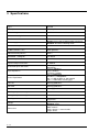
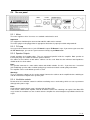
PROLUDE AMPLIFICATION
BHV450 and BHV450L
Bass amplifier
User’s manual
1—2
Table of contents
1
1.1
1.2
2
2.1
2.2
2.3
2.4
INTRODUCTION................................................................................................................................1—4
SOME WORDS TO THE CUSTOMER ....................................................................................................1—4
SOME WORDS ABOUT ME ...................................................................................................................1—4
SAFETY INSTRUCTIONS, WARNINGS ........................................................................................2—5
BASIC PRECAUTIONS .........................................................................................................................2—5
WARNINGS USED ON THE EQUIPMENT..............................................................................................2—5
GROUNDING INSTRUCTIONS..............................................................................................................2—5
CE MARK FOR EUROPEAN HARMONISED STANDARDS ....................................................................2—5
3
SPECIFICATIONS..............................................................................................................................3—6
4
INFORMATION FOR INSTALLING ..............................................................................................4—7
5
CONTROLS AND FUNCTIONS .......................................................................................................5—8
5.1
5.2
5.3
5.4
6
THE FRONT PANEL .............................................................................................................................5—8
THE REAR PANEL .............................................................................................................................5—11
BLOCK DIAGRAM .............................................................................................................................5—12
OTHER FUNCTIONS, PROTECTIONS.................................................................................................5—12
MAINTENANCE, CLEANING .......................................................................................................6—14
1—3
1 Introduction
1.1
Some words to the Customer
Welcome to the club of Prolude Amplification owners! It is my pleasure to have you as a member in this
small team of people who have taken notice of my handwork and intellectual product, and finally have voted
for it. I hope you will feel the same as they do while your amplifier, this small part of your musical production
chain, is reliably working behind you.
1.2
Some words about me
My name is Róbert Fülöp. My favourite musical instrument is the bass guitar. Its sound, shape and role
within the music have all contributed to my enthusiasm. To start with, my studies and my sphere of interest
have both moved me to the direction of electronics. As a result PROLUDE AMPLIFICATION was born at the
beginning of the new millennium. My goal is to provide bass players with the best possible sound quality.
Being an electrical engineer I’m doing it mainly with a technical mindset. However - according to the
feedbacks from my satisfied customers – the musicality is also present in the final product.
The technical development has been a long process so far - end it will never come to an end. I will make
further efforts to improve the product, thus satisfying the steadily changing expectations of the customer.
1—4
2 Safety instructions, warnings
2.1
Basic precautions
WARNING - When using electrical products, basic precautions should be followed, including the following:
Read all the instructions before using the product.
Do not use this product near water – for example, near a bathtub, washbowl, kitchen sink, in a wet basement
or near a swimming pool.
This product may cause permanent hearing loss. Do not operate for long periods of time at a high volume
level or at any level that is uncomfortable.
Make sure nothing interferes with the ventilation of the product when in use.
The product should be located away from heat sources such as radiators, heat registers, or other products
that produce heat.
The product should be connected to a power supply of the type described in the operating instructions or as
marked on the product.
The power supply cord of the product should be unplugged from the outlet when left unused for a long period
of time.
Care should be taken so that objects do not fall and liquids are not spilled into the enclosure through
openings.
The product should be serviced by qualified personnel when:
- The power supply cord or the plug has been damaged; or
- Objects have fallen, or liquid has been spilled into the product; or
- The product has been exposed to rain or moisture; or
- The product does not appear to operate normally or exhibits marked change in performance; or
- The product has been dropped, or the enclosure damaged.
10. Do not attempt to service the product. All servicing should be referred to qualified service personnel.
11. For continued protection against the risk of fire, replace fuses only with those of the same type and
rating.
2.2
Warnings used on the equipment
The lightning flash with the arrow head symbol within an equilateral
triangle is intended to alert the user to the presence of uninsulated
‘dangerous voltage’ within this product’s enclosure that may be of
sufficient magnitude to constitute a risk of electric shock.
The exclamation point within an equilateral triangle is intended to
alert the user to the presence of important operating and
maintenance (servicing) instructions in the literature accompanying
this product.
2.3
Grounding instructions
This product must be grounded (earthed). If it should malfunction or break down, grounding provides a path
of least resistance for electric current to reduce the risk of electric shock. This product is equipped with a
supply cord having an equipment grounding conductor and a grounding plug. The plug must be plugged into
an appropriate outlet that is properly installed and grounded in accordance with the local codes and
ordinances.
DANGER - Improper connection of the equipment grounding conductor can result in a risk of electric shock.
Check with a qualified electrician or serviceman if you are in doubt as to whether the product is properly
grounded. Do not modify the plug provided with the product – if it will not fit the outlet, have a suitable outlet
fitted.
2.4
CE mark for European harmonised standards
The CE mark which is attached to these products means it complies with the EMC Directive (89/69/EEC),
CE mark directive (93/68/EEC) and Low Voltage Directive (72/23/EEC).
2—5
3 Specifications
Type
BHV450
Description
Bass amplifier
Mains voltage
230VAC 50Hz
Mains connecting device
Standard mains cord
Inrush current limiter
NTC
Power supply
BHV450: Conventional 700VA toroid transformer
BHV450L: Resonant switching mode
Power consumption
700W
Output power
/100Hz continous sine/
450W @4Ohms
280W @8Ohms
Minimal load impedance
4Ohms
Bandwidth -+3dB@1W
7Hz-40kHz
Power amplifier
Class AB, transistor
Speaker output connectors
Instrument input connectors
Input impedance
Active Equalization
Neutrik Speakon-Jack combo
NLJ2MD-H
Neutrik 6,3mm Jack
NMJ4HFD2
Passive: 500kohms
Active: 25kohms
FX Return: 15kohm
Low +/-12dB@40Hz
Low-Mid: +/-12dB@500Hz
Mid: +/-12dB @ Mid-freq: 800-3200Hz
High: +/-12dB 10kHz shelving type
Line out
250mVp@600Ohms
FX Send
350mVp@220Ohms
Phone
750mVp@110Ohms
Working temperature range
0-40°C
Storage temperature range
-25-60°C
Cooling
Weight
Dimensions
3—6
Fixed speed ventilator based
temperature
BHV450: 9kg
BHV450L: 5,2kg
2U high 19” rack
Width: 482mm
Depth: 255mm, + 35mm handle
Height: 88mm
on
heatsink
4 Information for installing
At high power level it is neccesarry to consider the wiring between the amplifier and speaker cabinets.
In most cases the amplifier is placed on top of the speaker cabinet, therefore a very short speaker cable can
be used for connecting the two. This is very good, because the shorter and thicker the loudspeaker cable,
the better.
Do not use an instrument cable for connecting speaker cabinets!
Use high quality / Neutrik / SPEAKON-SPEAKON speaker cable with at least 2x1,5mm2 or more cross
section. They are reliable, robust and have less influence on the sound.
Use a speaker cable in good condition and connect the speaker cabinet to the amplifier before you switch on
the amplifier.
Try to minimize the number of power strips used to connect the amplifier to the mains.
Use high quality, shielded instrument cable for connecting your instrument to the amplifier.
At high volume level the speaker cabinet might vibrate, so make sure that the placing is stable and the
amplifier can not move anywhere.
4—7
5 Controls and functions
5.1
The front panel
5.1.1 Active
Input jack for active instruments.
5.1.2 Passive
Input jack for passive instruments
Note:
There is no significant difference between the two inputs other than the input impedance and sensitivity. The
passive instruments and the preamplifierless piezo pickups „prefer” the Passive input, because of its higher
impedance and sensitivity.
5.1.3 Gain
This controls the overal signal level of the preamplifier section. Various instruments produce different signal
levels. The Gain control helps you to set these to the ideal signal level for the preamplifier section.
The two colour / green – red / LED – placed right from the Gain knob - is your feed back to set best signal
level.
The Gain setting is OK, if the LED is blinking beetween green and red. It is OK to go red when you make a
powerfull plucking.
Note:
The setting described above is not a rule. Adding more Gain will not cause any problem. In such a case you
get a larger singnal level with some drive, especially when the Valve Loop is activated. In some situations
this can sound good. At this point you have to consider the power handling of your speakers, because the
overdriven sound strains them more.
If you set the Gain too low the preamp section will not send enough signal to the power stage and the output
power may be not enough and may also detain the proper functioning of the Noise Gate.
5.1.4 Bright
Boosts the highs adding brightness to your sound.
5.1.5 Shape
Mildly boosts the lows and highs whilst cutting the mids. You can switch on this function also with the first
button of the Footswitch. In this case, however, the button on the front panel has to be in inactive position.
5.1.6 Valve Loop
A switchable section in the preamplifier with a double triode valve. It gives more warmth to your sound and
contains a passive tone control circuit with Bass and Treble knobs.
This function can be activated with the On button.
5—8
5.1.7 Noise Gate
Automaticly softens down the amplifier during the pauses of your performance. Eliminates hum, buzz or
single coil noise, which are audible when you stop playing. You can adjust the treshold with the
potentiometer. The sounds below this treshold are recognized as noise and soften down.
Setting the treshold:
1. Set up your sound and volume on the amplifier
2. Switch on the Noise Gate with minimal treshold / this is the most sensitive setting
3. After some soft playing damp the strings
4. If you recognize the elimination of noise, you are finished
5. If you do not recognize it, turn up the treshold a little and go back to point three
Wrong setting:
If the threshold is set too low the Noise Gate will not be activated to soften the noise when you stop playing.
If the threshold is set too high the softening comes too early, thus cutting the sustained sound.
Note:
The Noise Gate will only work properly at good Gain setting.
Normally if there is no noise generating effect or stomp box / like overdrive or distortion / in the signal path
there is no need to turn up the treshold level, just switch on the Noise Gate!
5.1.8 Active Equalization
Four band active equalization system with Low, Low-Mid, semi-parametric Mid and High controls. If you
leave the knobs centered, you get a linear, uncoloured sound.
You can bypass this feature with the second button of the footswitch.
5.1.9 Comp
Dynamic compressor. At the lowest position of the potentiometer this feature is inactive. By turning up it
produces more gain and simultanously brings down the threshold level, where the limitation starts.
Generally, the softer playing gets more gain, than the louder. The limitation area is feed back by the blue
LED placed left to the Comp knob.
5.1.10 Volume
Controls the overall volume of the Speaker Outputs. The Line-Out, the Phone and FX-Send are not
affected by this potentiometer.
5.1.11 Mute
Mutes the Speaker Outputs, the Phone and the Line-Out, but the FX Send is not affected. If the button is
pressed, the red LED is bright.
Note:
This Mute LED gives you additional information too, see section 5.1.16.
5.1.12 Phone
Phone output drives stereo headphones / in mono mode /. Its volume can be controlled by the Gain
potentiometer.
5.1.13 Foot Sw.
Footswitch input. You can connect a two-buttons footswitch here via a stereo jack cable.
You can activate the Shape function with the first button and bypass the Active Equalization by the second
one.
5—9
5.1.14 Line Out
Balanced Line Out with Neutrik XLR connector. It gives a high quality line level signal to be used for PA or a
recording system. The GND Lift button disconnects pin 1 of the XLR connector.
Note:
In most cases the GND Lift button has to be unpressed! When you get ground loop, hum or buzz while
connecting to PA or a recording system pressing the button may help to eliminate this.
The Phone output provides an unbalanced, higher signal level. You can use it also for connecting to a
computer’s soundcard.
5.1.15 Mains
You switch on the amplifier with this switch. After switching on there is a ventilator test for about 5 seconds,
after which the amplifier is in ready mode.
Important:
Please avoid switching on and off the amplifier too often, especially after playing at high volume level! After
playing at high volume level give the ventilator a few minutes to cool down the amplifier before switching it
off!
5.1.16 Mute LED
Multifunctional feedback LED.
Bright when:
- the Mute button is pressed;
Or if unpressed:
- after switching on, during the ventilator test
- when the power stage is overheated
- when the power stage is in a fault state
5—10
5.2
The rear panel
5.2.1 Mains
The mains appliance inlet. You must use standard earthed mains cord.
Important!
This equipment should only be connected to 230VAC, 50Hz mains network!
The mains plug must be plugged into an appropriate outlet that is properly installed and grounded!
5.2.2 FX Loop
Insert your effects between these jacks. FX Send is output, FX Return is input. If you connect your tuner into
this FX Send output, you can tune your instrument silently usig the Mute button.
5.2.3 Speaker Outputs
Neutrik Speakon-Jack combo outlets. They are conntected parallel inside the amplifier. Both speakon or
6,3mm jack plugs are suitable to connect speaker cabinets.
One 4ohms or one 8ohms or two 8ohms cabinets can be used. Note that the minimum load impedance
should not be less than 4ohms.
Note:
The speakon connector is a more stable, robust and reliable solution. Use this - if you have one - instead of
jack! Avoid long speaker cables and low quality plugs in order to maintain sound quality and volume.
The amplifier can be used without speakers as well.
Warning!
There is dangerous voltage on the speaker output! Connect the cabinets to the amplifier before switching on
and do not touch the hot pole of the speaker jack!
5.2.4 Ventilation cutouts
Do not cover the ventilation cutouts! Insufficient ventilating causes overheating, which can cause permanent
damage to the power stage.
Note:
Overheating or fault of power stage is displayed by the Mute LED.
If this occurs, switch off the amplifier, wait for 30 minutes before then switching it on again! If the Mute LED
stays lit after the ventilator test /4-5 seconds/ then the amplifier has to be brought to a qualified technician for
repair.
5—11
5.3
Block diagram
Active
Passive
Bright
Gain
1.
Input
stage
2.
Preamp
Shape
/ FS1
3.
Shape
Bass, Treble, On
4.
Valve
Loop
Low, Low-Mid, Midfreq, Mid, High
FS2
5.
Active Eq.
Send
16.
Limiter
Return
10.
Level
Det.
Mute
Volume
6.
Comp.
7.
Volume
Control
11.
Noise
Gate
12.
Phone
Amp.
Phone Out
14.
Overheat
Sense
13.
Line
Buffer
Line Out
15.
Fan
Control
Noise Gate,
On
8.
Power
Amp.
9.
Speaker
Prot.
Speaker
Out
GND Lift
5.4
Other functions, protections
5.4.1 Short circuit protection
The amplifier contains a protection circuit against wrong / shorted / speaker cable or burnt speakers.
5.4.2 Speaker protection
The speaker cabinets are protected against a possible malfunction of power stage. This circuit detaches the
speaker cabinets when power stage fault occurs, protecting the cabinets from halmful direct current.
5.4.3 Click noise reduction
The connection of the speaker cabinets is internally delayed after switching on, therefore there is no click
noise on the speaker cabinets when switching on or off.
5—12
5.4.4 Overheat protection
Due to insufficient ventilation, ventilator fault or too high environment temperature while playing at high
volume, overheating may occur. In such a case the protection circuit detaches the speaker cabinets until the
temperature of the power stage cools down. This is being displayed by the Mute LED.
5.4.5 Ventilator control
The control of the cooling ventilator is based on the temperature of the power stage’s heatsink. It
automatically switches itself on when the temperature reaches 60°C and switches itself off when temperature
decrease below 50°C.
Do not cover the ventilation cutouts!
5.4.6 Limiter
This function protects the power section against distortion. When it detects distortion on the output,
decreases the input signal of the power stage. In practise, there is no significant distortion on the power
stage when you overdrive it, the system will only lose some of its dynamics.
5—13
6 Maintenance, cleaning
The amplifier has no need for particular maintenance.
Occasionally check the starting of the ventilator when you switch on the amplifier!
The preamplifier valve is a long life type, probably you will never have to replace it because of aging.
However, if you feel you are losing sound quality you can easily check it by switching on and off the Valve
Loop. Replacing valves must be done by a qualified person. Only replace by using valves of the same type.
Use only soft and dry or dampened cloth for cleaning. Avoid agressive, caustic cleaning materials.
6—14
6—15